

Sony SLT-A65, SLT-A65L, SLT-A65K, SLT-A65M, SLT-A65V Service Manual
...
SLT-A65/A65K/A65L/A65M/A65V/A65VK/A65VL/A65VM/A65VX/A65VY/A65X/A65Y_L2
Sony Corporation
SERVICE MANUAL
Revision History
SERVICE NOTE (Check the following note before the service.)
LEVEL 2
983460937.pdf
2013G08-1
© 2013.07
Published by Sony Techno Create Corporation
Ver. 1.6 2013.07
INTERCHANGEABLE LENS DIGITAL CAMERA
US Model
Canadian Model
AEP Model
UK Model
E Model
Australian Model
Chinese Model
Korea Model
Japanese Model
Tourist Model
1-1. METHOD FOR REPLACING THE P.O.I.
1-2. ADDITION OF DESTINATION DATA FILE
1-3. PRECAUTION ON REPLACING THE AM-026 BOARD
1-4. METHOD FOR CHECKING THE AS SLIDER UNIT (870)
1-5. METHOD FOR ADJUSTING THE TEBURE REVISE
1-6. METHOD FOR REPLACING THE AS SLIDER B ASSY
1-7. METHOD FOR REPLACING THE AS HOLDER ACTUATOR ASSY
1-8. GPS RECEIVING CHECK (SLT-A65V/A65VK/A65VL/A65VM/A65VX/A65VY)
1-9. NOTE ON REMOVING THE AP IRIS RING
1-10. HOW TO CHARGE THE APERTURE
1-11. METHOD OF CONFIRMING THE PHASES OF AP IRIS RING AND AP SENSOR GEAR
9-834-609-37
Photo: SLT-A65V
[About the service of this model]
SLT-A65K/A65L/A65M/A65VK/A65VL/A65VM/A65VX/A65VY/A65X/A65Y are commodity that packed the Interchangeable Lens Digital Camera
and Interchangeable Lenses.
Refer to each following service manual the Interchangeable Lens kit, when you repair.
Model Lens Service Manual of Lens
SLT-A65/A65V No supplied lens No supplied lens
SLT-A65K/A65VK SAL1855 (DT 18-55mm F3.5-5.6 SAM) 9-852-691-[]
SLT-A65L/A65VL SAL18552 (DT 18-55mm F3.5-5.6 SAM II) 9-834-733-[]
SLT-A65M/A65VM SAL18135 (DT 18-135mm F3.5-5.6 SAM) 9-834-677-[]
SLT-A65VX/A65X SAL18552 (DT 18-55mm F3.5-5.6 SAM II) 9-834-733-[]
SAL55200-2 (DT
55-200mm F4-5.6 SAM) 9-852-692-[]
SLT-A65VY/A65Y SAL1855 (DT 18-55mm F3.5-5.6 SAM) 9-852-691-[]
SAL55200-2 (DT
55-200mm F4-5.6 SAM) 9-852-692-[]
– ENGLISH –
– JAPANESE –
1-1. P.O.I.の交換方法
1-2. DestinationDataファイルの追加について
1-3. AM-026基板交換時の注意
1-4. ASスライダーユニット(870)チェック方法
1-5. 手ぶれリバイス調整方法
1-6. ASスライダー BASSYの交換方法
1-7. ASアクチュエータホルダASSYの交換方法
1-8. GPS受信確認(SLT-A65V/A65VK/A65VL/A65VM/A65VX/A65VY)
1-9. AP絞りリング取り外し時の注意
1-10. 絞りチャージ方法
1-11. AP絞りリングとAPセンサーギアの位相確認方法
Ver. Date History Contents
S.M. Rev.
issued
1.0 2011.09 Official Release — —
1.1 2011.10 Revised-1
(A1 11-223)
• Correction of EXPLODED VIEWS.
Page 2-14
Yes
1.2
2012.04 Revised-2
(A2 12-053)
• Correction of SERVICE NOTE.
Page 1-1, 1-2, 1-3, 1-4, 1-5, 1-6, 1-7, 1-8, 1-9, 1-10, 1-11, 1-12
• Correction of REPAIR PARTS LIST.
Page 2-6, 2-7, 2-8, 2-12, 2-13, 2-15
• Correction of ACCESSORIES.
Page 2-17
Yes
1.3
2012.05 Revised-3
(A3 12-088)
• Change of REPAIR PARTS LIST.
Page 2-11
Yes
1.4 2012.06 Revised-4
(A4 12-099)
• Addition of AEP model in SLT-A65/A65K, and addition of SLT-A65M/
A65VM/A65Y.
Page 2, 3, 1-5, 1-11, 2-6, 2-7
Yes
1.5
2012.11 Revised-5
(A5 12-266)
• Correction of ASSEMBLY.
Page 3-1
Yes
1.6 2013.07 Revised-6
(A6 13-032)
• Addition of SLT-A65L/A65VL/A65VX/A65X.
Page 3, 1-5, 1-11, 2-1, 2-4, 2-6, 2-7, 2-9
Yes
The components identified
by mark 0 or dotted line with
mark 0 are critical for safety.
Replace only with part number
specified.
Les composants identifiés par
une marque 0 sont critiques
pour la sécurité.
Ne les remplacer que par une
pièce portant le numéro spécifié.
SLT-A65/A65K/A65L/A65M/A65V/A65VK/
A65VL/A65VM/A65VX/A65VY/A65X/A65Y
Revised-6
Replace the previously issued
SERVICE MANUAL 9-834-609-36
with this Manual.
SLT-A65/A65K/A65L/A65M/A65V/A65VK/A65VL/A65VM/A65VX/A65VY/A65X/A65Y_L2
– 2 –
SPECIFICATIONS
– ENGLISH – – JAPANESE –
概略仕様
Camera
[System]
Camera Type
Interchangeable Lens
Digital Camera
Lens A-mount lens
[Image sensor]
Image format
23.5 mm×15.6 mm
(APS-C format) CMOS
image sensor
Total pixel number of image sensor
Approx. 24 700 000 pixels
Effective pixel number of camera
Approx. 24 300 000 pixels
[SteadyShot]
For still images
System: Image sensor-shift
mechanism
Effect: Approx. 2.5 EV to 4.5 EV
in shutter speed (depending on
shooting conditions and the
attached lens)
For movies System: Electronic
[Anti-Dust]
System Charge protection coating on
Low-Pass Filter and image
sensor-shift mechanism
[Auto focus system]
System TTL phase-detection system,
15 points (3 points cross type)
Sensitivity Range
–1 EV to 18 EV (at ISO 100
equivalent)
AF illuminator
Approx. 1 m to 5 m (3.3 feet to
16.4 feet)
[Electronic viewfinder]
Type Electronic viewfinder
(Organic Electro-
Luminescence)
Screen size 1.3 cm (0.5 type)
Total number of dots
2 359 296 dots
Frame coverage
100%
Magnification
1.09 × with 50 mm lens at
infinity, –1 m
–1
(diopter)
Eye Point Approximately 27 mm from
the eyepiece, 22 mm from the
eyepiece frame at –1 m
–1
Dioptor Adjustment
–4.0 m
–1
to +3.0 m–1 (diopter)
[LCD monitor]
LCD panel 7.5 cm (3.0 type) TFT drive
Total number of dots
921 600 (640 × 3 (RGB) ×
480) dots
[Exposure control]
Metering Cell
“Exmor” CMOS sensor
Metering method
1 200-zone evaluative
metering
Metering Range
–2 EV to +17 EV on Multi
segment, Center weighted,
Spot modes (at ISO 100
equivalent with F1.4 lens)
ISO sensitivity
(Recommended exposure index)
AUTO, ISO 100 to 16 000
(1 EV step)
Exposure compensation
±3.0 EV (1/3 EV step)
[Shutter]
Type Electronically-controlled,
vertical-traverse, focal-plane
type
Speed range
1/4 000 second to 30 seconds,
bulb
Flash sync speed
1/160 second
[Built-In-Flash]
Flash G.No.
GN 10 (in meters at ISO 100)
Recycling time
Approx. 3 seconds
Flash coverage
Covering 18 mm lens
(focal length that the lens
indicates)
Flash compensation
±2.0 EV (1/3 EV step)
[Continuous shooting]
Continuous shooting speed
Continuous Advance Priority
AE: Maximum 10 images
per second/
: Maximum
8 images per second/
:
Maximum 3 images per second
• Our measurement conditions.
The speed of continuous
shooting is slower, depending
on shooting conditions.
The maximum number of continuous shots
In Continuous Advance
Priority AE mode
Fine: 17 images/
Standard: 18 images/
RAW & JPEG: 11 images/
RAW: 13 images
In Continuous shooting
Fine: 18 images/
Standard: 18 images/
RAW & JPEG: 11 images/
RAW: 13 images
[Image zooming playback]
Scaling range
Image size:
L: Approx. ×1.0 – ×13.6/
M: Approx. ×1.0 – ×9.9/
S: Approx. ×1.0 – ×6.8
[Recording format]
File format JPEG (DCF Ver. 2.0, Exif Ver.
2.3, MPF Baseline) compliant,
DPOF compatible
3D still images
MPO (MPF Extended
(Disparity Image)) compliant
Movie (AVCHD format)
AVCHD Ver. 1.0 compliant
Video: MPEG-4 AVC/H.264
Audio: Dolby Digital 2ch,
equipped with Dolby Digital
Stereo Creator
• Manufactured under license
from Dolby Laboratories.
Movie (MP4 format)
Video: MPEG-4 AVC/H.264
Audio: MPEG-4 AAC-LC 2ch
[Recording media]
“Memory Stick PRO
Duo” media, SD card
[Input/output terminals]
USB miniB, Hi-Speed USB
(USB 2.0)
HDMI HDMI minijack
Mic Terminal
ø3.5 mm Stereo minijack
REMOTE Terminal
[Power, general]
Used battery pack
Rechargeable battery pack
NP-FM500H
[Others]
Microphone
Stereo
Speaker Monaural
Exif Print Compatible
PRINT Image Matching III
Compatible
Dimensions
Approx. 132.1 mm × 97.5 mm
× 80.7 mm (5 1/4 inches × 3
7/8 inches × 3 1/4 inches) (W/
H/D, excluding protrusions)
Mass Approx. 622 g (1 lb 5.9 oz)
(with battery and “Memory
Stick PRO Duo” media)
Approx. 543 g (1 lb 3.1 oz)
(body only)
Operating temperature
0°C to 40°C (32°F to 104°F)
BC-VM10A Battery charger
Input rating 100 V - 240 V AC, 50/60 Hz,
9 W
Output rating
8.4 V DC, 0.75 A
Operating temperature range
0°C to 40°C (32°F to 104°F)
Storage temperature range
–20°C to +60°C
(–4°F to +140°F)
Maximum dimensions
Approx. 70 mm × 25 mm ×
95 mm (2 7/8 inches × 1 inch
× 3 3/4 inches) (W/H/D)
Mass Approx. 90 g (3.2 oz)
Rechargeable battery pack
NP-FM500H
Used battery
Lithium-ion battery
Maximum voltage
DC 8.4 V
Nominal voltage
DC 7.2 V
Maximum charge voltage
DC 8.4 V
Maximum charge current
2.0 A
Capacity Typical 11.8 Wh (1 650 mAh)
Minimum 11.5 Wh
(1 600 mAh)
Maximum dimensions
Approx. 38.2 mm × 20.5 mm
× 55.6 mm (1 9/16 inches ×
13/16 inches × 2 1/4 inches)
(W/H/D)
Mass Approx. 78 g (2.8 oz)
Design and specifications are subject to
change without notice.
本体
[形式]
カメラタイプ
レンズ交換式デジタル
カメラ
使用レンズ
Aマウントレンズ
[撮像部]
撮像素子 23.5 mm×15.6 mm (APS-C
サイズ)、CMOSイメージ
センサー
総画素数
約24 700 000画素
カメラ有効画素数
約
24 300 000画素
[手ブレ補正]
静止画撮影時
形式:イメージセンサー
シフト方式
効果:シャッタースピード
約2.5段 〜 4.5段(撮影条件・
レンズにより異なる)
動画撮影時
形式:電子式
[アンチダスト]
システム 帯電防止コートと
イメージセンサー
シフト駆動の併用
[オートフォーカス]
形式 TTL位相差検出方式、
15点(3点クロスタイプ)
検出輝度範囲
EV −1 〜 EV 18 (ISO
100
相当)
AF補助光 約1 m 〜 5 m
[ファインダー]
形式 電子式ビュー
ファインダー(有機EL)
画面サイズ
1.3cm(0.5型)
総ドット数
2 359 296ドット
視野率
100%
倍率 1.09倍(50 mmレンズ、
無限遠、視度−1 m−1時)
アイポイント
最終光学面から約
27 mm、
接眼枠から約22 mm
(視度−1 m−1時)
視度調整
−4.0 〜 +3.0 m
−1
(ディオプター)
[液晶モニター]
形式 7.5 cm(3.0型)TFT駆動
ドット数
921 600(640×3 (RGB)
×480)ドット
[露出制御]
測光素子 ExmorCMOSセンサー
測光方式
1200分割ライブビュー
分析測光
測光範囲
EV −2 〜+17、分割、中央
重点、スポット測光とも
(ISO100相当、F1.4レン
ズ使用)
ISO感度(推奨露光指数)
オート、ISO100 〜 16000
(1EVステップ)
露出補正
±3.0EV(1/3EVステップ)
[シャッター]
形式 電子制御式縦走りフォー
カルプレーンシャッター
シャッタースピード範囲
1/4000秒〜 30秒、バルブ
フラッシュ同調速度
1/160秒
[内蔵フラッシュ]
ガイドナンバー
10(ISO100・m)
充電時間
約3秒
照射角
18 mmレンズをカバー
(レンズ表示の焦点距離)
調光補正
±2.0EV(1/3EVステップ)
[連続撮影]
連続撮影速度
連続撮影優先AE:
毎秒最高10枚/
:毎秒最高約8枚/
:毎秒最高約3枚
* 弊社測定条件による。撮影
条件によっては連続撮影の
速度が遅くなります。
最大連続撮影枚数
連続撮影優先
AE時
ファイン:17枚/
スタンダード:18枚/
RAW
+JPEG:11枚/
RAW
:13枚
連続撮影時
ファイン:18枚/
スタンダード:18枚/
RAW
+JPEG:11枚/
RAW
:13枚
[拡大再生]
拡大倍率範囲
画像サイズ:
L:約1.0 〜 13.6倍/
M
:約1.0 〜 9.9倍/
S
:約1.0 〜 6.8倍
[記録方式]
静止画記録方式
JPEG(DCF Ver.2.0、Exif
Ver.2.3
、MPF Baseline)
準拠、DPOF対応
3D静止画記録方式
MPO(MPFExtended
(立体視))準拠
動画記録方式(
AVCHD方式)
AVCHD規格 Ver1.0準拠
映像:MPEG-4 AVC/H.264
音声:Dolby Digital 2ch
ドルビーデジタルステレオ
クリエーター搭載
• ドルビーラボラトリーズ
からの実施権に基づき製
造されています。
動画記録方式(
MP4方式)
映像:MPEG-4 AVC/H.264
音声:MPEG-4 AAC-LC
2ch
[記録メディア]
メモリースティック PRO
デュオ、SDカード
[入出力端子]
USB端子 miniB、Hi-Speed USB
(USB2.0)
HDMI端子 HDMIミニ端子
マイク端子
φ3.5 mmステレオミニ
ジャック
REMOTE端子
[電源]
バッテリー リチャージャブルバッテ
リーパックNP-FM500H
[その他]
マイクロホン
ステレオ
スピーカー
モノラル
Exif Print 対応
PRINT Image Matching III
対応
外形寸法
約132.1 mm×97.5 mm×
80.7 mm
(幅×高さ×奥行き、突起
部を除く)
本体質量
約622 g(バッテリー、
メモリースティック PRO
デュオを含む)
約543 g(本体のみ)
動作温度
0℃〜 40℃
バッテリーチャージャー
BC-VM10A
定格入力 AC100 V – 240 V、
50 Hz/60 Hz、9 W
定格出力 DC 8.4 V、0.75 A
動作温度 0℃〜 40℃
保存温度
−20℃〜+60℃
最大外形寸法
約
70 mm×25 mm×95 mm
(幅×高さ×奥行き)
本体質量
約90 g
リチャージャブルバッテリー
パックNP-FM500H
使用電池 リチウムイオン蓄電池
最大電圧
DC 8.4 V
公称電圧 DC 7.2V
容量 公称容量 11.8 Wh(1 650 mAh)
定格(最小)容量
11.5 Wh(1 600 mAh)
最大外形寸法
約
38.2 mm×20.5 mm×
55.6 mm
(幅×高さ×奥行き)
本体質量
約78 g
本機や付属品の仕様および外観は、改良
のため予告なく変更することがあります
が、ご了承ください。
Ver. 1.4 2012.06
SLT-A65/A65K/A65L/A65M/A65V/A65VK/A65VL/A65VM/A65VX/A65VY/A65X/A65Y_L2
– 3 –
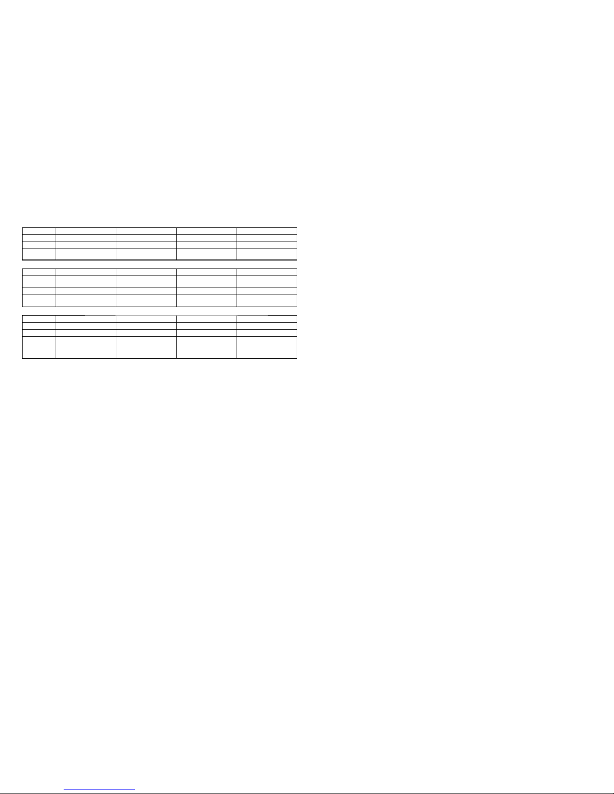
Model information table
Model SLT-A65 SLT-A65K SLT-A65L SLT-A65M
Destination AEP, CH AEP, CH AEP AEP, CH
GPS
– – – –
Lens
– DT 18-55mm
F3.5-5.6 SAM
DT 18-55mm
F3.5-5.6 SAM II
DT 18-135mm
F3.5-5.6 SAM
Model SLT-A65V SLT-A65VK SLT-A65VL SLT-A65VM
Destination US, CND, AEP, UK,
E, KR, AUS, J
US, AEP, UK, E,
KR, AUS, JE, J
US, AEP, UK, E,
KR,
AUS, JE, J
US, AEP, E
GPS
999 9
Lens – DT 18-55mm
F3.5-5.6 SAM
DT 18-55mm
F3.5-5.6 SAM II
DT 18-135mm
F3.5-5.6 SAM
Model SLT-A65VX SLT-A65VY SLT-A65X SLT-A65Y
Destination AEP, E, AUS, J AEP, E, KR, AUS, J AEP AEP
GPS
9 9
– –
Lens DT 18-55mm
F3.5-5.6 SAM II/
DT
55-200mm
F4-5.6 SAM
DT 18-55mm
F3.5-5.6 SAM/
DT 55-200mm
F4-5.6 SAM
DT 18-55mm
F3.5-5.6 SAM II/
DT 55-200mm
F4-5.6 SAM
DT 18-55mm
F3.5-5.6 SAM/
DT 55-200mm
F4-5.6 SAM
• Abbreviation
AUS : Australian model
CH : Chinese model
CND : Canadian model
J : Japanese model
JE : Tourist Model
KR : Korea model
The changed portions from
Ver. 1.5 are shown in blue.
Ver. 1.6 2013.07
SLT-A65/A65K/A65L/A65M/A65V/A65VK/A65VL/A65VM/A65VX/A65VY/A65X/A65Y_L2
– 4 –
SAFETY-RELATED COMPONENT WARNING!!
COMPONENTS IDENTIFIED BY MARK 0 OR DOTTED LINE WITH
MARK 0 ON THE SCHEMATIC DIAGRAMS AND IN THE PARTS LIST
ARE CRITICAL TO SAFE OPERATION. REPLACE THESE COMPONENTS WITH SONY PARTS WHOSE PART NUMBERS APPEAR AS
SHOWN IN THIS MANUAL OR IN SUPPLEMENTS PUBLISHED BY
SONY.
ATTENTION AU COMPOSANT AYANT RAPPORT
À LA SÉCURITÉ!
LES COMPOSANTS IDENTIFIÉS PAR UNE MARQUE 0 SUR LES
DIAGRAMMES SCHÉMATIQUES ET LA LISTE DES PIÈCES SONT
CRITIQUES POUR LA SÉCURITÉ DE FONCTIONNEMENT. NE REMPLACER CES COMPOSANTS QUE PAR DES PIÈCES SONY DONT
LES NUMÉROS SONT DONNÉS DANS CE MANUEL OU DANS LES
SUPPLÉMENTS PUBLIÉS PAR SONY.
Caution
Danger of explosion if battery is incorrectly replaced.
Replace only with the same or equivalent type.
Dispose of used batteries according to the instructions.
Caution
電池の交換は,正しく行わないと破裂する恐れがあります。
電池を交換する場合には必ず同じ型名の電池又は同等品と
交換してください。
使用済み電池は,取扱指示に従って処分してください。
CHEMICALS
Some chemicals used for servicing are highly volatile.
Their evaporation caused by improper management affects your health
and environment, and wastes resources.
Manage the chemicals carefully as follows.
• Store chemicals sealed in a specific place to prevent from exposure
to high temperature or direct sunlight.
• Avoid dividing chemicals into excessive numbers of small containers
to reduce natural evaporation.
• Keep containers sealed to avoid natural evaporation when chemicals
are not in use.
• Avoid using chemicals as much as possible. When using chemicals,
divide only required amount to a small plate from the container and
use up it.
EXTERIOR PARTS
Be careful to the following points for plastic parts used in this unit.
• Use a piece of cleaning paper or cleaning cloth for cleaning plastic
parts. Avoid using chemicals.
Even if you have to use chemicals to clean heavy dirt, don’t use paint
thinner, ketone, nor alcohol.
• Insert the specific screws vertically to the part when installing a
plastic part.
Be careful not to tighten screws too much.
SAFETY CHECK-OUT
After correcting the original service problem, perform the following
safety checks before releasing the set to the customer.
各種薬品の取り扱いについて
現在使用されている薬品の中には揮発性の高い薬品もありま
す。
それらを不用意に取り扱い蒸発させてしまうと,環境や健康へ
影響を与えたり,資源の無駄使いになります。
各種薬品は,下記の点に注意して取り扱ってください。
・ 保管場所を定め,高温になったり直射日光の当たらない場
所に密閉して保管してください。
・ 小分け(ハンドラップ等)する数は必要最小限に留め,容器
による自然蒸発を防いでください。
・ 作業に使用しない時は,必ずキャップ等をして自然蒸発を
防いでください。
・ 薬品を使用する回数を極力少なくし,使用する場合は使用
する量だけ容器より出して受け皿に残さないようにしてく
ださい。
樹脂系部品の取り扱いについて
本機に使用されている樹脂系の部品は,下記の点に注意して取
り扱ってください。
・ 清掃には薬品を使用せず,清掃紙や清掃布を使用してくだ
さい。
やむを得ず汚れがひどくて薬品を使用する場合は,シン
ナー,ケトン,エーテルは使用しないでください。
・ 各部品の取り付けには指定されたねじを使用し,部品に対
して垂直に取り付けてください。
また,ねじを締め付ける時は,無理な力を加えないでくだ
さい。
サービス,点検時には次のことにご注意ください。
– ENGLISH – – JAPANESE –
1. Check the area of your repair for unsoldered or poorly-soldered
connections. Check the entire board surface for solder splashes and
bridges.
2. Check the interboard wiring to ensure that no wires are “pinched”
or contact high-wattage resistors.
3. Look for unauthorized replacement parts, particularly transistors,
that were installed during a previous repair. Point them out to the
customer and recommend their replacement.
4. Look for parts which, through functioning, show obvious signs of
deterioration. Point them out to the customer and recommend their
replacement.
5. Check the B+ voltage to see it is at the values specified.
6. Flexible Circuit Board Repairing
• Keep the temperature of the soldering iron around 350°C during
repairing.
• Do not touch the soldering iron on the same conductor of the circuit
board (within 3 times).
• Be careful not to apply force on the conductor when soldering or
unsoldering.
UNLEADED SOLDER
This unit uses unleaded solder.
Boards requiring use of unleaded solder are printed with the lead free
mark (LF) indicating the solder contains no lead.
(Caution: Some printed circuit boards may not come printed with the
lead free mark due to their particular size.)
: LEAD FREE MARK
Be careful to the following points to solder or unsolder.
• Set the soldering iron tip temperature to 350°C approximately.
If cannot control temperature, solder/unsolder at high temperature
for a short time.
Caution: The printed pattern (copper foil) may peel away if the
heated tip is applied for too long, so be careful!
Unleaded solder is more viscous (sticky, less prone to
flow) than ordinary solder so use caution not to let solder
bridges occur such as on IC pins, etc.
• Be sure to control soldering iron tips used for unleaded solder and
those for leaded solder so they are managed separately. Mixing
unleaded solder and leaded solder will cause detachment phenomenon.
1. 注意事項をお守りください。
サービスのとき特に注意を要する個所については,キャビ
ネット,シャーシ,部品などにラベルや捺印で注意事項を
表示しています。これらの注意書きおよび取扱説明書等の
注意事項を必ずお守りください。
2. 指定部品のご使用を
セットの部品は難燃性や耐電圧など安全上の特性を持った
ものとなっています。従って交換部品は,使用されていた
ものと同じ特性の部品を使用してください。特に回路図,
部品表に0印で指定されている安全上重要な部品は必ず指
定のものをご使用ください。
3. 部品の取付けや配線の引きまわしはもとどおりに
安全上,チューブやテープなどの絶縁材料を使用したり,
プリント基板から浮かして取付けた部品があります。また
内部配線は引きまわしやクランパによって発熱部品や高圧
部品に接近しないよう配慮されていますので,これらは必
ずもとどおりにしてください。
4. サービス後は安全点検を
サービスのために取外したネジ,部品,配線がもとどおり
になっているか,またサービスした個所の周辺を劣化させ
てしまったところがないかなどを点検し,安全性が確保さ
れていることを確認してください。
5. チップ部品交換時の注意
・ 取外した部品は再使用しないでください。
・ タンタルコンデンサのマイナス側は熱に弱いため交換時
は注意してください。
6. フレキシブルプリント基板の取扱いについて
・ こて先温度を約350℃に設定して行ってください。
・ 同一パターンに何度もこて先を当てないでください。
(3回以内)
・ パターンに力が加わらないよう注意してください。
無鉛半田について
本機には無鉛半田が使用されています。
無鉛半田を使用している基板には,無鉛(LeadFree)を意味する
レッドフリーマークがプリントされています。
(注意:基板サイズによっては,無鉛半田を使用していてもレッ
ドフリーマークがプリントされていないものがありま
す)
:レッドフリーマーク
無鉛半田は,下記の点に注意して使用してください。
・ 半田こてのこて先温度は約350℃に設定してください。
温度調節が無理な場合は,高温短時間で作業を行ってくだ
さい。
注意:半田こてを長く当てすぎると,基板のパターン(銅
箔)がはがれてしまうことがありますので,注意して
ください。また,従来の半田よりも粘性が強いため,
IC端子などが半田ブリッジしないように注意してく
ださい。
・ 半田こてのこて先は,必ず無鉛半田用と有鉛半田用に分け
て管理してください。
無鉛半田と有鉛半田が混在すると剥離現象が発生してしま
います。
SLT-A65/A65K/A65L/A65M/A65V/A65VK/A65VL/A65VM/A65VX/A65VY/A65X/A65Y_L2
1-1
1. SERVICE NOTE
– ENGLISH –
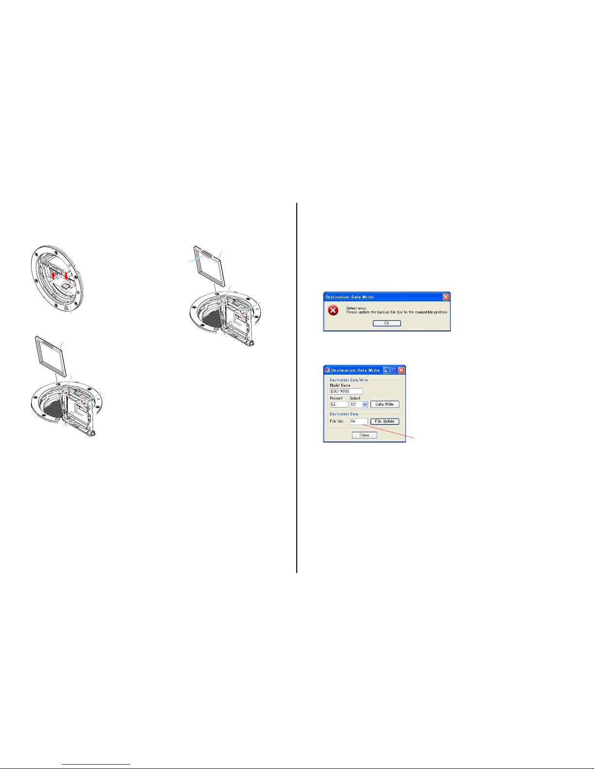
1-1. METHOD FOR REPLACING THE P.O.I.
Method of Removal
(1) Press the MB Mirror Frame Holder Lock SP to raise the P.O.I.
MB Mirror Frame Holder Lock SP
(2) Unjoint the two claws while pressing the P.O.I. backward.
Claw
Claw
P.O.I.
Method of Attachment
(1) When attaching the P.O.I., make the concave side of it face the
front and attach it downward.
Claw
Claw
P.O.I.
Concave side
The changed portions from
Ver. 1.1 are shown in blue.
Ver. 1.2 2012.04
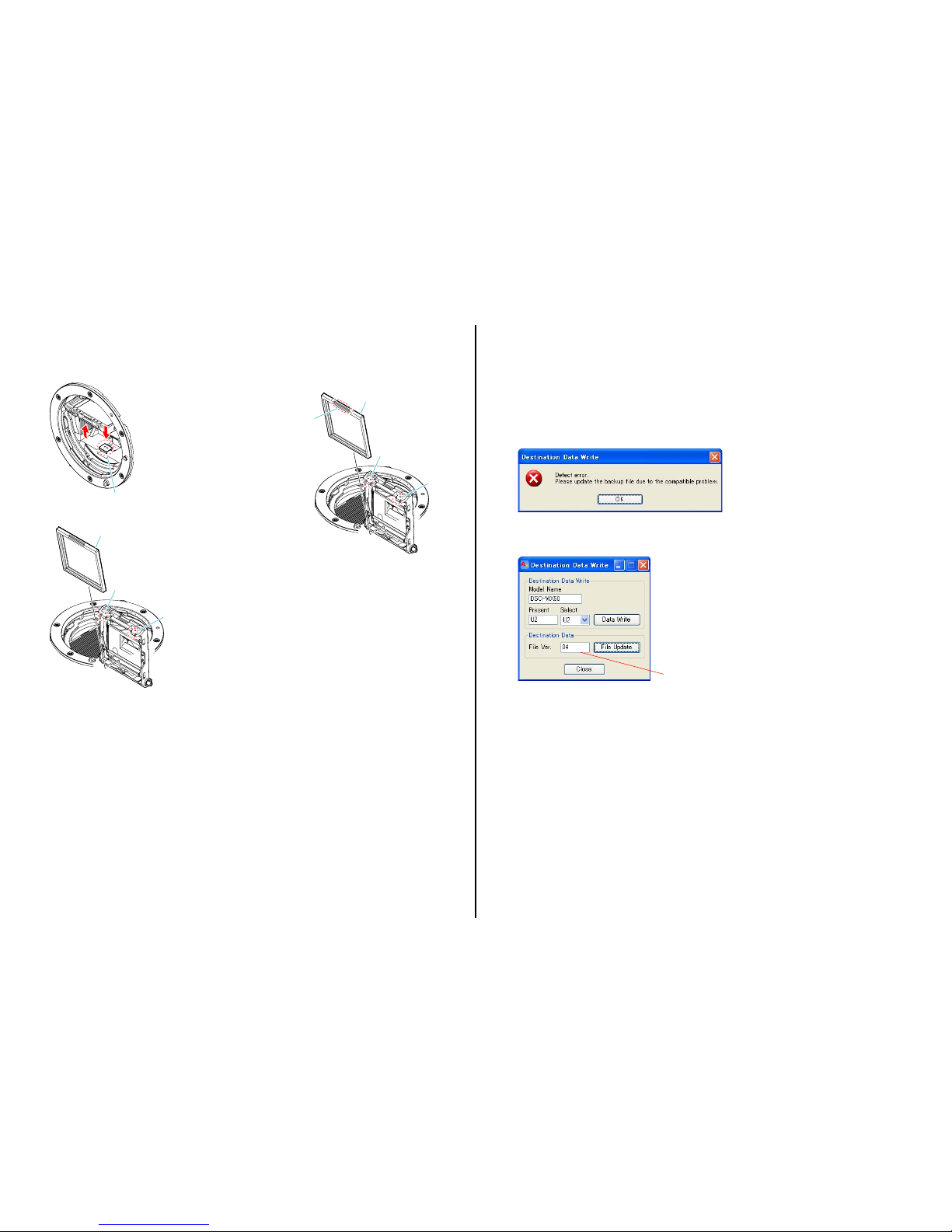
1-2. ADDITION OF DESTINATION DATA FILE
If the Destination Data file included in the Adjust manual is old, “DESTINATION DATA WRITE” cannot be executed in some cases.
In that case, download a new Destination Data file from the TISS homepage according to the following procedure.
Note 1: To perform Destination Data Write for this model, the Adjust manual of the DSC-WX50 series must have been installed.
Install the Adjust manual of the DSC-WX50 series in advance.
Note 2: The actual image may differ from the image shown above.
1) If the Destination Data file in the Adjust manual in use is old, the window shown in Fig. 1 is displayed.
Click the [OK] button.
Fig. 1
2) The Destination Data Write window opens.
Check the version of the Destination Data file retained in the Adjust manual.
Destination Ver. window
SLT-A65/A65K/A65L/A65M/A65V/A65VK/A65VL/A65VM/A65VX/A65VY/A65X/A65Y_L2
1-2
– ENGLISH –
Ver. 1.2 2012.04
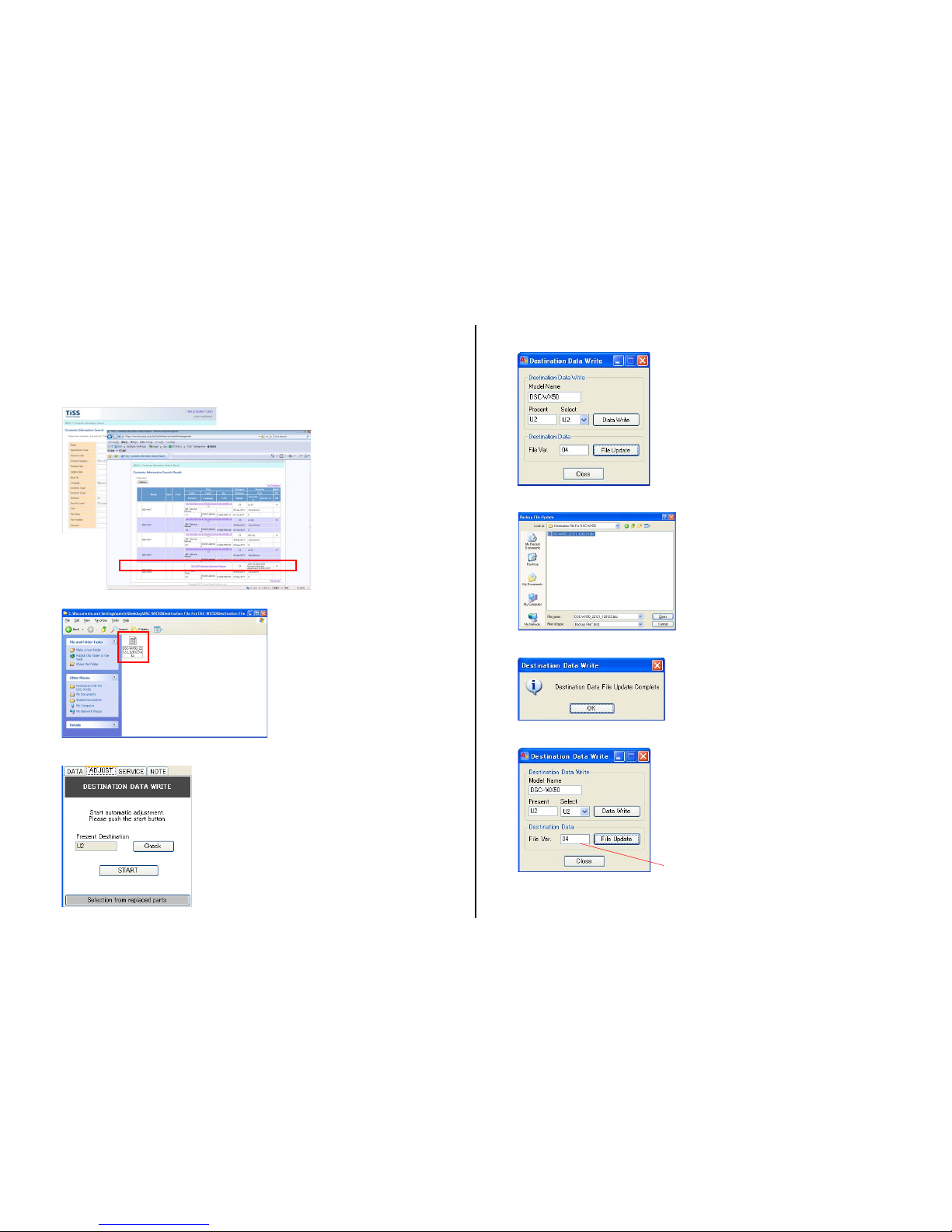
3) Search the model whose new Destination Data file you want to get on the TISS homepage.
When the Destination Data file has been updated, a file with a name “Destination File For ‘model name’.zip” is registered.
(Example) Destination File For DSC-WX50.zip
Furthermore, the version supported by the Destination Data file is shown in the Remarks column.
Note : If the Destination Data file has not been updated, contact the Service Headquarters.
4) Download the Destination Data file of the relevant model and unzip the file.
5) Execute “DESTINATION DATA WRITE” in the Adjust tab of the Adjust manual.
Click the [START] button.
6) Click the [File Update] button in the window.
7) A file selection screen opens. Select the Destination Data file to be added and click the [Open] button.
8) When the file has been successfully added, the following window opens.
9) Check the Destination Ver. window and confirm that the version has been updated.
Destination Ver. window
SLT-A65/A65K/A65L/A65M/A65V/A65VK/A65VL/A65VM/A65VX/A65VY/A65X/A65Y_L2
1-3
1-3. PRECAUTION ON REPLACING THE AM-026 BOARD
Destination Data
When you replace to the repairing board, the written destination data of repairing board also might be changed to original setting.
USB Serial No.
The set is shipped with a unique ID (USB Serial No.) written in it.
This ID has not been written in a new board for service, and therefore it must be entered after the board replacement.
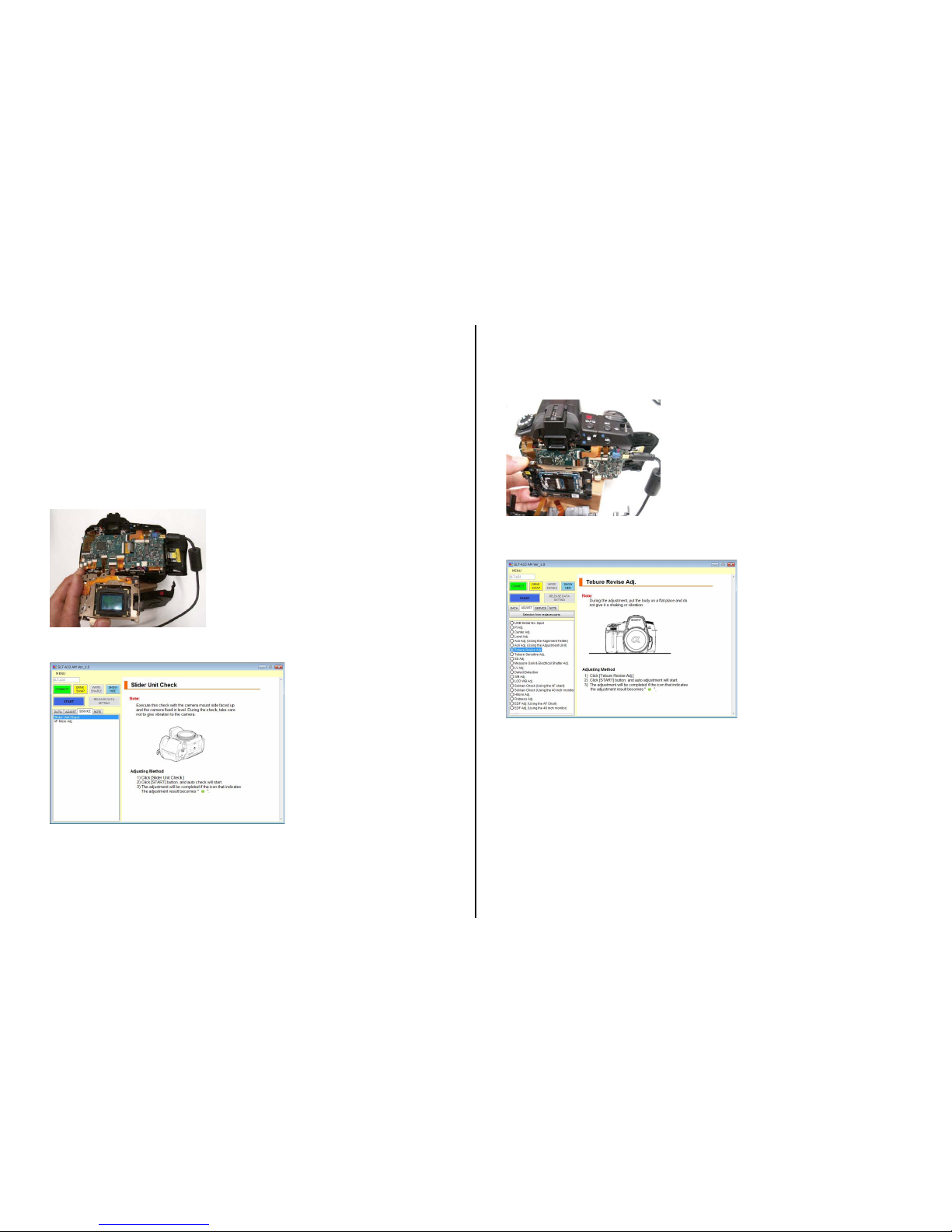
1-4. METHOD FOR CHECKING THE AS SLIDER UNIT (870)
Make sure to confirm below before replacing the AS Slider B Assy or the AS Holder Actuator Assy.
(1) Remove the CV Rear Cover Assy (870), and temporally mount the AS Slider Unit (870).
(2) Set the AS Slider Unit (870) upwards as shown in figure, and put it on a stable place.
(3) Select “Slider Unit Check” of the adjustment software, and then confirm the movement to the directions of Pitch and Yaw, and if an error occurs,
replace it with the component part corresponding to the movement.
The changed portions from
Ver. 1.1 are shown in blue.
Ver. 1.2 2012.04
– ENGLISH –
1-5. METHOD FOR ADJUSTING THE TEBURE REVISE
Make sure to confirm below after replacing the AS Slider B Assy or the AS Holder Actuator Assy.
(1) Remove the CV Rear Cover Assy (870), temporally mount the AS Slider Unit (870) mounted with the Imager Sensor, and then set up the camera
body and hold the AS Slider Unit (870) as shown in figure.
(2) Select “Slider Unit Check” of the adjustment software, and then confirm if the result is OK.
(3) Select “Tebure Revise Adj.” of the adjustment software, and then confirm if the result is OK.
(4) Mount the AS Slider Unit (870) to the camera.
SLT-A65/A65K/A65L/A65M/A65V/A65VK/A65VL/A65VM/A65VX/A65VY/A65X/A65Y_L2
1-4
– ENGLISH –
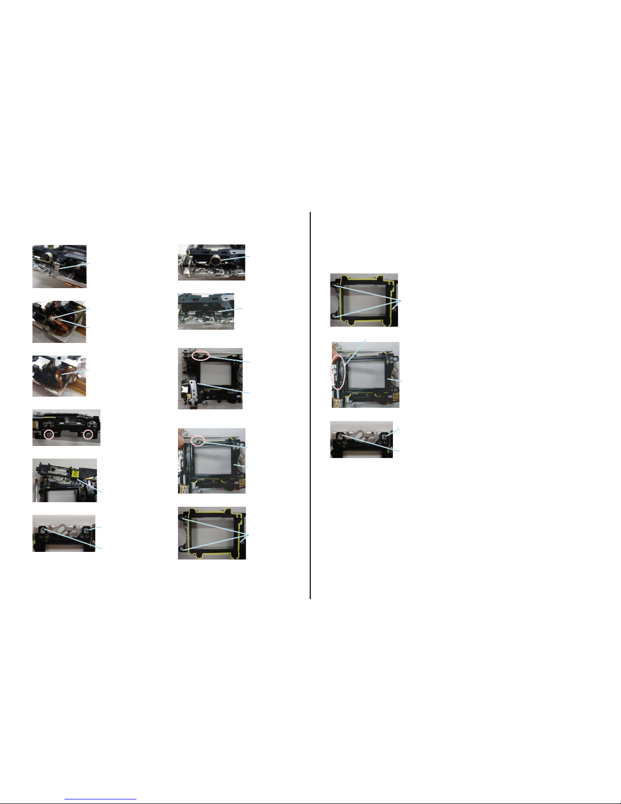
1-6. METHOD FOR REPLACING THE AS SLIDER B ASSY
Removal Procedure
(1) Remove the spring.
Spring
(2) Remove the solder on the enamel wires at two places.
Solde
r
Solde
r
(3) Remove the flexible board from the AS Slider B Assy.
Flexible Board
(4) Remove the two screws.
(5) Remove the AS Unit Holder Ball.
AS Unit Holder Ball
(6) Remove the two Ball Bearings.
Ball Bearing
Ball Bearing
(7) Remove the Cap SPs (for Pitch and Yaw).
Cap SP
(8) Remove the Caps (for Pitch and Yaw).
Cap
(9) Remove the AS Slider A Assy.
It can be done easily if A is removed beforehand.
AS Slider A Ass
y
A
(10) Remove the AS Slider B Assy.
It can be done easily if B is removed beforehand.
AS Slider B Ass
y
B
(11) Remove the three Ball Bearings.
Ball Bearing
The changed portions from
Ver. 1.1 are shown in blue.
Ver. 1.2 2012.04
Assembly Procedure
Note: Make sure to perform the assembly procedures after assembling the AS Holder Actuator Assy.
The assembly procedure is the reverse of the removal procedure.
Apply grease to the portions indicated below
.
* After applying grease, attach the Ball Bearings.
Ball Bearing
G G-15
AS Slider B Ass
y
G G-15 and G G-116
* After applying grease, attach the Ball Bearings.
Ball Bearing
G G-15
Ball Bearing
G G-15
SLT-A65/A65K/A65L/A65M/A65V/A65VK/A65VL/A65VM/A65VX/A65VY/A65X/A65Y_L2
1-5
– ENGLISH –
1-8. GPS RECEIVING CHECK (SLT-A65V/A65VK/A65VL/A65VM/A65VX/A65VY)
After a part of set was replaced or after the set was assembled, check the reception of GPS signal.
1-7. METHOD FOR REPLACING THE AS HOLDER ACTUATOR ASSY
Removal Procedure
Note: Make sure to perform the removal procedures after removing the
AS Slider B Assy.
(1) Remove the solder on the enamel wires at two places.
Solde
r
(2) Remove the flexible board from the hook on the AS Holder Actuator
Assy.
Hoo
k
(3) Remove the four screws to remove the AS Holder Actuator Assy.
AS Holder Actuator Assy
Assembly Procedure
Note: Make sure to perform the assembly procedures before assembling
the AS Slider B Assy.
The assembly procedure is the reverse of the removal procedure.
Apply grease to the portions indicated below.
AS Holder Actuator Assy
G G-15 and G G-116
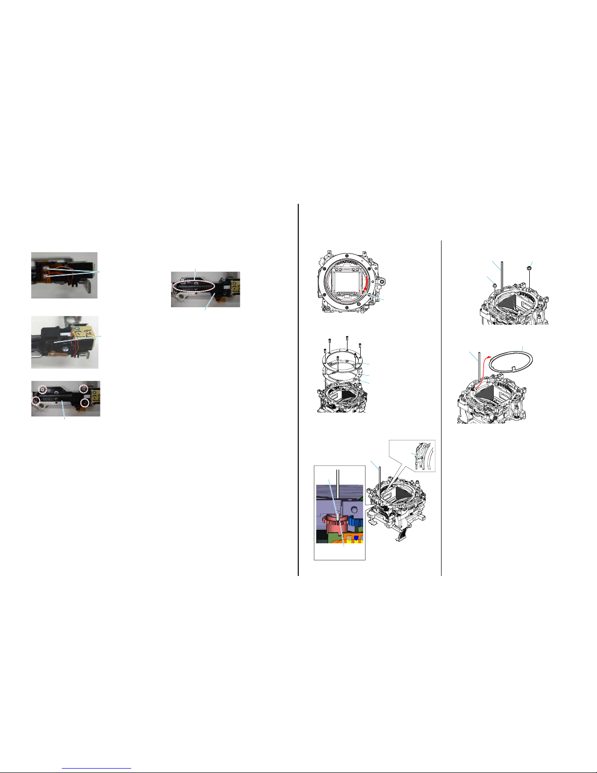
1-9. NOTE ON REMOVING THE AP IRIS RING
If the AP Iris Ring is removed, the aperture charge cannot be retained. Therefore, after removing the AP Iris Ring, retain the charge in the procedure
below.
(4) While keeping the pin inserted, remove the Ring Roller B (SV) and
AP Ring Roller C.
Pin
AP Ring Roller C
Ring Roller B (SV)
(5) While keeping the pin inserted, remove the AP Iris Ring.
Pin
AP Iris Ring
(1) Rotate clockwise the AP Iris Ring as far as it goes.
AP Iris Ring
(2) Remove the MB H Mount, MB Mount Spacer, and MB Ring SP COM,
unscrewing six screws.
MB Mount Spacer
MB ring SP COM
MB H mount
(3) Insert the pin (approx. 1mm in diameter) through the hole of front
frame and drop the tip of pin in the cut portion of AP Sensor Gear to
fix the AP Sensor Gear.
Pin
Pin
Cut portion of
AP Sensor Gear
Hole of front
frame
The changed portions from
Ver. 1.5 are shown in blue.
Ver. 1.6 2013.07
SLT-A65/A65K/A65L/A65M/A65V/A65VK/A65VL/A65VM/A65VX/A65VY/A65X/A65Y_L2
1-6
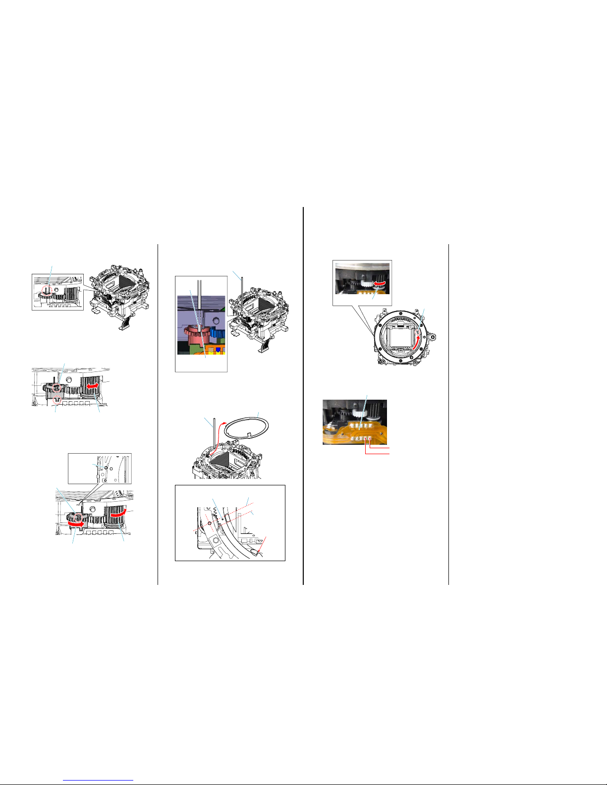
1-10. HOW TO CHARGE THE APERTURE
When installing the AP Aperture Unit, charge the aperture in the procedure below.
(1) Confirm that the arm of spring is free (initial position).
Spring is free
(initial position)
(2) Align the cut portion of AP Sensor Gear with the cut portion of side
charge plate by moving the AP Torque Limiter Assy.
AP Torque Limiter Assy
Cut portion of
AP Sensor Gear
Cut portion of side
charge plate
(3) Align the hole of front frame with the cut portion of AP Sensor Gear
by turning counterclockwise the AP Torque Limiter Assy to turn the
AP Sensor Gear 3 rotations (approx. 1000 degrees).
Cut portion of
AP Sensor Gear
Turn the AP Sensor Gear 3 rotations
Hole of front
frame
AP Torque Limiter Assy
(4) Insert the pin (approx. 1mm in diameter) through the hole of front
frame and drop the tip of pin in the cut portion of AP Sensor Gear to
fix the AP Sensor Gear.
Pin
Pin
Cut portion of
AP Sensor Gear
(5) While keeping the pin inserted, install the AP Aperture Unit, aligning
the mark of AP Aperture Ring with the center (the position where the
mark is overlapped within the range in the figure of projection) of limit
gear assembly.
Pin
The gap exists.
This line is parallel
and contacts the
right side of projection.
This line orients toward the
center of front frame.
The mark of AP Iris Ring should
be in between two parallel lines.
AP Iris Ring
The changed portions from
Ver. 1.1 are shown in blue.
Ver. 1.2 2012.04
(1) Rotate the AP Iris Ring as far as it goes by rotating clockwise the AP
Torque Limiter Assy.
AP Iris Ring
AP Torque Limiter Assy
(2) Measure the resistance between LN8201 and LN8202 on the AP-037
Flexible Board and confirm that the resistance is 100 to 450 Ω.
LN8202
AP-037
Flexible Board
LN8201
1-11. METHOD OF CONFIRMING THE PHASES OF AP IRIS RING AND AP SENSOR GEAR
After installing the AP Iris Ring, confirm the phases of AP Iris Ring and AP Sensor Gear in the following procedure.
– ENGLISH –
SLT-A65/A65K/A65L/A65M/A65V/A65VK/A65VL/A65VM/A65VX/A65VY/A65X/A65Y_L2
1-7
– JAPANESE –
1-1. P.O.I.の交換方法
取り外し方
(1) MBミラー枠ホルダ係止SPを押し,P.O.I.をアップしてくだ
さい。
MBミラー枠ホルダ係止SP
(2) P.O.I.を奥へ押しながらツメ2箇所を取り外してください。
ツメ
ツメ
P.O.I.
組み付け方
(1) P.O.I.を組み付ける際,下図のようにP.O.I.へこみ部が手前,
下向きとなるように取り付けてください。
ツメ
ツメ
P.O.I.
へこみ部
The changed portions from
Ver. 1.1 are shown in blue.
Ver. 1.2 2012.04
1-2. DestinationDataファイルの追加について
Adjustmanualに含まれるDestinationDataファイルが古い場合,「DESTINATIONDATAWRITE」が実行できないことがあります。
その場合は,下記の手順を参考にして,TISSホームページより新しいDestinationDataファイルを入手してください。
Note1: この機種で仕向け設定を行うには,DSC-WX50シリーズのAdjustmanualがインストールされている必要があります。
先にDSC-WX50シリーズのAdjustmanualをインストールしてください。
Note2: 手順中の画像は実際と異なる場合があります。
1) 使用しているAdjustmanualのDestinationDataファイルが古い場合,Fig.1のようなウインドウが表示される。
[OK]ボタンをクリックする。
Fig. 1
2) DestinationDataWriteウインドウが表示される。
Adjustmanualの保持しているDestinationDataファイルのバージョンを確認する。
Destination Ver. ウインドウ
 Loading...