

Sony SF-F1 Service manual
SF-F1
SERVICE MANUAL
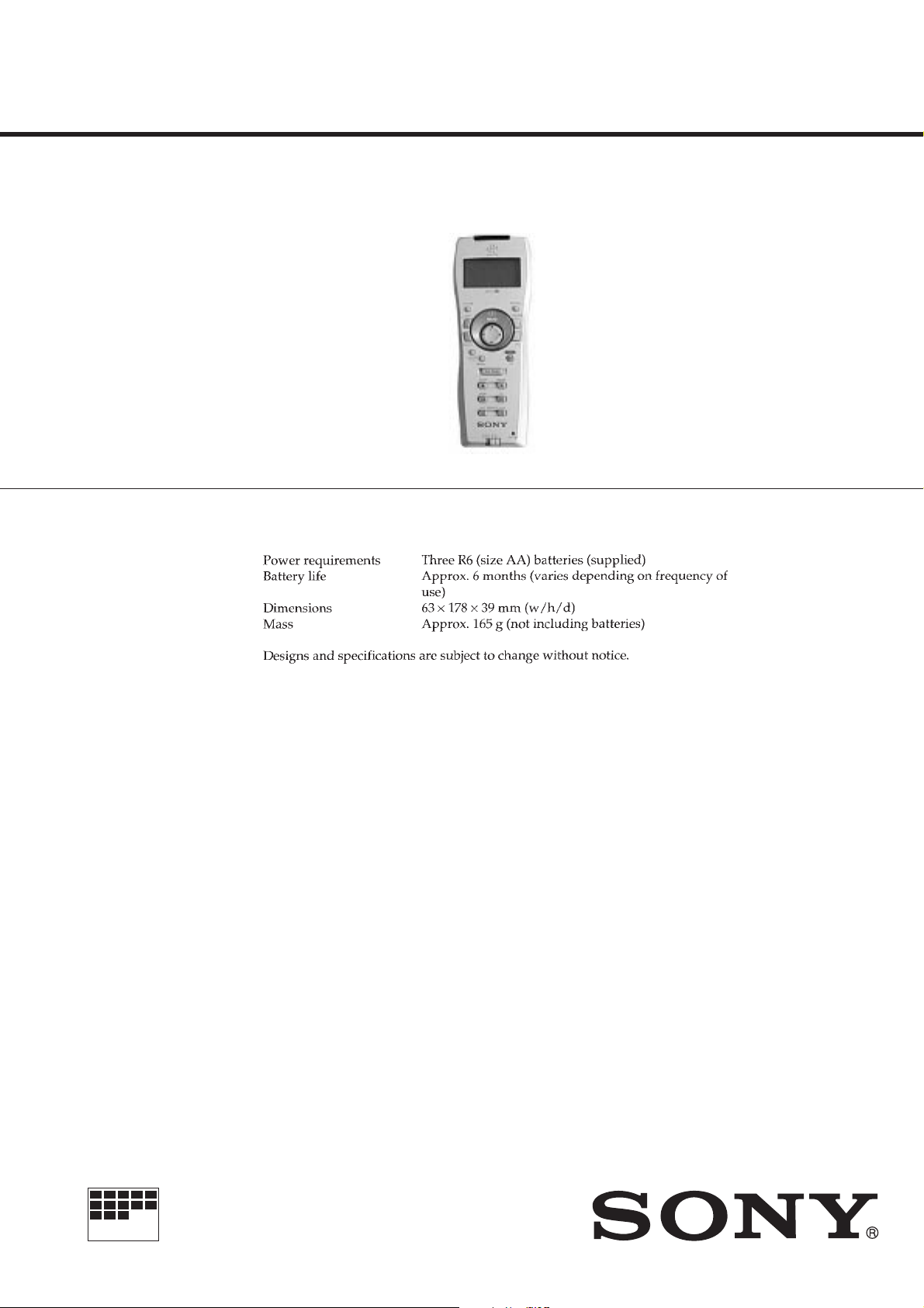
SPECIFICATIONS
AEP Model
EAST EUROPE Model
MICROFILM
SMART FILE FINDER

TABLE OF CONTENTS
1. GENERAL ...................................................................1-1
Table of contents······························································1-1
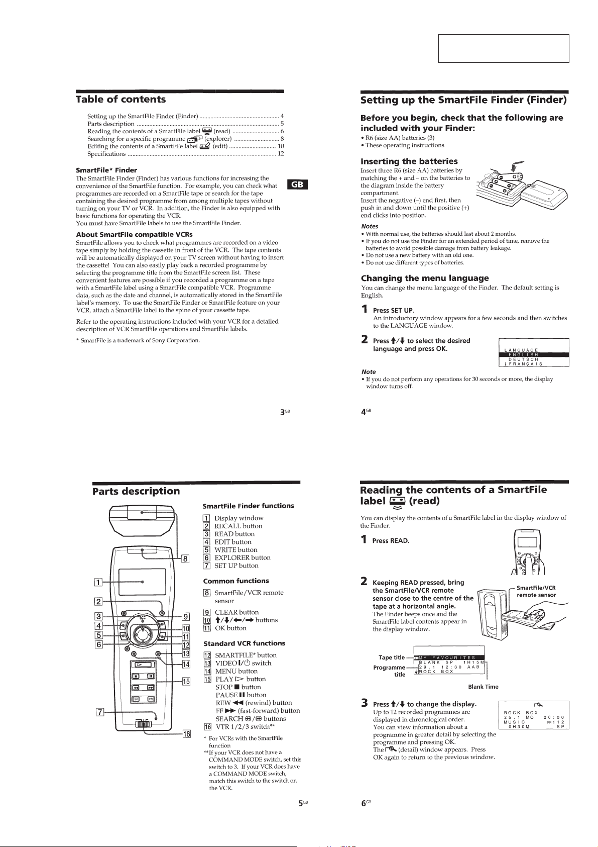
Setting up the SmartFile Finder (Finder) ························ 1-1
Parts description ······························································1-1
Reading the contents of a SmartFile label (read) ············1-1
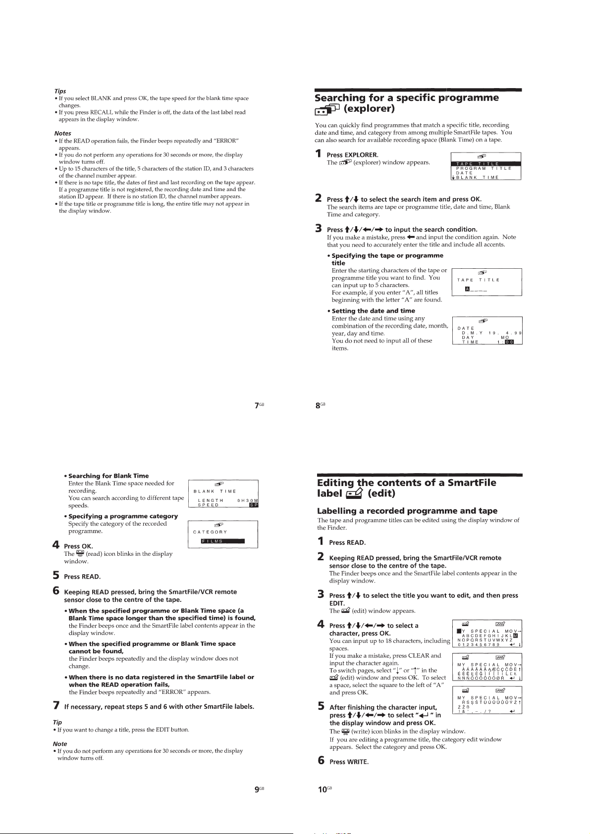
Searching for a specific programme (explorer)···············1-2
Editing the contents of a SmartFile label (edit)···············1-2
2. PRINTED WIRING BOARDS AND SCHEMATIC
DIAGRAMS ..........................................................2-1
• PRINTED WIRING BOARD
(SMART FILE CONTROL) ·········································2-3
• SCHEMATIC DIAGRAM
(SMART FILE CONTROL) ·········································2-5
• SCHEMATIC DIAGRAM
(SERIAL TRANSFER CONTRLOL/ANTENNA)······2-7
• PRINTED WIRING BOARD
(SERIAL TRANSFER CONTROL/ANTENNA) ········2-9
3. REPAIR PARTS LIST
3-1. EXPLODED VIEW·························································3-1
3-1-1.SMART FILE FINDER SECTION ·································3-1
3-2. ACCESSORIES ······························································3-2
SAFETY CHECK-OUT
After correcting the original service problem, perform the following
safety checks before releasing the set to the customer.
1. Check the area of your repair for unsoldered or poorly-soldered
connections. Check the entire board surface for solder splashes
and bridges.
2. Check the interboard wiring to ensure that no wires are
"pinched" or contact high-wattage resistors.
3. Look for unauthorized replacement parts, particularly
transistors, that were installed during a previous repair . Point
them out to the customer and recommend their replacement.
4. Look for parts which, through functioning, show obvious signs
of deterioration. Point them out to the customer and
recommend their replacement.
5. Check the B+ voltage to see it is at the values specified.
6. Flexible Circuit Board Repairing
• Keep the temperature of the soldering iron around 270˚C
during repairing.
• Do not touch the soldering iron on the same conductor of the
circuit board (within 3 times).
• Be careful not to apply force on the conductor when soldering
or unsoldering.
— 2 —
SECTION 1
GENERAL
SF-F1
This section is extracted from
instruction manual.
1-1
1-2
 Loading...