

Sony SERVICE MANUAL Service Manual
Ver. 1.0 1998.07
MICROFILM
CFS-515L
SERVICE MANUAL
RADIO CASSETTE-CORDER
SPECIFICATIONS
East European Model
Model Name Using Similar Mechanism NEW
Tape Transport Mechanism Type MF-W495-117
Frequency range FM : 65 – 108MHz
MW : 531 – 1,602kHz
LW : 153 – 279kHz
SW : 5.95 – 18MHz
IF FM : 10.7MHz
MW/LW/SW : 455kHz
Aerials FM/SW : Telescope
MW/LW : Built-in ferrite bar
Recording system 4-track, 2-channel stereo
Frequency response 70 – 13,000Hz
Speakers Full range : 10cm (4 inches) dia., 6ohms,
cone type/Tweeter : 2cm (13/16 inches) dia.
Output Headphones jack (stereo minijack), for
16 – 68 ohms impedance headphones
Maximum Power output
5W+5W
Battery life FM Recording : Sony R20P : Approx. 10hours/
Sony LR20 alkaline : Approx. 20hours
Playback : Sony R20P : Approx. 3.5hours/
Sony LR20 alkaline : Approx. 8hours
Power requirements 230V AC, 50Hz
9V DC, six R20 (size D) batteries
Power consumption AC 18 W
Dimensions Approx. 697 x 211 x 201.5 mm (w/h/d)
(27 1/2 x 8 3/8 x 8 inches) incl. projecting parts and
controls, not incl. handle
Mass Approx. 6.2 kg (13 lb 10 oz) incl. batteries
Supplied accessories
AC power cord (1)
Design and specifications are subject to change without notice.

– 2 –
Specifications ........................................................................... 1
1. GENERAL
Looking at the Controls ..................................................... 3
2. DISASSEMBLY
2-1. Cabinet (Front) Section,
Cabinet (Rear) Section ................................................ 4
2-2. BATT (–) Board, BATT (+) Board ............................. 4
2-3. Power (AC) Board, Power (DC) Board...................... 4
2-4. Mechanism Deck, REC SW Board............................. 5
2-5. Chassis Sub Assy, Belt................................................ 5
2-6. VOL Board, Main Board, ECM Board....................... 6
2-7. Tuner Board ................................................................ 6
3. DIAL POINTER INSTALLATION ............................7
4. ADJUSTMENTS
4-1. Mechanical Adjustments ............................................ 8
4-2. Electrical Adjustments................................................ 8
5. DIAGRAMS
5-1. Block Diagram...........................................................11
5-2. Printed Wiring Boards – Main Section –.................. 14
5-3. Schematic Diagram – Main Section – ...................... 17
5-4. Printed Wiring Boards – Tuner Section –................. 20
5-5. Schematic Diagram – Tuner Section – ..................... 21
6. EXPLODED VIEWS
6-1. Cabinet (Rear) Section.............................................. 25
6-2. Cabinet (Front) Section ............................................ 26
6-3. Mechanism Deck Section -1..................................... 27
6-4. Mechanism Deck Section -2..................................... 28
6-5. Speaker Section ........................................................ 29
7. ELECTRICAL PARTS LIST.................................... 30
SAFETY-RELATED COMPONENT WARNING!!
COMPONENTS IDENTIFIED BY MARK ! OR DOTTED LINE
WITH MARK ! ON THE SCHEMATIC DIAGRAMS AND IN THE
PARTS LIST ARE CRITICAL TO SAFE OPERATION.
REPLACE THESE COMPONENTS WITH SONY PARTS WHOSE
PART NUMBERS APPEAR AS SHOWN IN THIS MANUAL OR IN
SUPPLEMENTS PUBLISHED BY SONY.
TABLE OF CONTENTS
• HOW TO CHANGED THE CERAMIC FILTERS
This model is used two ceramic filters of CF1 and CF2.
You must used same type of color marked ceramic filters in
order to meet same specifications.
Therefore, the ceramic filter must changed two pieces together
since it’s supply two pieces in one package as a spare parts.
Mark Center fequency
red
blue
orange
10.70MHz
10.67MHz
10.73MHz
mark
CF1, 2
– 3 –
SECTION 1
GENERAL
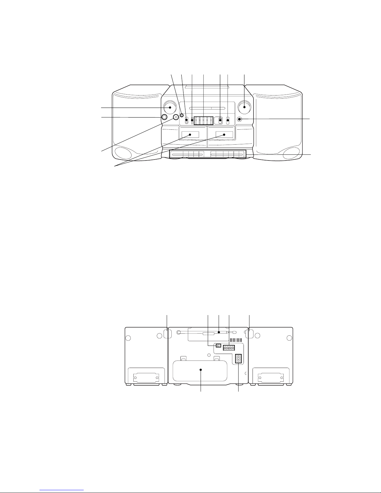
LOOKING AT THE CONTROLS
FRONT PANEL
REAR PANEL
5
67
1
2
3
4
!£
!¡89!º
!™
5
67
1234
1Cassette compartments
2 MIC (microphone)
3 PHONES (headphones) jack (stereo mini-jack)
4 VOLUME control
5 OPR/BATT (operation/battery) indicators
6 FUNCTION selector
RADIO
DUBBING HIGH
DUBBING NORM
TAPE/RADIO OFF
7 BALANCE control
8 5 BAND GRAPHIC EQUALIZER controls
9 PRESET MODE selector
!º BAND selector
!¡ TUNING control
!™ FINE TUNING control
!£ Tape operating buttons
r REC (record) button : Deck B only
( PLAY (playback) button
0 REW (rewind) button
) FF (fast-forward) button
p6 STOP/EJECT button
P PAUSE button
1 LOCK tab (right side)
2 FM MODE switch
3 Telescopic aerial
4 SPEAKER terminals
5 LOCK tab (Left side)
6 ⁄ AC IN (AC power input) socket
7 Battery compartment
– 4 –
SECTION 2
DISASSEMBLY
Note : Follow the disassembly procedure in the numerical order given.
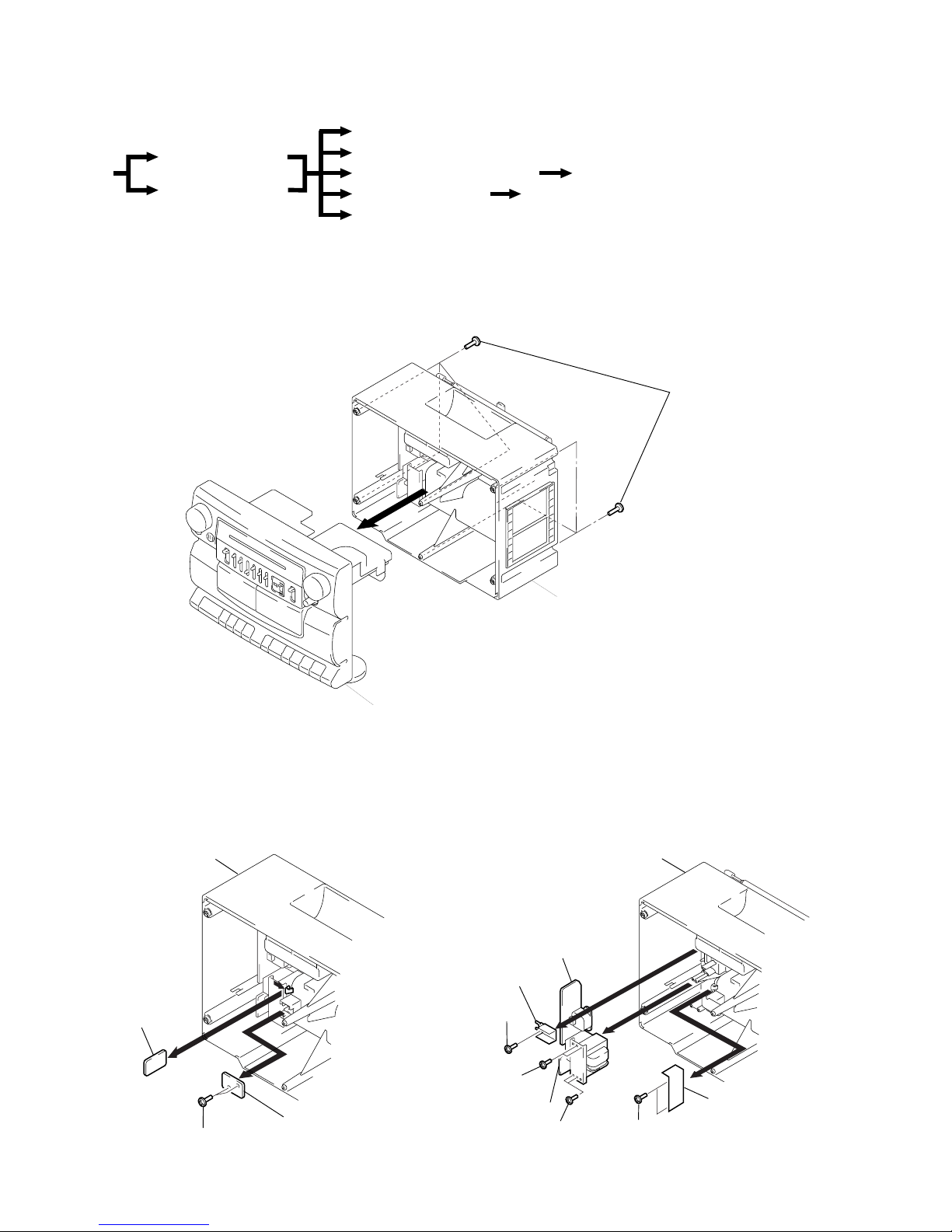
2-1. CABINET (FRONT) SECTION, CABINET (REAR) SECTION
2-2. BATT (–) BOARD, BATT (+) BOARD
r
The equipment can be removed using the following procedure.
Cabinet (Front) section
BATT (–) board, BATT (+) board
Cabinet (Rear) section
Set
Power (AC) board, Power (DC) board
Mechanism deck, REC SW board Chassis sub assy, Belt
VOL board, Main board ECM board
Tuner board
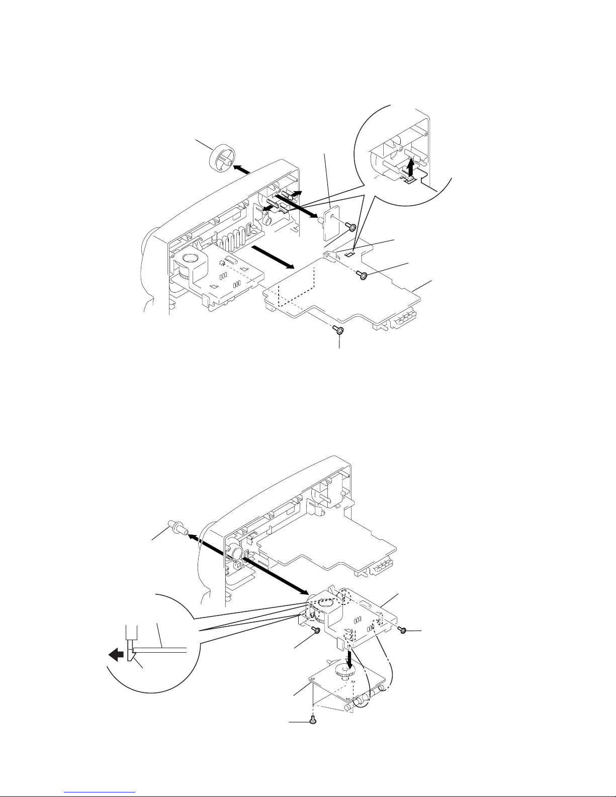
2-3. POWER (AC) BOARD, POWER (DC) BOARD
Cabinet (Rear) section
Bracket (AC)
5
Screws (+BTP 3x10)
3
Screws
(+BTP 3x10)
1
Screw
(+BTP 3x10)
2
4
6
Power (AC) board
Shield plate (T)
Power (DC) board
3
Screws
(+BTP 3x10)
Cabinet (Rear) section
1
Screws (+BTP 3x10)
3
4
2
BATT (+) board
BATT (–) board
Cabinet (Rear) section
1
Screws
(+BTP 3x14)
2
Cabinet (Front) section
– 5 –
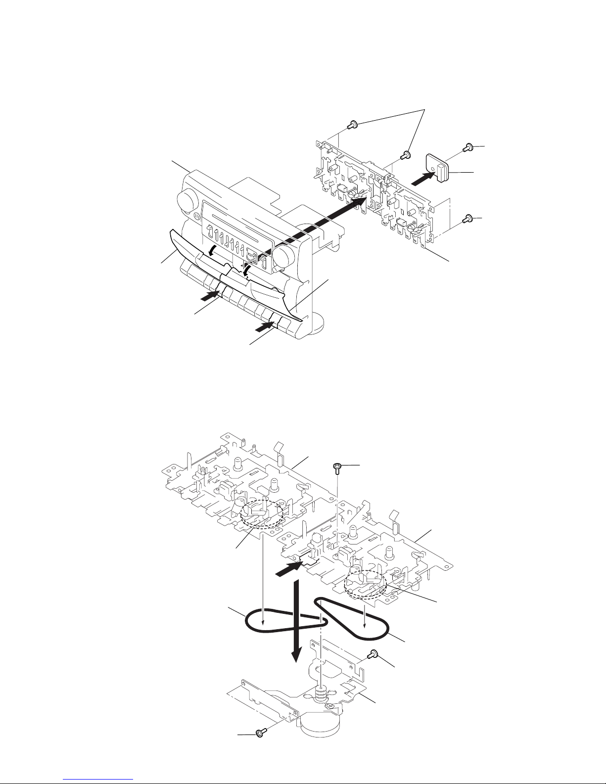
2-4. MECHANISM DECK, REC SW BOARD
2-5. CHASSIS SUB ASSY, BELT
2
Screw (+PTT 2x5)
1
3
Deck B
2
Screws (+PTT 2x5)
4
Belt
4
Belt
2
Screws (+PTT 2x5)
Deck A
Flywheel ass
y
Chassis sub assy
Flywheel assy
3
Screws
(+BTP 3x10)
3
Screws
(+BTP 3x10)
5
Screw
(+PTT 2x6)
6
4
1
2
1
Button (ST/EJ)
Cassette lid (L)
REC SW board
Cassette lid (R)
Mechanism deck section
Button (ST/EJ)
Cabinet (Front) section
2
– 6 –
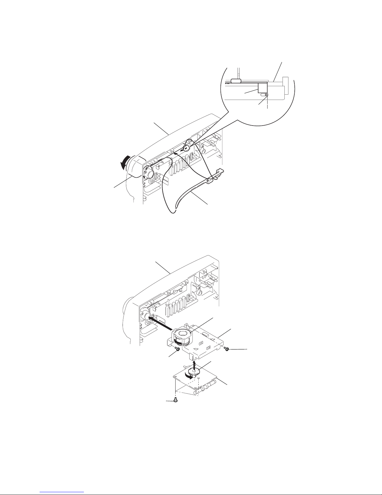
2-6. VOL BOARD, MAIN BOARD, ECM BOARD
2-7. TUNER BOARD
5
3
6
4
Screws (+BVTP 3x10)
1
Screw (+BTP 3x10)
1
Screw (+BTP 3x10
)
2
Knob (F/T)
Chassis (Tune)
Tuner board
Tuner board
Claw
7
1
3
3
4
8
5
Screw (+BTP 3x10)
6
Screw (+BVTP 3x6)
2
Screw
(+BTP 3x10)
Knob (VOL)
VOL board
Main board
ECM board
– 7 –
SECTION 3
DIAL POINTER INSTALLATION
Cabinet (Front)
Cabinet (Front)
Knob (Tune)
1
Pointer
a
c
b
Pointer
Marked line
2
– 1
2
– 2
6
Screw (+BTP 3x10
)
6
Screw (+BTP 3x10)
5
Screws (+BVTP 3x10)
Cabinet (Front)
4
Gear (Midway)
3
Gear (VC)
Chassis (Tune)
Tuner board
1 Set the pointer into the grooves of the cabinet
(Front) in the order of a, b and c.
2 Turn the knob (Tune) in the direction of the arrow,
then set the pointer by aligning it with the marked
line of the cabinet (Front).
3 Turn the gear (VC) fully counterclockwise.
4 Turn the gear (Midway) fully clockwise.
5 Mount the tuner board to the chassis and tighten
with screws.
6 Mount the chassis (Tune) to the cabinet (Front) and
tighten with screws.
Note : Follow the installation procedure in the numerical order given.
– 8 –
SECTION 4
ADJUSTMENTS
4-1. MECHANICAL ADJUSTMENTS
PRECAUTION
1. Clean the following parts with a denatured-alcohol-moistened
swab :
record/playback head playback head
pinch roller erase head
rubber belt capstan
2. Demagnetize the record/playback head with a head demagnetizer. (Do not bring the head demagnetizer close to the erase
head.)
3. Do not use a magnetized screwdriver for adjustments.
4. After the adjustments, apply suitable locking compound to the
parts adjusted.
5. The adjustments should be performed with the rated power supply voltage unless otherwise noted.
Torque Measurement
Torque Torque Meter Meter Reading
Playback CQ-102C
18 – 60 g • cm
(0.25 – 0.83 oz• inch)
Back Tension CQ-102C
1 – 5 g • cm
(0.014 – 0.069 oz• inch)
Rewind
CQ-201B
45 – 95 g • cm
Fast Forward (0.63 – 1.31 oz• inch)
Tape T ension Measurement
Mode Tension Meter Meter Reading
FWD CQ-403A more than 60g (2.12 oz)
4-2. ELECTRICAL ADJUSTMENTS
TAPE SECTION
1. The adjustments should be performed in the order give in the
service manual. (As a general rule, playbak circuit adjustment
should be completed before performing recording circuit adjustment.)
2. The adjustments should be performed for both L-CH and R-CH
unless otherwise indicated.
• Switch location
FUNCTION switch • • • • • • • • • • • • • • • • • TAPE (RADIO OFF)
PRESET MODE • • • • • • • • • • • • • • • • • • • • • MANUAL
GRAPHIC EQUALIZER • • • • • • • • center click
BALANCE • • • • • • • • • • • • • • • • • • • • • • • • • • • • • center click
VOLUME• • • • • • • • • • • • • • • • • • • • • • • • • • • • • • • MAX
MEGA BASS • • • • • • • • • • • • • • • • • • • • • • • • • mechanical center
Standard Output Level
Output terminal PHONES SP (FRONT) OUT
Load impedance 32Ω 6Ω
Output signal level 0.25V (–10dB) 0.775V (0dB)
Test T ape
Type Signal Used for
WS-48A 3kHz, 0dB Tape Speed Adjustment
0dB=0.775V
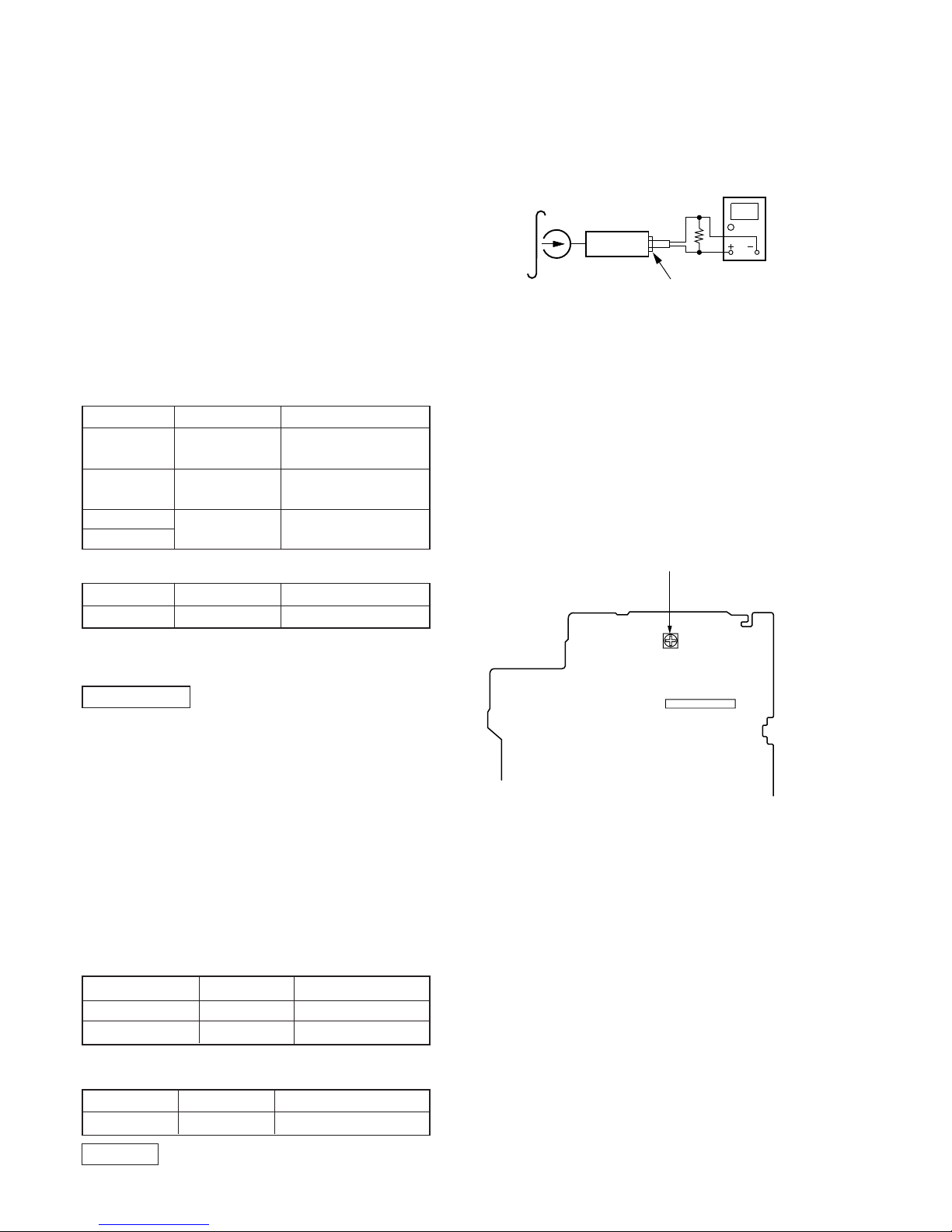
Tape Speed Adjustment
Procedure :
Mode : Playback
(Normal speed)
1. Deck A to playback mode.
2. Adjust the RV303 for 2,985 – 3,015Hz reading on digital frequency counter.
3. Frequency difference between the beginning and the end of the
tape should be within 1% (30Hz).
(High speed)
4. Deck B to record mode.
5. Deck A to high speed playback mode.
6. Confirm that the reading of the digital voltmeter becomes 5,500
– 6,500Hz.
7. Frequency difference between the beginning and the end of the
tape should be within 1% (30Hz).
Adjustment Location :
set
test tape
WS-48A
(3kHz, 0dB)
32
Ω
digital frequency
counter
phones jack
IC201
RV303 : Tape Speed Adjustment
[ MAIN BOARD ]
(Component side)
 Loading...