

Page 1

Screen
Management
System
Projectionist Terminal
4-291-777-14 (1)
User’s Guide
Software Version 2.50
© 2011 Sony Corporation
Page 2

NOTICE TO USERS
Program © 2009, 2011, 2012 / Documentation © 2009,
2011, 2012 Sony Corporation
All rights reserved. This manual or the software described
herein, in whole or in part, may not be reproduced,
translated or reduced to any machine readable form
without prior written approval from Sony Corporation.
SRX Controller
The SRX Controller application exercises direct control
over the projector via the projector’s serial control port.
Operations using the SRX Controller can be in conflict
with operations using the Projectionist Terminal or the
SMS Controller. The SRX Controller application should
not be used at the same time the Projectionist Terminal or
SMS Controller is in operation. Once changes using the
SRX Controller are completed, refresh the SMS Server
stored Projector data.
SONY CORPORATION PROVIDES NO
WARRANTY WITH REGARD TO THIS MANUAL,
THE SOFTWARE OR OTHER INFORMATION
CONTAINED HEREIN AND HEREBY EXPRESSLY
DISCLAIMS ANY IMPLIED WARRANTIES OF
MERCHANTABILITY OR FITNESS FOR ANY
PARTICULAR PURPOSE WITH REGARD TO THIS
MANUAL, THE SOFTWARE OR SUCH OTHER
INFORMATION. IN NO EVENT SHALL SONY
CORPORATION BE LIABLE FOR ANY
INCIDENTAL, CONSEQUENTIAL OR SPECIAL
DAMAGES, WHETHER BASED ON TORT,
CONTRACT, OR OTHERWISE, ARISING OUT OF
OR IN CONNECTION WITH THIS MANUAL, THE
SOFTWARE OR OTHER INFORMATION
CONTAINED HEREIN OR THE USE THEREOF.
Sony Corporation reserves the right to make any
modification to this manual or the information contained
herein at any time without notice.
The software described herein may also be governed by
the terms of a separate user license agreement.
Network Data Storage
When the Network Data Storage system for the facility
uses Microsoft Windows as the operating system it is
recommended that you use Network Files System (NFS)
for optimum performance in accessing files across the
network. Alternatively, SAMBA may be used for
connectivity between the SMS Server and the network
storage computer. SAMBA is a suite of applications that
provides seamless file sharing services to SMB/CIFS
clients, i.e., to Microsoft Windows.
If connectivity to the Network Data Storage is lost the
following steps should be taken.
• Verify the Network Data Storage system is working.
If connectivity issues still cannot be resolved it may be
necessary to remove and re-create the Network Storage
locations using the SMS Controller application. See
Settings/Folders on the SMS Controller for more
information.
If you are still unable to establish connectivity with the
Network Data Storage system, execute a system Power
OFF/ON. This will require Initializing Security.
Microsoft and Windows are registered trademarks of
Microsoft Corporation in the United States and/or other
countries. Adobe, Acrobat and Acrobat Reader are
trademarks of Adobe Systems Incorporated in the United
States and/or other countries. All other company and
product names are trademarks or registered trademarks of
the respective companies or their respective makers.
For projector specific information, refer to projector
manuals.
2
Page 3

Table of Contents
Chapter 1 User Guide
Overview...........................................................................................7
Login ...............................................................................................10
Basic Screen View.........................................................................11
Shows .............................................................................................13
Content ...........................................................................................30
Status Indicator Lamp ........................................................................... 7
Emergency Alert.................................................................................... 8
Playlist Elements ................................................................................... 8
Composition Playlist (CPL) .............................................................. 8
Show Playlist (SPL) .......................................................................... 8
Commands ........................................................................................ 8
Play While Ingest (PWI) ....................................................................... 9
Sony Trusted Circle............................................................................... 9
Logout ................................................................................................. 10
Base Screen ......................................................................................... 11
Menus .................................................................................................. 12
Now Showing ...................................................................................... 13
Show Controls ................................................................................ 15
Show Listing........................................................................................ 16
Play Show ....................................................................................... 17
View Show Details ......................................................................... 17
Manage Shows .................................................................................... 18
View Playlist Details ...................................................................... 19
Create Show Playlist (SPL) ............................................................ 20
Edit Show Playlist (SPL) ................................................................ 24
Delete Show Playlist (SPL) ............................................................ 27
Schedule .............................................................................................. 27
View Previous Day/Next Day ........................................................ 28
View Today .................................................................................... 28
Automation.......................................................................................... 28
GPI Trigger.......................................................................................... 29
Adding an SPL to the GPI-SPL List ............................................... 29
Deleting an SPL from the GPI-SPL list .......................................... 29
Content Listing .................................................................................... 30
Play Content ................................................................................... 31
Playing Back Play While Ingest Content ....................................... 31
View Content Details ...................................................................... 31
Transfer Status..................................................................................... 31
Table of Contents
3
Page 4

Manage DCPs...................................................................................... 33
Local Ingest ......................................................................................... 34
Network Ingest .................................................................................... 35
PWI (Play While Ingest) ..................................................................... 35
Cancel Play While Ingest ............................................................... 36
Ingest KDMs ....................................................................................... 36
View KDM Details ......................................................................... 37
Cleanup (KDMs) ............................................................................ 37
S2S Source .......................................................................................... 38
S2S Network Setup ............................................................................. 38
PWI (Play While Ingest) Source ......................................................... 39
Projector .........................................................................................40
Projector Control ................................................................................. 40
Set Projector LAMP OFF/ON ........................................................ 41
Douse the Projector ........................................................................ 41
Audio Muting ................................................................................. 41
Change Projector Function ............................................................. 42
Set Luminance Offset ..................................................................... 43
Function Setup..................................................................................... 43
Configure Function ......................................................................... 43
Projection Type ................................................................................... 46
Projector FUNCTION .................................................................... 47
Adjustment .......................................................................................... 47
Projection Type 2D ......................................................................... 47
Projection Type 3D ......................................................................... 49
Ghostbuster.......................................................................................... 51
Projector Remote Update .................................................................... 51
Status..............................................................................................52
Projector Status.................................................................................... 53
Power .............................................................................................. 53
Peltier - Thermal Devices ............................................................... 53
DVI signal, Ballast, RT Clock Battery ........................................... 53
Board, Lens, Electrical, AIr FIlter, Filter Duct .............................. 53
Connection and Battery .................................................................. 53
Lamp Status......................................................................................... 54
Lamp Information ........................................................................... 54
Lamp Indicators .............................................................................. 54
Fan Status ............................................................................................ 55
Subsystem Fans .............................................................................. 55
Projector Component Fans ............................................................. 55
Temperature Status.............................................................................. 56
Subsystem Temperature ................................................................. 56
Projector Component Temperatures ............................................... 56
Media Block Status ............................................................................. 56
Media Block State .......................................................................... 57
4
Table of Contents
Page 5

Process/Component ........................................................................ 57
Memory .......................................................................................... 57
Power Supplies ............................................................................... 57
Security ........................................................................................... 58
RAID Status ........................................................................................ 58
RAID Status .................................................................................... 58
HDD Status ..................................................................................... 58
DCP Space Used ............................................................................. 58
Logs ................................................................................................59
Maintenance ...................................................................................60
Projector .............................................................................................. 60
Refresh SMS Server ....................................................................... 61
Lamp Information ........................................................................... 62
Luminance Adjustment ................................................................... 62
Security (Role Restricted) ................................................................... 63
Marriage .............................................................................................. 64
Network Setup (Theater) ..................................................................... 64
Network Address Assignment ........................................................ 64
DNS Address Assignment .............................................................. 65
Time Zone ........................................................................................... 66
Clock Settings (Role Restricted) ......................................................... 67
Closed Caption Setup .......................................................................... 68
Owner Information (Role Restricted).................................................. 68
eCNA Settings (Role Restricted) ........................................................ 69
Restart SMS Server .......................................................................69
Restart SMS Server Application ......................................................... 69
System Startup..................................................................................... 70
System Shutdown ................................................................................ 70
Initiate System Shutdown ............................................................... 70
Chapter 2 Theater Setup and System Security
Overview.........................................................................................72
Theater Setup....................................................................................... 72
System Security................................................................................... 72
Theater Setup.................................................................................73
Login ................................................................................................... 73
Lamp Installation................................................................................. 74
Enter Lamp Serial Code ................................................................. 74
Lamp Axis Adjust ............................................................................... 75
Adjust X, Y, & Z Lamp Axis ......................................................... 75
Registration Adjust.............................................................................. 77
Filter Timer Reset................................................................................ 78
Table of Contents
5
Page 6

System Security.............................................................................79
Security Initialize ................................................................................ 79
Set Time Source for SMS Server ........................................................ 79
6
Table of Contents
Page 7
User Guide
Overview
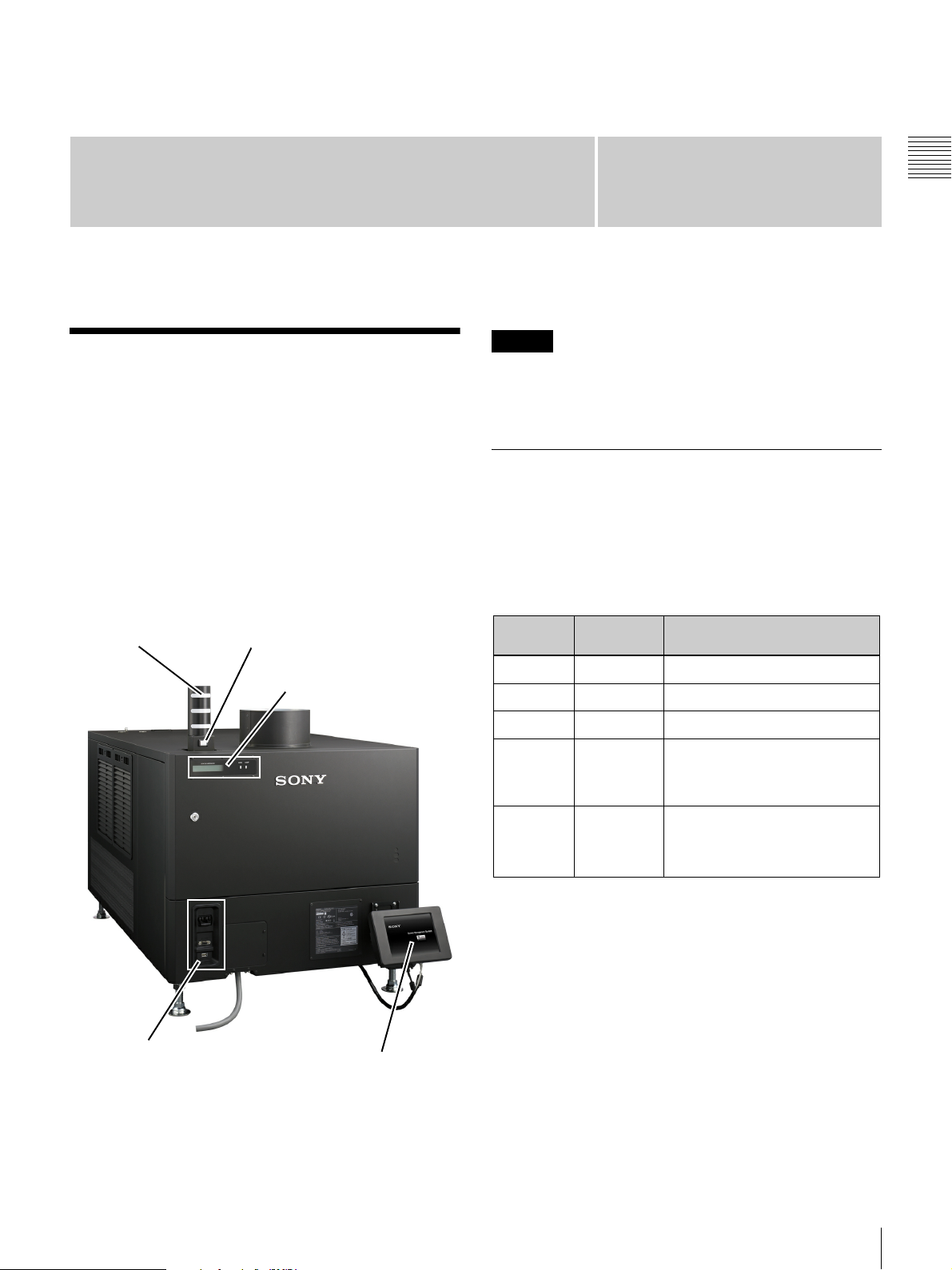
This document is a convenient “How To” guide to
SRX-R320 projector based Auditorium Unit operation
including Status Indicator information, and executing
specific functions via the Projectionist Terminal. The
location of the Projectionist Terminal, the Status Indicator
Lamps, Projector Status Message Display and Projector
Circuit Breaker panel on the Digital Cinema Auditorium
Unit are shown below.
Sony Digital Cinema SRX-R320 System
Status Indicator
Lamps
Projector
Circuit Breakers
System Start
Switch
Status Message Display,
Projector Power, Lamp Status
Projectionist
Terminal
Chapter
Caution
The SMS (Screen Management System) is available as a
component of the SRX-R320 system and the SRX-R220
system. (It cannot be purchased separately.)
1
Status Indicator Lamp
The Status Indicator Lamp is an easily seen indication of
the status of the Auditorium Unit. A brief description of
the meanings of the Lamp Color and Lamp State (solid,
flashing) are found in the following table.
Status Indicator Lamp
Lamp
Color
OFF OFF
RED FLASHING
YELLOW FLASHING
GREEN ON Operation Normal, System Stable,
GREEN FLASHING Ingesting/Validating Digital
a.Power OFF - Power is removed from the system,
subsystems
b.Major Error - Media Block offline. Enclosure temperature error. Playback stops during Play While Ingest due
to insufficient buffering.
c.Minor Error - Fan off (Enclosure, Media Block), Temperature warning, UPS abnormal condition, UPS battery replacement necessary. Low buffering during Play While Ingest.
d.Projector Transition - Projector changing from
STANDBY mode to ON mode.
1
1.The Digital Cinema System consists of several
subsystems such as the Projector , Media Block, SMS,
Enclosure, UPS etc.
Lamp State Meaning
Power OFF/System Shutdown
Major Error
Minor Error
Projector ON,
Projector STANDBY, Projector
Lamp OFF
Cinema Package (DCP),
Show Playing, Power ON/OFF
Sequence, or Projector Transition
1
are shutdown, UPS power is unavailable.
b
c
a
d
Chapter 1 User Guide
Overview
7
Page 8
Emergency Alert
Playlist Elements
The SMS features the ability to recognize an external
Emergency Alert signal and take one or more of the actions
enabled on the EMERGENCY OPERATIONS screen in
Chapter 1 User Guide
the SMS Controller application. Actions available in
response to an Emergency Alert signal are:
• Stop Current Show
• Disable Playback
• Lamp Douse
•Lamp OFF
• Audio Muting
• System Shutdown
Refer to the SMS Controller User’s Guide for additional
information relating to the Emergency Alert handling
capabilities of the system.
Note
The availability of the Emergency Alert feature is set
during system installation and configuration.
When the System
Shutdown option has not
been enabled, the receipt of
an Emergency Alert causes
the alert message
illustrated to the right to
appear. Once the
Emergency Alert has been
cleared, tap OK and the message closes. If the Emergency
Alert has not been cleared the message will close but will
reappear some seconds later.
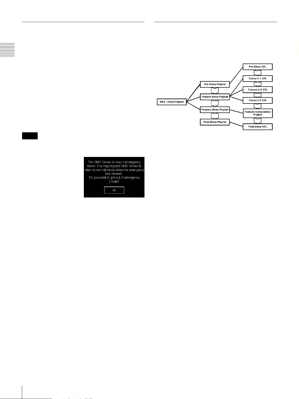
The hierarchy of a Show Playlist is intended to allow
inclusion of either Content (CPL), other Sub-Playlist(s) or
Commands. The structure of a typical Show Playlist is
shown in the illustration below.
Composition Playlist (CPL)
Composition Playlists (CPL) are shown on the right in the
above illustration and are the reference files required to
play the content.
CPLs exist on the lowest level of the Show Playlist (SPL)
hierarchy, and consist of the component files (e.g., video,
audio, subtitles) required for content playback.
Show Playlist (SPL)
As shown above, Show Playlists (SPL) are show lists that
consist of one or more CPLs with specified commands.
Multiple SPLs (containing CPLs and commands) can be
added as Sub-Playlists to a single additional layer of the
hierarchy.
8
Commands
Commands are Playlist Elements which are either
Automation Controls, i.e. external device triggers, (dim
house lights, open curtain, etc.) or Auditorium Unit control
events such as, Media Block Audio Control functions
(Muting) or Projector Control functions (Douser).
Commands or Functions may be designated as 3D type and
when these are included in a Playlist the SPL is identified
as a 3D Playlist even though no 3D Content is included.
Overview
Page 9
Play While Ingest (PWI)
Sony Trusted Circle
Play While Ingest (PWI) is an ingest method that allows
playback of a single CPL while it is ingesting. Unlike
Local Ingest and Network Ingest, PWI allows you to start
a presentation before the CPL ingest completes.
The following are precautions for Play While Ingest.
Available for CPLs only
Play While Ingest can only be performed on CPLs. If a
DCP contains multiple CPLs, the DCP will not be
recognized as a complete DCP until all the CPLs are
ingested. If a DCP is not recognized as complete, it cannot
be ingested to other LMT using S2S. (Playback is possible
even if a DCP is not recognized as a complete DCP.)
If a DCP contains subtitles or other overlays, or if a CPL
requires validation, Play While Ingest cannot be
performed.
You can also set intermissions for a CPL for which PWI is
performed or include the CPL in an SPL.
CPLs that are 30 minutes or longer in duration are
recommended
If you perform Play While Ingest on a CPL with a short
duration, playback may not start before ingesting is
complete due to an insufficient amount of buffering.
Sufficient network bandwidth (approx. 50 Mbps)
required
If sufficient ingest speeds cannot be obtained due to the
status of the library server or network and the buffer length
(playable duration) drops to below 7 minutes, an alert will
appear in the log. If the buffer length drops below
30 seconds, playback will stop. If playback stops, it cannot
be started again until the buffer length reaches 10 minutes
(under default settings) or more.
The buffer length is an approximate guide, and the actual
playable duration may differ slightly.
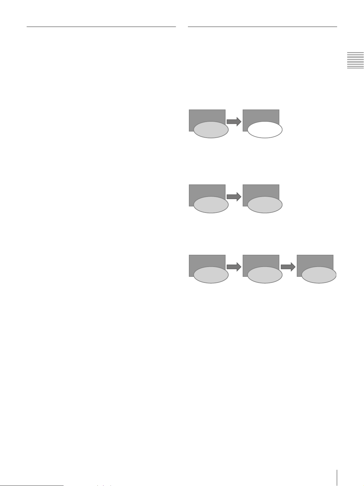
Sony Trusted Circle is a system that allows a DCP that has
been validated in one SMS to retain its validated status
after it is ingested to an SMS of any screen within the
cinema complex. This eliminates the additional time
required for validation in cinema complexes with multiple
screens.
Previous system
LMT A LMT B
S2S Ingest
DCP
(validated)
DCP
(not validated)
When S2S ingestion of a DCP was performed from LMT
A to LMT B in previous systems, validation was
required to present on LMT B.
Sony Trusted Circle
LMT A LMT B
S2S Ingest
DCP
(validated)
DCP
(validated)
When S2S ingestion of a DCP is performed from LMT A
to LMT B with Sony Trusted Circle, validation
information is ingested at the same time, allowing
immediate presentation on LMT B.
LMT A LMT B LMT C
S2S Ingest S2S Ingest
DCP
(validated)
DCP
(validated)
DCP
(validated)
The system also applies to S2S ingestion from LMT B to
LMT C, allowing immediate presentation.
Chapter 1 User Guide
Overview
9
Page 10
Login
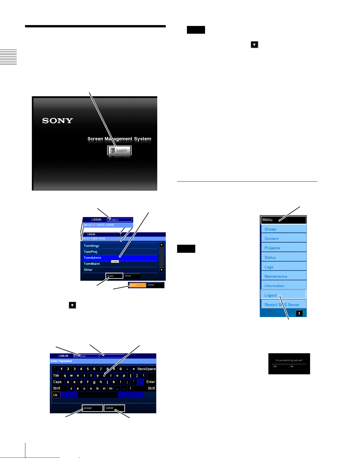
Access to control functions for the Screen Management
Chapter 1 User Guide
System requires the projectionist to login to the system.
Your Login ID and Password must be previously assigned
using the SMS Controller application.
Tap Login
Note
Trusted User Names
1
do not appear in the User Name
list. Tap the Scroll Down until “Other” can be
seen, tap Other and then tap Accept. An on-screen
keyboard will appear. Using the keyboard, enter your
User Name, tap Accept, enter your Password, and
then tap Accept.
3
Using the on-screen keyboard, tap your Password and
then tap Accept.
If you make an error in entering your Password, tap
Backspace to remove the last character. As you enter
your Password it is masked and appears above the
keyboard.
To abort the Login process, tap Cancel. The Login
process is cancelled and the display returns to the
Login screen.
The Now Showing screen appears when the Login process
is successful.
Logout
1
Tap Login on
the Projectionist
Selected User
Tap User Name
Terminal.
The LOG IN
screen appears
containing the
SELECT USER
NAME list.
2
If your User
Name is not
visible in the
SELECT USER
Tap Accept
NAME list, tap
Scroll Down until it can be seen. Tap your User
Name.
The selected User Name appears adjacent to LOG-IN,
then tap Accept. The Enter Password screen appears.
User Name
Masked P/W
Tap Password
Once you have Logged In to
Tap M e nu
the Projectionist Terminal, it
remains active and available to
user input. To close terminal
access, tap Menu and then tap
Logout.
Note
The illustration to the right
shows only the Level 1 menu.
However, instead of a single
level menu, you will see a two
level cascaded menu
appropriate to the screen
currently displayed on the
Projectionist Terminal.
After you tap Logout, the Menu
is closed and a popup
Tap Logout
confirmation message appears
(shown below and to the right). Tap Yes to complete the
Logout process.
The Login screen appears.
10
Login
1.A “Trusted User” is a user that has access to functions
dealing with Projector Maintenance operations, with
CancelAccept
Network Setup, and Auditorium Unit Security.
Page 11
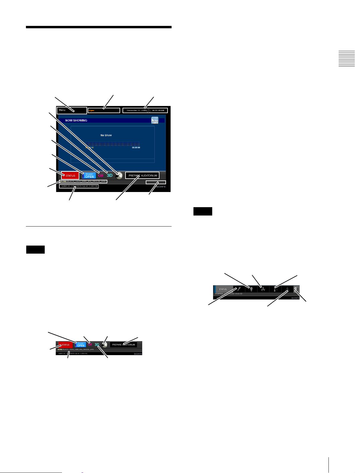
Basic Screen View
The Projectionist Terminal Screen is comprised of two
areas, a “Base Screen” or View and the “information” pane
where all menu selected functions and information
appears.
Tap f or Menus
Lamp
indicator
3D
indicator
Ghostbuster
Indicator
DOUSER
Control
STATUS
Alert
Current
Presentation
Version
Base Screen
Note
The Base Screen or “View” or Frame (illustrated above)
appears on all operational Projectionist Terminal screens
The Base Screen area includes a Menu button, the Douser
Control button, the Current User information, and a Date
& Time area along the top of the screen.
Current User
Prepare
Auditorium
Date & Time
Media Block
Status
• Ghostbuster Indicator
The Ghostbuster Indicator indicates whether the user
license has been obtained for the Ghostbuster function,
and whether the function is enabled.
When the production type is 3D and a Ghostbuster
license has been obtained, GB appears. Depending on
whether the Ghostbuster function is enabled or
disabled (deactivated), GB is displayed in pink or gray
respectively.
• Lamp ON/OFF indicator
The Lamp ON/OFF indicator provides an easily
viewed indication of the state of the Projector Lamp.
• Prepare Auditorium (Button)
The Prepare Auditorium button is a control which
sets the Projector to ON (from STANDBY or Lamp
OFF), opens the douser, and enables audio output from
the Media Block.
• STATUS Alert (Button)
The STATUS Alert button at the bottom of the screen
toggles the Status Warning/Selector buttons. These are
dual purpose Warning indicators and Selector buttons
which, when illuminated, display a warning related to
the status of the specific hardware sub system.
Note
The Status Alert button appears RED whenever any of
the Status Selector buttons are RED.
Tap the STATUS Alert button to view the Status
Warning/Selectors as shown below. Tap any of the
Status Selector buttons to view the specific Status
1
.
pane. Tap X to close the Status Selector buttons.
Lamp
Fans
Chapter 1 User Guide
Temperature
At the bottom of the Base screen is the Status alert/button,
the Douser Control button, the Lamp ON/OFF indicator,
and the Prepare Auditorium button.
DOUSER
Control
STATUS
Alert
Ghostbuster
Indicator
Status of Currently
Playing Title
Lamp ON/OFF
Indicator
3D Indicator
Prepare
Auditorium
• 3D Indicator (Projection Type)
The 3D Indicator provides an easily viewed
indication when the Auditorium Unit has been set for
stereoscopic presentation.
1.Installer screens and selected Maintenance screens have
functions specific to the task and do not allow for
accessing general operations.
Component
Information
Messages
• DOUSER Control (Button)
Controls Douser open/close.
Exit
Status
Basic Screen View
11
Page 12
Douse the projector light (DOUSER)
The DOUSER Control function on the PROJECTOR
CONTROL screen operates like a douser on a film
projector that blocks the light path.
When DOUSER is set to CLOSE, the screen in the
auditorium will be dark. However, the DOUSER function
Chapter 1 User Guide
affects only the image.
The sound will not be blocked. To turn off the sound as
well, you must use the AUDIO MUTING button.
Set DOUSER to CLOSE (closed)
The DOUSER control is a toggle button with status
indication.
The current status is shown by the status label
(OPEN/CLOSE) and the status indicator. When the status
indicator of the control is out (the label is OPEN), the
DOUSER is open and the image is shown on the screen in
the auditorium.
To darken the projector output (turn the DOUSER to
close), tap the DOUSER OPEN/CLOSE button in the
DOUSER block. A confirmation dialog appears. When
you tap Yes, the projector output is blocked and the screen
in the auditorium goes dark.
The label of the control button changes to CLOSE, and the
status indicator of the button lights up. The lamp of the
projector remains on.
Set DOUSER to OPEN (open)
The projector DOUSER control is a toggle button
(OPEN/CLOSE) with status indication.
The current status of the function control button is shown
by the status label (OPEN/CLOSE) and the status
indicator.
When the indicator is lit (label is CLOSE), the projector
DOUSER is closed and the screen in the auditorium is
dark.
To re-enable the projector output (turn the DOUSER to
open), tap the DOUSER OPEN/CLOSE button in the
DOUSER block. A confirmation dialog appears. When
you tap Yes, the projector output returns to normal, and the
screen in the auditorium shows the image. The label of the
control button changes to OPEN, and the status indicator
of the button goes out.
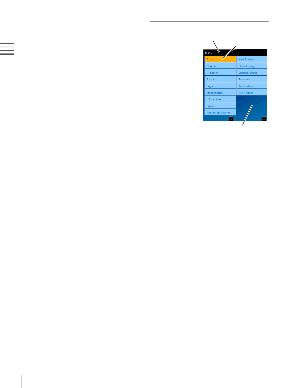
Menus
The Menu structure on
Projectionist Terminal
is two levels deep and
is illustrated to the
right. Some selections
may not appear as they
are Role dependant.
Tap Menu and the
Level 1 menu appears
providing access to
major operational
areas;
• Shows
•Content
• Projector
• Status
•Logs
• Maintenance
• Information
Note that when selecting the Menu both Level 1 and
Level 2 menus open showing the history of the most recent
selection. (The Level 2 menu will not appear on the initial
selection of Menu by the user.)
Tap the Level 1 selection and the level 2 menu changes to
provide access to those screens related to the level 1
selection and included functions, e.g., Now Showing,
Show Listing Manage Shows, etc.
In addition, from the Level 1 menu you have access to the
Logout and Restart SMS Server
Tap Men u
Level 2 Menu
1
functions.
Tap Level 1
Selection
12
1.A menu based System Shutdown is optionally available
based on system configuration.
Basic Screen View
Page 13
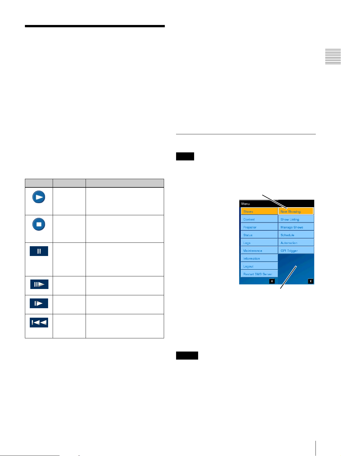
Shows
The Shows menu selection allows you to access the
information and control functions for the following areas.
• Now Showing
•Show Listing
• Manage Shows
• Schedule
• Automation
• GPI Trigger
To access Shows menus, tap Menu and then tap Shows.
The level 2 Shows Menu appears.
The Schedule selection opens the SCHEDULE pane
which allows you to view a list of the “shows” scheduled
for presentation during the displayed day. Each Show is a
distinct item with a specific Start Time and End Time. The
creation of Daily Schedules is realized using the SMS
Controller application.
Selecting Automation opens the AUTOMATION pane
which contains control buttons for each Automation
control configured in the connected Auditorium Unit.
When you select GPI Trigger, the GPI TRIGGERS pane
appears. The GPI TRIGGERS pane lets you register
various SPLs to be played when a particular GPI signal is
received.
Chapter 1 User Guide
The Now Showing selection opens an information screen
(Now Showing) for the current presentation. The primary
control available on Now Showing is the PLAY/STOP
control. An information area providing details of the
current presentation is present. Controls available on the
Now Showing screen are described in the following table.
Icon State Description
PLAY
Initiates presentation of the
Show (Now Showing) from
the Current Position. Available
only when STOPPED.
STOP
Halts presentation of the
current Show and the screen
goes dark. Available when
PLAYING or PAUSED.
PAUS E
Halts presentation of the
current Show with the last
frame of the content remaining
on screen. Available when
PLAYING.
FRAME
ADVANCE
RESUME Causes the current presentation to
RESTART Causes the current presentation to
Advances the current position of the
Presentation a single Frame.
Available only when PAUSED.
resume from the current frame.
Available only when PAUSED.
restart at the beginning. Available
only when the current presentation
has been STOPPED.
The Show Listing selection opens the SHOW LISTING
pane which displays information and controls relating to
Show Playlists (SPL) resident in the SMS.
Selecting Manage Shows opens the MANAGE SHOWS
pane where you can view brief details of any of the listed
SPL, create a New Playlist, and Edit or Delete a selected
SPL.
Now Showing
Note
Now Showing is the initial screen which appears following
a successful Login. Now Showing displays the status of the
Current Presentation (Show).
To view the status of the
current presentation, tap
Menu, tap Shows and
then tap Now Showing.
The NOW SHOWING
pane appears.
The primary
Presentation Control
available on Now
Showing is the
PLAY/STOP control.
Secondary controls may
be available based on
the current mode of the
presentation.
The central portion of
the Now Showing pane provides a quick summary of the
status of the current Show and the content being presented.
Show related information are; the Show Title, the Show
Current Position, and the Running Time/Remaining Time
(tap to switch view). Additionally, information about the
content (Content Title) is displayed when appropriate.
Caution
Subtitles may not appear for a few seconds immediately
after a presentation starts. Similarly, subtitles may not
appear for a few seconds at the start of offset playback or
immediately after a transition between a show and an
intermission.
Tap Now Showing
Shows Menu
Shows
13
Page 14
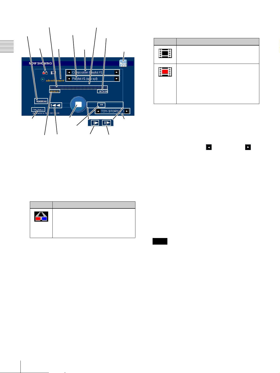
Progress Bar
Play Indicator
3D
Indicator
Chapter 1 User Guide
Play While
Ingest
Status
Current
Position
Content Title
Content
Type
PLAY/STOP
PAU S E
RESTART
• Progress Bar
The Progress Bar provides a graphic representation of
the progress of the presentation.
• 3D Indicator (Stereoscopic Glasses)
The 3D Indicator is present whenever the current
presentation contains 3D content. In this case, content
may be either actual 3D presentation Content or Show
Functions or Controls that are defined as 3D related.
Icon Description
Shown when the SPL contains 3D
(stereoscopic) content or includes a 3D
Function. This is also present when the
Title is a 3D CPL (Content) or linked to
a 3D Function.
• Content Title
The Name or Title of the currently playing Content
when the Show Title is a Show Playlist. When a SubPlaylist is present its Title will appear here instead of
the Content.
Content Titles may be lengthy and exceed the space
allocated. To view the complete Content Title, tap the
Title name. A popup message appears containing the
complete Content Title. Tap OK to remove the
message box.
• Content Type
Indicates the type of the currently playing Content,
e.g., Feature, Trailer, etc.
Warning Message
Running/
Remaining Time
Show
Title
RESUME
Schedule/
Manual Mode
Play While
Ingest Title
FRAME
ADVANCE
•Show Title
Displays the Title of the top level, i.e., the “show”,
currently playing and a status icon.
Icon Description
Normal - Shown when the SPL is ready
or during the time when presentation is
normal.
Error - Shown when an error is
experienced during presentation, e.g.,
MB reports the CPL video/audio track
to have a “FATAL” error, i.e., one
example is if the video is badly encoded.
Note: The Media Block must play the
content before the error is detected.
The Show Title is assigned using the SMS Controller
during the process of building the Show Playlist. The
Show Title is the “reference” for the consolidation of
the various Content, Sub-Playlists, and Commands
included in the named Show.
Show Titles may be lengthy and exceed the allocated
space. Tap the Scroll Left or Scroll Right
arrow (when available) to view the complete Title.
• Warning Message
An alert message appears in this area if the Content
awaiting presentation is not playable.
• Running/Remaining Time
An alternate display indicating either the Remaining
Time or the Total Running Time for the current
presentation. (Tap to change.)
• Play Indicator
This indicates whether the current presentation has
been started manually (MANUAL), as a scheduled
SMS event (SCHEDULE), or by an external trigger
input (AUTOMATION).
Note
Regardless of how the current presentation has been
started, once the presentation is stopped and restarted
using the PLAY/STOP control the Play Indicator
displays MANUAL.
• Current Position
Indicates the current position of the presentation.
When the Show is running this displays the elapsed
running time. When the Show is stopped the Current
Position indicates the point in the presentation where
presentation will resume when you tap PLAY.
• PLAY/STOP button
An alternate action (PLAY/STOP) screen “button”
which indicates what action (STOP is shown) will
occurs when it is tapped.
14
Shows
Page 15
• RESUME button
The RESUME button (shown on the inset) is only
available when the presentation is in PAUSE. The
RESUME button causes the current presentation to
begin playing from the current frame.
• RESTART button
The RESTART button is available when the current
presentation has been STOPPED. Normal action when a
presentation is stopped is to RESUME on PLAY from
the presentation’s current position.The RESTART button
allows you to begin presentation from the beginning of
the Show. A confirmation message appears.
• Play While Ingest Title
Displays the title of the CPL for which Play While
Ingest is being performed.
If the complete title of the content is not displayed, tap
the Scroll Left or Scroll Right arrow (when
available) to view the complete title.
Caution
You cannot play a CPL for which Play While Ingest is
in progress from the Now Showing pane. To start
playback, go to the Content Listing pane. For details,
see “Content Listing” on page 30.
Chapter 1 User Guide
• PAUSE button
The PAUSE button (shown) halts presentation of the
current Show with the last frame of the content
remaining on screen. Available when PLAYING.
When PAUSE is tapped the FRAME ADVANCE and
RESUME buttons become available.
• FRAME ADVANCE button
The FRAME ADVANCE button (shown on the inset)
allows you
Presentation by a single Frame. Available only when PAUSED.
to adjust (step) the current position of the
• Schedule / Manual mode button
In Schedule mode, the scheduled SPL is played
automatically. In Manual mode, the SPL will also be
played automatically when the end of the Wait time (as
set in the ini file) is reached.
• Play While Ingest Status
Displays the status of the Play While Ingest operation
currently in progress, and indicates the current
playability status of the CPL.
Display Description
Preparing Preparing to perform Play While Ingest.
Available
to Start
Buffer
length
Note
Playback is not possible.
The approximate wait time before playback
can be started is displayed. Playback is not
possible.
Buffering is in progress and the approximate
playable duration is displayed. Playback can be
started.
If the remaining time for the buffer length
drops to 30 seconds or below after playback is
started and the amount of buffering reaches
critically low levels, the display will turn red
and playback will stop.
If playback stops, buffering resumes and the
PLAY button will be disabled until playback is
possible.
When Play While Ingest is fully complete, the Play
While Ingest status display will disappear from the
Now Showing screen.
Note
When Play While Ingest is fully complete, the Play
While Ingest title display will disappear from the Now
Showing screen.
Show Controls
The basic PLAY/STOP Show Controls appear on the Now
Showing pane. With the exception of the Show Title and
Content Title scroll buttons, all controls on the Now
Showing pane are current mode dependant. For example,
when the Show is in the Play mode the only control
available to the projectionist is STOP.
STOP Presentation
To terminate presentation of the Current Show,
tap the STOP button (shown to the right) on the
Now Showing pane. Show presentation halts
and the screen goes dark
of the presentation is retained and a subsequent
execution of PLAY will resume the presentation from the
current position in the Show timeline.
STOP processing requires nominally about 3 seconds
before the presentation on the screen ends.
Caution
If a presentation is stopped during the showing of the SPL
for the intermission, the presentation cannot be resumed by
specifying an offset timecode.
START Presentation
When the Show is in the Stop mode, the PLAY control is
available to the projectionist. In addition, the RESTART
control will be available if a presentation is stopped while
in progress.
To initiate presentation of the indicated
Show (Now Showing) from the Current
Position, tap the PLAY button.
PLAY processing requires about 6 seconds
(nominally) before the presentation appears
on the screen.
1.While the Douser does NOT close the output of the
Media Block is muted.
1
. The current position
Shows
15
Page 16

Note
Executing PLAY begins presentation of the Show from
the current position indicted in the Now Showing pane. To
begin presentation of the Show from its beginning, tap
RESTART. A confirmation message appears and then tap
Chapter 1 User Guide
YES.
RESTART Presentation
When STOP has been executed while a
presentation is in progress the RESTART
button appears. RESTART is used to begin
the presentation from the Start of the Show. RESTART
only appears when a presentation is stopped while in
progress. To begin the presentation from the Start of Show,
tap RESTART. A confirmation message appears. Tap
YES and presentation of the Show begins.
Resume presentation from a specified position
When you stop a presentation that is in progress, the Offset
button appears. If you tap the Offset button, the ENTER
REWIND TIME dialog box for specifying the resume
position appears. The position at which the presentation
was stopped after the start of the content playback is
indicated by Base Offset timecode.
To specify the offset timecode at which to resume
presentation, tap the hh (hour), mm (minute), and ss
(second) boxes, and use the Plus and Minus
buttons to enter a value for each box separately. You can
also use the Rewind Time drop-down menu to select a
specific amount of time to rewind from the Base Offset.
When you tap the Accept button, the presentation will
resume from the specified position.
PAUSE Presentation
When the current show is in progress the
PAUSE control is available. The PAUSE
function halts the current presentation but
leaves the most recent frame image presented on the
screen. To pause presentation of the current Show, tap
PAUSE.
Caution
After pausing a presentation in a system for which AV
DELAY is set, wait at least 1 second before resuming
playback.
FRAME ADVANCE
When the current show has been PAUSED
the FRAME ADVANCE control is
available. FRAME ADVANCE allows you
to “adjust” which frame of the current presentation appears
on the auditorium screen.
RESUME Presentation
When the presentation has been PAUSED
the RESUME button appears. RESUME
allows you to start the presentation from the
current position.
Show Listing
The SHOW LISTING pane displays information and
controls relating to Show Playlists (SPL) resident in the
SMS. Brief details of any of the listed SPL are available.
To view the available
Show Playlists, tap
Menu, tap Shows and
then tap Show Listing.
The SHOW LISTING
pane (illustrated below)
appears.
Tap Show Listing
Caution
Offset playback is only possible in the minus direction
during PWI presentations.
16
Shows
The primary control
available on Show
Listing is the
PLAY/STOP control. In
addition, a Details
button is available that
opens a popup
containing detailed
information about the
selected Playlist.
Shows Menu
Page 17
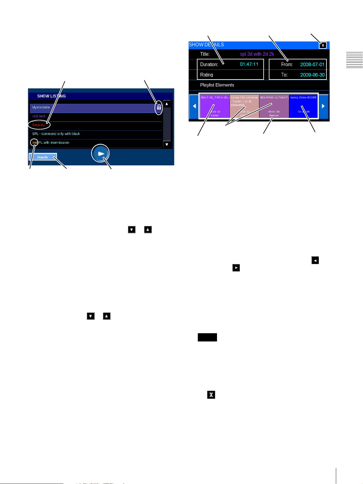
The central portion of the Show Listing pane can scroll
through the list of all Show Playlists (SPL) available for
presentation. A SPL that includes content that is not
playable because a KDM is not available is indicated with
a padlock as illustrated. Any SPL that is missing content is
shown in red.
Content Missing
Intermission
SPL
Details
Not Playable - KDM
PLAY/STOP
Play Show
A Show Playlist which is available for presentation (not
“Locked”) may be played from the SHOW LISTING pane.
To play a specific Show, locate the Title in the list. If the
Title of interest is not visible, tap either or to scroll
the list until the specific Title is found. Once the Title has
been located, tap to select the Show Title and then tap
PLAY. The Show presentation begins.
View Show Details
A Show Playlist (SPL) can be comprised of one or more
CPL, other Sub-Playlist, command actions of Automation
Controls that are internal to the Auditorium Unit. To view
the content detail information
the Title in the SHOW LISTING list. If the Title of interest
is not visible, tap either or to scroll the schedule list
until the specific Title is found. Once the Title has been
located, tap to select the Show Title and then tap Details.
The SHOW DETAILS pane appears.
1
for a specific Show, locate
Show Information
Content
3D Content
Valid Use Dates
Playlist
Elements
Sub-Playlist, tap for
Details
Close
The SHOW DETAILS pane contains three major areas.
They are: the Show Information, its Valid Use Dates and,
a sequence of Playlist Elements which can be scrolled.
Each “Show” or “Title” in the SHOW LISTING pane is
comprised of one or more individual Playlist Elements.
These elements may be Composition Playlists (Content) or
Sub-Playlists
2
. The sequence of presentation of the
Playlist Elements is displayed in a SHOW DETAILS pane.
•Show Information
The Show Information group contains basic
information regarding the Show. This includes the
Title, Duration, and MPAA Rating.
Show Titles may be lengthy and exceed the allocated
space. Tap (when available) the Scroll Left or
Scroll Right arrow to view the complete Title.
• Valid Use Dates
A KDM is required to play a CPL comprising
encrypted content elements. The date range during
which the KDM is valid is shown here. These dates are
validated on a periodic basis and are subject to change
even after the Content Elements have been loaded into
the SMS.
Note
Valid Use Dates apply only to the auditorium
associated with the current Auditorium Unit. Other
systems in the same facility may have different Valid
Use Dates for the same Content Element(s).
Chapter 1 User Guide
1.Automation Controls, Auditorium Unit Commands and
presentation “Gaps” included in the Show Playlist do not
appear in Show Details. To view Automation Controls or
Auditorium Unit Commands contained in a Show Playlist
you must edit the Show Playlist (see “Edit Show Playlist
(SPL)” on page 24).
• Close Details
To close the Details screen for the Content Element,
tap (Close). This will return you to the previous
level of Show Details.
2.Automation Controls and Auditorium Unit Commands
do not appear in the Show Details popup. Scheduled
“Gapes” in the presentation also are not shown in Show
Details.
Shows
17
Page 18
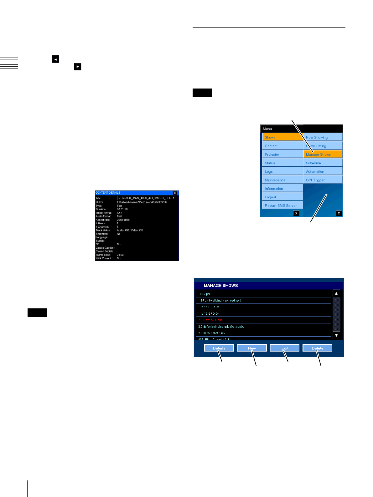
• Playlist Elements
The Playlist Elements group provides a sequenced,
graphic representation of the individual Content and
Sub-Playlists that comprise the Show. Tap the Scroll
Left arrow see elements earlier in the Show or
Chapter 1 User Guide
Scroll Right arrow to see elements later in the
Show.
While Playlist Elements may be either Content (CPL),
Automation Controls, Auditorium Unit Commands, a SubPlaylist, or presentation “Gaps” (black-leader) only
Content or Sub-Playlists are visible in the Show Details
view. To view the details of an included Sub-Playlist, tap
the target Sub-Playlist and a new Show Details popup
appears.
View Playlist Element Details
Each Show is comprised of one or more Playlist Elements
which may be either Content (CPL) or a Sub-Playlist. Each
Content element has its own characteristics, e.g., Audio
Format, Aspect Ratio, etc. A Sub-Playlist is simply a Show
Playlist containing its own Playlist Elements.
To view detail
information for an
included CPL, tap
the Content of
interest on Show
Details. The
CONTENT
DETAILS popup
appears containing
additional
information, e.g.,
Running time, Image format, Aspect ratio, etc. about the
selected Content. When the Playlist Element of interest is
a Sub-Playlist then a new SHOW DETAILS popup
appears.
Manage Shows
The MANAGE SHOWS pane displays information and
controls relating to Show Playlists (SPL) resident in the
SMS. From the MANAGE SHOWS pane you can create a
New SPL, Edit an existing SPL, view Details of an
existing SPL and Delete an existing SPL.
Note
Access to the Manage Show features is Role restricted.
To Manage Shows, tap
Menu, tap Shows and
then tap Manage
Shows. The MANAGE
SHOWS pane
(illustrated below)
appears.
The ability to Manage
Shows is a feature
available from the
Projectionist Terminal.
While the majority of
SPL creation, editing
and management will
normally take place
using the SMS
Controller, similar features have been added to the
Projectionist Terminal thus allowing operators to makes
changes when the need arises. The functions available on
the MANAGE SHOWS pane are shown in the illustration
(below). A brief description follows.
Tap Manage Shows
Shows Menu
Note
The Frame Rate and HFR Content have been added as the
last line.
18
Shows
Details
New
(SPL)
Edit
(SPL)
Delete
(SPL)
• Details - Allows you to view the Playlist Elements
included in the SPL in their sequence of execution.
• New - Allows you to create a new SPL using
available Content and a Sub-Playlist(s). In addition,
you can add Commands to the SPL.
• Edit - Allows you to make changes to an existing
SPL.
Page 19
• Delete - Allo ws you to remove an existing SPL from
the system. This does not remove the included
Content from the system.
View Playlist Details
Each “Show” or “Title” appearing in the MANAGE
SHOWS list is comprised of one or more individual
Playlist Elements. These elements may be Content (CPL)
or Sub-Playlists.
To view detail information for a specific Show, locate the
Title in the MANAGE SHOWS list, tap to select the Show
Title and then tap Details. The SHOW DETAILS pane
appears. The Playlist Elements comprising the Show are
displayed in the order of presentation in SHOW
DETAILS.
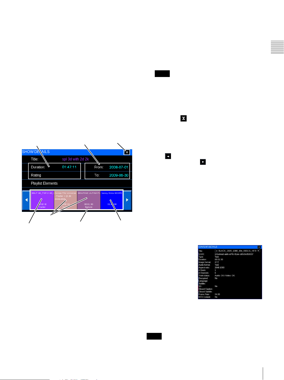
The SHOW DETAILS popup contains three major areas.
They are: the Show Information, its Valid Use Dates and,
a sequence of Playlist Elements
Show Information
Valid Use Dates
1
.
Close
• Valid Use Dates
A KDM is required to play a CPL comprising
encrypted content elements. The date range during
which the KDM is valid is shown here. The Valid Use
Dates group indicates the date range during which the
selected Show can be presented. These dates are
validated on a periodic basis and are subject to change
even after the Content has been loaded into the SMS.
Note
Valid Use Dates apply only to the auditorium
associated with the current Auditorium Unit. Other
systems in the same facility may have different Valid
Use Dates for the same Content (CPL).
• Close Details
To close the Show Details screen for the Playlist
Content, tap (Close). This will return you to the
previous level of Show Details.
• Playlist Elements
The Playlist Elements group provides a sequenced,
graphic representation of the individual Content and
Sub-Playlists that comprise the Show. Tap the Scroll
Left arrow to see Playlist Elements earlier in the
Show or Scroll Right arrow to view Playlist
Elements later in the Show.
Chapter 1 User Guide
Content
3D Content
Playlist
Elements
Sub-Playlist, tap for
Details
•Show Information
The Show Information group contains basic
information regarding the Show. This includes the
Title, Duration, and MPAA Rating.
Show Titles may be lengthy and exceed the space
available in the display. To view the complete Show
Title, tap the Title name. A popup message appears
containing the complete Show Title. Tap OK to
remove the message box.
1.Playlist Elements which are “Gaps” in presentation
(interstitial black-leader), Automation Controls or
Auditorium Unit Commands do not appear in the Playlist
Details view.
While Playlist Elements may be either Content (CPL),
Commands, or a Sub-Playlist, only Content or SubPlaylists are visible in the Show Details view. To view the
details of an included Sub-Playlist, tap the target Sub-
Playlist and a new Show Details popup appears.
View Playlist Element Details
Each Show is comprised of one or more Playlist Elements
which may be “Content” (CPL) or Sub-Playlists. Content
included in the SPL has its own characteristics, e.g., Audio
Format, Aspect Ratio, etc. Sub-Playlists include Content
with its own characteristics.
To view detail
information for
Content, tap the
Content of interest
on Show Details.
If the target Playlist
Element is Content,
CPL DETAILS
appears containing
additional
information, e.g.,
Image Format, Aspect ratio, etc. about the selected
element. If the target Playlist Element is a Sub-Playlist,
then a new SHOW DETAILS pane appears.
Note
The Frame Rate and HFR Content have been added as the
last line.
Shows
19
Page 20
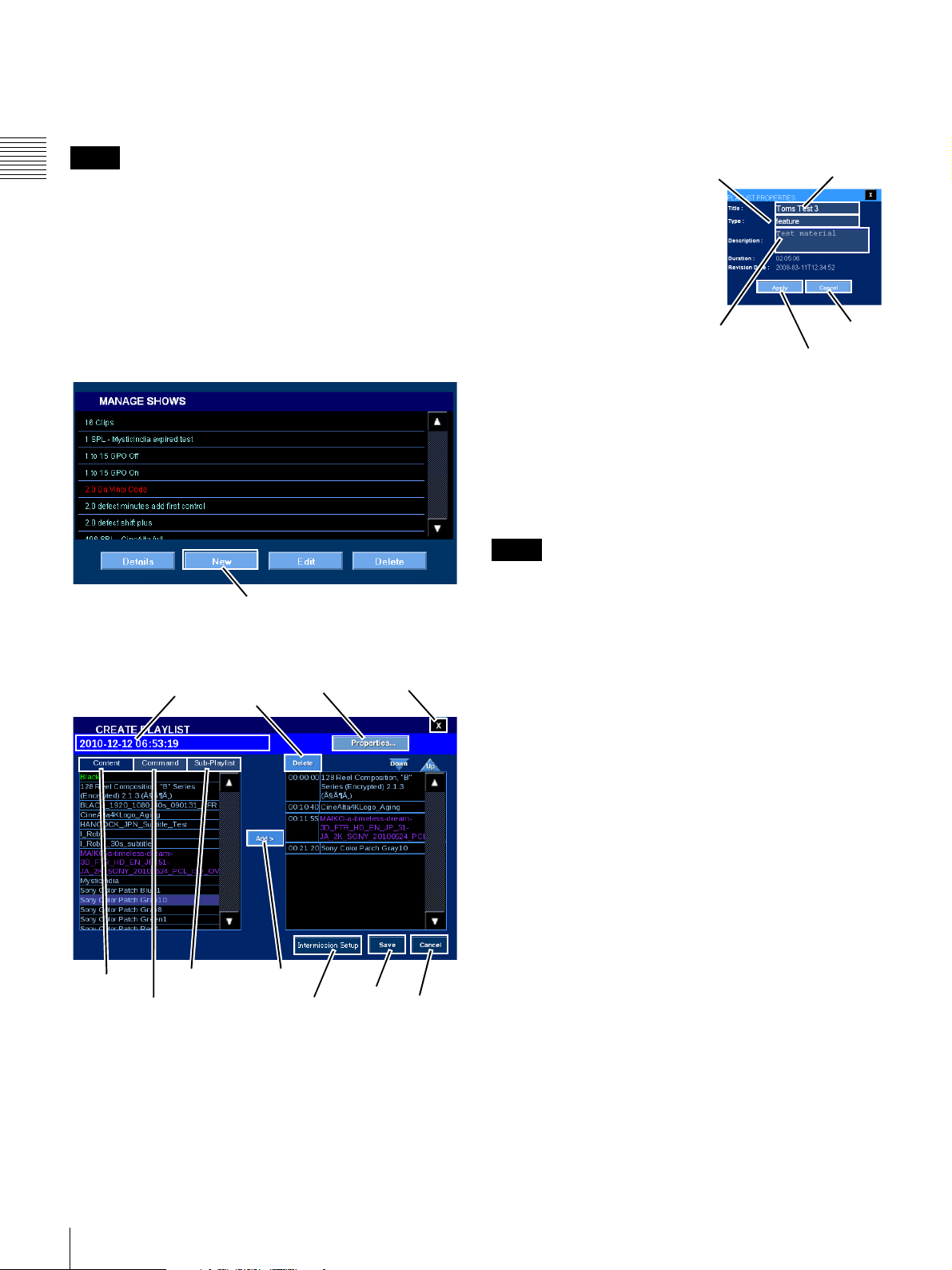
Create Show Playlist (SPL)
The ability to create New Show Playlists has been included
in MANAGE SHOWS
Note
Chapter 1 User Guide
Inclusion of 3D Content an SPL (as a sub-playlist) that
includes 3D Content, or a 3D associated Projector
FUNCTION sets the created Show Playlist to a 3D type
and requires that the Projection Type be set to Single 3D
for presentation
2
3D Show Playlist you cannot include a Projector
FUNCTION that is other than a 3D FUNCTION.
To create a New Playlist, tap Menu, tap Shows and then
tap Manage Shows. The MANAGE SHOWS pane
appears.
1
from the Projectionist Terminal.
. While 2D Content may be included in a
The default Title for a new SPL is the current Date/Time
(YYYY-MM-DD hh:mm:ss). The SPL Title can be
changed in Properties.
Set Playlist Properties
To set the Playlist
Type
Title
Properties, tap Properties.
The PLAYLIST
PROPERTIES popup
appears.
PLAYLIST PROPERTIES
contains descriptive
information about the SPL.
When you tap either Title
(limited to 64 characters)
or Description (limited to
Description
Cancel
Apply
512 characters), an onscreen keyboard appears. Tap to set the information and
then tap Enter to close the keyboard. To set the Playlist
Type, tap Type and then tap to make your selection from
the list.
Once information has been set in PLAYLIST
PROPERTIES, tap Apply and the popup will close.
New
To add a new Show Playlist, tap New. The CREATE
PLAYLIST popup appears.
Title
Content
1.Access to features under MANAGE SHOWS is Role
restricted.
2.See “Projection Type” on page 46.
Sub-Playlist
Commands
Delete
Properties Close
Add
Intermission
Setup
Save
Cancel
Note
Setting of the Projection Type, a manual operation, is
separate from setting the correct projector FUNCTION,
i.e., a FUNCTION that is identified as a 3D FUNCTION.
To insure that 3D content presentation is successful the
first Playlist Element in a 3D SPL should be a FUNCTION
appropriate to the 3D Projection Type.
Add Start Offset (Virtual Black Leader)
In film, black leader is used to provide a brief interval
between different content. This often is used simply to
provide pacing to the sequence of content being presented,
e.g., between trailers or between the last trailer and the
feature start.
In Digital Cinema, “black” can be either the absence of the
playback of any Content (virtual black
3
) during
presentation or it can be actual black content supplied as a
CPL included in the DCP. Virtual Black is realized by
creating a Start Offset for the following Content Element.
When creating a Start Offset, provision is made for
establishing a duration of the of the offset. When Black is
actual content, its duration is of a predetermined length and
the Content Type should be “transitional
3.The virtual Black Leader is created by electronically
muting the image output from the Content playback
subsystem (Media Block). The Start Offset (virtual Black
Playlist Element) appears green in the Content list and in
the subsequent Playlist.
4.Transitional Content is usually described as “extremely
short content (1 to 15 seconds) separating unrelated
compositions”.
4
”.
20
Shows
Page 21
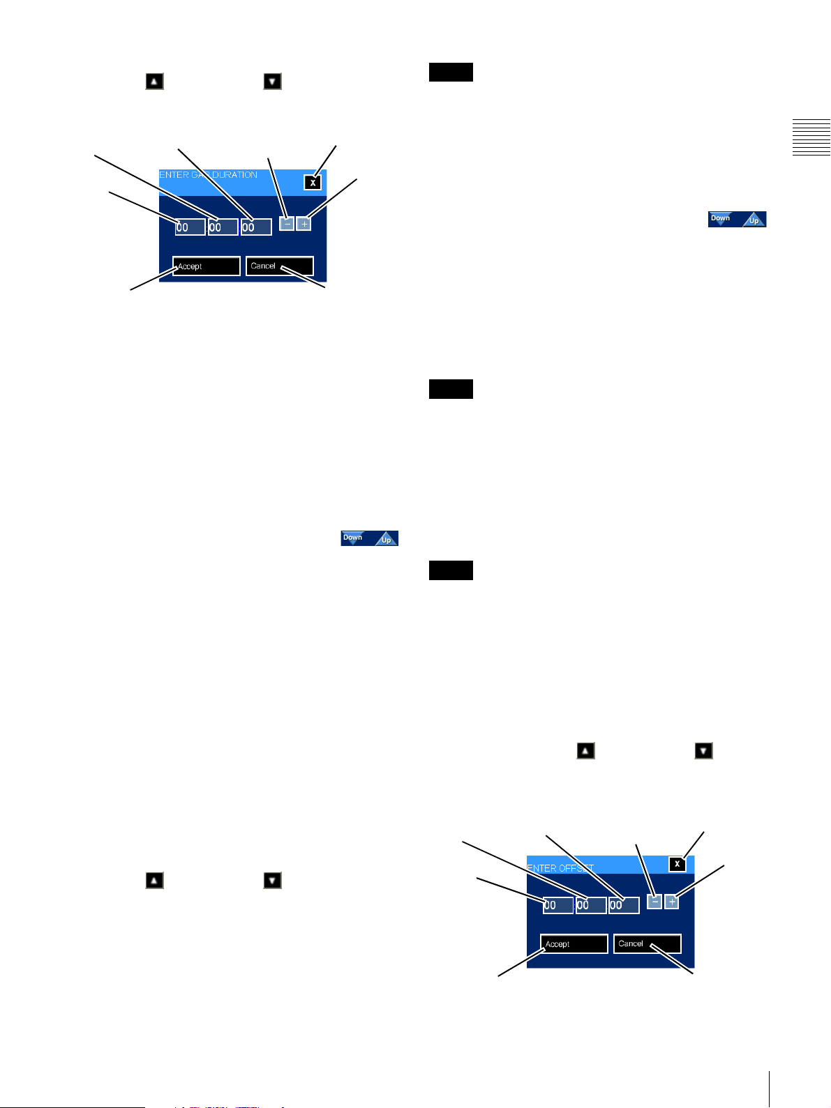
To add a Start Offset to the Playlist, tap Content, tap either
the Scroll Up or Scroll Down arrow until you
locate Black, tap Black to select, and then tap Add. The
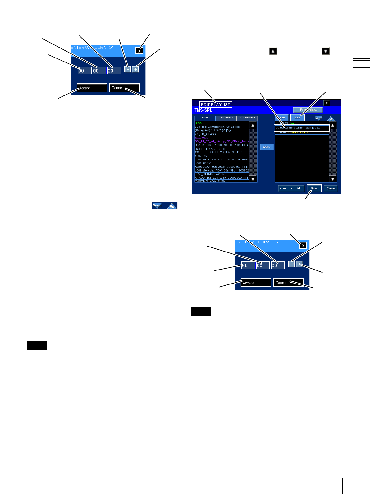
ENTER GAP DURATION popup appears.
Minutes
Hours
Accept
Seconds
Minus
Close
Plus
Cancel
Note
3D Content is identified in purple. When 3D Content is
added to an SPL the PLaylist Title is shown as purple in the
list of Playlists.
When Playlist Elements already exist you may need to
reposition the newly added Content to a different location
in the Playlist timeline.
To move the newly added Playlist Element, in
the Playlist tap the Title (select) and then tap
Down or Up (illustrated to the right) to move the selected
Playlist Element one event position in the desired
direction. Continue to tap Down or Up until the selected
Playlist Element is in the desired position in the Playlist.
Chapter 1 User Guide
The duration of the Start Offset (virtual Black Leader) is
set using the ENTER GAP DURATION popup. This
duration is an absolute value and adjusts the start time of
the following Playlist Element in relation to the end time
of the preceding Playlist Element. To enter a value, tap the
target, i.e., Hours, Minutes, or Seconds, and then tap (or
touch-and-hold) either the Plus or Minus to
increment/decrement the value of the selected target.
When the desired value is reached, tap Accept. The
ENTER GAP DURATION popup closes and the added
Black appears in the right-hand list at the end of existing
Playlist Elements.
Position the Start Offset to the correct position
within the existing Playlist Elements. To
move the Start Offset (Black Playlist Element), in the right
side list tap the Black to select and then tap Down or Up
(control illustrated to the right) to move the Start Offset
one event position in the desired direction. Continue to tap
Down or Up until the Start Offset is in the desired position
in the Playlist. The start time of following Playlist
Elements are delayed to accommodate the duration of the
Start Offset.
To add Black which is actual Content, locate the Content
and add it to the Playlist in the same manner as you would
add other Content. (See “Add Content” on page 21.)
When all changes are complete, tap Save. CREATE
PLAYLIST closes and you are returned to the MANAGE
SHOWS pane.
Add Content
To add Content to the New Playlist, tap Content (left-side
list) to display available Composition Playlists. Tap either
the Scroll Up or Scroll Down arrow until you
locate the Content of interest, tap the Content Title to
select, and then tap Add. The added Content appears as a
Playlist Element at the end of the Playlist.
When all changes are complete, tap Save. CREATE
PLAYLIST closes and you are returned to the MANAGE
SHOWS pane.
Note
Be sure to tap Save before leaving this screen. If you close
the screen without tapping Save, all changes will be lost.
Add Command
Playlist Command Elements can be identified as a 3D
related Command at the time they are created and are
indicated by a “[3D]” designation shown in purple. This
“3D” designation is retained when the Command Element
appears in the Playlist.
Note
If a 3D Command Element is added to a Playlist the
Playlist is identified as a 3D playlist and appears in purple.
Command timing is related to the absolute time of
execution from the beginning of the Show Playlist. During
the process of adding a Command, an Offset popup will
open where you can set the appropriate value. To add
Command(s) to the current Playlist, tap Command to
display the available Automation Controls, e.g., curtain,
lights, etc., and Auditorium Unit Commands, e.g., Douser.
Tap either the Scroll Up or Scroll Down arrow
until you locate the Command of interest, tap the
Command to select, and then tap Add. The ENTER
OFFSET popup appears.
Minutes
Hours
Seconds
Minus
Close
Plus
Accept
Cancel
Shows
21
Page 22
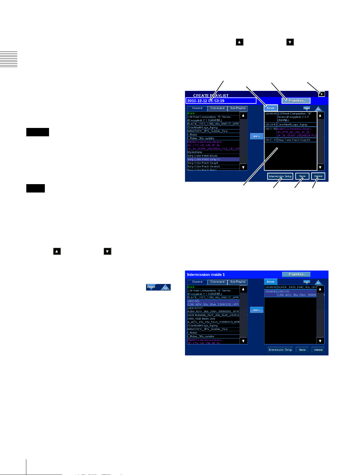
The offset of the added Command is the absolute offset
from the beginning of the Playlist and is set using the
ENTER OFFSET popup. To enter a value, tap the target,
i.e., Hours, Minutes, or Seconds, and then tap (or
touch-and-hold) either the Plus or Minus to increment the
value of the selected target. When the desired value is
Chapter 1 User Guide
reached, tap Accept. The ENTER OFFSET popup closes
and the added Command appear as a Playlist Element
identified by its yellow color. The Offset value is displayed
in the first column.
When all changes are complete, tap Save. CREATE
PLAYLIST closes and you are returned to the MANAGE
SHOWS pane.
Caution
When executing a projector control command from an
SPL, wait at least 50 seconds after the projector lamp turns
on before executing the command. The command may be
ignored if you execute the command before 50 seconds.
Add Sub-Playlist
1
Delete Playlist Element
To delete a Playlist Element from the new Playlist, tap
either the Scroll Up or Scroll Down arrow (right
side list) until you locate the Playlist Element of interest,
tap the Playlist Element to select, and then tap Delete. The
Playlist is removed from the displayed list.
Title
Delete
Properties
Close
Note
Previously created Show Playlists are available as a SubPlaylist only if they do not contain a Sub-Playlist. If they
contain 3D (Stereoscopic) Content they appear in purple.
When an included Sub-Playlist is identified as a 3D
Playlist
2
then the including Playlist will also be identified
as a 3D Playlist.
To add a Sub-Playlist, tap Sub-Playlist. Tap either the
Scroll Up or Scroll Down arrow until you locate
the Playlist of interest, tap the target Sub-Playlist to select,
and then tap Add. The Sub-Playlist appears as the Playlist
Element at the end of the Playlist.
When Playlist Elements are existing you may
need to reposition the newly added SubPlaylist to a different position within the existing events.
To move the Sub-Playlist, in the right side list tap the Title
to select and then tap Down or Up (control illustrated to
the right) to move the selected Playlist Element one event
position in the desired direction. Continue to tap Down or
Up until the selected Playlist Element is in the desired
position in the Playlist.
When all changes are complete, tap Save. CREATE
PLAYLIST closes and you are returned to the MANAGE
SHOWS pane.
Playlist Elements
Intermission
Setup
Save Cancel
When all changes are complete, tap Save. CREATE
PLAYLIST closes and you are returned to the MANAGE
SHOWS pane.
Intermission Setup
An intermission can be scheduled for a Composition
Playlist registered in a Show Playlist. Select the content
(CPL) in the Playlist, and tap the Intermission Setup
button. The Setup Intermission pane appears.
22
1.An existing Playlist will only appear as a Sub-Playlist if
it does not include a Playlist. The SPL may contain only
one nested Sub-Playlist level.
2.A playlist may be identified as a 3D Playlist even if it
does not actually contain 3D Content. This occurs if the
included Playlist includes a 3D Function or Command.
Shows
Page 23
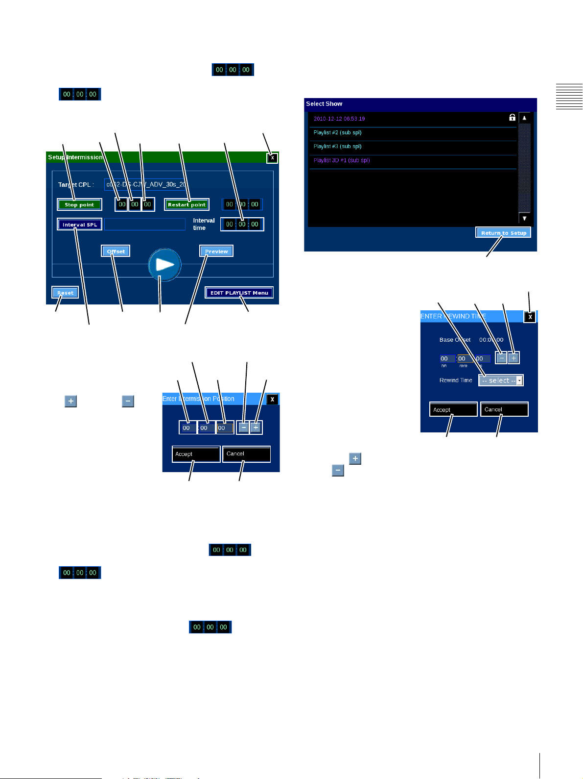
To specify the Intermission location, set the target CPL to
the Play condition and tap the Stop point button at the point
where the Intermission should start. The
indication at the side shows the timecode. You can also
tap besides the Stop point button to bring up the
Enter Intermission Position popup window.
You can specify a Playlist (SPL) to be played during the
interval period. This is the Interval SPL. When you tap the
Interval SPL button, the Select Show pane appears. Tap
the desired SPL and then tap Return to Setup.
Chapter 1 User Guide
Stop
point
Restart EDIT PLAYLISLT
Interval SPL
To enter a value, tap the
target, i.e., Hours, Minutes,
or Seconds, and then tap
Minutes
Hours
Seconds
Offset Play
Restart
point
Preview
Minutes
Hours
Interval
time
Menu
Close
Minus
PlusSeconds
(or touch-and-hold) either
Plus or Minus
button to increment the
value of the selected target.
When the desired value is
reached, tap Accept.
The Enter Intermission
Position popup window
closes. The Intermission
Accept Cancel
Position value is shown in
the Stop point field.
To specify the Restart point, set the target CPL to the Play
condition and tap the Restart point button at the point
where the Intermission should end. The
indication at the side shows the timecode. You can also
tap besides the Restart point button to bring up
the Enter Intermission Position popup window. Specify
the restart setting using the same method as described for
the Stop point.
Return to Setup
To specify an offset, tap the
Offset button. The ENTER
Rewind
Time
Close
PlusMinus
REWIND TIME pane
appears.
The additional command
lets you specify an absolute
offset time from the start of
the Playlist. This is done
using the ENTER OFFSET
popup window. To enter a
value, tap the target, i.e.,
Hours, Minutes, or
Seconds, and then tap (or
touch-and-hold)
Accept Cancel
either Plus or
Minus button to increment the value of the selected
target. When the desired value is reached, tap Accept. The
ENTER OFFSET popup window closes.
To check the operation of Contents (CPL) with
Intermission, tap the Preview button. The Preview
playback starts a few seconds before the start of the
Intermission (Stop point) and continues for a few seconds
past the end of the Intermission (Restart point). The
Interval CPL is played during the Intermission period.
When the setting is complete, tap the EDIT PLAYLIST
Menu button to return to the CREATE PLAYLIST pane.
To specify an interval duration, tap to the right
of Interval Time. The Enter Interval Duration popup
window appears. Specify the interval setting using the
same method as described for the Stop point.
Shows
23
Page 24

Edit Show Playlist (SPL)
Playlist editing operations are usually carried out from the
SMS Controller application. However, editing existing
Show Playlists can also be realized from the Projectionist
Terminal.
Chapter 1 User Guide
Note
Access to features under MANAGE SHOWS is Role
restricted.
To Edit an existing Playlist, tap Menu, tap Shows, tap
Manage Shows. The MANAGE SHOWS pane appears.
Edit
Tap either Scroll Up or Scroll Down until you
locate the Title of interest. Tap the Title to select and then
tap Edit. The EDIT PLAYLIST popup appears.
Title
Delete
Properties Close
View/Edit Playlist Properties
To view or edit the
Playlist Properties, tap
Properties. The
Title
Playlist Properties
popup appears.
Typ e
Playlist Properties
contains descriptive
information about the
SPL. When you tap
either Title (limited to
Description
Cancel
Apply
64 characters) or
Description (limited
to 512 characters), an on-screen keyboard appears. Tap
keys to set the information and then tap Enter to close the
keyboard. To set the Playlist Type, tap Type and then tap
to make your selection from the list.
Once information has been set in the Playlist Properties,
tap Apply and Playlist Properties will close. You must tap
Save on the EDIT PLAYLIST pane to apply changes.
Add Black (Leader)
Black (Leader) is used to provide a brief interval between
different content. This often is used simply to provide
pacing to the sequence of content being presented, e.g.,
between trailers or between the last trailer and the feature
start.
In Digital Cinema, “black” can be either the absence of the
playback of any Content (virtual black
1
) during
presentation or it can be actual black content supplied as a
CPL included in the DCP. In the former case where a
virtual black interval is manufactured during the
presentation process, provision is made for establishing a
duration of the Black interval. When Black is actual
content, its duration is of a predetermined length and the
Content Type is “transitional
2
”.
24
Content
Commands
Shows
Sub-Playlist
To add Virtual Black to the Playlist, tap Content, tap
either the Scroll Up or Scroll Down arrow until
you locate Black (appears as green in the list), tap Black
to select, and then tap Add. The ENTER GAP
DURATION popup appears.
Add
Save Cancel
Intermission
Setup
1.Virtual Black is created by electronically muting the
image output from the Content playback subsystem
(Media Block). A Virtual Black Playlist Element appears
green in the Content list and in the subsequent Playlist.
2.Transitional Content is usually described as “extremely
short content (1 to 15 seconds) separating unrelated
compositions”.
Page 25
Minutes
Hours
Seconds
Minus
Close
Plus
Adjust Black (Leader) Duration
The duration of Virtual Black
1
can be adjusted to meet
timing needs. To adjust the duration of Black/Leader in the
SPL, tap either the Scroll Up or Scroll Down
arrow until you locate the target Black (appears as green in
the Playlist), tap the Black element to select (the Edit
button appears) and then tap Edit.
Chapter 1 User Guide
Accept
Cancel
The duration of the added Black (Leader) is set using the
ENTER GAP DURATION popup. This duration is an
absolute value and adjusts the start time of the following
Playlist Element in relation to the end time of the
proceeding Playlist Element. To enter a value, tap the
target, i.e., Hours, Minutes, or Seconds, and then tap (or
touch-and-hold) either the Plus or Minus to increment the
value of the selected target. When the desired value is
reached, tap Accept. The ENTER GAP DURATION
popup closes and the added Black appears in the righthand list at the end of existing Playlist Elements.
Position the added Black to the correct
position within the existing Playlist Elements.
To move the Black Playlist Element, in the right side list
tap the Black to select and then tap Down or Up (control
illustrated to the right) to move the Black Playlist Element
one event position in the desired direction. Continue to tap
Down or Up until the Black Playlist Element is in the
desired position in the Playlist. The start time of existing
Playlist Elements are adjusted to accommodate the
duration of the Black Playlist Element.
To add Black which is actual Content then locate the
Content and add it to the Playlist in the same manner as
you would add other Content. (See “Add Content” on page
21.)
When all changes are complete, tap Save. CREATE
PLAYLIST closes and you are returned to the MANAGE
SHOWS pane.
Edit Playlist
Tap Black Element
Edit
Save
The Enter Gap Duration popup appears, adjust the
Duration value, tap Accept and then tap Save.
Seconds
Minutes
Hours
Accept
Note
Close
Minus
Plus
Cancel
Be sure to tap Save before leaving this screen. If you close
the screen without tapping Save, all changes will be lost.
Note
Be sure to tap Save before leaving this screen. If you close
the screen without tapping Save, all changes will be lost.
1.Only the duration of Manufactured Black can be
adjusted.
Shows
25
Page 26
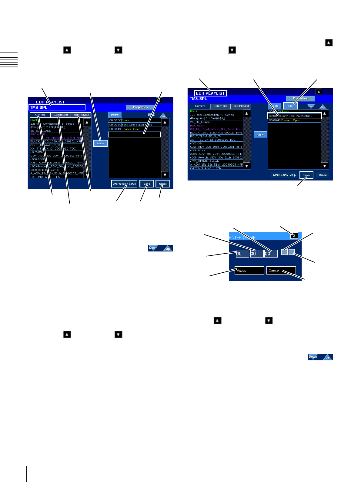
Add Content
To add Content to the current Playlist, tap Content to
display available Composition Playlists (CPL). Tap either
the Scroll Up or Scroll Down arrow until you
locate the Content of interest, tap the Content Title to
select, and then tap Add. The added Content appears as a
Chapter 1 User Guide
Playlist Element at the end of the Playlist.
Title
Content
Add
Sub-Playlist
Commands
Intermission
Setup
New Playlist Element
Added Here
Save
The Time value shown in the left-most column is the time
when the Content will be presented based on its offset from
the start point (00:00:00) of the Playlist.
Cancel
Move Playlist Command
Playlist Commands can be moved within the SPL. To
move a Command in the SPL, tap either the Scroll Up
or Scroll Down arrow until you locate the target
Command, tap the Command event to select (the Edit
button appears) and then tap Edit.
Edit Playlist
Tap C o m m a nd
Edit
Save
The Enter Offset popup appears, adjust the Offset value,
tap Accept and then tap Save. Edit Playlist closes and you
are returned to the MANAGE SHOWS pane.
Seconds
Minutes
Close
Minus
To move the newly added Playlist Element,
tap the Title to select and then tap Down or
Up (illustrated to the right) to move the selected Playlist
Element one event position in the desired direction.
Continue to tap Down or Up until the selected Playlist
Element is in the desired position in the Playlist.
When all changes are complete, tap
Save
. Edit Playlist
1
closes and you are returned to the MANAGE SHOWS pane.
Add Command
To add Command(s) to the current Playlist, tap Command
to display the available Automation Controls. Tap either
the Scroll Up or Scroll Down arrow until you
locate the Command of interest, tap the Command to
select, and then tap Add. The added Command appears as
a Playlist Element at the end of the Playlist.
When all changes are complete, tap
Save
. Edit Playlist
closes and you are returned to the MANAGE SHOWS pane.
1.When Commands are included in the Playlist you may
have to Save the Playlist and then reopen it to obtain a
view that represents the actual sequence of Playlist
Element presentation.
Hours
Plus
Accept
Add Sub-Playlist
2
Cancel
To add an existing Playlist as a Sub-Playlist, tap
Sub-Playlist to display existing Playlists. Tap either the
Scroll Up or Scroll Down arrow until you locate
the Sub-Playlist of interest, tap the Sub-Playlist to select,
and then tap Add. The Sub-Playlist appears as the Playlist
Element at the end of the Playlist.
To move the Sub-Playlist, in the right side list
(Playlist Elements) tap the Title to select and
then tap Down or Up (control illustrated to the right) to
move the element one event position in the desired
direction. Continue to tap Down or Up until the selected
Playlist Element is in the desired position in the Playlist.
2.An existing Playlist will only appear as a Sub-Playlist if
it does NOT include a Playlist. When creating a Show
Playlist, only one nested Sub-Playlist level is allowed.
26
Shows
Page 27
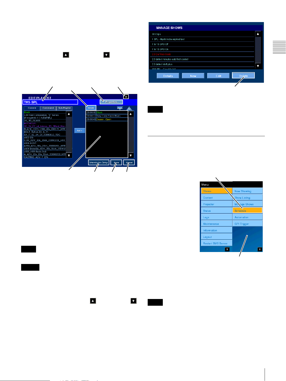
When all changes are complete, tap Save. Edit Playlist
closes and you are returned to the MANAGE SHOWS
pane.
Delete Playlist Element
To delete a Playlist Element from an existing Playlist, tap
either the Scroll Up or Scroll Down arrow (right
side list) until you locate the Playlist Element of interest,
tap the Playlist Element to select, and then tap Delete. The
Playlist is removed from the displayed list.
Chapter 1 User Guide
Title
Delete
Playlist Elements
Properties
Intermission
Setup
Close
Save Cancel
When all changes are complete, tap Save. Edit Playlist
closes and you are returned to the MANAGE SHOWS
pane.
Delete Show Playlist (SPL)
Playlist management operations are usually carried out
from the SMS Controller application. However, the ability
to delete existing Show Playlists from the Projectionist
Terminal is also available.
Note
Access to features under Manage Shows is Role restricted.
Caution
Currently no confirmation message appears when you
Delete a Playlist.
To delete an existing Playlist, tap Menu, tap Shows, and
then tap Manage Shows. The MANAGE SHOWS pane
appears. Tap either the Scroll Up or Scroll Down
arrow until you locate the Playlist of interest, tap the
Playlist to select, and then tap Delete.
Delete
The selected Playlist is removed from the system.
Note
Deleting a Show Playlist does not delete the Content,
Commands, or other Sub-Playlists from the system.
Schedule
Schedules (Show Schedules) which have been created
using the SMS Controller are viewable from the
Projectionist Terminal.
To View and Manage
Schedules, tap Menu,
tap Shows and then tap
Schedule. The
SCHEDULE pane
appears and, by default,
presents a list of shows
scheduled for
presentation on the
current date. To view
schedules for other dates
tap Previous Day/Next
Day. Information in the
SCHEDULE pane
includes the (Show)
Title and the Start
Time/End Time for each
Show.
Schedules are based on a single day view and, using the
Projectionist Terminal, you can “scroll” to view schedules
available for the currently selected day.
Note
If the Title of interest is not visible, verify that you are
viewing the correct schedule date and, if necessary, scroll
the schedule list until the specific Title is found.
Tap Schedule
Shows Menu
Shows
27
Page 28
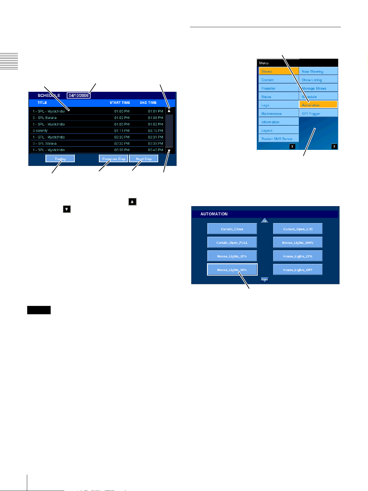
The SCHEDULE pane indicates the date of the displayed
schedule at the top-center. Each Show presented during the
day appears in the SCHEDULE list as a distinct item with
a specific Start Time and End Time. Because of the limited
amount of display space, it will likely be necessary to
scroll to see the complete schedule for any specific day.
Chapter 1 User Guide
Show Titles
Go To To day
Schedule Date
Previous
Day
Next
Day
To scroll the screen to see additional Show Schedules for
the indicated day, tap either Scroll Up or
Scroll Down on the SCHEDULE pane.
Scroll
Up
Scroll
Down
Automation
From the SMS
Controller you can
create Automation
“control” events linked
to external controls for
legacy auditorium
devices. Automation
controls can be executed
from the Projectionist
Terminal.
To View and execute
Automation controls,
tap Menu, tap Shows
and then tap
Automation. The
AUTOMATION pane
appears and contains a set of labelled “buttons” which can
be used to trigger the external device.
To execute the Automation control, tap the labelled
Button.
Tap Automation
Shows Menu
View Previous Day/Next Day
When the SCHEDULE pane appears, it displays Shows
scheduled for presentation on the current day. When you
wish to view schedules for another day tap either Previous
Day or Next Day in the lower portion of the pane.
View Today
To return to viewing the Schedule for today, tap Today in
the lower portion of the SCHEDULE pane.
Caution
As preparations for presenting each CPL can take several
seconds, the duration of presentations may be longer than
normally expected if several CPLs exist in the Show
Playlist. As a result, some presentations may not be
finished by the time the next presentation is scheduled to
begin. In such cases, the next presentation will not begin.
Automation Control
The control label and the electrical characteristics of the
signal output by the SMS System must be established
using the SMS Controller. Refer to the SMS Controller
User’s Guide for additional information.
In software version 2.30 and later, Z-axis auto-adjustment
and calibration functions for projectors can be executed as
Automation Controls.
The Z-axis auto-adjustment control is called
“PjCmd_AutoZAxisAdj”, and the calibration control is
called “PjCmd_Calibration”. These two Automation
Controls cannot be deleted.
The Z-axis auto-adjustment and calibration cannot be
executed using the Automation Control buttons. They are
added to SPLs for execution. For details about SPL
samples, consult your local Sony representative.
To make Z axis adjustments, tap Lamp Install in the
Projector menu.
28
Shows
Page 29
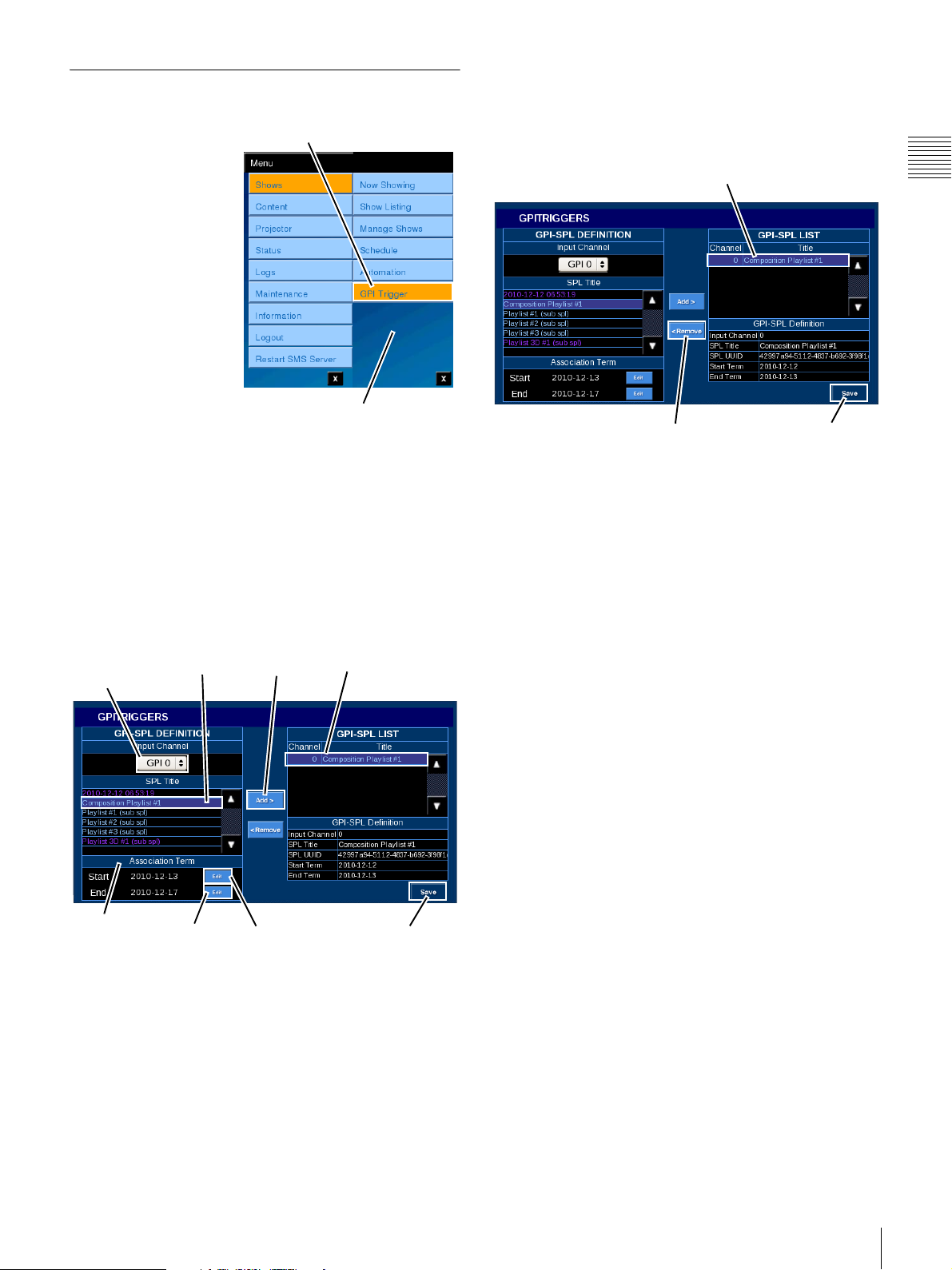
GPI Trigger
The GPITRIGGERS
pane shows all Playlists
(SPL) for which
playback will be
controlled by using an
external GPI signal as a
trigger.
In the GPITRIGGERS
pane, you can register
and cancel GPI
triggered SPL playback.
To bring up the
GPITRIGGERS pane,
tap Manu, Shows, GPI
Trigger in sequence.
Adding an SPL to the GPI-SPL List
SPLs that will be played using GPI triggering are shown in
the GPI-SPL list. To register an SPL in the GPI-SPL list,
first select the GPIO input channel, and then select the SPL
to play by GPI triggering from the SPL Title list. The
period during which GPI triggering is active can be set
with the Association Term item. Tap the Edit button and
specify the Start and End points. After using the Add
button to register the entry in the GPI-SPL LIST, tap the
Save button to save the setting.
Tap G P I Tr igger
Shows Menu
Deleting an SPL from the GPI-SPL list
To delete an SPL registered in the GPI-SPL list, select the
SPL and tap the Remove button.
Then tap the Save button to save the setting.
GPI-SPL List
Remove Save
Chapter 1 User Guide
GPIO input
channel
Association
Team
SPL Title Add GPI-SPL LIST
Edit Edit
Save
The GPIO Profile setting for the respective GPIO input
channel can be made at the SMS Controller. This should be
completed before setting the GPI Trigger. For information
on the steps for making GPIO Channel and GPIO Profile
settings, refer to the SMS Controller User’s Guide.
Shows
29
Page 30
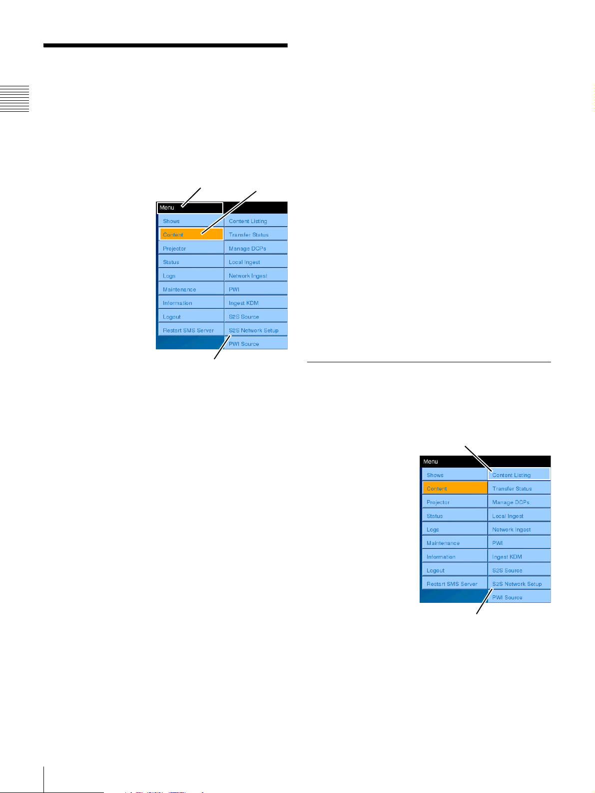
Content
When referring to Content we are talking about the
Chapter 1 User Guide
Composition Playlist. A CPL is comprised of the actual
track files, each of a single essence type (e.g., sound,
image, subtitles), and references required to play these
files. The CPL is always at the base level of a Show
Playlist hierarchy.
The Content menu
selection
1
allows you to
access the information
and control functions for
the following areas.
•Content Listing
• Transfer Status
• Manage DCPs
• Local Ingest
• Network Ingest
•PWI (Play While
Ingest)
•Ingest KDM
•S2S Source
• S2S Network Setup
•PWI (Play While
Ingest) Source
Tap M e nu
Pop-up Menu
Tap Content
The Network Ingest selection opens the NETWORK
INGEST pane for ingesting a DCP via the network. Source
addresses can be added via S2S Source.
The PWI menu selection opens the PLAY WHILE
INGEST pane which allows you to control ingest of a CPL
from an external library server via the network. The source
address can be added with the PWI Source menu selection.
The Ingest KDM menu selection opens the INGEST KDM
pane which displays a list of predefined folders where
KDMs may be found. These folders are defined using the
SMS Controller. Each folder can contain more than one
KDM. The controls available on the INGEST KDM pane
are Details and the Ingest control.
The S2S Source selection opens the S2S SOURCE pane,
which shows a list of source addresses that can be used to
perform Ingest via the network.
The S2S Network Setup selection opens the S2S
NETWORK SETUP pane, which shows S2S address
allocation information.
The PWI Source menu selection opens the PWI SOURCE
pane which displays the address, login name, and
password assignments for the library server.
Content Listing
To access Content menus, tap Menu and then tap Content.
The Content Menus appear.
The Content Listing menu selection opens the Content List
which contains a list of all CPL present in the system. The
primary control available on the Content List pane is the
PLAY/STOP control and the Details button.
The Transfer Status menu selection opens the TRANSFER
STATUS pane which displays information and controls
relating to the progress of DCP being ingested into the
Media Block controlled storage. Available controls are;
Details, Remove Job, Cancel Job, Pause Jobs.
The Manage DCP menu selection opens the MANAGE
DCP pane where you can view Details of any of the listed
DCP, Delete an existing DCP, or Validate a previously
ingested DCP.
The Local Ingest menu selection opens the LOCAL
INGEST pane which displays a list of predefined folders
where DCPs may be found. These folders are defined
using the SMS Controller. Each folder can contain more
than one DCP. The only control available on the LOCAL
INGEST pane is the Ingest control. By repeating the Ingest
step, multiple DCPs may be ingested in succession.
1.Access to some menu selections are Role restricted.
The CONTENT LIST pane displays all Composition
Playlists (CPLs) resident in Media Block controlled
storage. Brief details of any of the listed CPL are available.
To view the resident
Tap Content Listing
Content/Composition
Playlists (CPL), tap
Menu, tap Content and
then tap Content
Listing. The CONTENT
LIST pane (illustrated
below) appears.
The primary control
available on Content
List is the PLAY/STOP
control. In addition, a
Details button is
available which opens a
popup containing
detailed information
Content Menu
about the selected Content.
The central portion of the Content List pane is a list of all
Composition Playlists (CPL) resident in Media Block
controlled storage. Any CPL which is not available for
presentation because the KDM is not available or invalid
is indicated with a padlock as illustrated. A CPL that is
incomplete is shown in red.
30
Content
Page 31
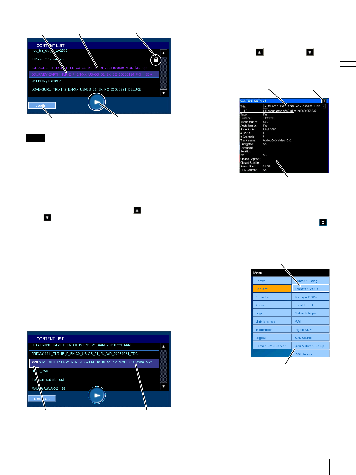
Selected
3D Content
Not Playable
View Content Details
To view detail information for a specific CPL, locate the
specific Content in the list. If the Title of interest is not
visible, tap either Scroll Up or Scroll Down until
the specific Title is found. Once the Title has been located,
tap to select the Content Title and then tap Details. The
CONTENT DETAILS pane appears.
Chapter 1 User Guide
Details
Note
PLAY/STOP
The CPL list may not always appear immediately after the
SMS starts up. In such cases, wait a few minutes, and then
try to display the CPL list screen again.
Play Content
Content which is available for presentation (not “Locked”)
may be played from the CONTENT LIST pane. To play a
specific CPL, locate the Content in the list. If the Title of
interest is not visible, tap either Scroll Up or Scroll
Down until the specific Title is found. Once the Title
has been located, tap to select the Content Title and then
tap PLAY. The Content presentation begins.
Playing Back Play While Ingest Content
Content for which Play While Ingest is being performed
will include “PWI” in front of their title in white text, and
the title itself will appear in red text. Buffing is being
performed for content displayed in red, and such content
cannot be played.
When buffering is complete, the content title will turn from
red to blue and playback will be possible. For details, refer
to the Play While Ingest status in the Now Showing screen.
Tap to select the Content Title and then tap PLAY. The
Content presentation begins.
“PWI” Included in Title
Playback Possible
when Title is Blue
The CONTENT
Content Title Close
DETAILS popup
contains selected
information about
the Content (CPL).
In addition to the
Content Title and its
identification
(UUID) Content
Details includes the
following; Content
Type, e.g., Feature,
Duration, Image
and Audio Formats,
Content Details
Aspect Ratio, # of
Reels, # Channels (Audio), Track Status, and if the CPL is
encrypted. Newly added Content Details are; Language,
Subtitle and 3D.
To close the CONTENT DETAILS popup, tap Close .
Transfer Status
A Digital Cinema
Package must be
ingested into the RAID
storage system under
control of the Media
Block prior to it being
available for
presentation.
Because an individual
ingest job can require
considerable time and
multiple ingest jobs may
be pending, the ability to
view the status of the
processes is available
from one of the Content
Menus. In addition, DCP queued for Ingest can now be
managed from the Projectionist Terminal. To view the
status of the DCP Ingest processes, tap Menu, tap Content
and then tap Transfer Status. The TRANSFER STATUS
pane appears.
Tap Transfer Status
Content Menu
Content
31
Page 32
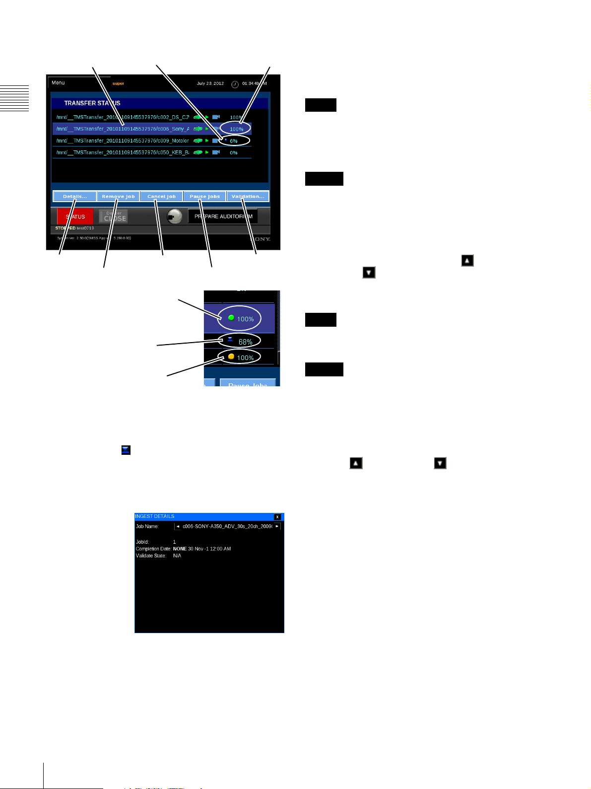
Selected
Ingesting
Complete &
Validated
Pause/Resume Jobs
An alternate action control which allows you to manually
Pause Jobs and Resume Jobs queued for DCP Ingest. A
confirmation message appears.
Chapter 1 User Guide
Note
Ingest jobs may be scheduled to run concurrently with
content playback, but playback will have priority, which
will cause the Ingest process to take longer than when
performed while playback is stopped.
Caution
After pausing a job, wait at least 30 seconds before
resuming the job.
Cancel Job
Allows you to Cancel the ingest of a job in progress. To
cancel the Ingest Job in progress, locate the target DCP in
Details
Remove Job
Cancel Job
Pause Jobs
Validation
the Ingest queue using the Scroll Up or
Scroll Down arrow, select the Job and then tap Cancel
Job. A confirmation message appears, tap Close. Once
Ingest Complete (100%)
and DCP Validated
cancelled, you must reschedule the Ingest of the DCP.
Note
Jobs queued for Ingest but not yet in progress must be
Ingest in progress
Ingest Completed (100%)
Verification in process
Removed from the job queue.
Caution
When canceling a Network Ingest operation, wait at least
3 minutes after the operation starts before canceling it.
From the TRANSFER STATUS pane you can view the
status of and manage selected ingest processes. During
ingest the percentage of completion is shown adjacent to
the ingesting icon . A solid green status indicates that
Ingest is complete (100%) and the DCP has been
Validated. A yellow status (flashing) indicates that
Validation is in progress.
View Ingest Job Details
To view Details of
the selected ingest
process, tap
Details. The
INGEST DETAILS
popup appears
containing
information about
the status of the
selected job. The
INGEST DETAILS
popup also indicates if the DCP Ingest job has completed
and whether the DCP was Validated. Tap the Close icon to
return to TRANSFER STATUS.
Remove Job
You can only remove Jobs that have completed or have
been cancelled. To remove the selected Ingest Job from the
queue, locate the target DCP in the Ingest queue using the
Scroll Up or Scroll Down arrow, select the Job
and then tap Remove Job. A confirmation message
appears, tap OK.
Set Automatic Validation
Tap Validation to open the settings dialog box.
Tapping ON enables automatic validation, and tapping
OFF disables it.
When automatic validation is enabled, Validation is
displayed in orange.
32
Content
Page 33
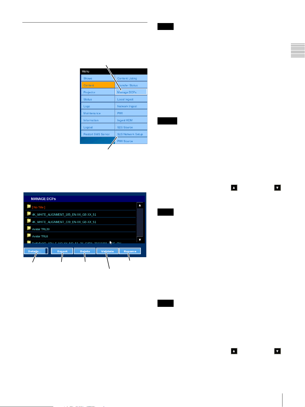
Manage DCPs
The MANAGE DCPs pane includes the ability to view the
Details of a selected DCP, to Delete a selected DCP, and
to check the Validate status of a selected DCP.
To Manage DCPs, tap
Menu, tap Content and
then tap Manage DCPs.
The MANAGE DCPs
pane appears.
While the majority of
DCP management will
take place using the SMS
Controller. However,
similar features have
been made available
from the Projectionist
Terminal to allow
operators to perform
DCP management tasks
when the need arises.
You can save up to 350 DCPs on the LMT.
The functions available on the MANAGE DCPs pane are
shown in the illustration (below). A brief description
follows.
Tap Manage DCPs
Content Menu
Note
If a DCP component (CPL) has been included in a Show
Playlist (SPL), any attempt to remove the DCP and a
confirmation message will appear. This is because deleting
the DCP while an SPL exists that uses a CPL associated
with the selected DCP would cause playback of the SPL to
fail. Once all SPLs in use have been deleted, then the DCP
can be deleted.
To remove an existing DCP, tap Menu, tap Content, and
then tap Manage DCPs. The MANAGE DCPs pane
appears. Tap the DCP to select, and then tap Delete.
A DCP can be deleted during a showing, but a DCP that is
included in a currently playing SPL cannot be deleted.
Caution
DCP ingestion cannot be performed while a DCP is being
deleted.
Validate DCP
The Validate DCP feature causes the Media Block to
validate the content of the DCP packing list and then
validate each file (essence) described in the packing list
against a check value present in the packing list for each
essence file. To validate a DCP, tap Menu, tap Content,
and then tap Manage DCPs. The MANAGE DCPs pane
appears. Tap either the Scroll Up or Scroll Down
arrow until you locate the DCP of interest, tap the DCP to
select, and then tap Validate.
Chapter 1 User Guide
Details
Export
Delete (DCP)
Rename (DCP)
Validate (DCP)
View DCP Details
Allows you to view details of the selected DCP. To view
information about an existing DCP, tap Menu, tap
Content, and then tap Manage DCPs. The MANAGE
DCPs pane appears. Tap the DCP to select, and then tap
Details.
Export DCP
Allows you to export a DCP from the Media Block
controlled storage. Tap the DCP to select, and then tap
Export, the target storage can be selected.
Delete DCP
Allows you to delete an existing DCP from the Media
Block controlled storage.
Note
The Validate process uses the same Media Block resources
as presentation and its duration is related to the Content
length. Content presentation will take priority, the Validate
process is suspended during presentation and resumes
when presentation is completed.
Rename DCP
Allows you to change the DCP Name. A DCP may or may
not be “named” during the creation of the distribution
package. If a name has been included in the distribution the
name may not be one that is easily recognized by the user.
The feature allows you to Rename the DCP for easier
reference.
Note
If a DCP is renamed and then subsequently ingested again
the assigned name will be lost and the DCP name will
revert to the name assigned (if any) when the distribution
package was created.
To rename an existing DCP, tap Menu, tap Content, and
then tap Manage DCPs. The MANAGE DCPs pane
appears. Tap either the Scroll Up or Scroll Down
arrow until you locate the DCP of interest, tap the DCP to
select, and then tap Rename
. An on-screen keyboard
Content
33
Page 34
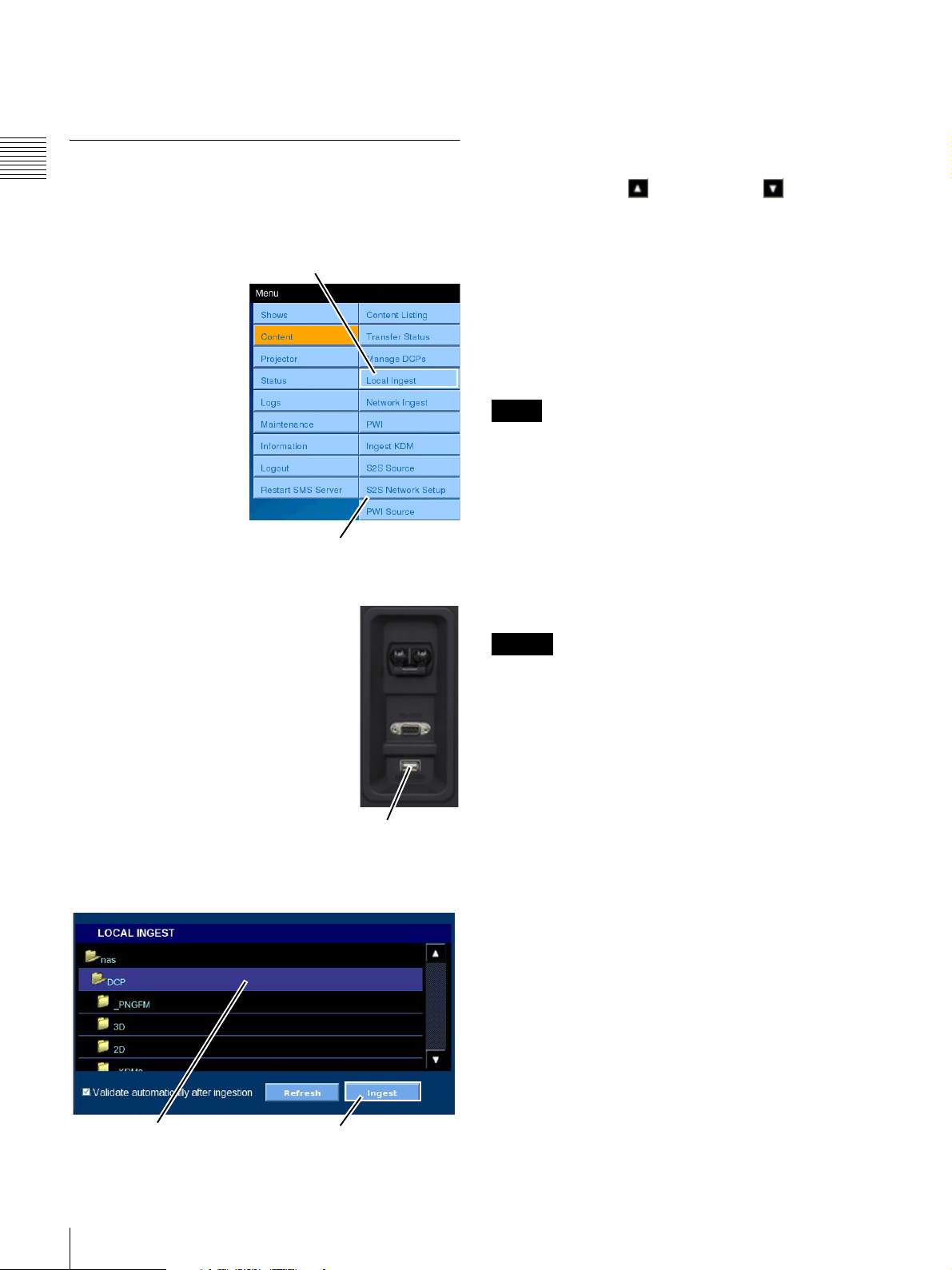
appears. Using the keyboard, enter the new DCP Name
and then tap ENTER.
Local Ingest
Chapter 1 User Guide
A Digital Cinema Package (DCP) must be ingested into
the Media Block’s RAID storage system. This process
occurs under control of the Media Block.
To Ingest one or more
DCPs, tap Menu, tap
Content and then tap
Local Ingest. The
LOCAL INGEST pane
appears.
The DCP Ingest feature
includes the ability to
start more than one DCP
ingest process. While the
majority of DCP
operations will take
place using the SMS
Controller, similar
features have been added
to allow operators to
perform DCP Ingest tasks when the need arises.
On the rear of the SRX-R320
projector, below the power switch and
RS-232C connector, there is a USB
port labeled INGESTPORT. You can
plug a USB 2.0 Drive into this
connector and it will appear as a folder
in the LOCAL INGEST list.
The only function available on the
INGEST DCP pane is Ingest (shown in
the illustration below). By placing a
check mark in the “Validate
automatically after ingestion” check
box, the validation step can be
performed immediately after ingestion (default is no
validation).
Tap Local Ingest
Content Menu
Ingest Port
Because a DCP commonly refers to a folder that comprises
a number of files, it is shown as a folder in the LOCAL
INGEST list. The target DCP is found in one of the folders
which have been defined using the SMS Controller based
on fixed locations where storage/transfer media can be
attached to the system or network. To located the target
DCP, tap Scroll Up or Scroll Down until you find
the desired top level folder and then tap the folder view its
contents. Again, Scroll Up or Scroll Down to locate the
target DCP, tap to select and then tap Ingest. The DCP
Ingest job is placed at the end of the Ingest queue for
processing. If you have more than one DCP to ingest,
locate the next DCP, select and then tap Ingest.
1
If you wish to cancel an ingest job, you must use the
functions found under “Transfer Status” on page 31. Tap
Menu, tap Content and then tap Transfer Status.
Notes
• The folder hierarchy on the transfer media may be more
than one level deep. Continue to navigate folders until
the target DCP has been located.
• When a USB HDD is connected to the LMT and DCP
Ingest is performed, the LMT may not recognize the
USB HDD in rare cases. In such cases, the DCPs on the
USB HDD will not be displayed. If the problem is not
resolved by removing the USB HDD and reconnecting
it, restart the LMT by tapping Menu >Restart SMS
Server >Reset MediaBlock.
Caution
• When ingestion is performed during a presentation, the
subtitles for the presented content may take a few
seconds or a few minutes to appear.
• Folders with the following names (regardless of case)
will not be displayed in the Ingest DCP explorer.
System Volume Information, RECYCLER, lost+found
In addition, folder names that begin with the following
character strings will not be displayed.
bin, boot, dev, etc, home, initrd, lib, misc, opt, proc, root,
sbin, selinux, srv, tmp, sys, usr, var
34
Selected DCP
Content
Ingest
1.Once a Ingest job is queued, the Media Block will
manage the Ingest process automatically. For additional
options on DCP Ingest job management, see “Manage
DCPs” on page 33.
Page 35
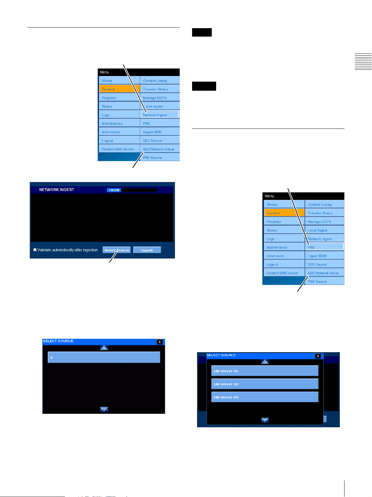
Network Ingest
You can control a DCP Ingest via the network.
To perform one or more
DCP Ingests via the
network, tap Menu,
Content, Network Ingest
in succession. The
NETWORK INGEST
pane appears.
Tap Network Ingest
Content Menu
Note
When performing ingestion of a validated DCP on the
connected SMS, validation will be performed
automatically regardless of whether the Validate
automatically after ingestion checkbox is selected. (See
“Sony Trusted Circle” on page 9.)
Caution
While file transfer for Network Ingest is in progress, Local
Ingest, Network Ingest, and PWI cannot be performed on
the source LMT from which the files are transferred.
PWI (Play While Ingest)
PWI (Play While Ingest) is an ingest method that allows
playback of a single CPL while it is ingesting. Unlike
Local Ingest and Network Ingest, PWI allows you to start
a presentation before the CPL ingest completes.
Chapter 1 User Guide
Select Source
The basic operation steps are exactly the same as for Local
Ingest. For details, see “Local Ingest” on page 34.
However, unlike Local Ingest, for Network Ingest you can
specify the source equipment from which to perform the
Ingest.
Tapping the Select Source button brings up a list of
registered sources.
If Play While Ingest is
Tap P W I
performed while Local
Ingest or Network Ingest
is in progress, Play
While Ingest will take
priority and be
performed. Any Local
Ingest or Network Ingest
operations that were in
progress will resume
after Play While Ingest
completes.
You can control the CPL
Ingest from an external
library server via the
Content Menu
network.
To play content while the CPL ingest is in progress, tap
Menu, Content, and PWI in succession. The PLAY
WHILE INGEST pane appears when you select PWI.
Tapping the Select Source button brings up a list of
registered sources.
The list of sources displayed here is based on S2S Source
registration, described below.
You can select an Ingest source from this screen.
Content
35
Page 36
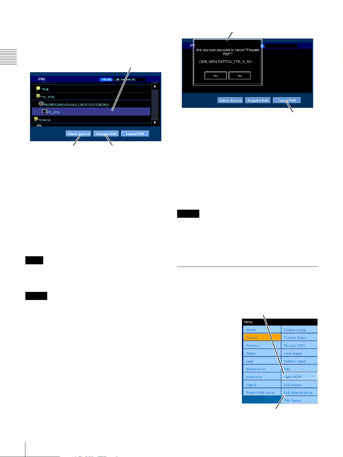
The list of sources displayed here is a list of servers
registered using PWI Source. Specify the server of the
source for which Play While Ingest is to be performed. For
details on PWI Source, see “PWI (Play While Ingest)
Source” on page 39.
Chapter 1 User Guide
Select Source Prepare PWI
Selected CPL
Subfolders and DCPs appear, so tap a DCP to display the
CPL. When you select the CPL for which to perform Play
While Ingest and tap the Prepare PWI button, Play While
Ingest starts or a confirmation dialog box for stopping any
other ingest operations in progress appears. When you tap
Yes, Play While Ingest starts and a notification that the
command has been sent appears.
Confirmation Dialog Box
Cancel PWI
When you tap Yes, Play While Ingest is canceled and a
cancellation results dialog will appear after a few
moments.
After Play While Ingest is canceled, any Local Ingest or
Network Ingest operations that were stopped will resume.
If Play While Ingest is performed again, the Local Ingest
or Network Ingest operations will stop again.
In addition, if Play While Ingest is performed again on a
CPL for which Play While Ingest was canceled, Play
While Ingest will resume from the position at which the
previous operation was canceled.
You can view the progress status of Play While Ingest in
the Now Showing screen. For details, see “Now Showing”
on page 13.
Playback for Play While Ingest is confirmed in the Now
Showing screen and performed from Content Listing. For
details, see “Content Listing” on page 30.
Note
For a standard CPL (2 hours in length), you can start
presentation about 15 minutes after the PWI operation
starts.
Caution
During PWI presentations, the subtitles may take a few
seconds or a few minutes to appear.
Cancel Play While Ingest
When you select the CPL for which Play While Ingest is
being performed and tap the Cancel PWI button, a
confirmation dialog box appears.
Caution
If you perform Local Ingest or Network Ingest for another
DCP after canceling a PWI operation, the DCP of the
canceled CPL may be marked as Failure DCP. If you
want to perform PWI for this CPL again, remove the
Failure DCP status first.
Ingest KDMs
The DCP associated Key Delivery Message (KDM) must
be ingested into the Media Block’s storage system. This
process occurs under control of the Media Block.
To Ingest one or more
KDMs, tap Menu, tap
Content and then tap
Ingest KDM. The
INGEST KDM pane
appears.
While the majority of
KDM operations will
normally take place
using the SMS
Controller, similar
features have been added
to allow operators to
perform KDM Ingest
tasks when the need
arises.
Tap Ingest KDM
Content Menu
36
Content
Page 37
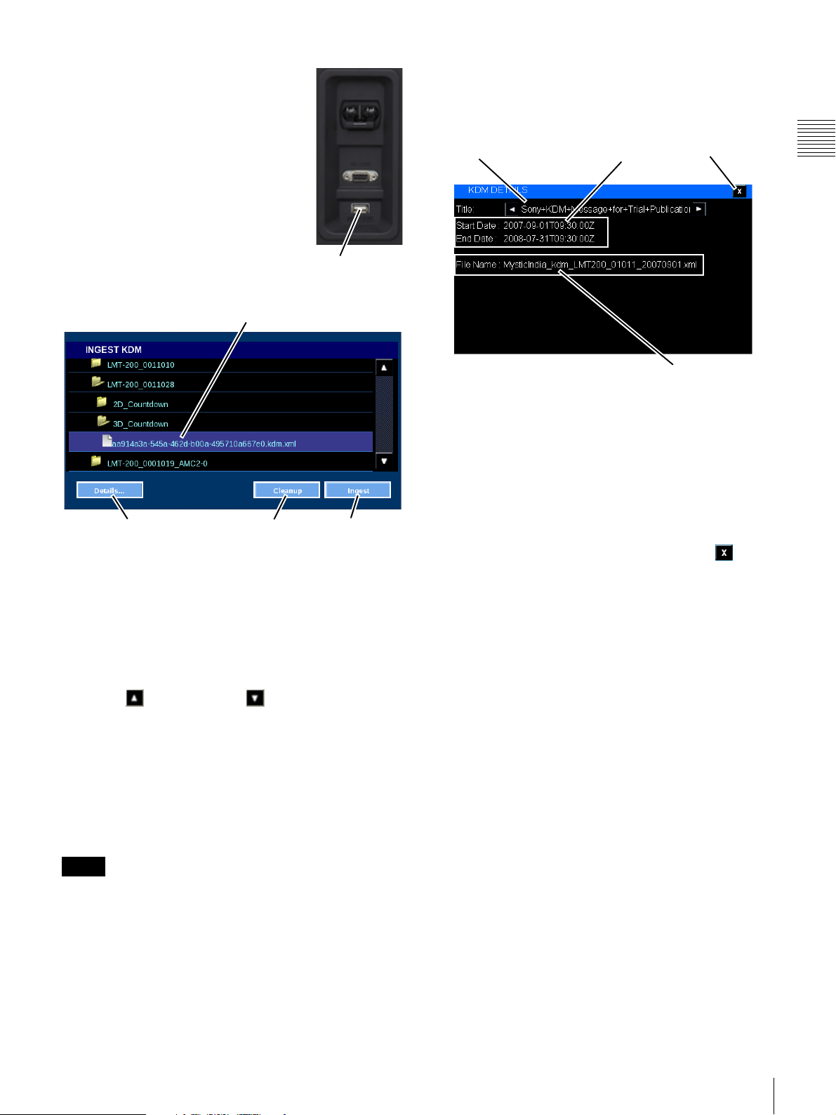
On the rear of the SRX-R320
projector, below the power switch and
RS-232C connector, there is a USB
port labeled INGESTPORT. You can
plug a USB 2.0 Drive into this
connector and it will appear as a folder
in the INGEST KDM list.
From the INGEST KDM pane you can
copy the KDM from its storage
location into the Media Block RAID
Storage. In addition, you can view the
details of the selected KDM.
Selected KDM
Ingest Port
IngestDetails Cleanup
View KDM Details
To view detail information for a specific KDM, locate the
specific KDM in the list. Tap to select the KDM and then
tap Details. The KDM DETAILS popup appears.
KDM Title
KDM Date
Range
KDM FIlename
The KDM DETAILS popup contains information about
the selected KDM. In addition to the Title, the Start
Date (Time) and End Date (Time) showing the valid KDM
Date Range is shown. These dates are the first date and last
date the KDM can be used for decrypting its associated
Content (CPL). The Date and Time is shown in UTC
(GMT) as indicated by the designator “Z”. The Filename
for the selected KDM is also shown.
Close
Chapter 1 User Guide
A USB drive has a folder structure that may contain other
folders or a number of files. Once the USB drive is plugged
in to the Ingest Port, it will appear as a folder in the
INGEST KDM list. The target KDM appears as a file and
can be found in one of the folders on the USB drive.
Alternatively, the KDM file may be located in one of the
folders which have been defined using the SMS Controller
based on fixed locations. To locate the target KDM, tap
Scroll Up or Scroll Down until you find the
desired top level folder and then tap the folder view its
contents. Again, Scroll Up or Scroll Down to locate the
target KDM, tap to select the KDM and then tap Ingest to
begin the ingest process. Since a KDM is usually quite
small, the ingest process should finish quickly. To Ingest
all KDM contained in a folder, select the target folder and
then tap Ingest. The Ingest process is queued and Ingest
proceeds in as a background process.
Note
The folder hierarchy on the transfer media may be more
than one level deep. Continue to navigate folders until the
target KDM has been located.
To close the KDM DETAILS popup, tap Close .
Cleanup (KDMs)
A role restricted function that allows an authorized user to
cleanup orphaned or expired KDMs. KDMs may be
orphaned when the associated DCP is moved to another
Screen Management System or if it is the practice of the
exhibitor to Ingest all KDMs into all available systems.
This function is invoked automatically, and does not
require manual operation under normal circumstances.
Content
37
Page 38
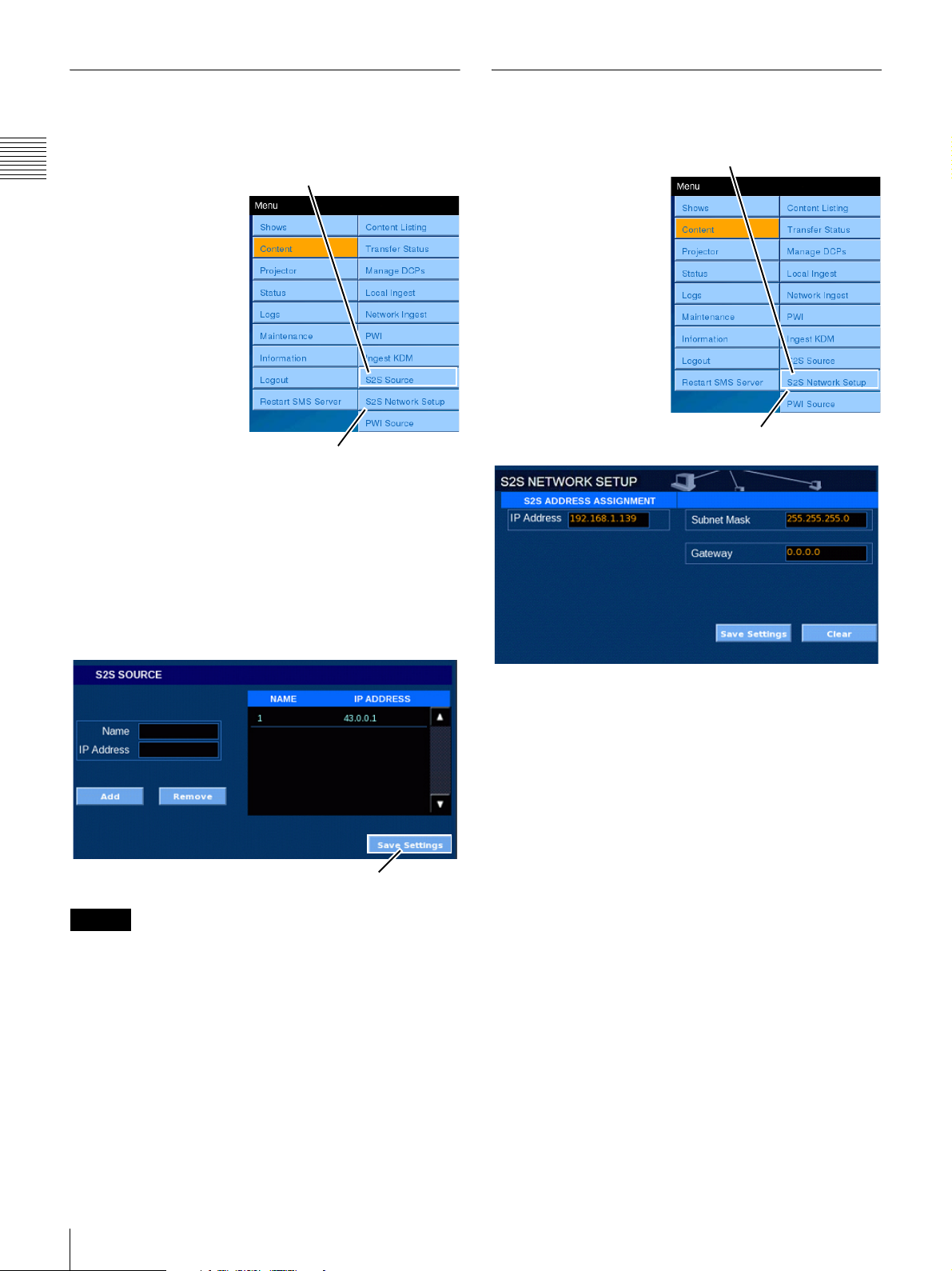
S2S Source
S2S Network Setup
The S2S Source pane shows a list of source addresses that
can be used to perform Ingest via the network.
To access the S2S
Chapter 1 User Guide
Tap S2S Source
SOURCE pane, tap
Menu, Content, S2S
Source in sequence. The
S2S Source selection
opens the S2S SOURCE
pane. Register the IP
address of the equipment
to be used as source for
the Network Ingest.
To register a new source,
enter the pertinent
information in the Name
field and IP Address
field, and tap the Add
button. When completed,
Content Menu
the source will be shown
as registered at right.
To delete a registered source, select it in the list of
registered sources at right, and tap the Remove button. The
selected source is deleted.
You can display S2S address allocation information.
To access the S2S
Tap S2S Network Setup
NETWORK SETUP
pane, tap Menu, Content,
S2S Network Setup in
sequence. The S2S
Network Setup selection
opens the S2S
NETWORK SETUP
pane, which allows
making S2S Network
transfer settings. Values
for the Subnet Mask and
Gateway items can be
set.
Content Menu
After registering and deleting sources, you can save the
settings by tapping Save Settings at the bottom right.
To complete the operation, tap Save Settings.
Save Settings
Caution
Do not use spaces or plus signs (+) in the Name field.
Make the network settings for the DATA IN port here.
Values for the IP Address, Subnet Mask, and Gateway
items can be set. When you tap an input field, the Enter
Address popup window appears. Enter values for the IP
Address, Subnet Mask, and Gateway items.
To set the Static IP address option, tap STATIC in the IP
ADDRESS ASSIGNMENT group and enter the values for
IP Address, Subnet Mask and Gateway.
38
Content
Page 39
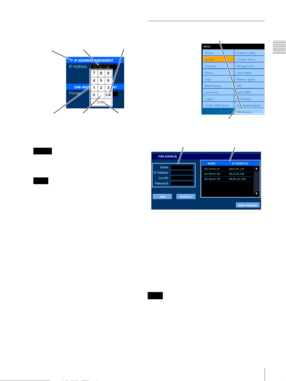
• IP Address
To set a static IP address, tap IP Address and the
Enter Address popup appears.
IP ADDRESS
Assignment
Keypad
Current
IP address
“dot”
CLEAR
Enter
To set a new IP address, tap CLEAR, set the new IP
address by tapping the numbers on the Keypad, and
then tap Accept.
Caution
IP addresses “192.168.1.x” to “192.168.5.x” are
used internally by the system and cannot be used for
the S2S network.
(Clr)
PWI (Play While Ingest) Source
You can view a list of
source addresses for Play
While Ingest.
To access the PWI
SOURCE pane, tap
Menu, Content, and
PWI Source in
succession. The PWI
SOURCE pane appears
when you select PWI
Source.
In this pane, you can
register the names, IP
addresses, account
names, and passwords of
the library servers that
will serve as the ingest
sources during Play While Ingest.
Source to be Newly Registered Registered Sources
Tap PWI Source
Content Menu
Chapter 1 User Guide
Note
Entering the IP addresses from the ENTER
ADDRESS popup uses the “dotted decimal” format
and must include the “dot(s)” as part of the entry.
• Subnet Mask
To set a static Subnet Mask, tap Subnet Mask and
the ENTER ADDRESS popup appears. Tap
CLEAR, set the new IP address by tapping the
numbers on the Keypad, and then tap Accept.
•Gateway
To set a static Gateway, tap Gateway and the
ENTER ADDRESS popup appears. Tap CLEAR,
set the new IP address by tapping the numbers on the
Keypad, and then tap Accept.
After completing the input, tap Save Settings as required.
To register a new source, enter the name and IP address of
the library server that will serve as the ingest source in
Name and IP Address on the left, and enter the name and
password of the account registered to the library server in
UserID and Password. The source will be registered in the
area on the right when you tap the Add button.
If you want to delete a registered source, select the source
you want to delete in the registered list on the right. The
selected source will be deleted when you tap the Remove
button.
After registering and deleting sources, you can save the
settings by tapping Save Settings at the bottom right. Tap
Save Settings when you are finished.
Note
Only FTP servers using FileZilla/VSFTPd can be
registered as library servers. Up to 50 sources can be
registered. You can enter up 256 characters (alphanumeric
characters and symbols, excluding spaces and + signs) for
Name. You can enter up to 50 characters (alphanumeric
characters, underscores, hyphens, and periods) each for
UserID and Password.
Content
39
Page 40
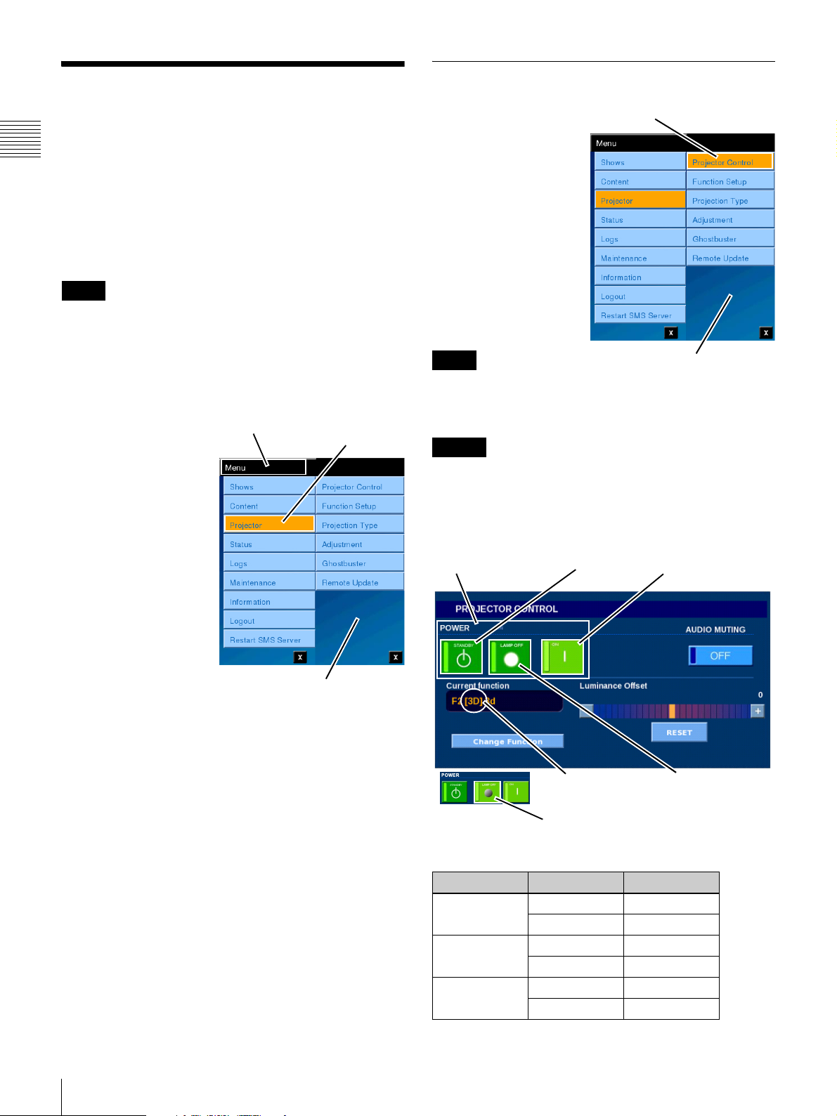
Projector
Basic control of selected Projector system functions are
Chapter 1 User Guide
available from the Projectionist Terminal. In the
SRX-R320 based system, reference to the “Projector”
includes only the projector portion of the Auditorium Unit.
When the Projector is in STANDBY various subsystems
of the auditorium unit are still operational. To Shutdown
the Auditorium Unit refer to “Restart SMS Server” on
page 69.
Note
When the Projector is in STANDBY mode the system
remains active and accessible via either the Projectionist
Terminal or the SMS Controller application. When the
Auditorium Unit has been Shutdown you must execute a
Power ON sequence which is described in “Restart SMS
Server” on page 69.
The Projector menu
selection allows you to
access information and
control functions for the
following items.
• Projector Control
• Function Setup
• Projection Type
•Adjustment
• Ghostbuster
• Remote Update
Tap M e nu
Tap P r ojector
Projector Control
The PROJECTOR
CONTROL pane
contains basic controls in
addition to Current
Function select and the
Luminance Offset
control. To access
Projector Controls, tap
Menu, tap Projector and
then tap Projector
Control. The
PROJECTOR
CONTROL pane
appears.
Note
Changes made on the
PROJECTOR CONTROL pane effects as soon as the
selection is made.
Caution
DO NOT REMOVE AC-MAINS POWER TO SHUT
DOWN THE SYSTEM OR SET THE PROJECTOR
BREAKER TO OFF AS LAMP COOLING WILL BE
LOST AND THE RISK OF LAMP FAILURE IS
INCREASED.
POWER Group
Tap Projector Control
STANDBY
Projector Menu
(Projector) ON
(Lamp) ON
To access Projector
menus, tap Menu and
then tap Projector. The
Projector Menus
appear.
Projector Menu
From PROJECTOR CONTROL you can place the
Projector system in STANDBY, return it to ON
(operational mode), turn off the LAMP, DOUSE the image
output, recall a preset configuration, and adjust the
Luminance Offset applied to the current presentation from
the Digital Cinema projection system.
From FUNCTION SETUP you can modify a limited
number of projector settings; Lamp Power, Zoom, Focus
and Electrical V Shift, and save these new settings to the
Current Function.
From Projection Type you designate whether the projector
is configure for 2D or 3D presentation.
From Adjustments you perform projector alignment
operations.
From Ghostbuster, you can check whether the Ghostbuster
function is ON/OFF.
LAMP ON3D Function
LAMP OFF
The following table provides a guide to the possible
Projector State/State transition possibilities.
Current Mode Transitio n New Mode
STANDBY OK ON
NO LAMP OFF
ON OK STANDBY
OK LAMP OFF
LAMP OFF OK STANDBY
OK ON
40
Projector
Page 41
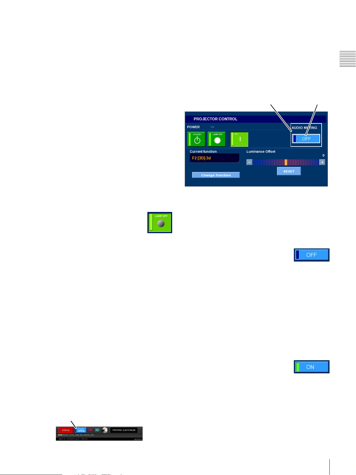
Set Projector To ON
To place the Projector in the ON mode, tap Menu, tap
Projector, tap Projector Control and then in the Power
group tap ON. The system will transition from STANDBY
mode to ON mode and the projection lamp will be
illuminated.
Set Projector To STANDBY
To place the Projector to STANDBY mode from LAMP
ON mode, tap Menu, tap Projector, tap Projector
Control and then, in the Power group, tap STANDBY.
You will be prompted to confirm the action. Tap YES to
confirm.
The system will transition from an operational mode to
STANDBY. Internal fans will continue to run until the
lamp and lamp assembly has cooled. Do NOT set the
power switch (circuit breaker) to OFF before the indicator
shows that the projector is in STANDBY mode.
Set Projector LAMP OFF/ON
The Projector Lamp may be turned OFF while allowing
the Projector to continue in an operational mode. When the
Lamp is turned OFF the imaging panels remain powered
and under temperature control.
The LAMP OFF/ON button is available only
when the Projector is in the ON mode. To turn
the Projector Lamp OFF, tap Menu, tap
Projector, tap Projector Control and then in
the Power group tap LAMP OFF. The Lamp OFF button
goes dark (as shown to the right), Change Function and
Calibrate Luminance RESET become unavailable, but the
Projector remains ON as indicated by the ON button
remaining illuminated. (See inset in the previous
illustration.) Temperature stabilization remains applied to
the imaging panels when the LAMP OFF feature is used in
place of setting the Projector to STANDBY.
Once the Projector Lamp in ON, Change Function and
Calibrate Luminance RESET become available.
Douse the Projector
The DOUSER control function in the PROJECTOR
CONTROL screen serves the same purpose as the
“douser” on the film projector. In fact it works in much the
same way by placing an opaque blade in the output light
path.
When you set the projector DOUSER to CLOSE the
auditorium screen goes dark. However, this only applies to
the image portion of the presentation. The audio portion of
the presentation continues and must be muted using the
separate Audio Muting control.
DOUSER Control
Audio Muting
The AUDIO MUTING control function in the
PROJECTOR CONTROL screen causes the sound output
from the Auditorium Unit to be silenced.
When you set the AUDIO MUTING to ON the sound to
the auditorium is silenced. However, this only applies to
the sound portion of the presentation. The image portion of
the presentation continues and must be Doused using the
DOUSER control.
AUDIO MUTING OFF/ON
Audio Muting ON (Silence)
The Audio Muting control is an alternate action button
whose current state is indicated by the status label and a
status indicator in the OFF/ON button. When the control’s
status indicator is out (label shows OFF) the audio output
is enabled and the current presentation sound is available
in the auditorium.
To silence the audio output, tap Menu,
tap Projector, tap Projector Control and
then, in the AUDIO MUTING block, tap
the alternate action OFF/ON button. The sound output is
silenced, the auditorium is silenced, and the control button
label changes to ON and its status indicator is lit (see inset
in illustration). The audio output is muted, regardless of
the current presentation status.
Audio Muting OFF (Sound ON)
Audio Muting is activated by an alternate action control
button whose current state is indicated by the status
indicator located in the ON/OFF button. When the
indicator is illuminated (label shows ON) the sound output
is silenced.
To restore the sound output, tap Menu,
tap Projector, tap Projector Control and
then, in the AUDIO MUTING block, tap
the alternate action ON/OFF button. The sound output is
restored, the auditorium sound is restored, the control
button label changes to OFF and the button status indicator
is dark.
Chapter 1 User Guide
Projector
41
Page 42
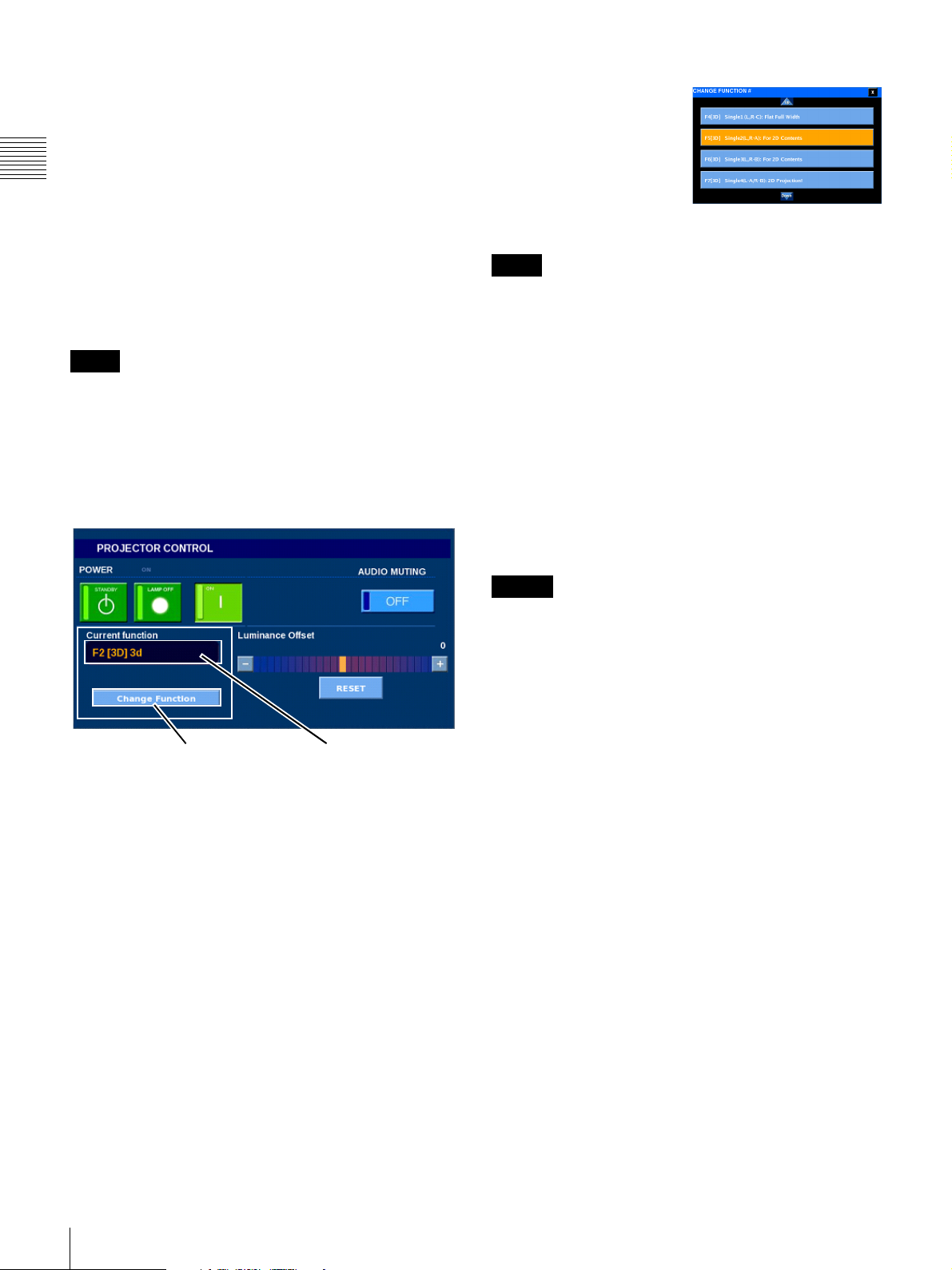
Change Projector Function
Changing the Current FUNCTION selection (F1 to F20) is
done using Change FUNCTION on the PROJECTOR
CONTROL screen. Functions can be used to recall stored
settings which affect the projector setup. Each
Chapter 1 User Guide
FUNCTION configuration is set using the SRX
Controller
presentation. In addition, a limited number of settings
associated with a specific FUNCTION can be configured
using the FUNCTION SETUP screen (see page 43).
The configurations are stored and available on a pop-up
accessed from the Projector Control screen. These are
single button FUNCTION selections.
Note
A FUNCTION can be associated with a CPL and,
indirectly, an SPL using the SMS Controller. In this way
the same configuration is recalled whenever the associated
Content Element is presented.
MANUALLY SELECTING A FUNCTION WILL
CHANGE THE PROJECTOR SETTINGS UNTIL A
NEW FUNTION IS SELECTED.
1
application and is set to optimize the on-screen
Select Function
Projector Functions are
related to the specific
Projection Type, i.e., a 3D
FUNCTION can only be
applied when the Projection
Type is set to Single 3D. A
3D FUNCTION contains
[3D] in the Function Name.
Note
Selection of a Projector Function incompatible with the
Projection Type will result in a warning message
appearing and the selected FUNCTION not applied. Click
OK to close the message.
To select a Function, verify the correct Projection Type is
indicated adjacent to the Lamp Indicator, tap Menu, tap
Projector, tap Projector Control and then tap Change
Function. The Change Function pop-up window appears.
Tap the UP ARROW or DOWN ARROW until the
specific FUNCTION is visible and then tap the desired
FUNCTION button. Extended Function Names may be
truncated. If there is a question as to the FUNCTION
verify the name to FUNCTION number relationship using
the SMS Controller.
Change Function Current Function
Manual FUNCTION selection is made from a pop-up that
appears when you tap Change FUNCTION on the
PROJECTOR CONTROL screen. To access the
PROJECTOR CONTROL screen, tap Menu and then tap
Projector Control. The Current FUNCTION selection is
indicated in the Function group.
FUNCTION selection may be the result of an association
between a CPL and a FUNCTION or by including a
Function in the Show Playlist.
Caution
The projector adjustments and settings stored as the
selected FUNCTION are immediately applied
2
to the
projector. During this period of time the auditorium screen
may go dark. No confirmation message of the FUNCTION
key selection is displayed. Also, there is no “undo”. If the
previous setup was the results of a FUNCTION setting
applied based on a CPL association, projector settings are
changed to the new settings. Adjustments made but not
saved on the FUNCTION SETUP pane will be lost.
The Projector FUNCTION selected is retained until a
different FUNCTION selection is made or until a different
FUNCTION is selected as a result of presenting a CPL
with a different FUNCTION association or a SPL that
includes FUNCTION Commands.
The FUNCTION selected will be the Current Function
appearing on the FUNCTION SETUP screen and will be
modified based on projector settings when Save to
FUNCTION is executed.
42
1.The SRX Controller exercises direct control over the
projector and therefore should not be used at the same time
the Projectionist Terminal or SMS Controller is in
operation.
Projector
2.Assumes that the appropriate Projection Type has been
configured.
Page 43
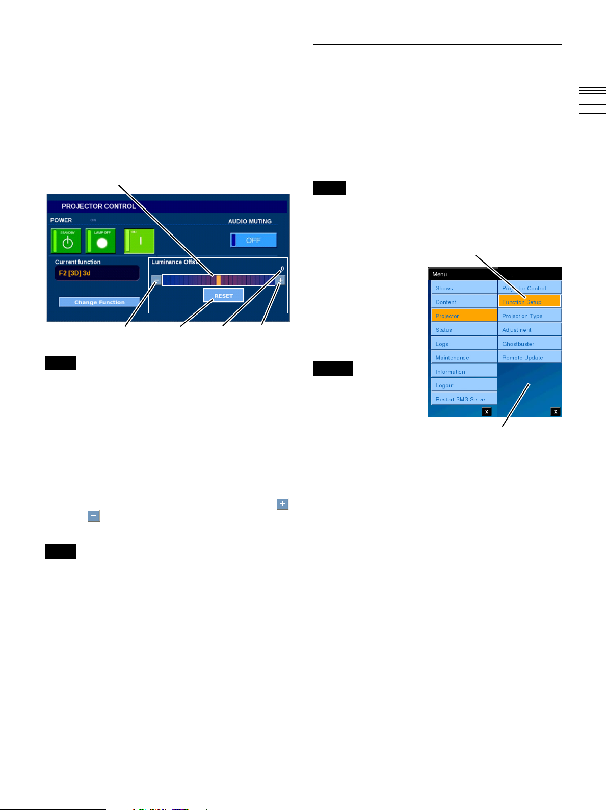
Set Luminance Offset
During installation of the SMS the Lamp Power is adjusted
to provide the desired screen illumination. This value can
be set in a FUNCTION as the calibrated lamp brightness
for an associated aspect ratio.
On occasion, it is desirable to increase the screen
luminance, i.e., raise lamp brightness, to meet special
presentation needs. The Luminance Offset slider allows
you to make this temporary (offset) adjustment.
Luminance Offset
Control
Function Setup
To ease the projector setup task the SRX-R320 Projectors
allow you to save specific configuration settings under
twenty selectable FUNCTIONs (F1 through F20). The
majority of the projector settings must be configured and
saved to a FUNCTION using the SRX Controller
application. However, some settings may require
adjustment of a more immediate nature. These are
available to you on the FUNCTION SETUP screen.
Note
Controls in the ADJUST PROJECTOR group are
unavailable when the Projection Type is set to “Single
3D”.
1
Chapter 1 User Guide
RESET
Note
Value RaiseLower
The Luminance Offset will remain in effect until you tap
RESET which returns the offset to “0” (zero).
Luminance Offset (Adjust)
The Luminance Offset control is a slider which allows you
to make temporary adjustments to increase or decrease the
screen luminance value within the predefined limits of
Lamp Power for the bulb.
To adjust the Luminance Offset, tap Menu, tap Projector,
tap Projector Control and then either touch and drag the
Luminance Offset control or press and hold the Plus
or Minus buttons until the desired screen luminance
(image brightness) is obtained.
Note
While adjusting Luminance Offset affects lamp
brightness, the Lamp Power indicated on the FUNCTION
SETUP screen is not changed.
Luminance Offset RESET
To return the screen luminance to the value stored in the
currently selected FUNCTION, tap Menu, tap Projector,
tap Projector Control and then tap RESET located below
the Luminance Offset slider.
A limited number of
Tap Function Setup
adjustments are available
on the FUNCTION
SET-UP pane. To access
Function Setups, tap
Menu, tap Projector and
then tap Function Setup.
The FUNCTION
SET-UP pane appears.
Caution
Any changes made to
adjustments on the
FUNCTION SET-UP
pane change the
presentation as soon as
Projector Menu
the adjustment is made.
However, unless “Saved” prior to leaving the
FUNCTION SETUP screen the changes will not be
present the next time the same FUNCTION is selected.
Changes which are Saved to the FUNCTION will be
reflected in the settings returned the next time the indicated
FUNCTION is selected on the Projector Control panel or
recalled when an SPL includes a CPL associated with the
FUNCTION.
From the FUNCTION SETUP screen you can set LAMP
POWER and adjust image related settings (ADJUST
PROJECTOR). The settings are stored for later recall
using the indicated FUNCTION (Current Function).
Configure Function
From the FUNCTION SET-UP pane you adjust selected
functions and can save the changed values to the Current
Function (refer to “Change Projector Function” on page
42).
1.The SRX Controller exercises direct control over the
projector and therefore should not be used at the same time
the Projectionist Terminal or SMS Controller is in
operation.
Projector
43
Page 44
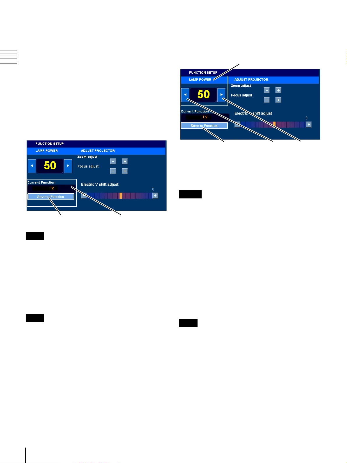
Verify Current/Target Function
MAKE SURE THAT THE CORRECT (TARGET)
FUNCTION, e.g., F2 2D Flat, APPEARS IN “Current
Function” BEFORE MAKING ANY ADJUSTMENT ON
THIS SCREEN.
Chapter 1 User Guide
Once changes are saved to the Current Function THERE
IS NO “UNDO” and the changes you have made will
affect the presentation every time the FUNCTION is
recalled using either the Projector control screen or when
the FUNCTION is associated with a CPL as part of a Show
or SPL.
To change the Current Function refer to “Change
Projector Function” on page 42. The Current Function
indicates the FUNCTION selected either manually or by
CPL to FUNCTION association.
To adjust LAMP POWER, tap Menu, tap Projector, tap
Function Setup, and then either tap, or press and hold, the
LEFT ARROW (Lower) or RIGHT ARROW (Raise)
while viewing the projected image on the screen.
LAMP POWER
Save to FUNCTION
Note
Current Function
When a FUNCTION is selected on the PROJECTOR
CONTROL pane it may take some seconds to complete the
process as some adjustments are mechanical in nature, e.g.,
Zoom, Focus, etc. During this time the auditorium screen
may be dark.
If you make changes to settings and prior to saving the
changes exit the FUNCTION SET-UP screen the changes
will be discarded. However, the changed settings on the
projector remain until a new FUCNTION is selected.
Note
While adjustments will immediately affect the projector
operation they are temporary and, unless Saved, will be
lost when another FUNCTION is selected.
Adjust Lamp Power
Screen Luminance vs. Lamp Power
Lamp Power Raise/Lower is used to adjust the bulb
brightness and therefore the screen luminance. The Lamp
Power indicator displays a value that is linked to the
Maximum and Minimum Lamp Power parameters (%)
included in the Serial Code.
Save to FUNCTION
Lower
Raise
Lamp Power changes are made in increments of 1%. The
Indicator shows the current Lamp Power setting.
To save the adjusted Lamp Power in the Current Function,
tap Save to FUNCTION.
Caution
Once changes are saved to the Current Function THERE
IS NO “UNDO” and the changes you have made will
affect the presentation every time the indicated
FUNCTION is recalled using either the Projector control
screen or when the FUNCTION is associated with a CPL
as part of a Show or SPL. This is especially significant for
Lamp Power because the bulb brightness, i.e., screen
luminance value stored in the Current Function may have
been set to a standard value, e.g., 14 ft-L using a
luminance measurement device.
If you make changes to settings and, prior to saving the
changes, exit the FUNCTION SET-UP screen the changes
will be discarded. However, the settings will be retained on
the projector until a new FUCNTION is selected.
Adjust Projector
Note
Controls in this group are unavailable when Projection
Type is set to “Single 3D”.
When you configure the Projector for an aspect ratio, e.g.,
2.39:1 (CinemaScope
®
), 1.85:1 (VistaVision®) or
1.33:1 (Academy), the SRX-R320 sets the lens zoom to a
defined point so the larger of the image dimension fills the
screen. During projector installation the lens zoom setting
is adjusted using internal Projector Test Patterns or a
standard test DCP. Zoom positions for common aspect
ratios would be stored in selected FUNCTIONS
1.A number of projector settings are stored including the
lamp brightness/luminance value so image brightness can
be maintained regardless of aspect ratio.
1
using the
44
Projector
Page 45
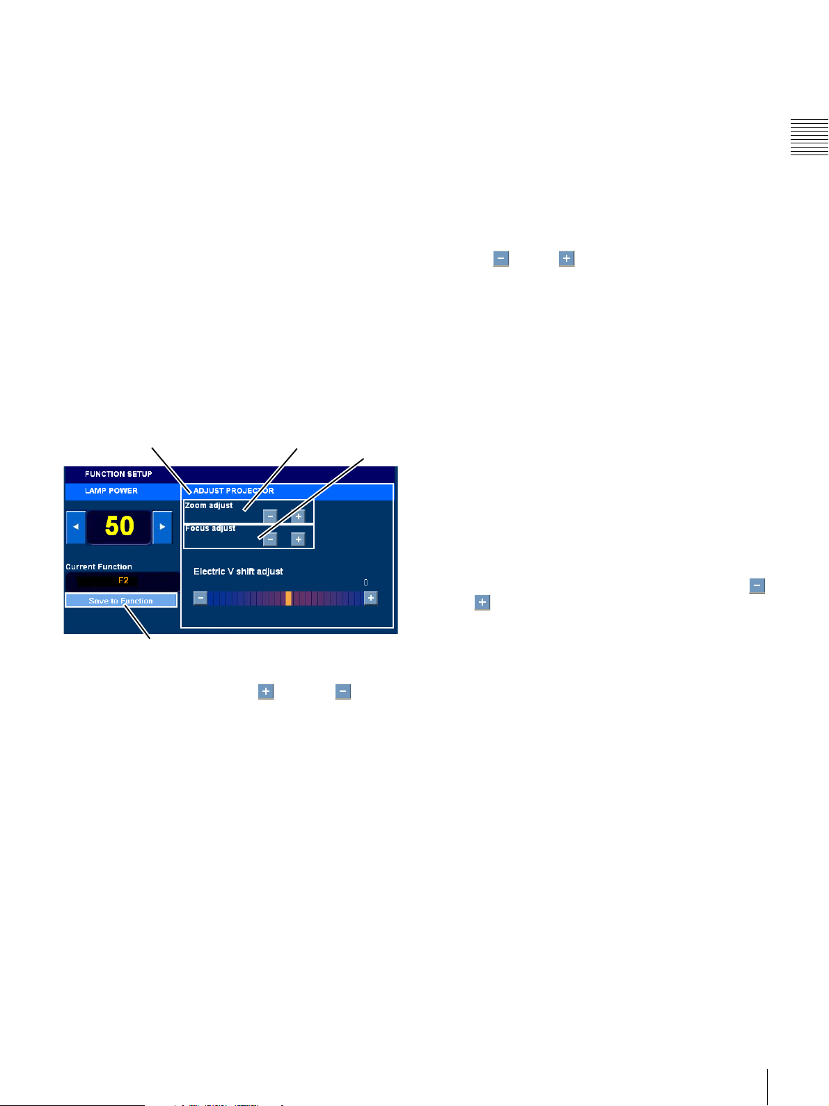
SRX Controller1. Once these settings are memorized to a
FUNCTION the Screen Management System software can
associate these FUNCTIONS with a CPL which recalls
lens settings when the CPL is included in a presentation.
Lens focus can also be stored in a FUNCTN.By adjusting
the focus to the best position and then saving the
FUNCTION, you can easily re-establish proper focus later
by recalling the FUNCTION.
Electric V shift applies a vertical position offset to the
image. This setting is stored in the FUNCTION and, when
the Screen Management System associates the
FUNCTION with a CPL, a vertical offset is recalled and
applied to the image when the CPL is included in a
presentation. This vertical offset of the image is used to
adjust for any slight displacement in the vertical center of
the image when different aspect ratios are included in a
single presentation.
The ADJUST PROJECTOR group comprises the lens
mechanical adjustments (Zoom and Focus) and the image
Electric V shift adjustment.
Zoom (Image Size)
2
To use projection lenses that allow you to zoom to properly
size the image to the auditorium screen. The Zoom setting
is associated with the Current Function and recalled when
that FUNCTION is selected on either the PROJECTOR
CONTROL screen or the associated CPL is included in a
presentation. Zoom is a mechanical adjustment of the
projector lens and should not be confused with any kind of
image manipulation creating a zoom effect.
To adjust Zoom (the image size), tap Menu, tap Projector,
tap Function Setup, and then either tap, or press and hold,
the Minus or Plus button associated with Zoom
while observing the projected image on the screen. This
adjustment is normally done using the CinemaScope/Vista
Projector Test Patterns (see “Test Pattern (Select)” on
page 47). However, it may be necessary to observe the
actual content (CPL) while setting Zoom to insure that the
screen is properly filled while still not spilling the image
onto the screen mask or surround. In this case, it is
recommended you create a new FUNCTION which is
specific to the CPL using the SRX Controller application.
Chapter 1 User Guide
ADJUST PROJECTOR Zoom
Save to FUNCTION
Focus
To operate controls in the ADJUST PROJECTOR group,
you tap or press and hold the Plus or Minus buttons.
Prior to adjusting the Zoom, Focus or Electric V shift,
verify that Current Function displays the desired target so
when the adjustment is saved it is applied to the correct
FUNCTION.
Focus (Image Sharpness)
The Focus setting is associated with the Current Function
and recalled when that FUNCTION is selected on the
PROJECTOR CONTROL screen or associated with the
CPL. This is a mechanical adjustment of the projector lens
and should not be confused with any kind of electrical
focus adjustments.
To adjust Focus, tap Menu, tap Projector, tap Function
Setup, and then either tap, or press and hold, the Minus
or Plus button associated with Focus while observing
the projected image on the screen. Adjusting Focus is
usually realized using a DCP containing a suitable test
image and typically. Observing actual Show content while
setting focus is not recommended.
1.The SRX Controller exercises direct control over the
projector and therefore should not be used at the same time
the Projectionist Terminal or SMS Controller is in
operation.
2.Not available when Projection Type is set to “Single
3D”.
Projector
45
Page 46
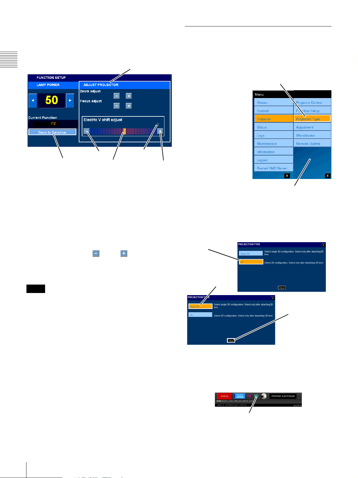
Electric V shift
Allows you to electrically compensation for vertical image
displacement when the aspect ratio of the image is changed
from 2.39:1 to 1.85:1. Refer to Projector documentation
for additional details.
Chapter 1 User Guide
ADJUST PROJECTOR
Projection Type
The PROJECTION TYPE pane contains basic controls
which allow you to configure the Projector for either 2D or
3D (Stereoscopic) operation. The Auditorium Unit
supports presentation of 3D (Stereoscopic) Content.
Value
Raise
Save to Function
Lower
Electric V shift Control
The Electric V shift control shows the relative vertical
“position” of the image on the auditorium screen and is
associated with the Current Function. In addition, this
control has a numeric display which allows you to position
the image to a known location based on the content aspect
ratio.
To adjust the Electric V shift, tap
Function Setup
, and then touch & drag the
Menu
, tap
Projector
Electric V shift
, tap
control to a new setting and release. To make incremental
adjustments to the Electric V shift setting, either tap, or
press and hold, the
Minus
or
Plus
button associated
with Electric V shift while observing the projected image on
the screen. A numerical value is shown to allow for easy
resetting of Electric V shift to a previous value.
Note
Response to setting the Electric V shift will experience
some delay. You should use the Control (Indicator) and
numeric Value to place the image in the approximate
position desired.
The presentation of 3D
Tap Projection Type
Content is realized by
mounting a specially
designed lens in lieu of
the standard (2D) lens.
This lens is designed to
combine two images
(right eye/left eye), apply
the appropriate circular
polarization, and then
combine the two images
through a single
objective lens for screen
presentation. After
attaching the 3D lens to
the Auditorium Unit the
Projector Menu
Projection Type must be
set to “Single 3D”.
To access Projection Type, tap Menu, tap Projector and
then tap Projection Type. The Projection Type pane
appears.
Current
Projection Type
(2D)
Tap to Select
Single 3D
Projection Type
Tap to Close
46
When the PROJETOR TYPE pane appears it will show the
currently set Type. In the above example, the PROJETOR
TYPE pane opens with the Projection Type set to 2D. To
change the Projection Type, tap Single 3D and then tap
Close and you return to the NOW SHOWING pane.
3D Indicator
Note the presence of the 3D Indicator when the Projection
Type is set to “Single 3D”.
Projector
Page 47
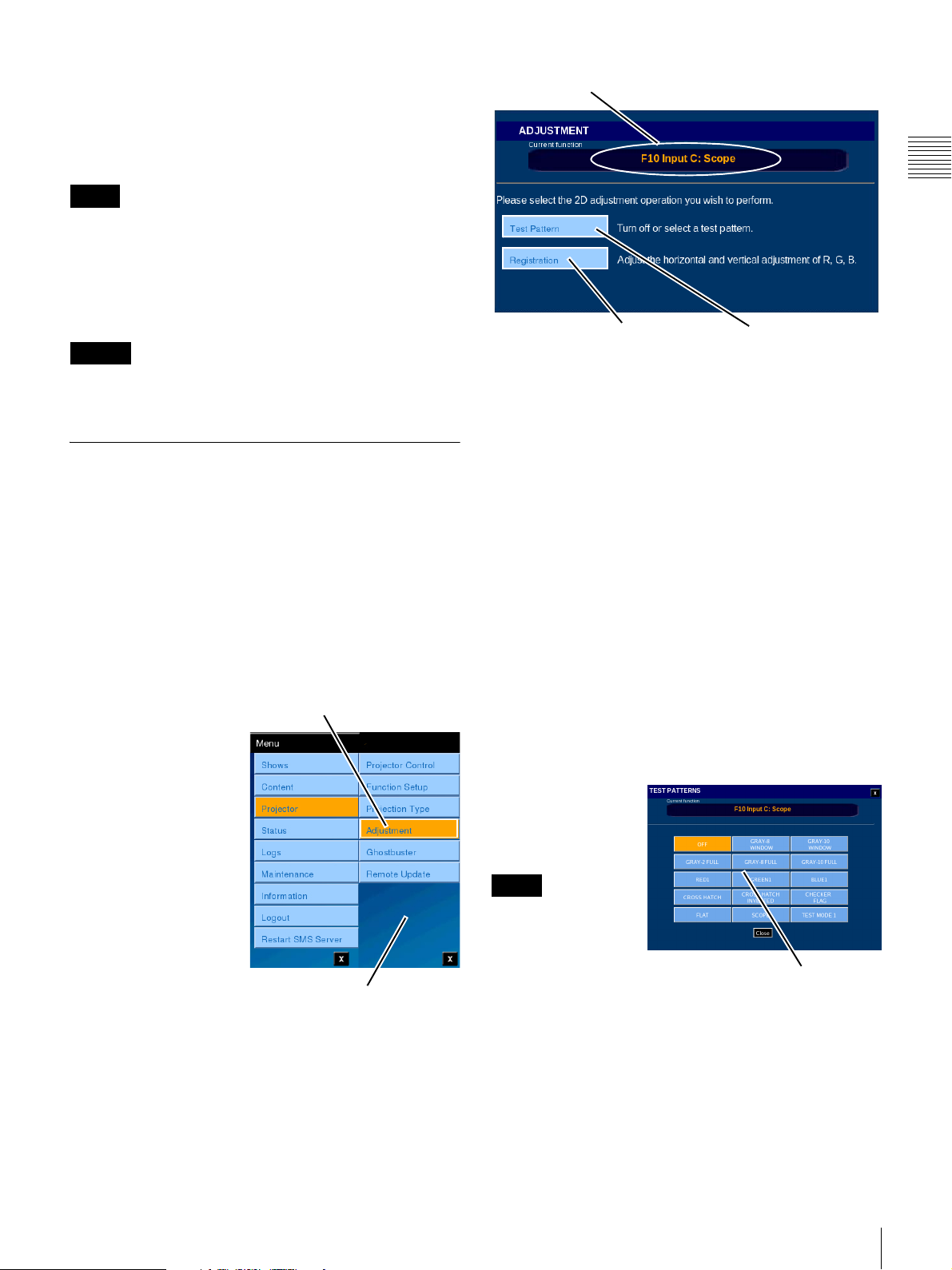
Projector FUNCTION
Once the Projection Type has been set it is necessary to
select an appropriate Projector FUNCTION. The
FUNCTOIN is related to Projection Type and if not
correctly set presentation cannot be realized.
Note
It is important that when the SPL presentation is to be
started by Schedule the correct Projector FUNCTION
included in a Show Playlist be appropriate to the Projection
Type. An incorrectly selected FUCNTION will cause the
presentation to fail. A Warning Message will appear
approximately 20 minutes before the Show Start Time.
Caution
If the Projection type is “Single 3D,” schedule playback of
SPLs that do not include CPLs cannot be performed.
Adjustment
The Projector Adjustment functions available are dependant
on the Projection Type previously set. In addition to the
difference in Previously, registration adjustment and Blue
images and the selection of Test Patterns used during these
adjustments required the use of the SRX Controller
application. In Version 2.20 and later of the SMS these
functions have been added to features available via the
Projectionist Terminal.
Projection Type 2D
To access
ADJUSTMENT, tap
Menu, tap Projector and
then tap Adjustment.
The ADJUSTMENT
pane based on a 2D
Projection Type appears.
The ADJUSTMENT
pane contains a display
showing which
FUNCTION is currently
selected
1
, and controls
allowing access to TEST
PATTERNS and to
REGISTRATION
ADJUSTMENT.
Tap A d j u stment
Projector Menu
Current FUNCTION
Tap to Access
Registration Adjustment
Tap to Access
Test Patterns
Test Pattern (Select)
A number of Test Patterns are available for use during the
Registration Adjustment process. In addition, other test
patterns are available for other adjustment processes, e.g.,
Image Sizing, etc.
To select a specific Test Pattern, tap Test Pattern on the
ADJUSTMENT pane. The TEST PATTERNS popup
appears. Patterns available are:
•OFF
• Gray-8 and Gray-10 (centered white block at 80%
and 100% white respectively)
• Gray-2 FULL, Gray-8 FULL and Gray-10 FULL
(20%, 80% and 100% white, Full Screen)
• Red1, Blue1, and Green1 (centered block)
• Crosshatch and Crosshatch Inverted
• Checkered Flag
• Flat (image sizing reference)
• CinemaScope (image sizing reference)
•Test Mode 1
Insure that OFF is
selected when
adjustments are
complete.
Note
When making a Test
Pattern selection,
other Projector
Settings remain
unchanged but the
Tap Desired Pattern
to Select
selected test pattern
appears on the
screen.
Chapter 1 User Guide
1.Access to the Adjustment pane is only available when
the Projector is in ON mode, the Projection Type is 2D and
the selected FUNCTION is a 2D FUNCTION.
Insure that OFF is selected when adjustments are
complete.
Projector
47
Page 48
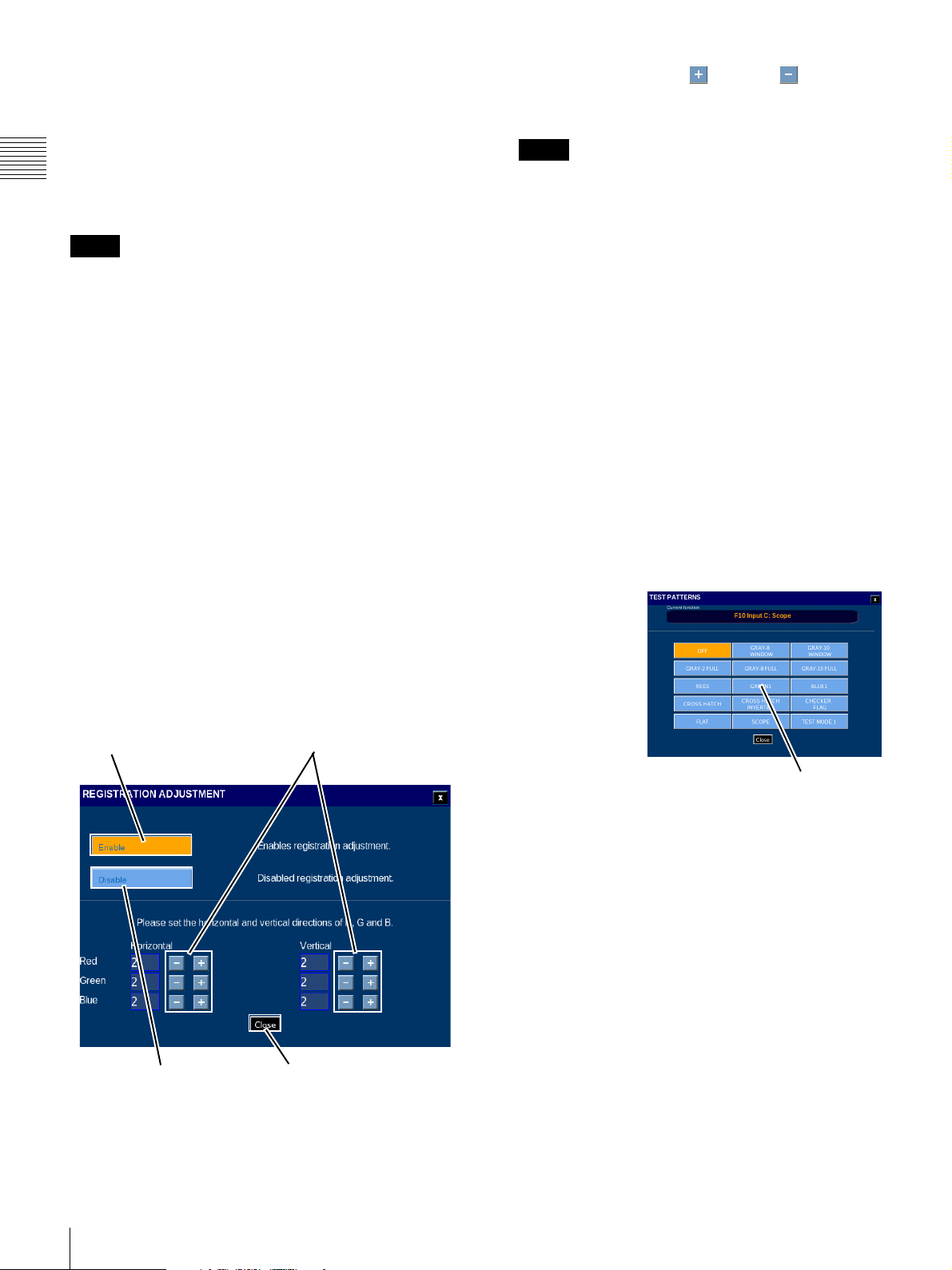
Registration Adjustment
Previously, adjustments to the registration positioning
(X/Y Axis) was realized only under the pre-defined
Theater Setup login “trsetup” or by using the SRX
Controller application. This adjustment is also available
under Projector menu and Adjustment submenu via the
Chapter 1 User Guide
Projectionist Terminal. Access to the Adjustment
functions are role restricted.
Note
Registration Adjustments can only be performed in 2D
mode, Prior to performing Registration Adjustment set the
Projector to ON mode, set Projection Type to 2D and
select a 2D FUNCTION. Allow a minimum of 30 minutes
warm-up to insure that the imaging devices have reach
their operating temperature. Also, prior to verify that focus
is optimized. Recall the correct lens focus by selecting an
appropriate FUNCTION or re-adjust using FUNCTION
SETUP (Role restricted).
To perform Registration Adjustment, tap Registration on
the ADJUSTMENT pane. The Registration Adjustment
screen appears.
Adjustments made during the Registration Adjust process
are applied immediately to the projector. You must be able
to view the auditorium screen in detail as picture
movement is in pixel increments.
1
To begin the Registration Adjustment process, tap
Enable.
The Registration Adjustment Horizontal and Vertical
controls become available.
Tap +/- to set Horizontal or
Tap t o E nable
Vertical position of Image.
Tap the appropriate Plus or Minus button to
align the Red, Green and Blue images as observed on
the auditorium screen.
Note
Insure that Lens Focus is optimized prior to starting
the registration process. In some cases it may be
beneficial to use a white sheet of paper placed flat
against the screen so you can see the black/white
transition to verify lens focus (use crosshatch pattern)
and also to make it easier to see registration errors.
2
Other Test Patterns may be used during the
Registration Adjustment process.
Since the adjustments made are set immediately tin the
projector you can exit the Registration Adjustment
pane to change the Test Pattern as needed. To select a
different Test Pattern, tap Close and
you wish to leave Registration Enabled, tap YES.
you are prompted if
Tap Test
Patterns, select the new Test Pattern and then tap
Close. The ADJUSTMENT pane reappears.
3
Tap Registration and continue with the adjustment
process.
Test Pattern (Change)
To select a test
pattern image
from the
ALIGNMENT
pane, tap Test
Pattern. The
TEST
PATTERN
popup appears.
Tap Disable before
Closing
Tap to Close
Registration adjustment range is from +2pixels to 2 pixels with an increment of adjustment of +/-1 pixel.
The CHECKER
FLAG Pattern is
Tap Desired Pattern
to Select
normally used
for registration
adjustment. However, the CROSSHATCH or
INVERT CROSSHATCH Pattern may also be useful
when reviewing the final settings.
Normally, the CHECKER FLAG Pattern will be used for
Registration Adjustment.
48
Projector
Page 49
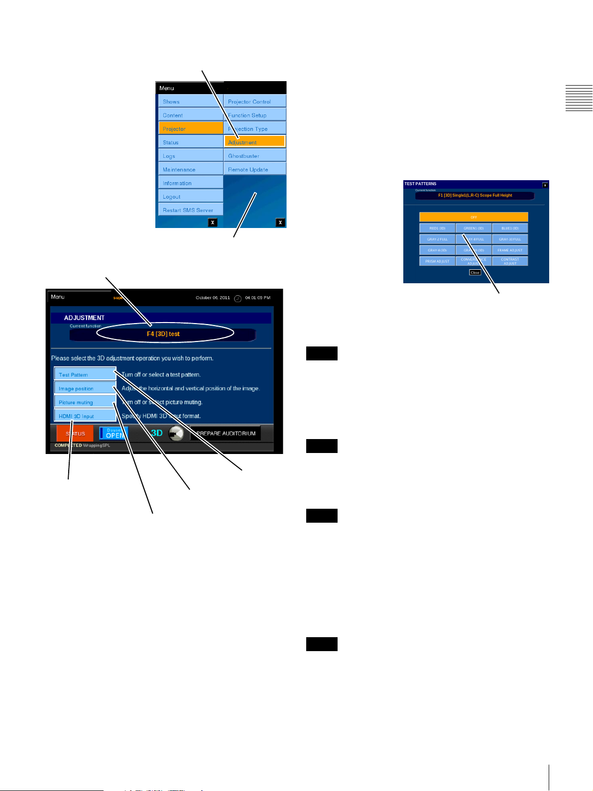
Projection Type 3D
To access
ADJUSTMENT, tap
Menu, tap Projector and
then tap Adjustment.
The ADJUSTMENT
pane based on a 3D
Projection Type appears.
The ADJUSTMENT
pane contains a display
showing which
FUNCTION is currently
selected
allowing access to TEST
PATTERNS, IMAGE
POSITION, and
PICTURE MUTING.
1
, and controls
Current FUNCTION (3D)
Tap A d j u stment
Projector Menu
To select a specific Test Pattern, tap Test Pattern on the
ADJUSTMENT pane. The TEST PATTERNS popup
appears. Patterns available are:
•OFF
• RED1, GREEN1 and BLUE1 (all 3D)
• GRAY-2 FULL, GRAY-8 FULL and GRAY-10
FULL (20%, 80% and 100% white, Full Screen)
• GRAY-8, GRAY-10, (3D) and FRAME ADJUST
• PRISM ADJUST, CONVERGENCE ADJUST and
CONTRAST ADJUST
.Insure that OFF is
selected when
adjustments are
complete
To select the Test
Pattern image, tap
Menu, tap
Projector, tap
Adjustment, and
then tap Test
Pattern. The TEST
Tap Desired Pattern
to Select
PATTERN popup
appears.
Chapter 1 User Guide
Tap to Access
HDMI 3D Input
Tap to Access Image
Position Adjustment
Tap to Access Picture Muting
Tap to Access
Test Patterns
Note that the Current Function is a 3D FUNCTION.
Test Pattern (Select)
A number of Test Patterns are available for use during the
IMAGE POSITION adjustment process. Generally, these
are specific to adjusting the projector for presentation of
3D content. Additional Test Patterns for general projector
alignment are available when the Projection Type is set to
2D.
1.Access to the Adjustment pane is only available when
the Projector is in ON mode, the Projection Type is 3D and
the selected FUNCTION is a 3D FUNCTION.
Note
When making a Test Pattern selection, other Projector
Settings remain unchanged but the selected test pattern
appears on the screen.
Make sure that OFF is selected when adjustments are
complete.
Note
Test Pattern CONTRAST ADJUST is enabled only when
Input C is selected.
Image Position (3D) Adjustment
Note
Image Position Adjustments can only be performed in 3D
mode and should not be attempted by anyone not fully
familiar with the process.
Adjusting the image position is a new function related to
support of 3D (stereoscopic) presentation. Image Position
adjustment has been introduced to support alignment of the
right-eye/left-eye images. Access to Image Position is
Role restricted.
Note
Prior to performing Image Position Adjustment set the
Projector to ON mode, set Projection Type to 3D and
select the appropriate 3D FUNCTION. Allow a minimum
of 30 minutes warm-up to insure that the imaging devices
have reach their operating temperature.
Projector
49
Page 50
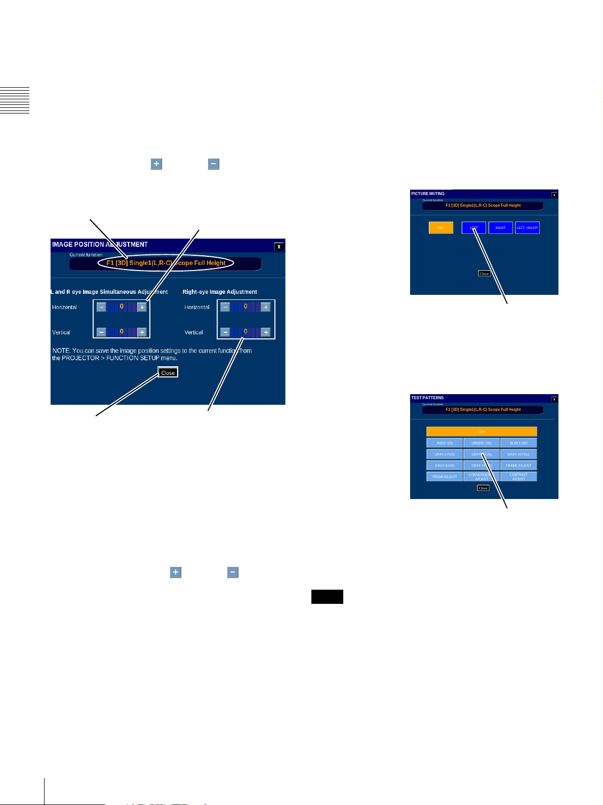
To perform Image Position adjustment, tap Image
Position on the ADJUSTMENT pane. The Image Position
Adjustment screen appears.
Adjustments made during the Image Position Adjust
process are applied immediately to the projector. You must
Chapter 1 User Guide
be able to view the auditorium screen in detail as picture
movement is in pixel increments.
1
To realize the Image Position adjustment process, use
the appropriate Plus or Minus button to
properly position the images as observed on the
auditorium screen.
Current Function (3D)
Tap +/- to set Horizontal or
Vertical position of both
Right & Left Eye Images
3
To assist in the process of positioning the righteye/left-eye images you can block the image by
muting the right, left or both images. To block an
Image, tap Close
. Tap Picture Muting, select the
Image to be muted and then tap Close.
The ADJUSTMENT pane reappears.
4
Tap Image Position and continue with the adjustment
process.
Picture Muting
To select the
picture to be
muted from the
ADJUSTMENT
pane, tap
Picture Muting.
The PICTURE
MUTING pane
appears. Tap the
button for the
eye to be muted.
The image for
Tap Desired Eye
to be muted
the selected eye
is muted and you can proceed with adjustment of the
image position for the remaining eye image.
Tap to Close
Tap +/- to set Horizontal or
Vertical position of ONLY the
Right Eye Image
The adjustment range is;
•L&R eye
Horizontal: -70 to +70
Vertical: -20 to +20 or -120 to +120
•R eye
Horizontal: -600 to +600
Vertical: -20 to +20
Then unit of adjustment is 1 pixel.
Tap the appropriate Plus or Minus button to
position the combined Right-eye and Left-eye images
and then adjust the position of the Right-eye image
only as observed on the auditorium screen.
2
Various Test Patterns are used during the Image
Position adjustment process.
Since the adjustments made are set immediately in the
projector you can exit the Image Position Adjustment
pane to change the Test Pattern as needed. To select a
different Test Pattern, tap Close
. Tap Test Patterns,
select the new Test Pattern and then tap Close. The
ADJUSTMENT pane reappears.
Test Pattern (Change)
To select a test
pattern image
from the
ALIGNMENT
pane, tap Test
Pattern. The
TEST
PATTERN
popup appears.
Once the Right-eye
and Left-eye images
Tap Desired Pattern
to Select
are properly
positioned set both
Picture Muting and Test Pattern to OFF then tap Close on
the Image Position Adjustment pane.
Note
The Image Position settings can be saved in the currently
selected projector FUNCTION.
Specifying the 3D Input Format
To specify the 3D format for input to the HDMI board, tap
HDMI 3D Input on the ADJUSTMENT pane. The
SELECT INPUT FORMAT pane appears.
50
Projector
Page 51
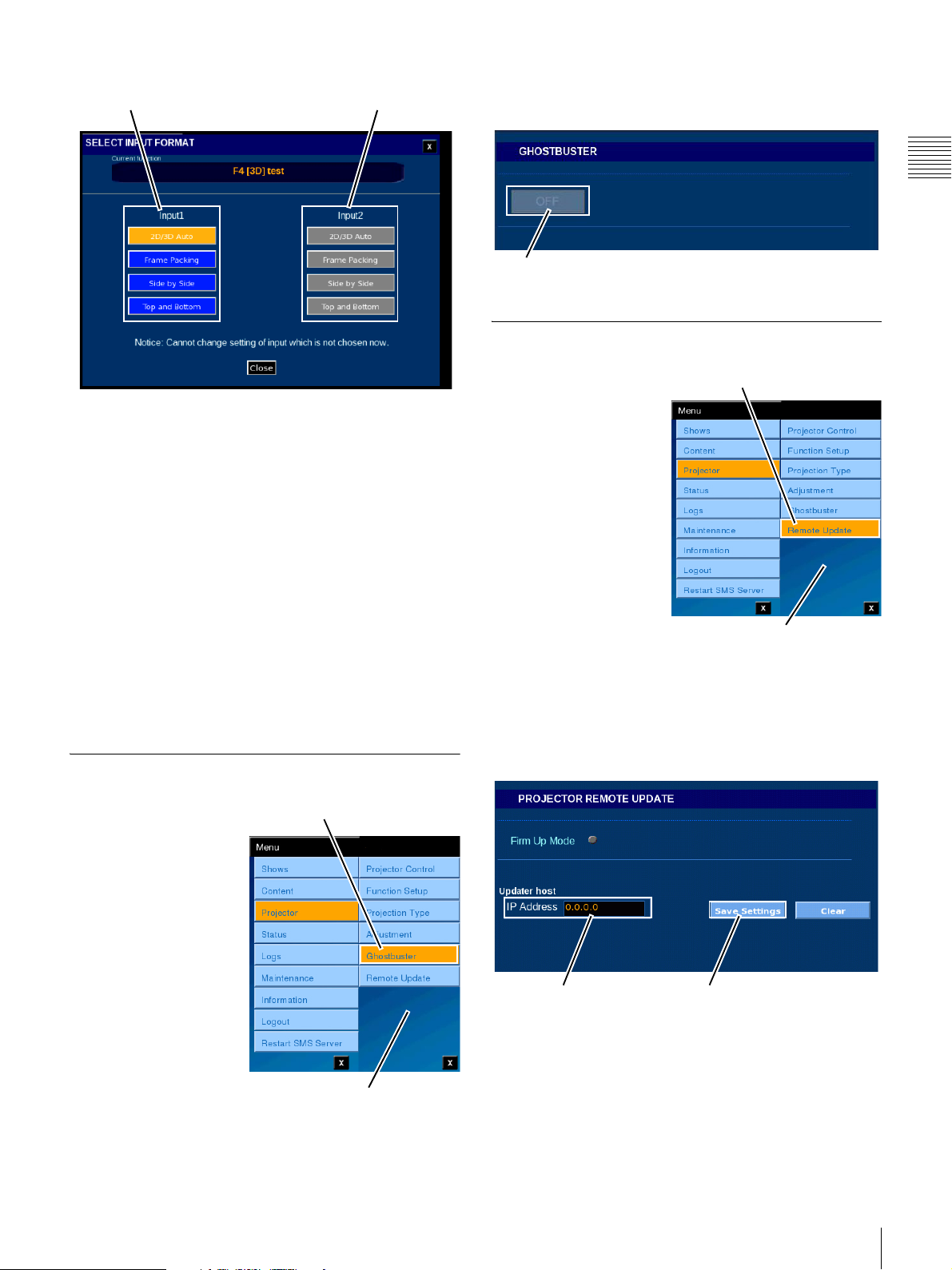
Input1 (Input A)
3D format
Input2 (Input B)
3D format
The Ghostbuster function can be verify ON/OFF.
The function can only be enabled or disabled during Lamp
ON status.
Chapter 1 User Guide
ON/OFF
Projector Remote Update
The 3D format for Input1 (Input A) is specified on the left
and the format for Input2 (Input B) on the right.
The currently selected 3D format is displayed in orange,
and the selectable 3D formats are displayed in blue. If a
board is not installed, or is installed but is not recognizable,
the corresponding formats are displayed in gray.
Tap a blue button to select the 3D format of the input signal
for the specified input (Input1/Input2).
Select the topmost 2D/3D Auto for normal operation. Use
this button for systems that cannot recognize 3D formats.
You can change the 3D format for each input. However,
when changing input format, it is necessary that the target
input be selected on the projector (the image from the input
for which you wish to change format is displayed by the
current projector).
Ghostbuster
To access
GHOSTBUSTER, tap
Menu, tap Projector and
then tap Ghostbuster.
Tap Ghostbuster
To make settings for
Tap Remote Update
updating the projector
software via the network,
tap Menu, Projector,
Projector Remote
Update in sequence. The
PROJECTOR REMOTE
UPDATE pane appears.
Projector menu
Here you can make settings for remotely updating the
projector software via the network. To specify the IP
address of the server where the software is located, tap the
IP Address field. The Enter Address popup window
appears. You can enter the IP address here.
Projector Menu
IP Address Save Settings
Projector
51
Page 52
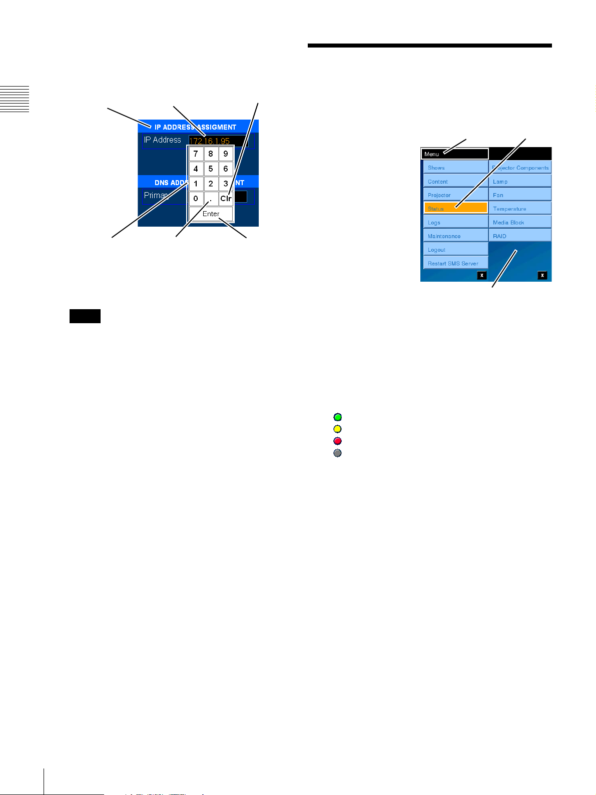
• IP Address
To set a static IP address, tap IP Address and the
Enter Address popup appears.
Status
IP ADDRESS
Assignment
Chapter 1 User Guide
Keypad
Current
IP address
“dot”
To set a new IP address, tap CLEAR, set the new IP
address by tapping the numbers on the Keypad, and
then tap Accept.
Note
Entering the IP addresses from the ENTER
ADDRESS popup uses the “dotted decimal” format
and must include the “dot(s)” as part of the entry.
After IP address entry is complete, tap Save Settings as
required.
CLEAR
(Clr)
Enter
You can view various status indicators for the Auditorium
Unit from the Projectionist Terminal.
The Status menu
Tap Menu
Tap Status
selection allows you to
access the following
status information for the
following areas and
subsystems in the
Auditorium Unit.
• Projector
•Lamp
•Fan
• Temperature
•Media Block
• RAID
Additional information
Status Menu
may be contained in documentation specific to the various
sub-system.
To view the status information, tap Menu and then tap the
specific sub-system from the available Status Menus. The
Status panes present views into the selected sub-system.
Indicators found on the Status panes have three possible
states. They are:
(Green) - Operation Normal
(Yellow) - Warning
(Red) - Error
(Gray) - State Unknown
The Status section describes information available when a
specific Status Menu is selected. Refer to the specific
Menu section for additional details.
52
Status
Page 53
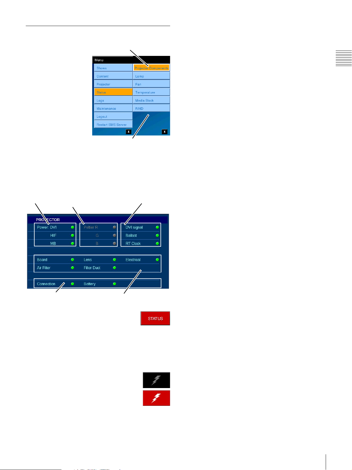
Projector Status
To access the Status pane
for the Projector, tap
Menu, tap Status and
then tap Projector
Components.
The Projector pane
appears which displays
status indicators for
major components in the
projector sub-system.
They are:
•Power
• Peltier
• DVI Signal
•Ballast
• RT Clock Battery
• Board, Lens, Electrical
Tap Projector Components
Status Menu
Power
The SRX-R320 projectors are equipped with 3 signal
processors. They are:
•DVI
The signal processor for externally originated DVID signals.
•HIF
The signal processors for externally originated
HD/DC-SDI signals.
•MB
The signal processor for Media Block originated
signals.
Peltier1 - Thermal Devices
Power to the thermal control devices associated with the
Red, Green, and Blue (R,G,B) imagers is monitored and
the status is shown on this screen.
Chapter 1 User Guide
When Projector is selected from the Status Menus the
PROJECTOR status pane is displayed.
Power
Connection and Battery
Peltier
Board, Lens, Electrical,
Air Filter and Filter Duct
DVI Signal
Ballast
RT Clock
The STATUS button shown to the right
appears on all SMS Controller windows and
provides immediate access to the Status
Selector/Warning indicators. When any Warning
condition exists the STATUS button will appear RED as
shown. To view which system area requires attention, tap
the STATUS button and the Status Selector/Warning
buttons appear.
DVI signal, Ballast, RT Clock Battery
Indicates the status for specific areas on the projector.
• DVI signal
Indicates that the format of an externally applied
DVI-D signal has been verified against the
configuration set using the SRX Controller
application.
• Ballast
Indicates the status of operating conditions of
devices associated with the Lamp Ballast.
• RT Clock Battery
Indicates the status/health of the battery for the Realtime Clock located in the projector.
Board, Lens, Electrical, AIr FIlter, Filter
Duct
Indicates the status of additional subsystems in the
projector.
The system monitors the number of hours of use of Air
Filters in the system enclosure. The timers for replacement
of these filters are manually reset to zero (0) at the time of
replacement.
To view which projector area requires
attention, tap the STATUS button and the
Status Selector/Warning buttons appear. As
illustrated to the right, the Projector
Selector/Warning indicator will be RED
when an error condition exists. To view the
Projector Status, tap the Projector Warning icon.
Connection and Battery
“Connection” indicates the status of physical and logical
network connections between the Media Block and
1.A Peltier device, is a solid-state active heat pump which
transfers heat from one side of the device to the other side
against the temperature gradient (e.g., from cold to hot),
with consumption of electrical energy. In the SRX-R320,
this is used to control the imager temperature.
Status
53
Page 54
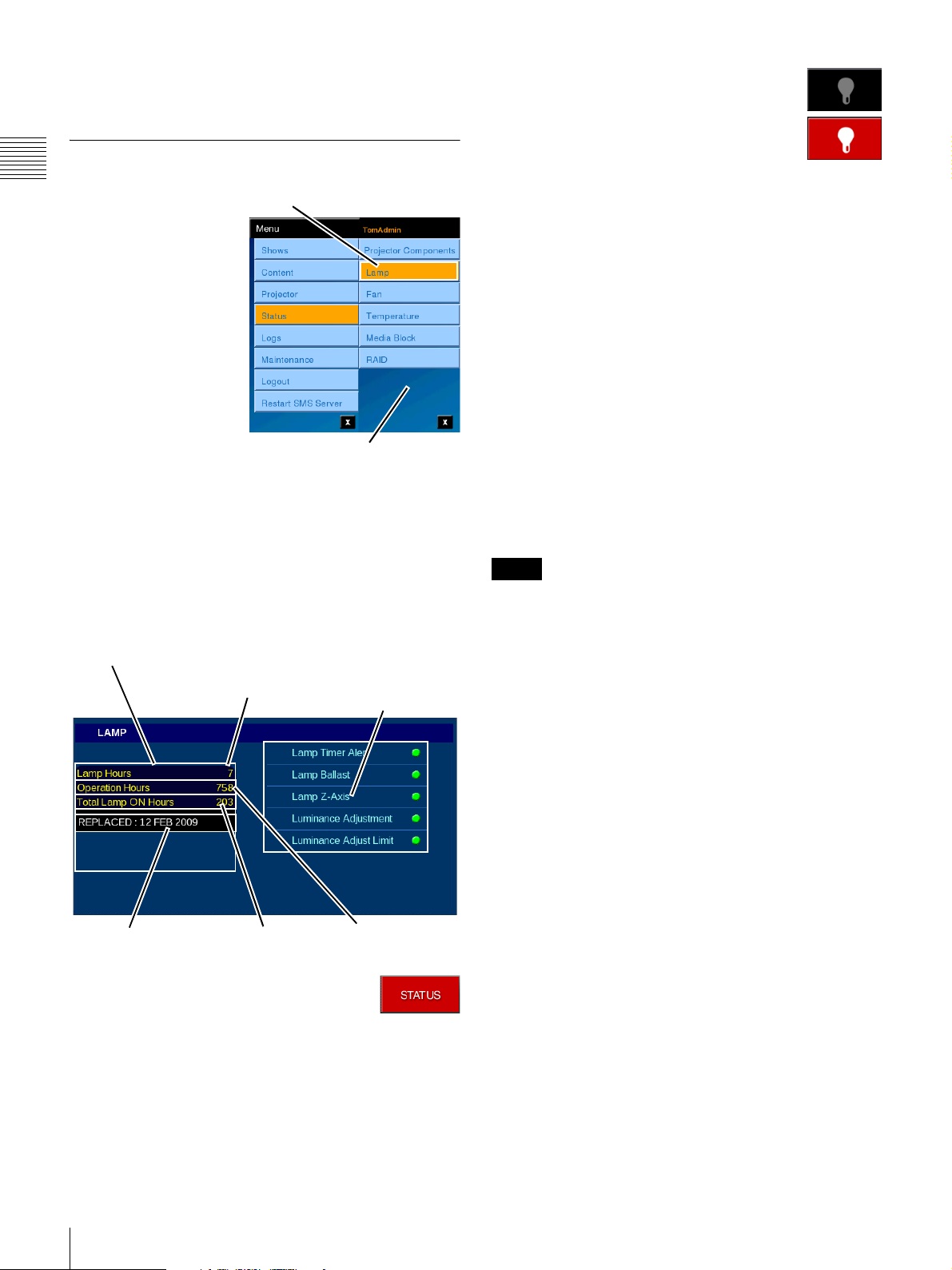
Projector. “Battery” indicates the status of the Projector’s
Secure Silicon battery.
Lamp Status
Chapter 1 User Guide
The SRX-R320
projectors are single
lamp systems. To access
the Status pane for the
Projector Lamp, tap
Menu, tap Status and
then tap Lamp.
The LAMP pane appears
which displays both
Lamp and Projector
hours of use and the Date
of the most recent Lamp
Replacement.
In addition, Status
indicators are present for the following:
• Lamp Timer Alert
• Lamp Ballast
•Lamp Z-Axis
• Luminance Adjustment
• Luminance Adjust Limit
Lamp Information
Tap L a m p
Lamp
Hours
Status Menu
Lamp Timer Alert
Lamp Ballast
Lamp Z-Axis
Luminance Adjustment
Luminance Adjust Limit
As illustrated to the right, the Lamp
Selector/Warning indicator will be RED
when an error condition exists. To view the
Lamp Status, tap the Lamp Warning icon.
Lamp Information
This Lamp Information group shows the Lamp Hours,
total Operation Hours (projector), Lamp ON Timer, and
the most recent date the lamp was REPLACED.
Lamp Hours
The value shown for Lamp Hours is an effective value
which uses the Lamp Power value to adjust the actual
Lamp ON hours downward when operating the lamp at
less than 100% power. This value is reset to “0” (zero)
when the lamp is replaced and a new Lamp Serial Code is
entered.
Operation Hours
The value shown for Operation Hours is the total number
of hours when AC Mains are applied to the Projector.
Total Lamp ON Hours
The value shown for Total Lamp ON Hours is the actual
number of hours when the Lamp is in the ON mode.
Note
The lamp should be replaced prior to exceeding
recommended operating hours. Refer to the projector
documentation for additional information.
Lamp Indicators
Lamp Timer Alert
The Lamp Timer Alert is green when the lamp hours are
less than the recommended operating hours. The indicator
will display yellow when the hours are exceeded.
(Lamp) Replaced
Total Lamp ON
Hours
Operation Hours
The STATUS button shown to the right
appears on all Projectionist Terminal
windows and provides immediate access to
the combined Status Warning indicators and selector
buttons. When any Warning condition exists the STATUS
button will appear RED as shown. To view which system
area requires attention, tap the STATUS button and the
Status Warning/Selector buttons appear.
54
Status
Lamp Ballast
The indicator is green when the status of the power
(ballast) for the projection lamp is normal. The indicator
will display red when an error is detected.
Lamp Z-Axis Adjust
The Lamp Z-Axis indicator is green when the status the
Z-axis adjustment motor used for lamp positioning is
normal. The indicator will display yellow when an error is
detected.
Luminance Adjust
The Luminance Adjust indicator is green when the
luminance adjustment feature is operating normally. The
indicator will display yellow when an error is detected.
Luminance Adjust Limit
This indicator is reserved for future expansion of projector
features. Currently this indicator is green at all times.
Page 55
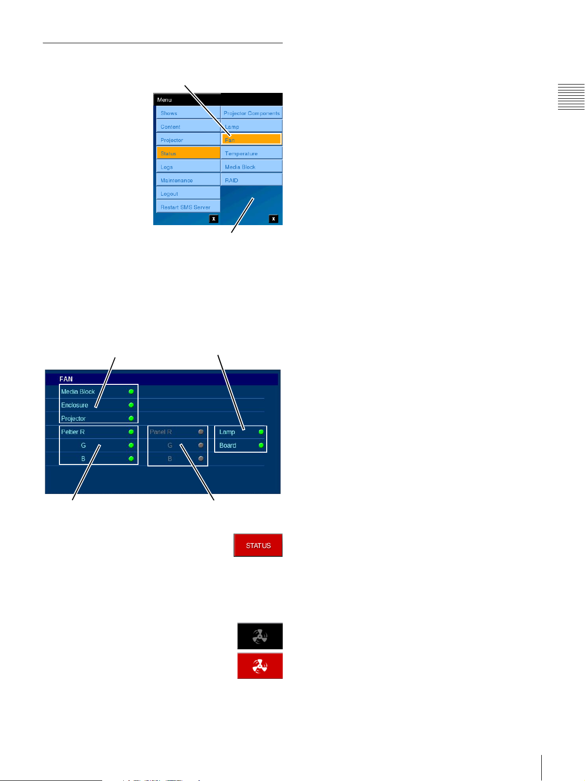
Fan Status
To access the Status
pane for System Fans,
tap Menu, tap Status
and then tap Fan.
The Fan pane appears
displaying status
indicators for fan
operation in the
Auditorium Unit and
areas in the Projector
sub-system. They are:
•Media Block,
Enclosure, Projector
• Peltier (R/G/B)
•Panel (R/G/B
Imagers)
•Lamp
• Board
When Fan Status is selected from the Status Menu the
FAN STATUS information is displayed.
Media Block
Enclosure
Projector
Tap Fan
Status Menu
Lamp & Board
Subsystem Fans
Three major areas in the Auditorium Unit are monitored
for operation of the fans. They are; the Media Block, the
Auditorium Unit Enclosure, and the Projector.
Media Block
Two dual-fan exhaust units (A & B) are located at the rear
of the LMT-300 Media Block. These fan units also contain
the back-up battery for the Media Block memory. Do Not
remove both the A & B fans units at the same time.
The Media Block indicator is green when the status of the
Fan units are normal. The indicator will display red when
an error is detected.
Enclosure
The Enclosure (Auditorium Unit) contains two main air
circulation fans. One is located in the Lower (base) area
and the other is located in the Upper area. Both fans are
monitored and their status is shown on the Enclosure
indicator. The indicator will display red when an error is
detected.
Projector
A number of areas in the Projector have fans dedicated to
maintain operating temperatures. Areas having a major
affect on the quality of image presentation or lamp
environment have indicators for those specific areas (see
“Projector Component Fans”). The status of fans in other
projector areas are shown on the Projector indicator. The
indicator will display red when an error is detected.
Chapter 1 User Guide
Peltier Devices
Red, Green, Blue
Panel (Imaging) Devices
Red, Green, Blue
The STATUS button shown to the right
appears on all SMS Controller windows and
provides immediate access to the Fan Status
information. When any Warning condition exists the
STATUS button will appear RED as shown. To view
which projector area requires attention, tap the STATUS
button and the Status Selector/Warning buttons appear.
As illustrated to the right, the Fan
Selector/Warning indicator will be RED
when an error condition exists. To view
status information for the Fans, tap the Fan
Warning icon.
Projector Component Fans
Peltier (R, G, B)
Peltier devices are used to maintain the optimum operating
temperature of R, G, and B areas of the prism assembly.
The indicator will display red when an error is detected.
Panel (R, G, B Imaging)
Maintaining correct operating temperature in the imaging
area is critical to the quality of presentation. Additional
fans provide air circulation for each of the imaging areas
(R, G, B). The indicator will display red when a Panel fan
error is detected.
Lamp
Maintaining adequate air circulation in the Lamp housing
is critical to realizing the expected lamp life. If lamp
temperature is allowed to rise beyond specification then a
possible lamp explosion can occur. The indicator will
display red when a Lamp fan error is detected.
Board
Adequate air circulation for the Projector control board is
maintained by fans within the Projector subsystem. The
indicator will display red when a Board fan error is
detected.
1
1.The RX-R320 does not use a Panel fan.
Status
55
Page 56
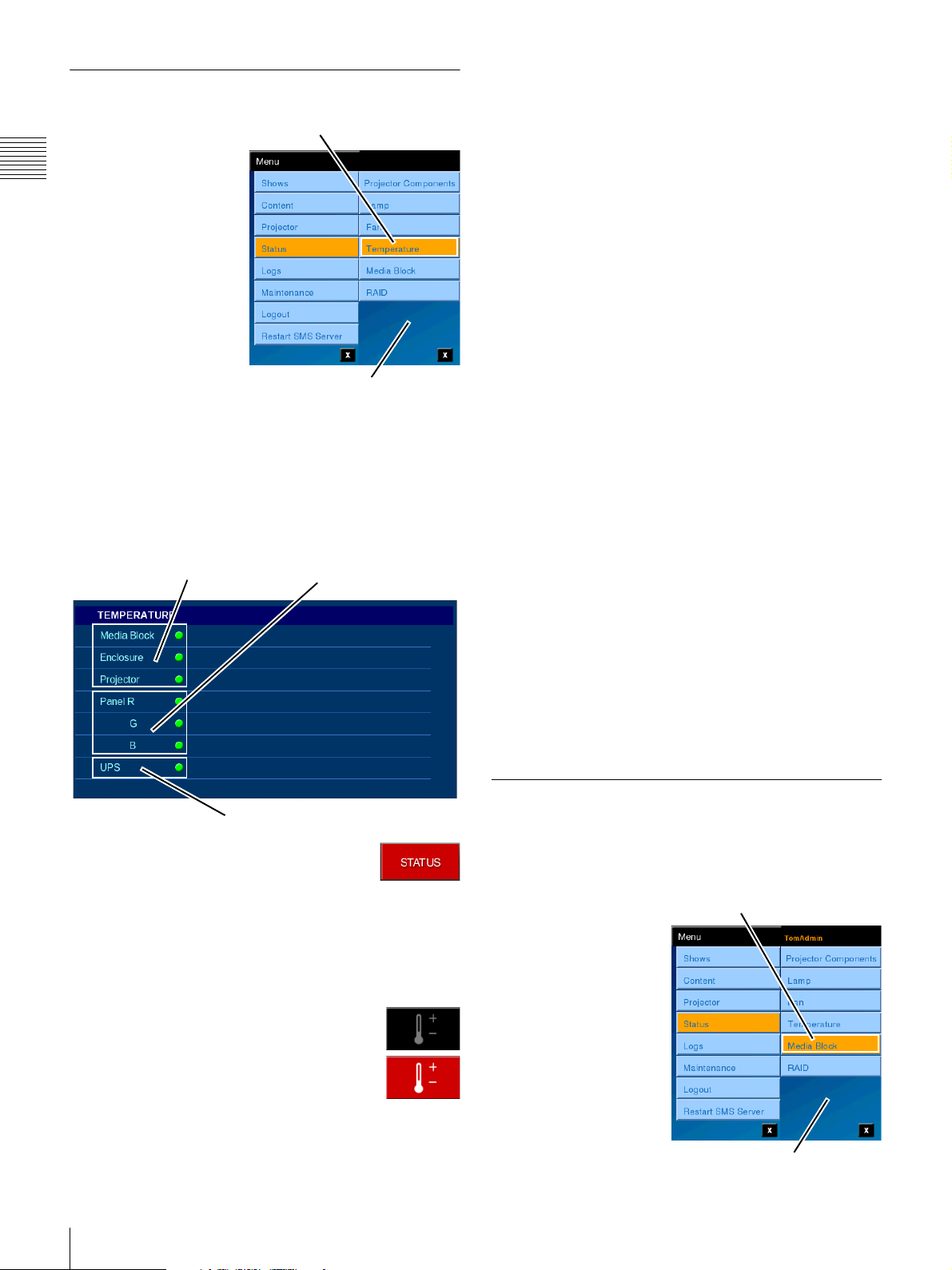
Temperature Status
To access the
Temperature Status
pane, tap Menu, tap
Chapter 1 User Guide
Status and then tap
Temperature.
The Temperature pane
appears which displays
status indicators for
temperatures in
Auditorium Unit
subsystems and areas in
the Projector sub-system.
They are:
•Media Block,
Enclosure, Projector
• Peltier (R, G, B)
•UPS
When Temperature Status is selected from the Status
Menu the TEMPERATURE status information is
displayed.
Media Block
Enclosure
Projector
Tap Temperature
Status Menu
Peltier Devices
Red, Green, Blue
Subsystem Temperature
Three major areas in the Auditorium Unit are monitored
for operational temperatures. They are; the Media Block,
the Auditorium Unit Enclosure, and the Projector.
Media Block
The Media Block indicator is green when the unit
temperature is within operating limits. The indicator will
display red when an error is detected.
Enclosure
The Enclosure (Auditorium Unit) contains two thermistors
monitoring temperatures. One is located in the Lower
(base) area and the other is located in the Upper area. Both
thermistors are monitored and their status is shown on the
Enclosure indicator. The indicator will display red when
an error is detected.
Projector
A number of areas in the Projector have temperature
sensors dedicated to monitoring operating temperatures on
critical devices.
UPS
The Uninterruptable Power Supply (UPS) self monitors
for internal temperature. The indicator is green when the
unit temperature is within operating limits. The indicator
will display red when an error is detected.
UPS
The STATUS button shown to the right
appears on all SMS Controller windows and
provides immediate access to the
Temperature Status information. When any Warning
condition exists the STATUS button will appear RED as
shown. To view which projector area requires attention,
tap the STATUS button and the Status Selector/Warning
buttons appear.
As illustrated to the right, the Temperature
Selector/Warning indicator will be RED
when an error condition exists. To view the
Temperature Status, tap the Temperature
Warning icon.
Projector Component Temperatures
Panel (R, G, B Imaging)
Maintaining correct operating temperature on the imaging
panels is critical to the quality of presentation. The
indicator will display red when a Panel temperature error
is detected.
Media Block Status
Because of the critical nature of the Media Block to the
management and presentation of content, a number of its
internal operations are monitored.
To access the Status pane
for the Media Block, tap
Menu, tap Status and
then tap Media Block.
The MEDIA BLOCK
pane appears which
displays status indicators
for the current state of the
Media Block.
•READY
•PLAY
•ALARM
Tap Media Block
Status Menu
56
Status
Page 57
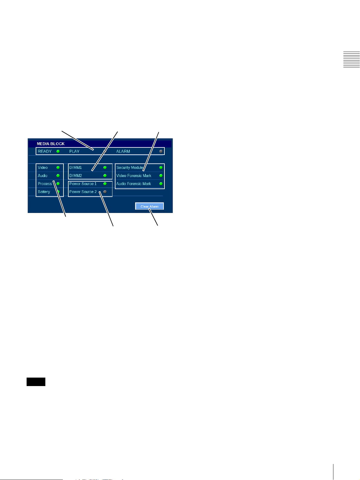
Also, the status of various operational areas within the unit
are indicated. Those areas are:
• Process/Component
Video, Audio, Process, and Battery
•Memory
DIMM 1 and DIMM 2
• Power Supplies
Power Source 1 and Power Source 2
• Security
Security Module and Forensic Mark
Process/Component
Included in the MEDIA BLOCK System group are three
indicators:
•Video
Indicates the status or health of the video signal
processing.
•Audio
Indicates the status or health of the audio signal
processing.
Chapter 1 User Guide
When Media Block is selected from the Status Menu the
MEDIA BLOCK information is displayed.
Media Block State
Process/Component
Memory
Power Supplies
Security
Clear
Alarm
Media Block State
The State indicator for the Media Block are as follows:
• READY
When illuminated (GREEN), indicates the Media
Block is operational.
•PLAY
When illuminated (GREEN), indicates the Media
Block is currently in PLAY mode.
• Process
Indicates the status or health of the signal
(image/sound essence) processing.
• Battery
Indicates the status or health of the internal batteries
that provides power to sustain Media Block settings.
Memory
•DIMM 1
Indicates the status or health of the #1 Dual Inline
Memory Module (DIMM) installed in the Media
Block.
•DIMM 2
Indicates the status or health of the #2 Dual Inline
Memory Module (DIMM) installed in the Media
Block.
Power Supplies
Two Power Sources can be present in the Media Block.
• Power Source 1
Indicates the status or health of the #1 Power Supply
installed in the Media Block.
• Power Source 2
Indicates the status or health of the #2 Power Supply
installed in the Media Block.
2
1
• ALARM
When illuminated (RED), indicates there is a
problem with the Media Block operation. If during,
the start up process the RAID encounters a problem,
this indicator will be illuminated.
To clear the Alarm indication, tap Clear Alarm.
Note
Currently, the Media Block can be either Playing, i.e.,
decoding and sending Content Elements to the projector,
or it can be Ingesting.
1.Located in the Media Block fan units.
2.The presence of a 2nd Power Supply in the Media Block
is optional.
Status
57
Page 58
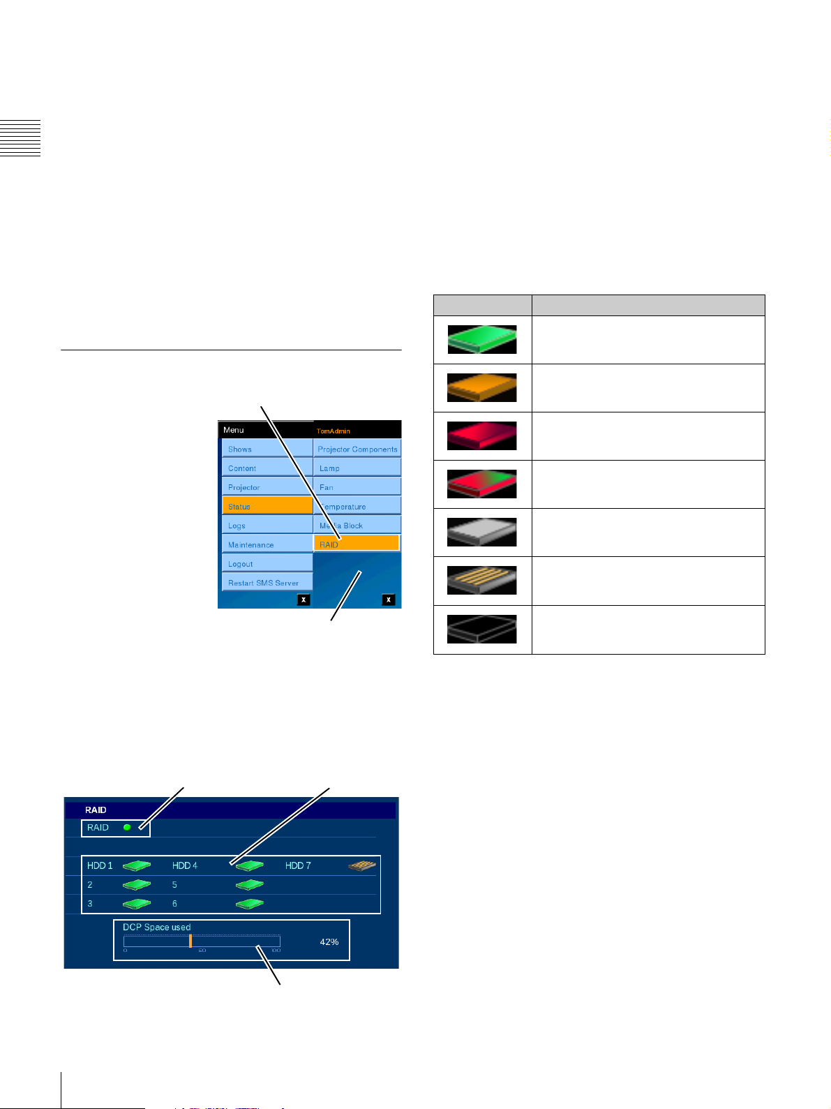
Security
Two security areas are monitored. One area deals with
security of the enclosure and control of the decrypting
process. The second area deals with processing of the
decrypted content and insertion of a forensic mark into the
Chapter 1 User Guide
video picture which can be used to trace the source of
pirate content taken with a video camera from the screen
presentation.
• Security
Indicates the status or health of the Media Block
security system and content key processing.
• Video/Audio Forensic Mark
Indicates the status or health of the Forensic
Marking processing.
RAID Status
A single indicator provides consolidated status
information for the RAID in the Media Block.
HDD Status
The icons of individual HDD indicate the status of the
specific Hard Disk Drive. HDD are numbered 1 to 7 which
corresponds to their location in the Media Block. Six
HDDs operate as a RAID device with a 7th Drive acting as
a spare.
The HDD Status/State information is shown in the
following table.
Appearance HDD Status/State
Green - HDD is Installed and operating
normally.
RAID Status
The Sony Screen
Management System
includes the Sony
LMT-300 Media Block
where the RAID storage
system is an integral part
of the Media Block.
The high level of
integration in the
LMT-300 allows for
closer monitoring of the
RAID storage. To view
RAID status, tap Menu,
tap Status and then tap
RAID. The RAID pane
appears containing Status indicators (icons) for the RAID
Storage and the individual Hard Disk Drives (HDD) in the
RAID appears.
On the RAID pane, a consolidated status indicator for the
RAID is shown along with individual icons indicating the
status of each individual HDD.
Tap RAID
Status Menu
Yellow - HDD is installed but is in a
Warning state.
Red - HDD is installed but is in an Error
condition.
Red/Green - HDD is installed and is in
the process of being rebuilt.
White/Gray - HDD is installed and is
designated as a Spare Drive.
Yellow/Gray - HDD is installed but is in
an unusable state. Replace with a new
HDD.
Outline - HDD is not installed in this
position. The Drive icon appears as a
simple outline.
DCP Space Used
Shows a graphical representation of how many percent of
the storage space allocated to DCP Storage are in use.
58
Status
RAID Status
HDD Status
DCP Space Used
Page 59
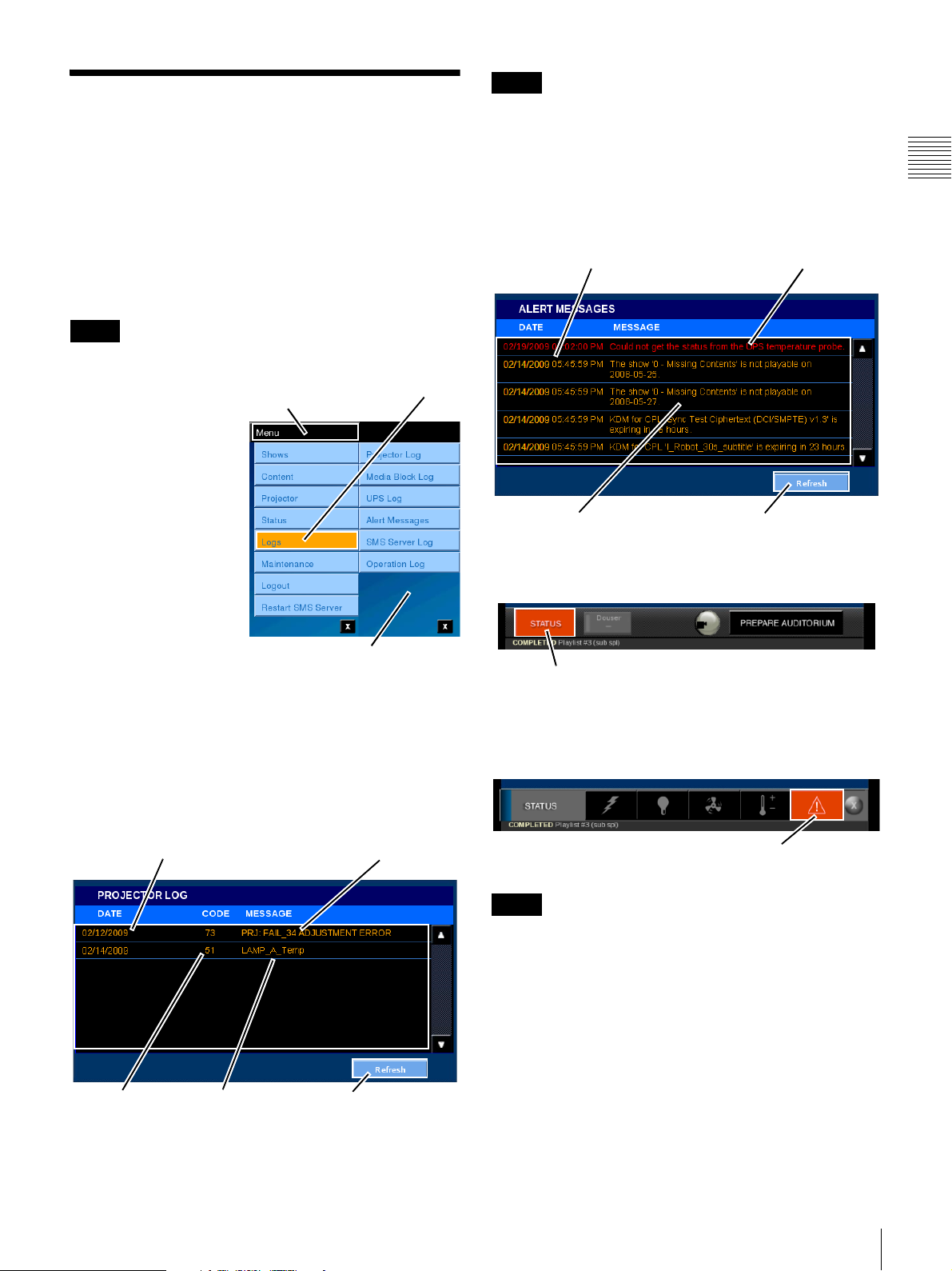
Logs
The Screen Management System maintains logs for
selected devices and operations. These logs are used to
track subsystem errors or, in the case of the Operations
Log, to track system operations and specific operator
actions. When reporting issues to product support, make
sure that you include the date/time, complete error
message, the code and the color of the indicator (if
present).
Note
Access to specific logs is Role restricted.
Note
The SMS communicates every 10 seconds with the
projector and records the status. Touching Refresh reads
the latest status information.
The Alert Message Log and SMS Server Log are primarily
textual in nature with an extended Date and, when
appropriate, Time stamp and a more detailed Message as
shown below.
Logged EventsDate/Time of Events
Chapter 1 User Guide
The Logs menu selection
allows you to view the
Tap Menu
Tap Logs
following Logs for the
system.
• Projector Log
• Media Block Log
•UPS Log
1
• Alert Messages
• SMS Server Log
• Operation Log
Logs are stored in a
specific folder on the
SMS Server and may be
copied to the SMS
Logs Menu
Controller PC. Refer to
the SMS Controller User’s Guide for additional
information.
To view a specific log, tap Menu, tap Logs, and then tap
the Log (Name) for the item of interest. Logs for the
Projector, Media Block and UPS include an Error Code
and a brief Message. An example of this type of log is
shown below.
Logged EventsDate of Events
Alert Messages
Refresh
When the STATUS button is lit in red, the Alert Message
contains log information.
STATUS Alert
To display the Alert Message, tap STATUS and then tap
the Message Alert icon. The ALERT MESSAGES pane
opens, and the Alert Message is shown.
Message Alert Icon
Error Codes Error Messages
1.Present when the Auditorium Units has an integral UPS.
Refresh
Note
Note the lack of an Error Code in the Alert Message Log
and SMS Server Log.
The Operations Log deals with operational events of the
system. This log is also textual in nature with an extended
Date/Time stamp, an identification of the Logged In User,
and a detailed Message as shown below.
Logs
59
Page 60
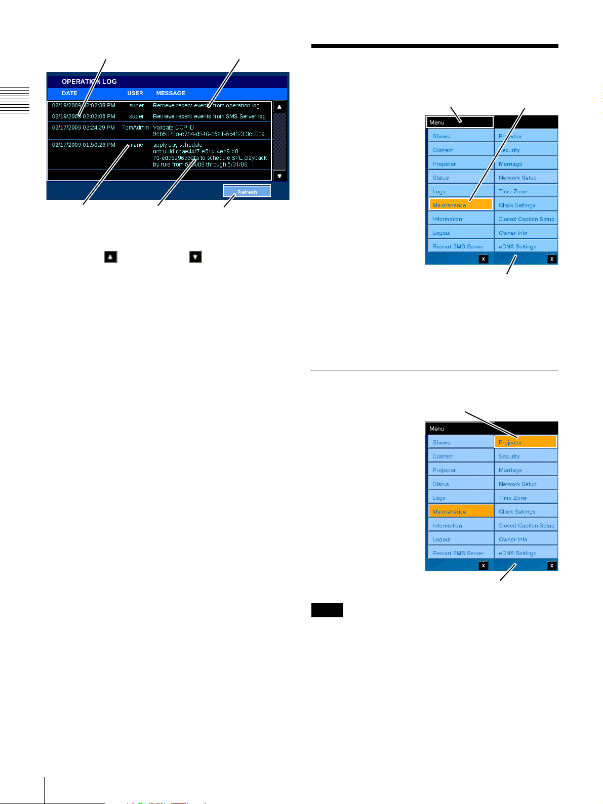
Logged EventsDate/Time of Events
Maintenance
Chapter 1 User Guide
MessagesLogged In User
Refresh
Log Events are ordered with the latest at the top of the list.
tap Scroll Up or Scroll Down the locate the Event
of interest.
Tap Refresh to insure that the latest information is
displayed.
The Maintenance menu
Tap Men u Tap Maintenance
selection allows you to
access the following
maintenance functions
for the SMS System.
• Marriage
• Network Setup
•Time Zone
• Clock Settings
• Closed Caption
Setup
•Owner Info
• eCNA Settings
General Maintenance
operations include;
Projector specific settings, System Security information,
and Theater Network settings
Maintenance Menu
1
.
Additional information may be contained in
documentation specific to the sub-system.
Projector
To access the
Tap Projector
Maintenance - Projector
pane, tap Menu, tap
Maintenance and then
tap Projector. The
Projector Maintenance
pane appears which
allows the you to Refresh
the Projector data, select
a Test Pattern to be
shown on the screen, and
initiate the Luminance
calibration process. In
addition, the current
Lamp Information is
shown.
Note
Some projector setup and maintenance operations use the
SRX Controller
1.The Auditorium Unit has an internal network that has a
fixed configuration. The settings available on the Network
Setup pane are for Theater Network connection.
2
application. An example would be; Lamp
Maintenance Menu
60
2.The SRX Controller exercises direct control over the
projector and therefore should not be used at the same time
the Projectionist Terminal or SMS Controller is in
operation.
Maintenance
Page 61
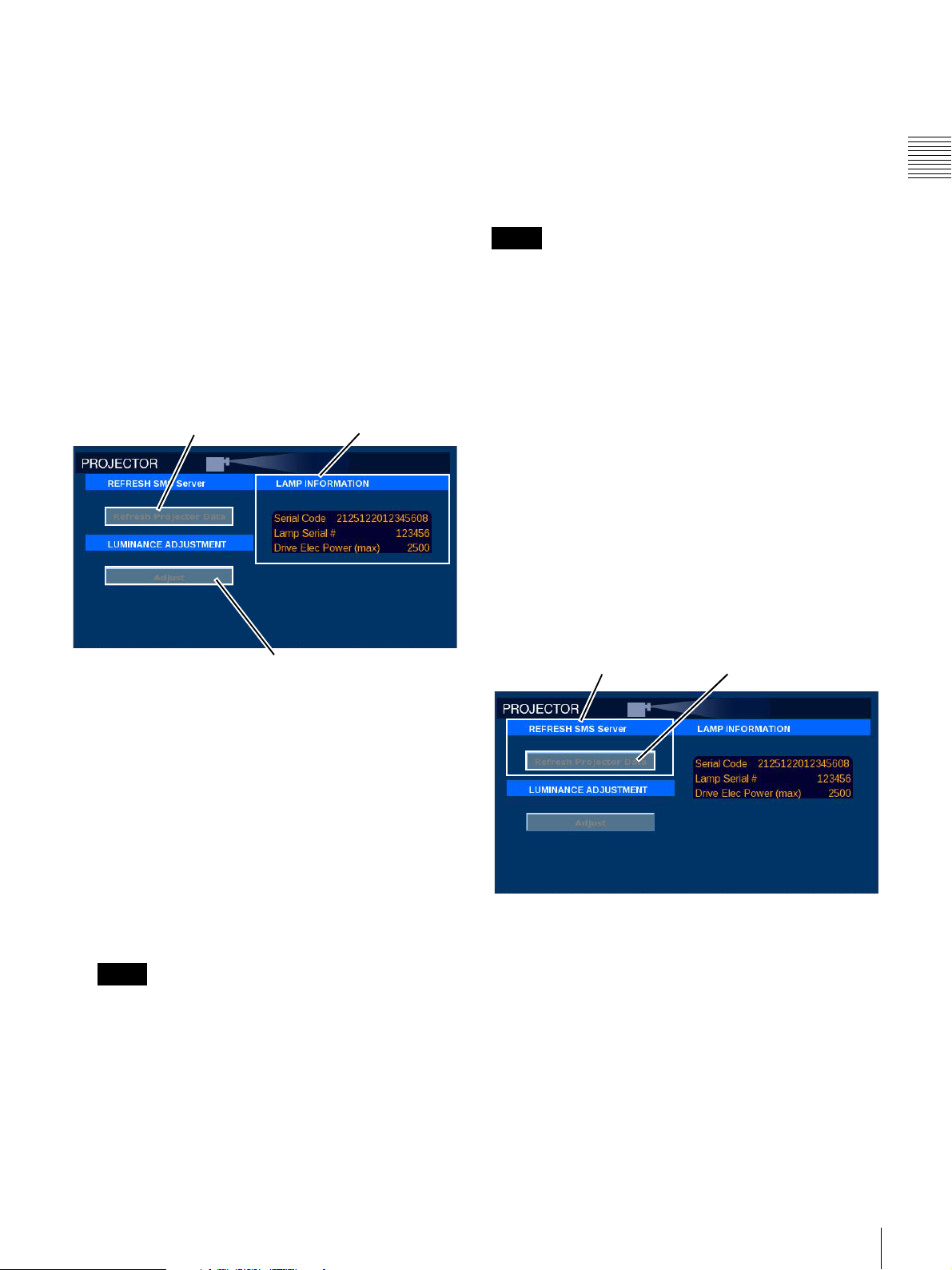
Replacement, setting of FUNCTION names, and
associating a specific Color Space with a FUNCTION.
The SRX Controller is a stand alone software application
that allows a computer to directly control the SRX-R320.
This control is via the serial connector located on the rear
panel of the projector just below the circuit breakers. When
adjustments are made using the SRX Controller the
changes and settings are not automatically transferred to
the SMS Server and therefore, do not appear on the
Projectionist Terminal. A REFRESH button is available
on the PROJECTOR MAINTENANCE pane which
causes the SMS Server to query the Projector and make the
refreshed data available to the Projectionist Terminal.
Executing the Calibrate Luminance function should be
done with care as this can affect the Lamp Power range and
cause the brightness of the image to change. Selecting a
Test Pattern will interrupt the presentation image.
Refresh Projector Data LAMP INFORMATION
• LAMP INFORMATION
Displays the Serial Code, Lamp Serial Number and the
maximum rated Lamp Power.
• LUMINANCE ADJUSTMENT
– Adjust (Luminance Calibration)
Allows you to calibrate the Luminance vs. Lamp
Power table data stored in the projector.
Note
This function is only available when the Lamp Control
Mode of the projector is set to “Luminance”. Because the
default Lamp Control Mode setting is “Lamp Power”, the
function should normally not be used. The SRC Controller
application can be used to set the projector to the
Luminance mode.
Refresh SMS Server
In the REFRESH SMS Server group you can manually
force the SMS Server application to refresh the SMS
Server with Projector stored data.
Normally the SMS Server is the device controlling the
Projector and saves any changes made by the SMS Server
to the Projector as they are made. However, if a projector
setting was changed with the SRC Controller, this will not
be detected by the SMS Server. If the SRX Controller was
used for maintenance purposes or similar, and any change
was made to the projector settings, the SMS Server data
must be refreshed manually.
Chapter 1 User Guide
Calibrate Luminance
Operations available on the Maintenance screen are;
• REFRESH SMS Server
The Refresh Projector Data button reloads the SMS
Server application with all the Projector data.
The Refresh function is used whenever the SRX
Controller
1
has been connected directly to the
projector to accomplish maintenance operations,
e.g., bulb replacement. After the SRX Controller has
been disconnected from the projector you should
refresh the SMS Server (tap Refresh Projector Data)
which will update the SMS Server with any changes
made using the SRX Controller application.
Note
Refresh Projector Data is a maintenance function.
Refreshing the SMS Server with new data from the
projector takes some time and may result in
unexpected projector operation should this action be
taken during Show presentation.
1.The SRX Controller is typically a PC running the SRX
Controller application and connected to the projector
using a serial data line.
REFRESH SMS Server
Refresh Projector Data
To refresh the Projector Data, tap Menu, tap
Maintenance, tap Projector, and then tap Refresh
Projector Data in the REFRESH SMS Server group.
Maintenance
61
Page 62
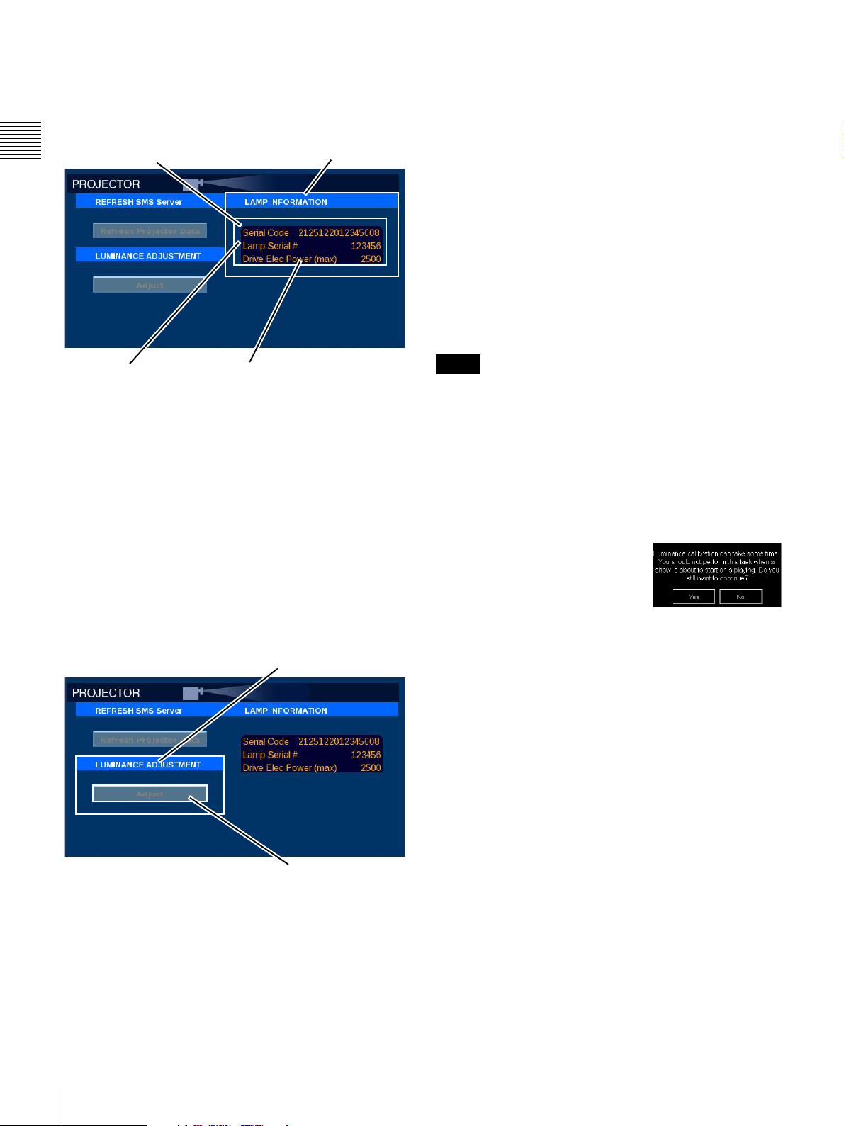
Lamp Information
Every lamp is identified by a unique 16 digit Serial Code
that includes the manufacturer id, lamp power (min./max.
range), and the individual lamp serial number.
Chapter 1 User Guide
Lamp Serial Code
LAMP INFORMATION
Adjust (Luminance Calibration)
The SRX-R320 Projector includes a Lamp Control Mode
feature which, when enabled
1
using the SRX Control
application, maintains a nearly constant screen luminance
as the lamp ages and the bulb brightness vs. lamp power
applied is reduced. During the lamp replacement
procedure, lamp positioning is optimized. In addition, a
lamp brightness (luminance) vs. Lamp Power table is
created.
The Luminance Adjustment process uses an internal photo
sensor which measures the lamp’s brightness while
adjusting the Lamp Power across the Lamp Power range
(50~100) as indicated in the lamp’s Serial Code. A
brightness vs. lamp power table is created. This table is
used as a reference (for adjusting lamp power) to maintain
the lamp brightness value stored in the FUNCTION.
Lamp Serial No.
Drive Elec Power (max)
The Serial Number of the currently installed Lamp and the
Drive Elec. Power (max) is shown in LAMP
INFORMATION. A new Lamp Serial Code is entered
during the Lamp replacement process using the SRX
Controller application or the Installer screen (Role
restricted). When the Serial Code of the new lamp has been
entered, the accumulated lamp usage time is automatically
reset to “0”, and the count will restart from the replacement
point. The replacement date is also set (see “Lamp Status”
on page 54).
Luminance Adjustment
Projector maintenance may require the re-calibration of
Luminance.
LUMINANCE ADJUSTEMENT
Note
The Luminance Adjustment process takes some time to
complete and should not be undertaken without an
understanding of the process. Normally it is done when the
lamp is replaced and periodically to insure correct tracking
of lamp brightness, i.e., screen luminance, vs. lamp power.
Essentially, the process steps the Lamp Power from the
minimum bulb rated setting to the maximum bulb rated
setting and measures the photocell detected brightness.
The results are saved in a table located in the Projector.
To initiate the Luminance
Adjustment process, tap Menu,
tap Maintenance, tap Projector,
and then tap Adjust in the
Luminance Adjustment group. A
confirmation message appears. Tap YES to continue or tap
NO to abandon the process.
Luminance calibration has only a relative impact on the
actual screen luminance based on the value stored in a
FUNCTION. This stored value is returned by the photocell
sampling the bulb brightness to realize the desired value,
e.g., 14ft-L, and stored in a specific labelled FUNCTION
such as “CinemaScope® 14ft-L”. The Luminance
Adjustment process is done to insure that a brightness vs.
Lamp Power relationship is known to the Projector
subsystem.
62
Adjust
1.This function is only available when the Lamp Control
Mode of the projector is set to “Luminance”. Because the
default Lamp Control Mode setting is “Lamp Power”, take
care when attempting to use the function. The SRC
Controller application can be used to set the projector to
the Luminance mode.
Maintenance
Page 63
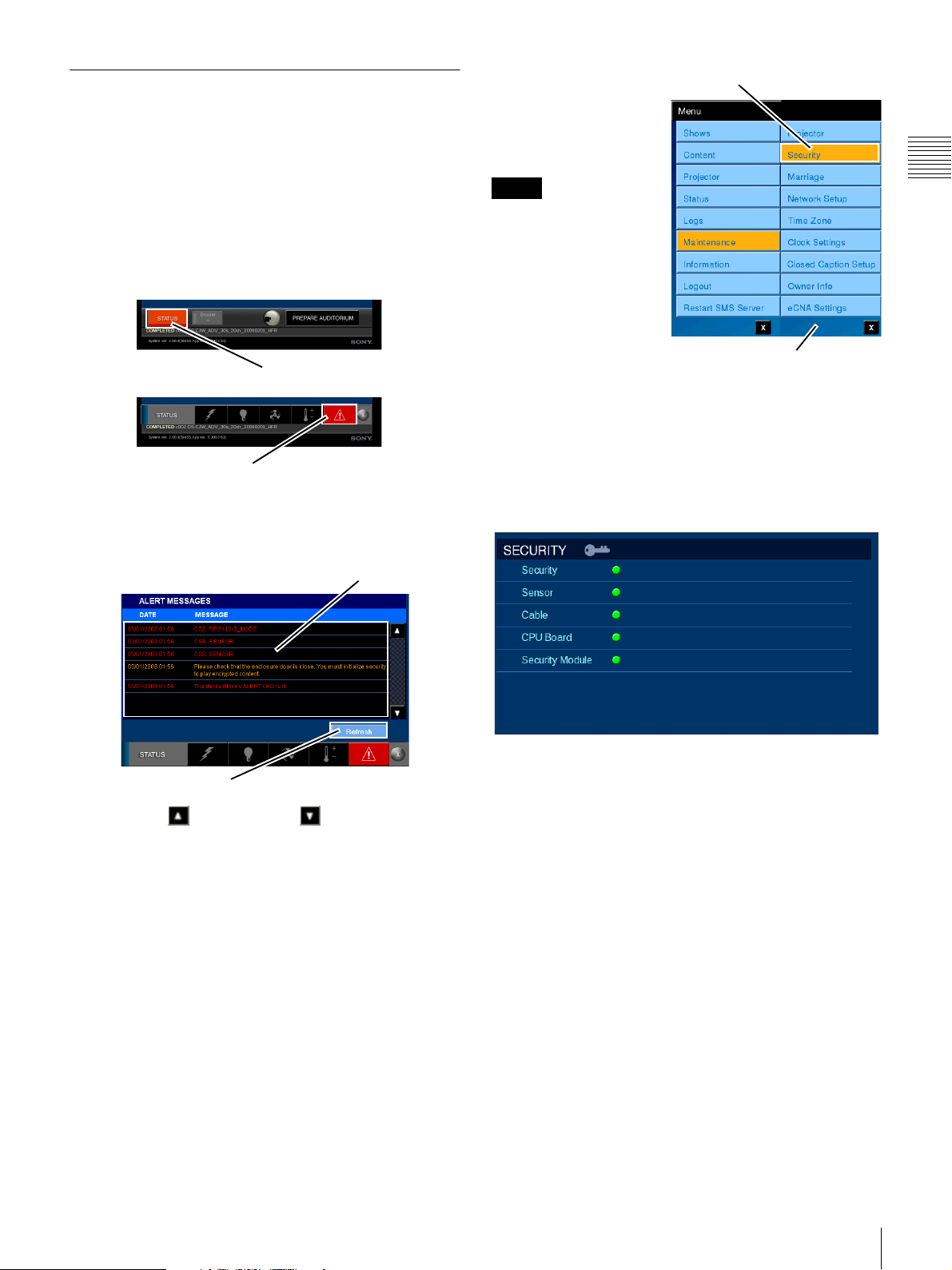
Security (Role Restricted)
System Security is designed to protect the DCP Packages
from unauthorized access to content and any potential for
duplication in an unencoded form. When the security of
the Auditorium Unit has been breached or a tamper switch
failure is detected, presentation is halted and cannot be
resumed until Security has been initialized. In addition, the
STATUS Alert is set RED, the MESSAGE Alert is set
RED, and a Security Alert Message is generated and
written to the Alert Message Log.
STATUS Alert
Message Alert Icon
To view the Alert Message, tap STATUS and then tap the
MESSAGE Alert icon. The ALERT MESSAGES pane
appears and is shown below.
ALERT MESSAGE List
To access the Security
Tap S e c u rity
pane, tap Menu, tap
Maintenance and then
tap Security. The
Security pane appears.
Note
It may take some minutes
for the Security Services
to come to a ready state
following initial
application or restoration
of system power.
When the Auditorium
Unit’s CSS (Cavity
Maintenance Menu
Security System) has
been breached the Security indicator is illuminated. While
all users can view the Security pane (illustrated below), the
ability to initialize the system security
1
is restricted to an
authorized user. This is done to insure that only
responsible persons can access the interior of the
Auditorium Unit and then resume the Content Element
decrypting and presentation process.
Chapter 1 User Guide
Refresh
Tap Scroll Up or Scroll Down the locate the ALert
Message of interest. To insure that the latest Alert
Messages are present in the list, tap Refresh.
1.Confirm the state where no unauthorized acquisition of
content or other modification was made before initializing.
Maintenance
63
Page 64
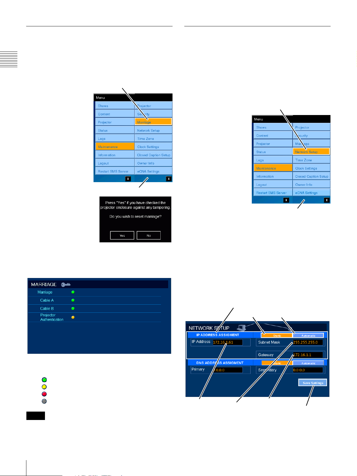
Marriage
Network Setup (Theater)
Performs Marriage processes between the Media Block
and Projector according to DCI requirements.
To access MARRIAGE, tap Menu, tap Maintenance and
Chapter 1 User Guide
then tap Marriage.
Before performing
Tap Marriage
Marriage, synchronize
Media Block with the
SMS Server clock. See
“Clock Settings” on
page 67 for additional
information.
To perform Marriage,
you must log in with the
proper function
restriction role.
Maintenance Menu
After performing
Marriage, always initialize
CSS Security. See the
previous section for
additional information.
The MARRIAGE pane appears.
In this pane, you can check the Marriage status between
the Media Block and the Projector.
The Auditorium Unit’s configuration for connecting to the
Theater Network is via a dedicated network connection on
the SMS Server. Configuration of this connection is
realized using the Network Setup screen on the
Projectionist Terminal.
Settings available on the Network Setup screen apply to
the SMS Server’s Theater Network connection only.
Typically, the Screen
Tap Network Setup
Management System
Controller is connected
to the Theater Network.
If the Theater Network
settings are incorrect
then access to the
Auditorium Unit from
the Screen Management
System Controller is not
possible.
To access Network
Setup, tap Menu, tap
Maintenance, and then
tap Network Setup. The
Maintenance Menu
Network Setup screen
appears
Two groups appear on the Network Setup screen. They
are; IP ADDRESS ASSIGNMENT and DNS ADDRESS
ASSIGNMENT.
Network Address Assignment
The IP ADDRESS ASSIGNMENT group includes
settings for the SMS Server’s IP address, it’s Subnet Mask,
and, when needed, the IP address of the Gateway between
the Auditorium Unit and the Theater Network.
IP ADDRESS ASSIGNMENT
Static
Automatic
The MARRIAGE pane uses the following status
indicators.
(Green) - Safety is assured.
(Yellow) - Not connected.
(Red) - Safety is not assured.
(Gray) - Status cannot be ascertained.
Note
For software version 2.20 and later, Marriage will be
disconnected also when the enclosure is opened.
64
Maintenance
IP Address
Subnet Mask
Gateway
Save
Settings
Address assignments can be either Static or Automatic (if DHCP
is in use). The above illustration shows a Static configuration.
Page 65
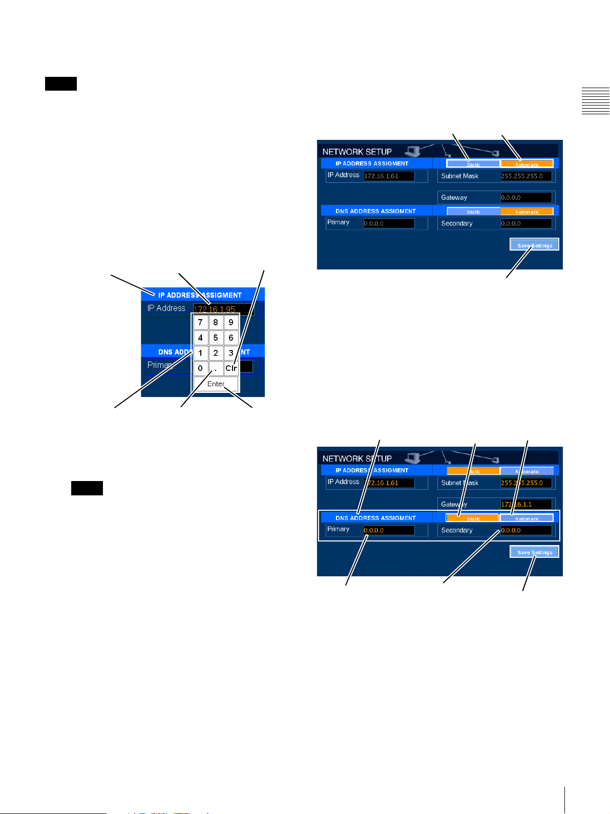
The screen appearance for a Automatic configuration is
illustrated in
Note
“Automatic Network IP address”
.
In the Network Setup illustrations, Static IP addressing has
been selected.
Set Static Network IP address
A static (or predetermined) IP address can be assigned to
the SMS Server’s Theater Network connection. To set the
Static IP address option, tap STATIC in the IP ADDRESS
ASSIGNMENT group and enter the values for IP Address,
Subnet Mask and Gateway.
• IP Address
To set a static IP address, tap IP Address and the
Enter Address popup appears.
Automatic Network IP address
To set the Automatic IP address option, tap
AUTOMATIC in the IP ADDRESS ASSIGNMENT
group and then tap Save Settings. The appropriate value
for IP Address, Subnet Mask and Gateway are assigned by
the DHCP server.
Static Automatic
Chapter 1 User Guide
IP ADDRESS
Assignment
Keypad
Current
IP address
“dot”
CLEAR
Enter
To set a new IP address, tap CLEAR, set the new IP
address by tapping the numbers on the Keypad, and
then tap Accept.
Note
Entering the IP addresses from the ENTER
ADDRESS popup uses the “dotted decimal” format
and must include the “dot(s)” as part of the entry.
• Subnet Mask
To set a static Subnet Mask, tap Subnet Mask and
the ENTER ADDRESS popup appears. Tap
CLEAR, set the new IP address by tapping the
numbers on the Keypad, and then tap Accept.
•Gateway
To set a static Gateway, tap Gateway and the
ENTER ADDRESS popup appears. Tap CLEAR,
set the new IP address by tapping the numbers on the
Keypad, and then tap Accept.
(Clr)
Save Settings
Before closing this screen, you must tap the Save Settings
button to send the changed settings to the SMS Server. If
you move to another screen without tapping the Save
Settings button, all changes will be lost.
DNS Address Assignment
The DNS ADDRESS ASSIGNMENT group includes
settings for the Primary and Secondary Domain Name
System (DNS) Servers supporting the Theater Network
DNS ADDRESS ASSIGNMENT
Primary address
Secondary address
Static
Automatic
Save
Settings
If your Theater Network is isolated from the Internet then
there is no need for DNS Address assignments and they
can be 0.0.0.0 (as shown). However, any planned access to
the Internet, even if that access is via a firewall or
corporate network will require DNS Addresses be set.
Address assignments can be either Static or Automatic (if
DHCP is in use). Consult with your network administrator
for additional information about DNS settings.
1
.
1.The Domain Name System (DNS) associates IP
addresses with domain names.
Maintenance
65
Page 66
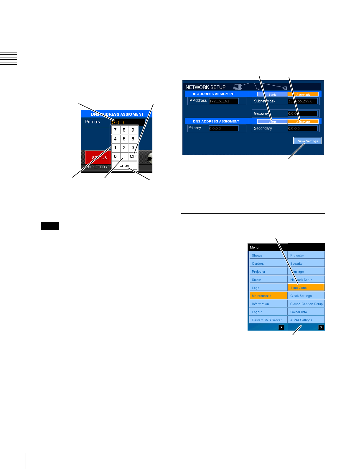
Set Static DNS address
A static (or predetermined) DNS address can be assigned
to the SMS Server’s Theater Network connection. To set
the Static DNS address option, tap STATIC in the DNS
ADDRESS ASSIGNMENT group and enter the IP address
values for Primary and Secondary DNS servers.
Chapter 1 User Guide
• Primary (IP address)
To set the Primary DNS Server static IP address, tap
Primary and the Enter Address popup appears.
Automatic DNS IP address
To set the Automatic IP address option, tap
AUTOMATIC in the IP ADDRESS ASSIGNMENT
group and then tap Save Settings. The appropriate value
for the Primary DNS IP address and Secondary DNS
Server IP address are obtained from the DHCP server.
Static Automatic
Current DNS IP address
Keypad
“dot”
CLEAR
Enter
To set a new DNS Server IP address, tap CLEAR,
set the new address by tapping the numbers on the
Keypad, and then tap Accept.
Note
Entering the DNS Server IP address from the
ENTER ADDRESS popup uses the “dotted
decimal” format and must include the “dot(s)” as
part of the entry.
• Secondary (IP address)
To set the Secondary DNS Server static IP address,
tap Secondary and the Enter Address popup
appears. To set a new DNS Server IP address, tap
CLEAR, set the new address by tapping the
numbers on the Keypad, and then tap Accept.
Save Settings
Before closing this screen, you must tap the Save Settings
button to send the changed settings to the SMS Server. If
you move to another screen without tapping the Save
Settings button, all changes will be lost.
Time Zone
The Time Zone Settings
are used to convert the
date/time stamps applied
to the various logs to a
value appropriate to the
time zone where the
system is located.
Internally, the system
uses UTC for all
operations.
To access Time Zone
Settings, tap Menu, tap
Maintenance, and then
tap Time Zone. The
Time Zone Settings
screen appears
Tap Time Zone
Maintenance Menu
66
To set the local time zone, scroll the Time Zone list until
your local time zone is visible and then select the Zone.
Daylight Savings Time (Summer Time) may or may not be
applicable for your location. If it is not applicable, select
the Disable daylight savings time option and then click
Save Settings.
After changing the Time Zone, tap Menu, Restart SMS
Server, Shutdown in sequence to shut down the SMS
Server. (This will also shut down the Media Block, and
cause the projector to switch to STANDBY mode.)
Maintenance
Page 67
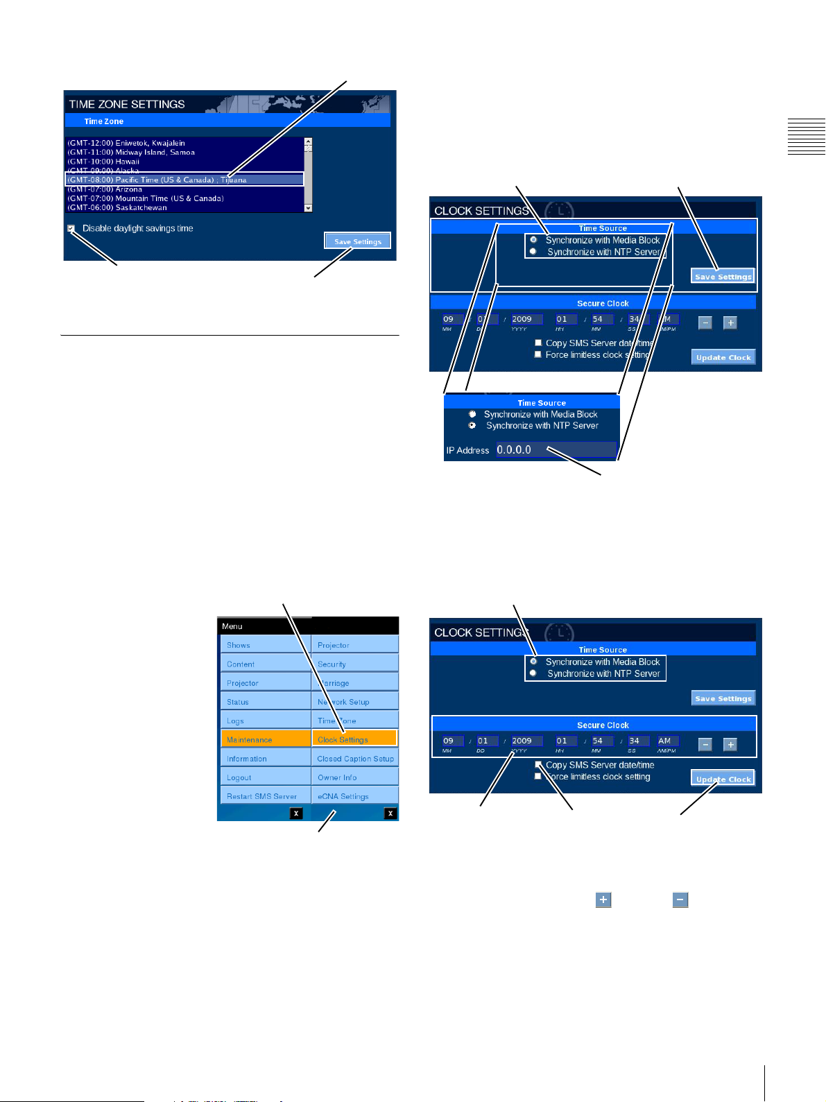
Time Zone
box appears where you enter the NTP source. Tap the IP
Address box and, using the on-screen keyboard, enter the
IP address of the target NTP Server and then tap Save
Settings. When Synchronize with Media Block is selected
the IP Address box is not present.When the Time Source
has been set, tap Save Settings.
Save SettingsMedia Block Time Source
Chapter 1 User Guide
Disable Daylight
Savings Time
Save
Settings
Clock Settings (Role Restricted)
Each Auditorium Unit contains a secure System Clock
which is integral to the Media Block. This clock is used to
determine whether a Content associated KDM is valid for
the date and time of Content presentation. The clock can be
referenced to an established Network Time Server or it can
be operated in a standalone configuration. In a standalone
configuration, regular adjustment will be needed. Because
the time value of the secure System Clock is directly related
to the ability to realize Content presentation, access to the
Clock Settings menu and functions associated with setting
the clock reference or adjusting its value are restricted to
trusted users.
Setting the Time Source
(Reference) for the SMS
Server is realized from
the Clock Settings
screen. When you are a
“trusted” user an
additional menu
selection appears when
you access the
Maintenance menu.
Tap Clock Settings
NTP Time Source
If you select Synchronize with Media Block the secure
Clock in the Media Block operates in a standalone mode.
The lower portion of the Clock Settings pane includes the
ability to adjust the secure System Clock in the Media Block.
Media Block Time Source
To access the Time
Source setting, tap
Menu, tap
Maintenance, and then
tap Clock Settings. The
Maintenance Menu
CLOCK SETTINGS
screen appears.
The CLOCK SETTINGS screen is divided into two areas
Time Settings (SMS Server internal clock) and Secure
Clock (Media Bock clock).
To set the reference source for SMS Server time
synchronization select either the Synchronize with Media
Block or Synchronize with NTP Server option. When
you select Synchronize with NTP Server the IP Address
Clock Settings
Copy from
SMS Server
Update Clock
To adjust the Secure Clock, select the value you wish to
adjust, e.g., tap HH, MM, SS. The value is selected and
then tap the appropriate Plus or Minus button to set
the desired value
1.The maximum change is plus or minus 6 minutes per
year.
1
.
Maintenance
67
Page 68
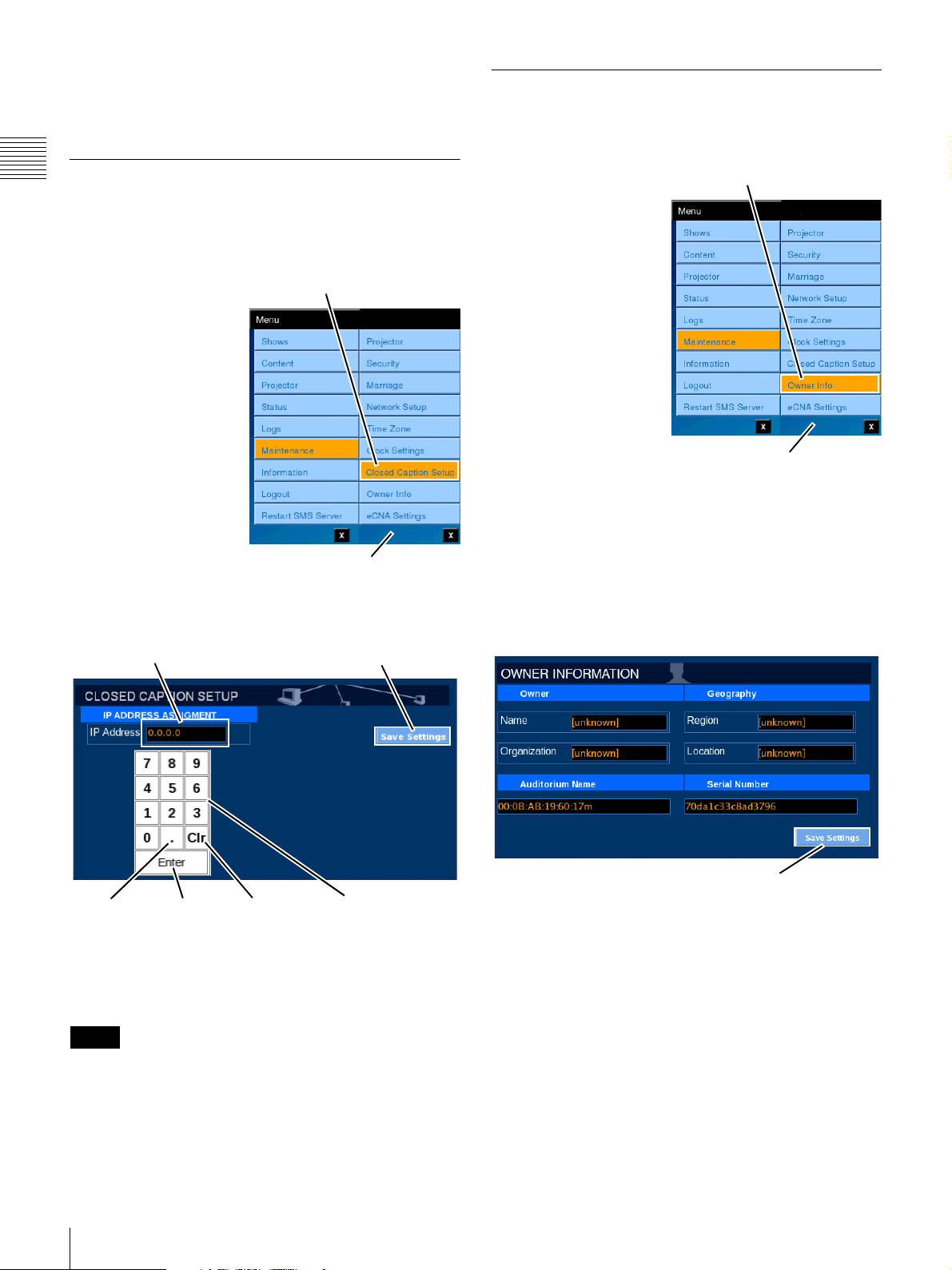
A Manufacturer Password is needed to use the “Force
limitless clock setting” option. Only the Manufacturer can
obtain a Manufacturer Password.
Owner Information (Role Restricted)
The Auditorium Unit can be identified by setting the
“Owner Information” in the Projector.
Closed Caption Setup
Chapter 1 User Guide
The Closed Caption Setup lets you specify the IP address
of a closed caption decoder located on an external network
of the SMS Server.
To access the CLOSED
Tap Closed Caption Setup
CAPTION SETUP pane,
tap Menu, Maintenance,
Closed Caption Setup in
sequence. The CLOSED
CAPTION SETUP pane
appears.
Maintenance Menu
To specify the IP address, tap the IP Address field.
The Enter Address popup window appears.
Save SettingsIP Adress
To access Owner
Tap Owner Info
Information, tap Menu,
tap Maintenance, and
then tap Owner Info.
The Owner Information
screen appears.
The Owner Information
screen contains
information relating to;
the name of the Owner
(Exhibitor or Company),
the Geographical area,
the Auditorium Name
(ID), and the Serial
Number of the Projector.
Maintenance Menu
The Projector Serial
Number is automatically
filled by information returned by the projector.
To enter new values in the available boxes, tap the
appropriate box and the on-screen keyboard appears.
Using the on-screen keyboard enter the information and
the tap ENTER on the on-screen keyboard. The new value
appears in the associated text box. When all changes have
been made, tap Save Settings.
“dot”
Enter Clr Keypad
To enter a new IP address, tap Clr to clear the current entry,
and then set the new address by tapping the numbers on the
Keypad. When you tap Enter, the new IP address value is
set. When the input is complete, tap Save Settings.
Note
When entering an IP address in the Enter Address popup
window, be sure to also enter the separator dots (.).
68
Maintenance
Save Settings
• Auditorium Name - The default value for
Auditorium Name is the MAC value for the
projector subsystem’s Network Interface Card. This
value may be changed
1
to reflect a name more
appropriate to the Exhibitor’s facility.
• Serial Number - The Serial Number value is read
from the projector subsystem. This value is set
during the projector’s manufacturing process and
cannot be changed.
1.Changing the Auditorium Name does not effect the
MAC address for the projector subsystem.
Page 69
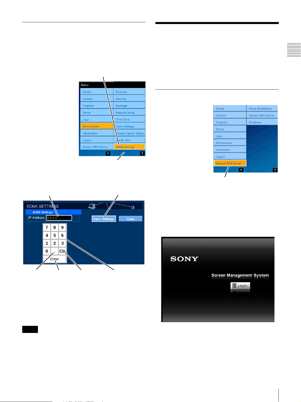
eCNA Settings (Role Restricted)
The eCNA Settings lets you specify the IP address of an
EPRAD eCNA-10IP located on an external network of the
SMS Server.
The eCNA-10 is an automated cinema system for digital
cinema control.
To access the ECNA
SETTINGS pane, tap
Menu, Maintenance,
eCNA Settings in
sequence. The ECNA
SETTINGS pane
appears.
To specify the IP address, tap the IP Address field. The
Enter Address popup window appears.
Tap eCNA Settings
Maintenance Menu
Save SettingsIP Adress
Restart SMS Server
The SMS System allows the operator to Restart the SMS
Server application and, optionally
Shutdown from the Projectionist Terminal. Access to the
System Shutdown function is configured during
installation.
Restart SMS Server Application
Should restarting of the
SMS Server application
become necessary you
can realize this from the
Projectionist Terminal.
To Restart SMS Server,
tap Menu and then tap
Restart SMS Server.
During the process of
restarting the SMS
Server the Projectionist
Terminal will be
insensitive to user input
for a period of up to 4 or
5 minutes. During this period of time the projectionist
Terminal may go blank or only display the Screen
Management System screen (below) without the Login
button. Once the Restart process has completed the normal
Login screen appears.
1
, execute a System
Tap Restart SMS Server
Chapter 1 User Guide
“dot” Enter Clr Keypad
To enter a new IP address, tap Clr to clear the current entry,
and then set the new address by tapping the numbers on the
Keypad. When you tap Enter, the new IP address value is
set. When the input is complete, tap Save Settings.
To delete an IP address that has been set, tap Clr and then
tap the Yes button. The IP address changes to “0.0.0.0”.
Note
When entering an IP address in the Enter Address popup
window, be sure to also enter the separator dots (.).
Login to the Projectionist Terminal and review the various
status screens.
1.Locally configured during system installation.
Restart SMS Server
69
Page 70
System Startup
During hours where the theater is not operating, the
Auditorium Unit is usually Shutdown and AC-mains is
switched OFF at a circuit breaker panel.
Chapter 1 User Guide
To return the Auditorium Unit to an operational state,
restore AC-mains power to the system.
Shutdown for the SRX-R320 based projection system
takes into account continuing cooling for the Lamp after it
has been set to OFF and to insure that the subsystems
responsible for content storage and system control are
properly cycled to a power off state. This process is
managed by the SMS Server and is triggered by the
removal of single-phase AC-mains power from the
Auditorium Unit.
During the startup process various messages will appear on
the Projectionist Terminal. Once Startup has completed
the Login screen appears (shown below).
Login to the Projectionist Terminal and review the various
status screens. The Projector remains in STANDBY mode
and the Lamp is not illuminated even if the LAMP circuit
breaker is set to ON.
Note
You must Login to either the Projectionist Terminal or the
SMS Controller as a User with access to the Initialize
Security process to Initialize the Cavity Security
System. Once the CSS has been initialized KDM(s) which
have been previously ingested as appropriate to the DCP
content present on the RAID will be available and
presentation can be realized.
Caution
In the SRX-R320 based Auditorium Unit, (AC-mains)
Power to the projector subsystem coming from the
distribution panel is routed through circuit breakers
located on the rear panel of the Auditorium Unit.
Appropriate precautions should be taken when working in
and around the system as other power in the Auditorium
Unit is not controlled by these rear panel circuit breakers.
Power to critical devices contained in the Auditorium Unit
enclosure is supported by an internal UPS and power may
still be present for a period of time even when AC-mains
have been removed or turned off at the distribution panel.
Initiate System Shutdown
To shutdown the Auditorium Unit execute the following
steps:
1
Set Projector to OFF Mode
Click Menu, click Projector, click Projector
Control and then in the POWER group click
STANDBY.
2
Verify Lamp Cooldown
Because of the high temperatures of the projection
lamp it is important to observe an adequate Lamp
cooldown period before continuing.
STATUS Messages
System Shutdown
The Auditorium Unit power is comprised a Lamp, a
single-phase feed which supplies the operating voltage to
the Projector
power via an internal UPS to other subsystems in the
Auditorium Unit. The circuit breakers are located on the
rear of the SRX-R320 system which supply power to only
the Projector portion of the Auditorium Unit.
1.This single-phase feed may not be present in all
locations if this power requirement is met via the UPS. In
this case the UPS may need to be resized to accommodate
the additional load.
70
Restart SMS Server
1
, and a single-phase feed which supplies
AC-mains
Indicator
Lamp
Indicator
The Lamp Indicator is illuminated green when the
Lamp is in operation. During the cooldown cycle
(Lamp OFF or STANDBY mode), the Lamp Indicator
will begin flashing. When the Projector is set to
STANDBY mode the flashing indication will continue
Page 71
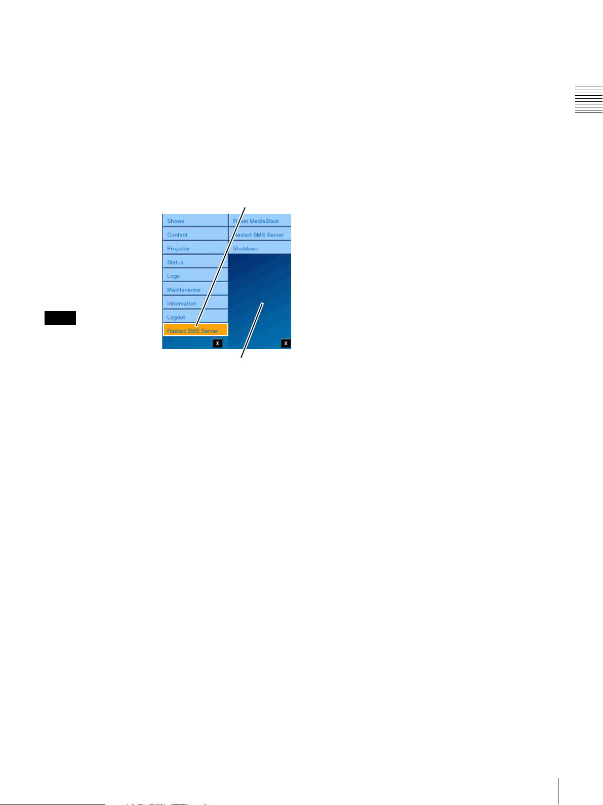
for anything from 3 minutes to 15 minutes. When
cooldown is complete, the Lamp Indicator will change
to red.
3
Initiate Shutdown
Once both the AC-mains and Lamp Indicator LEDs
have changed to red, you can remove the AC-mains
power from the Auditorium Unit. Removal of UPS
AC-mains triggers an automatic shutdown of the
Media Block, the SMS Server and finally the UPS.
Shutdown from Menu
To access System
Tap Restart SMS Server
Shutdown, tap Menu, tap
Restart SMS Server and
then tap System
Shutdown. A
confirmation message
appears. Tap YES to
initiate the Shutdown
process.
Note
Once Shutdown has been
confirmed there is no
way to abort the process.
Restart SMS Server Menu
The Shutdown process
can take an extended period of time if initiated while the
Lamp is ON. This delay is because of the requirement for
cool down of the Projection Lamp. Once the Projector
enters STANDBY mode, (Lamp cooldown has
completed
1
) the SMS Server initiates the sequenced
shutdown process, i.e., Media Block, UPS (delayed
shutdown command which allows for shutdown of the
SMS Server), and the SMS Server.
Chapter 1 User Guide
1.It can take up to 20 minutes for the Lamp cool down
cycle to complete if System Shutdown is executed directly
from Lamp ON mode.
Restart SMS Server
71
Page 72
Theater Setup and
System Security
Chapter 2 Theater Setup and System Security
Overview
Designated users with restricted access to specific options
and adjustments done as part of the normal maintenance of
the system, and to initialization of the Cavity Security
System (CSS) and to generating and managing devices
logs.
Theater Setup
Theater setup functions are related to operations that are
conducted by qualified maintenance personnel on a routine
basis. They are:
• Lamp Replacement (wizard)
The Lamp Replacement Wizard guides you through
the process of entering the 16 digit serial code for the
new Lamp and Resetting the Lamp Timer. Previously,
resetting of the Lamp Timer was found in the
Maintenance functions.
Caution
Lamp replacement should only be performed by
knowledgeable personnel. Refer to the Digital Cinema
Projector Service Manual for additional information.
Chapter
• Registration Adjustment
The Registration Adjustment screens provide access to
the electrical adjustment to the X and Y position of the
Red, Green and Blue images. Previously, the X/Y
adjustment of the images was realized by using the
SRX Controller application.
• Filter Timer Reset
The quality of the air circulating through the Projector
enclosure is filtered. To insure that the air quality is
maintained, these enclosure filters are periodically
replaced.
System Security
System Security functions allow the user to Initialize
Security of the “Cavity” (enclosure) and to set the system’s
Secure Clock
keys during playback.
The System Security features are designed to insure that
any encrypted content cannot be accessed in an unsecure
manner by making the decryption keys unavailable until
the security has been initialized. In addition it insures that
the content cannot be played on the Auditorium Unit
outside of the date/time limitations placed on the content
by the associated decryption key(s) (KDM) by controlling
the ability to reset the system (secure) clock.
1
which governs application of decryption
2
• Lamp Axis Adjustment (wizard)
The Lamp Axis Adjustment Wizard guides you
through the process of adjusting the X, Y, and Z axes
of the new lamp to optimize its location in the
reflector. Previously, Lamp Axis adjustment was
realized by using the use of the SRX Controller
application.
Caution
Lamp Axis adjustment should only be performed by
knowledgeable personnel. Refer to the Digital Cinema
Projector Service Manual for additional information.
72
Overview
1.System Administration function accessible from the
Projectionist Terminal vs. the Screen Management System
Controller application differ. Refer to the SMS Controller
User’s Guide for additional information.
Page 73
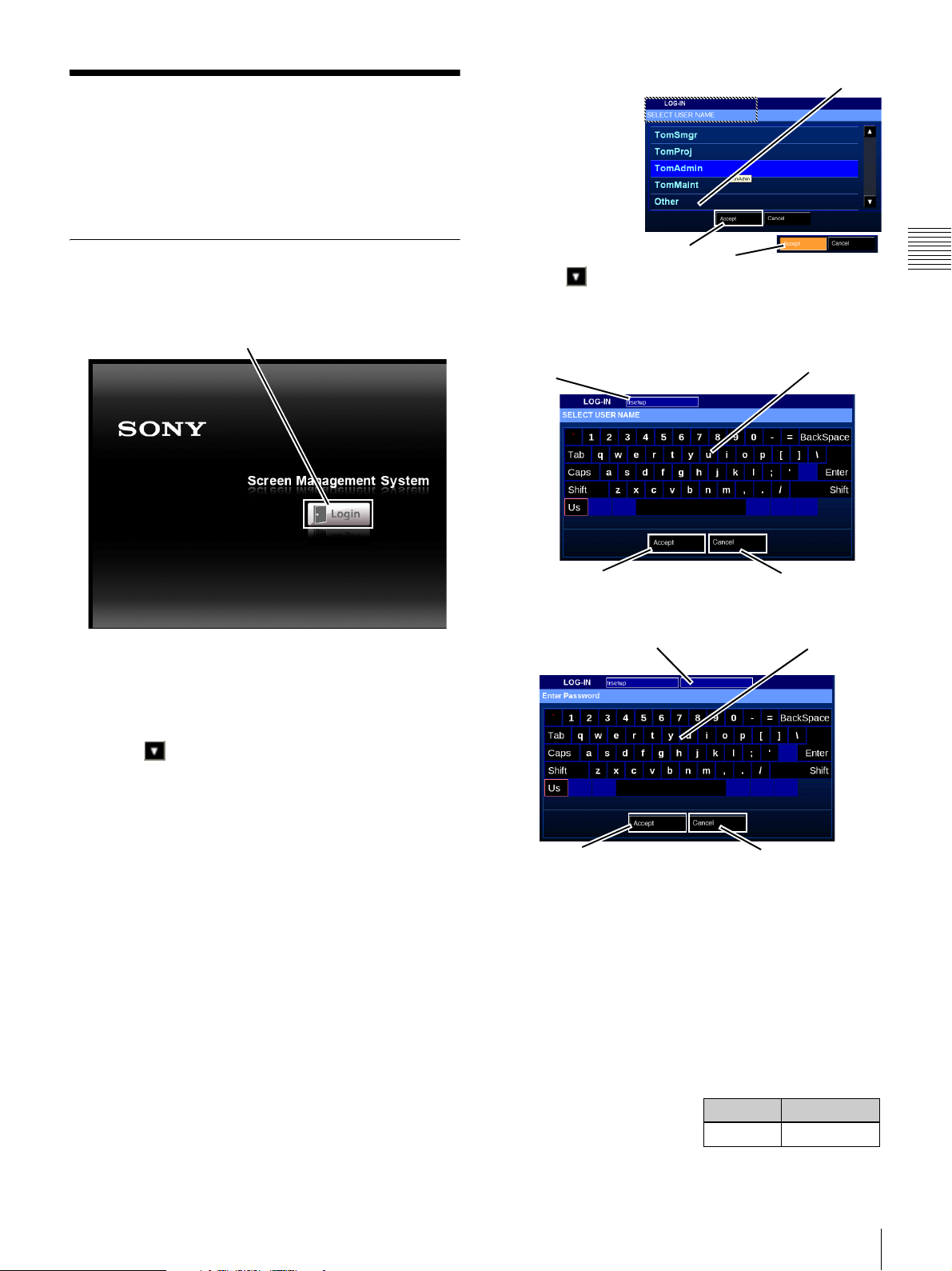
Theater Setup
Theater Setup functions are selected maintenance
operations that are conducted during normal operation of
the Auditorium Unit in the exhibitor’s facility.
Login
To access the Theater Setup functions, tap Login on the
Projectionist Terminal.
Tap Login
3
The Theater
Tap Other
Setup User
(trsetup) may
not appear in the
list of available
User Names.
If trsetup does
not appear in the
list, tap the
Scroll
Tap Accept
Down until
Other can be seen. Tap Other and then tap Accept.
The on-screen keyboard appears. Tap “trsetup” on the
keyboard and then tap Accept.
“trsetup”
Tap “trsetup”
Chapter 2 Theater Setup and System Security
1
The LOG-IN screen appears containing the SELECT
USER NAME list.
2
If the Theater Setup (trsetup)1 User Name is not visible
in the SELECT USER NAME list, tap Scroll
Down until it can be seen, tap trsetup, and then
tap Accept.
The Enter Password screen appears. Using the onscreen keyboard, tap your Password and then tap
Accept.
1.The default login name for maintenance is “trsetup”.
This Role has access to all maintenance items. It is also
possible to use SMS Controller to create other user names
with Role-based access restrictions for specific
maintenance items. For details, refer to the SMS
Controller User’s Guide. When logging in with a user
name that has access restrictions, only menu items that can
be accessed by that user will be shown.
CancelAccept
When you tap Accept the Password box appears.
Masked P/W
4
Using the on-screen keyboard, tap your Password and
Tap Password
CancelAccept
then tap Accept.
If you make an error in entering your Password, tap
Backspace to remove the last character. As you enter
your Password it is masked and appears above the
keyboard.
To abort the Login process, tap Cancel. The Login
process is cancelled and the display returns to the
Login screen.
The default Password for the
“trsetup” User is shown in
the table to the right. The
Login Password
trsetup setup
Password may be changed to
Theater Setup
73
Page 74
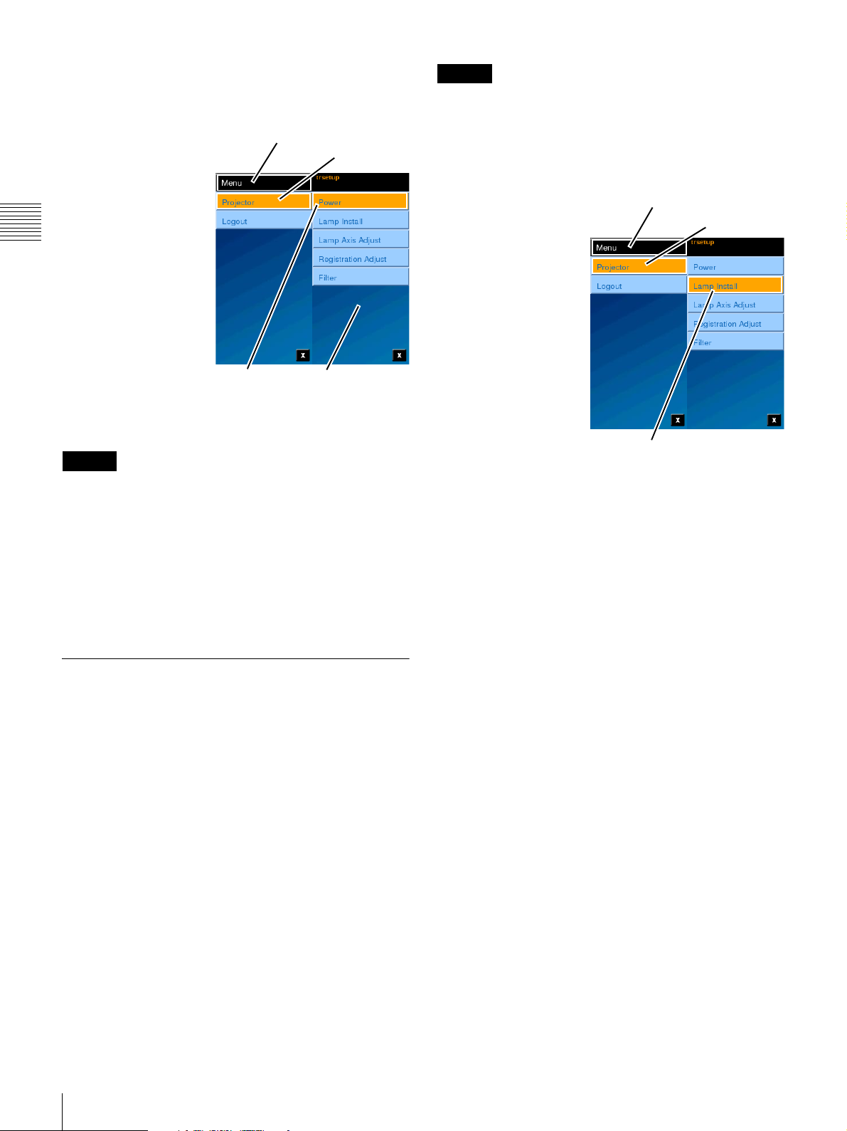
establish security for the user. However, the “trsetup” User
cannot be removed from the system nor can the Real Name
be changed.
On a successful login,
the trsetup screen
1
Tap Men u
Tap Projector
appears. Tap Menu and
then tap Projector to
access the trsetup
menus.
Chapter 2 Theater Setup and System Security
Each trsetup menu is
dedicated to a single
function. Lamp Install
and Lamp Axis Adjust
are used following
replacement of the
projection lamp. Before
performing the Lamp
Install function
(entering a new Lamp
Tap Pow er
Projector
Menu
Serial Code), be sure to
set the projector to STANDBY mode.
Caution
Lamp replacement should only be performed by qualified
personnel wearing protective garments as described in the
Projector Service Manual.
Registration Adjust allows you to move the Red, Green,
and Blue images in an X/Y axis to realize proper alignment
of the images.
Filter allows you to reset the usage timers associated with
the Optical areas in the Projector.
Lamp Installation
The “trsetup” Lamp Install function allows you to enter the
a Serial Code for the replacement lamp. For detailed
information relating to Lamp Replacement refer to the
appropriate Projector Service Manual.
Caution
These settings are only available through the predefined
Theater Setup login thus insuring that these adjustments
are only done by qualified personnel.
Enter Lamp Serial Code
To enter a new lamp
Serial Code, log in as
“trsetup”, tap the Menu,
tap Projector, and then
tap Lamp Install.
Installation of a new
lamp is a multistep
process and once the
lamp is installed the
Lamp Serial Code must
be set and the Lamp Axis
(X, Y, and Z) must be
adjusted for optimum
light output. These two
function can be realized
as separate step and
appear as separate selections under Projector menus.
However, once the Lamp Install Serial Code entry process
is completed the “Wizard” automatically continues on to
the Lamp Axis Adjust steps.
Before installing a new lamp, be sure to turn power to the
projector off. For entering a Serial Code, the projector
must be in STANDBY mode or LAMP OFF mode
Lamp Axis Adjust, the projector must be in LAMP ON
mode. The Wizard automatically sets the required
Projector Power mode. For Lamp Axis adjustment the
Lamp should be on for a minimum amount of time
(approximately 5 minutes) to insure stability of its output.
A countdown timer has been included to indicate how
much time remains before axis adjustment can begin.
Tap Menu
Tap Lamp Instal
Tap Projector
3
. For
Previously, entering the new Lamp Serial Code associated
with the Lamp Installation and replacement process was
realized on the Maintenance->Projector screen or when
using the SRX Controller application. The Serial Code
entry feature has been relocated under the “trsetup” login
and combined with other functions, i.e., Lamp X, Y, and Z
axis alignment and Image Registration
2
, are now available
using the Projectionist Terminal. Previously, these
required using the SRX Controller application.
1.“trsetup” can be disabled through a setting in the SMS
ini file.
2.In previous versions, the Lamp Axis alignment and
Image Registration required use of the SRX Controller
application.
74
Theater Setup
3.If the Projector is in LAMP ON mode, a popup message
will appear advising that the Projector must be OFF for
this operation. Access Projector Control and set either
STANDBY or LAMP OFF mode.
Page 75
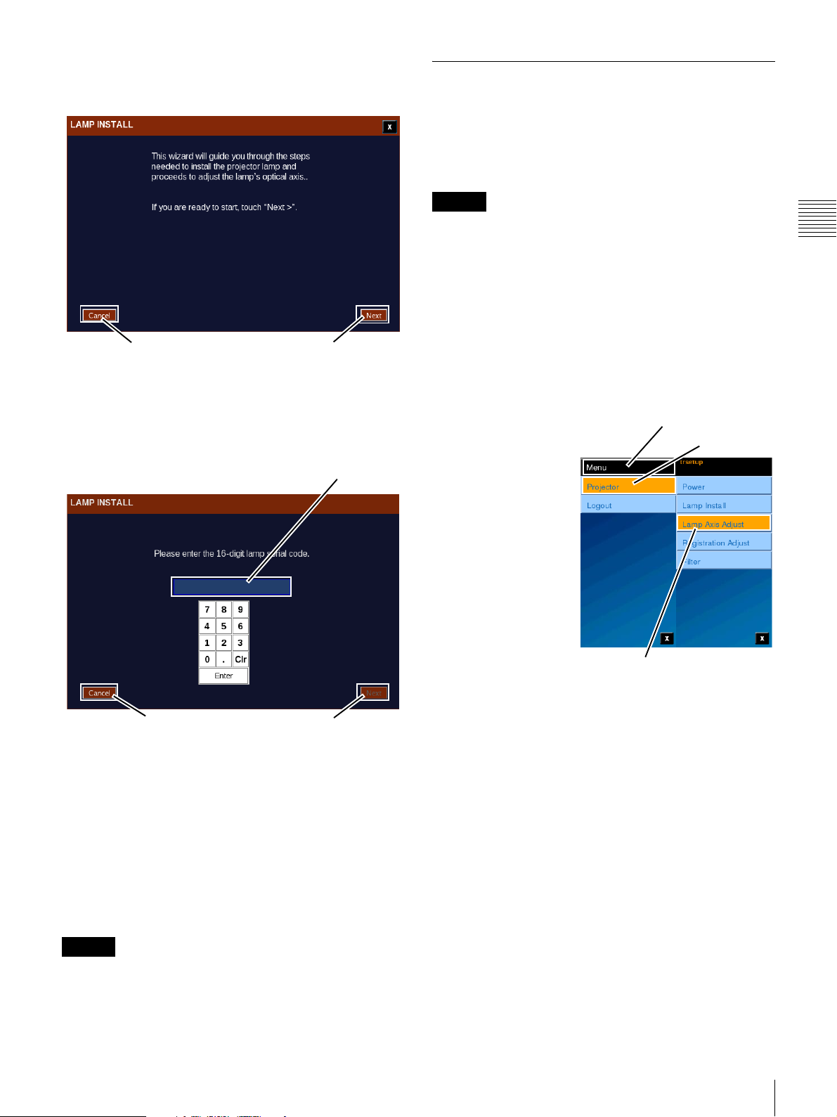
The Lamp Install “wizard” (initial screen shown below)
begins the process of entering the Lamp Serial code for the
new (replacement) lamp.
Cancel
Next
To proceed to Serial Code entry click Next.
The Lamp Serial Code is included with the replacement
(new) lamp. To enter the Lamp Serial Code tap the text
box. An on-screen numeric keyboard appears.
Serial Code Text Box
Lamp Axis Adjust
The Lamp Axis Adjust entry feature has been made
available under the “trsetup” login and combined with
other functions, i.e., Lamp Serial Code entry and Image
Registration
1
. Previously, Lamp Axis Adjust required
using the SRX Controller application.
Caution
• Lamp Axis Adjust is only available through the
pre-defined Theater Setup login thus insuring that this
adjustment is only done by qualified personnel.
• If power to the projector is turned off during Lamp Axis
Adjust, restart the SMS.
Adjust X, Y, & Z Lamp Axis
Installation of a new lamp is a multistep process and once
the lamp is installed the Lamp Axis (X, Y, and Z) must be
adjusted for optimum light output.
Normally, the Lamp
Axis Adjust process is
performed following
Lamp Installation and
setting the Lamp Serial
Code. In this case the
Lamp Install wizard will
automatically progress
from Serial Code entry
to Axis Adjust.
However, if the axis
adjustment cannot be
performed at the time of
installation you can
directly access the Lamp
Axis Adjust steps using
the “trsetup” login.
Tap Lamp Axis Adjust
Tap M e nu
Tap Projector
Chapter 2 Theater Setup and System Security
Cancel
Next
Using the on-screen keyboard, tap the numeric Serial
Code and then tap Enter. The Serial Code is validated for
correct format and Next becomes available. Tap Next to
continue to Lamp Axis Adjust.
To cancel Serial Code entry, if any entry has been made
into the Serial Code text box tap Clr, then tap Enter, and
then tap Cancel. If no entry has been made into the Serial
Code text box simply tap Enter and then tap Cancel. In
either case, a popup confirmation appears. Tap Yes and the
Lamp Install Wizard closes.
Caution
The lamp should be replaced prior to exceeding
recommended operating hours. Refer to the projector
documentation for additional information.
The Wizard automatically checks for the correct Projector
Power mode of operation, e.g., Lamp Axis Adjust requires
LAMP ON mode. For Lamp Axis adjustment the Lamp
should be on for an amount of time (approximately 5
minutes) to insure stability of the lamp output. A
countdown timer has been included to indicate how much
time remains before axis adjustment can begin.
1.In previous versions, Image Registration required use of
the SRX Controller application.
Theater Setup
75
Page 76
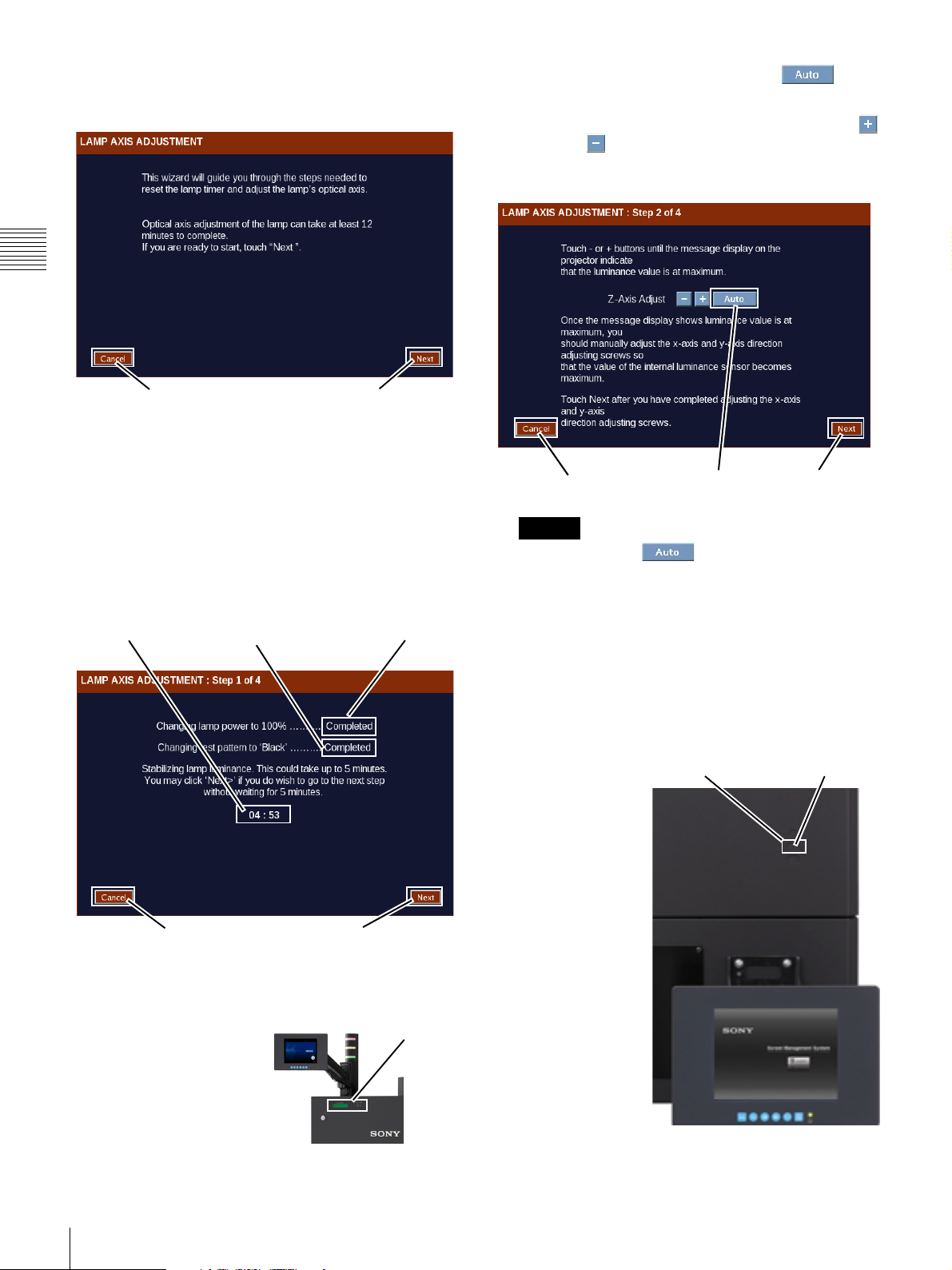
The Lamp Axis Adjust “wizard” (initial screen shown
below) begins the process of entering the Lamp Serial code
for the new (replacement) lamp.
Chapter 2 Theater Setup and System Security
To adjust the Z axis automatically, tap to
obtain the optimum Z axis state.
To adjust manually the Z-Axis, tap either the Plus
or Minus button five times while observing the
reading on the Status Display. Adjust the Z Axis for an
average peak level.
Cancel
Next
To proceed to Lamp Axis Adjust click Next. Step 1 to 4
appears.
1
The Lamp Axis Adjustment wizard will automatically
establish the Lamp at 100% Power and select the
“Black” test pattern.
A countdown timer is also displayed on this screen By
waiting for this timer to expire before continuing the
output of the lamp will have stabalized.
Countdown
Timer
Test Pattern
Setting
Cancel
Lamp Power
Setting
Next
Once the countdown has expired, click Next. Step
2 of 4 appears.
2
During this step you
initially adjust the Z
Axis for a maximum
Projector
Status
Display
indication on the
Projector Status Display
located in the upperright corner of the
projector’s rear panel.
Cancel
Caution
Auto
Next
• You should use to adjust the Z axis under
normal conditions.
• There is a lag between when you tap either the Plus
or Minus button and the observation of a change on
the Status Display. Also, the readings you observe
may have some variation due to the way in which the
arc in the lamp moves slightly.
Continue to adjust the Z-Axis by alternatively tapping
the Plus or Minus button until the value observed on
the Status Display is at a peak.
Once the Z Axis
Access HoleX/Y Axis Adjust
adjustment is
complete,
proceed to adjust
the X and Y
Axis. These
adjustments are
done manually
using a long
5mm Allen key
through an access
hole in the rear
panel. Adjust the
X and Y Axis by
observing the
value on the
Status Display.
Adjust about 1/2
turn and then
observe the
results. Continue adjusting for peak reading. Refer to
76
Theater Setup
Page 77
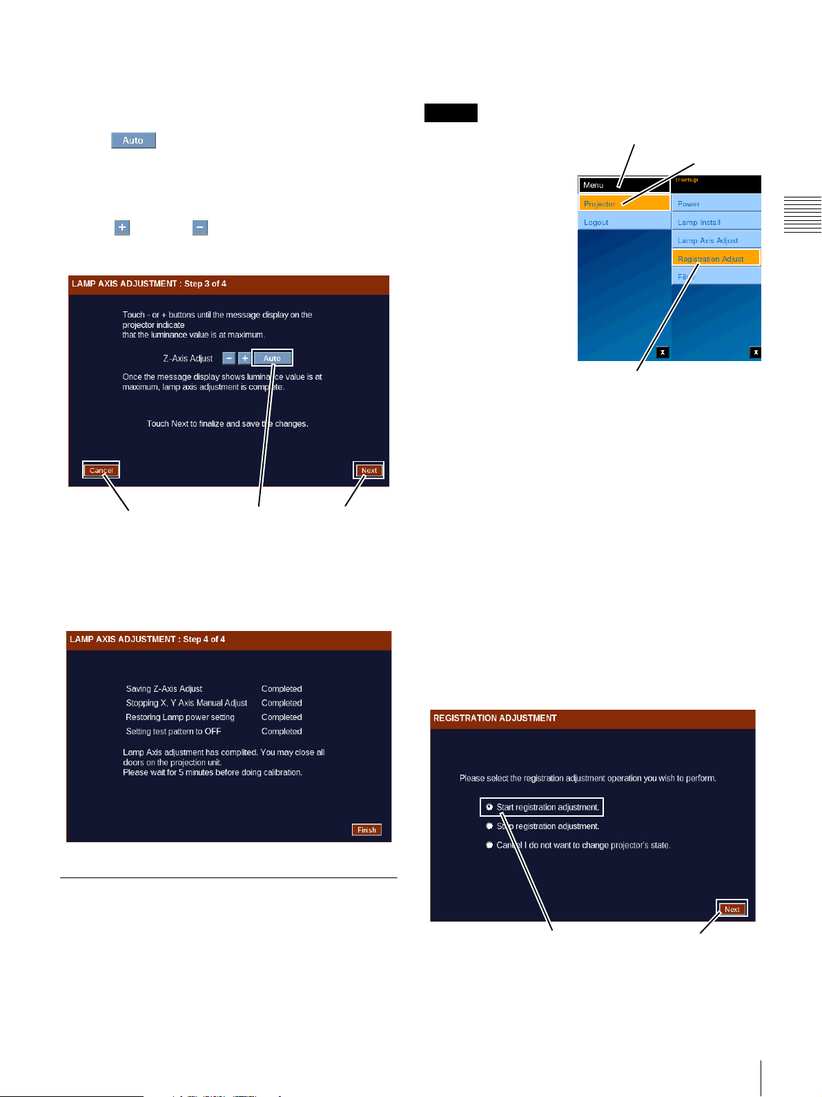
the Projector Service Manual for additional
information.
that these adjustments are carried out by only qualified
personnel.
When complete click Next. Step 3 of 4 appears.
3
Tap to adjust the Z axis again.
During this step you manually optimize the Z Axis
after completing the X and Y Axis adjustments.
Adjust the Z-Axis. Alternately touch and hold the
Plus or Minus buttons while observing the
reading on the Status Display. Attempt to adjust the ZAxis for an average peak level.
Cancel
Auto
Next
When complete click Next. Step 4 of 4 appears.
4
Lamp Axis Adjustment is complete.
Caution
Prior to performing
Registration Adjustment
Tap Menu
Tap Projector
set the Projector to ON
mode. To set On mode,
tap Menu, tap Projector,
tap Power, and then tap
ON. Make sure the
Douser is set to OFF.
Allow a minimum of 30
minutes warm-up to
insure that the imaging
devices have reach their
operating temperature.
Also, prior to performing
Registration Adjustment,
Tap Registration Adjust
verify that focus is
optimized. To adjust the focus, recall the correct lens focus
by selecting an appropriate FUNCTION or re-adjust using
FUNCTION SETUP (Role restricted).
To perform Registration Adjustment, tap Menu, tap
Projector, and then tap Registration Adjust. The
Registration Adjustment screen appears.
Adjustments made during the Registration Adjust process
are applied immediately to the projector. You must be able
to view the auditorium screen in detail as picture
movement is in pixel increments.
Chapter 2 Theater Setup and System Security
The wizard saves the adjustments, restores the original
Lamp Power and sets the Test Patter to OFF.
Registration Adjust
Previously, adjustments to the Red, Green, and Blue image
positioning (X/Y Axis) was realized using the SRX
Controller application. This adjustment is also available
from the Projectionist Terminal. Access to this feature uses
the pre-defined Theater Setup login “trsetup” thus insuring
1
To begin the Registration Adjustment process, select
the Start registration adjustment option and then tap
Next.
The Registration Adjustment screen containing the
Horizontal and Vertical adjustment controls appears.
Start registration...
2
Specific Test Patterns are used during the Registration
Next
Adjustment process.
Theater Setup
77
Page 78
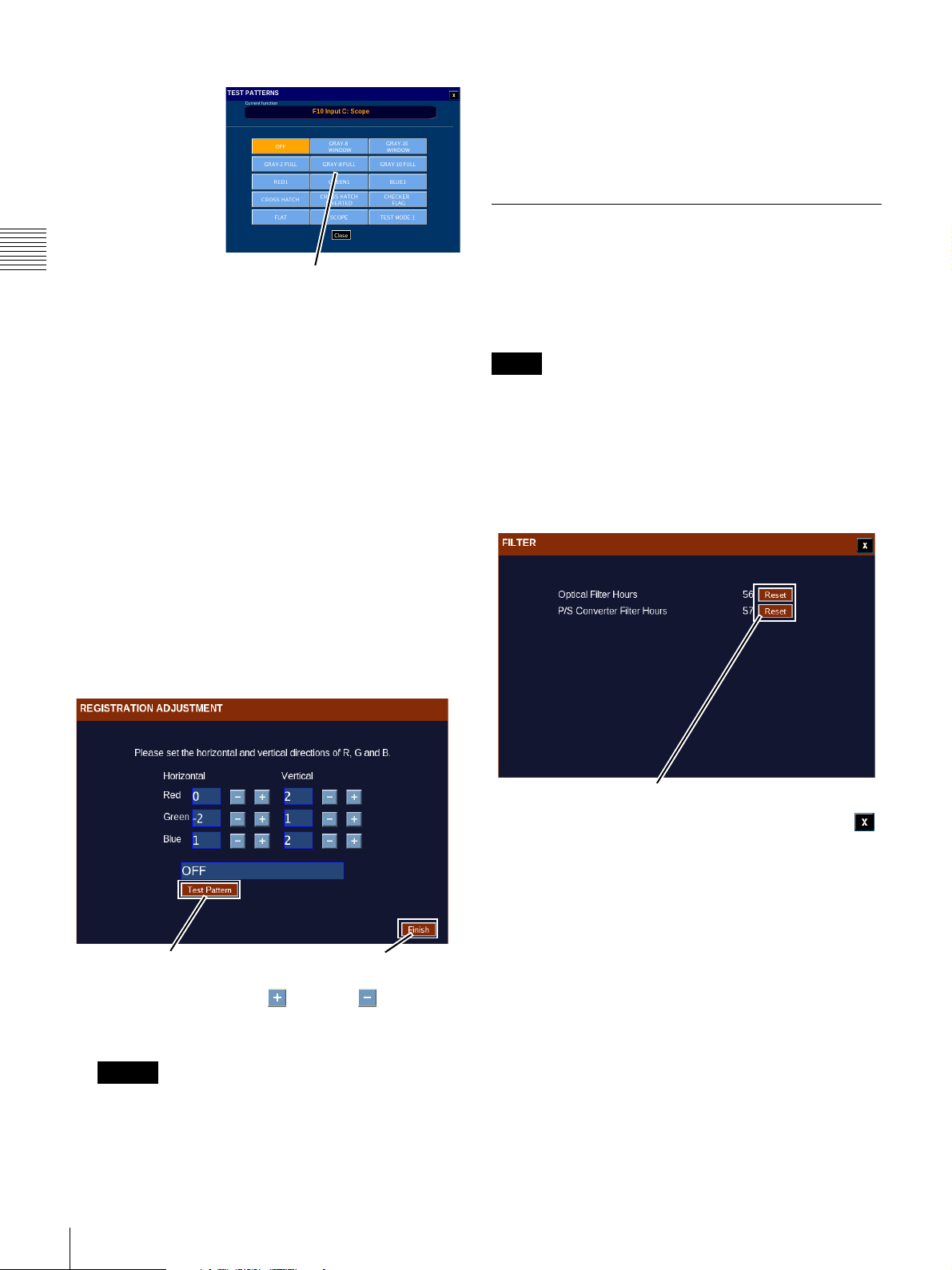
Test Pattern (Select)
To select a test
pattern image,
tap Test
Pattern. The
TEST
PATTERN
popup appears.
The CHECKER
Chapter 2 Theater Setup and System Security
FLAG TEST
PATTERN is
used for
registration
adjustment. To select the TEST PATTERN, tap
CHECKER FLAG.
Additional patterns available are:
• OFF (select when process is complete)
• Gray-8 and Gray-10 (centered white block at 80%
and 100% white respectively)
• Gray-2FULL, Gray-8FULL and Gray-10FULL
(Full Screen at 20%, 80% and 100% white
respectively)
• Red1, Blue1, and Green1 (centered block)
• Crosshatch and Crosshatch Inverted
• Checkered Flag
• Flat (image sizing reference)
• CinemaScope (image sizing reference)
•Test Mode 1
Tap Desired
Pattern to Select
transition to verify lens focus (use crosshatch pattern)
and also to make it easier to see registration errors.
When the image is properly registered, click Next. The
Registration Adjustment screen closes and you are
returned to the Menu,
Filter Timer Reset
The number of hours of operation for the projector’s
optical filters can be tracked separately. This feature
allows you to monitor the number of hours on the filters
and replace them before they effect either airflow or the
quality of cooling air in the projector.
Note
In the SRX-R320 projector, the optical filter operation
hours are tracked. In the R220 projector, the optical filter
and power supply converter filter operation hours are
tracked.
Access to the Filter Timer reset feature uses the predefined Theater Setup login “trsetup” thus insuring that the
Resets are carried out by only qualified personnel.
Registration adjustment range is from +2pixels to 2 pixels with an increment of adjustment of +/-1 pixel.
Test Pattern
Finish
Tap the appropriate Plus or Minus button to
align the Red, Green and Blue images as observed on
the auditorium screen.
Caution
Insure that Lens Focus is optimized prior to starting
the registration process. In some cases it may be
beneficial to use a white sheet of paper placed flat
against the screen so you can see the black/white
Reset
Tap Reset for the associated filter and then tap Close
to return to the Menu.
78
Theater Setup
Page 79
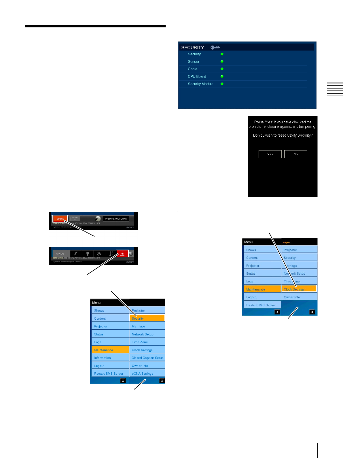
System Security
Two distinct areas are designed to insure that encrypted
content is controlled. Once the Cavity (enclosure) has been
opened, encrypted content cannot be played also after
closing until the Cavity Security System (CSS) has been
initialized by a trusted user.
encrypted Content Elements and their presentation
process.
The other area insures that the secure system clock
governing playback of content cannot be reset to allow
encrypted content by simply changing the system time to
fall within the playable window contained in the
decryption key (KDM). Occasionally, the system (secure)
clock must be reset to compensate for variations. This task
can be done by a trusted user.
Security Initialize
When the security of the Auditorium Unit has been
breached or a tamper switch failure is detected,
presentation is halted and cannot be resumed until Security
has been initialized. The STATUS Alert is set RED, the
MESSAGE Alert is set RED, and a Security Alert Message
is generated and written to the Alert Message Log.
STATUS Alert
MESSAGE Alert
To Initialize Security of
the Auditorium Unit you
access the Security pane,
tap Menu, tap
Maintenance and then
tap Security. The
Security pane appears.
The Security indicator is
illuminated red when a
Security breach has
occurred. While all users
can view the Security
pane (illustrated below),
the ability to initialize the
system security is
restricted to a “trusted”
user. This is done to
insure that only responsible persons can access the interior
of the Auditorium Unit and then resume decryption of
Tap S e c u rity
Maintenance Menu
It you are the “trusted” user
you will also see a popup
(shown to the right)
relating to initializing the
system security.
To initialize Cavity
Security, tap YES. The
Security indicator changes
to green and presentation of
encrypted content can
resume.
Set Time Source for SMS Server
Setting the Time Source
(Reference) for the SMS
Server is realized from
the Clock Settings
screen. When you are a
“trusted” user an
additional menu
selection appears when
you access the
Maintenance menu.
To access the Time
Source setting, tap
Menu, tap
Maintenance, and then
tap Clock Settings. The
CLOCK SETTINGS screen appears.
The CLOCK SETTINGS screen is divided into two areas
Time Settings (SMS Server internal clock) and Secure
Clock (Media Block time reference).
To set the reference source for SMS Server time
synchronization select either the Synchronize with Media
Block or Synchronize with NTP Server option. When
you select Synchronize with NTP Server the IP Address
box appears where you enter the NTP source. Tap the IP
Address box and, using the on-screen keyboard, enter the
IP address of the target NTP Server and then tap Save
Settings. When Synchronize with Media Block is selected
Tap Clock Settings
Maintenance Menu
Chapter 2 Theater Setup and System Security
System Security
79
Page 80
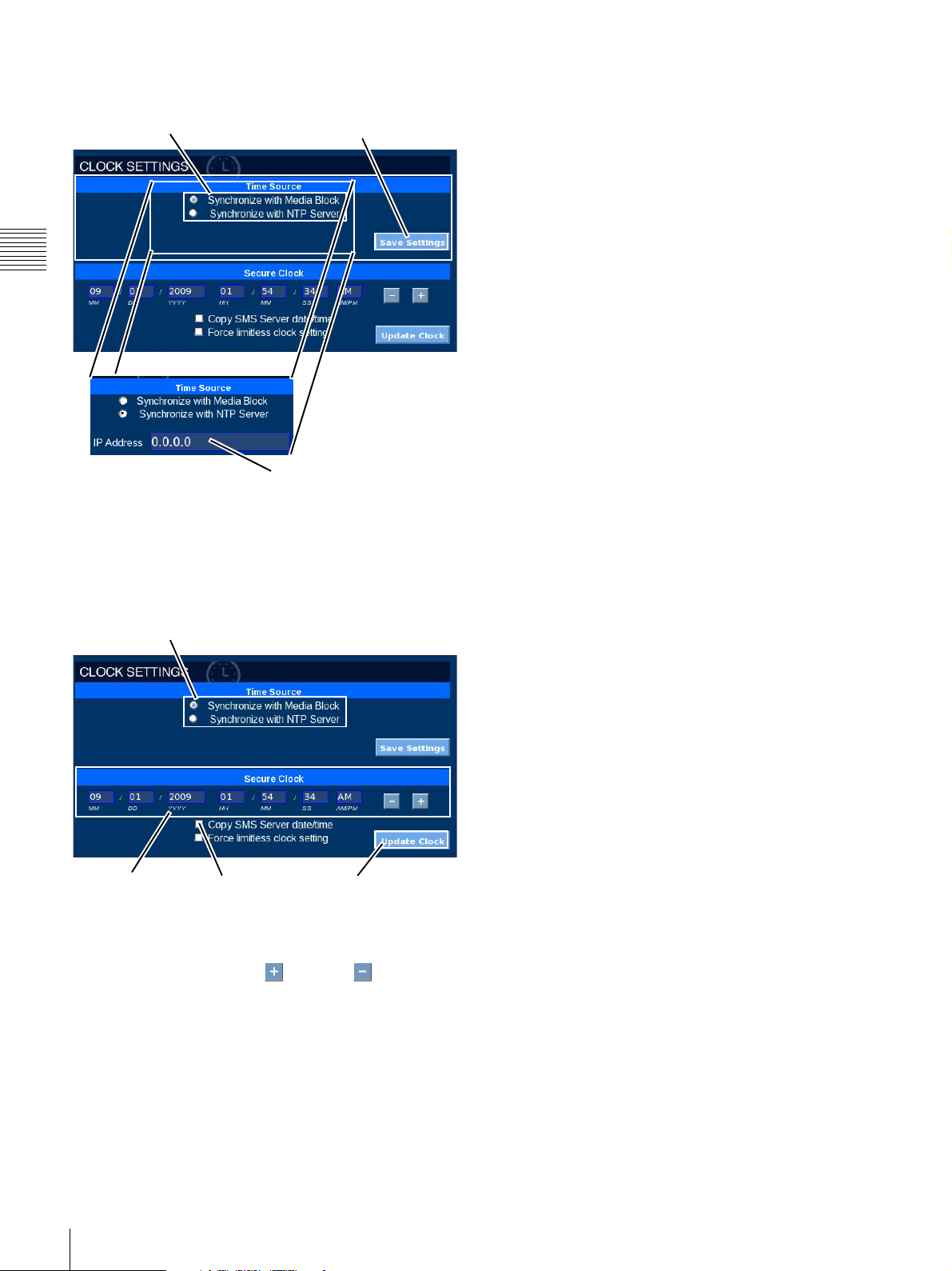
the IP Address box is not present.When the Time Source
has been set, tap Save Settings
Save SettingsMedia Block Time Source
Chapter 2 Theater Setup and System Security
NTP Time Source
If you select Synchronize with Media Block the secure
Clock in the Media Block operates in a standalone mode.
The lower portion of the Clock Settings pane includes the
ability to adjust the secure System Clock in the Media
Block.
Media Block Time Source
Clock Settings Copy from
SMS Server
Update Clock
To adjust the Secure Clock, select the value you wish to
adjust, e.g., tap HH, MM, SS. The value is selected and
then tap the appropriate Plus or Minus button to set
the desired value
1
.
80
1.The maximum change is plus or minus 6 minutes per
year.
System Security
Page 81

Sony Corporation
 Loading...