

Super Audio CD
S200
TM
Player
4-249-411-11(1)
Operating Instructions
Mode d’emploi
US
FR
SCD-XA9000ES
2003 Sony Corporation
WARNING
To prevent fire or shock
hazard, do not expose the
unit to rain or moisture.
To prevent fire, do not cover the ventilation
of the apparatus with news papers, tablecloths, curtains, etc. And don’t place
lighted candles on the apparatus.
To prevent fire or shock hazard, do not
place objects filled with liquids, such as
vases, on the apparatus.
This appliance is
classified as a
CLASS 1 LASER
product. This
marking is located
on the rear exterior.
For the customers in the United States
– Reorient or relocate the receiving antenna.
– Increase the separation between the
equipment and receiver.
– Connect the equipment into an outlet on a
circuit different from that to which the
receiver is connected.
– Consult the dealer or an experienced
radio/TV technician for help.
CAUTION
You are cautioned that any changes or
modification not expressly approved in this
manual could void your authority to operate
this equipment.
Owner’s Record
The model and serial numbers are located
on the rear of the unit.
Record the serial number in the space
provided below. Refer to them whenever
you call upon your Sony dealer regarding
this product.
Model No. SCD-XA9000ES
Serial No. _________________________
CAUTION
The use of optical instruments with this
product will increase eye hazard.
Welcome!
Thank you for purchasing the Sony Super
Audio CD Player. Before operating the
unit, please read this manual thoroughly
and retain it for future reference.
About This Manual
The instructions in this manual is for SCDXA9000ES.
Conventions
• Instructions in this manual describe the
controls on the player.
You can also use the controls on the
remote if they have the same or similar
names as those on the player.
• The following icons are used in this
manual:
Indicates that you can do the
Z
task using the remote.
This symbol is intended to alert the
user to the presence of uninsulated
“dangerous voltage” within the
product’s enclosure that may be of
sufficient magnitude to constitute a
risk of electric shock to persons.
This symbol is intended to alert the
user to the presence of important
operating and maintenance
(servicing) instructions in the
literature accompanying the
appliance.
WARNING
This equipment has been tested and found
to comply with the limits for a Class B
digital device, pursuant to Part 15 of the
FCC Rules. These limits are designed to
provide reasonable protection against
harmful interference in a residential
installation. This equipment generates,
uses, and can radiate radio frequency
energy and, if not installed and used in
accordance with the instructions, may
cause harmful interference to radio
communications. However, there is no
guarantee that interference will not occur in
a particular installation. If this equipment
does cause harmful interference to radio or
television reception, which can be
determined by turning the equipment off
and on, the user is encouraged to try to
correct the interference by one or more of
the following measures:
For the customers in Canada
This Class B digital apparatus complies
with Canadian ICES-003.
CAUTION
TO PREVENT ELECTRIC SHOCK,
MATCH WIDE BLADE OF PLUG TO
WIDE SLOT, FULLY INSERT.
Don’t throw away the
battery with general house
waste, dispose of it
correctly as chemical waste.
Indicates hints and tips for
z
making the task easier.
US
2

Features
TABLE OF CONTENTS
About the Super Audio CD
• Super Audio CD is a new high-quality audio disc
standard where music is recorded in the DSD (Direct
Stream Digital) format (conventional CDs are recorded
in the PCM format). The DSD format, using a sampling
frequency 64 times higher than that of a conventional
CD, and with 1-bit quantization, achieves both a wide
frequency range and a wide dynamic range across the
audible frequency range, and so provides music
reproduction extremely faithful to the original sound.
• The Super Audio CD has two types; a 2 channel stereo
disc and a Multi-channel disc which holds up to 6
independent channels. The multi-channel characteristic
of the Super Audio CD features a speaker allocation
system basically similar to the 5.1 channel output of
current AV systems.
Features of the player
This player is designed to play back 2-channel and multichannel Super Audio CDs, and conventional CDs, and
provides the following features:
• Mounted with a Discrete Dual Laser Optical Pickup,
capable of reading a Super Audio CD or conventional
CD depending on the exclusive wavelength.
• Quicker track access performance enabled by an
advanced servo mechanism.
• A Multi-Channel Management function that allows you
to adjust the multi-channel playback environment
according to the allocation and size of your speakers.
• A Super Audio D/A Converter and Direct Digital Sync
System, which allows higher-quality sound
reproduction.
• An i.LINK digital transmission system that provides
higher quality sound and lets you make connections
with just 1 i.LINK cord instead of 6 pin cords.
• This player complies with DTLA copy protection
technology (Revision 1.2).
Others
• A Super Audio CD can mark up to 255 track/index
numbers. This feature applies to SCD-XA9000ES.
• The supplied remote is capable of controlling both the
SCD-XA9000ES and a conventional Sony CD player.
Getting Started 4
Before You Start the Hooking Up 4
Hooking Up the Audio Components 5
Location and Functions of Parts 10
Front Panel Parts Descriptions 10
Rear Panel Parts Descriptions 12
Remote Parts Descriptions 13
Playing Discs 14
Compatible Disc Types 14
Playing a Disc 16
Using the Display 17
Locating a Specific Track 20
Locating a Particular Point in a Track 20
Playing Tracks Repeatedly 21
Playing Tracks in Random Order (Shuffle Play) 22
Creating Your Own Program (Program Play) 23
Listening to a CD Using a Filter (Digital Filter
Function) 24
Setting the DIGITAL OUT on/off 24
Listening to a Multi-channel Super Audio CD
(Multi-channel management function) 25
Additional Information 29
Precautions 29
Notes on Discs 30
Troubleshooting 31
Display Messages 32
Specifications 32
Index 34
US
US
3
Getting
Before You Start Hooking
Up
Started
This chapter provides information on
the supplied accessories and how to
connect various audio components to
the Super Audio CD player. Be sure
to read this chapter thoroughly before
you actually connect anything to the
player.
Checking the supplied accessories
This player comes with the following items:
• Audio connecting cord
phono jack × 2 (Red and White) y phono jack × 2 (Red
and White) (3)
phono jack × 1 (Black) y phono jack × 1 (Black) (2)
• i.LINK connecting cord (1)
• Remote commander RM-SX700 (1)
• Size AA (R6) batteries (2)
• AC power cord (1)
• Plug adapter (1)
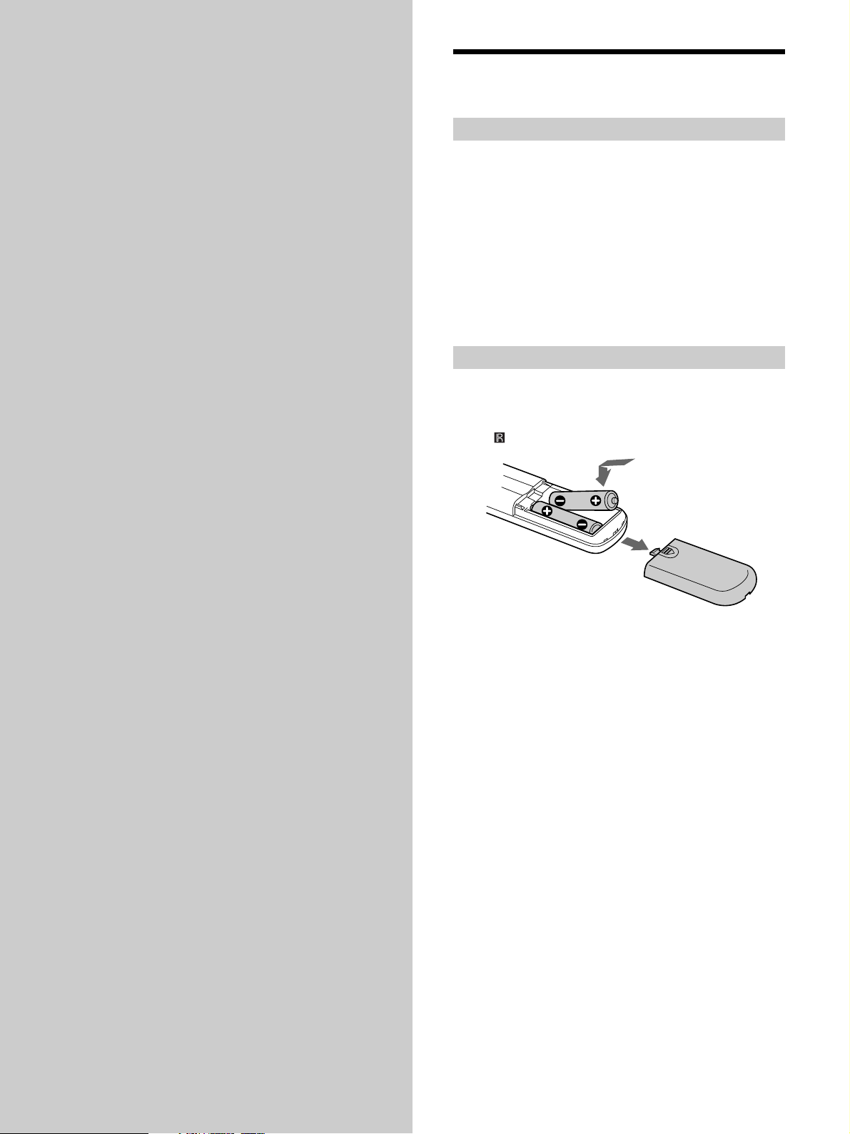
Inserting batteries into the remote
Insert two size AA (R6) batteries into the battery
compartment with the + and – correctly oriented to the
markings. When using the remote, point it at the remote
sensor
on the player.
z
When to replace the batteries
Under normal conditions, the batteries should last for about six
months. When the remote no longer operates the player, replace
both batteries with new ones.
Notes
• Do not leave the remote in an extremely hot or a humid place.
• Do not drop any foreign object into the remote casing,
particularly when replacing the batteries.
• Do not use a new battery with an old one.
• Do not expose the remote sensor to direct sunlight or lighting
apparatus. Doing so may cause a malfunction.
• If you do not intend to use the remote for an extended period
of time, remove the batteries to avoid possible damage from
battery leakage and corrosion.
US
4

Hooking Up the Audio Components
Connect the Super Audio CD player to an audio
component. Be sure to turn off the power of all
components before making connections and connect
securely to prevent noise.
If you have an amplifier equipped with the 5.1CH input
jacks (multi-channel amplifier, AV amplifier, etc.) and
connect the player and the amplifier via the ANALOG
5.1CH OUT jacks, you can play multi-channel Super
Audio CDs and enjoy multi-channel playback.
For normal playback, connect the player and an amplifier
via ANALOG 2CH OUT jacks.
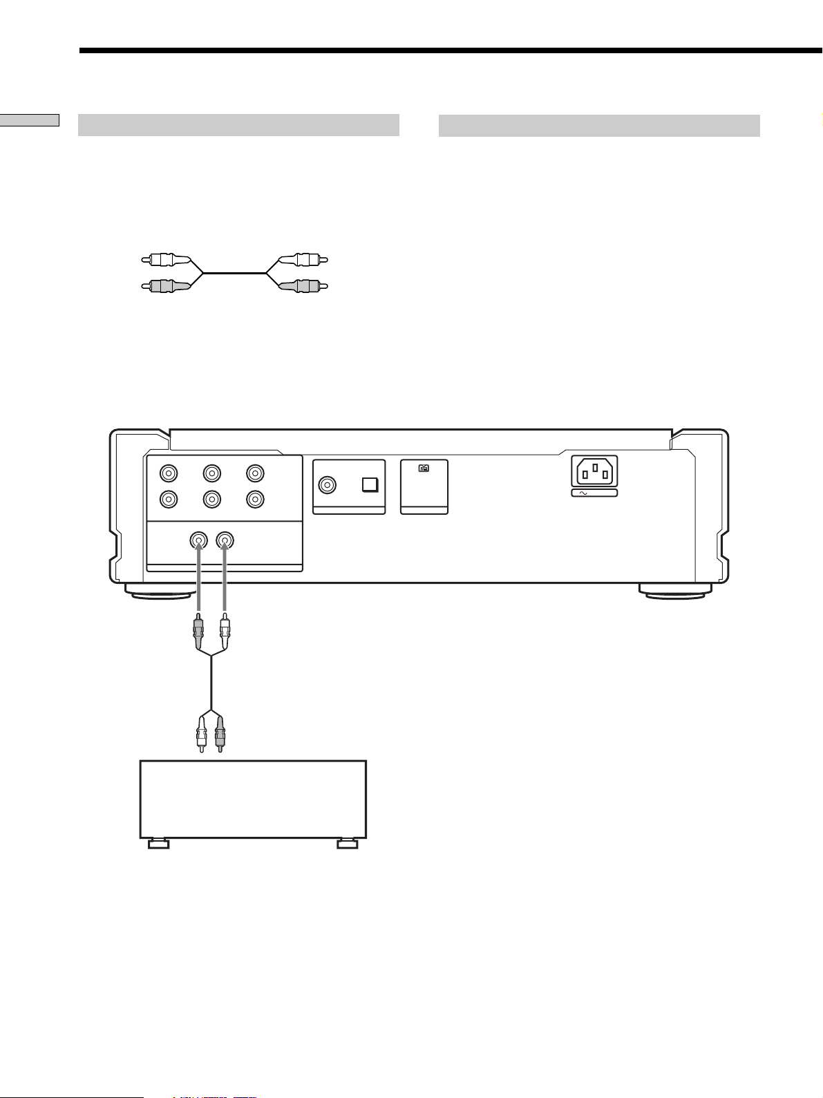
Connecting via ANALOG 5.1CH OUT jacks
Use audio connecting cords for this connection. Connect the
ANALOG 5.1CH OUT jacks (FRONT L/R, SURR L/R, CENTER,
SUBWOOFER) to the corresponding jacks on your amplifier. For
FRONT or SURR connection, use the connecting cords (Red and
White jacks) and be sure to match the color-coded pin to the
appropriate jacks: white (left) to white and red (right) to red. For
CENTER and SUB WOOFER connection, use the connecting
cords (Black).
FRONT or SURR connection
Audio connecting cords (Red and White) (supplied)
CENTER or SUB WOOFER connection
Audio connecting cords (Black) (supplied)
Black
Black
Notes
• Even when you make Multi-channel connections, be sure to
also connect the ANALOG 2CH OUT jacks using another audio
connecting cord so that you can play CDs (or SACDs) when
you set the input selector of your amplifier to CD (or SACD)
input .
• During playback of a conventional CD or a 2CH Super Audio
CD, same signal is output from the ANALOG 5.1CH FRONT
L/R jacks and ANALOG 2CH OUT jacks. The signal is output
in higher quality from the ANALOG 2CH OUT jacks (see page
9).
• During playback of a Multi-channel Super Audio CD, the same
signal is output from the ANALOG 5.1CH FRONT L/R jacks
and ANALOG 2CH OUT jacks. (The downmixed signal of the
Multi-channel siginal is not played back.)
• There are 5CH, 4CH, and 3CH Super Audio CD. When you
play these disc, the signal is not output from all of the
ANALOG 5.1CH OUT jacks. For details of the playback, see the
cover or instructions of the Super Audio CD.
Getting Started
White (L)
Red (R)
To FRONT IN
jacks (L/R)
L
RR
L
FRONT SURROUND SUB WOOFER
LR
ANALOG
To SURROUND or
REAR IN jacks
(L/R)
CENTER
5.1CH OUT
2CH OUT
White (L)
Red (R)
OUT
DIGITAL(CD)
OPTICALCOAXIAL
i.LINK S200
To CENTER IN
jack
AUDIO OUT
To SUB WOOFER
IN jack
AC IN
Multi-channel amplifier,
AV amplifier, etc.
US
5
Hooking Up the Audio Components
Getting Started
Connecting via ANALOG 2CH OUT jacks
Use an audio connecting cords for this connection. Connect the
ANALOG 2CH OUT L/R jacks to the CD (SACD) input jacks of
your amplifier. Be sure to match the color-coded pin to the
appropriate jacks: white (left) to white and red (right) to red.
Audio connecting cords (Red and White) (supplied)
White (L)
Red (R)
Note
During playback of a Multi-channel Super Audio CD, the same
signal is output from the ANALOG 5.1CH FRONT L/R jacks and
ANALOG 2CH OUT jacks. (The downmixed signal of the Multichannel signal is not played back.)
L
RR
L
FRONT SURROUND SUB WOOFER
LR
CENTER
5.1CH OUT
2CH OUT
White (L)
Red (R)
OPTICALCOAXIAL
OUT
DIGITAL(CD)
About the ANALOG 2CH OUT
When you play a conventional CD or a 2CH Super Audio CD, the
stereo signal is sent to the FRONT, SURROUND, and CENTER/
SUB WOOFER D/A Converters, and each signal is combined
after D/A conversion, then combined signal is output from the
2CH OUT jacks.
Since each digital signal is converted to analog signal by three
converters, this system offers a three-fold improvement in signal
quality and a root three-fold noise ratio, the result is an improved
signal to noise ratio. Therefore, a high quality signal is output
from the ANALOG 2CH OUT jacks.
During playback of a Multi-channel Super Audio CD, the signal
conversion described above is not applied, and the same signal is
output from the ANALOG 5.1CH FRONT L/R jacks and
ANALOG 2CH OUT jacks. (The downmixed signal of the Multichannel signal is not played back.)
AUDIO OUT
i.LINK S200
AC IN
To CD (SACD) IN
jacks (L/R)
ANALOG
Stereo amplifier, etc.
US
6
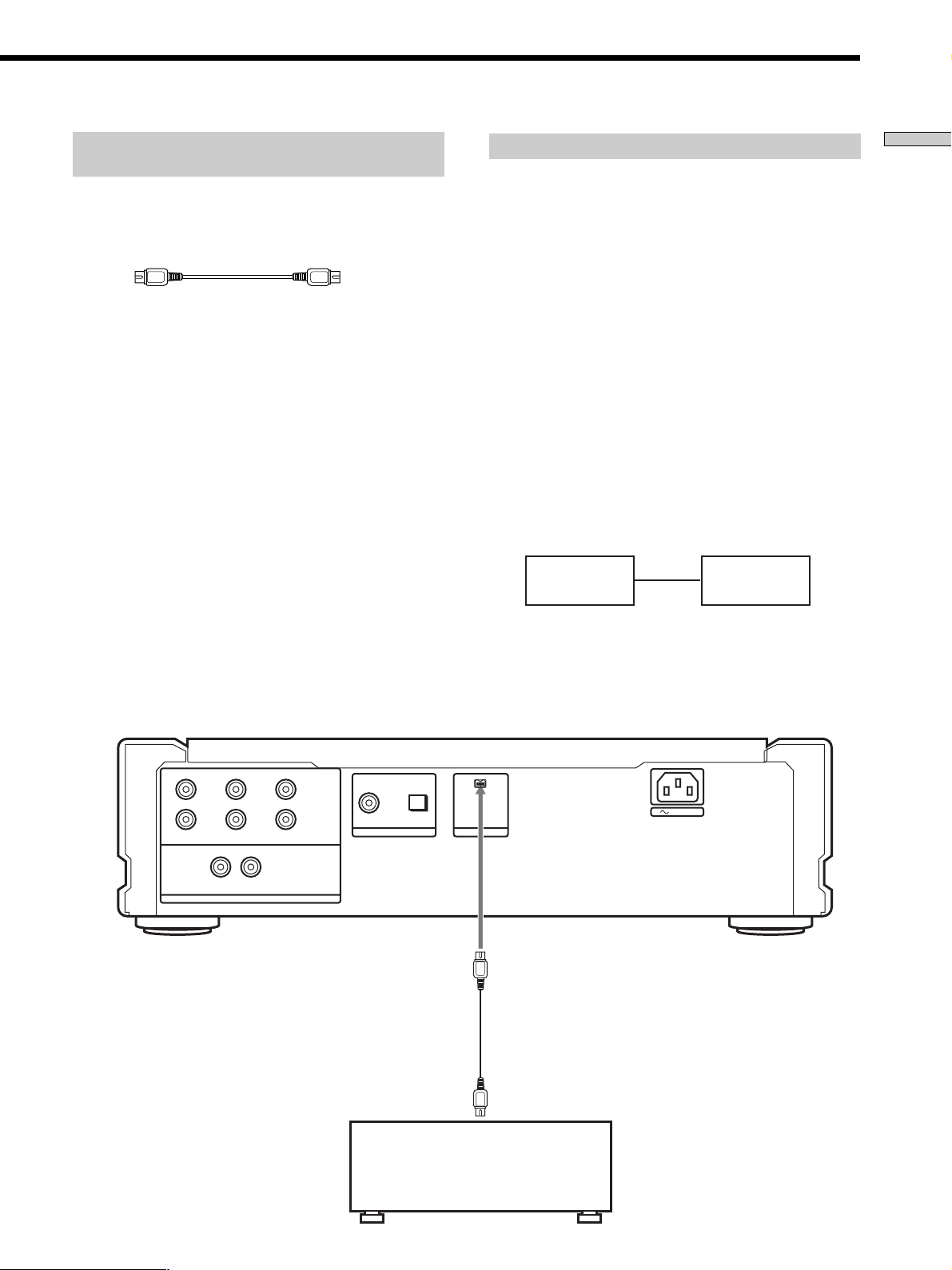
Connecting via i.LINK S200 AUDIO OUT
jack
Connect SCD-XA9000ES to STR-DA9000ES/TADA9000ES with the supplied i.LINK connecting cord.
i.LINK connecting cord (supplied)
Notes
• i.LINK connections are only possible between this player and
STR-DA9000ES/TA-DA9000ES. This player has some
restrictions on i.LINK functions and may not operate properly
if connected to components other than STR-DA9000ES/TADA9000ES.
• If a metal object should fall into the i.LINK S200 AUDIO OUT
jack, short-circuiting may occur and damage the components.
• Be sure to insert the plug firmly to prevent malfunction.
• See page 32 for information about compatible signals.
• Some i.LINK components comply with copy protection
technology and handle encrypted signals. This player complies
with the DTLA copy protection technology (Revision 1.2).
•“i.LINK“ lights up in the display when this player is ready to
output the audio signals from the i.LINK S200 AUDIO OUT
jack.
Establishing a LINC
Before an audio signal can be transmitted between i.LINK
components, a LINC (Logical INterface Connection) must
first be established between the receiving component (of
the audio signal) and the sending component.
Establishing a LINC means establishing a logical path for
the transmission of digital audio signals between the two
components. Each logical path has an ID number. Since
the component that sends an audio signal must output the
signal to a path, and the component that receives the
signal must input it from the same path, the path must be
mutually known by both components. During the
establishment of a LINC, the following communication
occurs between the two i.LINK components.
Example
STR-DA9000ES/TA-DA9000ES establishes a LINC with SCDXA9000ES.
1 STR-DA9000ES/TA-DA9000ES sends a request and path
information to SCD-XA9000ES to establish a transmission
path for the audio signal.
1
STR-DA9000ES
TA-DA9000ES
,
SCD-XA9000ES
2
<
2 SCD-XA9000ES responds to STR-DA9000ES/TA-DA9000ES,
agreeing to the establishment of a LINC.
The digital audio signal transmission becomes possible only
after the communication described above has occurred and a
LINC has been established.
Getting Started
L
RR
L
FRONT SURROUND SUB WOOFER
LR
ANALOG
CENTER
5.1CH OUT
DIGITAL(CD)
2CH OUT
To i.LINK S200
AUDIO IN jack
OUT
OPTICALCOAXIAL
AUDIO OUT
i.LINK S200
AC IN
STR-DA9000ES
TA-DA9000ES
US
7
Hooking Up the Audio Components
Getting Started
Listening in high fidelity H.A.T.S. (High
quality digital Audio Transmission
System) function
When the H.A.T.S. function of STR-DA9000ES/TADA9000ES is “ON” digital audio signals are momentarily
stored in a buffer, then read with exact timing before
being converted to analog. This eliminates the jitter
(timing lapses) that sometimes occur during digital signal
transmission and greatly improves sound quality.
When this function is turned on, the H.A.T.S. indicator on
the front panel of STR-DA9000ES/TA-DA9000ES lights up
whenever the digital audio signal is input to the receiver.
When not using this function, set it to “OFF” on STRDA9000ES/TA-DA9000ES. For details, refer to the
Operating Instructions supplied with STR-DA9000ES/TADA9000ES.
Notes
• Because of the way the H.A.T.S. function operates, a slight time
lag is introduced between each operation (e.g., pressing play,
stop, or pause) and its implementation. The duration of this
time lag may be different for CD and Super Audio CD sources.
• The H.A.T.S. function works only with H.A.T.S. compatible
components.
• The H.A.T.S. function works only when this player is selected
as the input source by a single STR-DA9000ES/TA-DA9000ES.
This is because the receiving component (STR-DA9000ES/TADA9000ES) controls the rate of digital audio signal
transmission from the player. To insure proper signal
transmission within the i.LINK configuration, only one
component can receive the digital audio signals output from a
source component.
Copyright
i.LINK components complying with copyright protection
incorporate digital data copy protection technology. One
such technology is the DTLA (The Digital Transmission
Licensing Administrator) recognized by the Copy
Protection Technical Working Group. It may not be
possible to make digital copies of copy restricted digital
data (video/audio/data) using i.LINK signals between
components that comply with the DTLA copy protection
technology. In addition, it may not be possible to transfer
digital data (video/audio/data) via i.LINK between
i.LINK components which comply with DTLA copy
protection and i.LINK components which do not.
• i.LINK is a designation referring to IEEE 1394-1995 and IEEE
1394a-2000. i.LINK and the i.LINK logo “TM” are trademarks of
Sony Corporation.
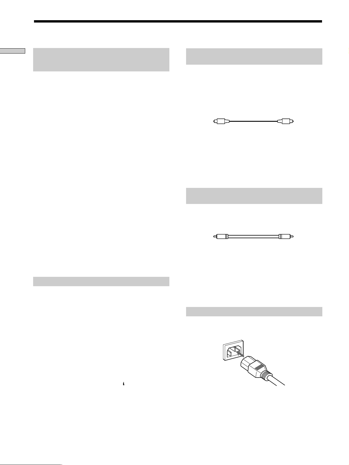
Connecting via DIGITAL (CD) OUT OPTICAL
connector
Use an optical digital cable for this connection. When connecting
the optical digital cable to the DIGITAL (CD) OUT OPTICAL
connector, take the cap off the connectors and push the cable
plugs in until they click into place.
Be careful not to bend or twist the optical cable.
Optical digital cable (not supplied)
Note
Only the audio signals of conventional CDs can be output from
the DIGITAL (CD) OUT connectors. Those of the Super Audio
CD cannot be output through DIGITAL (CD) OUT.
When the i.LINK indicator lights up
No signal is output from DIGITAL (CD) OUT OPTICAL
connector.
Connecting via DIGITAL (CD) OUT COAXIAL
connector
Use a coaxial digital cable to connect the audio components
equipped with coaxial digital input connectors.
Coaxial digital cable (not supplied)
Note
Only the audio signals of conventional CDs can be output from
the DIGITAL (CD) OUT connectors. Those of the Super Audio
CD cannot be output through DIGITAL (CD) OUT.
When the i.LINK indicator lights up
No signal is output from DIGITAL (CD) OUT COAXIAL
connector.
Connecting the AC power cord
Connect the supplied AC power cord to the AC IN terminal on
the player and to the mains.
US
8

About the AC power cord
The supplied AC power cord has a 3-pronged grounded plug. If
you are using 3-pronged grounded mains, the plug can be
inserted directly into the mains. However, if the socket is a 2pronged grounded mains, use the supplied plug adapter or a
commercially available plug adapter.
3-pronged grounded mains
Note on the output jacks
This player is equipped with a Tri-Powered D/A Converter
System and a Multi Channel Management function. The usable
output settings differ depending on the mode you select as
follows. For details, refer to the Operating Instructions.
Source Multi 2CH 5.1CH
Channel OUT OUT jack
Management jacks jacks jacks
CD
—*
Super Audio CD Direct
1
a*
a*
2
2
aa*
aa*
PHONES DIGITAL
(CD) OUT
2
2
a*
×
4
Getting Started
2-pronged polarized mains
• When the width of the mains are a different size
Use the supplied plug adapter.
3 to 2-prong polarized
plug adapter
N pole
• When the width of the mains are the same size
Use a commercially available plug adapter. In this case, you
can check the polarity of the mains with a commercially
available spark-testing screwdriver. It is the pronged ground
that does not light the neon grow lamp even if you insert the
spark-testing screwdriver into the mains. Insert the blades so
that the “N pole” can be inserted to the ground on the plug.
If noise (hum) is produced
Noise may be caused by an electric potential difference on the
ground circuit.* In this case, use the supplied plug adapter and
be careful not to connect the ground lead to anything.
* Although the ground of the domestic mains is normally a
safety ground, a few electrical potential differences may be
produced, depending on the mains. Therefore, use of the
supplied 3-pronged mains lead may lessen the quality of the
audio signal or may produce humming noise.
(2 channel) 2ch + SW
Super Audio CD
(Multi-channel)
—*
aaa ×
1
a*
3
aa*
3
×
*1Not available for CDs or Super Audio CDs.
*2Output through the Tri-Powered D/A Converter.
*3The same signal that is output from the ANALOG 5.1CH OUT
FRONT L/R jacks is output.
*4Only when “D. OUTPUT” is set to “ON” (page 24).
Note
Tri-Powered D/A Converter System works only for 2 channel
signals from 2 CH OUT jacks.
When the i.LINK indicator lights up
• No signal is output from all the other jacks (ANALOG 2CH
OUT jacks, ANALOG 5.1CH OUT jacks, PHONES jack,
DIGITAL (CD) OUT jacks).
• The Multi Channel Management function does not work.
z
When you want to listen to the sound through headphones
when the i.LINK indicator lights up
Connect the headphones to the PHONES jack on the amplifier,
not on this player.
US
9

Location and
Functions of
Parts
This chapter tells you about the
location and functions of the various
buttons and controls on the front and
rear panels and the supplied remote.
Further details are provided on the
pages indicated in parentheses.
It also tells you about the information
that appears in the display window.
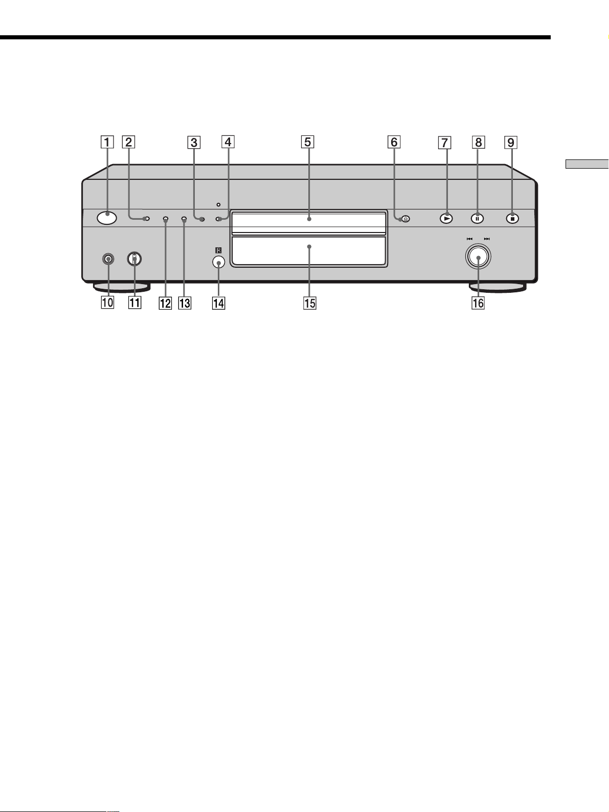
Front Panel Parts
Descriptions
1 POWER switch (16)
Press to turn on the player.
2 TIME/TEXT button (17)
Each time you press the button, the playing time of the
track, the total remaining time on the disc, or TEXT
information appears in the display.
3 SACD/CD button (16)
Each time you press the button while playing back a
hybrid disc, the layer to be played back switches
between the HD (Super Audio CD) layer and the CD
layer.
4 i.LINK button (16)
Each time you press the button, the signal output
switches between the i.LINK jack and the analog jacks.
i.LINK indicator (16)
Lights up when the i.LINK function is used.
5 Disc tray (16)
Press A OPEN/CLOSE to open/close the disc tray.
10
US
Location and Functions of Parts
POWER
PHONES
TIME/TEXT
PHONE LEVEL
MIN MAX
MENU
MULTI/2CH
SACD/CD
I.Link
6 A OPEN/CLOSE button (16)
Press to open or close the disc tray.
7 N button (16)
Press to start play.
8 X button (16)
Press to pause play.
9 x button (16)
Press to stop play.
0 PHONES
Connect the headphones.
During playback of a Multi-channel Super Audio CD,
the same signal that is output from the ANALOG
5.1CH FRONT L/R jacks is output from the PHONES
jack.
qa PHONE LEVEL
Adjust the headphones volume.
AMS
PUSH
ENTER
qs MENU (15, 26–28)
Press to enter the menu.
Press to exit from the menu and return to the normal
display.
qd MULTI/2CH button (16)
Press to select the playback area when the 2 channel +
Multi-channel Super Audio CD (page 15) is loaded.
qf Remote sensor
qg Display window (17)
Shows various information.
qh . AMS > dial (AMS: Automatic Music Sensor)
(20)
When you turn the . AMS > dial
counterclockwise by one click, you go back to the
preceding track; when you turn the . AMS >
dial clockwise by one click, you go to the succeeding
track.
11
US
 Loading...