

Page 1
SCD-C2000ES
SERVICE MANUAL
Ver. 1.1 2005.05
SUPPLEMENT-1
Subject: TEST MODE and ELECTRICAL ADJUSTMENT
US Model
Canadian Model
9-879-094-81
Page 2
SCD-C2000ES
SECTION 1
TEST MODE
1. Setting Method of The Test Mode
While press [MENU] and l AMS L dial, press the [POWER] button to turn the power on and enter the Test Mode and display “DIA G
MODE”.
2. Operating The Test Mode
Procedure:
1. Turn the l AMS L dial to select the command number (hexadecimal number) (refer to the following table for command
number).
2. Press the l AMS L dial to execute the selected command item.
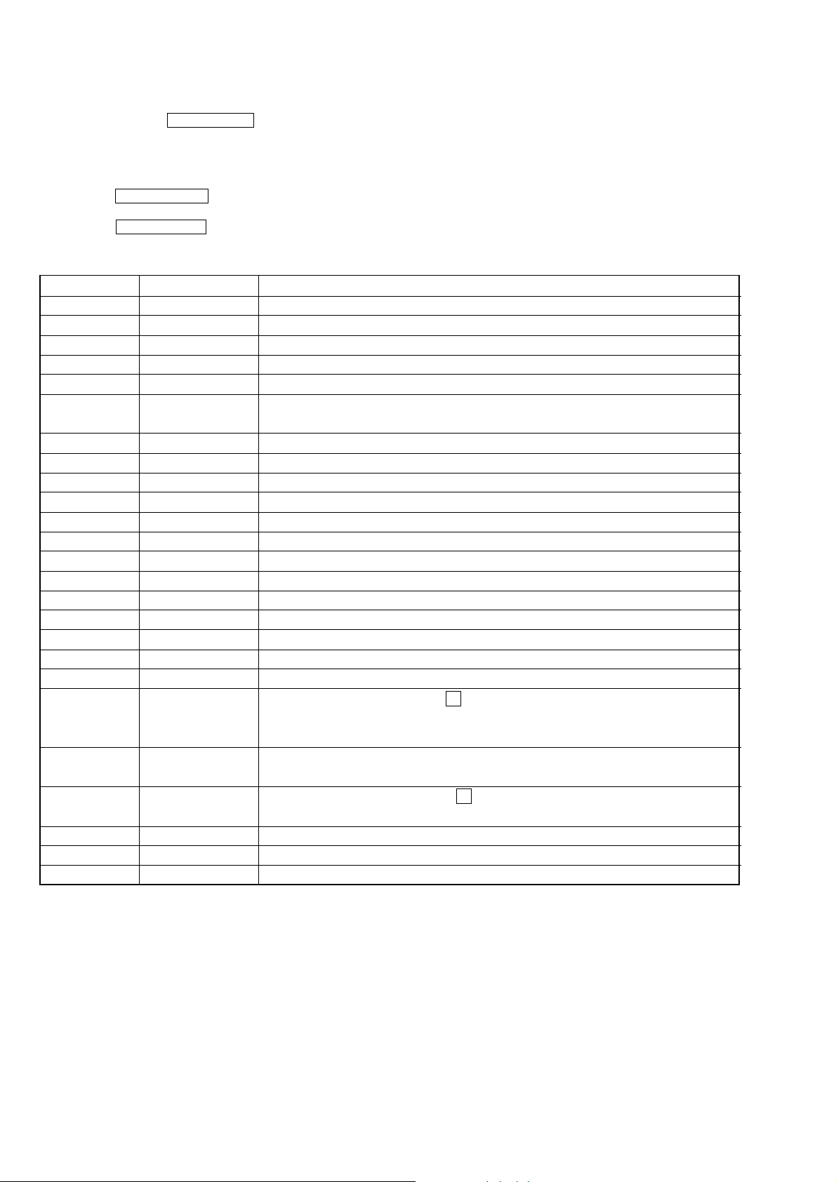
3. The Commands in Test Mode
Command No. Command name Item
12 LD ON/OFF Turn on/off the laser diode
13 SPIN ON/OFF Turn on/off the spindle motor
14 FSRV ON/OFF Turn on/off the focus servo
15 TSRV ON/OFF Turn on/off the tracking servo
16 CLV ON/OFF
17 SSRV ON/OFF Turn on/off the spindle CLV servo, when all servo of focus servo, tracking servo
18 ALL SRV ON Turn on all servo
19 ALL SRV OFF Turn off all servo
1A DISC STOP Stop the disc rotation (useful as overdrived)
24 ADJ FCSBIAS Automatically adjust the focus bias (*1)
27 FOCUS AGC Automatically adjust the focus servo gain (*1)
31 PI/FE OFSET Automatically adjust the offset signal of PI, PE and TE (*1)
45 TRACKING AGC Automatically adjust the focus servo gain (*1)
61 DISC DETECT Judge the disc type (when SA-CD, “SL” or “DL” is displayed)
7C FJUMP TEST Focus jump test mode
81 SYSTEM VERSION Display the version of system microcomputer for 2 seconds
82 I/F VERSION Display the version of IF microcomputer for 2 seconds
8D SET UP Initialization (factory set up) (AEP model) (*2)
8F SET UP Initialization (factory set up) (EXCEPT AEP model) (*2)
92 ERR CHECK Error rate display (to stop, press the x button)
93 WATER MARK WaterMark display
9D PLAY&RFD ON Measuring the jitter (to stop, press the x button)
B0 RAM clear Electric adjustment value is clear (*3)
B1 Writing Electric adjustment value is writing (*3)
B2 Check writing data Electric adjustment value is checking (*3)
*1) Not used in servicing
*2) After the all work end, set up for factory default.
*3) The Commands in Automatic Electrical Adjustments
(Use the commands When The system version number is ver1.24 and higher)
Turn on/off the spindle CLV servo, when both focus servo and tracking servo are on
and spindle servo are on
for CD display “92 C1 C2 0xff”
for SA-CD display “92 PI1 PO PI2”
display “93 xxxx” (“xxxx” is value of pspamp)
display: “9D xx 0xff 0xff” (“xx” is measuring value of jitter)
2
Page 3

SECTION 2
ELECTRICAL ADJUSTMENTS
SCD-C2000ES
GENERAL DESCRIPTION
After parts to the circuit (OPTICAL PICK-UP (DBU-3), RF
BOARD, MAIN BOARD, EEPROM (IC702), MASTERCOM
(IC705), DSP (IC706), so on) are replaced, readjusting is necessary.
Check the system software version at first, since the adjustment
procedure is different by the system software version.
Procedure:
1. ROM Version Check
Ver. 1.24 and higher before Ver. 1.23
2. U-CON Check
3. Optical Sensitive Check
3. Mode Seitting For Shipping
1. ROM Version Check
Procedure:
1. While pressing l AMS L dial and [MENU] buttons,
press the [POWER] button to turn the set on, so “DIAG MODE”
is displayed on the screen and the test mode active.
2. Select “ 81 ” by tuning l AMS L dial.
3. Press l AMS L dial, so the message is displayed the
system software version as following.
" SYS VER *.** "
4. Select “ 82 ” by tuning l AMS L dial.
5. Press l AMS L dial, so the message is displayed the I/
F version as following.
9. Push the l AMS L dial and check the “ **** ” (4
DIGITS VALUE) displayed.
Check the last value in the standard.
the standard value : 08D0 to 04D0
10. Push the Z button to open the tray.
11. Unload CD from tray.
12. Push the Z button to close the tray.
13. Press the [POWER] button to turn the set off. (Do not continue
with another test mode without power off.)
3. Optical Sensitivity Check
Setting:
MAIN board
CN702 (PIN27)
CN702 (PIN31)
CHECK DISC LIST
Use the following hybrid disc on this check.
HLXA-509 : PART No. J-6090-090-A
SACD HYBRID DISC (MARKET DISC)
Procedure:
1. Connect the oscilloscope to pin 27 and pin31 of CN702
(Main board).
2. Insert SACD hybrid disc (market disc).
3. Observe the MIRR waveform immediately after the disc
chucking is completed when disc identification is made.
At that time check that the measurement of ∆ T on the
waveform is standard.
The standard value :
7.5ms ~ 9.7ms (specification for the system
6.9ms ~ 9.7ms (specification for the system
oscilloscope
+
–
version number is Ver1.24 and higher)
version number is Ver1.23 and before)
" I/F VER *.** "
2. U-CON Check (The system version number is Ver
1.24 and higher)
This checking must be performed before any other checking.
CHECK DISC LIST
Use the following disc on this check.
SATD-S4: PART No. J-2501-184-A
SATD-S5: PART No. J-2501-215-A
Procedure:
1. While pressing l AMS L dial and [MENU] buttons,
press the [POWER] button to turn the set on.
“DIAG MODE” is displayed on the screen, so enter the test
mode.
2. Push the Z button to open the tray.
3. Load Test Disc to tray.
4. Select “ B0 ” by tuning l AMS L dial.
5. Push the l AMS L dial and check the “FFFF”
displayed.
6. Select “ B1 ” by tuning l AMS L dial.
7. Push the l AMS L dial and check the “-9” displayed.
After that the value has changed until the display shows “-0”
and lastly “****” (4 DIGITS VALUE) appears.
8. Select “ B2 ” by tuning l AMS L dial.
MIRR signal waveform
T
1V/DIV, 5ms/DIV
4. When the measurement of ∆ T is out of the standard value,
change the parts of R892 and R893 as follows and then repeat
step3 and after.
9.7 ms< ∆ t
R892/R893 120 kΩ → 110 kΩ (1-218-741-11)
∆ t< 6.9 ms
R892/R893 120 kΩ → 130 kΩ (1-218-743-11)
5. Put out the test disc from tray, then press the [POWER] button
to turn the set off.
3
Page 4

SCD-C2000ES
4. Mode Setting For Shipping ( EEPROM (IC702) on
MAIN board is replaced.)
Caution : Be sure to set the unit to the specified modes as stated in
the steps when the EEPROM (IC702) on main board is
replaced. Set the mode for shipping after ending the all
works.
Procedure:
1. While pressing l AMS L dial and [MENU] buttons,
press the [POWER] button to turn the set on.
“DIAG MODE” is displayed in the screen and set the test
mode.
2. Turn l AMS L dial, then select "8D" or "8F".
“8D” : AEP model
“8F” : EXCEPT AEP model
3. Press l AMS L dial, so “INIT START” is displayed
and Mode setting for shipping starts.
4. “INITIAL OK” appears on the display and setting end.
By this operation, the unit is initialized as follows:
PLAY MODE ALL DISCS
COMMAND MODE CD 1
REPEAT OFF
SACD/CD SACD
M/2ch MULTI
6. After 2 to 3 sec., Press the [POWER] button to turn the set off.
IC706
IC705
31
27
CN702
30
IC712
R893
R892
1
2
1-862-171-
4
Page 5

MEMO
SCD-C2000ES
5
 Loading...