


SCD-1/777ES
SERVICE MANUAL
For Technical Service
SUPPLEMENT-1
File this supplement with the service manual for technical service.
Subject: Addition and Correction
TABLE OF CONTENTS
US Model
Canadian Model
AEP Model
(ENG-99002)
1. SERVICING NOTES ............................................... 2
2. TEST MODE.............................................................. 2
3. ELECTRICAL ADJUSTMENTS......................... 3
4. DIAGRAMS
4-1. Block Diagram – RF Section – ........................................ 5
4-2. Block Diagram – SERVO Section (1/2) – ....................... 6
4-3. Block Diagram – SERVO Section (2/2) – ....................... 7
4-4. Block Diagram – MAIN Section (1/3) – ......................... 8
4-5. Block Diagram – MAIN Section (2/3) – ......................... 9
4-6. Block Diagram – MAIN Section (3/3) – ......................... 10
4-7. Block Diagram – AUDIO Section – ................................. 11
4-8. Block Diagram
– DISPLAY/KEY CONTROL Section –........................ 12
4-9. Block Diagram – POWER SUPPLY Section – ............... 13
5. ELECTRICAL PARTS LIST ............................... 14

1. SERVICING NOTES <Page 3>
• Addition
DISPLAY OF SYS ERROR
SYS ERROR: Displayed if a communication between CPU
(IC701) and display controller (IC1001) failed at
the start-up. Check the soldering of each IC and
communication lines for disconnection.
REPLACING METHOD OF ROM (IC716)
If replacing the ROM, shift the ROM socket toward the arrow
direction marked on the socket, then remove the ROM by hand.
Do not touch the optical block when replacing the ROM.
2. TEST MODE <Page 11>
• Addition
(ADJUSTMENT-1 MODE)
Entering a command in the Adjustment-1 mode in other than the
specified order could damage the optical block. Do not enter the
command except for making electrical adjustment or the following check.
1. Disc type check
After setting a disc, enter code 30. The type of disc is displayed.
2. Focus check
Press the FILTER key without setting a disc. Check the laser
emission of the pickup for SACD and the focus searching.
Then, press the SACD/CD key to check the laser emission of
the pickup for CD and the focus searching.
3. Tilt operation check
Enter code 22 without setting a disc. Then, enter code 23 or
24. After entering the code, check that the tilt motor runs a
little.
4. Sled operation check
Press the NEXT key and check that the sled motor runs a little
and the optical block moves outward a little.
Inward movement can also be checked with the PREV key,
unless the optical block is not at the most inward track.
5. Check of focus, tracking, spindle, and sled servos
Set a disc and enter code 30 to check the disc type. Then, enter
code 01, 02, 04, 05, 06, and 07 in this order. In such a case, the
codes should be entered at a certain interval so that each servo
circuit operates surely.
2
3. ELECTRICAL ADJUSTMENT
<Page 12>
• Addition
Details of IC on RF or MAIN Board:
Board Ref.No.
RF IC001 (RF amp)
MAIN IC504 (F/T driver), IC505 (Tilt driver),
IC512 (Servo DSP), IC702 (ARP), and
IC735 (EEPROM)
Adjustment Procedure
When part is not replaced:
1. S curve check
2. Traverse check
3. RF level check
4. CLV jitter check
5. Optical pick-up height adjustment
6. Overall adjustment
When Optical pick-up block is replaced:
1. Optical pick-up height adjustment
2. Overall adjustment
3. S curve check
4. Traverse check
5. RF level check
6. CLV jitter check
<Page 13>
• Correction
(S Curve check) ! : Indicates corrected portion.
INCORRECT CORRECT
Specified Value:
Disc AB
SATD-S2
TCD-784
<Page 14>
1.5 to 2.3 Vp-p - 0.1 to + 0.1 V
Specified Value:
Disc AB
SATD-S2 1.5 to 2.7 Vp-p
TCD-784 1.5 to 2.3 Vp-p
• Correction
(Optical Pick-up Height Adjustment) ! : Indicates corrected portion.
INCORRECT CORRECT
Procedure:
11. Lock the OP height adjusting screw 1 when adjustment finished.
12. Press the
13. Press the ! button to turn the power off.
x button
Procedure:
11. Lock the OP height adjusting screw 1 when adjustment finished.
12. Lock the OP height adjusting screw 1 at screw lock.
$
13. Press the x button
14. Press the ! button to turn the power off.
^
- 0.1 to + 0.1 V
3

<Page 15>
• Correction
(Overall Adjustment) ! : Indicates corrected portion.
INCORRECT CORRECT
Thresholds for Overall Adjustment
NO. Description U limit L limit
00 PI Level SL 0 4
01 PI Level DL 7
• Addition
The example of thresholds for overall adjustment:
On No. 22 Focus Bias CD, the specified value is from E0 to 20. Therefore, values like E9, FF, 03, 15 are within the specified value.
Thresholds for Overall Adjustment
NO. Description Low limit Upper limit
00 PI Level SL 0 4
01 PI Level DL 7
^
^
4
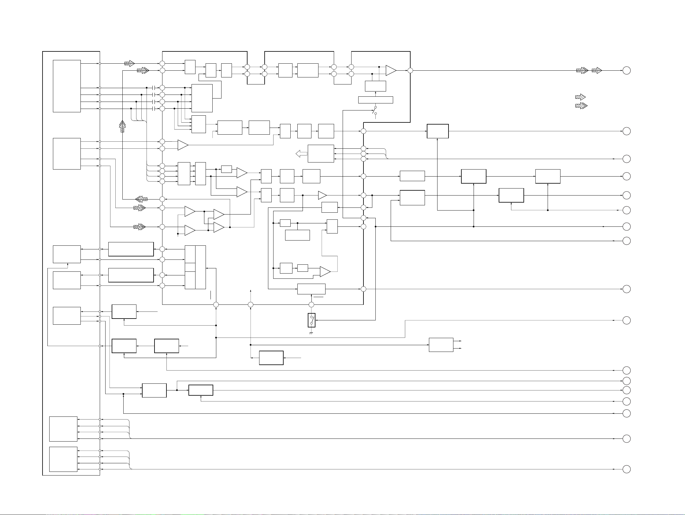
4. DIAGRAMS
4-1. BLOCK DIAGRAM – RF Section –
SCD-1/777ES
DETECTOR
(FOR SACD)
DETECTOR
(FOR CD)
OPTICAL PICK-UP
BLOCK
(KHS-180A/J1N)
LASER DIODE
(FOR SACD)
LASER DIODE
(FOR CD)
SKEW
SENSOR
RFP
CDE
CDF
PD1
PD2
DVD LD
PD
CD LD
MON
LED
SKEW OUT
SKEW IN
DVDRFP
1
CDRF
63
A
B
C
D
AUTOMATIC POWER
CONTROL (FOR SACD)
Q004
AUTOMATIC POWER
CONTROL (FOR CD)
Q002
B+ SWITCH
Q007
5
6
7
8
16
15
14
13
12
11
64
3
4
22
21
24
23
D+5V
A2
B2
C2
D2
E
F
A
B
C
D
CDRFDC
PD1
PD2
DVDLD
DVDPD
CDLD
CDPD
MUX
+
–
L.P.F.,
GCA
–
+
–
+
VC
DVD
CD
SUMMING
AMP
GCA,
EQ
AMP
SUMMING
APC
MUX
VC
+
–
+
+
LDON
25 27
ATOP
ATT
ATON
COMPARATOR
GCA
62
61
DETECTOR
+
–
+
+
VCI
AIP
INPUT
59
60
PHASE
MUX
MUX
BIAS,
AIN
AGC
SACD / CD RF AMP,
FOCUS/TRACKING ERROR AMP
MUX
L.P.F.,
AGC
L.P.F.
AGC
TOP
HOLD
IC001
AGC CHARGE
PUMP
DEFECT
SWITCH
PROGRAM-
MABLE
EQ FILTER
L.P.F.,
GCA
SERIAL PORT
OFFSET
CANCEL
DAC
PEAK/BOTTOM
HOLD
32
Q2
FNP
FNN
OFFSET
CANCEL
REGISTER
INPUT
BUFFER
MUX
COMPARATOR
+
–
FDCHG
52
51
DIP
53
DIN
54
AGC CHARGE PUMP
FULL WAVE
RECTIFIER
SIGO
57
DSDRF
1
(Page 8)
• SIGNAL PATH
: SACD
: CD
SELECT
SWITCH
IC007 (1/2)
SELECT
SWITCH
IC007 (2/2)
SELECT
SWITCH
IC011 (1/2)
SELECT
SWITCH
IC011 (2/2)
SSIDT, SSICK, SDEN
FDWN
PIOFS
LDON
DFCTB
MIRR
TE
FE
PI
2
(Page 6)
3
(Page 6)
4
(Page 6)
5
(Page 6)
6
(Page 7)
7
(Page 6)
8
(Page 7)
9
(Page 6)
10
(Page 7)
SDATA
SCLK
SDEN
MIN
HOLD1
DFT
MIRR
TE
41
SSIDT
47
SSICK
46
SDEN
48
FE
42
PI
36
35
49
37
29
FE GCA
IC006 (2/2)
PI OFSET
CANCEL
IC006 (1/2)
TRACKING COIL
TRACKING COIL
05
2-AXIS DEVICE
FOCUS/
(FOR SACD)
2-AXIS DEVICE
FOCUS/
(FOR CD)
VLD
DVD FCS+
DVD FCS–
DVD TRK+
DVD TRK–
CD FCS+
CD FCS–
CD TRK+
CD TRK–
B+ SWITCH
Q003
DSDF+
DSDF–
DSDT+
DSDT–
CDF+
CDF–
CDT+
CDT–
B+ SWITCH
TILT ERROR
AMP
IC003, 004
Q008, 009
RF+5V
GCA
IC012, Q006
VC BUFFER
IC002, 005
RF+5V
DVC/AVC
BUFFER
IC508
DCV
ACV
SLOUTS
TILT/H
TIOFS
DSDF+, DSDF–,
DSDT+, DSDT–
CDF+, CDF–,
CDT+, CDT–
TIERR
TIE
11
12
13
14
15
(Page 6)
16
(Page 6)
17
(Page 6)
(Page 7)
(Page 7)
(Page 7)
(Page 7)
55

SCD-1/777ES
4-2. BLOCK DIAGRAM – SERVO Section (1/2) –
17
(Page 5)
16
(Page 5)
4
(Page 5)
2
(Page 5)
9
MUTE1
CDF+
CDF–
CDT+
CDT–
DSDF+
DSDF–
DSDT+
DSDT–
FE
TE
14
DO1+
13
DO1–
12
DO2+
11
DO2–
15
DO4+
16
DO4–
17
DO3+
18
DO3–
SACD/CD
FOCUS/TRACKING
COIL DRIVE
IC504
IN1–
IN2–
IN4–
IN3–
MUTE2
3
6
26
23
20
MUTING
Q506
BUFFER
IC1503
MUTING
Q507
TE GCA
IC509 (2/3)
SWITCHING
IC520
BUFFER
IC1502
FE GCA
IC509 (3/3)
SWITCH
IC519
COMPARATOR
IC510, 511 (2/2)
1
46
49
2
26
24
89
ICDDVD
FOUT
TOUT
CDDVD
FE
TE
TZC
SERVO
DIGITAL SIGNAL
PROCESSOR
IC512 (1/3)
TRST
84 18
RS
94
ERROR
98
100
FON
SRVRST
22
ERROR
25
FON
21 TEAGC1
EXPANDER
IC712 (1/3)
(Page 5)
5
(Page 5)
7
(Page 5)
9
15
(Page 5)
3
(Page 5)
DFCTB
PI
MIRR
TIOFS
SSIDT, SSICK, SDEN
05
COMPARATOR
IC511 (1/2)
SWITCHING
IC521
PI
ERROR AMP
IC509 (1/3)
AVC
+2.5V
REGULATOR
8
IC513
20 TEAGC2
SDEN
PI
21
4
BUSY
DFCT
7
MIRR
88
TIOFS
73
VRTA
28
VRT3
37
VRT2
42
VRT1
+3.75V
7
1
+1.25V
45
VRT0
50
VRBA
34
VRB3
36
VRB2
43
VRB1
44
51
VRB0
ACK
X2/CLKIN
3
SSIDT
SSICK
65
IC514, 728
59 SDEN
82 PLIN
79 BUSY2
89 SDACK
2 SSSD
3 SSICLK
CPU
IC701 (1/4)
27M
18
(Page 8)
66

SCD-1/777ES
4-3. BLOCK DIAGRAM – SERVO Section (2/2) –
PIOFS
8
(Page 5)
GATE SWITCH
GATE SWITCH
SWITCH
Q508
13
(Page 5)
12
(Page 5)
(LOADING)
TIERR
TIE
M
M1
M
M3
(TILT)
M
M2
(SLED)
LODING MOTOR
DRIVE
IC515
TILT MOTOR
DRIVE
IC505
TILT
COMPARATOR
IC506
SLED MOTOR
DRIVE
IC503
DVC
IC517
IC516
DVC
IC522
SWITCHING
IC507
COM
1
CH1
6
7 5
CH0
GATE SWITCH
A
IC777
IC1651, Q1651, 1653
SLED ERROR
AMP
S003
(LOAD OPEN)
S004
(LOAD CLOSE)
SWITCH
Q1652
19
10
9
4
5
53
26
51
58
PISEL
LINLOAD
LOAD
LDSW1
LDSW0
TILTOUT
TIUNLK
SDPREK
SLDDLY
4
95
PWM
RSTOUT
CPU
IC701
(2/4)
11
(Page 5)
SLOUTS
SLED FG SENSOR
IC008
STABILIZER
DETECT SENSOR
D002, IC009
M7
SPINDLE
MOTOR
STABILIZER
Q501, 502
1
WIN2
34
WIN1
33
VIN2
32
VIN1
31
UIN2
30
UIN1
29
VH+
28
VH–
19
WOUT
22
VOUT
23
UOUT
DRIVE
SPINDLE
MOTOR DRIVE
IC501
IC010
SPCL1
SPGC2
SPGC1
HFG
SLMUTE
SLDSW1
SLDSW0
STBLDTC
STBLDRV
SPCTL1
SPGC2
SPGC1
EXPANDER
IC712 (2/3)
96
TKC
HFG
97
MDSO, MDPO
19
(Page 8)
38
SDCONT
14
TKC
8
10
11
27
VC
13
Z2
14
15
Z1
SPINDLE
ERROR AMP
IC502
MDSO
MDPO
SOUT
S002
(SLED IN)
41
SERVO DIGITAL
SIGNAL PROCESSOR
IC512 (2/3)
(SLED OUT)
GATE SWITCH
IC716
S001
60
6
7
1
11
12
14
15
6
(Page 5)
10
(Page 5)
14
(Page 5)
FDWN
LDON
TILT/H
05
50
52
57
FCSDWN
SACDLDON
TILT/H
77

SCD-1/777ES
4-4. BLOCK DIAGRAM – MAIN Section (1/3) –
1
(Page 5)
DSDRF
RF BUFFER
EXPANDER
IC711
(1/3)
IC721
WMGC0
WMGC1
WADCE
LOCK
NORF
DFCT
MUTE
MD2
FWON
SWITCHING
11
12
9
26
25
22
20
19
18
IC739
D-RAM
IC707
RF AMP
IC722
DQ0
DQ15
UCAS
LCAS
ı
RAS
A0
ı
A9
WE
OE
29
ADIN
5
XCE
A/D CONVERTER
21
ı
24
27
ı
32
41
2
ı
ı
44
5
46
7
ı
ı
49
10
17
33
18
34
35
IC708
D7
D0
CLK
10
RFIN1
12
RFIN2
9
ı
ı
16
GATE SWITCH
18
IC720
2
PCKO
ARP
IC702
(1/2)
53
LOCK
51
NORF
50
DFCT
110
MUTE
112
MD2
55
FWON
145
137
ı
ı
MA0
147
139
ı
149
141
MA9
ı
143
166
156
ı
ı
MD0
169
159
ı
171
161
MD15
ı
ı
174
164
150
XMWR
154
XOE
153
XRAS
151
XCAS
RFD
SD0
SD7
SDCK
XSHD
XSRQ
XSAK
SDEF
DATA
BCLK
4
96
ı
99
ı
101
ı
104
90
91
92
93
94
106
107
IC724 (2/2)
IC724 (1/2)
GATE SWITCH
IC750
GATE SWITCH
IC719
100
101
DSD DECODER
IC703 (1/2)
82
WAD0
ı
ı
89
WAD7
• SIGNAL PATH
: SACD
: CD
: DIGITAL OUT
80
WCK
81
WRFD
91
SD7
ı
ı
98
SD0
5
SDCK
2
XSHD
1
XSRQ
XSAK
SDEF
DSAR
DSAL
BCKA
LRCK
MCKI
48
47
46
19
PLL
IC715
14
4
2
3
6
8
7
INVERTER
IC725
16
18
17
14
12
13
TRANS MITTER
IC772
TRANS MITTER
IC773
TRANS MITTER
IC771
TRANS MITTER
IC770
SDATAR
SDATAL
SBCK
CODATA
CDBCK
REFLRCK
SDATAL,
SDATAR,
SBCK
CDDATA,
CDBCK,
REFLRCK
20
(Page 11)
21
(Page 11)
19
(Page 7)
18
(Page 6)
MDSO, MDPO
27M
MDSO
MDPO
05
43
MDSO
48
MDPO
IC729 (2/3)
122
MCKI
124
SCKI
23
CKO33
16
CKO27
DIVIDER
IC710
CK27
18
DOUT
LRCK
CK33
LCXO
DCXO
109
PLL
108
IC729 (1/3)
25
34
37
PLL
IC713
IC714
IC729
(3/3)
A0
A10
DQ0
DQ7
DOUT
22
51
52
55
ı
ı
63
70
ı
ı
77
66
67
68
69
9
ı
A0
13
ı
16
A10
ı
21
2
ı
5
24
ı
27
6
23
7
22
DQ0
DQ7
WE
CAS
RAS
OE
D-RAM
IC709
ı
(Page 10)
88

4-5. BLOCK DIAGRAM – MAIN Section (2/3) –
SERVO DIGITAL
SIGNAL PROCESSOR
IC512 (3/3)
CPU
IC701 (3/4)
SCD-1/777ES
HO0/HD0-HO6/HD6
HIO/HD7
56–63 18–21, 23–24
HCK/XHLBS
HR/XHRD
72
HFS/XHWR
70 71 89 70 71 72 9963
GATE SWITCH
IC736
GATE SWITCH
IC737
SDSCS RD HWR LWR RES
RESET SIGNAL
GENERATER
IC734
DIG+5V
D0–D15
DATA BUS
A0–A18
36-43, 45-55
ADDRESS BUS
A21 A22 A20
1 2 6
ABG1
SWITCHING
IC775
Y5 Y4
10 11
87 58 91 9098 100
ARPINT
WAIT
CS0 CS1
28–30,
33–37
D0–D7
05
44–46
A0–A2
EXPANDER
IC712
(3/3)
39 41 42 43
XRD
XDIS
XWR
XCS
28–30,
33–37
D0–D7
44–46
A0–A2
EXPANDER
IC711
(2/3)
39 41 42 43
XCS
XRD
XDIS
XWR
ARPRST XRST
21 84
59–62,
64–67
D0–D7
GATE
SWITCH
IC778
70–73,
75–78
A0–A7
ARP
IC702
(2/2)
56 57 80 81
XRD
XINT
XWR
XCS
83
XWAT
3, 4–11,
34–42
A0–A17
15–22,
24–31
DQ0–DQ15
FLASH MEMORY
IC716
12 14 43
CE
OE
1–4, 7, 10–16,
WE
17–20, 31
A0–A16
21–23,
25–29
IO/1–IO/8
S-RAM
IC717
5 30 32
WE
CE1
1–4, 7, 10–16,
OE
17–20, 31
A0–A16
21–23,
25–29
IO/1–IO/8
S-RAM
IC718
5 30 32
WE
CE1
OE
RESET
23
(Page 12)
99
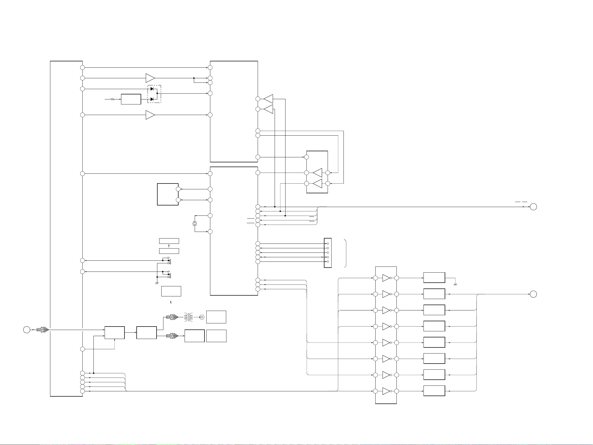
SCD-1/777ES
4-6. BLOCK DIAGRAM – MAIN Section (3/3) –
10 41
TEST
SHR RST
13 13
SHR MUTE
14
DRST
SHR LT
15 7
INVERTER
Q705
IC726 (1/4)
D702
IC726 (4/4)
DSD DECODER
IC703 (2/2)
TESTI
XRST
TRST
22
8
9
10
11
IC726 (2/4)
IC726
(3/4)
BUS
TRANSCEIVER
IC730
1912
XOE
6
SMUT
MSCK
MSDI
MSDO
MSREDY
XMSDOE
22
(Page 8)
DOUT
EXPANDER
IC711
(3/3)
AK0
62 83
SDA
S713
CUSTOM
S171
COMMAND
MODE
CD1
CD2
67SCL
16MHz
X701
T991
OPTICAL
TRANSCEIVER
IC991
EEPROM
IC735
STANDARD
27FIL SET
47REM CODE
TX SELECT
SWITCH
IC732
61DOCTRL
WAVE
SHAPER
IC990
AK0
60
EEP SCL
59
EEP SIO
66
EXTAL
67
XTAL
J990
DIGITAL OUT
(CD)
COAXIAL
DIGITAL OUT
(CD)
OPTICAL
CPU
IC701 (4/4)
93 3
SHR RDY
13
SOUT1
15
SIN1
17
SCK1
81
IFBSY
94
IFREQ
12
SOUT0
14
SIN0
78
AN0
5
JIG CTR
16
SCK0
6
DFLT
8
DATA
9
SHIFT
2 18
DFLT
DATA
SHIFT
SOUT
SIN
SCK
ACK
REQ
DFLT
SHIFT
17
CN707
1
2
3
5
7
TXD
RXD
DIAGN
CTS
JIG CLK
(RS-232C)
XLRCTRL
FICTRL
AMUT
DFINT
BUS BUFFER
IC727
2 18
3 17
4 16
5 15
6 14
7 13
TRANSMITTER
IC760
TRANSMITTER
IC761
TRANSMITTER
IC762
TRANSMITTER
IC763
TRANSMITTER
IC764
TRANSMITTER
IC765
FILCTRL
AMUTZ
INIT
LATCH
SHIFT
SOUT, SIN, SCK,
ACK, REQ
(Page 12)
FILCTRL, AMUTZ,
INIT, LATCH, SHIFT,
DATA, MODE
(Page 11)
24
25
53MODE
52DF INIT
54A FIL
57A MUTE
58XLRON
05
MODE
DFINT
FILCTRL
AMUT
XLRCTRL
DATA
MODE
8 12
9 11
TRANSMITTER
IC766
TRANSMITTER
IC767
DATA
MODE
1010

4-7. BLOCK DIAGRAM – AUDIO Section –
CDDATA
CDBCKI
REFLRCK
SDATAR
SDATAL
SBCK
AMUTZ
FILCTRL
INIT
LATCH
SHIFT
SCDATA
MODE
28
NREGCLR
30
INIT
31
LATCH
32
SHIFT
33
SCDATA
34
MODE
48
DATAI
49
BCKI
50 LRCK
52
SDATAR
53
SDATAL
51 SBCK
DIGITAL FILTER
IC301
NSDOL4
NSDOL3
NSDOL2
NSDOL1
NSDOR4
NSDOR3
NSDOR2
NSDOR1
DINT
XIN
64FSI
1
3
6
8
24
22
19
17
40
13
10
25
(Page 10)
21
(Page 8)
20
(Page 8)
49
48
47
46
36
37
38
39
50
33
40
NSDIL4
NSDIL3
NSDIL2
NSDIL1
NSDIR4
NSDIR3
NSDIR2
NSDIR1
MUTE
LVCKO1
64FSO
D/A CONVERTER
IC302
L1+
L1–
L2+
L2–
R1+
R1–
R2+
R2–
XIN
256FSO
SCD-1/777ES
• SIGNAL PATH
SWITCHING
Q302
SWITCHING
Q304
CURRENT PULSE
IC101
CIREF
1615
CS
IO1+
IO2–
IO1–
IO2+
1
2
4
5
REGULATOR
CONTROL
SWITCH
62
60
2
4
22
24
18
16
10
35
R-CH
X301
45MHz
IN2+
27
IN2–
28
25
IN1+
24
IN1–
Q109
RELAY DRIVE
PHD302, Q303
BUFFER
IC102
REGULATOR
AMP
IC107
R338
MIX AMP
IC103
+5V
RELAY DRIVE
PHD301, Q301
R-CH
RY102
RY101
LOW-PASS
FILTER
IC108, RY101 (1/2)
(SCD-1)
LOW-PASS
FILTER
IC109, RY101 (2/2)
R303
LINE AMP
IC104, RY102
BUFFER AMP
Q101-Q108
RY150
RY171
R-CH
J250
LINE OUT
(ANALOG)
UNBALANCED
J150
R
L
(SCD-1)
: SACD
: CD
LINE OUT
(ANALOG)
(SCD-777ES)
05
SBCK
REFLRCK
51
SBCKI
50
LRCKI
TRANSMITTER
PHD304
TRANSMITTER
PHD303
8 9
11 12
6 5
3 2
GATE SWITCH
IC305
COUNTER
IC306, 307
S170
BALANCED
OUT
ON
OFF
J170
BALANCE
CONVERTER
IC171
B+
RY170
R-CH
BALANCE
CONVERTER
IC271
RY271
2
2
1
3
LINE OUT
(ANALOG)
BALANCED
1
3
J270
L
R
1111

SCD-1/777ES
4-8. BLOCK DIAGRAM – DISPLAY/KEY CONTROL Section –
23
(Page 9)
24
(Page 10)
RESET
SCK, SIN, SOUT,
ACK, REQ
SCK
SIN
SOUT
ACK
REQ
30
RESET
RESET-OUT
48
SCK
49
SIN
50
SOUT
47
ACK
60
REQ
46
51
CP
52
CS
53
DA
FL DRIVER
IC1002
RESET
67
69
CP
68
CS
70
DA
66
OOSC1
21P
28P
31P
34P
35P
22P
27P
32P
33P
3
1P
ı
ı
23
30
ı
ı
33
36
37
24
ı
ı
29
34
35
SEGMENT
DRIVE
Q1001-1008
P1-P21, P28-P31,
P34, P35
P22-P27,
P32, P33
FL1001
FLUORESCENT
INDICATOR
TUBE
X1001
8MHz
BP
(TEST MODE)
31
32
42
EXTAL
XTAL
TEST
FL CONTROLLER,
KEY CONTROL,
LED DRIVE
IC1001
LED
(SACD)
LED
(CD)
LED
(PLAY)
LED
(PAUSE)
KE0
C1004,
OSC
R1034
65
OSC0
64
65
66
67
44
LED DRIVE
Q1021
LED DRIVE
Q1022
LED DRIVE
Q1023
LED DRIVE
Q1024
S1001-1005
D1001
SACD
D1002
CD
D1003
D1004
15G
16G
19G
39
1G
ı
ı
53
54
ı
ı
57
GRID DRIVE
Q1009-1012
1G-15G
16G-19G
RECIEVER
IC1003
S1006-1011
45
KE1
56SIRCS
05
REMOTE CONTROL
1212

4-9. BLOCK DIAGRAM – POWER SUPPLY Section –
SCD-1/777ES
DNMUTEZ
+5V
DIGITAL FILTER
(IC301) B+
+7V
CURRENT PULSE
(IC101, 201) B+
+5V
D/A CONVERTER
(IC302) B+
+5V
AUDIO CIRCUIT
B+
+9V
REGULATOR AMP
(IC107, 207) B+
–9V
REGULATOR AMP
(IC107, 207) B–
–7V
CURRENT PULSE
(IC101, 201) B–
AUDIO CIRCUIT
B+
AUDIO CIRCUIT
B–
+7V
REGULATOR
IC105, 205
+5V
REGULATOR
IC304, 308
+5V
REGULATOR
IC309
–7V
REGULATOR
IC106, 206
REGULATOR
Q401, 403, 405, 407,
409, 411, 413, 415, 417
REGULATOR
Q402, 404, 406, 408,
410, 412, 414, 416, 418
R429
+5V
REGULATOR
IC401
+9V
REGULATOR
IC402
–9V
REGULATOR
IC403
RECT
D408, 409
RECT
D406
RECT
D407
RECT
D403, 404,
410, 411
POWER
TRANSFORMER
(ANALOG)
T401
F481
LINE FILTER
T481
S409
(POWER)
CN480
~AC IN
(US, Canadian)
(AEP)
D–30V
DG–30V
MOT+12V
A+5V, D+5V,
RF+5V, DIG+5V
A+3.3V
+3.3V
PLL (IC715) B+
DRST
ARP+3.3V
DIG+3.3V
F+
F–
–30V
D451
+3.3V
REGULATOR
IC740
+3.3V
REGULATOR
IC741
05
REGULATOR
Q451
+12V
REGULATOR
IC451
+5V
REGULATOR
IC452
+3.3V
REGULATOR
IC453
D453
D452
R458
R456
RECT
D454
RECT
D455
RECT
D457, 458
RECT
D456
F451
F452
F453
POWER
TRANSFORMER
(DIGITAL)
T451
LINE FILTER
T482
1313

5. ELECTRICAL PARTS LIST
Page Before Change After Change
Ref. No. Part No. Description Remark
(MAIN BOARD, COMPLETE)
69
IC703 8-752-400-62 IC CXD2750AQ
IC716 (NOT SUPPLIED) IC MBM29F400TC-90PF
Ref. No. Part No. Description Remark
IC703 8-752-400-60 IC CXD2751Q
IC716 8-759-663-89 IC MBM29F400TC-90PF-S23
SCD-1/777ES
9-929-012-82
1414
Sony Corporation
Home Audio Division Company
Printed in Japan C 1999. 12
99L0503-1D
Published by Quality Assurance Dept.
 Loading...