

Page 1
SERVICE MANUAL
LJ-2T
CHASSIS
MODEL MODEL
RM-Y980
KL-W7000
RM-Y980USCanadian
KL-W7000
CHASSIS No. CHASSIS No.COMMANDER DEST. COMMANDER DEST.
SCC-N56B-A
KL-W9000
SCC-N56B-A
KL-W9000
RM-Y980
RM-Y980USCanadian
SCC-N56A-A
SCC-N56A-A
MICROFILM
Please file according to model size...
*
37
50
KL-W7000 KL-W9000RM-Y980
LCD PROJECTION DATA MONITOR
Page 2

KL-W7000/W9000
RM-Y980
Specifications
Acceptable signal NTSC video signal, RGB signal
(For details, see page 9.)
Projection system 3 LCD panels, 1 lens projection
system
LCD panel 1.35-inch TFT LCD panel
Approx. 1.54 million dots
(512,880 pixels)
1068.5 × 480 dots × 3 panels
Lamp XL-100U: HID lamp, 100 W
Lens Large diameter hybrid lens F2.4
Screen size (measured diagonally)
KL-W7000: 37 inches (942 mm)
KL-W9000: 50 inches (1,272 mm)
Viewable image size (for RGB input)
KL-W7000: Approx. 36.3 inches
(921 mm) (diagonally)
Approx. 803 × 452 mm (w/h)
KL-W9000: Approx. 49.1 inches
(1247 mm) (diagonally)
Approx. 1087 × 611 mm (w/h)
Deflection frequency
Horizontal: 31.5–48 kHz
Vertical: 50–85 Hz
Inputs/outputs
VIDEO 1, 2 and 3 IN
VIDEO OUT
S VIDEO (VIDEO 1, 3 IN only)
(4-pin mini-DIN):
Y: 1 Vp-p, 75 ohms
unbalanced, sync negative
C: 0.286 Vp-p (burst signal), 75
ohms
VIDEO (phono jacks):
1 Vp-p, 75 ohms unbalanced,
sync negative
AUDIO (phono jacks):
2 channels, 500 mVrms
Impedance: more than 47
kohms
S VIDEO (4-pin mini-DIN):
Y: 1 Vp-p, 75 ohms
unbalanced, sync negative
C: 0.286 Vp-p (burst signal), 75
ohms
VIDEO (phono jacks):
1 Vp-p, 75 ohms unbalanced,
sync negative
AUDIO (phono jacks):
2 channels, 500 mVrms
Impedance: less than 5 kohms
RGB 1, 2 IN
VIDEO (D-sub 15-pin, female):
R, G, B: 0.7 Vp-p, positive, 75
ohms terminated
Sync on Green: 0.286 Vp-p
SYNC/HD: Composite sync:
TTL, high impedance,
sync positive/negative
Horizontal sync: TTL, high
impedance, sync positive/
negative
VD: Vertical sync: TTL, high
impedance, sync positive/
negative
AUDIO (RGB 1 IN) (phono
jacks)
2 channels, 500 mVrms
Impedance: more than 47
kohms
AUDIO (RGB 2 IN) (stereo
minijack)
500 mVrms
Impedance: more than 47
kohms
Power requirement
100 to 120 V AC, 50/60 Hz
Power consumption
190 W (MAX)
Standby mode: 2 W
Dimensions KL-W7000: 920 x 825 x 390 mm
(36
1
/
4
× 32
1
/
2
× 15
3
/8 inches)
(w/h/d)
KL-W9000: 1,228 × 1,055 × 565
mm (48
3
/
8
× 41
5
/
8
× 22
1
/
4
inches) (w/h/d)
Mass KL-W7000: Approx. 30 kg
(68 lbs 2 oz)
KL-W9000: Approx. 43 kg
(106 lbs 8 oz)
Supplied accessories
Remote control RM-Y980 (1)
Size AA (R6) batteries (2)
AC power cord (1)
RGB signal cable (D-sub 15-pin
˜ D-sub 15-pin) (1)
HD15-HD15 (male, without the
No. 9 pin) adaptor (1)
Macintosh adaptor (1)
Windows 95 Monitor
Information Disk (1)
Brackets (2)
Screws for brackets (2)
Buckle (1)
Hexagon head wrench (1)
Dust remover (1)
Optional accessories
Lamp unit XL-100U
Design and specifications are subject to change
without notice.
– 2 –
Page 3
SAFETY CHECK-OUT
(US Model only)
KL-W7000/W9000
RM-Y980
After correcting the original service problem, perform the following safety checks before releasing the set to the customer:
1. Check the area of your repair for unsoldered or poorly-soldered connections. Check the entire board surface for solder
splashes and bridges.
2. Check the interboard wiring to ensure that no wires are
“pinched” or contact high-wattage resistors.
3. Check that all control knobs, shields, covers, ground straps,
and mounting hardware have been replaced. Be absolutely
certain that you have replaced all the insulators.
4. Look for unauthorized replacement parts, particularly transistors, that were installed during a previous repair. Point them
out to the customer and recommend their replacement.
5. Look for parts which, though functioning, show obvious signs
of deterioration. Point them out to the customer and recommend their replacement.
6. Check the line cords for cracks and abrasion. Recommend the
replacement of any such line cord to the customer.
7. Check the condition of the monopole antenna (if any).
Make sure the end is not broken off, and has the plastic cap on
it. Point out the danger of impalement on a broken antenna to
the customer, and recommend the antenna’s replacement.
8. Check the B+ and HV to see if they are specified values. Make
sure your instruments are accurate; be suspicious of your HV
meter if sets always have low HV.
9. Check the antenna terminals, metal trim, “metallized” knobs,
screws, and all other exposed metal parts for AC Leakage.
Check leakage as described below.
To Exposed Metal
Parts on Set
LEAKAGE TEST
The AC leakage from any exposed metal part to earth ground
and from all exposed metal parts to any exposed metal part having a
return to chassis, must not exceed 0.5 mA (500 microampers).
Leakage current can be measured by any one of three methods.
1. A commercial leakage tester, such as the Simpson 229 or
RCA WT-540A. Follow the manufacturers’ instructions to
use these instruments.
2. A battery-operated AC milliammeter. The Data Precision 245
digital multimeter is suitable for this job.
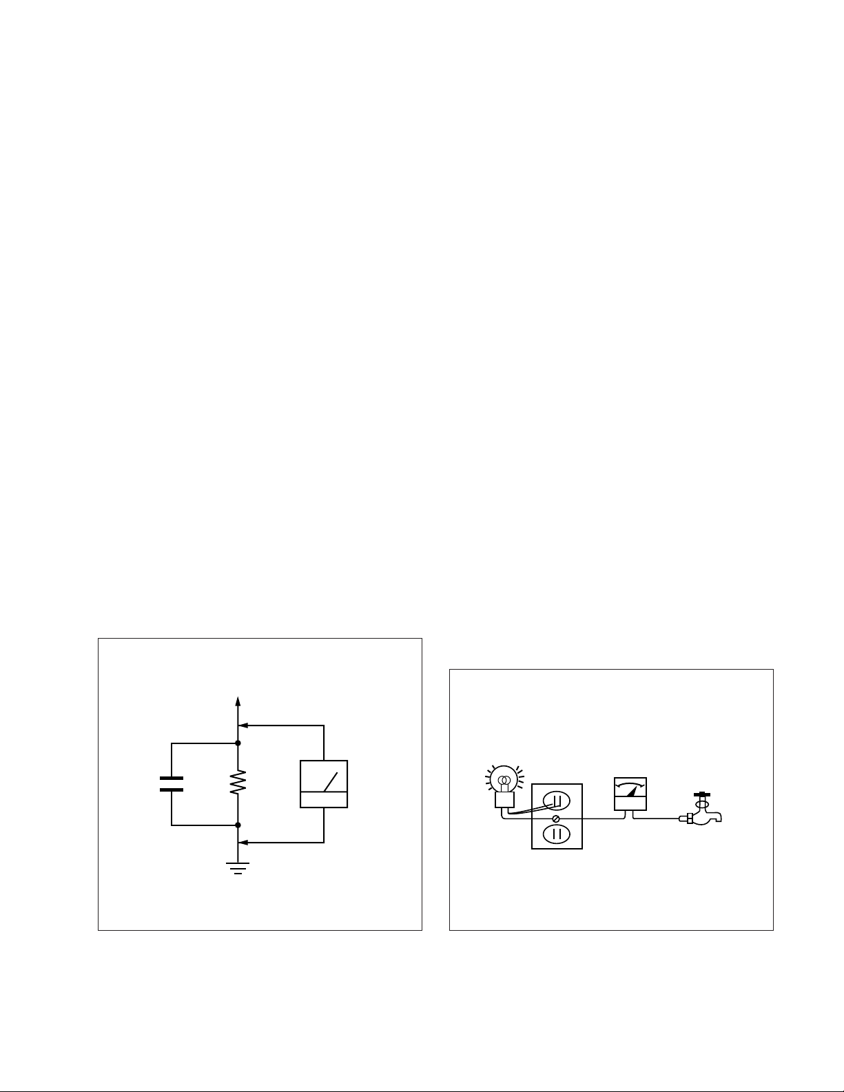
3. Measuring the voltage drop across a resistor by means of a
VOM or battery-operated AC voltmeter. The “limit” indica-
tion is 0.75 V, so analog meters must have an accurate low-
voltage scale. The Simpson 250 and Sanwa SH-63Trd are ex-
amples of a passive VOMs that are suitable. Nearly all battery
operated digital multimeters that have a 2 V AC range are suit-
able. (See Fig. A)
HOW TO FIND A GOOD EARTH GROUND
A cold-water pipe is guaranteed earth ground; the cover-plate
retaining screw on most AC outlet boxes is also at earth ground. If
the retaining screw is to be used as your earth-ground, verify that it
is at ground by measuring the resistance between it and a coldwater pipe with an ohmmeter. The reading should be zero ohms. If
a cold-water pipe is not accessible, connect a 60 – 100 watts
trouble light (not a neon lamp) between the hot side of the receptacle and the retaining screw. Try both slots, if necessary, to locate
the hot side of the line, the lamp should light at normal brilliance if
the screw is at ground potential. (See Fig. B)
0.15 µF
1.5 k
Ω
Earth Ground
AC
Voltmeter
(0.75 V)
Fig. A. Using an AC voltmeter to check AC leakage.
– 3 –
Trouble Light
AC Outlet Box
Ohmmeter
Fig. B. Checking for earth ground.
Cold-water Pipe
Page 4

KL-W7000/W9000
RM-Y980
TABLE OF CONTENTS
Section Title Page Section Title Page
1. GENERAL .................................................................. 5
2. DISASSEMBLY
2-1. Rear Cover Removal ........................................... 18
2-2. Chassis Assy Removal ........................................ 18
2-3. Service Position ................................................... 18
2-4. U Board Removal ................................................ 18
2-5 Power Block and K Board Removal ................... 19
2-6. Filter Removal ..................................................... 19
2-7. Lamp Removal .................................................... 20
2-8. HA and HB Boards Removal .............................. 20
2-9-1. Screen Frame Removal [W7000] ........................ 20
2-9-2. Screen Frame Removal [W9000] ........................ 20
2-10-1.C Board Removal ................................................ 21
2-10-2.Extension Cable (C Board) .................................. 21
2-11. Optical Unit Removal .......................................... 21
3. CIRCUIT ADJUSTMENTS ................................ 22
4. DIAGRAMS
4-1. Block Diagrams ................................................... 39
4-2. Circuit Boards Location....................................... 53
4-3. Schematic Diagrams and Printed
Wiring Boards ................................................. 54
(1) Schematic Diagrams of HA,HB, K,
TA and TB Boards ........................................... 55
(2) Schematic Diagram of A (1/3) Board ................... 63
(3) Schematic Diagram of A (2/3) Board ................... 67
(4) Schematic Diagram of A (3/3) Board ................... 71
(5) Schematic Diagram of BB Board.......................... 75
(6) Schematic Diagram of U Board ............................ 83
(7) Schematic Diagram of C (1/2) Board.................... 87
(8) Schematic Diagram of C (2/2) Board.................... 91
(9) Schematic Diagrams of G and GA Boards ............ 95
4-4. Semiconductors ................................................... 99
5. EXPLODED VIEWS
5-1. Chassis [W7000] ................................................. 101
5-2. Front Cover [W7000] .......................................... 102
5-3. Screen Mirror Block and Optics Unit [W7000] .. 103
5-4. Chassis [W9000] ................................................. 104
5-5. Front Cover [W9000] .......................................... 105
5-6. Screen Mirror Block and Optics Unit [W9000] .. 106
6. ELECTRICAL PARTS LIST ............................ 107
SAFETY-RELATED COMPONENT WARNING!!
COMPONENTS IDENTIFIED BY SHADING AND MARK
ON THE SCHEMATIC DIAGRAMS, EXPLODED VIEWS
AND IN THE PARTS LIST ARE CRITICAL TO SAFE
OPERATION. REPLACE THESE COMPONENTS WITH
SONY PARTS WHOSE PART NUMBERS APPEAR AS
SHOWN IN THIS MANUAL OR IN SUPPLEMENTS
PUBLISHED BY SONY.
ATTENTION AUX COMPOSANTS RELATIFS À LA
SÉCURITÉ!!
LES COMPOSANTS IDENTIFIÉS PAR UNE TRAME ET
UNE MARQUE
SÉCURITÉ. NE LES REMPLACER QUE PAR UNE PIÈCE
PORTANT LE NUMÉRO SPECIFIÉ. LES RÉGLAGES DE
CIRCUIT DONT L’IMPORTANCE EST CRITIQUE POUR
LA SÉCURITÉ DU FONCTIONNEMENT SONT
IDENTIFIÉS DANS LE PRÉSENT MANUEL. SUIVRE CES
PROCÉDURES LORS DE CHAQUE REMPLACEMENT DE
COMPOSANTS CRITIQUES, OU LORSQU’UN MAUVAIS
FONCTIONNE-MENT EST SUSPECTÉ.
¡ SONT CRITIQUES POUR LA
– 4 –
¡
Page 5
The operating instructions mentioned here are partial abstracts
4
-EN
Welcome!Precautions
This projection monitor operates on extremely high
voltage. To prevent fire or electric shock, please follow
the precautions below.
On safety
• Operate the monitor only on 100 V to 120 V AC.
• One blade of the plug is wider than the other for
safety purposes and will fit into the power outlet
only one way. If you are unable to insert the plug
fully into the outlet, contact your dealer.
• Should any liquid or solid object fall into the
cabinet, unplug the monitor and have it checked by
qualified personnel before operating it further.
• Unplug the monitor from the wall outlet if you are
not going to use it for several days or more. To
disconnect the cord, pull it out by the plug. Never
pull the cord itself.
• The fans inside the monitor continue working for a
while even after the monitor has been turned off.
Do not unplug the monitor from the AC outlet
while the fans are working.
On installation
• To prevent internal heat build-up, do not block the
ventilation openings.
• Do not install the monitor in a hot or humid place,
or in a place subject to excessive dust or mechanical
vibration.
On screen
The screen surface is easily scratched. Do not rub,
touch or tap it with sharp or abrasive objects.
Be especially careful when transporting the monitor.
On LCD panel
• Do not expose the screen to direct sunlight. It may
damage the LCD panel.
• When the monitor is used in a cold place, the image
may look lengthened. This is not a malfunction. The
image will become normal when the temperature
rises.
• When the same static picture has been displayed
continuously, an afterimage impression of that
picture may remain on the screen. This will
disappear after a certain time.
• If you turn on the monitor immediately after power
has been restored at an interruption, an LCD burn
may occur. This is not a malfunction. The image will
become normal after a certain time.
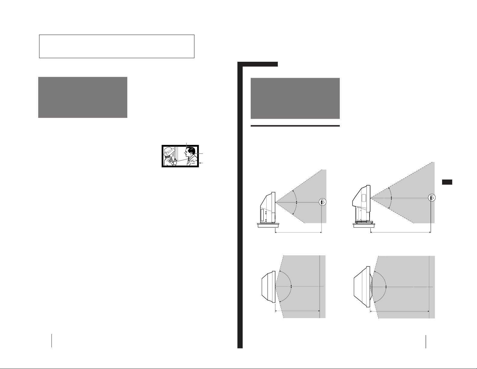
On blanking around the pciture
The monitor displays black masks between the picture
and the screen vessel because the monitor under-scans
to obtain the necessary space on the screen to display
the picture. This is called blanking. Note that the black
masks on each vessel are not uniform.
The blanking on the video picture will be wider to
optimize picture.
On moisture condensation
If the projection monitor is transported directly from a
cold to a warm location, or if the room temperature
has changed suddenly, the picture may be blurred or
show poor color. This is because moisture has
condensed on the lenses inside. If this happens, let the
moisture evaporate before using the monitor.
On cleaning
• Clean the cabinet of the monitor with a dry soft
cloth. Stubborn stains may be removed with a cloth
slightly dampened with solution of mild soap and
water, then wipe it with a dry soft cloth.
Do not use any type of solvent such as alcohol,
benzine, thinner or insecticide. Such solvent may
damage the finish of the monitor or erase the
indications on the panel.
• Wipe the screen with a dust remover (supplied)
occasionally, as the screen easily catches dust. The
dust remover is washable. Wash it with warm water
or mild detergent solution.
• Stubborn stains on the screen may be removed with
a soft cloth slightly dampened with solution of mild
soap and water.
• If the picture becomes dark after using the monitor
for a long period of time, it may be necessary to
clean the inside of the monitor. Consult qualified
service personnel.
Screen vessel
Picture
Blanking
Getting Started
5
-EN
EN
p for KL-W9000
Vertical viewing area (side view)
Horizontal viewing area (top view)
Getting Started
Step 1: Installing
the projection
monitor
Optimum viewing area
For the best picture quality, install the monitor within
the areas shown below.
p for KL-W7000
Vertical viewing area (side view)
Horizontal viewing area (top view)
30°
30°
2 m
75°
75°
2 m
35°
35°
75°
75°
1.5 m
1.5 m
from the Operating Instruction Manual. The page numbers of
the Operating Instruction Manual remain as in the manual.
– 5 –
SECTION 1
GENERAL
Page 6
6
-EN
Getting Started
2
Pass a strong cord or a chain through each
bracket mounted in step 1, and then secure
it to a wall or a pillar, etc.
Using the buckle
You can also use the supplied buckle to secure the
monitor to the stand.
1
Attach the buckle to the stand on which the
monitor is mounted.
Tighten the supplied screw firmly.
2
Insert the buckle until it clicks.
3
Pull the belt to fasten.
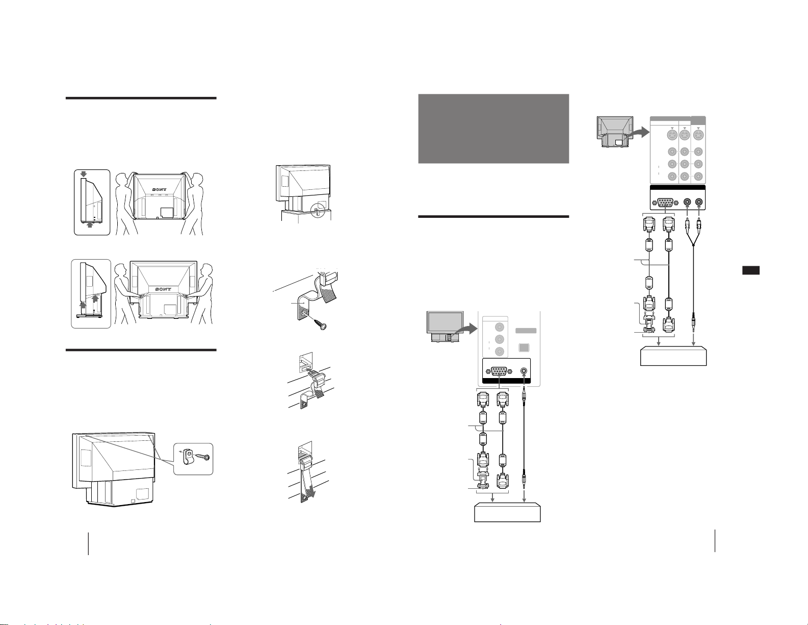
Carrying your monitor
Be sure to grasp the areas indicated by the arrows
when carrying the monitor, and to use more than two
people. Never grasp the front panel.
p for KL-W7000
p for KL-W9000
Stabilizing the monitor
Using the brackets
After setting up, secure the monitor to a wall, etc. with
the supplied brackets.
1
Mount the two supplied brackets with the
screws to the upper rear sides of the
monitor.
Bracket (supplied)
Belt
Getting Started
7
-EN
EN
Using the rear RGB 1 IN connector
* The HD15–HD15 adaptor (supplied) may be needed for some
models. The male side (without the No. 9 pin) of the adaptor
should be connected to the computer.
For customers using the supplied HD15–HD15
adaptor
This monitor uses a No. 9 pin in the video signal
connector for DDC1 and DDC2B compatibility.
Some PC systems which are not compatible with either
DDC1 or DDC2B may not accept the No. 9 pin. If you
are not sure whether your PC system accepts the No. 9
pin or not, use the HD15 (Female) – HD15 (Male
without the No. 9 pin) adapter (supplied).
Step 2: Hookup
Before making the connection, turn off the power and
disconnect the AC power cords of the monitor and the
equipment to be connected. Refer to the instruction
manual of the equipment you connect.
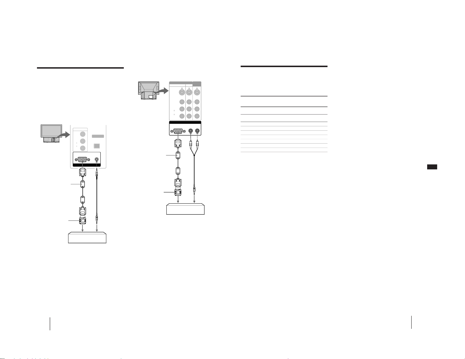
Connecting to an IBM PC/AT or
compatible computer
Connect the RGB 2 IN connector on the front or the
RGB 1 IN connector at the rear of the monitor to the
video/audio outputs of the computer using the
supplied RGB signal cable (D-sub 15 pin ˜ D-sub 15
pin).
Using the front RGB 2 IN connector
Rear of the monitor
RGB signal cable
(supplied)
HD15–HD15 adaptor
(supplied)*
to video output
Audio connecting
cord
(phono plug × 2 ˜
stereo minijack)
(not supplied)
to audio output
IBM PC/AT or compatible
computer
Front of the monitor
RGB signal cable
(supplied)
HD15–HD15 adaptor
(supplied)*
to video output
Audio connecting
cord
(stereo minijack ˜
stereo minijack)
(not supplied)
to audio output
IBM PC/AT or compatible
computer
Male side
(without the No.9 pin)
Male side (without
the No.9 pin)
or
or
INPUT SELECT
VIDEO
R
L
AUDIO
VIDEO 2 IN
RESET
RGB AUDIO
RGB 2 IN
RGB 1 IN
AUDIO
L
R
RGB
VIDEO IN
S VIDEO
VIDEO
R
L
AUDIO
VIDEO
OUT
13
– 6 –
Page 7
8
-EN
Getting Started
INPUT SELECT
VIDEO
R
L
AUDIO
VIDEO 2 IN
RESET
RGB AUDIO
RGB 2 IN
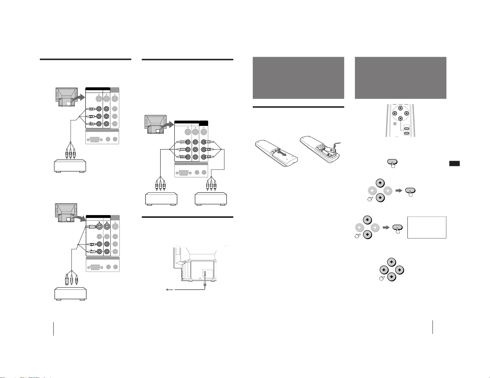
Connecting to a Macintosh or
compatible computer
Connect the RGB 2 IN connector on the front or the
RGB 1 IN connector at the rear of the monitor to the
video/audio outputs of the computer using the
supplied RGB signal cable (D-sub 15 pin ˜ D-sub 15
pin) and the supplied Macintosh adaptor.
Using the front RGB 2 IN connector
Using the rear RGB 1 IN connector
About the supplied Macintosh adaptor
The supplied Macintosh adaptor is compatible with
Macintosh LC, Performa, Quadra and Power
Macintosh series computers. Macintosh II series and
some version of PowerBook models may need an
another adaptor with micro switches (not supplied).
Front of the monitor
RGB signal cable
(supplied)
Macintosh adaptor
(supplied)
to video output
Audio connecting
cord
(stereo minijack ˜
stereo minijack)
(not supplied)
to audio output
Macintosh or compatible
computer
Rear of the monitor
RGB signal cable
(supplied)
Macintosh adaptor
(supplied)
to video output
to audio output
Macintosh or compatible
computer
Audio connecting
cord
(phono plug × 2 ˜
stereo minijack)
(not supplied)
RGB 1 IN
AUDIO
L
R
RGB
VIDEO IN
S VIDEO
VIDEO
R
L
AUDIO
VIDEO
OUT
13
Getting Started
9
-EN
EN
Preset and user modes
Preset modes
The monitor has nine factory preset modes for the most
popular industry standards as shown below.
No. Resolution Horizontal Vertical Graphics
(dots × frequency frequency mode
lines) (kHz) (Hz)
1 640 × 400 31.468 70.086 VGA mode
(Text)
2 640 × 480 31.468 59.94 VGA mode
(Graphics)
3 800 × 600 37.879 60.317 SVGA VESA
4 800 × 600 46.875 75.000 SVGA VESA
5 1024 × 768 48.363 60.004 VESA
6 864 × 480 31.469 59.94 Sony Wide-VGA*
7 1072 × 600 37.879 60.317 Sony Wide-SVGA*
8 1376 × 768 48.363 60.004 Sony Wide-XGA*
9 640 × 480 34.954 66.667 Macintosh 13" color
* For the timing chart of the signals, see page 28.
User modes
When using a video mode that is not one of the preset
modes, some fine tuning may be required to optimize
the display to your preference. Simply adjust the
monitor according to the adjustments instructions on
page 16. The adjustments will be stored automatically
and recalled whenever that mode is used.
A total of 15 user-defined modes can be stored in
memory. If a 16th mode is entered, it will replace the
first.
Recommended horizontal timing
conditions
Horizontal sync width should be more than 1.0 µsec.
Horizontal blanking width should be more than 3.6
µsec.
When “OUT OF SCAN RANGE” appears on the screen
The monitor receives a signal whose frequency range is not
within that specified for the monitor.
Notes
• When projecting a Wide-VGA, Wide-SVGA or Wide-XGA
signal, set the picture mode to FULL. In NORMAL mode, the
picture with aspect ratio 16:9 will be compressed to aspect ratio
4:3 and appear lengthened vertically. For details, see page 15.
• The monitor does not accept an interlace mode signal.
Plug & Play
This monitor complies with the DDC
TM
1 and DDC2B
which are the Display Data Channel (DDC) standards
of VESA.
When a DDC1 host system is connected, the monitor
synchronizes with the V. CLK in accordance with the
VESA standards and outputs the EDID (Extended
Display Identification Data) to the data line.
When a DDC2B host system is connected, the monitor
automatically switches to each communication.
For customers using Windows 95
Install the new model information from the “Windows
95 Monitor Information Disk” into your PC. (To install
the file, refer to the supplied “About the Windows 95
Monitor Information Disk/File.”)
This monitor complies with the “VESA DDC”
Plug&Play standard. If your PC/video card complies
with DDC, select “Plug and Play Monitor (VESA
DDC)” as “Monitor type” from “Control Panel” in
Windows 95. Some PC/video cards do not comply
with DDC. Even if your computer complies with DDC,
it may have some problems connecting with this
monitor. In this case, select this monitor’s model name
(KL-W7000 or KL-W9000) as “Monitor type” in
Windows 95.
– 7 –
Page 8
10
-EN
Getting Started
Connecting two VCRs for editing
The monitor outputs signals from the VIDEO IN jacks
through the VIDEO OUT jacks. With two VCRs
connected to the VIDEO IN and VIDEO OUT jacks, you
can edit the tape.
Note
For the RGB signal input from the RGB 1/2 IN
connectors, the monitor outputs only the audio signal.
Connecting the AC power cord
Connect the supplied power cord to the AC IN socket
of the monitor and to a wall AC outlet.
RGB 1 IN
AUDIO
L
R
RGB
VIDEO IN
S VIDEO
VIDEO
R
L
AUDIO
VIDEO
OUT
13
Connecting to video equipment
To a VCR not equipped with an S video
connector
You can also use the VIDEO 2 IN jacks on the front of
the monitor for the video/audio connections.
To an S video equipped VCR
Rear of the monitor
to VIDEO 1 IN or
VIDEO 3 IN
VMC-810S/820S
(not supplied)
VCR
to video/audio outputs
to VIDEO 1 IN or
VIDEO 3 IN
YC-810S
(not supplied)
VCR
to S video/audio outputs
Rear of the monitor
VMC-810S/
820S
(not supplied)
VCR for playback
VMC-810S/820S
(not supplied)
VCR for recording
Rear of the monitor
to an AC outlet
AC power cord
(supplied)
to AC IN
Note
When you connect the cable to both the VIDEO jack and the S
VIDEO connector, the picture from the S VIDEO connector is
displayed on the monitor screen.
Rear of the monitor
to video/audio
outputs
to video/
audio
inputs
RGB 1 IN
AUDIO
L
R
RGB
VIDEO IN
S VIDEO
VIDEO
R
L
AUDIO
VIDEO
OUT
13
RGB 1 IN
AUDIO
L
R
RGB
VIDEO IN
S VIDEO
VIDEO
R
L
AUDIO
VIDEO
OUT
13
to VIDEO OUT
to VIDEO 1 IN
or VIDEO 3 IN
Getting Started
11
-EN
EN
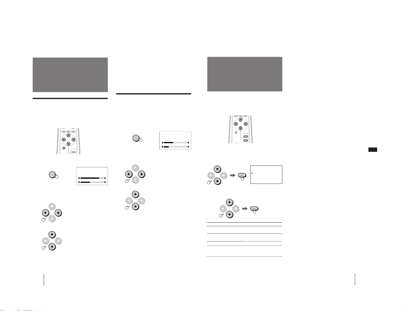
OPTION N
AUTO SHUT OFF:OFF
LANGUAGE: ENGLISH
Step 3: Setting up
the remote
control
Inserting batteries
Insert two size AA (R6) batteries (supplied) by
matching the + and – on the battery to the diagram
inside the battery compartment.
Notes
• Under normal conditions, batteries will last up to six months.
If the remote control does not operate properly, the batteries
may be worn out. When replacing batteries, replace both of
them with new ones.
• Do not mix old batteries with new ones or mix different types
of batteries together.
• If the electrolyte inside the battery should leak, wipe the
contaminated area of the battery compartment with a cloth and
replace the old batteries with new ones. To prevent the
electrolyte from leaking, remove the batteries when you don‘t
plan to use the remote control for a long period of time.
• Do not handle the remote control roughly. Do not drop it, step
on it, or let it get wet.
• Do not place the remote control in direct sunlight, near a
heater, or where the humidity is high.
If you prefer Spanish or French to English, you can
change the menu language.
1
Press MENU.
2
Press V or v to select OPTION, and press
ENTER.
3
Press V or v to select LANGUAGE, and press
ENTER.
4
Press B, V, v or b to select your favorite
language, “ENGLISH,” “FRANCAIS (French)”
or “ESPANOL (Spanish).”
5
Press MENU to return to the original
screen.
Notes
• You can operate the menu using the buttons on the monitor.
The VOLUME + button functions the same as V and b, and
VOLUME – as v and B.
• You cannot use the AUTO SHUT OFF function for the input
from VIDEO IN. (See page 22.)
Changing the menu
language
MENU
ENTER
ENTER
CENTER/
SIZE
VOL
ENTER
MENU
– 8 –
Page 9
12
-EN
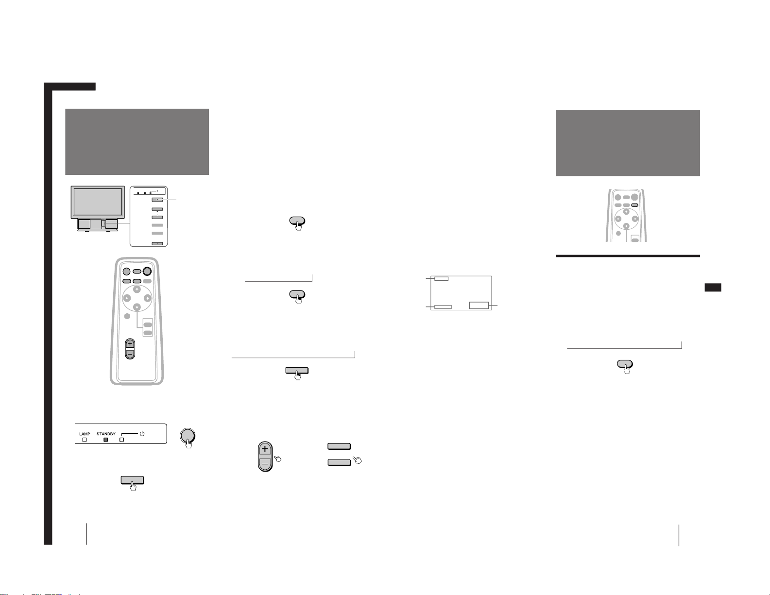
Operations
1
If the STANDBY indicator on the front of the
monitor is lit in orange, press POWER on the
remote control to turn on the power.
Press the power switch (green) on the monitor if the
STANDBY indicator is not lit.
The green u (power) indicator flashes, then lights
up.
2
Turn on the power of the connected
equipment.
3
Press RGB or VIDEO to select the input you
want to watch.
The selected input indication is displayed on the
screen.
To watch a computer picture input from the
RGB IN connector
Each time you press RGB, the display changes as
follows:
RGB 1 ˜ RGB 2
To watch a video picture input from the
VIDEO IN jacks
Each time your press VIDEO, the display changes
as follows:
VIDEO 1 n VIDEO 2 n VIDEO 3
You can also select the input by pressing INPUT
SELECT on the monitor.
Each time you press INPUT SELECT, the display
changes as follows:
RGB 1 n RGB 2 n VIDEO 1 n VIDEO 2 n VIDEO 3
The input signal indication will automatically
disappear.
4
Press VOL +/– (VOLUME +/–) to adjust the
volume.
Remote control Monitor
Projecting the
picture
Operations
CENTER/
SIZE
VOL
ENTER
MENU
VIDEO
MUTING
DISPLAY
POWER
RGB WIDE
POWER
RGB
INPUT SELECT
VIDEO
N
N
VOL
VOLUME
+
–
MENU
VOLUME
LAMP
INPUT SELECT
STANDBY
ENTER
Power switch
(green)
13
-EN
Operations
EN
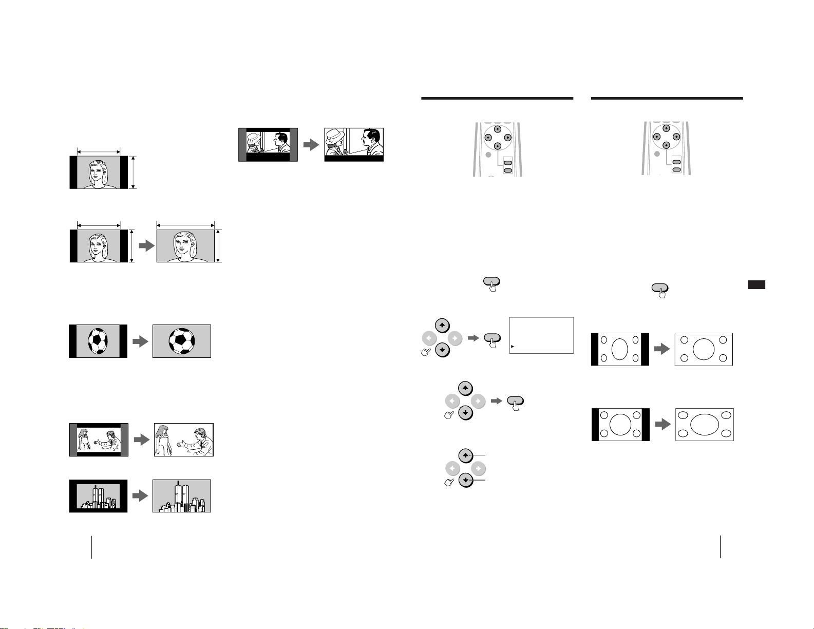
Watching the video picture in wide
mode
You can enjoy a variety of wide mode picture.
Press WIDE until the mode you want appears
on the screen.
Each time you press WIDE, the mode changes as
follows:
NORMAL n FULL n ZOOM n SUB TITLE n WIDE ZOOM
To turn off the monitor
Press POWER on the remote control. The monitor
enters standby mode and the STANDBY indicator
lights up. To turn off the main power, press the power
switch (green) on the monitor.
Note
To protect the lamp mounted as a source of light, if you try to
turn on the power within about 30 minutes after the power has
been turned off, the u (power) indicator flashes and the picture
does not appear.
Muting the sound
Press MUTING.
“MUTING” appears on the screen.
To restore the sound, press MUTING again, or press
VOL+.
Displaying on-screen information
Press DISPLAY to display the following information on
the screen.
To make the on-screen information disappear, press
DISPLAY again.
Current input
signal
Picture mode
(page 14)
Current input
signal frequency
when the RGB
signal* is input
Watching the
picture in wide
picture mode
N
WIDE
CENTER/
SIZE
MENU
VIDEO
MUTING
DISPLAY
POWER
RGB WIDE
(continued)
*fH: Horizontal frequency
fV: Vertical frequency
“OUT OF SCAN RANGE” appears if the scanning
frequency range is not within the acceptable
limits. (See page 9.)
NORMAL
RGB 1
fv:75
fh:37.5
– 9 –
Page 10
14
-EN
Operations
The wide-format picture is enlarged and the subtitle area is
compressed so that the picture is aligned with the screen size.
The picture is enlarged horizontally and vertically and the upper
and lower portions of the picture are compressed to the screen size.
Recommended picture mode
When watching a picture with normal aspect
ratio 4:3
Select NORMAL.
Select WIDE ZOOM.
When watching a picture recorded after a 16:9
picture has been compressed to aspect ratio
4:3
Select FULL.
When watching a wide-format movie or
software with black bands and subtitles (with
subtitles inside the picture)
Select ZOOM.
The wide-format picture is enlarged horizontally and vertically to
the screen size.
The picture with normal
ratio 4:3 is displayed as it is.
When watching a movie or software with
subtitles (with subtitles outside the picture)
Select SUB TITLE.
Note
• You can also change the picture mode by using the menu.
Notes on wide picture modes
• Select a picture mode taking into account that one which
changes the aspect ratio of the original picture will provide an
appear different from that of the original image.
• If the monitor is used for profit or for public viewing,
modifying the original picture by changing picture modes may
constitute an infringement of the rights of authors or producers
which are legally protected by laws.
• When a normal 4:3 picture is watched in WIDE ZOOM mode,
the surrounding portions may be cut off or modified. The
original picture can be viewed in NORMAL mode.
Hello,Anne.
Hello,Anne.
Good-bye,Jane.
Good-bye.
Good-bye,Jane.
Good-bye.
4
3
4
3
16
9
The picture compressed to aspect ratio 4:3 is enlarged horizontally
to the screen size.
The picture with aspect ratio 16:9 is enlarged to the screen size as it
is.
15
-EN
Operations
EN
ASPECT N
ASPECT: ZOOM
V SCROLL: 0
Adjusting the vertical position of the
video picture
You can scroll the picture up or down when:
• the upper or lower portions of the picture in WIDE
ZOOM mode are cut off.
• you want to move the picture in ZOOM mode as
you like.
• subtitles are lost from the screen in SUB TITLE
mode.
Scrolling the picture functions on the WIDE
ZOOM, ZOOM and SUB TITLE modes only.
1
Press MENU.
2
Press V or v to select ASPECT, and press
ENTER.
3
Press V or v to select V SCROLL, and press
ENTER.
4
Press V or v to adjust the vertical position
of the picture.
Note
• You can operate the menu using the buttons on the monitor.
The VOLUME + button functions the same as V and b, and
VOLUME – as v and B.
The picture with aspect ratio 16:9 is enlarged to the screen size.
Watching the computer picture in wide
picture mode
If you set the picture mode to FULL when a WideVGA, Wide-SVGA or Wide-XGA signal is received,
you can watch the picture with aspect ratio 16:9 as it is.
The Wide-VGA, Wide-SVGA and Wide-XGA signals
are independently standardized by Sony. When you
use the signals with the timing chart on page 28, you
can obtain an effective wide mode picture.
Press WIDE to display FULL or NORMAL on the
screen.
Each time your press WIDE, you can select FULL and
NORMAL alternately.
When a Wide-VGA, Wide-SVGA or Wide-XGA
signal is received
NORMAL mode FULL mode
When a conventional VGA, SVGA or XGA signal
is received
NORMAL mode FULL mode
Adjusting the position of a computer
picture
You can move the picture up, down, right or left to
make it easy to watch by using the SIZE/CENTER
button. For details, see page 16.
If you watch the Wide-VGA, Wide-SVGA or WideXGA signal in NORMAL mode
A 16:9 picture will be compressed horizontally to a 4:3 picture.
MENU
ENTER
ENTER
to move the picture up
to move the picture down
WIDE
The picture with aspect ratio 4:3 is enlarged horizontally to the
screen size.
CENTER/
SIZE
VOL
ENTER
MENU
CENTER/
SIZE
VOL
ENTER
MENU
– 10 –
Page 11
16
-EN
Operations
Adjusting the position (CENTER)
After projecting the picture from a computer, you may
need to adjust the position of the picture to fit the
monitor screen. You can also move the picture as you
like. The setting is only for the input signal displayed
on the screen.
1
Press CENTER/SIZE until the CENTER
adjustment screen appears.
2
Press B, b, V or v to adjust the position.
For horizontal adjustment press B or b. (H
CENTER)
For vertical adjustment press V or v. (V CENTER)
The CENTER adjustment screen automatically
disappears after about 10 seconds if you do not press
any button. You can also erase the CENTER adjustment
screen by pressing CENTER/SIZE again.
CENTER/
SIZE
MENU
VIDEO RGB WIDE
Adjusting the
computer picture
CENTER/
SIZE
To reset to the factory preset setting
Press RESET on the monitor. At the same time, the
picture size and video/audio settings (pages 17 to 21)
are also reset to the factory preset levels.
Note
• You can adjust the position by using the CENTER/SIZE and
ı/◊/√/∫ buttons on the monitor.
Adjusting the picture size (SIZE)
After projecting the picture from a computer, you may
need to adjust the picture size to fit the monitor screen.
The setting is only for the input signal displayed on the
screen.
1
Press CENTER/SIZE until the SIZE adjustment
screen appears.
2
Press B, b, V or v to adjust the picture size.
For horizontal adjustment press B or b. (H SIZE)
For vertical adjustment press V or v. (V SIZE)
The SIZE adjustment screen automatically disappears
after about 10 seconds if you do not press any button.
You can also erase the SIZE adjustment screen by
pressing CENTER/SIZE again.
To reset to the factory preset setting
Press RESET on the monitor. At the same time, the
picture position and video/audio settings (pages 17 to
21) are also reset to the factory preset levels.
Notes
• For a picture with resolution of 640 × 350, 640 × 400 or 640 ×
480, the vertical size cannot be increased from the size that was
projected the first time.
• You can adjust the size using the CENTER/SIZE and ı/◊/√/
∫ buttons on the monitor.
CENTER/
SIZE
V: to move the picture up
v: to move the picture down
b: to increase horizontal size
B: to decrease horizontal size
V: to increase vertical size
v: to decrease vertical size
b: to move the picture right
B: to move the picture left
CENTER
H CENTER
V CENTER
SIZE
H SIZE
V SIZE
17
-EN
Operations
EN
VIDEO/AUDIO N
PRESENTATION
STANDARD
MOVIE
AV MEMORY
VIDEO ADJUST
AUDIO ADJUST
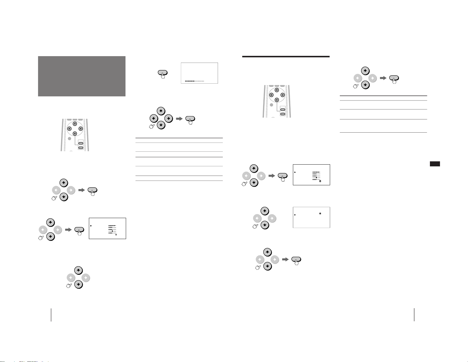
The video/audio mode feature allows you to choose
four different modes of picture/sound settings. Choose
the one that best suits the type of program that you
want to watch.
1
Press MENU.
2
Press V or v to select VIDEO/AUDIO, and
press ENTER.
3
Press V or v to select the desired item, and
press ENTER.
Selecting the preset
picture viewing
mode
ENTER
ENTER
To reset to the factory preset setting
Press RESET on the monitor.
When watching a computer picture, the mode resets to
PRESENTATION. When watching a video picture, the
mode resets to STANDARD. At the same time, the
position and size of a computer picture (page 16) are
also reset to the factory preset levels. The settings in
AV MEMORY do not reset.
Note
• You cannot adjust the settings in modes other than AV
MEMORY.
Choose To
PRESENTATION Watch the picture input from a
computer.
STANDARD Watch the picture input from video
equipment.
MOVIE Watch a movie.
AV MEMORY Adjust the quality of the picture/sound
to suit your taste. (For details, see pages
18–21.)
4
Press MENU to return to the original screen.
CENTER/
SIZE
VOL
ENTER
MENU
– 11 –
Page 12
18
-EN
Operations
MENU
N
CONTRAST
BRIGHTNESS
COLOR
HUE
SHARPNESS
RESET
VIDEO ADJUST
BRIGHTNESS
VIDEO ADJUST
(2) Press ENTER.
5
Adjust the selected item.
Press V, b, v or B to adjust the item, and press
ENTER.
6
To adjust other items, repeat steps 4 and 5.
7
Press MENU to return to the original screen.
To reset to the factory preset setting
Move the cursor (”) to RESET at the bottom of the
VIDEO ADJUST menu, and press ENTER.
Notes
• When the RGB signal is input, COLOR, HUE and SHARPNESS
cannot be adjusted.
• You can adjust the items in AV MEMORY for each input from
VIDEO 1, 2 and 3, and RGB 1 IN and RGB 2 IN.
• You can operate the menu using the buttons on the monitor.
VOLUME + functions the same as V and b, and VOLUME – as
v and B.
ENTER
Adjusting the
picture
(AV MEMORY)
You can adjust the quality of the picture to suit you
taste and store the settings into AV MEMORY.
1
Press MENU.
2
Press V or v to select VIDEO/AUDIO, and
press ENTER.
3
Press V or v to select VIDEO ADJUST, and
press ENTER.
4
Select the item you want to adjust.
For example:
(1) To adjust the brightness, press V or v to move
the cursor (”) to BRIGHTNESS.
ENTER
ENTER
CENTER/
SIZE
VOL
ENTER
MENU
Item
CONTRAST
BRIGHTNESS
COLOR
HUE
SHARPNESS
Press v or B to
Decrease picture
contrast.
Darken the picture.
Decrease color
intensity.
Make picture tones
become purplish.
Soften the picture.
Press V or b to
Brighten the picture.
Brighten the picture.
Increase color intensity.
Make picture tones
become greenish.
Sharpen the picture.
ENTER
19
-EN
Operations
EN
MENU
N
CONTRAST
BRIGHTNESS
COLOR
HUE
SHARPNESS
RESET
VIDEO ADJUST
MENU
N
NR: OFF
H-WHITE: ON
COLOR TEMP:
MEDIUM
RESET
VIDEO ADJUST
Adjusting the picture in more details
You can adjust the picture with the NR (noise
reduction), H-WHITE and COLOR TEMP
(temperature) options.
1
Press MENU.
2
Press V or v to select VIDEO/AUDIO, and
press ENTER.
3
Press V or v to select VIDEO ADJUST, and
press ENTER.
4
Press V or v to move the cursor (”) to
RESET, then press v again.
5
Select the desired item with V or v, then
press ENTER.
6
Press V or v to adjust the item, then press
ENTER.
7
To adjust other items, repeat steps 5 and 6.
8
Press MENU to return to the original screen.
To reset to the factory preset setting
Move the cursor (”) to RESET at the bottom of the
VIDEO ADJUST menu, and press ENTER.
Notes
• You can adjust the items in AV MEMORY for each input from
VIDEO 1, 2 and 3, and RGB 1 IN and RGB 2 IN.
• You can operate the menu using the buttons on the monitor.
VOLUME + functions the same as V and b, and VOLUME – as
v and B.
ENTER
Choose
NR (Noise Reduction)
H-WHITE
COLOR TEMP (Color
temperature)
To
Reduce picture noise. You can choose
LOW or HIGH position.
Emphasize the white color with the
ON position.
Make the white color warm (reddish)
with the LOW position. Make it cool
(bluish) with the HIGH position.
CENTER/
SIZE
VOL
ENTER
MENU
ENTER
ENTER
– 12 –
Page 13
20
-EN
Operations
You can adjust the quality of the sound to suit you taste
and store the settings into AV MEMORY.
1
Press MENU.
2
Press V or v to select VIDEO/AUDIO, and
press ENTER.
3
Press V or v to select AUDIO ADJUST, and
press ENTER.
4
Select the item you want to adjust.
For example:
(1) To adjust the bass, press V or v to move the
cursor (”) to BASS.
(2) Press ENTER.
MENU
N
TREBLE
BASS
BALANCE
EFFECT:
OFF
RESET
AUDIO ADJUST
5
Adjust the selected item.
Press V, b, v or B to adjust the item, and press
ENTER.
6
To adjust other items, repeat steps 4 and 5.
7
Press MENU to return to the original screen.
To reset to the factory preset setting
Move the cursor (”) to RESET at the bottom of the
AUDIO ADJUST menu, and press ENTER.
Notes
• You can adjust the items in AV MEMORY for each input from
VIDEO 1, 2 and 3, and RGB 1 IN and RGB 2 IN.
• You can operate the menu using the buttons on the monitor.
VOLUME + functions the same as V and b, and VOLUME – as
v and B.
Adjusting the sound
(AV MEMORY)
ENTER
ENTER
ENTER
Item
TREBLE
BASS
BALANCE
Press V or b to
Increase the treble
response.
Increase the bass
response.
Emphasize the right
speaker’s volume.
Press v or B to
Decrease the treble
response.
Decrease the bass
response.
Emphasize the left
speaker’s volume.
BASS
AUDIO ADJUST
CENTER/
SIZE
VOL
ENTER
MENU
ENTER
21
-EN
Operations
EN
MENU
N
TREBLE
BASS
BALANCE
EFFECT:
OFF
RESET
AUDIO ADJUST
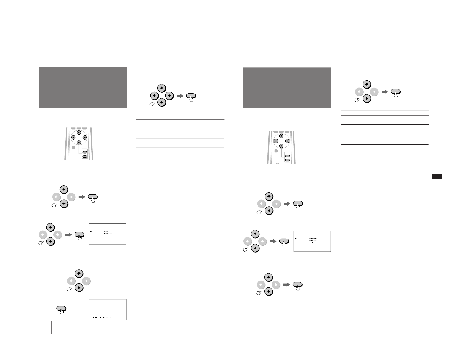
Audio effect mode allows you to enjoy dynamic sound
with surround-like effect.
1
Press MENU.
2
Press V or v to select VIDEO/AUDIO, and
press ENTER.
3
Press V or v to select AUDIO ADJUST, and
press ENTER.
4
Press V or v to select EFFECT, and press
ENTER.
5
Press V or v to select the desired item, and
press ENTER.
6
Press MENU to return to the original screen.
To reset to the factory preset setting
Move the cursor (”) to RESET at the bottom of the
AUDIO ADJUST menu, and press ENTER.
Notes
• You can adjust the items in AV MEMORY for each input from
VIDEO 1, 2 and 3, and RGB 1 IN and RGB 2 IN.
• You can operate the menu using the buttons on the monitor.
VOLUME + functions the same as V and b, and VOLUME – as
v and B.
ENTER
Selecting the audio
effect
(EFFECT)
CENTER/
SIZE
VOL
ENTER
MENU
ENTER
Choose
HALL SURROUND 1
HALL SURROUND 2
SIMULATED STEREO
OFF
To
Receive dynamic threedimensional sound.
Watch a movie.
Receive monaural sound with
surround-like effect.
Cancel audio effect.
ENTER
ENTER
– 13 –
Page 14
22
-EN
Operations
OPTION N
AUTO SHUT OFF:OFF
LANGUAGE: ENGLISH
You can set the monitor to turn off when the time you
specify has passed after the input of the sync signal
from the computer shut off.
1
Press MENU.
2
Press V or v to select OPTION, and press
ENTER.
3
Press V or v to select AUTO SHUT OFF, and
press ENTER.
4
Press B or b to select 60 (minutes), 90
(minutes) or 120 (minutes), and press
ENTER.
5
Press MENU to return to the original screen.
After the time you specify in step 4 has passed after
cancellation of the input of the sync signal, the power
turns off and the STANDBY indicator and the u
indicator will light up.
The power turns on if you press POWER on the remote
control or a signal is input from the computer again.
Note
• You cannot use this function for the input from VIDEO IN.
Turning the power
off automatically
(AUTO SHUT OFF)
MENU
ENTER
ENTER
ENTER
CENTER/
SIZE
VOL
ENTER
MENU
23
-EN
Additional Information
EN
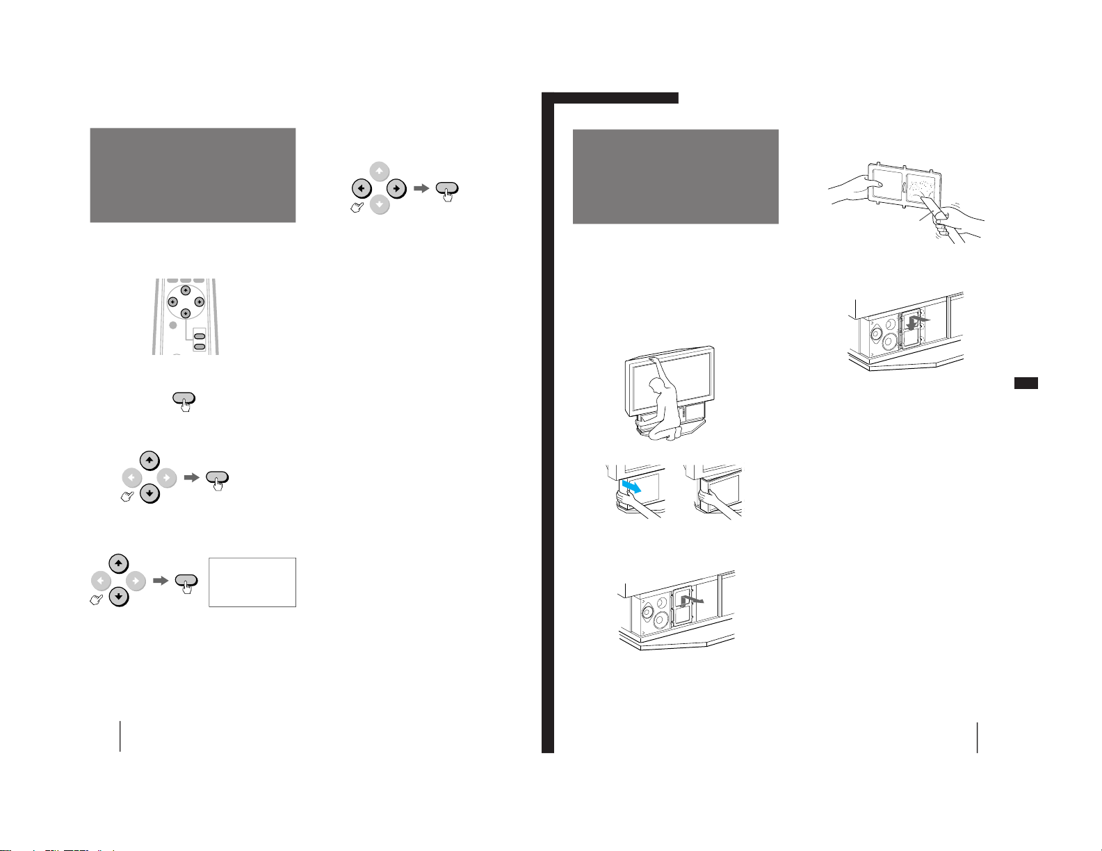
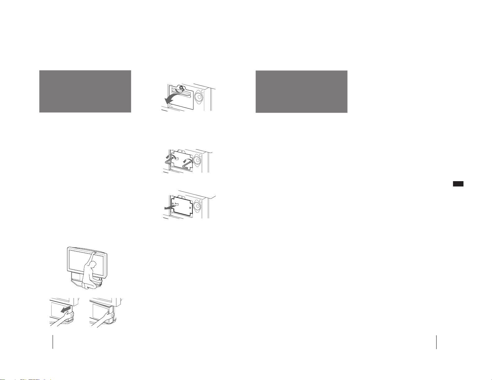
The air filter should be cleaned once a month. When it
becomes difficult to remove the dust, replace the filter
with a new one. To clean the filter, follow the steps
below.
1
Turn off the power switch on the monitor
and unplug the power cord.
2
Remove the front panel from the monitor.
Pull the panel towards you, holding its left
end. Be careful not to damage your nails.
3
Pull the air filter upwards to remove.
Cleaning the air
filter
4
Remove the dust from the filter with a
vacuum cleaner.
5
Attach a new filter to the monitor.
Fit the six projections securely.
6
Mount the front panel.
Be careful not to injure the speakers.
Notes
• Clean the air filter periodically. Otherwise, the temperature
inside the monitor may rise abnormally.
• Do not use a torn filter. Fit the six projections on the filter to the
monitor securely. Dust inside the monitor may cause distorted
picture and also fire.
• Be sure to attach the air filter securely. Otherwise, the monitor
will not turn on.
• Contact your Sony dealer for a new filter.
Hold the monitor tightly.
Additional Information
Vacuum cleaner
– 14 –
Page 15
24
-EN
Additional Information
Replacing a lamp
If the screen becomes dark, the color looks unusual, or
the LAMP indicator on the front of the monitor flashes,
it is time to replace the lamp with a new one.
Before replacement
• Be sure to use the Sony XL-100U lamp unit (not supplied) for
replacement. Use of other lamps causes damage to the
monitor.
• Do not remove the lamp for any purpose other than
replacement.
• Before replacement, be sure to turn off the monitor and unplug
the power cord.
• When replacing the lamp, let it cool down completely, as the
surface of the lamp remains hot for at least 30 minutes after the
power has been switched off.
• Do not leave the removed lamp near the inflammable
materials.
• Do not pour water onto the removed lamp, nor put any object
inside the lamp.
• Do not put inflammable materials and metal objects inside the
lamp receptacle on the monitor, after removing the lamp. Do
not touch the receptacle.
• Fit the new lamp securely, otherwise the screen may become
dark, or it may cause fire.
1
Turn off the power switch on the monitor
and unplug the power cord.
Wait at least 30 minutes to allow the lamp to cool
down before replacing it .
2
Remove the front panel.
3
Untighten the screw with a coin or similar
object to remove the lamp cover.
4
Loosen the two screws that secure the
lamp, then pull out the lamp.
The lamp is very hot immediately after use. Never
touch the front glass of the lamp or the
surrounding parts.
Loosen the two screws with the hexagon
head wrench (supplied with the lamp).
Pull out straight towards you by holding the
handle.
Replace the removed lamp into the empty box of
the replacement lamp.
5
Mount the new lamp and tighten the two
screws securely.
6
Mount the lamp cover and tighten the
screw.
7
Mount the front panel.
Be careful not to damage the speakers of the
monitor.
Notes
• Do not touch the front glass of a new lamp or the glass of the
lamp receptacle. This may reduce picture quality or lamp life.
• Be sure to attach the lamp securely. Otherwise, the monitor
will not turn on.
• A laud sound may be heard when the lamp burns. This is not
dangerous.
• Consult your Sony dealer for the XL-100U lamp unit.
Pull the panel towards you, holding its right
end. Be careful not to damage your nails.
Hold the monitor tightly.
25
-EN
Additional Information
EN
Troubleshooting
If the problem persists after trying the methods below,
contact your nearest Sony dealer.
No picture
/
Check that the power cord is connected
firmly.
/
Is the power of the monitor turned on?
/
Is the air filter mounted securely? (page 23)
/
Is the lamp cover attached securely? (page
24)
/
Check that the power of the connected
equipment is turned on.
/
Try to press any key on the connected
computer.
/
Check that the RGB signal cable or audio/
video cords are properly connected. (The
supplied HD15-HD15 adaptor may be
needed for some models of IBM PC/AT or
compatible computers. For a Macintosh or
compatible computer use the supplied
Macintosh adaptor.)
/
Make sure that no pins on the HD15
connectors are bent.
/
Check that the video card is seated
completely in the proper bus slot.
/
Check that the frequency range of the input
signal is within that specified for the
monitor. (If not, “OUT OF SCAN RANGE”
appears on the screen.)
/
The monitor does not accept an interlace
mode signal.
/
For customers using Windows 95 — If “KLW7000” or “KL-W9000” is not displayed as
“Monitor type” when selecting “SONY” as
“Manufacturer” from the device select
screen in Windows 95, select “Standard
monitor” as “Manufacturer” and “Plug and
Play monitor (VESA DDC)” as “Monitor
type,” or select “SONY Corporation” as
“Manufacturer” and “KL-W7000” or “KLW9000” as “Monitor type.”
Picture and sound output are delayed
/
When the green u (power) indicator on the
front is flashing, the monitor is warming
up.
/
It will take 30 minutes for the monitor to
display the picture again after the monitor
is switched off.
Screen lit and cannot see the picture
/
Be sure that you are watching the monitor
within the optimum viewing area. (page 5)
Good picture, no sound
/
Press VOL+ (VOLUME+).
/
Press MUTING so that “MUTING”
disappears from the screen. (page 13)
Fuzzy picture
/
Set the NR option in the VIDEO ADJUST
menu to LOW or HIGH.
/
If you use the monitor in a cold place,
moisture condensation may have occurred.
Leave the monitor as it is to let moisture
evaporate.
Dark picture
/
Replace the lamp for the light source with a
new one. (page 24)
No color, abnormal color
/
Adjust the picture in the VIDEO ADJUST
menu. (page 18)
Double images
/
Use of an extension cable, excessive cable
length or loose connection can produce this
symptom.
Computer picture not centered or sized
properly
/
Adjust the centering and size so that the
picture fits the screen. (page 16)
Distorted picture
/
Check your video card manual for proper
monitor setting.
/
Check that the frequency and the graphic
mode at which you are trying to input is
within the acceptable range. (page 9)
Even within the proper range some video
cards may have a sync pulse that is too
narrow for the monitor to sync correctly.
No picture, no sound from the connected
equipment
/
Are all the connecting cables connected?
/
Try to press the RGB or VIDEO button on
the remote control. (page 12)
The remote control does not function.
/
Are the batteries worn out?
The humming noise of fans is heard even after
the monitor has been turned off.
/
The fans installed inside the monitor are
working to prevent internal heat build-up.
They will stop about 2 minutes later.
– 15 –
Page 16
26
-EN
Additional Information
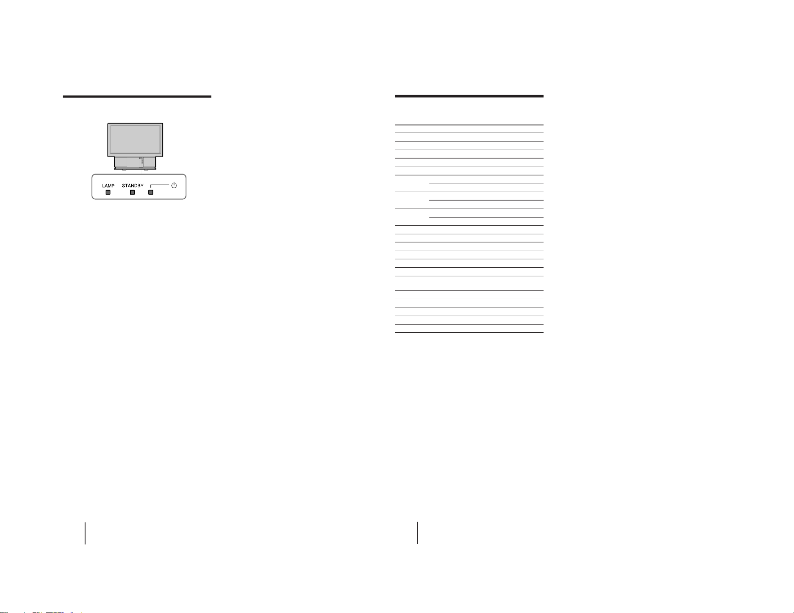
What flashing of the indicators on the
front of the monitor means
The u (power) (green), STANDBY (orange) and/or
LAMP (red) indicators indicate the conditions of the
monitor and warnings by lighting or flashing, as
follows.
The u indicator lights.
/
The power of the monitor is on.
The STANDBY indicator lights.
/
The monitor is in standby mode. The
monitor is turned on by pressing POWER
on the remote control.
The u and STANDBY indicators light.
/
The Auto Shut Off function works. The
monitor has been turned off when the time
you specify has passed after the input of
the computer is cut off.
The u indicator flashes.
/
The lamp for the light source is ready to
turn on. Within 30 minutes the picture is
displayed on the screen.
The LAMP and STANDBY indicators flash.
/
The air filter or the lamp cover is not
attached securely. When you correct, the
STANDBY lamp lights up and the monitor
enters the standby mode. (pages 23, 24)
The LAMP indicator flashes.
/
The lamp for the light source burns out.
Replace it with new one. (page 24)
The LAMP, STANDBY and u indicators flash.
/
The temperature inside the monitor has
risen abnormally, or the fans have stopped.
Check that the air filter is not clogged and
the ventilation holes are not blocked. After
a while turn on the monitor. (page 23)
If the monitor is not recovered after correcting the
problems, contact with qualified Sony personnel.
28
-EN
Additional Information
Wide-VGA Wide-SVGA Wide-XGA
Pixel Clock (MHz) 34.238 53.94 87.44
1dot (nsec) 29.207 18.539 11.436
1H (µsec) 31.777 26.4 20.676
H-Active (µsec) 25.235 19.874 15.736
H-Blank (µsec) 6.542 6.526 4.94
H-Front porch (µsec) 0.701 0.89 0.366
(dots) 24 48 32
H-Sync (µsec) 3.738 3.263 2.104
(dots) 128 176 184
H-Back porch (µsec) 2.103 2.373 2.47
(dots) 72 128 216
H-Sync Polarity – – –
V-TTI Time (Lines) 525 628 806
V-Addr Time (Lines) 480 600 768
V-Blank Start (Lines) 488 600 768
V-Blank Time (Lines) 29 28 38
V-Sync Start (Lines) 490 601 771
V Bottom Border 8 0 0
(Lines)
V Front Porch (Lines) 2 1 3
Ver Sync Time (Lines) 2 4 6
V Back Porch (Lines) 25 23 29
V Top Border (Lines) 8 0 0
V-Sync Polarity + + +
Timing chart for the Wide-VGA, WideSVGA and Wide-XGA signals
– 16 –
Page 17
29
-EN
Additional Information
EN
MENU
VOLUME
LAMP
INPUT SELECT
STANDBY
RGB 2 IN
VIDEO
R
L
AUDIO
VIDEO 2 IN
RESET
ENTER
CENTER/SIZE
RGB AUDIO
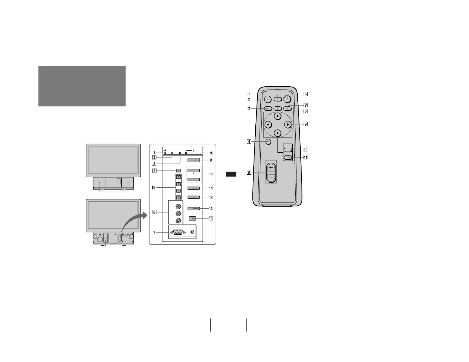
1 Remote sensor
2 LAMP indicator (pages 24, 26)
3 STANDBY indicator (pages 12, 26)
4 CENTER/SIZE button (page 16)
5 ◊/√/ı/∫ buttons (page 16)
6 VIDEO 2 IN jacks (page 10)
7 RGB 2 IN connector (pages 7, 8)
Identifying the
parts
With the front panel
attached
With the front
panel removed
Front panel
Air filter part
(page 23)
Lamp part
(page 24)
8 u (power) indicator (pages 12, 26)
9 Power switch (page 12)
!º VOLUME +/– buttons (page 12)
!¡ MENU button (page 11)
!™ ENTER button (page 11)
!£ INPUT SELECT button (page 12)
!¢ RESET button (pages 16, 17)
This section briefly describes the buttons and controls
on the monitor and on the remote control. For more
information, refer to the pages next to each description.
Projection monitor — Front
30
-EN
Additional Information
RESET
CENTER/
SIZE
VOL
ENTER
MENU
VIDEO
MUTING
DISPLAY
POWER
RGB WIDE
1 DISPLAY button (page 13)
2 MUTING button (page 13)
3 VIDEO button (page 12)
4 CENTER/SIZE button (page 16)
5 VOL (volume) +/– buttons (page 12)
6 POWER button (page 12)
7 WIDE button (pages 13, 15)
8 RGB button (page 12)
9 V/v/B/b buttons (pages 11, 16)
!º MENU button (page 11)
!¡ ENTER button (page 11)
Remote control
– 17 –
Page 18
SECTION 2
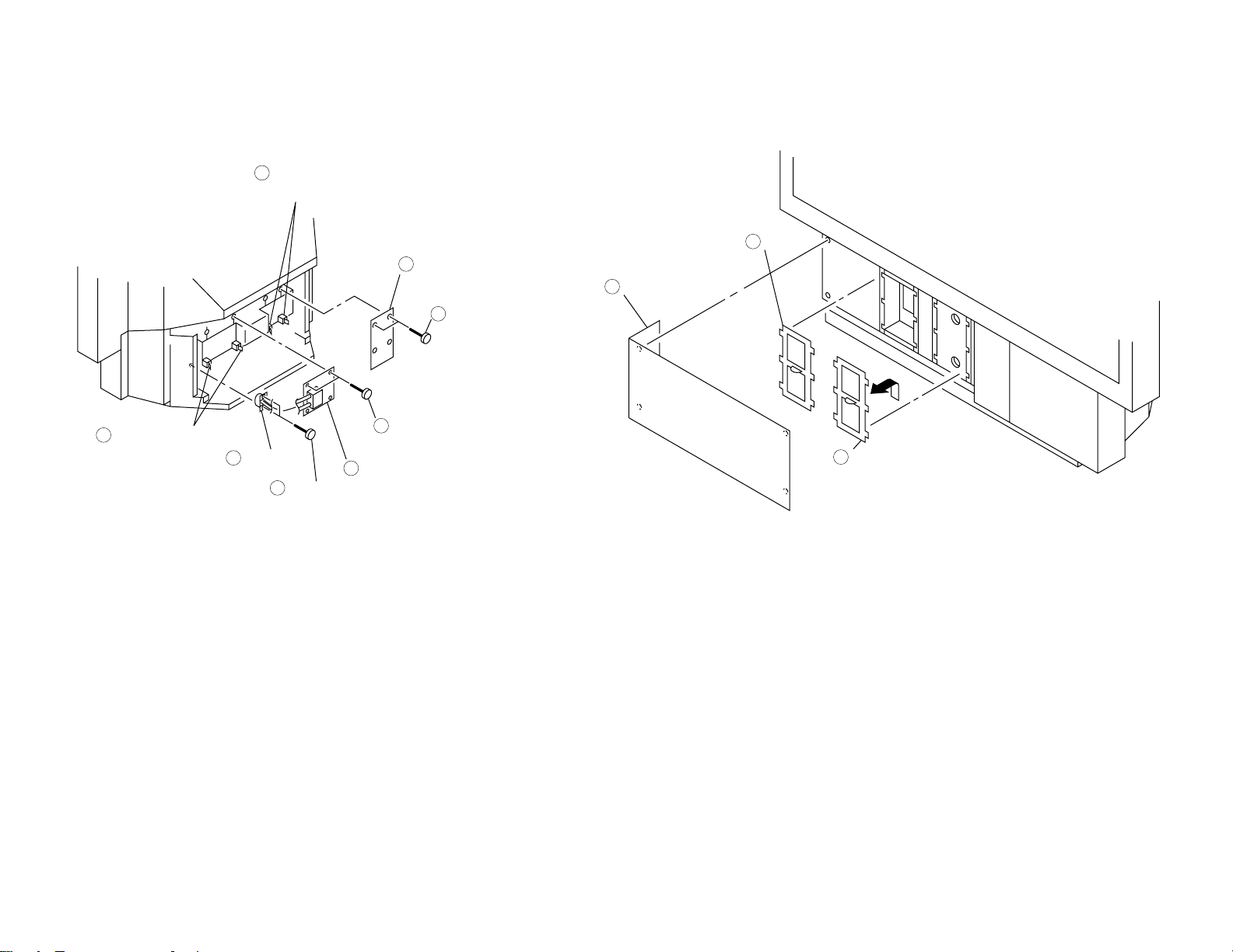
Rear cover
2
Twelve screws
(+BVTP 4 x 16)
1
Chassis assy
Chassis assy
2
Two screws
(+BVTP 4 x 16)
1
Five screws
(+BVTP 3 x 12)
1
U bracket
3
Two claws
4
U board
5
Two claws
2
DISASSEMBLY
2-1. REAR COVER REMOVAL 2-3. SERVICE POSITION
– 18 –
2-4. U BOARD REMOVAL2-2. CHASSIS ASSY REMOVAL
Page 19
2-5. POWER BLOCK AND K BOARD REMOVAL 2-6. FILTER REMOVAL
Power block
5
Terminal
2
Two printed circuit
board holders
4
K board
8
Two printed circuit
board holders
7
Two screws
(+BVTP 4 x 16)
6
Two screws
(+BVTP 4 x 16)
3
Two screws
(+BVTP 3 x 12)
1
Filter
2
Front panel (L)
1
Filter
(Reserve)
3
– 19 –
Page 20
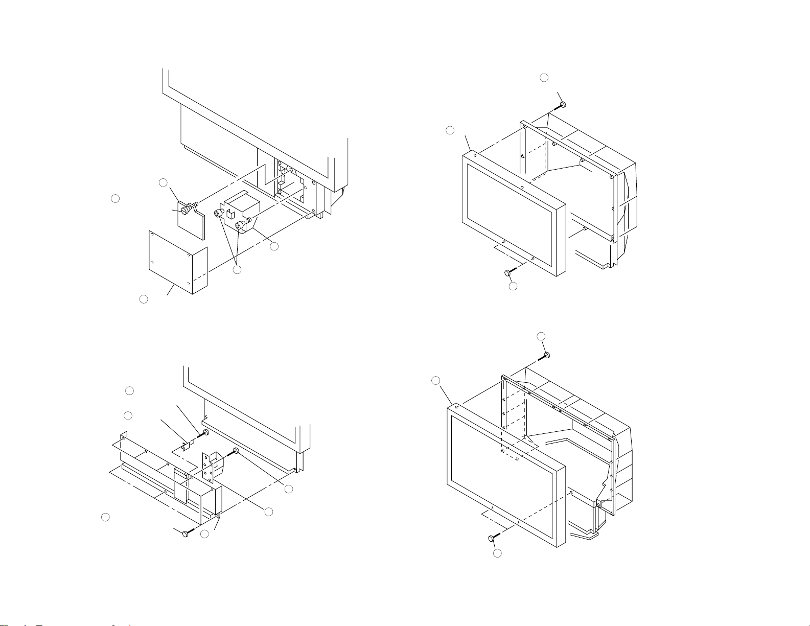
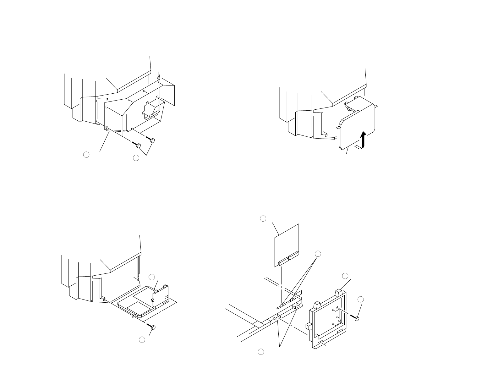
2-7. LAMP REMOVAL 2-9-1. SCREEN FRAME REMOVAL [W7000]
Lamp door
3
Screw
(Ornamental
screw B)
2
Front panel (R)
1
Lamp
5
Two screws
(Hexagon socket bolt 4 x 12)
4
Two screws
(+BVTP 4 x 16)
1
Screen frame
3
Eight screws
(+BVTP 4 x 16)
2
Two screws
(+BVTP 3 x 12)
5
HB board
6
Eight screws
(+BVTP 4 x 16)
1
Front cover
2
HA board
4
Six screws
(+BVTP 3 x 12)
3
Sixteen screws
(+BVTP 4 x 16)
2
Screen frame
3
Two screws
(+BVTP 4 x 16)
1
– 20 –
2-9-2. SCREEN FRAME REMOVAL [W9000]2-8. HA AND HB BOARDS REMOVAL
Page 21
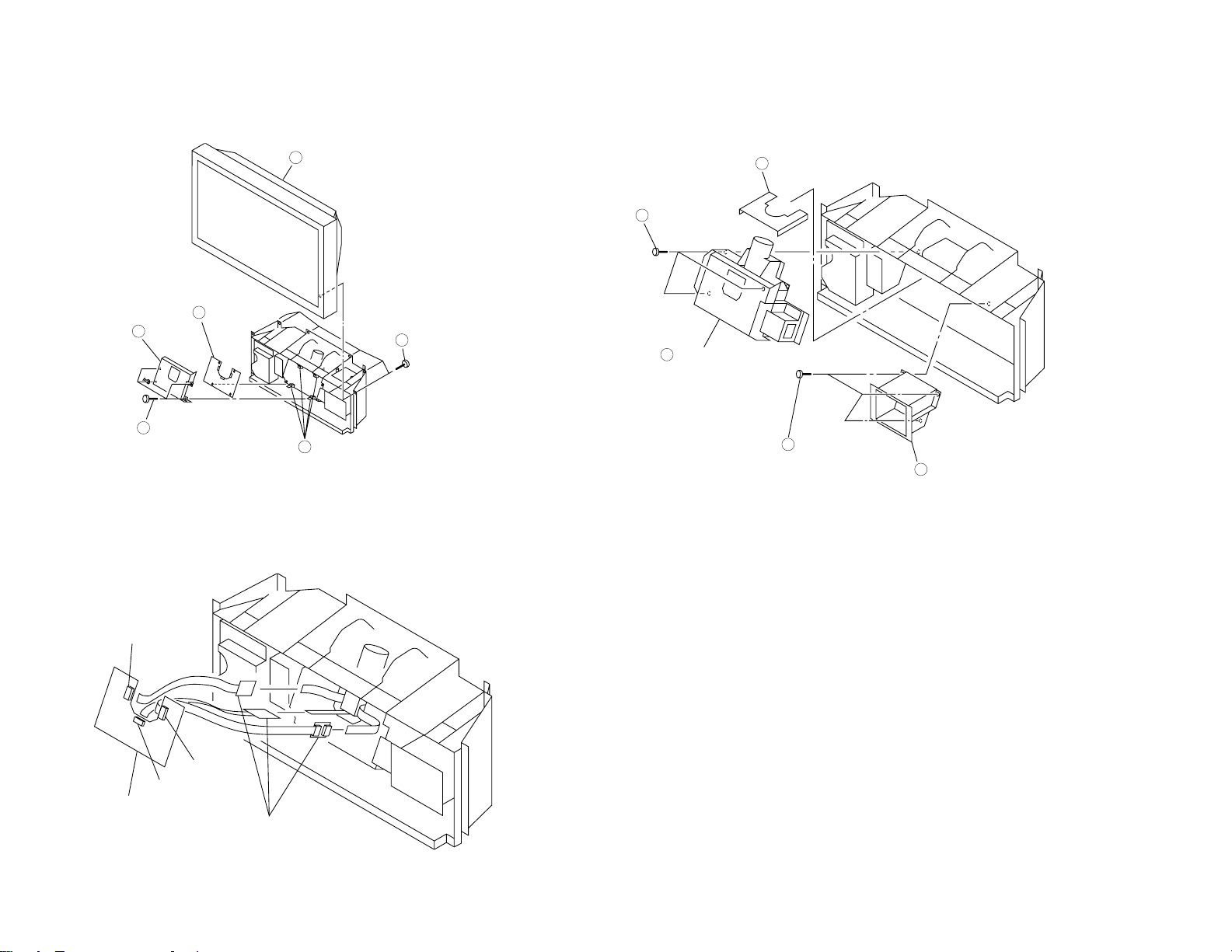
2-10-1. C BOARD REMOVAL 2-11.OPTICAL UNIT REMOVAL
Screen mirror
block
2
Six screws
(+BVTP 4 x 16)
1
Four printed circuit
board holders
5
Four screws
(+BVTP 3 x 12)
3
C cover
4
C board
6
CN5003
CN5001
CN5002
C board
Extension cable
Optical shield
1
Three screws
(+BVTP 4 x 16)
4
Optical unit
5
Three screws
(+BVTP 4 x 16)
2
Lamp base
3
– 21 –
2-10-2. EXTENSION CABLE (C BOARD)
Page 22
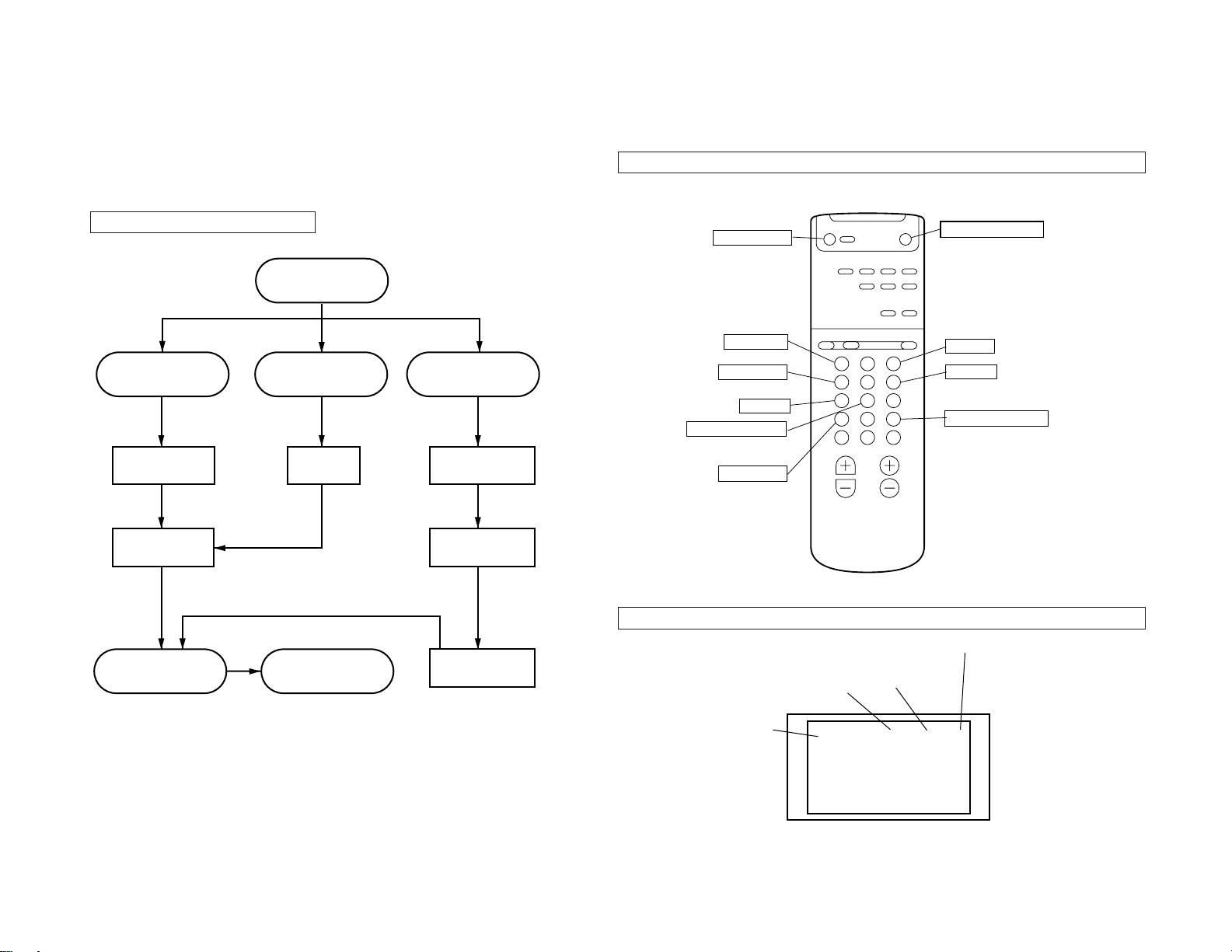
SECTION 3
É
Item No. up
Item No. down
Write standard values
Press !™ successively.
Press !™ successively.
Read memory
Write in memory
Press !™ successively.
Item feed
Execute reading/writing
Data down
Data up
Quit SERVICE mode
CIRCUIT ADJUSTMENTS
KL-W7000/W9000
RM-Y980
ELECTRICAL ADJUSTMENT IN SERVICE MODE
The SERVICE mode cannot be entered with the remote commander RM-Y980 attached to
this set. Use the commander of other TV set.
Adjustment in SERVICE mode
– 22 –
If memory IC 1103
were replaced
Write “standard
values”
Adjust all items
Write in memory
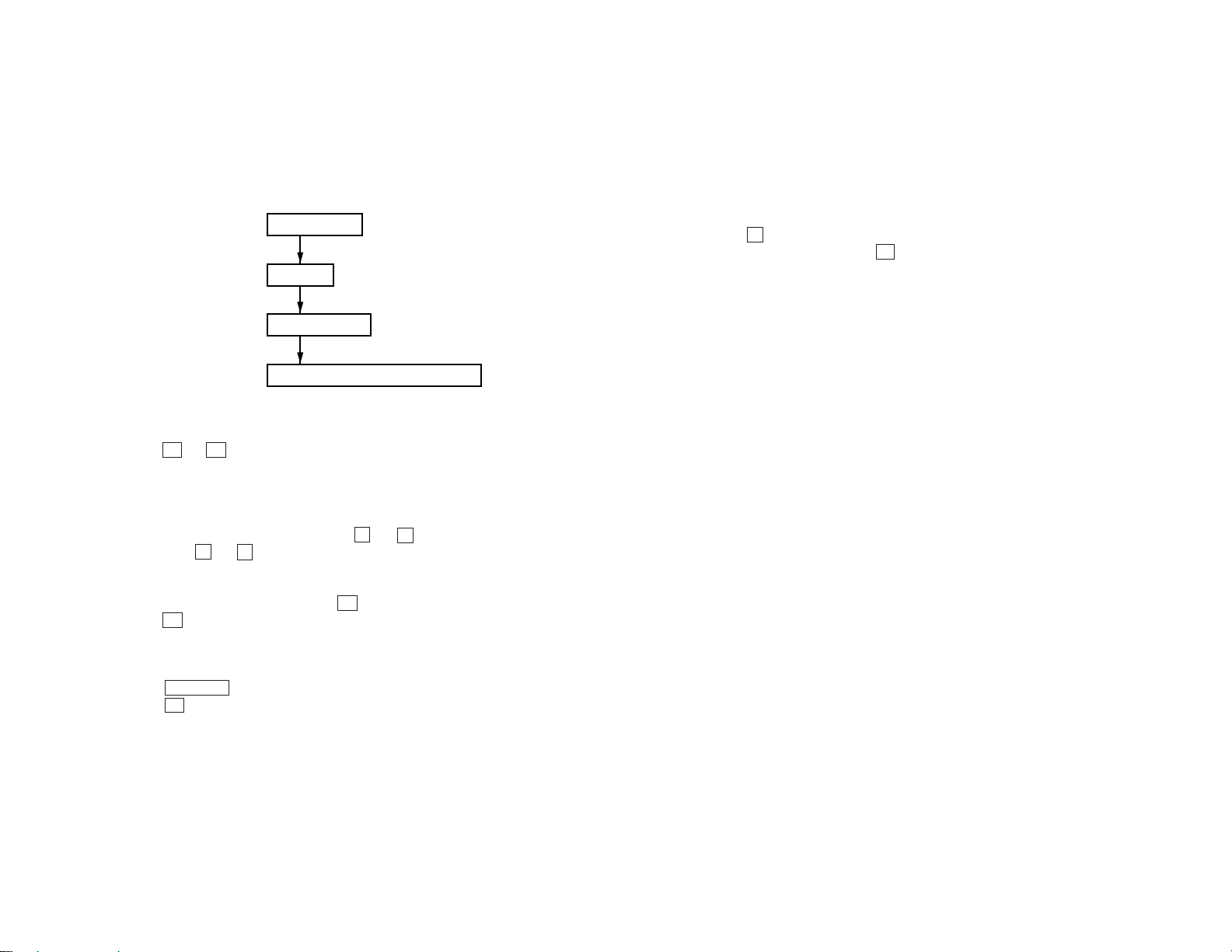
Enter SERVICE Mode
Replace board
A board
Release SERVICE
mode
If repair concerning
picture quality was
executed
Replace LCD
Adjust registration
W/B, screen
position
Function of commander in SERVICE mode
* Example of SERVICE mode using the commander of other TV set
BS
1 3
2
4 5 6
7 8 9
11 12
10
14
1513
Screen in SERVICE mode
Memory reading status
Item No.
Data
Note: • Write data in the memory each time when one item was adjusted.
• Adjusted data are not saved if the power is turned off before they are written in the memory.
Item
(register name)
CXZ2011 0 0 0 4 4 G
G: Memory reading normal
NG: Memory reading failed
Page 23
BASIC ADJUSTMENT IN SERVICE MODE
1. To enter SERVICE mode
1) Turn the POWER switch on the TV set “ON”, then make it in standby status with the
remote commander.
2) Operate the remote commander as follows:
Screen display
CH “5”
Volume “+” side
POWER “ON” (remote commander)
2. To read the memory
1) Enter SERVICE mode.
– 23 –
2) Press 10 n 12 buttons on the remote commander, and the adjusted values and set
values of all items written in the memory are read out.
Note: If the memory IC was replaced, do not read the memory before writing standard values.
3. Adjustment of screen
1) Select the item No. to be adjusted using 1 and 4 buttons on the remote commander.
2) Adjust with 3 and 6 buttons so as to satisfy the picture quality and the set values.
6. To write +standard values+
1) Enter SERVICE mode.
2) Press 8 button, and green +STANDARD WRITE+ is displayed at the upper right of
screen. Successively, press 12 button while this characters are displayed (within
about 3 seconds). Green characters change to red +STANDARD WRITE+, then the
screen becomes blank, and after about 5 seconds, the RGB 1 is selected and the operation stops. At this time, green +G+ is displayed. When +standard values+ writing is
executed, the standard data in the microprocessor on the selected channel are written
in the memory. Thus, the initialization is made.
Note: Writing of +standard values+ must be executed initially, only if the memory IC
2008 and 2009 were replaced.
4. To write data in the memory
• After adjustment, press “MUTING” 12 buttons to write data in the memory.
Press 12 button while green “WRITE” is displayed on the screen (within about 3 seconds).
Color of WRITE characters on screen
When MUTING button ON ... .............. Green
When 12 button ON .............................. Red
5. To release SERVICE mode
• Turn off the POWER switch on TV set and again turn it on. As a result, the SERVICE
mode display is cleared and normal TV mode is resumed.
• Or, turn off the POWER switch from the remote commander and again turn on the
POWER switch on the remote commander in the standby status. As a result, the SERVICE mode display is cleared and normal TV mode is resumed.
KL-W7000/W9000
RM-Y980
Page 24
SERVICE LIST
CXA2011Q
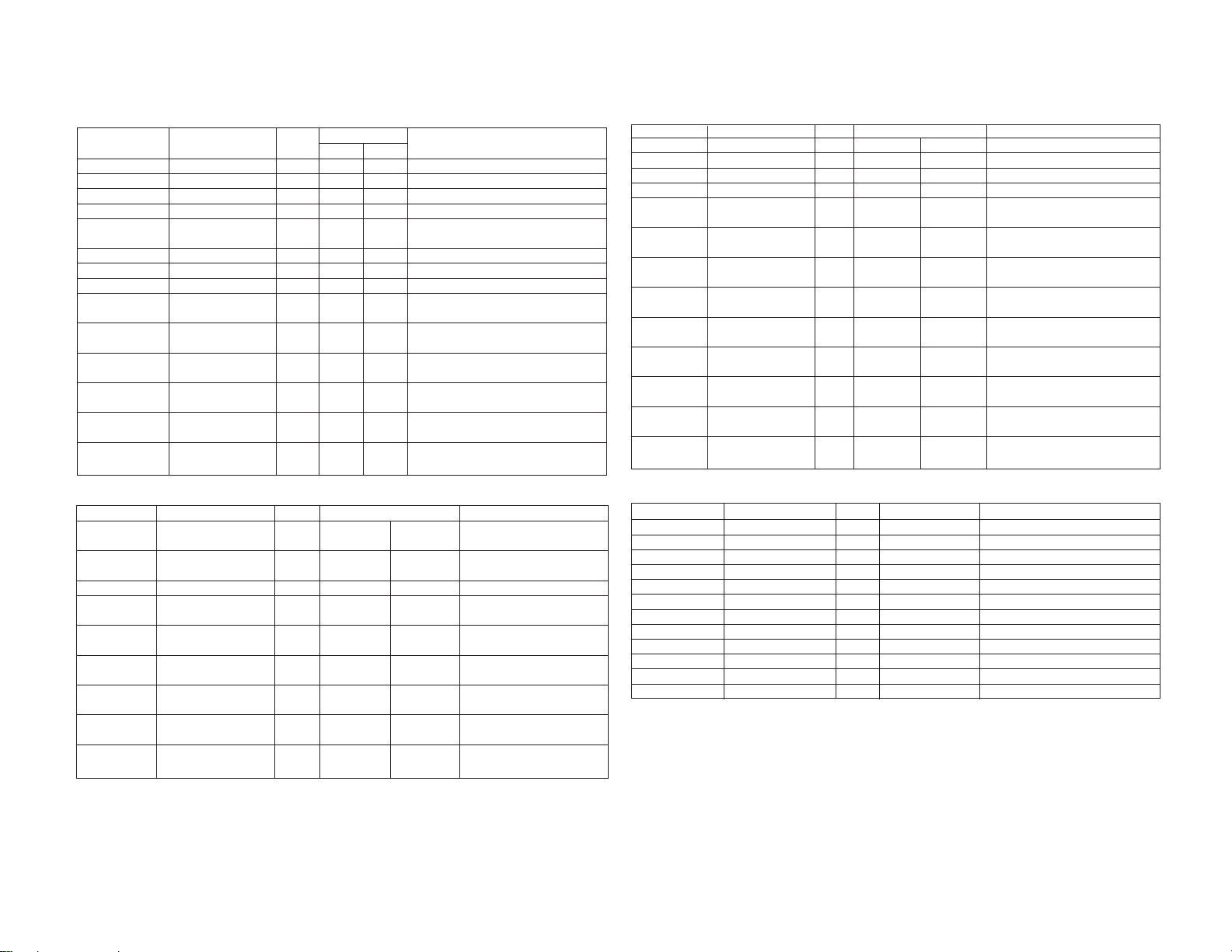
Item Display Register Name Range Stndard Values Typical Standard Values
0 DLVL DRIVE LEVEL 0-63 44 44 2 kinds, RGB 3ch gain control
1 SW2 SW2 0,1 0 0 1 kind
2 SW1 SW1 0,1 0 0 1 kind
3 SW0 SW0 0,1 0 0 1 kind
4 SBOF SUB BRI OFFSET 0-63 23 43 2 kinds. Offset of VIDEO/RGB SUB
5 RDOF R DRIVE OFFSET 0-63 31 31 2 kinds. VIDEO/RGB R DRIVE
6 GDOF G DRIVE OFFSET 0-63 31 31 2 kinds. VIDEO/RGB G DRIVE
7 BDOF B DRIVE OFFSET 0-63 31 31 2 kinds. VIDEO/RGB B DRIVE
8 RDMD R DRIVE OFFSET 0-63 32 32 1 kind. Offset of R color temp.
9 GDMD G DRIVE OFFSET 0-63 31 31 1 kind. Offset of G color temp.
10 BDMD B DRIVE OFFSET 0-63 28 28 1 kind. Offset of B color temp.
11 RDLO R DRIVE OFFSET 0-63 34 34 1 kind. Offset of R color temp. “low”
12 GDLD G DRIVE OFFSET 0-63 31 31 1 kind. Offset of G color temp. “low”
– 24 –
13 BDLO B DRIVE OFFSET 0-63 24 24 1 kind. Offset of B color temp. “low”
(color temp. “middle”) “middle” (center value 31)
(color temp. “middle”) “middle” (center value 31)
(color temp. “middle”) “middle” (center value 31)
(color temp. “low”) (center value 31)
(color temp. “low”) (center value 31)
(color temp. “low”) (center value 31)
VIDEO RGB
BRIGHT 0=–31, · · , 63=+31
BIAS3 (CXA1315)
Item Display Register Name Range Standard Values Typical Standard Values
0 RBS RL_Bias 0-255 0 (VIDEO) 0 (RGB) RL Bias (2 systems of VIDEO, RGB)
1 BLBS RL_Bias 0-255 0 (VIDEO) 0 (RGB) BL Bias (2 systems of VIDEO, RGB)
2 RHBS RL_Bias 0-255 255 (VIDEO) 255 (RGB) RH Bias (2 systems of VIDEO, RGB)
3 BHBS BH_Bias 0-255 255 (VIDEO) 255 (RGB) BH Bias (2 systems of VIDEO, RGB)
4 RLBM RL_Bias off set MID 0-255 131 RL Bias offfset value of color temp.
5 BLBM BL_Bias off set MID 0-255 121 BL Bias offfset value of color temp.
6 RHBM RH_Bias off set MID 0-255 127 RH Bias offfset value of color temp.
7 BHBM BH_Bias off set MID 0-255 127 BH Bias offfset value of color temp.
8 RLBM RL_Bias off set LOW 0-255 136 RL Bias offfset value of color temp.
9 BLBL BL_Bias off set LOW 0-255 115 BL Bias offfset value of color temp.
10 RHBM RH_Bias off set LOW 0-255 127 RH Bias offfset value of color temp.
11 BHBL BH_Bias off set LOW 0-255 127 BH Bias offfset value of color temp.
12 SLSH Sample Phase 0-7
3 (VIDEO 4:3), 3 (RGB 16: 9),
4 (VIDEO 16:9) 4 (RGB 16: 9) (NORMAL, FULL)
“middle” (center value 31)
“middle” (center value 31)
“middle” (center value 31)
“middle” (center value 31)
“low” (center value 31)
“low” (center value 31)
“low” (center value 31)
“low” (center value 31)
4 kinds of SLSH (VIDEO, RGB) ×
KL-W7000/W9000
RM-Y980
WB (CXA1315)
Item Display Register Name Range Standard Values Typical Standard Values
0 RCOI Red Cut Off 0-255 124 (VIDEO) 124 (RGB) 2 kinds : Red white
balance (VIDEO, RGB)
1 RCOI Green Cut Off 0-255 124 (VIDEO) 124 (RGB) 2 kinds : Green white balance
(GCO center)
2 BCOI Blue Cut Off 0-255 124 (VIDEO) 124 (RGB) 2 kinds : Blue white balance
3 RCOM Red Cut Off OFFSET 0-255 132 Red W/B of color temp.
(color temp. “middle”) “middle” (center value 31)
4 GCOM Green Cut Off OFFSET 0-255 127 Green W/B of color temp.
(color temp. “middle”) “middle” (center value 31)
5 BCOM Blue Cut Off OFFSET 0-255 123 Blue W/B of color temp.
(color temp. “middle”) “middle” (center value 31)
6 RCOL Red Cut Off OFFSET 0-255 138 Red W/B of color temp. “low”
(color temp. “low”) (center value 31)
7 RCOL Green Cut Off OFFSET 0-255 127 Green W/B of color temp.
(color temp. “low”) “low” (center value 31)
8 BCOL Blue Cut Off OFFSET 0-255 118 Blue W/B of color temp.
(color temp. “low”) “low” (center value 31)
A_OUT (NVM A2 DATA)
Item Display Register Name Range Standard Values Typical Standard Values
0 RDON NTSC RDOF 0-63 31 NVM A2 Data of address 00
1 GDON NTSC GDOF 0-63 31 Data of address 01
2 BDON NTSC BDOF 0-63 31 Data of address 02
3 RCON NTSC RCOI 0-255 124 Data of address 03
4 GCON NTSC GCOI 0-255 124 Data of address 04
5 BCON NTSC BCOI 0-255 31 Data of address 05
6 RDOH HD RDOF 0-63 31 Data of address 06
7 GDON HD GDOF 0-63 31 Data of address 07
8 BDON HD BDOF 0-63 31 Data of address 08
9 RCON HD RCOI 0-255 124 Data of address 0B
10 GCOH HD GCOI 0-255 124 Data of address 0A
11BCOH HD BCOI 0-255 124 Data of address 09
Page 25
– 25 –
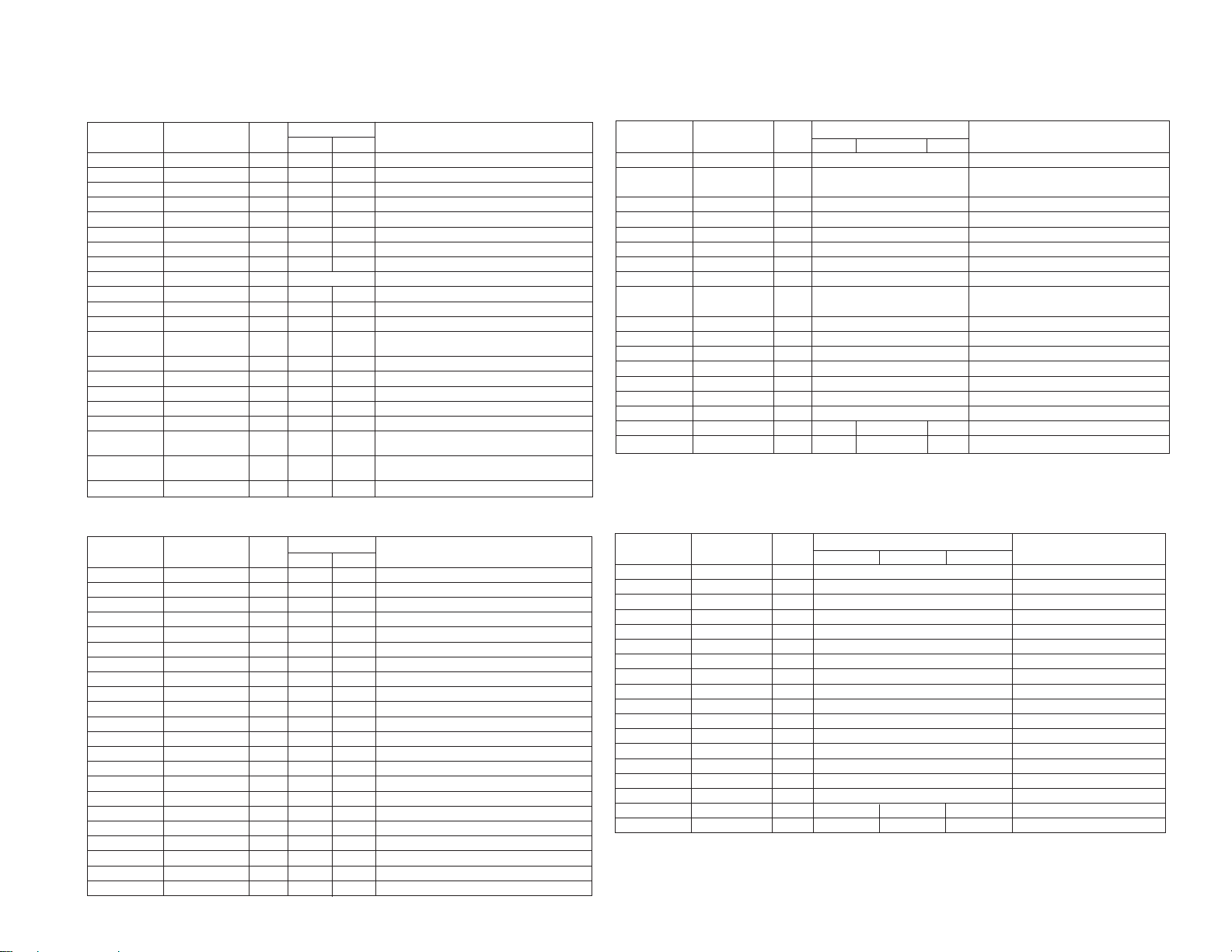
CXA1839
Item Display Register Name Range
0 SHUE SUB-HUE 0-15 8 8 2 kinds (VIDEO, RGB)
1 SBRT SUB-BRT 0-15 8 8 2 kinds (VIDEO, RGB)
2 R-Y/R R-Y/R 0-15 0 0 2 kinds (VIDEO, RGB)
3 R-Y/B R-Y/B 0-15 8 15 2 kinds (VIDEO, RGB)
4 G-Y/R G-Y/R 0-15 15 15 2 kinds (VIDEO, RGB)
5 G-Y/B G-Y/B 0-15 8 0 2 kinds (VIDEO, RGB)
6 SPC2 SUB-CON2 0-15 8 8 2 kinds (VIDEO, RGB)
7 SCL2 SUB-COL2 0-15 8 8 2 kinds (VIDEO, RGB)
8 RGB2 RGB2_LEVEL 0-15 11 1 kind
9 SSHP SUB-SHP 0-3 3/3 1 4 kinds (VIDEO, RGB) × (NORMAL, WIDE)
10 SHPF SHP-F0 0-3 2/2 1 4 kinds (VIDEO, RGB) × (NORMAL, WIDE)
11 PREL PRE_OVER 0-3 3/3 3 4 kinds (VIDEO, RGB) × (NORMAL, WIDE)
12 Y-DC DC-TRAN 0-15 0 0 2 kinds, transmission rate of DC. (VIDEO,
13 DPIX DYNAMIC-PIC 0-3 0 0 2 kinds, Auto pedestal. (VIDEO, RGB)
14 CECL CEC_LEVEL 0-3 3 1 2 kinds, Chroma edge clear. (VIDEO, RGB)
15 RHUE RGB HUE 0-63 – 31 1 kind, Hue adjustment at RGB input.
16 RCOL RGB COLOR 0-63 – 31 1 kind, Color adjustment at RGB input.
17 RSHP
18 SHPP
19 SHPS SHARP 0-63 31 25 1 kind, AI mode, STANDARD sharpness
20 SHPM SHARP MOVIE 0-63 27 31 1 kind, AI mode, MOVIE sharpness value
RGB SHAPNESS
SHARP PRESEN.
STANDARD value
Standard Values
VIDEO RGB
0-63 – 25 1 kind, Sharpness adjustment at RGB input.
0-63 35 25 1 kind, AI mode, PRESENTATION
Typical Standard Values
RGB)
sharpness value
3C (3-Dimensional Com µPD6487)
Item Display Register Name Range Standard Values Typical Standard Values
0 MS MSI, MSO 0-3 0 00 00 : Normal, 01 : 2D, 10 : 3D
1 BPFS BPFS 0-1 0 0 0 : Normal,
2 YDLL YDELAYL 0-7 2/2 1 Kind Output delay designation
3 HRD HRD8-1 0-255 21 21 (2Ah) 21 (2A) : B lock only
4 DYCO DYCOR 0-15 5/5 1 Kind DY detection coaring level
5 DYGA DYGAIN 0-15 8/8 1 Kind DY detection gain
6 DCCO DCCOR 0-15 5/5 1 Kind DC detection coaring level
7 DCGA DCGAIN 0-15 6/6 1 Kind DC detection gain
8 VTR VTR1, VTR0 0-3 0 00 00 : Normal, 01 : Standard,
9 VTRR VTRR 0-31 7/7 1 Kind VTR detection level
10 LDS LDSOFF 0-1 0 0 LD still detect selection
11 HSDR HSDR 0-31 7/7 1 Kind Sync detection level
12 BSDR BSDR 0-31 7 7 Sync detection level
13 WSCO WSCOR 0-7 7/7 1 Kind Weak field detection coaring level
14 WSD1 WSDR1 0-15 15/15 1 Kind Weak field detection level 1
15 WSD2 WSDR2 0-15 15/15 1 Kind Weak field detection level 2
16 VAPG VAPGAIN 0-7 4/4 7/7 0/0 2 Kinds V aperture gain *1
17 VAPI VAPINV 0-31 12/12 20/20 12/12 2 Kinds V aperture inversion point *1
Others
PRESENTATION
MOVIE
1 : Band-pass YC separation
10 : Non-Standard
*1 : 6 kinds of (STANDARD/AV MEMORY, PRESENTATION, MOVIE) × (NORMAL/FULL,
OTHERS)
CXD2052 (Digital Chroma Decoder)
Item Display Register Name Range
0 ACR ACR 0-255 53 35h
1 AKO AKO 0-255 20 24h
2 AKF AKF 0-255 50 32h
3 PKO PKO 0-255 252 FCh
4 PKF PKF 0-255 16 10h
5 OFS OFS 0-255 128 80h
6 BPF1 BPF1 0-1 0(C) 1(S) 2 kinds of S/COMP
7 BPF2 BPF2 0-1 0(C) 0(S) 2 kinds of S/COMP
8 TRAP TRAP 0-1 0 0
9 HPF HFP 0-7
10 FCP FCOP 0-1 0 0
11 DCON DCON 0-1 0 0
12 F2CC F2CCH 0-1 0 0
13 EDTV EDTV 0-1 1 1
14 KILL KILL 0-1 0 0
15 APCO APCOF 0-1 0 0
16 XFH XFH 0-1 0
17 XFH XFH 0-1 0(C) 0(S) 2 kinds of S/COMP
18 TA TA 0-31 16 1ch
19 TB TB 0-63 38(C) 58(C) 2 kinds of S/COMP
20 TO TO 0-63 42(C) 55(C) 2 kinds of S/COMP
21 TE TB 0-63 23(C) 55(S) 2 kinds of S/COMP
Standard Values
VIDEO RGB
4(VIDEO)
Typical Standard Values
2 kinds of VIDEO/RGB
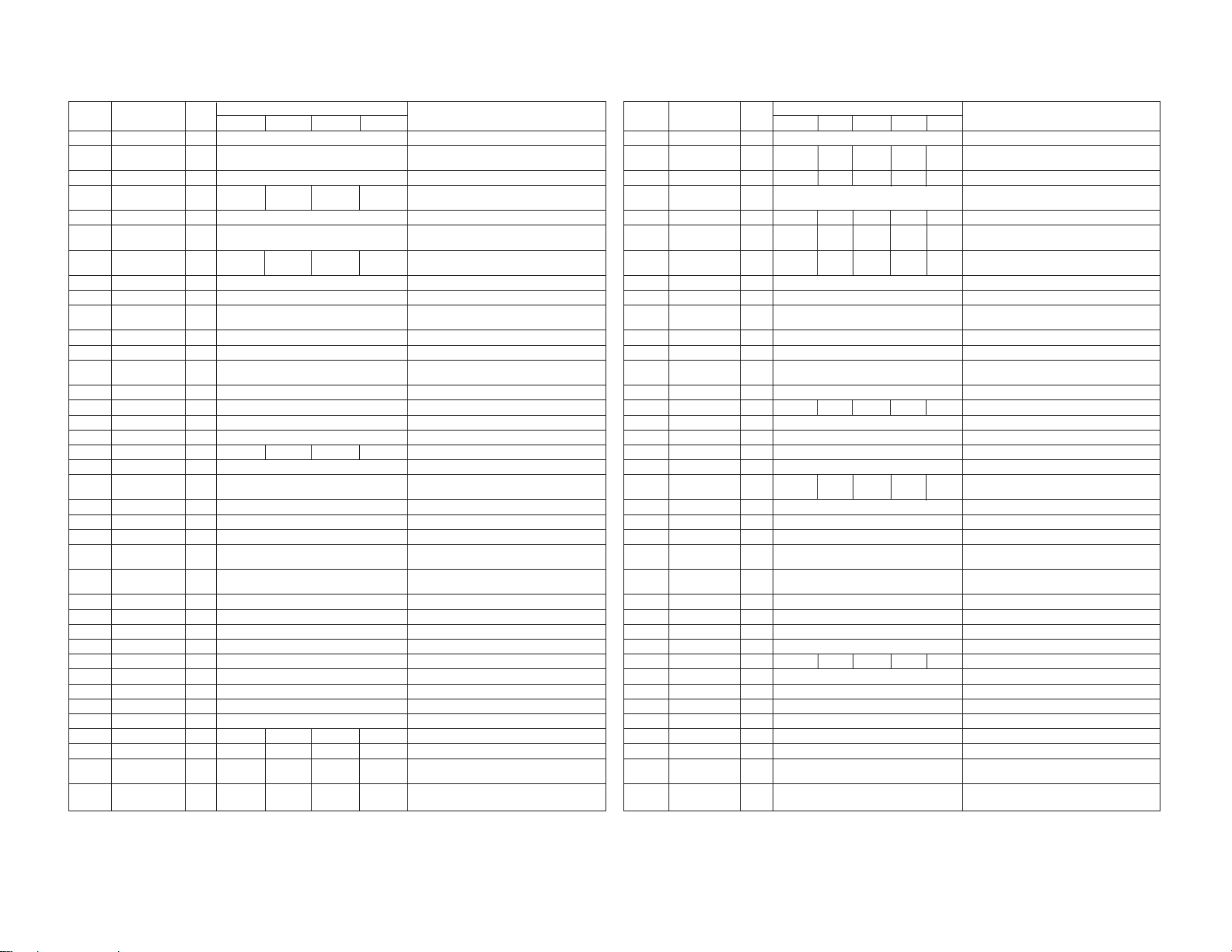
1C (3-Dimensional Com µPD6486)
Item Display Register Name Range Standard Values Typical Standard Values
Others Presen. Movie
0 MS MS1, MS0 0-3 0
1 BPFS BPFS 0-1 0
2 YDLL YDELAYL 0-7 2/2
3 HRD HRD8-1 0-256 21
4 DYCO DYCOR 0-15 5/5
5 DYGA DYGAIN 0-15 8/8
6 DCCO DCCOR 0-15 5/5
7 DCGA DCGAIN 0-15 6/6
8 VTR VTR1, VTR0 0-3 0
9 VTRR VTRR 0-31 7/7
10 LDS LDSOFF 0-1 0
11 HSDR HSDR 0-31 7/7
12 BSDR BSDR 0-31 7
13 WSCO WSCOR 0-7 7/7
14 WSD1 WSDR1 0-15 15/15
15 WSD2 WSDR2 0-15 15/15
16 VAPG VAPGAIN 0-7 4/4 7/7 0/0 NORMAL, FULL/OTHERS
17 VAPI VAPINV 0-31 12/12 20/20 12/12 NORMAL, FULL/OTHERS
KL-W7000/W9000
RM-Y980
Page 26
KL-W7000/W9000
RM-Y980
MID2 (CXD2072Q VIDEO )
Item Register Range Standard Values Typical Standard Values
Display Name
0 HSIZ HSIZEA 0-255 88 Every input signal: H size adj. (NTSC)
1 VGAH VGAHS 0-127 0 Every input signal polarity + Wide screen: H
2 HPOS HPOSIA 0-255 36 Every input signal: H position adj. (READ)
3 VSIZ VSIZEA 0-255 F0 38 0 0 Every input signal polarity + Wide screen: V
4 VPOS VPOSIA 0-255 28 Every input signal: V position adj. (READ)
5 HPHS HPHASA 0-255 44 Every input signal polarity + Wide screen: H
6 VPHS VPHASA 0-255 0A 17 17 0F Every input signal polarity + Wide screen: V
7
WONA
8 OSCA OSCA 0-1 1 Every input signal: Masking range switching
9 DLYA DELAYA 0-7 3 Every input signal: Color difference delay adj.
10
HVSW
11YSDY YSDY 0-7 2 Every input signal: YS delay adj.
12DLY DELAY 0-7 4 Every input signal: Color difference delay
13HBLK HBLK 0-255 89 Every input signal: H blanking adj.
14VBLK VBLK 0-255 1F Every input signal: V blanking adj.
15IPVA IPVA 0-1 0 Every input signal: Vertical linear interpolation
– 26 –
16OFST OFFSET 0-255 0
17VSCA VSCA 0-1 0 1 1 1 Every input signal: A ch vertical size
18OSVA OSVA 0-1 1 Every input signal: A ch vertical offset
19PLL1 PLL1 0-7 0 Every input signal: PLL 1 frequency dividing
20YUV YUV 0-3 0 Every input signal: YUV signal sampling ratio
21REF REF 0-7 0 Every input signal: V size reference value
22CLPD CLPDA 0-255 28 Every input signal: A ch clamp position adj.
23HPH0 bit 0 of HPHASA 0-1 0 Every input signal polarity + Wide screen: H
24HPH0 bit 0 of VPHASA 0-1 0 Every input signal polarity + Wide screen: V
25HCOF H CENT OF. 0-63 – Every input signal: H center offset
26H0OF bit 0 of H CENT OF.0-1 – Every input signal: H center offset (bit 0)
27VCOF V CENT OF. 0-63 – Every input signal: V center offset
28V0OF
29HSOF H SIZE OF. 0-63 – Every input signal: H size offset
30VSOF V SIZE OF. 0-255 – Every input signal: V size offset
31HPR3 HPOSIA REF3 0-255 – HPOSIA value when REF=3 of user preset signal
32HPR4 HPOSIA REF4 0-255 – HPOSIA value when REF=4 of user preset signal
33HPR5 HPOSIA REF5 0-255 – HPOSIA value when REF=5 of user preset signal
34SCOF V SCROLL OF. 0-31 – 0A 0A 0A Every wide screen: V scroll offset
35S0OF
36SCRS V SCROLL 0-63 – 17 17 0F Every wide screen: V scroll standard value
37S0RS
WONA 0-1 0 Every input signal: MOVIE/STILL switching
HVSW 0-3 2 Every input signal: Output Sync signal switching
bit 0 of V CENT OF.
bit 0 of V SCROLL OF.
Standard value
bit 0 of V SCROLL0-1 – 0 0 0 Every wide screen: V scroll standard value (bit 0)
Standard value
NORMAL/FULL
0-1 – Every input signal: V center offset (bit 0)
0-1 – 0 0 0 Every wide screen: V scroll offset (bit 0)
ZOOM SUBTITLE
WIDEZOOM
size adj. (RGB)
size adj.
posi adj. (WRITE)
posi adj. (WRITE)
(INPUT)
adj. (OUTPUT)
Every input signal: Linear interpolation offset setting
ratio setting
posi adj. (WRITE)
posi adj. (WRITE)
MID2 (CXD2072Q RGB (1) )
Item Register Range Standard Values Typical Standard Values
Display Name VGAT350 VGAG W-VGA VGA72 VGA75
0 HSIZ HSIZEA 0-255 A0 Every input signal: H size adj. (NTSC)
1 VGAH VGAHS 0-127 2F 30 2E 2F 2B Every input signal polarity + Wide screen: H
2 HPOS HPOSIA 0-255 2E 2E 2D 2E 2A Every input signal: H position adj. (READ)
3 VSIZ VSIZEA 0-255 3 Every input signal polarity + Wide screen: V
4 VPOS VPOSIA 0-255 38 1E 1E 1E 1E Every input signal: V position adj. (READ)
5 HPHS HPHASA 0-255 42 42 43 4E 52 Every input signal polarity + Wide screen: H
6 VPHS VPHASA 0-255 3 8 8 6 0 Every input signal polarity + Wide screen: V
7
WONA
8 OSCA OSCA 0-1 1 Every input signal: Masking range switching
9 DLYA DELAYA 0-7 3 Every input signal: Color difference delay adj.
10HVSW HVSW 0-3 1 Every input signal: Output Sync signal switching
11YSDY YSDY 0-7 1 Every input signal: YS delay adj.
12DLY DELAY 0-7 4 Every input signal: Color difference delay
13HBLK HBLK 0-255 A0 Every input signal: H blanking adj.
14VBLK VBLK 0-255 0A 30 30 30 30 Every input signal: V blanking adj.
15IPVA IPVA 0-1 0 Every input signal: Vertical linear interpolation
16OFST OFFSET 0-255 0
17VSCA VSCA 0-1 1 Every input signal: A ch vertical siz
18OSVA OSVA 0-1 1 Every input signal: A ch vertical offset
19PLL1 PLL1 0-7 4 4 4 5 5 Every input signal: PLL 1 frequency dividing
20YUV YUV 0-3 1 Every input signal: YUV signal sampling ratio
21REF REF 0-7 5 Every input signal: V size reference value
22CLPD CLPDA 0-255 6A Every input signal: A ch clamp position adj.
23HPH0 bit 0 of HPHASA 0-1 0 Every input signal polarity + Wide screen: H
24VPH0 bit 0 of VPHASA 0-1 0 Every input signal polarity + Wide screen:
25HCOF H CENT OF. 0-63 26 Every input signal: H center offse
26H0OF
27VCOF V CENT OF. 0-63 0 Every input signal: V center offset
28V0OF bit 0 of V CENT OF.
29HSOF H SIZE OF. 0-63 1F 20 20 1F 1B Every input signal: H size offset
30VSOF V SIZE OF. 0-255 EB Every input signal: V size offset
31HPR3 HPOSIA REF3 0-255 28 HPOSIA value when REF=3 of user preset signal
32HPR4 HPOSIA REF4 0-255 25 HPOSIA value when REF=4 of user preset signal
33HPR5 HPOSIA REF5 0-255 28 HPOSIA value when REF=5 of user preset signal
34SCOF V SCROLL OF. 0-31 – Every wide screen: V scroll offset
35S0OF
36SCRS V SCROLL 0-63 – Every wide screen: V scroll standard value
37S0RS
WONA 0-1 0 Every input signal: MOVIE/STILL switching
bit 0 of H CENT OF.
bit 0 of V SCROLL OF.
Standard value
bit 0 of V SCROLL
Standard value
0-1 0 Every input signal: H center offset (bit 0
0-1 0 Every input signal: V center offset (bit 0)
0-1 – Every wide screen: V scroll offset (bit 0)
0-1 – Every wide screen: V scroll standard value(bit 0)
size adj. (RGB)
size adj.
posi adj. (WRITE)
posi adj. (WRITE)
(INPUT)
adj. (OUTPUT)
Every input signal: Linear interpolation offset setting
ratio setting
posi adj. (WRITE)
posi adj. (WRITE)
Page 27
MID2 (CXD2072Q RGB (2) )
Item Register Range Standard Values Typical Standard Values
Display Name VGA85 SVGA56 SVGA60 W-SVGA SVGA72
0 HSIZ HSIZEA 0-255 A0 Every input signal: H size adj. (NTSC)
1 VGAH VGAHS 0-127 2F 26 1A 18 1F Every input signal polarity + Wide screen: H
2 HPOS HPOSIA 0-255 2E 2A 27 27 28 Every input signal: H position adj. (READ)
3 VSIZ VSIZEA 0-255 3 F0 F0 F0 F0 Every input signal polarity + Wide screen: V
4 VPOS VPOSIA 0-255 1D 1F 1F 1F 1F Every input signal: V position adj. (READ)
5 HPHS HPHASA 0-255 3D 45 48 4C 3D Every input signal polarity + Wide screen: H
6 VPHS VPHASA 0-255 4 7 8 8 9 Every input signal polarity + Wide screen: V
7 WONA WONA 0-1 0 Every input signal: MOVIE/STILL switching
8 OSCA OSCA 0-1 1 Every input signal: Masking range switching
9 DLYA DELAYA 0-7 3 Every input signal: Color difference delay
10HVSW HVSW 0-3 1 Every input signal: Output Sync signal switching
11YSDY YSDY 0-7 1 Every input signal: YS delay adj.
12DLY DELAY 0-7 4 Every input signal: Color difference delay
13HBLK HBLK 0-255 A0 Every input signal: H blanking adj.
14VBLK VBLK 0-255 30 Every input signal: V blanking adj.
15IPVA IPVA 0-1 0 Every input signal: Vertical linear interpolation
– 27 –
16OFST OFFSET 0-255 0
17VSCA VSCA 0-1 1 0 0 0 0 Every input signal: A ch vertical size
18OSVA OSVA 0-1 1 Every input signal: A ch vertical offset
19PLL1 PLL1 0-7 5 4 4 4 4 Every input signal: PLL 1 frequency dividing
20YUV YUV 0-3 1 Every input signal: YUV signal sampling ratio
21REF REF 0-7 5 2 2 2 2 Every input signal: V size reference value
22CLPD CLPDA 0-255 6A Every input signal: A ch clamp position adj.
23HPH0 bit 0 of HPHASA 0-1 1 1 0 0 0 Every input signal polarity + Wide screen: H
24HPH0 bit 0 of VPHASA 0-1 0 0 1 1 1 Every input signal polarity + Wide screen: V
25HCOF H CENT OF. 0-63 26 Every input signal: H center offset
26H0OF
bit 0 of H CENT OF.
27VCOF V CENT OF. 0-63 0 Every input signal: V center offset
28V0OF bit 0 of V CENT OF.
29HSOF H SIZE OF. 0-63 1F 16 0A 0A 0F Every input signal: H size offset
30VSOF V SIZE OF. 0-255 EB E7 E7 E7 E7 Every input signal: V size offset
31HPR3 HPOSIA REF3 0-255 28 HPOSIA value when REF=3 of user preset signal
32HPR4 HPOSIA REF4 0-255 25 HPOSIA value when REF=4 of user preset signal
33HPR5 HPOSIA REF5 0-255 28 HPOSIA value when REF=5 of user preset signal
34SCOF V SCROLL OF. 0-31 – Every wide screen: V scroll offset
35S0OF
bit 0 of V SCROLL OF.
36SCRS V SCROLL 0-63 – Every wide screen: V scroll standard value
Standard value
37S0RS
bit 0 of V SCROLL
Standard value
0-1 1 1 0 0 0 Every input signal: H center offset (bit 0)
0-1 0 0 1 1 1 Every input signal: V center offset (bit 0)
0-1 – Every wide screen: V scroll offset (bit 0)
0-1 – Every wide screen: V scroll standard value(bit 0)
size adj. (RGB)
size adj.
posi adj. (WRITE)
posi adj. (WRITE)
adj. (INPUT)
adj. (OUTPUT)
Every input signal: Linear interpolation offset setting
ratio setting
posi adj. (WRITE)
posi adj. (WRITE)
MID2 (CXD2072Q RGB (3) )
Item Register Range Standard Values Typical Standard Values
Display Name SVGA75 XGA60 W-XGA MAC13 MAC16
0 HSIZ HSIZEA 0-255 A0 Every input signal: H size adj. (NTSC)
1 VGAH VGAHS 0-127 1A 1D 1C 2F 9 Every input signal polarity + Wide screen: H
2 HPOS HPOSIA 0-255 28 26 26 2E 24 Every input signal: H position adj. (READ)
3 VSIZ VSIZEA 0-255 F0 F0 F0 3 F0 Every input signal polarity + Wide screen: V
4 VPOS VPOSIA 0-255 1F 1F 1F 1E 1F Every input signal: V position adj. (READ)
5 HPHS HPHASA 0-255 51 4C 4C 4A 59 Every input signal polarity + Wide screen: H
6 VPHS VPHASA 0-255 7 8 8 0B 0F Every input signal polarity + Wide screen: V
7 WONA WONA 0-1 0 Every input signal: MOVIE/STILL switching
8 OSCA OSCA 0-1 1 Every input signal: Masking range switching
9 DLYA DELAYA 0-7 3 Every input signal: Color difference delay
10HVSW HVSW 0-3 1 Every input signal: Output Sync signal switching
11YSDY YSDY 0-7 1 Every input signal: YS delay adj.
12DLY DELAY 0-7 4 Every input signal: Color difference delay
13HBLK HBLK 0-255 A0 Every input signal: H blanking adj.
14VBLK VBLK 0-255 30 Every input signal: V blanking adj.
15IPVA IPVA 0-1 0 Every input signal: Vertical linear interpolation
16OFST OFFSET 0-255 0
17VSCA VSCA 0-1 0 0 0 1 0 Every input signal: A ch vertical size
18OSVA OSVA 0-1 1 Every input signal: A ch vertical offset
19PLL1 PLL1 0-7 4 4 4 6 4 Every input signal: PLL 1 frequency dividing
20YUV YUV 0-3 1 Every input signal: YUV signal sampling ratio
21REF REF 0-7 2 4 4 5 3 Every input signal: V size reference value
22CLPD CLPDA 0-255 6A 6A 6A 40 6A Every input signal: A ch clamp position adj.
23HPH0 bit 0 of HPHASA 0-1 1 0 0 0 1 Every input signal polarity + Wide screen: H
24VPH0 bit 0 of VPHASA 0-1 0 1 1 1 0 Every input signal polarity + Wide screen: V
25HCOF H CENT OF. 0-63 26 26 26 26 2E Every input signal: H center offset
26H0OF
bit 0 of H CENT OF.
27VCOF V CENT OF. 0-63 0 Every input signal: V center offset
28V0OF
bit 0 of V CENT OF.
29HSOF H SIZE OF. 0-63 0A 0D 0D 1F 0 Every input signal: H size offset
30VSOF V SIZE OF. 0-255 E7 E7 E7 EB E7 Every input signal: V size offset
31HPR3 HPOSIA REF3 0-255 28 HPOSIA value when REF=3 of user preset signal
32HPR4 HPOSIA REF4 0-255 25 HPOSIA value when REF=4 of user preset signal
33HPR5 HPOSIA REF5 0-255 28 HPOSIA value when REF=5 of user preset signal
34SCOF V SCROLL OF. 0-31 – Every wide screen: V scroll offset
35S0OF
bit 0 of V SCROLL OF.
36SCRS V SCROLL 0-63 – Every wide screen: V scroll standard value
Standard value
37S0RS
bit 0 of V SCROLL
Standard value
0-1 1 0 0 0 1 Every input signal: H center offset (bit 0)
0-1 0 1 1 1 0 Every input signal: V center offset (bit 0)
0-1 – Every wide screen: V scroll offset (bit 0)
0-1 – Every wide screen: V scroll standard value(bit 0)
size adj. (RGB)
size adj.
posi adj. (WRITE)
posi adj. (WRITE)
adj. (INPUT)
adj. (OUTPUT)
Every input signal: Linear interpolation offset setting
ratio setting
posi adj. (WRITE)
posi adj. (WRITE)
KL-W7000/W9000
RM-Y980
Page 28

KL-W7000/W9000
RM-Y980
MID2 (CXD2072Q RGB (4) )
Item Register Range Standard Values Typical Standard Values
Display Name VGAT85
0 HSIZ HSIZEA 0-255 A0 Every input signal: H size adj. (NTSC)
1 VGAH VGAHS 0-127 20 1E 1E 2E Every input signal polarity + Wide screen: H
2 HPOS HPOSIA 0-255 26 27 26 2E Every input signal: H position adj. (READ)
3 VSIZ VSIZEA 0-255 3 F0 F0 3 Every input signal polarity + Wide screen: V
4 VPOS VPOSIA 0-255 3A 1E 1E 1E Every input signal: V position adj. (READ)
5 HPHS HPHASA 0-255 41 48 4C 48 Every input signal polarity + Wide screen: H
6 VPHS VPHASA 0-255 6 2 8 5 Every input signal polarity + Wide screen: V
7 WONA WONA 0-1 0 Every input signal: MOVIE/STILL switching
8 OSCA OSCA 0-1 1 Every input signal: Masking range switching
9 DLYA DELAYA 0-7 3 Every input signal: Color difference delay
10HVSW HVSW 0-3 1 Every input signal: Output Sync signal switching
11YSDY YSDY 0-7 1 Every input signal: YS delay adj.
12DLY DELAY 0-7 4 Every input signal: Color difference delay adj.
13HBLK HBLK 0-255 A0 Every input signal: H blanking adj.
14VBLK VBLK 0-255 0C 30 30 30 Every input signal: V blanking adj.
15IPVA IPVA 0-1 0 Every input signal: Vertical linear interpolation
– 28 –
16OFST OFFSET 0-255 0
17VSCA VSCA 0-1 1 0 0 1 Every input signal: A ch vertical size
18OSVA OSVA 0-1 1 Every input signal: A ch vertical offset
19PLL1 PLL1 0-7 4 Every input signal: PLL 1 frequency dividing
20YUV YUV 0-3 1 Every input signal: YUV signal sampling ratio
21REF REF 0-7 5 3 4 5 Every input signal: V size reference value
22CLPD CLPDA 0-255 6A Every input signal: A ch clamp position adj.
23HPH0 bit 0 of HPHASA. 0-1 1 0 0 0 Every input signal polarity + Wide screen: H
24HPH0 bit 0 of VPHASA 0-1 0 Every input signal polarity + Wide screen: V
25HCOF H CENT OF. 0-63 26 33 33 33 Every input signal: H center offset
26H0OF bit 0 of H CENT OF.
27VCOF V CENT OF. 0-63 0 Every input signal: V center offset
28V0OF
bit 0 of V CENT OF.0-1 0 Every input signal: V center offset (bit 0)
29HSOF H SIZE OF. 0-63 10 18 18 18 Every input signal: H size offset
30VSOF V SIZE OF. 0-255 EB E7 E7 EB Every input signal: V size offset
31HPR3 HPOSIA REF3 0-255 28 HPOSIA value when REF=3 of user preset signal
32HPR4 HPOSIA REF4 0-255 25 HPOSIA value when REF=4 of user preset signal
33HPR5 HPOSIA REF5 0-255 28 HPOSIA value when REF=5 of user preset signal
34SCOF V SCROLL OF. 0-31 – Every wide screen: V scroll offset
35S0OF
bit 0 of V SCROLL OF.
36SCRS V SCROLL 0-63 – Every wide screen: V scroll standard value
Standard value
37S0RS
bit 0 of V SCROLL
Standard value
0-1 1 0 0 0 Every input signal: H center offset (bit 0)
0-1 – Every wide screen: V scroll offset (bit 0)
0-1 – Every wide screen: V scroll standard value(bit 0)
OTHERS
REF=3 REF=4 REF=5
size adj. (RGB)
size adj.
posi adj. (WRITE)
posi adj. (WRITE)
adj. (INPUT)
(OUTPUT)
Every input signal: Linear interpolation offset setting
ratio setting
posi adj. (WRITE)
posi adj. (WRITE)
AP (TA8776N)
Item Display Register Name Range Standard Values Typical Standard Values
0 SBAS SUB_BASS 0-63 10 10
1 STRE SUB_TRABLE 0-63 2 2
Page 29
OP (Others)
Item Register Name Range Standard Values Typical Standard Values
Display
0 OSDH Display H Position 0-63 10 (VIDEO) 7(RGB) 2 Kinds (VIDEO, RGB)
1 OSDV Display V Position 0-63 7 (VIDEO) 7(RGB) 2 Kinds (VIDEO, RGB)
2 ASHT Auto Shut Off 0,1 Not used 0: OFF, 1: ON
3 CPWR CH Power ON Not used Not used
4 AGCH AGC Voltage High 0-15 Not used Not used
5 AGCL AGC Voltage Low 0-15 Not used Not used
6 DBSS DBS Category Yes/No Not used Not used
7 EDCK EDTV FULL Mode Detection 0,1 Not used Not used
8 AION AI AUTO 0,1 Not used Not used
9 K Picture Adjusting Variable K 0-7 1 Don't set “0” (Actual value is
10 L Picture Adjusting Variable L 0-7 0 0~7 is converted into 1~8 in actual use.
11 LENS Display only 0 – Lens focus adj.
12 PANEL 0:Green, 1:Red, 2:Blue, 3:White 0-3 – Panel position adj.
13 WHITE APL 0-1 – White balance adj. (0: GAIN, 1: BIAS)
14 WIND Display only 0 – Window signal
15 STEP Display only 0 00: Normal, 01: Pattern 1,
16 EDFL EDTV FULL Detection ON 0,1 Not used Not used
17 BC g_bs_search [0] 1-15 Not used Not used
18 TIME Lamp Counting Timer Current time count and 0 time are
– 29 –
19 FMTL fh of distinction difference range 0 ± ((3+FHTL) ×0.2) kHz
20 FVTL fv of distinction difference range 0 ± (1.0+FVTL) Hz
21HV1 Threshold of scanning line 0-15 (505+ (5×HV1)) lines
22 HV2 Threshold of scanning line 0-15 (555+ (5×HV2)) lines
23 MINH fh of the frequency correspond 0-31 20+ ((3+FHTL) ×0.2) kHz
24 MAXH fh of the frequency correspond 0-31 42+ ((3+FHTL) ×0.2) kHz
25 MINV fv of the frequency correspond 0-15 (42+MINV) Hz
26 MAXV fv of the frequency correspond 0-15 (77+MAXV) Hz
27 FHAG Equivalence frequency of fh 0-15 FHAG (20×FHAGms)
28 FVAG Equivalence frequency of fv 0-15 FHAG (20×FVAGms)
29 NSAG Equivalence frequency of 0-15 Not used
30 FHMJ fh difference range of before 0-7 ± ((1+FHMJ) ×0.2) kHz
31 FVMJ fv difference range of before 0-7 ± ((3+FVMJ)
distinction (low)
distinction (high)
to MIN
to MAX
to MIN
to MAX
changed detection
changed detection
non-signal detection (on signal)
the signal distinction
the signal distinction
1/8~7/8)
02: Pattern 2
displayed alternately with UP/DOWN
TP (Model Discrimination)
Item Display Register Name Range Standard Values Typical Standard Values
0 WIDE HH 0,1 Not used
1 TIME TIMER 0,1 0,1 Fan stop time switching
0: 10 min (normal), 1: 10 sec
2 KL37 KL-W7000 model 0,1 0,1 0: KL-W9000 1: KL-W7000
KL-W7000/W9000
RM-Y980
Page 30

C Board Adjustment
1. PLL fo adjustment
1) WIDE mode
1. Select WIDE mode.
2. Open the CN5202 pin 1, H.SYNC input.
3. Connect *IC5004 pin 2 to the GND (*TP5009) via 100Ω resis-
4. Connect *frequency counter to the pin 1 of *IC5004.
5. Adjust *L5002 so as to satisfy the *specified value.
6. Input H.SYNC for NT double speed, and confirm the wave-
2) NORMAL mode
1. Select NORMAL mode.
2. Open the CN5202 pin 1, H.SYNC input.
3. Connect *IC5004 pin 2 to the GND (*TP5009) via 100Ω resis-
– 30 –
4. Connect *frequency counter to the pin 1 of *IC5004.
5. Adjust *L5004 so as to satisfy the *specified value.
6. Input H.SYNC for NT double speed
7. Confirm the waveform at the *TP5004 with *oscilloscope.
Adjustment Items and Procedure Tools and Test Points Adjustment Places Illustration Waveforms and Values
Signals
* NTSC signal
* IC5004 pin 2
tance.
* Frequency counter
* Double speed NTSC
* Oscilloscope
* TP5009 Jig land
* IC5004
* TP5007 (RPD2)
* L5002
* 13.67±0.10MHz
*
form at the *TP with *oscilloscope.
* NTSC signal
tance.
* Frequency counter
* Double speed NTSC
* Oscilloscope
* IC5004 pin 2
* IC5009
* IC5004 pin 1
* TP5007 (RPD1)
* L5004
* 10.22±0.05MHz
*
Use TP5009 as
reference GND.
2.3±0.3 V
KL-W7000/W9000
RM-Y980
2.39±0.1µs
31.78µs
5.0Vp-p
Use TP5009 as
reference GND.
Page 31
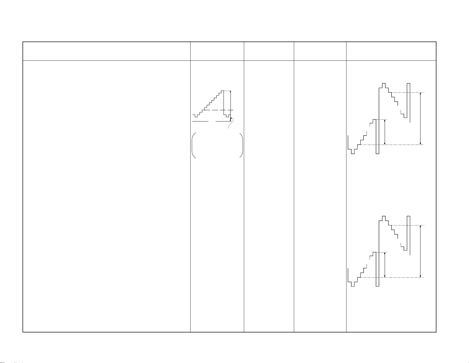
Adjustment Items and Procedure Tools and Test Points Adjustment Places Illustration Waveforms and Values
Signals
2. IC Level Adjustment
1. Using *I
2. Enter NT double speed 10-step signal of bias 2.2V and ampli-
1) R channel
– 31 –
1. Using *DC power, apply 0V to *TP5211.
2. Connect *oscilloscope to *TP5203, and adjust *RV5205 so
3. Adjust *RV5201 so that the forward 10 IRE ~ reverse 10 IRE
4. Confirm that a difference in voltage amplitude of forward 10
2) G channel
1. Using *DC power, apply 0V to *TP5411.
2. Connect *oscilloscope to *TP5403, and adjust *RV5407 so
3. Adjust *RV5403 so that the forward 10 IRE ~ reverse 10 IRE
4. Confirm that a difference in voltage amplitude of forward 10
2
C bus encoder, set the NT-WIDE mode.
tude 1.8Vp-p to the CN5201 pins 2~4.
that 10 IRE ~ 100 IRE (A) becomes *1.35±0.02Vp-p.
(B) becomes *5.70±0.02Vp-p at *TP5203.
IRE ~ 100 IRE and forward 10 IRE ~ reverse 10 IRE between
waveform at *TP5202,*TP5204 and waveform at *TP5203 is
within ±150mV.
that 10 IRE ~ 100 IRE (A) becomes *1.35±0.02Vp-p.
(B) becomes *6.10±0.02Vp-p at *TP5403.
IRE ~100 IRE and forward 10 IRE~ reverse 10 IRE between
waveform at *TP5602, *5604 and waveform at *TP5603 is
within ±150mV.
2
*I
C bus encoder
*
2.0 ± 0.02 Vp-p
GND
2.7 ± 0.02 V
Use TP5201,
TP5401 and TP5601
as reference GND
respectively.
* DC power
* Oscilloscope
* DC power
* Oscilloscope
100 IRE
$
10
IRE
4
* TP5211 [RLBS]
TP5207 is ref. GND
* TP5203 [R-SIG2]
* TP5203 [R-SIG2]
* TP5411 [GLBS]
TP5407 is ref. GND
* TP5202 [R-SIG1]
* TP5204 [R-SIG3]
* TP5203 [R-SIG2]
* TP5403 [G-SIG2]
* TP5403 [G-SIG2]
* TP5402 [G-SIG1]
* TP5404 [G-SIG3]
* TP5403 [G-SIG2]
* RV5205 [R. GAIN]
* RV5201 [R. BIAS]
* RV5407 [G. GAIN]
* RV5403 [G. BIAS]
A
* A : 1.35±0.02Vp-p
* B : 5.70±0.02Vp-p
A
* A : 1.35±0.02Vp-p
* B : 6.10±0.02Vp-p
100 IRE
100 IRE
10 IRE
B
10
10 IRE
B
10
IRE
IRE
KL-W7000/W9000
RM-Y980
Page 32

Adjustment Items and Procedure Tools and Test Points Adjustment Places Illustration Waveforms and Values
Signals
10 IRE
KL-W7000/W9000
RM-Y980
3) B channel
1. Using *DC power, apply 0V to *TP5611.
2. Connect *oscilloscope to *TP5603, and adjust *RV5605 so
3. Adjust *RV5601 so that the forward 10 IRE ~ reverse 10 IRE
– 32 –
4. Confirm that a difference in voltage amplitude of forward 10
4. Vcom Adjustment
• *Using *I
• *Enter NT double speed 10-step signal of *bias 2.2V and amplitude
1.8Vp-p to the CN5201 pins 2~4.
1. Measure voltage at the *TP5203 with digital voltmeter.
2. Adjust *RV5202 so that the voltage at *TP5205 becomes
3. Measure voltage at the *TP5403 with digital voltmeter.
that 10 IRE ~ 100 IRE (A) becomes *1.35±0.02Vp-p.
(B) becomes *5.90±0.02Vp-p at *TP5603.
IRE ~ 100 IRE and forward 10 IRE ~ reverse 10 IRE between
waveform at *TP5602,*TP5604 and waveform at *TP5603 is
within ±150mV.
2
C bus encoder, set the NT-WIDE mode.
*(Value in 1) – 0.60±0.02V.
* DC power
* Oscilloscope
2
C bus encoder
*I
*
2.0 ± 0.02 Vp-p
GND
2.7 ± 0.02 V
Use TP5201,
TP5401 and TP5601
as reference GND
respectively.
* Voltmeter
* Voltmeter
* TP5611 [BLBS]
* TP5607 is Ref.
GND
* TP5603 [B-SIG2]
* TP5603 [B-SIG2]
* TP 5602 [B-SIG1]
* TP5604 [B-SIG3]
* TP5603 [B-SIG2]
100 IRE
$
10
IRE
4
* TP5203 [Rch OUT]
* TP5205 [R-Vcom
OUT]
* TP5403 [Gch OUT]
* RV5605 [B. GAIN]
* RV5601 [B. BIAS]
* RV5202 [R.VCOM]
100 IRE
A
* A : 1.35±0.02Vp-p
* B : 5.90±0.02Vp-p
* (Value in 1) – 0.60±0.02V
B
IRE
10
Page 33

Adjustment Items and Procedure Tools and Test Points Adjustment Places Illustration Waveforms and Values
3. r Curve Adjustment
• C board input signal level setting
1. Using *I2C bus encoder, set the NT-WIDE mode.
2. Enter *NT double speed (10 step) signal of bias 2.2V and amplitude
1.8Vp-p to the CN5201 pins 1~3.
• After adjusting the amplitude of 1.8V, adjust the bias level of
2.2V.
• R channel
1. Connect *oscilloscope to *TP5203.
2. *DC power, apply 3.60±0.02V to *TP5211.
3. Adjust *RV5203 so that 10 IRE ~ 20 IRE becomes *600±20mV.
Adjustment is no good when 0 IRE ~10 IRE voltage is below 100 mV.
4. Confirm that forward 10 IRE ~ reverse 10 IRE voltage is over 6.5V.
• G channel
1. Connect *oscilloscope to *TP5403.
– 33 –
2. *DC power, apply 3.60±0.02V to *TP5411.
3. Adjust *RV so that 10 IRE ~ 20 IRE becomes *700±20mV.
4. Stop the voltage application to *TP5411.
Signals
2
C bus encoder
*I
*
2.0 ± 0.02 Vp-p
GND
2.7 ± 0.02 V
Use TP5201,
TP5401 and TP5601
as reference GND
respectively.
* Oscilloscope
* DC power
100 IRE
$
10
IRE
4
* TP5203 [R-SIG2]
* TP5211 [RLBS]
* TP5207 is Ref. GND
* TP5403 [R-SIG2]
* TP5411 [GLBS]
*RV5403 [RL. GAIN]
20 IRE
10 IRE
*TP5411 [GLBS] *RV5405 [GL.GAIN]
* 10 IRE~20 IRE : 600±20 mV
20 IRE
10 IRE
* 10 IRE~20 IRE : 600±20 mV
KL-W7000/W9000
RM-Y980
Page 34

Adjustment Items and Procedure Tools and Test Points Adjustment Places Illustration Waveforms and Values
10 IRE
10 IRE
100 IRE
10 IRE
B
A
Signals
KL-W7000/W9000
RM-Y980
5. Adjust *RV so that the forward 10 IRE ~ reverse 10 IRE (A) be-
comes *8.30±0.02Vp-p.
Adjustment is no good when 0 IRE ~ 10 IRE voltage is below
100mV.
6. Confirm that forward 100 IRE ~ reverse 100 IRE (B) is
*3.45±0.10Vp-p.
– 34 –
• B channel
1. Connect *oscilloscope to *TP5603.
2. *DC power, apply 3.60±0.02V to *TP5611.
3. Adjust *RV so that 10 IRE ~ 20 IRE becomes *800±20mV.
Confirm that 0 IRE ~ 10 IRE voltage is over 7.1V.
* Oscilloscope
* DC power
* RV5402 [GL. BIAS]
* A : 8.30±0.02Vp-p
* B : 3.45±0.10Vp-p
* TP5603 [B-SIG2]
* TP5411 [GLBS]
20 IRE
10 IRE
* RV5603 [GL. GAIN]
* 10 IRE ~20IRE : F800 : 20mV
Page 35

Adjustment Items and Procedure Tools and Test Points Adjustment Places Illustration Waveforms and Values
Signals
4. Adjust *RV5404 so that the voltage at *TP5405 becomes
*(Value in 3) –0.50±0.02V.
5. Measure voltage at the *TP5603 with digital voltmeter.
6. Adjust *RV5602 so that the voltage at *TP5605 becomes
*(Value in 5) – 0.80±0.02V.
A Board Adjustment
1. Enter *1Vp-p 10-step signal from the Video1 input.
2. Set the user control to the RESET of *AV MEMORY, *PIX to
maximum, and H WHITE to OFF.
3. Connect *oscilloscope to *TP4002.
– 35 –
* Voltmeter
* NTSC 10-step signal
* Oscilloscope
* TP5405 [G.VCOM
OUT]
* TP5603 [Bch OUT]
* TP5605 [B-VCOM
OUT]
* TP4002 [2G]
* RV5404 [G.VCOM]
* RV5602[B.VCOM]
* AV MEMORY
* RESET
* H WHITE OFF
* (Value in 3) – 0.50±0.02V
* (Value in 5) – 0.80±0.02V
100 IRE
0 IRE
0 V
KL-W7000/W9000
RM-Y980
Page 36

Adjustment Items and Procedure Tools and Test Points Adjustment Places Illustration Waveforms and Values
Signals
KL-W7000/W9000
RM-Y980
4. In the SERVICE mode, adjust *CXA1839 No.6 SPC2 so that 0
IRE ~ 100 IRE becomes almost 2.0Vp-p.
5. In the same manner, adjust *CXA1839 No.1 SBRT so that the
0IRE level becomes 2.8Vdc.
6. Save the data.
1. Hue and Color Adjustment (NTSC)
1. Enter 75% Full Field Color Bar from the RGB1 input.
2. Connect *oscilloscope to *TP4003.
3. In the SERVICE mode, adjust *CXA1839 No.7 SCL2 so that the
peak level of two pulses on both sides becomes almost equal.
4. In the same manner, adjust *CXA1839 No.0 SHUE so that the
peak level of central two pulses becomes almost equal.
5. Save the data.
– 36 –
* 75% Full Field Color
Bar
* Oscilloscope
* TP4003 [2B]
* CXA1839 No6. SPC2
* CSA1839 No1. S BRT
* CXA1839 No7. SCL2
* CXA1839 No0. SHUE
* CXA1839 No7. SCL2
* 0 IRE-100IRE : 2.0Vp-p
* 0 IRE : 2.8Vdc
* Adjust No.7 SCL2 to
attain same level
* Adjust No.0 SHUE to
attain same level
Page 37

Adjustment Items and Procedure Tools and Test Points Adjustment Places Illustration Waveforms and Values
a1+a2=Less
a1
a2
than 1.3mm
Registration Adjustment
Preparation
• Projected picture size ........... 49.1 inch
• Projection distance .............. 726.2 mm
• Aspect ratio ..................... 16:9
• Picture quality adjusting menu ... Standard
Signals
– 37 –
Note: To make the registration adjustment
The registration locking blocks are fixed with an adhesive, thus
requiring the registration adjusting block kit for service (4-047337-01).
• Tools and Kit
Hex. wrench keys (2mm, 5mm)
1. Enter G monochrome crosshatch signal and also B monochrome
crosshatch signal, then adjust registration between G and B.
Adjusting regi. adjusting screws in the order of θ → X → Y,
overlap the B picture on the G picture as shown in figure.
2. Enter all black signal to the B panel and also R monochrome
crosshatch signal, then adjust the registration between R and G.
3. Tighten tentatively the registration locking screws on the R and B
panels, and fix the registration blocks A and B with an adhesive.
4. Tighten the regi. locking screws.
To replace G panel
1. Attach the G panel.
2. Enter G monochrome crosshatch signal.
3. Confirm that the center vertical line of crosshatch and that of
screen almost coincide.
4. Loosen two screws on the θ G panel, insert an adjusting rod into a
θ adjusting hole and rotate it to adjust the θ within specification.
5. Adjust registration of R and B.
NTSC signal generator
θ adjusting screw
X adjusting screw
Y adjusting screw
G
B
θ
Rotate with respect to the bottom right
X
Y
Adjust θ
Adjust X (horizontal)
Adjust Y (vertical)
B
G
B
G
No
KL-W7000/W9000
Within specification?
Yes
Lock the registration
RM-Y980
Page 38

Adjustment Items and Procedure Tools and Test Points Adjustment Places Illustration Waveforms and Values
White Balance Adjustment
Preparation
Set as follows.
PIX : 90%
BRT = CENT
H WHITE = OFF
1. NTSC and RGB mode color temperature ... HIGH
1) Set the color temperature to “H”, and enter *30 IRE flat field signal to the input, and select the SERVICE mode.
2) White balance in SERVICE mode
Adjust *RCOI and BCOI to satisfy the specification.
(WB: For GCOI, fix to 31)
3) Enter *70 IRE flat field signal to the input, and select the SER-
– 38 –
Lens Focus Adjustment
VICE mode.
Adjust *CXA2011 No.5 RDOF and No.7 BDOF to satisfy the
specification.
(Fix CXA2011 No.6 GDOF to 31)
4) Repeating the steps 2) and 3), adjust so that 30 IRE and 70 IRE
satisfy the specification.
5) Enter *10 IRE flat field signal to the input, and select the SERVICE mode.
Adjust *BIAS3 No.00 RLBS and No.01 BLBS to satisfy the
specification.
6) In the SERVICE mode, set CXA1839 No.12 Y-DC to “1”, and
CXA1839 No.13 DPIX to “2”.
7) Enter 10-step signal to the input, and confirm that the color at
each step of 0 IRE to 100 IRE is homogeneous and not extremely
different from other parts.
8) Save the data.
1) Loosen a focus locking screw.
2) Adjust the lens focus.
Signals
NTSC signal generator
Color & chromaticity
meter (Minolta CS-100)
* NTSC 30 IRE
* NTSC 70 IRE
* NTSC 10 IRE
*NTSC 10 STEP
WB meter
* SERVICE mode
WB RCOI
WB BCOI
* SERVICE mode
CXA2011 No. 5
RDOF
CXA2011 No. 7
BDOF
* SERVICE mode
BIAS3 No00. RLBS
BIAS3 No01. BLBS
* SERVICE mode
CXA1839 No. 12
Y-DC
CXA1839 No. 13
DPX
(NTSC 30 IRE)
W7000 W9000
*X : 0.257 ±0.005 0.257±0.005
Y : 0Z.281±0.005 0.281±0.005
(VGA 30 IRE)
W7000 W9000
*X : 0.248 ±0.005 0.248±0.005
Y : 0.265±0.005 0.265±0.005
(NTSC 70 IRE)
W7000 W9000
*X : 0.267 ±0.003 0.267±0.003
Y : 0.293 ±0.003 0.293±0.003
(VGA 70 IRE)
W7000 W9000
*X : 0.251 ±0.003 0.251±0.003
Y : 0.276 ±0.003 0.276±0.003
(NTSC 10 IRE)
W7000 W9000
*X : 0.276 0.266
Y : 0.289 0.265
(VGA 10 IRE)
W7000 W9000
*X : 0.271 0.253
Y : 0.275 0.263
KL-W7000/W9000
RM-Y980
Page 39

4-1. BLOCK DIAGRAMS
SECTION 4
DIAGRAMS
KL-W7000/W9000
RM-Y980
KL-W7000/W9000
RM-Y980
KL-W7000/W9000
RM-Y980
KL-W7000/W9000
RM-Y980
– 40 –– 39 –
– 41 –
– 42 –
Page 40

KL-W7000/W9000
RM-Y980
KL-W7000/W9000
RM-Y980
KL-W7000/W9000
RM-Y980
KL-W7000/W9000
RM-Y980
– 44 –– 43 –
– 45 –
– 46 –
Page 41

KL-W7000/W9000
RM-Y980
KL-W7000/W9000
RM-Y980
KL-W7000/W9000
RM-Y980
KL-W7000/W9000
RM-Y980
– 48 –– 47 –
– 49 –
– 50 –
Page 42

KL-W7000/W9000
(
)
RM-Y980
KL-W7000/W9000
RM-Y980
KL-W7000/W9000
RM-Y980
KL-W7000/W9000
RM-Y980
MEMO MEMO
4-2. CIRCUIT BOARDS LOCATION
C
TB
HB
TA
HA
Power block
GA
4-3. SCHEMATIC DIAGRAMS AND PRINTED WIRING BOARDS
Note:
• All capacitors are in µF unless otherwise noted. (pF: µµF)
Capacitors without voltage indication are all 50 V.
• Indication of resistance, which does not have one for rating
electrical power, is as follows.
Pitch: 5 mm
Rating electrical power 1/4 W (CHIP : 1/10 W)
• All resistors are in ohms.
f : nonflammable resistor.
•
K
• Ï : fusible resistor.
¢ : internal component.
•
p : panel designation, and adjustment for repair.
•
• All variable and adjustable resistors have characteristic curve B,
unless otherwise noted.
e : earth-ground.
U
•
• E : earth-chassis.
• All voltages are in V.
• Readings are taken with a 10 M digital multimeter.
BB
A
G
• Readings are taken with a color-bar signal input.
• Voltage variations may be noted due to normal production
tolerances.
: Can not be measured.
*
• Circled numbers are waveform references.
s : B + bus.
•
• S : B – bus.
m : Signal path.
•
Reference information
RESISTOR : RN METAL FILM
COIL : LF-8L MICRO INDUCTOR
CAPACITOR : TA TANTALUM
: RC SOLID
: FPRD NONFLAMMABLE CARBON
: FUSE NONFLAMMABLE FUSIBLE
: RW NONFLAMMABLE WIREWOUND
: RS NONFLAMMABLE METAL OXIDE
: RB NONFLAMMABLE CEMENT
: PS STYROL
: P P POLYPROPYLENE
: PT MYLAR
: MPS METALIZED POLYESTER
: MPP METALIZED POLYPROPYLENE
: ALB BIPOLAR
: ALT HIGH TEMPERATURE
: ALR HIGH RIPPLE
Note: The components identified by shading and mark
¡ are critical for safety. Replace only with part
number specified.
Note: Les composants identifiés per un tramé et une
marque ¡ sont critiques pour la sécurité. Ne les
remplacer que par une pièce portant le numéro
spécifié.
Terminal name of semiconductors in silk screen
printed circuit ( )
Device Printed symbol Terminal name
Transistor
1
Transistor
2
3
Diode
4
Diode
Diode
5
Diode
6
Diode
7
8
Diode
Diode
9
Diode
0
!¡
Diode
Transistor
!™
(FET)
Transistor
!£
(FET)
Transistor
!¢
(FET)
Transistor
!∞
Transistor
!§
Transistor
!¶
Transistor
!•
Transistor
!ª
Transistor
@º
Transistor
@¡
Transistor
@™
Discrete semiconductot
–
Chip semiconductors that are not actually used are included.
*
Collector
Base
Collector
Base
Cathode
Cathode
Anode
Cathode
Anode
Common
Anode
Common
Anode Cathode
Common
Anode
Common
Anode Anode
Common
Cathode
Common
Cathode
Drain
Drain
B1 E1C2
B2 C1E2
B2 E2C1
B1 C2E1
B2 E2C1
B1 C2E1
B2 E2C1
B1 C2E1
E2
B1 E1
(B2)
E1
B1
(B2)
E1
E2
Emitter
Emitter
Anode
(NC)
(NC)
Cathode
Anode
Cathode
Cathode
Source
Gate
Source
Gate
Source
Drain
Gate
Emitter
Collector
Base
C1(B2)C2
E2
C2C1
B1
C1C2
Circuit
D
G
D
S
B1
B1
B1
B1
B1
B1
D
G
S
S
D
G
C1
E1
C1
E1
E1
C1
E2
C1
C1
G
S
C2
B2
E2
C2
B2
E2
E2
B2
C2
C2C1(B2)
E2
E2E1(B2)
C2
C2E1(B2)
C2
Ver.1.4
– 52 –– 51 –
– 53 –
– 54 –
Page 43

(1) Schematic Diagrams of HA, HB, K, TA and TB Boards
CN1 CN609
10P
VIDEO 2 IN
VIDEO
AUDIO L
R
HEADPHONE
WHT-L
:S-MICRO
J8001
3P
FB131
V
0 :CHIP
L
FB132
FB135
FB133
R
J8002
IC8001
SBX1780-51
REMOCON DET
C8001
10 16V :AL-CP
HA
C8101
R8121
1
75
:AL-CP
:CHIP
C8102
FB134
R8122
1
220k
:AL-CP
:CHIP
C8103
1
:AL-CP
FB136
R8123
220k
:CHIP
FB137
FB138
FB140
1 2 3
5.2
TLR124
BS POWER
D8005
R8019
0
:CHIP
R8003
:CHIP
TLO124
STBY/SLEEP
(VIDEO 2 IN,USER CONTROL)
HB
GND
GND
GND
D-SUB2 L
D-SUB2 R
FRONT V
MINI-JSW
123456789
D8008
FB139
0
:CHIP
STBY+5V
330
R8004
R8002
100
330
:CHIP
:CHIP
D8007
D8002
TLG124A
POWER
(POWER SW)
S8031
POWER
B-SS530.<U/C>-HB.
GND
FRONT L
FRONT R
10
STZ6.8T
D8009
STZ6.8T
S8013
D8011
STZ6.8T
R8020
12k
:CHIP
RESET
INPUT SELECT
1
2
3
TO G BOARDTO U BOARD
E(HA)
E(HA)
E(HA)
123
R8006
4.7k
:CHIP
S8001
CN8031
3P
RED-L
:S-MICRO
POWER ON
NC
GND
TO A BOARD
CN1009
89
PIN
CN8002CN8001
3P
WHT-L
:S-MICRO
CN8101
D8017
STZ6.8T
D8018
STZ6.8T
220k
:CHIP
S8004
R8008
1.8k
:CHIP
S8005
S8003
ENTER
MENU
CN8003
WHT-L
:S-MICRO
C8006
1
:AL-CP
R8021R8022
220k
:CHIP
R8011
R8009
1.8k
4.7k
:CHIP
:CHIP
S8007
S8009
R8012 R8013
R8010
680
1k
:CHIP0:CHIP
:CHIP
S8008
S8010
VOL(-) VOL(+)
123456789
9P
KEY0
KEY1
C8005
1
:AL-CP
R8015
R8014
1k
680
:CHIP
:CHIP
S8011 S8012
SIZE/CENTER
GND
STBY+5V
SIRCS IN
STBY LED
TO A BOARD
KL-W7000/W9000
RM-Y980
SIGNAL IN
CN8004
R8016
0
:CHIP
GND
BS LED
POWER LED
5P WHT-L :S-MICRO
CN8102
123
12345
NC
GND
HOST 5V
DDC-DATA
CN8006
TO U BOARD
CN4
D-SUB15
R8101
47
:CHIP
D8301
STZ6.8T
1
FL8008
MEM2012T25R0
25M:EMI-CP
EMI
R8107
150
:CHIP
R8108
150
:CHIP
123456789
R.GND
G.GND
D SUB R
DDC-CLK
TO U BOARD
S9501
DDC-DATA
FL8005
190P
EMI
:EMI-CP
D8302
STZ6.8T
FL8007
MEM2012T25R0
25M:EMI-CP
B.GND
D SUB G
CN3CN1012
R
E(R)
E(G)
R8105
150
:CHIP
D SUB B
D SUB C SYNC
D SUB V SYNC
G
E(B)
FL8004
190P :EMI-CP
EMI
R8106
150
:CHIP
GND
:S-MICRO
TA
(SENSOR<LAMP COVER>)
B-SS530.<U/C>-TA.
B
H SYNC
EMI
STZ6.8T
CN8005
9P
RED-L
1
2
3
DDC-DLK
HOST 5V
EMI
FL8003
190P
:EMI-CP
D8303
2
FL8006
MEM2012T25R0
25M:EMI-CP
EMI
R8103
150
:CHIP
R8104
150
:CHIP
LAMP COV
NC
GND
CN9501
3P
BLK-L
:S-MICRO
TO A BOARD
CN1009
4
5
PIN
KL-W7000/W9000
RM-Y980
FL8001
190P
:EMI-CP
EMI
D8304
STZ6.8T
EMI
R8102
190P
D8305
STZ6.8T
3
47
:CHIP
FL8002
:EMI-CP
B-SS530.<U/C>-HA.
R8509
27k
C8509
:RN
0.022
:PT
C8510
0.022
C8517
0.022
:PT
C8531
0.015
:PT
B
B
C8538
0.0022
B
C8551
C8552
0.1 25V X:CCS
:PT
R8512
R8516
C8518
0.022
:PT
R8517
R8532
47k
:RN
R8540
270k
C8540
47 16V
56k
:RN
56k
:RN
27k
:RN
C8528
0.015
:PT
R8533
47k
:RN
R8538
CN8505
8P
RED-L
:S-MICRO
L IN
GND
R IN
GND
IN
L+R
+9V
SP MUTE
HP ON
TO A BOARD
CN1402
8
7
6
5
4
3
2
1
AUDIO(L)
AUDIO(R)
C8553
0.0022
C8554
0.0022
0.1 25V X:CCS
S9551
TB
(SENSOR<FILTER COVER>)
B-SS530.<U/C>-TB.
IC8502
µPC4558C
HPF
5 6 7 8
AUDIO(R) AUDIO(L)
R8545 R8544
10k
8.2k
:RN
:RN
C8550
0.033
:PT
C8532
0.015
:PT
IC8504
µPC4558C
LPF
5 6 7 8
10k
R8539
10k
1
FILTER COV
2
NC
3
GND
CN9551
YEL-L
:S-MICRO
TO A BOARD
CN1009
AUDIO(L)
R8510
10k
1234
C8516
47
16V
R8531
10k
1234
+9V
3P
6
7
PIN
Q8501
R8519
C8508
10
C8515
0.0022
R8515
10k
C8520 C8521
10 2.2
2SC3311A
1k
MUTE
:RN
R8514
3.3k
B
Q8502
2SC3311A
MUTE
R8518
1k :RN
AUDIO(R)
R8520
3.3k
C8529
R8501
10
1k :RN
R8535
3.3k
Q8503
2SC3311A
MUTE
C8541
C8539
0.0022
47
B
25V
1 2 3 4 5 6 7 8 9 10 11
C8501
47
16V
C8502
47
16V
R8513
1k
:RN
C8511
22
1 2 3 4 5 6 7 8 9 10 11
AUDIO(R)
C8527
47
16V
R8536
1k
C8535
:RN
(AUDIO)
K
22
IC8501
TDA2009A
WOOFER AMP
C8503
47
16V
C8512
47
16V
IC8503
TDA2009A
L/R AMP
2.2
C8519
AUDIO(L)
C8522
47
16V
R8537
1k
:RN
C8513
1
AUDIO(L)
C8536
1
PS8501
2A
PS8502
2A
1.2k :RN
33 :RN
27
:RN
AUDIO(R)
R8521
R8525
C8504
:MPS
R8502
2.2k
:RN
+20V
D8502
0.1
D8501
RD30ES
R8503
:RN
C8505
2200
35V
R8506
2.2k
R8505
2.2
:FPRD
R8522
C8523
0.1
:MPS
R8526
4.7
:FPRD
1.2k
:RN
C8524
470
25V
R8527 R8529
2.2k
RD30ES
C8507
R8507
2.2
:FPRD
R8528
4.7
:FPRD
2200
35V
R8508
2.2k
C8526
470
25V
2.2k
C8537
2200
B-SS530.<U/C>-K..
C8506
0.1
1k
:MPS
R8511R8504
27
:RN
C8525
0.1
:MPS
R8534
33
:RN
• K BOARD VOLTAGE LIST
Ref. Pin No. Voltage [V] Ref. Pin No. Voltage [V]
IC8501 1 1.5
IC8502 1 4.8
IC8503 1 1.5
2 0.9
3 12.2
4 0.9
5 1.5
8 10.5
10 10.6
2 4.8
3 4.8
5 4.8
6 4.8
7 4.8
2 0.9
3 12.2
4 0.9
IC8504 1 4.8
Q8501 B 0.5
Q8502 B 0.5
Q8503 B 0.5
CN8501
6P
WHT
:S-MICRO
1
+20V
2
+20V
3
+20V
4
GND
(A)
5
(A)
GND
6
GND
(A)
TO G BOARD CN602
CN8502
3P
RED-L
:S-MICRO
1
WOOFER(+)
2
NC
3
WOOFER(-)
TO SP
CN8503
4P
WHT-L
:S-MICRO
1
GND(A)
2
OUT SP L
3
GND(A)
4
OUT SP R
TO SP
5 1.5
8 10.7
10 10.6
2 4.8
3 4.7
5 4.8
6 4.8
7 4.8
E0
E0
E0
(L)
(R)
(k)
— K BOARD —
— HB BOARD —
AUDIO
KL-W7000/W9000
(hb)
RM-Y980
POWER SW
KL-W7000/W9000
RM-Y980
(ha)
— HA BOARD (Conductor Side) —
— HA BOARD (Component Side) —
— TA BOARD —
VIDEO2 IN,
USER CONTROL
(ta)
SENSOR
<LAMP COVER>
— TB BOARD —
(tb)
SENSOR
<FILTER COVER>
HA BOARD
Terminal name of semiconductors
in silk screen printed circuit (
Ref.
D8017, D8018, D8302,
D8303, D8305
D8008, D8009, D8011,
D8301, D8304
:Refer to Terminal name of
*
semiconductors in silk screen
printed circuit (see page 54)
*
*
8
9
)
– 56 –– 55 –
– 57 –
– 58 –
Page 44
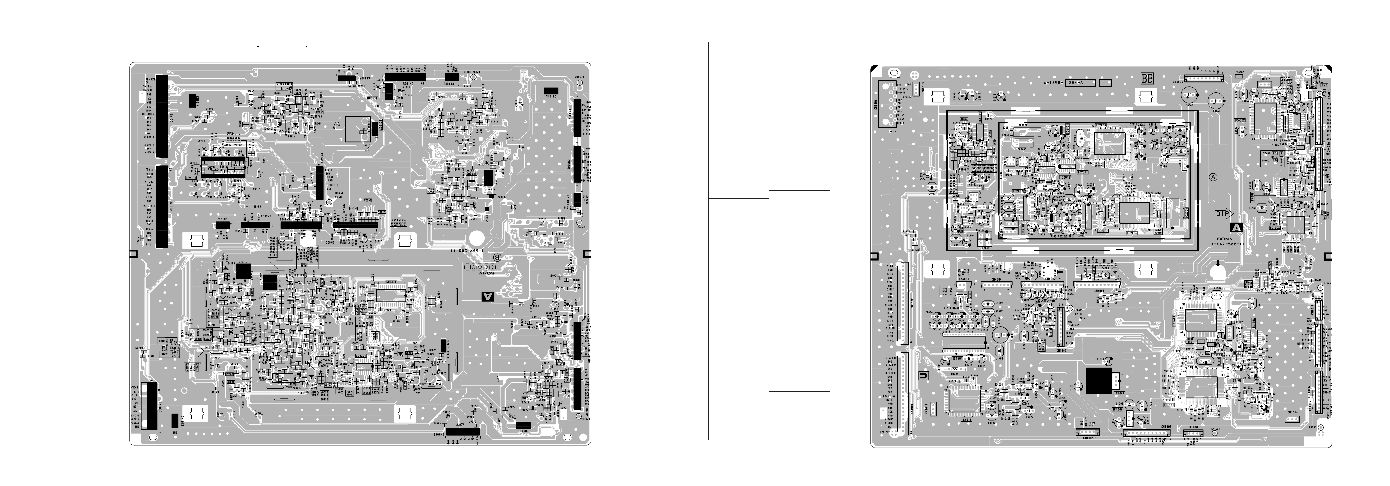
Schematic diagrams
Ò (ha) (hb) (k) (ta) (tb) boards
— A BOARD (Conductor Side) —
(a)
KL-W7000/W9000
RM-Y980
SYSTEM CONTROL,
VIDEO PROCESS
KL-W7000/W9000
RM-Y980
• A BOARD SEMICONDUCTOR LOCATION
IC
Component
Conductor
()
()
Side
IC1007 E–3 E–4
IC1008 E–3 E–4
IC1101 E–5
IC1102 E–5
IC1103 D–5
IC1106 D–5
IC1401 D–5 D–2
IC1601 D–5
IC1602 D–2
IC2001 B–3
IC2003 B–2
IC2004 A–3
IC2006 B–4
IC2007 B–3
IC2008 B–4
IC2009 B–3
IC2011 B–3
IC2012 B–3
IC2101 A–3
IC2102 B–3
IC4001 B–6
IC4002 A–5
IC4003 C–6
IC4004 A–6
IC4008 A–2
IC4009 A–2
IC4011 E–2
Side
Q2041 B–4 1
Q2050 B–4 1
Q2051 B–4 1
Q2052 B–4 1
Q2061 A–5 1
Q2062 A–5 1
Q4001 C–3 1
Q4002 C–3 1
Q4003 C–3 1
Q4004 E–2 2
Q4005 E–5 1
Q4006 E–2 2
Q4007 E–5 1
Q4008 A–1 1
Q4009 A–1 1
Q4010 A–1 1
Q4018 B–1 1
Q4019 B–1 1
Q4020 E–2 2
Q4021 E–4 1
Q4025 B–6 !•
Q4026 E–3 2
Q4027 E–4 1
Q4028 E–4 1
Q4034 B–6 2
Q4041 C–3 2
Q4043 C–3 2
Q4044 A–2 2
Q4045 A–2 2
KL-W7000/W9000
RM-Y980
— A BOARD (Component Side) —
KL-W7000/W9000
RM-Y980
DIODE
Component
TRANSISTOR
Component
Conductor
()
()
Q1101 D–5 !•
Q1102 E–6 2
Q1103 D–5 2
Q1105 E–5 2
Q1108 C–1 2
Q1408 D–3 2
Q1409 D–3 2
Q1410 D–3 2
Q1601 D–2 1
Q1602 D–2 1
Q1603 C–6 2
Q1604 C–6 2
Q1605 C–6 2
Q1606 C–6 2
Q1607 C–6 2
Q1608 C–6 2
Q2001 C–2 2
Q2002 C–3 2
Q2003 B–5 1
Q2004 C–5 1
Q2005 B–2 2
Q2007 B–4 1
Q2008 B–4 1
Q2009 B–4 1
Q2010 B–3 2
Q2011 A–4 1
Q2012 A–4 1
Q2013 A–3 1
Q2014 B–4 1
Q2015 A–4 1
Q2016 B–4 1
Q2017 B–4 1
Q2018 B–5 1
Q2019 B–5 1
Q2020 B–5 1
Q2021 B–5 1
Q2024 B–4 1
Q2027 B–4 1
Q2028 B–5 1
Q2029 B–5 1
Q2030 B–3 1
Q2031 A–3 1
Q2035 B–5 1
Q2036 B–5 1
Q2037 B–5 1
:Refer to Terminal name of semiconductors in silk
*
screen printed circuit (see page 54)
Side
Side
D1011 E–3 3
*
D1025 E–3 3
D1031 D–6 3
D1032 D–6 3
D1102 E–5 3
D1103 E–5 3
D1104 E–2 3
D1105 E–2 3
D1401 D–5 3
D1402 D–5 3
D1405 D–3 3
D1406 D–3 3
D1407 D–2 3
D1408 D–3 3
D1601 C–2 8
D1605 C–6 3
D1606 C–2 3
D2001 B–3 3
D2002 A–4 3
D2004 B–3 3
D2005 A–3 3
D2006 B–4 3
D2008 B–3 3
D2009 B–3 3
D2010 B–3 3
D2011 B–3 3
D4001 C–1 3
D4002 B–6 3
D4005 B–2 3
D4006 B–2 3
D4007 B–2 3
D4008 B–2 3
D4009 B–2 3
D4010 B–2 3
D4011 B–2 3
D4012 B–2 3
X1101 D–2 D–5
X1601 D–2 D–5
X2001 A–4 A–3
X2002 B–4 B–3
X2003 B–4 B–3
– 60 –– 59 –
Conductor
()
()
Side
Side
CRYSTAL
Component
Conductor
()
()
Side
Side
*
– 62 –– 61 –
Page 45

(2) Schematic Diagram of A (1/3) Board
CN1402
8P
RED
:S-MICRO
L OUT
GND
R OUT
GND
L+R OUT
+9V
SP MUTE
HP ON
TO K BOARD
CN8505
(2/3)
+9V
(3/3)
+5V-A
(3/3)
SUB+5V
CN1003
4P
BLK
:S-MICRO
GND
SUB+5V
RXD
TXD
CN1005
10P
RED
:S-MICRO
NC
+17V
+10V
+10V
+10V
GND
GND
GND
GND
POWER CTL
TO G BOARD
CN604
2VP
(3/3)
+17V
(3/3)
(3/3)
+10V
NTSC SW
(3/3)
CN1016
GND
CN1015
GND
CN1014
GND
TO BS SHIELD
CN1013
GND
TO G BOARD
(CN6007)
GND
B-INT2
B-DAT2
B-CLK2
2HV
NC
NC
GND
B-INT
B-DAT
B-CLK
CN1006
11P
BUS CN
8
7
6
5
4
3
2
1
1
2
3
4
1
2
3
4
5
6
7
8
9
10
1
1
1
1
1
2
3
4
5
6
7
8
9
10
11
Q1410
2SB709A
MUTE SW
D1011
MA111
C1001
47
25V
R1005
:CHIP
R1448
220
:CHIP
Q1409
2SD601A
MUTE SW
1
µPC2409AHF
100
R1002
R1003
R1004
R1447
22k
:CHIP
CH:CHIP
123
3
IC1007
+9V REG
R1006
100
:CHIP
100 :CHIP
100 :CHIP
100 :CHIP
D1405
MA111
D1408
MA111
R1446
10k
:CHIP
R1444
4.7k
:CHIP
C1443
220p
R1445
47k
:CHIP
+10V
2
C1004
47
16V
D1105
RD5.6SB-T1
D1104
RD5.6SB-T1
2HV
(3/3)
C1007
0.1
25V
F:CHIP
+9V
R1443
:CHIP
D1406
MA111
C1442
220
16V
100
Q1408
2SB709A
MUTE SW
D1404
#
D1407
MA111
R1442
100
:CHIP
AUDIO(L)
AUDIO(R)
R1413
0
:CHIP
R1414
0 :CHIP
D1401
RD10SB
D1402
RD10SB
C1416
4.7
C1417
10
C1418
0.0047
B:CHIP
R1410
0 :CHIP
R1411
330
:CHIP
R1412
330 :CHIP
C1419
10
SCL
SDA
TA8776N
PROCESS
LOUT
ROUT
16 17 18 19 20 21 22 23 24 25 26 27 28 29 30
LIN
RIN
IC1401
AUDIO
MUTE
+9V
123456789101112131415
C1435
0.033
:PT
C1436
0.1
:PT
C1437
0.033
:PT
C1438
0.033
:PT
C1434
0.001
B:CHIP
#
C1405
#
C1406
#
C1407
#
C1408
C1409
2.2
C1410
2.2
R1405
390k :CHIP
C1411
1
C1412
1
C1413
10
R1404
#
C1414
10
C1415
10
C1440
0.1
25V
F:CHIP
C1401
C1404
C1439
47
25V
47 16V
1000 16V
R1439
330
1W
:RS
R1402
0 :CHIP
R1403
0 :CHIP
+17V
AUDIO(L)
AUDIO(R)
L1401
22µH
C1402
0.1 25V F:CHIP
C1403
0.1 25V F:CHIP
L1402
22µH
R1115
1k
:CHIP
+9V
1
2
2
1
R1200R1201R1202
100
:CHIP
RB1105
100x2 :CHIP
C1113
0.01
B:CHIP
C1110
0.01
VCC
I HD
I SIRCS N
O D-SUB1 SW
I VD
I BINT N
I MPWR N
I RXD
O TXD
I VP MAIN
ADVCC
I KEY0
I KEY1
1 2 3 4 5 6 7 8 9 10 11 12 13 14 15 16 17 18 19 20 21 22 23 24 25 26 27 28 29 30
AVSS
9.8304MHz
C1114 C1117
27p CH:CHIP 27p CH:CHIP
IC1102
PST9143N
RB1106
RB1107
100x2 :CHIP
220x2 :CHIP
C1121
100p
CH:CHIP
VSS
IO IICLK 1
IO IIDAT 1
IO IICLK 2
IO IIDAT 2
I OSC
TEST
O SUBOSC
I SUBOSC
VSS
O OSC
23
R1111
1M :CHIP
X1101
R1112
10k :CHIP
45
VCC
RESET
1 2 3
O MUTE
POW CTL
IC1101
HD6473947-IT-OTP
SYSTEM CONTROL
I RESET N
I NMI N
R1113
10k
:CHIP
C1120
0.01
B:CHIP
RESETGND
I H-POL
O SPMUTE
O NTSC SW
D1025
MA111
C1013
47
25V
IC1008
PQ09RF11
+9V REG
RB1101
220x2 :CHIP
SUB+5V
I V-POL
I H SYNC
I CK
R1122
100
:CHIP
+10V
4
1 2
3
R1011
220
:CHIP
123
FAN +9V
FAN PROT2
C1107
100p
CH:CHIP
R1106
220 :CHIP
C1102
100p CH:CHIP
C1103
100p CH:CHIP
R1102
4.7k
:CHIP
123
BS LED
SUB+5V
STBY LED
POWER LED
100
:CHIP
C1108
470
10V
1
GND
L1101
47µH
B:CHIP
81
82
83
84
85
86
87
88
89
90
91
92
93
94
95
96
97
98
99
100
SUB+5V
100
:CHIP
C1104
R1105
100p CH:CHIP
220 :CHIP
R1104
1k :CHIP
RB1103
220x2 :CHIP
43
21
R1101
4.7k
:CHIP
1
2
123456789
CN1012 CN1008 CN1009
9P
WHT
:S-MICRO
TO HA BOARD
CN8003
KEY 0
KEY 1
GND
SIRCS IN
5
O NO VIDEO
O 3DB DWN
I FILTER COV
I FAN PROT2
I LAMP PROT
O LAMP CTRL
O POWER LED
R1012
1k
:CHIP
C1016
0.1
25V
F:CHIP
C1014
47
25V
C1015
0.1
25V
F:CHIP
GND
3P
WHT
:S-MICRO
TO FAN 2
(LAMP)
R1154
100
:CHIP
515253545556575859606162636465666768697071727374757677787980
O FAN CTRL
I LAMP COV
I TMP PROT
FAN PROT1
O STBY LED
O BS LED
VCC
O WP
I OSD BUSY
O OSD RST
VSS
1
4
+9V
9P
BLK
:S-MICRO
C1126
47
10V
50
49
48
47
46
45
44
43
42
41
40
39
38
37
36
35
34
33
32
31
R1119
C1128
C1129
C1130
C1131
C1132
C1133
C1134
C1135
C1136
C1137
6
R1013
220 :CHIP
123456789
FAN +9V
FAN PROT1
GND
TO FAN1
C1127
0.01
:CHIP
1
220 :CHIP
100p CH:CHIP
100p CH:CHIP
0.1 B:CHIP
100p CH:CHIP
0.1 B:CHIP
100p CH:CHIP
100p CH:CHIP
100p CH:CHIP
100p CH:CHIP
100p CH:CHIP
220 :CHIP
C1017
0.1
25V
F:CHIP
R1015
R1014
220 :CHIP
LAMP COV
GND
FILTER COV
R1168
4.7k
TC74HC4066AF
:CHIP
VCCIC4C
1I/0
10/I
1 2 3 4 5 6 7
R1151
#
R1120
220 :CHIP
GND
GND
POWER ON
TO HB BOARD
CN8031
TO TB BOARD
CN9551
TO TA BOARD
CN9501
TO U BOARD
1
2
IC1106
SW
2
891011121314
4I/0
40/I
30/I
3I/0
20/I
2I/02C3C
GND
RB1113
220x2 :CHIP
RB1110
220x2 :CHIP
RB1111
220x2 :CHIP
43
21
220x2 :CHIP
RB1114
220x2 :CHIP
R1016
220
:CHIP
CN1011
3P
RED
:S-MICRO
RB1112
7
FLAG
CN1001
20P
CN602
GND
SUB +5V
20
R1167
4.7k
:CHIP
1
2
3
8
532
R1018
220
:CHIP
R1017
220 :CHIP
123
SCI
(3/3)
TEMP
TO LAMP DRIVER
(CB-2)
NC
V SYNC
18
19
+5V
1
2
3
4
5
6
7
8
C1018
0.1
25V
F:CHIP
SCL
H SYNC
GND
15
16
17
2
3
C1019
F:CHIP
0.1
25V
SDA
14
1
GND
13
MUTE
12
GND
GND
D SUB1 SW
10
11
R1125
0
:CHIP
R1130
220
:CHIP
C1140
220p
CH:CHIP
C1020
0.1
25V
F:CHIP
GND
GND
Q1101
XN4215
4
2
6
3
R1132
100k
:CHIP
C1141
0.047
B:CHIP
R1133
1M
:CHIP
C1021
0.1
25V
F:CHIP
GND
GND
GND
D SUB B
D SUB G
B(PC)
G(PC)
R(PC)
1
4
1
5
2
6
5
3
H SYNC DET
10k
:CHIP
C1022
0.1
25V
F:CHIP
D1031
RD5.6SB-T1
D SUB R
123456789
1
2
4.7k :CHIP
R1108
10k
:CHIP
Q1102
H SYNC DET
2SB709A
R1140
C1142
4.7k
1
:CHIP
10k
:CHIP
D1032
RD5.6SB-T1
+9V
SUB+5V
R1128
4.7k :CHIP
R1129
5 6 7 8
R1134 R1138
47
:CHIP47:CHIP
TP1101
Q1105
2SB709A
C1145R1139R1135
220p
CH:CHIP
1234
VSS
IC1103
24LC16BT(-TR)
EEPROM
NP
SDA
SCL
R1103
#
C1144
0.01
TP1102
D1102
MA111
D1103
MA111
B:CHIP
R1109
Q1103
2SB709A
RESET SW
R1141
4.7k
:CHIP
V POL
H POL
19
20
R1156
1k
:CHIP
R1157
0
:CHIP
Q1108
2SB709A
Y BUFFER
AUDIO(L)
1
2
+5V
L1102
#
C1146
1
TP1103
47µH
R1107
330
:CHIP
BLM41A01
(1/3)
A
FB1601
BLM41A01
C1601
47
L1601
10V
22µH
FB1602
Q1601
2SB709A
VP BUFFER
C1602
0.01
B:CHIP
R1603
10k
:CHIP
CH:CHIP
R1604
10k
:CHIP
Q1602
2SB709A
HP BUFFER
R1605
1k
:CHIP
VDD
(SYSTEM CONTROL)
GND
GND
GND
L IN
CLP IN
14
15
16
17
18
R
R1610
270
:CHIP
C1603
47
10V
Q1603
2SB709A
OSD R BUFFER
R1611
270
:CHIP
R1608
2.2k
:CHIP
R1609
2.2k
:CHIP
R1606
220
:CHIP
52
53
R1607
54
55
56
57
58
59
60
61
62
63
64
C1605
47p
CH:CHIP
C1604
22p
1k :CHIP
R IN
GND
12
13
R1155
:CHIP
IN
VIDEO
11
100
GND
10
GND
C OUT
+9V
GND
GND
Y OUT
GND
C IN
CN1002
20P
TO U BOARD
Y IN
CN601
123456789
AUDIO(R)
G
R1613
270
:CHIP
R1612
1k
:CHIP
R1614
270
:CHIP
Q1604
2SB709A
OSD G BUFFER
D1601
MA152WK
1
2
RB1602
RB1601
100x2
:CHIP
22p
22p
22p
C1608
C1610
C1609
CH:CHIP
CH:CHIP
IO SDAT
IO SCLK N
GND
SET5V
SET5V
GND
4
I HP
I VP
5
O HALF BLNK2
1 2 3 4 5 6 7 8 9 10 11 12 13 14 15 16 17 18 19
B
R1618
R1616
:CHIP
R1615
1k
:CHIP
R1617
:CHIP
OSD B BUFFER
I
100x2 :CHIP
CH:CHIP
O I
O OSDBLNK
O HALFBLNK
CXP853P40AQ-3-
1k
:CHIP
270
270
Q1605 Q1607
2SB709A
G
B
R
C1614
100p
CH:CHIP
RB1603
RB1604
100x2 :CHIP
100x2 :CHIP
L1602
3.3µH
C1612
C1613
C1611
22p CH:CHIP
22p CH:CHIP
22p CH:CHIP
O B
O G
O R
I DOSC
IC1601
035
OSD
D1606
MA111
5
C1616
100p
CH:CHIP
I CS
O DOSC
R1619
390
:CHIP
R1620
390
:CHIP
R1621
390
:CHIP
R1622
680
:CHIP
Q1606
2SD601A
B SW
R1623
680
:CHIP
2SD601A
G SW
R1624
680
:CHIP
Q1608
2SD601A
R SW
R1625
1k
:CHIP
+5V
R1630
0 :CHIP
33343536373839404142434445464748495051
O BUSY
I RESET N
I OSC
6
O OSC
GND
Y
C
G(PC)
B(PC)
I
C1617
100p
CH:CHIP
R1626
10k
:CHIP
C1618
100p
CH:CHIP
R1627
10k
:CHIP
C1619
100p
CH:CHIP
R1628
10k
:CHIP
D1605
MA111
3
IC1602
S-80743AL-A7
RESET
1 2 3
C1621
B:CHIP
R1629
10k
:CHIP
32
31
30
29
28
27
26
25
24
23
22
21
20
C1620
0.01
B:CHIP
X1601
8.00MHz
B-SS530.<U/C>-A..P1
R(PC)
R1646
1k
:CHIP
0.01
YCV
C
COMB Y
COMB C
CLP≠≠≠≠≠
RGB HD
RGB VD
SDA
(2.3)
SCL
(2.3)
R
(3/3)
G
(3/3)
B
(3/3)
OSD B
OSD G
OSD R
YM
(3/3)
YS
(3/3)
2HP
2VP
(2/3)
(2/3)
(2/3)
(2/3)
(3/3)
(3/3)
(3/3)
(3/3)
(3/3)
(3/3)
(3/3)
(3/3)
(3/3)
(3/3)
(3/3)
• A(1/3) BOARD
IC1602 S-80743AL-A7
2
–
+
3
• A (1/3) BOARD WAVEFORMS
12
4.7 Vp-p (V)
3.9 Vp-p (9.83 MHz)
45
4.4 Vp-p (1/2 H)
• A (1/3) BOARD VOLTAGE LIST
Ref. Pin No. Voltage [V]
IC1008 4 5.0
IC1101 10 2.3
11 2.4
12 5.0
13
19 4.9
20 0
32 0
33 0
35 0.2
36 4.7
37 0.2
38 5.0
39 0.2
40 0.1
41 0.1
42 0
43 0
44 0
46 50
53 0
55 0
61 0
62 0
64 0
65 0
67 4.6
72 4.8
73 4.8
74 5.1
75 5.1
77 4.6
83 5.0
84 4.7
4.5 Vp-p (V) 5.2 Vp-p (8 MHz)
Ref. Pin No. Voltage [V] Ref. Pin No. Voltage [V] Ref. Pin No. Voltage [V]
85 4.7
86 5.0
87 0
89 2.5
90 4.9
*
IC1102 4 5.0
IC1103 5 4.8
IC1401 1 4.4
91 0
93 5.0
94 5.0
6 4.8
7 0.2
2 4.4
3 4.4
4 4.4
5 4.4
6 4.4
7 4.4
8 1.8
9 4.4
10 4.3
11 4.4
13 2.9
14 2.6
15 12.2
18 4.4
19 5.0
20 4.9
22 5.1
25 1.4
26 6.0
27 2.1
3
4.4 Vp-p (H)
6
IC1601 1 0
IC1602 1 5.2
Q1101 B1 5.2
Q1102 B 5.2
Q1105 B 0
28 5.0
29 5.0
28 2.6
29 2.2
30 5.2
32 0
37 5.1
39 2.7
40 2.7
41 0
42 0
43 0
44 0
45 0
46 0
48 5.2
50 5.2
59 0.9
60 0.8
2 5.2
C1 4.9
E1 4.8
B2 5.2
C2 5.0
E2 4.8
C 0.9
1
E 0.7
Q1408 B 9.2
Q1409 B 0
Q1410 B 9.0
Q1601 B 0
Q1602 B 0.2
Q1603 B 0
Q1604 B 0
Q1605 B 0
Q1606 B 0
Q1607 B 0
Q1608 B 0
C –0.5
C 9.0
C –1.1
E 0.8
E 0.9
E 0.7
E 0.7
E 0.7
C 0.7
C 0.7
C 0.7
– 64 –– 63 –
– 65 –
– 66 –
Page 46

(3) Schematic Diagram of A (2/3) Board
• A(2/3) BOARD
IC2001 µPC659AGS
7 8 1 10 5
Schematic diagram
Ò (a)(1/3) board
(1/3)
YCV
Y
R2001
22k
:CHIP
Q2001
2SD601A
1k
LIMITER
5.6k
R2019
10
100k
:CHIP
Q2007
BUFFER
R2031
1k
:CHIP
SS1
CS0
VSS1
2
HDF
H00
HK0
SGND
HSOF1
HSOF2
3
HSOF3
ASCF
SVCC
HS0
NHS0
4
CP0
F10
VSO
192021222324252627282930313233343536
5
N/P
IC2003
µPC1862GS
H/V SYNC,
CLP PROCESS
1 2 3 4 5 6 7 8 9 10 11 12 13 14
D0
D1
D2
D3
IC2011
LA7217M
SYNC SEPARATE
C2106
0.022
B:CHIP
R2191
470
:CHIP
R2195
15k
:CHIP
R2198
10k
:CHIP
R2004
15k
:CHIP
Y
R2015
3.3k
:CHIP
R2144
0
:CHIP
Q2008
R2027
2SB709A
1k
:CHIP
BUFFER
R2039
C2038
2.7k
:CHIP
CH:CHIP
R2042
270 :CHIP
C2046
R2141
100
:CHIP
C2051
C2052
47
10V
B:CHIP
IC2009
MSM514222B
MEMORY
NC
NC
WE
RSTW
RSTR
SWCK
0
Din
SRCK
NC
NC
Dout
1
Din
Dout
2
Din
Dout
3
Din
Dout
NC
NC NC
VSS
R2197
10k
:CHIP
R2029
:CHIP
C2028
0.001
B:CHIP
220p
4.7
0.01
VCC
NC
NC
RE
NC
NC
0
1
2
3
NC
R2011
100
:CHIP
47k
R2040
2.2k
:CHIP
C2069
0.1
25V
B:CHIP
+5V
1516171819202122232425262728
:CHIP
C2022
1
R2032
220
:CHIP
C2112
0.001
B:CHIP
C2039
0.0015
CH:CHIP
X2002
503KHz
R2044
8.2k :CHIP
R2045
1.5k
:CHIP
Q2009
2SD601A
AFC SW
R2061
:CHIP
C2007
10
FL2001
TYV-288
46
L2001
8.2µH
R2003
:CHIP
Q2005
2SB709A
Y BUFFER
R2016
:RN-CP
R2018
:CHIP
2SD601A
R2006 R2005
47
:CHIP
C2006
22
25V
R2013
12k
:CHIP
R2002
:CHIP
1
Q2003
2SD601A
YCV BUFFER
R2010
:RN-CP
R2017
:RN-CP
10
560
CH:CHIP
470
C2012
10
R2014
300
:RN-CP
C2009
15p
C2001 C2002
0.01
B:CHIP4716V
1 2 3
C2013
0.01
B:CHIP
+5V
C2034
B:CHIP
C2058C2062
0.01
B:CHIP
B0
B1
B2
B3
B4
B5
B6
B7
R2185
24k
:RN-CP
X2003
CSB500F9
VCC
AFC
R2135
150k
:CHIP
R2192
470
:CHIP
0.01
C2079
0.01
B:CHIP
R2082
:CHIP
C2124
1000p
CH:CHIP
891011121314
C2122
0.001
B:CHIP
R2182
10k
:CHIP
VCO0
VCO1
SYNCVDGND
R2193
1k
:CHIP
Q2061
2SD601A
VD AMP
C2190
0.01
B:CHIP
R2196
15k
:CHIP
1 2 3 4 5 6 7 8 9 10 11 12 13 14 15 16 17 18
SCO
CVCC1
TINT
CIN
ACCF
CKO
CKF
COUT
APCF
CGND
SCOF1
SCOF2
SCOF3
CVCC2
CVCC3
CVOO
DIVS
ESC1
0
C2087
820p
B:CHIP
9
891011121314
HD
DET
EXC
R2081
C2078
0.1 25V B:CHIP
+5V
R2175
100k :CHIP
D2006
MA111
R2173
:RN-CP
R2174
68k
:RN-CP
1000p CH:CHIP
C2126
47
16V
(3/3)
L2006
1.2µH
L2007
1.2µH
A0
A1
A2
A3
A4
A5
A6
0 :CHIP
A7
B:CHIP
R2176
D2008
33k :RN-CP
Q2051
2SB709A AMP
R2178
4.7k :CHIP
12k
C2120
IO
G
C2127
IC2101
0.1
µPC78L05T
25V
+5V REG
F:CHIP
+9V
(3/3)
NTSC HD
L2002
1.2µH
C2116
0.01
B:CHIP
IC2008
µPD42280GU
MEMORY
1 2 3 4 5 6 7 8 9 10 11 12 13 14
DI1
DI2
DI3
WE
GND
TEST
WRST
WCK
VDD
DI4
DI5
DI6
DI7
R2183
270k
:RN-CP
C2125
0.01
R2184
10k
:RN-CP
MA111
D2009
MA111
R2181
82k
:RN-CP
R2179
10k
:CHIP
Q2052
2SB709A BUFFER
:RN-CP
Q2050
2SD601A
BUFFER
R2177
10k
:RN-CP
C2096
47
10V
+5V
C2104
0.0022
B:CHIP
NTSC VD
C2036
0.01
B:CHIP
C2037
0.01
B:CHIP
C2040
0.01
B:CHIP
C2043
0.01
B:CHIP
C2057
0.01
B:CHIP
0.01
B:CHIP
DO0DI0
DO1
DO2
DO3
RE
GND
OE
RRST
RCK
VDD
DO4
DO5
DO6
1516171819202122232425262728
DO7
D2011
MA111
C2123
0.1
16V
:PPS-CP
IC2012
TC74VHC04F
INV
1 2 3 4 5 6 7
R2180
D2010
150k
MA111
C2121
0.1
16V
:PPS-CP
C2085
C2086
0.01
1
B:CHIP
R2099
2.2k
:CHIP
C2097
0.1
R2103
25V
560
F:CHIP
:CHIP
NC
NCYF.B
1 2 3 4 5 6 7
C2107
1
C2108
0.056
25V
B:CHIP
R2194
1k
:CHIP
Q2062
2SD601A
HD AMP
1.8k
2SD601A
Y BUFFER
Q2004
2SB709A
Y BUFFER
R2021
R2022
390
:CHIP
:CHIP
R2024
22k
C2023
1
R2033
220
:CHIP
0.01
100k
Q2010
2SD601A
INV
B5
B4
B3
B2
B1
B0
R2069
82 :CHIP
R2072
82 :CHIP
D3
D2
D1
D0
R2077
0 :CHIP
E0
E1
E2
E3
+5V-A
(3/3)
E3
E2
E1
E0
:RN-CP
R2046
10k
:CHIP
C2076
0.1
25V
B:CHIP
L2009
18µH
L2010
8.2µH
C2093
0.01
B:CHIP
C2101
47
16V
R2030
47k
:CHIP
C2035
B:CHIP
R2037
:CHIP
C2045
0.01
B:CHIP
0
R2083
0
:CHIP
C2080
0.1
25V
B:CHIP
Schematic diagram
(a)(1/3) board l
+9V
Q2002
+5V
C2010
10
390
C2015
0.1
R2025
C2014
100
10V
R2047
10k
:CHIP
31
DVDD
32
9
33
8
34
7
35
6
36
5
37
4
38
MRSB
39
MRS
40
MWCK
41
MRCK
42
3
43
2
44
1
45
0
46
3
47
2
48
1
49
0
50
DVDD
R2035
:RN-CP
25V
10k
B:CHIP
:RN-CP
C2017
0.1
25V
B:CHIP
Y
D2001
MA111
C2024
0.1
25V
B:CHIP
3.9k
B:CHIP
B6
DGND
FMI10
OUT
IN
MD0
DGND
515253545556575859606162636465666768697071727374757677787980
C2026
B:CHIP
C2031
0.1
25V
C2033
0.1
25V
B:CHIP
C2042
47
10V
A0A1A2A3A4A5A6
B7
4
FMI11
MD1
MD2
MD3
SCL
0.1
25V
SDA
TES1(RST)
IC2001
µPC659AGS
A/D CONVERTER
1 2 3 4 5 6 7
VRT
NC
AVCC
VIN
AGND
PCL
VCL
8
AVCC
AGND
109 11 12
VRB
AVCC
AGND
C2130
0.1
25V
F:CHIP
Y0Y1Y2Y3Y4Y5Y6
A7
0
98765
11
10
3D/COMB FILTER
DC0
DC1
DC2
DC3
CLK
OVER
DB1
DB2
6
DB3
DGND
DVCC
DB4
DB5
DB6
DB7
131415161718192021222324
DB8
IO
G
IC2102
µPC78L05T
+5V REG
0H
IC2006
µPD6487GF
DC DY
DC4
DC5
DC6
DC7
C2129
0.1
25V
F:CHIP
Y7
DC8
DY0
R2026
:CHIP
0.1 25V B:CHIP
C2128
47
16V
7654321
ADCK
CLPO/C
DY1
DY2
82
L2004
1.2µH
0
DY3
C2021
DY4
+5V
C2084
C2083
0.01
47
10V
L2011
C2102
0.01
B:CHIP
18µH
B:CHIP
C2103
0.01
B:CHIP
C2117
0.01
B:CHIP
FL2015
TU01M
EMI
C2090
47
10V
C2091
0.01
B:CHIP
+9V
+9V
(1/3)
DY5
C2025
47
10V
DY6
Y7
Y6
Y5
Y4
Y3
Y2
Y1
Y0
DY7
876543210876543210TES2
DY8
(1/3)
(1/3)
(1/3)
COMB CCCOMB Y
CLAMP
4
S/H
+
–
SAMPLE-HOLD
C
+5V
5
FLASH
A/D CONVERTER
5
D/A
FLASH
A/D CONVERTER
5
5V
Q2030
2SD601A
+3.3V REG
R2157
R2158
330
330
:CHIP
:CHIP
C2019
47
Y
10V
C2020
0.01 B:CHIP
C2118
10
R2159
100k :CHIP
D2004
DTZ3.9B
C2029
47 10V
C2030
0.01 B:CHIP
+5V
Y
C2059
47 10V
Y7
Y6
Y5
Y4
Y3
Y2
C2060
0.01
B:CHIP
+5V
+9V
C2049
47 10V
C2050
B:CHIP
R2160
330
:CHIP
0.01
Q2031
2SD601A
+3.3V REG
R2161
330
:CHIP
R2162
100k
:CHIP
C2119
10
D2005
DTZ3.9B
+5V
R2048
1k
R2053
:CHIP
560
:CHIP
1 6
18
1 2 3 4 5 6 7 8 9 10 11 12 13 14 15 16 17 18 19 20 21 22 23 24 25 26 27 28 29 30
VTR
7654321
7
8
CTL
DGND
BVCO
DVDD
KIL
CLPI
VDI
AGND
IOY
AVDD
COMP
VREF
IREF
AVDD
IOC
AGND
HSS
REF
DGND
HPD
DVDD
HVCO
DGND
C2099
B:CHIP
100
99
98
97
96
180 :CHIP
95
94
93
92
91
90
1.5k :CHIP
89
88
87
86
85
84
83
82
81
B:CHIP
FL2019
TX14271NB
EMI EMI
EMI EMI
FL2021
TX14271NB
0.1
25V
R2212
R2215
R2216
180
:CHIP
C2075
100p
CH:CHIP
C2077
0.1
25V
FL2022
TX14271NB
R2064
47k
:CHIP
R2213
4.7k
:CHIP
R2214
39k
:CHIP
C2072
0.1
25V
B:CHIP
R2078
0
:CHIP
FL2020
TX14271NB
SCL
(1/3)
C2070
0.1
25V
B:CHIP
C2071
0.1
25V
B:CHIP
C2098
0.1
25V
B:CHIP
L2008
1.2µH
C2073
47
10V
5V-2
Y
Y
SDA
(1/3)
(3/3)
5V
2SB709A
R-Y BUFFER
1k
:CHIP
R-Y
B-Y
R-Y
B-Y
(3/3)
(3/3)
SDA
SCL
2SB709A
Y BUFFER
R2201
270
:CHIP
R1203
1k
:CHIP
1k
:CHIP
R1204
820
:CHIP
C
Q2041
2SD601A
Y BUFFER
R2171
180
:CHIP
Q2035Q2036Q2037
2SB709A
B-Y BUFFER
R2203R2204R2205
1k
:CHIP
R2202
1.2k :CHIP
R1205
:CHIP
R2056
220
:CHIP
R2151
1k
:CHIP
Q2028
2SB709A
C BUFFER
R2150
100
:CHIP
R2211
4.7k
:CHIP
C2140
47p
CH:CHIP
R2172
680
:CHIP
R2200
270
:CHIP
1k
Q2012
2SB709A
YS BUFFER
R2152
560
:CHIP
C2115
15p
CH:CHIP
R2090
560
:CHIP
1 6
R2111
560
:CHIP
R2129
560
:CHIP
FL2002
TCV-3227
Y
FL2004
TCV-3227
R-Y
B-Y
DC7
DC8
DY0
DY1
DY2
DY3
DY4
DY5
DY6
DY7
DY8
3.3V-2
811
1 2 3
FL2007
TYV-288
811
1 2 3
FL2005
TYV-287
1 2 3
FL2006
TYV-287
C2003
0.1
25V
B:CHIP
81
82
83
84
85
86
87
88
89
90
91
92
93
94
95
96
97
98
99
100
R2153
1.5k
:CHIP
46
+5V
R2112
0
:CHIP
46
R2130
:CHIP
46
R2007
3.3k
:CHIP
R2008
2.2k
:CHIP
VBC
AVSD
IRFC
VRFC
IC2004
CXD2052Q
CHROMA DEC
AVDC
AVSC
C2055
0.1
25V
B:CHIP
R2052
2.2k
:CHIP
C2068
0.1
25V
B:CHIP
C2004
0.1
25V
B:CHIP
R2012
3.3k
:CHIP
NC
RYONCBYO
VGC
AVDR
AVSR
AVS
ADIN
C2048
0.1
25V
B:CHIP
R2050
:CHIP
R2057
:CHIP
LEVEL SHIFT
2.2k
1k
Q2013
2SB709A
C
B:CHIP
BK2125HM601
AVD
C2065
0.01
FB2002
AVSB
RT
TST0
DC6
DC5
DC4
+3.3V
DC3
DC2
DC1
DC0
C2008
0.1
25V
B:CHIP
C2005
0.1
25V
B:CHIP
Y
NC
DYO
EXC7
EXC6
VDD3
EXC5
EXC4
EXC8
EXC9
EXY0
EXY1
EXY2
EXY3
EXY4
EXY5
EXY6
VSS3
EXY7
EXY8
EXY9
EDTV
VIN8
VIN7
VIN6
VIN5
VIN4
VIN3
VIN2
1 2 3 4 5 6 7 8 9 10 11 12 13 14 15 16 17 18 19 20 21 22 23 24 25 26 27 28 29 30
Y0
Y1
Q2011
2SB709A
YS BUFFER
EXC3
10 11
YSNCVG
VIN1
VIN0
AVSY
AVDY
C2053
0.1
25V
B:CHIP
3.3V
R2049
2.7k
:CHIP
19
R2062
5.6k
:CHIP
AVDD
EXC2
EXC1
EXC0
17 16 15 14 13
VBNCCSNCNCGRRB
VRF
IRF
C2044
0.1
25V
B:CHIP
R2043
3.6k
:CHIP
C2054
0.1
25V
B:CHIP
+5V
R2051
100
:CHIP
R2055
1.2k
R2054
:CHIP
2.7k
:CHIP
C2067
0.1
25V
B:CHIP
C
C2110
R2094
:CHIP
R2113
5.6k
:CHIP
0
R2131
5.6k
:CHIP
R2154
3.9k
:CHIP
5.6k
R2100
820
:CHIP
R2088
:CHIP
0.01
B:CHIP
R2155
1k
:CHIP
Q2029
2SB709A
C BUFFER
820
R2089
0
:CHIP
Y
Q2019
2SB709A
Y BUFFER
26
Q2024
2SB709A
R-Y BUFFER
R2125
820
:CHIP
B-Y
C2109
47
10V
Q2014
2SB709A
CS BUFFER
B-Y
R-Y
Y
Q2021
2SD601A
Y BUFFER
R2108 R2145
470
:RN-CP68:RN-CP
R-Y
27
B-Y
Q2027
2SB709A
B-Y BUFFER
R2132 R2133
0
:CHIP0:CHIP
R-Y
R2073
220
:CHIP
R2109
:CHIP
20
220
R2096 R2097
1k
:RN-CP
R2101 C2088 R2102
10k
:CHIP1k:CHIP
Y
R2065
1k :CHIP
R2071
560
:CHIP
1 6
TCV-2219
33k
:CHIP
Q2020
2SD601A
Y BUFFER
25
10
+5V
FL2003
C2081
0.01
B:CHIP
CS BUFFER
7
C2082
10
Y
NCFVFH
AVDB
SDA
VDD0
SCL
C2047
0.1
25V
B:CHIP
R2059 R2060
0
:CHIP0:CHIP
SDA
SCL
R2066
2.7k
:CHIP
Q2015
2SB709A
R2074
5.6k
:CHIP
+9V
515253545556575859606162636465666768697071727374757677787980
CLP
TST3
TST2
TST1
VSS
VDD
VDD
FSC8
FSC
FSC4
FS4I
VSS1
AVDO
12
AVSO
AVDM
VRTM
ADJ
CON
VSS
AVSM
VRBM
C2063
0.1
25V
B:CHIP
Q2016
2SB709A
B-Y BUFFER
50
49
48
NC
47
46
45
NC
44
43
42
41
40
39
38
37
XO
36
XI
35
34
33
32
31
+3.3V
5V
C2064
47
10V
21
R2068
100
:CHIP
R2076
22
1k
:CHIP
Q2017
2SB709A
R-Y BUFFER
C2011
B:CHIP
C2018
B:CHIP
+3.3V
C2066
0.01
B:CHIP
23
0.1
25V
0.1
25V
:RN-CP
R-Y
R2034
100k
C2032 X2001
680p
28.6MHz
CH:CHIP
D2002
R2038
HVU359
56k
:RN-CP
C2041
330p
50V
CH:CHIP
+5V
FB2037
BK2125HM601
IC2007
MC74F08M
CLOCK BUFFER
1 2 3 4 5 6 7
R2080
1k
:CHIP
B-Y
24
Q2018
2SB709A
Y BUFFER
B-Y
R2036
1k :RN-CP
L2003
0.82µH
:CHIP
891011121314
R2087
1k
:CHIP
R-Y
C2027
10p
CH:CHIP
R2079
200
:RN-CP
R2084
200
:RN-CP
Y
R2091
:RN-CP
200
B-Y
R-Y
TIMING
24
GENERATOR
• A (2/3) BOARD WAVEFORMS
1
2.3 Vp-p (H)
8
Y
4.4 Vp-p (H)
2
1.2 Vp-p (H) 0.7 Vp-p (503 kHz)
9
0.7 Vp-p (500 kHz) 0.9 Vp-p (H)
!∞ !§
1.2 Vp-p (H)
1.0 Vp-p (H) 1.7 Vp-p (H)
@™ @£
(2/3)
A
(VIDEO PROCESS)
B-SS530.<U/C>-A..P2
1.2 Vp-p (H)
• A (2/3) BOARD VOLTAGE LIST
Ref. Pin No. Voltage [V]
IC2001 1 3.5
IC2003 3 2.8
IC2004 1 2.1
1.0 Vp-p (H) 1.7 Vp-p (H)
4 2.9
6 0.4
7 2.8
10 2.5
13 2.0
14 2.1
15 2.3
16 2.5
17 3.0
20 2.3
21 1.8
22 1.6
24 2.3
4 3.4
50
7 3.7
9 2.8
18 3.9
20 4.5
22 0.4
23 4.3
26 3.5
27 3.0
28 4.1
29 4.1
33 4.4
34 3.2
36 3.2
2 2.0
5 0.5
8 1.7
9 1.2
10 1.2
11 0.6
14 0.6
19 1.9
21 2.7
25 5.4
27 5.4
31 2.5
36 1.9
37 2.1
40 2.0
41 1.7
56 5.4
57 1.2
61 1.1
64 3.0
65 2.2
66 2.2
67 0.6
69 0.9
73 2.7
74 2.6
75 2.5
76 2.5
77 2.6
78 3.6
79 2.6
80 2.6
81 2.5
82 2.9
84 2.7
85 2.7
86 2.6
87 3.0
88 2.4
89 3.0
91 2.7
92 2.3
93 1.8
95 1.6
ADDER
5
3
!º
!¶
@¢
Ref. Pin No. Voltage [V]
96 1.8
97 2.3
98 3.0
99 2.5
100 2.3
IC2006 10 2.3
IC2007 1 1.7
IC2008 1 2.9
11 2.6
12 1.6
13 1.8
14 2.3
15 3.0
16 2.5
17 2.3
18 2.1
19 2.0
20 1.8
21 2.1
22 2.8
23 3.5
24 2.7
25 2.7
26 2.7
27 2.9
28 1.5
29 1.6
32 2.7
33 3.3
34 2.5
35 2.4
36 2.3
37 2.8
38 5.4
39 0
40 1.3
41 1.3
42 3.0
43 2.8
44 2.6
45 2.6
46 3.5
47 3.3
48 2.9
49 2.7
56 5.4
57 5.4
60 2.6
61 2.5
62 2.5
63 2.5
64 2.5
65 2.5
66 2.5
67 2.5
68 2.8
69 2.6
70 2.6
71 2.6
72 3.0
73 2.4
74 3.0
75 2.7
76 2.4
77 1.8
78 0
86 4.3
96 4.5
79 0.4
98 0
99 5.4
100 2.0
3 2.0
2 2.7
LATCH
Ref. Pin No. Voltage [V] Ref. Pin No. Voltage [V]
IC2009 3 5.4
IC2011 2 2.6
IC2012 1 1.9
Q2002 B 2.6
Q2003 B 3.3
Q2004 B 1.9
Q2005 B 1.2
Q2007 B 2.3
Q2008 B 1.6
Q2009 B 0.8
Q2010 B 0
3
1314151617202122231918
4
5
4.4 Vp-p (H)
!¡
0.8 Vp-p (H)
!™
0.8 Vp-p (28.6 MHz)
!• !ª
0.8 Vp-p (H)
@∞ @§
1.5 Vp-p (H)
3 2.7
4 2.7
8 5.4
9 1.3
11 3.5
12 2.8
13 2.1
14 1.8
15 1.5
16 1.6
17 2.7
18 3.3
20 1.3
21 5.4
25 2.5
26 2.4
27 2.3
28 2.8
40
5 1.3
6 2.6
9 2.6
10 2.8
11 3.0
17 3.5
18 3.3
19 2.9
20 2.7
23 1.3
24 0
3 3.5
4 4.2
7 5.2
9 4.4
10 4.3
11 3.0
12 2.4
2 4.0
3 4.0
4 4.1
5 4.2
6 0.2
8 4.8
9 0.3
10 0.3
11 4.8
12 4.8
13 0.3
E 1.9
E 2.6
E 2.6
E 1.9
E 1.6
E 2.3
C0
C 0.8
Q2011 B 1.1
Q2012 B 0.5
Q2013 B 1.2
Q2014 B 0.6
Q2015 B 1.2
Q2016 B 1.2
Q2017 B 1.2
Q2018 B 0.9
Q2019 B 1.4
Q2020 B 4.4
Q2021 B 2.2
Q2024 B 1.7
Q2027 B 1.7
Q2028 B 2.8
Q2029 B 2.3
Q2030 B 4.3
Q2031 B 4.3
Q2035 B 1.7
Q2036 B 1.2
Q2037 B 1.6
Q2041 B 2.1
Q2050 B 3.2
Q2051 B 4.4
Q2052 B 5.0
Q2061 B 0.7
Q2062 B 0.5
6
7
4.4 Vp-p (V) 0.9 Vp-p (H) 4.4 Vp-p (V)
!£
!¢
4.5 Vp-p (H) 4.5 Vp-p (V)
@º
@¡
0.8 Vp-p (H) 0.8 Vp-p (H) 0.7 Vp-p (H)
@¶
0.8 Vp-p (H) 0.8 Vp-p (H)
E 1.8
E 1.2
E 1.9
E 1.3
E 1.9
E 1.8
E 1.8
E 1.6
E 2.2
E 3.7
C 4.4
E 1.5
E 2.4
E 2.4
E 3.5
E 3.0
C 5.4
E 3.6
C 5.4
E 3.6
E 2.3
E 1.9
E 2.3
E 1.5
C 4.4
E 2.7
C 5.0
E 1.9
C 0.4
C 0.4
– 67 –
– 68 –
– 69 –
– 70 –
Page 47

(4) Schematic Diagram of A (3/3) Board
CN4004
7P
SCL
SDA
A GND
HD
A GND
VD
A GND
TO BB BOARD
CN3001
CN4007
3P
A GND
CLP
NT SW
TO BB BOARD
CN3004
OUT
Z1
7
Z2
6
5
4
3
2
1
3
2
1
(1/3)
CLP≠≠≠≠≠
NTSC SW
(1/3)
(1/3)
(2/3)
(1/3)
(2/3)
(1/3)
R4353
1k
:CHIP
R4373
0
:CHIP
R4035
0
:CHIP
C4039
0.001
:CH
RGB HD
NTSC HD
RGB VD
NTSC VD
SUB+5V
L4011
10µH
C4100
0.1
25V
Q4044
2SB709A
HD BUFFER
R4330
18k
:CHIP
R4333
10k
:CHIP
R4331
18k
:CHIP
Y
R-Y
L4004
10µH
C4099
100 16V
R4334
10k
:CHIP
R4332
18k
:CHIP
IC4008
TC7S08F
DPH
45
1 2 3
C4032
C4031
0.1
47
25V
16V
B:CHIP
Y
X
VDD
Y1
1 2 3 4 5 6 7 8
Q4004
2SD601A
Y BUFFER
C4201
10
Y0
R4303
0
:CHIP
MC14053BF
SYNC SELECT
Z1
R4354
1k
:CHIP
2SB709A
VD BUFFER
Y
R4302
1k
:CHIP
+5V
Q4006
2SD601A
R-Y BUFFER
R4335
10k
:CHIP
C4211
10
B-Y BUFFER
C4221
10
2SD601A
R4313
0
:CHIP
Q4020
R4323
0
:CHIP
R4312
1k
:CHIP
R4322
1k
:CHIP
R-Y
B-Y
D4005
HVU359
D4006
HVU359
X1
IC4009
Z
Q4045
Q4005
2SD601A
Y AMP
Q4007
2SD601A
R-Y AMP
Q4021
2SD601A
B-Y AMP
HVU359
X0
Z0
R4306
0
:CHIP
R4307
470
:CHIP
R4316
0
:CHIP
R4317
470
:CHIP
R4326
0
:CHIP
R4327
470
:CHIP
D4007
A
INH
R4301
470
:CHIP
R4309
10k
:CHIP
R4311
470
:CHIP
R4318
10k
:CHIP
R4319
10k
:CHIP
R4321
470
:CHIP
R4328
10k
:CHIP
R4329
10k
:CHIP
C4230
0.1
25V
B:CHIP
D4009
HVU359
D4008
HVU359
R4076
+5V
910111213141516
B
C
VEE
VSS
+5V
R4308
10k
:CHIP
Q4026
2SD601A
Y BUFFER
C4202
10
R4304
R4342
82
:CHIP
:CHIP
Q4027
2SD601A
R-Y BUFFER
C4212
10
R4314
R4352
470
150
:CHIP
:CHIP
+5V
Q4028
2SD601A
B-Y BUFFER
C4222
10
R4324
R4362
150
:CHIP
:CHIP
D4011
HVU359
D4010
HVU359
HVU359
R4077
R4078
#
#
C4083
#
1
4
4
1
5
6
R4075
#
6
5
3
#
Q4030
XN4601
SSCP CONTROL
R4340
10k
:CHIP
Y
R4341
10k
:CHIP
470
R4350
10k
:CHIP
R-Y
R4351
10k
:CHIP
R4360
10k
:CHIP
B-Y
R4361
10k
:CHIP
470
D4012
JR4001
0
:CHIP
Q4032
XN4601
SSCP CONTROL
R4079
#
3
3
2
2
C4084
1
4
#
R4080
2
2
3
C4204
0.01
B:CHIP
C4203
47
16V
C4213
47
16V
C4223
47
16V
R-Y
Y
10
Y
D GND
5
6
1
4
#
C4205
R4305
:CHIP
R4315
:CHIP
R4325
0
:CHIP
B-Y
U(R-Y)
5
6
R4081
10k
:CHIP
L4008
22µH
100
16V
0
0
D GND
V(B-Y)
(1)
C4082
5V
680k
:CHIP
#
C4225
100
16V
L4009
22µH
5V
D GND
C4231
0.1
25V
B:CHIP
L4001
18µH
C4018
100
16V
C4224
0.01
B:CHIP
Y
R-Y
B-Y
123456789
CN4002
3.3V
D GND
TO BB BOARD
CN3002
10P
C4232 R4369R4370
47µ
16V
B:CHIP
+9V
C4019
0.01
+9V
100
:CHIP
L4002
10µH
R4089
100 :CHIP
R4090
C4056
0.01
C4055
B:CHIP
10
C4009
10
C4010
1
1k :CHIP
R4042
C4022
0.01 B:CHIP
0.01 B:CHIP
C4028
0.01
B:CHIP
20
21
22
23
24
25
100 :CHIP
26
27
28
29
7
30
31
32
9
+5V
R4002
C4002
10k
22p
:RN-CP
CH:CHIP
GND
GND
C1/R1
1 2 3 4 5 6 7 8
C4051
68p
CH:CHIP
R4013
10k
:RN-CP
23
24
CLP1
P-MUTE
A PED-C
252627282930313233343536
CLP-C
VM-OUT
SP-MUTE
VM-MUTE
YUV-SW
9V-1
GND-1
SUB
C4025
BY1-IN
RY1-IN
Y1-IN
23 45
NC
R-Y2
B-Y2
3738394041424344454647
1
NC
TEST OUT
P ABL FILTER
ABL FILTER
ABL IN
B IN
G IN
R IN
D GND
SDA
SCL
ADDRESS
Y-OUT
8
R-Y OUT
B-Y OUT
IN 0 GND
SW GND
33 34 35 36 37 38 39 40 41 42 43 44 45 46 47 48 49 50 51
C4035
0.33
16V
B:CHIP
C4036
0.33
101112 13
16V
B:CHIP
SW1(CS/YG)
SW2(WY/SW1)
SW3(COLOFF)
SW0(P&P/PIP)
BB VIDEO SELECT
IN 1 GND
Y IN 0
R-Y IN 0
B-Y IN 0
C4037
0.33
16V
B:CHIP
Y
B-Y
R-Y
Y
B-Y
R-Y
(2/3)
(2/3)
(2/3)
V BLK
PR IN 1
A2
RS2
IC4001
C2/R2
MC14528BF
F.F.
RS1A1B1
R4023
100
:CHIP
17
18
19
20
21
22
VS
VEQ
BGP
RGB DEC,OSD MIX
Y2 IN
R4050
27k
:CHIP
SSCP
PB IN 1
C BLK
FF TIM.
IC4003
CXA1839Q
NC
I-REF
C-OFF
DA-TEST
B S/H
AKB GND
H PULSE
IC4011
CXA2011Q
PR IN 2
IN 2 GND
Y IN 1
V BLK
R-OUT
2R2G2B
M4M5M6
B OUT
PB IN 2
B2
Q2
Q1
Q1
Q4035
2SD601A
Z1
Z2
14
15
16
SCL
SSCP
V-TIM
TEXT
OSD
G-OUT
B-OUT
ABL
0.01 B:CHIP
6
R OUT
R S/H
G OUT
G S/H
14 15
HD G IN
HD B IN
HD Y IN 2
IN 3 GND
B(PC)
R4140
1k
:CHIP
910111213141516
Q2
R4143
:CHIP
D4001
MA111
D4002
MA111
R4018
R4144
2.2k
:CHIP
R4024
100
:CHIP
13
SDA
YS2
YS1
LB1-IN
LG1-IN
LR1-N
GND-2
9V-2
YM2
YS2
LB2-IN
LG2-IN
1 2 3 4 5 6 7 8 9 10 11 12
LR2-IN
ABL MUTE
2Y
48
C4049
C4050
0.01
B:CHIP
12345678910111213141516171819
IK IN
I REF
AKB 9V
SS GND
HS IN
VS IN
VS FILTER
VIDEO HS OUT
VIDEO VS OUT
VS OUT
HS OUT
EXT VS IN
EXT HS IN
EXT CS IN
HD SYNC IN
SYNC OUT
SS9V
SW 9V
HD R IN
C4096
0.01
B:CHIP
G(PC)
R(PC)
C4046
0.33 16V B:CHIP
R4142
1k
:CHIP
0
R4019
270
:CHIP
C4048
0.01
B:CHIP
64
63
62
61
60
59
58
57
56
55
54
53
52
#
C4097
R4063
100 :CHIP
C4015
0.01 B:CHIP
2Y
2R-Y
2B-Y
+9V
L4006
22µH
100
16V
C4045 C4044
B:CHIP
0.33 16V B:CHIP0.33 16V B:CHIP
C4098
0.01
Q4034
2SB709A
SSCP BUFFER
R4044
N5
R4046
N4
C4026
N3
C4029
N2
C4030
N1
2V
(1/3)
(1/3)
(1/3)
(1/3)
YS
OSD G
OSD R
OSD B
N1N2N3N4N5
R4020
4.7k
:CHIP
100 :CHIP
100 :CHIP
0.01 B:CHIP
0.01 B:CHIP
0.01 B:CHIP
2U
R
B
G
(1/3)
(1/3)
(1/3)
(1/3)
YM
(1/3)
(1/3)
SCL
SDA
R4091 R4094
470
:CHIP
Q4041
2SD601A-QRS-TX
2HS INV
R4092
15k
:CHIP
Z2
Z1
C4071
0.01
B:CHIP
R4093
10k
:CHIP
2Y/2R-Y/2B-Y
C4014
R4040
0.47
3.3M
16V
:CHIP
B:CHIP
C4016
C4011
10
0.1 25V F:CHIP
C4021
C4023
C4027
100 :CHIP
R4047
TP4005
2VD 2HD
GND
2HS
2B
2G
2R
R4048
100
:CHIP
(1/3)
2VP
(1/3)
2HP
TP4004
123456789
CN4005 CN4006
10P
WHT
2VD
2HD
:S-MICRO
TO C BOARD
+9V
(1/3)
10
SDA
SCL
M6
M5
M4
GND
+9V
GND
0.01 B:CHIP
0.01 B:CHIP
0.01 B:CHIP
2VS
+5V
470
:CHIP
Q4043
2SD601A-QRS-TX
2VS INV
16k :RN-CP
R4003
16k
:RN-CP
C4006
0.1
25V
F:CHIP
C4007
R4006
10k
:RN-CP
F:CHIP
R4051 R4052
100
100
:CHIP
:CHIP
2B
10k :CHIP
10k :CHIP
10k :CHIP
R4029
R4028
R4027
V BLK
SW1(CS/YG)
SW2(WY/SW1)
SW0(P&P/PIP)
PR IN 1
IN 1 GND
Y IN 0
R-Y IN 0
100 :CHIP
R4064
SSCP
AKB GND
H PULSE
IC4002
CXA2011Q
RGB IF-I
IN 2 GND
Y IN 1
PB IN 1
R4032
B S/H
B OUT
16 17 18
PB IN 2
PR IN 2
10k :CHIP
R4026
NC
TEST OUT
P ABL FILTER
20
ABL FILTER
21
ABL IN
22
B IN
23
G IN
24
R IN
25
D GND
26
SDA
27
SCL
28
ADDRESS
29
Y-OUT
30
R-Y OUT
31
B-Y OUT
32
SW3(COLOFF)
B-Y IN 0
IN 0 GND
SW GND
33 34 35 36 37 38 39 40 41 42 43 44 45 46 47 48 49 50 51
100 :CHIP
+9V
2G
TP4002
TP4003
2B
GND
+17V
+10V
(1/3)
+10V
TEMP PROT
R4095
15k
:CHIP
R4004
R4005
16k
:RN-CP
R4007
0.1
10k
25V
:RN-CP
0.1 25V F:CHIP
2G
100 :CHIP
R4033
R S/H
G S/H
G OUT
HD B IN
HD Y IN 2
IN 3 GND
TP4001
2B
2G
2R
GND
2B-SIG
2G-SIG
R4096
10k :CHIP
R4011
R4008
10k
:RN-CP
C4008
0.1
25V
F:CHIP
C4005
2R
C4085
100 :CHIP
0.01
B:CHIP
R4034
IK IN
R OUT
HD R IN
HD G IN
2R
+17V
TEMP
123456789
GND
:S-MICRO
TO C BOARD
2R-SIG
CN5201CN5202
D/A CONVERTER
12345678
R4009
12k :RN-CP
AKB 9V
VIDEO HS OUT
VIDEO VS OUT
HD SYNC IN
SW 9V
12k :RN-CP
R4012
12k
:RN-CP
R4036
15k
:CHIP
12345678910111213141516171819
I REF
SS GND
64
HS IN
63
VS IN
62
VS FILTER
61
60
59
VS OUT
58
HS OUT
57
EXT VS IN
56
EXT HS IN
55
EXT CS IN
54
53
SYNC OUT
52
SS9V
C4047
0.01
B:CHIP
C4080
220p
CH:CHIP
(1/3)
(1/3)
9P
YEL
BCO
GCO
RCO
GND
+9V
IC4004
CXA1315M
SCL
OFF
SDA
DPH
0000
0100
0010
C4069
0.01
B:CHIP
+5V
+9V
L4005
22µH
C4052
100
16V
R4137
470
:CHIP
Q4019
2SD601A
2HS INV
9V
C4053
0.01
B:CHIP
R4134
:CHIP
R4065
100
:CHIP
R4066
100
:CHIP
R4067
10k
:CHIP
9 10 11 12 13 14 15 16
R4107
100 :CHIP
1k
Q4018
2SD601A
2VS INV
R4135
47k
:CHIP
R4136
47k
:CHIP
R4138
47k
:CHIP
R4139
47k
:CHIP
C4081
10
2G
2R
5
6
C4068
100p
CH:CHIP
L4003
22µH
2B
2G
2B
5
6
1
4
L4010
22µH
R4103
:CHIP
R4105
:CHIP
R4150
:CHIP
3
1
(1/3)
(1.2)
+5V-A
+9V
C4013
100
16V
100
+9V
2SB709A-QRS
100
Q4010
2SB709A-QRS
R BUFFER
10k
3
Q4025
2
XN4401
2
2HV MIX
4
(1/3)
SUB+5V
2V
2U
2Y
C4012
0.01
B:CHIP
L4007
47µH
SUB+5V
+5V
R4106
1.2k
:CHIP
Q4009
B BUFFER
2B-Y
2R-Y
2Y
R4160
1k
:CHIP
R4161
0
:CHIP
Q4001
2SB709A-QRS-TX
2V BUFFER
R4165
0
:CHIP
Q4002
2SB709A-QRS-TX
2U BUFFER
R4171
0
:CHIP
Q4003
2SB709A-QRS-TX
2Y BUFFER
R4104
1.2k
:CHIP
2SB709A-QRS
G BUFFER
C4072
0.01
B:CHIP
0.01
B:CHIP
R4108
1.2k
:CHIP
R4164
:CHIP
R4170
:CHIP
Q4008
C4064
1k
1k
2200
10V
R4162
100
:CHIP
R4166
100
:CHIP
R4172
100
:CHIP
C4090
47
16V
C4065C4063
0.01
B:CHIP
C4066
2200
10V
C4067
0.01
B:CHIP
C4073
0.01
B:CHIP
2R
2HV
(1/3)
(3/3)
A
(VIDEO PROCESS)
B-SS530.<U/C>-A..P3
CN4001
11P
MID 2YS
1
D GND
2
MID 2VS
3
D GND
4
MID 2HS
5
D GND
6
2V
7
D GND
8
2U
9
D GND
10
2Y
11
TO BB BOARD
CN3003
CN4003
8P
WHT
:S-MICRO
1
GND
2
GND
3
GND
4
+5V
5
+5V
6
+5V
7
+5V
8
SUB+5V
TO G BOARD
CN607
• A (3/3) BOARD WAVEFORMS
1
2
3
4
0.5 Vp-p (H) 0.5 Vp-p (H) 0.5 Vp-p (H) 1.5 Vp-p (H) 1.5 Vp-p (H) 1.5 Vp-p (H)
7
8
9
!º !¡
0.5 Vp-p (H) 0.5 Vp-p (H) 0.5 Vp-p (H) 0.8 Vp-p (H) 0.8 Vp-p (H) 1.5 Vp-p (H)
!£
!¢
H
!∞
H
!§
0.7 Vp-p (H) 0.7 Vp-p (H) 0.7 Vp-p (H) 4.5 Vp-p (H) 4.5 Vp-p (H) 4.5 Vp-p (H)
5
6
!™
!¶ !•
• A (3/3) BOARD VOLTAGE LIST
Ref. Pin No. Voltage [V]
IC4001 2 4.9
9 5.5
12 1.1
14 5.4
IC4002 1 2.9
3 3.4
4 2.1
5 3.5
6 2.3
7 3.8
8 2.5
9 4.0
11 1.0
12 1.3
13 0.5
14 5.6
15 5.6
16 5.6
17 5.6
20 0
21 9.4
22 2.5
23 3.6
24 3.6
25 3.6
27 5.3
28 5.4
IC4003 1 6.6
2 6.6
3 6.6
4 0.2
50
6 9.6
13 5.4
14 5.4
15 0.6
Ref. Pin No. Voltage [V] Ref. Pin No. Voltage [V] Ref. Pin No. Voltage [V]
22 0.5
25 4.5
26 4.7
30 9.1
33 4.8
34 4.8
35 4.8
37 4.8
38 4.8
39 4.8
41 2.7
44 3.0
45 2.9
46 3.0
47 9.4
IC4004 4 5.3
5 4.8
6 3.5
14 5.4
15 5.4
IC4009 1 0.4
2 0.3
90
10 0
11 0
12 0.8
13 0.4
14 0.8
15 0.3
IC4011 27 5.0
28 5.0
30 6.7
31 6.6
32 6.1
35 4.3
Q4002 B 1.8
Q4003 B 1.8
Q4004 B 6.8
Q4005 B 3.3
Q4006 B 6.4
Q4007 B 3.2
Q4008 B 2.3
Q4009 B 2.5
Q4010 B 2.2
Q4018 B 0.5
Q4019 B 0.4
36 4.3
37 4.3
47 4.4
48 4.4
49 4.4
E 2.4
E 2.4
E0
C 6.9
E 2.6
E 5.8
C 6.4
E 2.6
E 3.0
E 3.2
E 2.8
C 5.4
C 5.1
Q4020 B 6.4
E 5.8
Q4021 B 3.3
C 6.4
E 2.6
Q4025 B1 5.1
E1 5.1
B2 5.1
E2 5.4
Q4026 B 3.4
E 2.7
Q4027 B 3.2
E 2.6
Q4028 B 3.3
E 2.6
Q4030 B1 1.1
C1 0.5
E1 0.5
B2 0
C2 0.5
E2 0
Q4032 B1 5.6
C1 5.6
E1 5.6
B2 0.3
C2 0.4
E2 0.4
Q4034 B 0.7
E 1.3
– 72 –– 71 –
– 73 –
– 74 –
Page 48

(5) Schematic Diagram of BB Board
Schematic diagram
Ò (a)(3/3) board
CN3004
3P WHT-L :S-MICRO
NT SW
NC
GND
TO A BOARD
CN4007
BB
1
2
3
(MID,3CH 8BIT A/D)
L3304
10µH
:EL0606
C3303
0.1
C3306
25V
F:CHIP
C3062
0.1
25V
F:CHIP
Y
Y
2SB709A
Y BUFFER
R-Y
U
2SB709A
R-Y BUFFER
B-Y
V
2SB709A
B-Y BUFFER
47
16V
R3334
:CHIP
R3332
:CHIP
R3204
220
:CHIP
R3201
0
:CHIP
Q3201
R3205
220
:CHIP
R3202
0
:CHIP
Q3202
R3206
220
:CHIP
R3203
0
:CHIP
Q3203
0
33
Y/R-Y/B-Y
R3305
100
:CHIP
R3301
0
:CHIP
Y/R-Y/B-Y
150 :CHIP
1 6
R3273
150
:CHIP
1 6
R3276
150
:CHIP
1 6
R3360
R3361
R3362
R3363
R3364
R3365
R3366
R3367
1k :CHIP
R3272
FL3215
FL3216
FL3217
R-Y
1k :CHIP
1k :CHIP
1k :CHIP
1k :CHIP
1k :CHIP
18MHz
7MHz
7MHz
C3061
0.1
25V
F:CHIP
1k :CHIP
1k :CHIP
R3271
0
:CHIP
7
R3274
0
:CHIP
7
R3275
0
:CHIP
7
C3029
0.1
25V
F:CHIP
U0
U1
U2
U3
U4
U5
U6
U7
+5V
R-Y
C3321
10
U
V
R3317
1k
:CHIP
B-Y Y
C3314
10
R3316
1k
:CHIP
+3.3V
R3318
82
:RN-CP
CRB
CRBS
AVDD
AVSS
AVSS
TEST
CLE
REF3
REF2
REF1
REF0
CLP
CLK
65
AVSS
66
CIN
67
CIO
68
AVDD
69
CRT
70
CRTS
71
DVSS
72
DVSS
73
C0
74
C1
75
C2
76
C3
77
C4
78
C5
79
C6
80
C7
DVDD
DVDDB0B1B2B3B4B5B6B7
1 2 3 4 5 6 7 8 9 10 11 12 13 14 15 16 17 18 19 20 21 22 23 24
V0V1V2V3V4V5V6
C3311
0.1
R3214
1.5k
:CHIP
R3215
1.5k
:CHIP
R3213
1.5k
:CHIP
25V
F:CHIP
1k :CHIP
R3368
+5V
R3216
1k
:CHIP
C3202
33p
:CH
Q3204
2SB709A
Y BUFFER
R3217
1k
:CHIP
Q3205
2SB709A
R-Y BUFFER
R3218
1k
:CHIP
Q3206
2SB709A
B-Y BUFFER
1k :CHIP
1k :CHIP
R3369
R3370
1k :CHIP
R3371
1k :CHIP
R3372
Y
U
V
1k :CHIP
1k :CHIP
R3374
R3373
C3204
L3207
10µH
:CHIP
C3205
F:CHIP
470
16V
R3383
:CHIP
0.1
25V
SELSYCTL2
IC3301
CXD2303Q
3CH 8BIT A/D
DVSS
DVSSA0A1A2A3A4A5A6A7
Y0Y1Y2Y3Y4Y5Y6
V7
1k
1k :CHIP
1k :CHIP
1k :CHIP
1k :CHIP
R3375
R3376
R3378
R3377
Y/R-Y/B-Y
R3221
22 :CHIP
Y
Q3209
2SB709A
Y BUFFER
R3224
#
U
R3219
22
:CHIP
Q3207
2SB709A
R-Y BUFFER
R3282
22
:CHIP
Q3305
2SB709A
R-Y BUFFER
Q3208
2SB709A
B-Y BUFFER
V
R3220
22
:CHIP
R3283
:CHIP
Schematic diagram
(bb) board l
R3321
:RN-CP
R3319
100
:RN-CP
1k :CHIP
R3379
220 :CHIP
R3281
22
:CHIP
C3310
10
100
:RN-CP
CTL1
CTL0
1k :CHIP
1k :CHIP
R3381
R3380
R3229
150 :CHIP
R3227
220
:CHIP
R3225
R3280
220
:CHIP
R3253
150 :CHIP
220
R3322
Y
R3325
0
:CHIP
330
XCOE
XBOE
XAOE
TEST
TGR
DVDD
Y7
Y/R-Y/B-Y
1k :CHIP
R3382
1 6
FL3204
R3269
150
:CHIP
1 6
FL3218
R3228
150 :CHIP
1 2 3
FL3205
R3226
220 :CHIP
1 6
FL3219
150 :CHIP
R3230
1 2 3
FL3206
Q3306
2SB709A
B-Y BUFFER
IC3006
TC7SET04FU
INV
IC3010
TC7S32FU
OR
45
C3322
0.1 25V B:CHIP
414243444546474849505152535455565758596061626364
AVDD
AVDD
BRBS
40
BRB
39
AVSS
38
BIN
37
BIO
36
AVDD
35
BRT
34
BRTS
33
ARTS
32
ART
31
AVDD
30
AIO
29
AIN
28
AVSS
27
ARB
26
ARBS
25
DVDD
AVSS
C3318
0.1
25V
F:CHIP
C3244
68p
:CH
R3233
1k :RN-CP
R3236
470
:RN-CP
7
7MHz
7MHz
7
:RN-CP
46
R3252
680
:RN-CP
7
46
R3289
820
:RN-CP
R3231
680
R3234
820
:RN-CP
2SB709A
2R-Y BUFFER
R3288
820
:RN-CP
R3235
820
:RN-CP
R3232
680
:RN-CP
R3285
470 :CHIP
C3233
47
16V
(TE-85R)
1 2 3
C3316
47
16V
C3025
0.1
25V
F:CHIP
B-Y
D3302
#
F:CHIP
Y
C3022
0.1
25V
F:CHIP
R3309 R3311
15
:RN-CP15:RN-CP
C3020
0.1
25V
F:CHIP
+3.3V
Q3210
2SB709A
2Y BUFFER
R3254
680
:RN-CP
Q3211
2SB709A
2R-Y BUFFER
R3284
Q3307
:CHIP
Q3212
2SB709A
2B-Y BUFFER
R3287
C3001
0.1
25V
F:CHIP
L3001
10µH
:CHIP
C3234
47
16V
C3060
0.1
25V
F:CHIP
L3012
10µH
:CHIP
C3071
470
16V
R3351
15
:RN-CP
R3352
15
:RN-CP
R3307
0
:CHIP
R3308
33
:CHIP
C3021
0.1
25V
C3023
0.1
25V
F:CHIP
R3306
33
:CHIP
R3241
0
R3237
:CHIP
470
:CHIP
R3238
470
:CHIP
R3242
0
:CHIP
R3286
470
0 :CHIP
R3239
470
:CHIP
R3240
0
:CHIP
0 :CHIP
C3243
Q3308
2SB709A
2B-Y BUFFER
C3003
R3001
0.047
680k
25V
:CHIP
B:CHIP
R3002
3.3k
:CHIP
C3002
0.1
25V
1 2 3 4 5 6 7
F:CHIP
L3002
10µH
:FL0606
1 2 3
C3072
0.1
25V
B:CHIP
C3039
47
16V
R3302
0
:CHIP
L3303
10µH
:CHIP
C3324
47
16V
2Y
+5V
C3221
0.1
25V
B:CHIP
2R-Y
C3241
10
C3242
10
GND1
IN1A
2B-Y
CTL1
IN1B
1 2 3 4 5 6 7 8
2B-Y
IC3011
NJM2284M
VIDEO AMP
10
C3004
0.47
16V
B:CHIP
C3015
R3003
#
1.5k
:CHIP
IC3001
TLC2932IPW-E20
CLK GEN
45
C3005
0.1
25V
F:CHIP
HP
VP
R3019
470
:CHIP
Q3018
2SB709A
H BUFFER
R3020
0 :CHIP
2HS
R3021
Q3019
470
2SB709A
:CHIP
V BUFFER
2VS
R3022
0
:CHIP
L3305
10µH
:CHIP
C3313
47
16V
2Y
L3204
10µH
:CHIP
C3222
470
16V
C3240
10
910111213141516
VDD
GND3
IN3B
IN2A
CTL2
IN2B
CTL3
GND2
OUT2
2R-Y
2U
OUT3
CN3001
:S-MICRO
IN3A
FB3205
0
:CHIP
7P
WHT-L
OUT1
2V
R3005
891011121314
R3004
470
:CHIP
0
:CHIP
C3006
0.1
25V
F:CHIP
L3003
:CHIP
C3236
47
16V
10µH
C3235
R3007
47
C3008
680k
16V
0.022
:CHIP
B:CHIP
R3008
3.3k
:CHIP
TLC2932IPW-E20
1 2 3 4 5 6 7
IC3002
CLK GEN
+5V
C3007
L3004
0.1
10µH
25V
:CHIP
F:CHIP
IC3007
TC7SET08FU
AND
45
1 2 3
C3053
0.1 25V F:CHIP
C3052
0.1
25V
F:CHIP
L3008
C3237
10µH
47
:CHIP
16V
C3054
0.1
25V
F:CHIP
204
205
206
NC
NC
VSW0
HSW0
DINY7
DINY6
201
202
203
CLK2
VSS(VCO)
VDD(VCO)
DINY5
DINY4
DINY3
100 :CHIP
R3266
199
200
FILTER2
VSS(PDET)
DINY2
DINY1
R3016
100
:CHIP
2YS
Y7
Y6
Y5
Y4
Y3
Y2
Y1
Y0
U7
U6
U5
U4
U3
U2
U1
U0
V7
V6
V5
V4
V3
V2
V1
V0
C3016
F:CHIP
R3018
:CHIP
R3017
0.1
C3017
25V
F:CHIP
1k
R3015
100 :CHIP
100 :CHIP
C3014
0.1
25V
F:CHIP
0.1
25V
R3263
0
:CHIP
+3.3V
207
208
GND
1 2 3 4 5 6 7 8 9 10 11 12 13 14 15 16 17 18 19 20 21 22 23 24 25 26 27 28 29 30 31 32 33 34 35 36 37 38 39 40 41 42 43 44 45 46 47 48 49 50 51 52
VDD
NC
XRST
NC
SASL
TESTSW
TEST1
TEST2
TEST3
YS
HSR
VSR
NC
AINY7
AINY6
AINY5
AINY4
AINY3
AINY2
AINY1
AINY0
AINU7
AINU6
AINU5
AINU4
VDD
GND
AINU3
AINU2
AINU1
AINU0
AINV7
AINV6
AINV5
AINV4
AINV3
AINV2
AINV1
AINV0
CLP0
ADCLK
NC
DINC7
DINC6
DINC5
DINC4
DINC3
DINC2
DINC1
DINC0
NC
GND
VDDNCNC
5354555657585960616263646566676869707172737475767778798081828384858687888990919293949596979899
+3.3V
C3019
C3050
47
6.3V
L3005
10µH
:EL0606
0.1
25V
F:CHIP
+3.3V
Y/R-Y/B-Y
EMI
FL3210
STC332B
FB3201 FB3202
0
:CHIP
0
:CHIP
2Y/2R-Y/B-Y
SCL
SDA
FB3206
0
:CHIP
HP
FB3207
0
:CHIP
FB3208
0
:CHIP
Y
U
Y R-Y B-Y
VP
FB3209
0
:CHIP
V
FB3210 FB3211
0
:CHIP0:CHIP
123 456
1234567
10
CN3002
Y
V
HP
VP
GND
10P
GND
BLK-L
:S-MICRO
GND
SCL
SDA
CN4004 CN4002 CN4001
GND
U
GND
123456789
NC
5V
5V
GND
GND
C3009
0.22
B:CHIP
R3009
1k
:CHIP
R3264
0
:CHIP
VP
L3009
10µH
:CHIP
C3055
100 :CHIP
0.1 25V F:CHIP
R3267
196
197
198
VDD
DIV2
VDD(PDET)
DINY0NCCLKD
L3202
10µH
:EL0606
+5V
2Y
2U
FB3212
:CHIP
10
11
2Y
2U
D GND
R3010
470
:CHIP
891011121314
C3010
F:CHIP
HP
VP
SCL
100 :CHIP
R3029
194
195
SCL
VSW1
HSDNCNC
C3024
0.1
25V
F:CHIP
C3228
47
16V
2V
0
FB3203
2V
D GND
TO A BOARDTO A BOARDTO A BOARD
0.1
25V
SDA
193
SDA
C3213
470 16V
C3229
0.1
25V
B:CHIP
0
:CHIP
D GND
100 :CHIP
C3238
R3030
191
192
GND
CKDIV1
IO3
DVSS
L3006
10µH
:EL0606
V
VC
I
D GND
MID 2HS
R3011
0
:CHIP
R3033
#
1 2 3
C3056
C3057
L3010
10µH :CHIP
0.1 25V F:CHIP
47 16V
187
188
189
190
CLK1
VSS(VCO)
VDD(VCO)
AVDD
DVDD
AVSS
180 :RN-CP
R3032
C3027
0.1
25V
F:CHIP
U
C3214
0.1
25V
B:CHIP
NC
O
G
C3215
47
16V
IC3303
PQ3TZ53U
3.3V REG
2HS
2VS
FL3212
STC221B
EMI
123456789
D GND
MID 2YS
MID 2VS
R3024
0
:CHIP
45
IC3008
TC7SET08FU
R3265
100
:CHIP
C3026
0.1
25V
F:CHIP
0.1 25V F:CHIP
L3011
10µH
:CHIP
100 :CHIP
C3058
0.1
25V
R3037
F:CHIP
182
183
184
185
186
HSWI
DIV1
FILTER
VSS(PDET)
VDD (PDET)
IC3003
CXD2072Q
MID
IO2
AVDD
VG2
IRI3
VG3
1k :RN-CP
1k :RN-CP
180 :RN-CP
R3044
R3045
R3038
C3028 C3030 C3032
1
1
10V
B:CHIP
B:CHIP
2YS
1
10V
B:CHIP
C3216
0.1
25V
10V
B:CHIP
FL3222
STC221B
EMI
CN3003
11P
RED-L
:S-MICRO
AND
0.1 25V F:CHIP
C3031
181
NC
IRI2
1M :CHIP
R3047
179
180
VDD
XTAL0
IRI1
VG1
1k :RN-CP
R3048
C3230
47
16V
R3279
#
CH:CHIP
0 :CHIP
R3049
177
178
GND
XTAL1
VR1
VR0
C3035
10
L3208
C3251
C3253
150p
CH:CHIP
R3294
10k
:CHIP
R3297
100
:CHIP
C3011
5p
R3013 R3014
33
:CHIP
L3210
10µH
:CHIP
H12
174
175
176
NC
GND
CLKX
MOA11
AVSS
AVDD
DVSS
IO1
180 :RN-CP
R3051
Y
10µH
47
16V
R3298
:CHIP
X3001
1M :CHIP
45
H10
H11
172
173
MOA9
MOA10
DVDDNCNC
C3227
0.1
25V
F:CHIP
C3036
0.1
25V
F:CHIP
C3252
0.1
B:CHIP
100
R3299
100
:CHIP
27MHz
+3.3V
H7
H8
H9
169
170
171
MOA7
MOA8
WXIB
B2
B3
R3290
1k
:CHIP
R3291
:CHIP
Q3213
2SD601A
C3013
5p
CH:CHIP
1 2 3
C3012
0.1
25V
F:CHIP
H4
H5
H6
166
167
168
MOA4
MOA5
MOA6
WEB
WRBNCMIB11
A12
B1
C3254
47p CH:CHIP
D3101
MA111
1k
IC3201
MC14053BF
12345678
Y1
Y0
Z1
Z
Z0
INH
VEE
VSS
IC3009
TC7SHU04FU
INV
G2G4G5
H1
H2
H3
162
163
164
165
RXAD
MOA0
MOA1
MOA2
MOA3
MIB10
MIB9
MIB8
MIB7
A8
A9
A10
A11
C3255
470p
CH:CHIP
R3292
1k
:CHIP
R3295
Q3215
:CHIP
2SB709A
VDD
Y
X
X1
X0
A
B
9 10 11 12 13 14 15 16
C
161
RRA
MIB6
100
A7
10k
C3037 C3038
F:CHIP
159
160
VDD
RXIA
MIB5NCNC
101
102
A6
R3296
10k
:CHIP
0.1
0.1
25V
25V
F:CHIP
157
158
NC
VDD
MIA0
MIA1
MIA2
MIA3
MIA4
MIA5
MIA6
MIA7
MIA8
MIA9
MIA10
MIA11
WXAD
E2
E4
E5
WXIA
E6
RCLK
RADE
WCLK
E1
WADE
E3
WOB11
WOB10
WOB9
WOB8
WOB7
WOB6
WOB5
WOB4
WOB3
WOB2
WOB1
WOB0
RXIB
MIB0
MIB1
MIB2
MIB3
MIB4
GND
103
104
Q3214
2SD601A
R3293 R3277
470
:CHIP
R3278
0
:CHIP
GND
NC
GND
REA
NC
NC
WRA
WEA
VDD
GND
NC
RRB
REB
VDD
NC
VDD
D3102
MA111
105106107108109110111112113114115116117118119120121122123124125126127128129130131132133134135136137138139140141142143144145146147148149150151152153154155156
:CHIP
C3041
0.1 25V F:CHIP
Q3216
2SB709A
150
F:CHIP
F:CHIP
+3.3V
E2
E4
E5
E6
E1
E3
C12
C11
C10
C9
C8
C7
C6
C5
C4
C3
C2
C1
A1
A2
A3
A4
A5
C3042
0.1
25V
C3043
0.1
25V
F1
F2
F3
F4
F5
F6
F7
F8
F9
F10
F11
F12
L3206
10µH
:CHIP
IC3004
(25TS-K)
MSM548332
FIELD MEMORY
WE
IE
VCC
VSS
VCC
23 24 25 26 27 28 29 30 31 32 33 34 35 36 37 38 39 40 41 42 43 44
(25TS-K)
WE
IE
VCC
VSS
VCC
23 24 25 26 27 28 29 30 31 32 33 34 35 36 37 38 39 40 41 42 43 44
H7
H8
H9
H10
H11
H12
F12
F11
F10
F9
F8
F7
C3046
0.1
25V
F:CHIP
C7
C8
C9
C10
C11
C12
C3048
0.1
25V
F:CHIP
E1
E2
E3
E4
E5
E6
E1
E3
C3047
0.1
25V
F:CHIP
C3049
0.1
25V
F:CHIP
C3051
A12
A11
A10
A9
A8
A7
47
16V
L3007
10µH
:CHIP
B1
B2
B3
B-SS530.<U/C>-BB.
• BB BOARD WAVEFORMS
1
2.0 Vp-p (H)
4
0.7 Vp-p (H)
2
2.0 Vp-p (H) 2.0 Vp-p (H)
5
0.7 Vp-p (H) 0.7 Vp-p (H)
• BB BOARD VOLTAGE LIST
Ref. Pin No. Voltage [V]
IC3001 3 2.5
4 0.4
5 1.6
6 1.8
70
12 1.8
13 3.0
IC3002 2 0
3 2.4
4 0.6
5 2.5
6 1.8
70
90
11 0
12 1.8
13 3.1
IC3004 2 1.5
3 1.3
4 0.7
5 0.6
6 1.0
7 1.7
80
90
10 0
11 0
12 0
13 2.0
15 1.8
16 1.0
18 0.6
19 0.7
21 1.2
22 1.4
24 1.1
25 1.0
27 0.6
28 0.9
30 1.5
31 1.8
32 3.4
33 0
34 2.0
35 0
36 0
37 0
38 1.8
39 2.1
40 1.6
41 1.2
Ref. Pin No. Voltage [V] Ref. Pin No. Voltage [V]
42 0.7
43 1.0
44 1.0
IC3005 2 1.0
3 1.9
4 1.9
5 1.6
6 1.0
7 0.7
8 1.8
10 0
11 0
12 0
13 2.0
15 0.6
16 1.1
18 1.9
19 2.0
21 1.6
22 1.0
24 0.5
25 0.7
27 1.2
28 1.4
30 0.9
31 0.9
32 3.4
33 0
34 2.0
35 0
36 0
38 1.8
39 1.0
40 1.2
41 1.5
42 1.3
43 0.7
44 0.6
IC3006 2 0.2
4 0.4
IC3007 1 5.0
2 1.1
4 1.6
IC3008 1 1.8
2 5.0
4 2.5
IC3009 2 1.7
4 1.2
3
6
IC3011 1 2.5
IC3301 3 1.7
20
3 1.7
5 1.8
11 2.5
12 0
14 2.5
16 2.5
4 1.8
5 2.0
6 1.3
7 1.5
8 2.0
9 1.7
10 1.8
13 1.4
14 0.8
15 1.6
16 1.5
17 1.4
18 1.6
19 1.0
20 0.6
25 0.7
26 0.7
28 1.2
29 1.2
31 2.7
32 2.7
33 2.7
34 2.7
36 1.7
37 1.7
39 0.7
40 0.7
44 0
45 0
46 0
50 3.5
51 4.9
52 1.8
53 3.5
58 4.9
63 0.7
64 0.7
66 1.7
67 1.7
69 2.7
70 2.7
73 1.0
74 1.7
Ref. Pin No. Voltage [V]
75 0.9
76 1.6
77 1.4
78 1.6
79 1.2
80 2.1
Q3018 B 3.3
E 2.7
Q3201 B 2.0
E 2.7
Q3202 B 2.0
E 2.7
Q3203 B 2.0
E 2.7
Q3204 B 2.4
E 3.1
Q3205 B 2.5
E 3.1
Q3206 B 2.2
E 3.1
Q3207 B 2.5
E 3.1
Q3028 B 2.5
E 3.1
Q3209 B 2.0
E 2.7
Q3210 B 1.1
E 1.8
Q3211 B 1.3
E 1.9
Q3212 B 1.3
E 1.9
Q3305 B 2.4
E 3.1
Q3306 B 2.4
E 3.1
Q3307 B 1.3
E 1.9
Q3308 B 1.3
E 1.9
12345678910111213141516171819202122
VSS
H6
F1
F2
F3
F4
F5
F6
H5
H4
H3
H2
H1
C3045
0.1
25V
F:CHIP
C6
C5
C4
C3
C2
C1
A1
A2
A3
A4
A5
A6
G6
G1
G2
G3
G4
G5
G6
G1
G3
D1
D2
D3
G1
G3
D1
D2
D3
C3044
0.1
25V
F:CHIP
C3232
47
16V
DIN6
DIN5
DIN7
DIN4
DIN8
DIN3
DIN9
DIN2
DIN10
DIN1
DIN11
DIN0
WCLK
RCLK
WXAD
BXAD
WADE/RX
RADE/RX
WR/TR
RR
RXINC
WXINC
RE
DO11
OE
DO10
DO0
DO1
VCC
DO09
D02
DO08
DO3
VSS
DO07
DO4
DO06
DO5
+3.3V
IC3005
MSM548332
FIELD MEMORY
12345678910111213141516171819202122
DIN6
VSS
DIN7
DIN5
DIN8
DIN4
DIN9
DIN3
DIN10
DIN2
DIN11
DIN1
DIN0
WCLK
RCLK
WXAD
BXAD
WADE/RX
RADE/RX
WR/TR
RR
RXINC
WXINC
RE
DO11
OE
DO10
DO0
DO1
DO09
VCC
DO08
D02
DO3
DO07
VSS
DO06
DO4
DO5
+3.3V
– 76 –– 75 –
– 77 –
– 78 –
Page 49

— BB BOARD (Conductor Side) —
(bb)
KL-W7000/W9000
MID, 3CH 8BIT A/D
RM-Y980
KL-W7000/W9000
RM-Y980
— BB BOARD (Component Side) —
BB BOARD
Terminal name of semiconductors
in silk screen printed circuit (
Ref.
Q3204, Q3207–Q3209,
Q3305–D3308
Q3018, Q3019,
Q3201–Q3203, Q3205,
Q3206, Q3210–Q3212
:Refer to Terminal name of
*
semiconductors in silk screen
printed circuit (see page 54)
1
2
)
*
*
– 80 –– 79 –
Page 50

(u)
KL-W7000/W9000
RM-Y980
IN/OUT TERMINAL,
AV SW/INPUT SELECT
KL-W7000/W9000
RM-Y980
— U BOARD (Conductor Side) — — U BOARD (Component Side) —
U BOARD
Terminal name of semiconductors
in silk screen printed circuit (
Ref.
Q308, Q311–Q316,
Q801–Q803
Q301, Q303, Q306,
Q309, Q310, Q317,
Q602, Q603, Q804
D1, D5–D8, D10,
D201–D207,
D301–D309,
D312–D314,
D511–D513
D501, D507, D509
D502–D506,
D508, D510
:Refer to Terminal name of
*
semiconductors in silk screen
printed circuit (see page 54)
1
2
3
6
7
)
*
*
– 82 –– 81 –
Page 51

(6) Schematic Diagram of U Board
CN3
9P
RED-L
:S-MICRO
R.GND
D SUB2 R
G.GND
D SUB2 G
B.GND
D SUB2 B
D SUB2 C SYNC
D SUB2 C SYNC
GND
TO HA BOARD
CN8005
CN4
5P
WHT-L
:S-MICRO
GND
DDC-DATA
NC
5V
HOST
DDC-CLK
TO HA BOARD
CN8006
VIDEO 1 IN
AUDIO L
VIDEO 3 IN
AUDIO L
J101
CN603
D-SUB15
LP2
LP1
#
1
2
3
4
5
6
7
8
9
1
2
3
4
5
S1 VIDEO
VIDEO
R
S1 VIDEO
VIDEO
R
S1 VIDEO
VIDEO OUT
VIDEO
L
R
FB301
FB327
2P
0
:CHIP
L
FB325
0
:CHIP
R
FB326
FL301
0
:CHIP
:EMI-CP
FL302
190P
:EMI-CP
FL303
190P
:EMI-CP
FL304
190P
:EMI-CP
B
E(B)
G
E(G)
R
E(R)
FL308
190P
DP8001
:EMI-CP
EMI
LP3
DTZ-TT11-5.1B
FL315
190P
:EMI-CP
EMI
FL316
190P
:EMI-CP
EMI
EMI
FL317
190P
:EMI-CP
SW1
S
34
12
V1
V
L1
L
R1
R
SW2
S
34
12
V2
V
L2
L
R2
R
J301
3P
S
34
12
FB321
:CHIP
V
V
L
L
R
R
FB324
R322
470k
:CHIP
R319
C313
68
470
:CHIP
10V
R227
C413
220k
1
:CHIP
C414
FB328
:CHIP
190P
EMI
EMI
EMI
1
R228
0
220k
:CHIP
D513
DTZ-TT11-5.1B
R200
47
:CHIP
D512
DTZ-TT11-5.1B
EMI
B(PC)
G(PC)
R(PC)
R211
47
:CHIP
D511
MA111
R531
4.7k
:CHIP
R1
75
:CHIP
6P
J1
FB312
:CHIP
RD10SB-T1
FB313
0
:CHIP
:CHIP
220k
FB314
:CHIP
220k
FB315
:CHIP
FB317
:CHIP
RD10SB-T1
FB318
0
:CHIP
:CHIP
FB319
:CHIP
R304
220k
FB320
:CHIP
:CHIP
FB300
:CHIP
0
:CHIP
FB322
FB302
0
:CHIP
FB303
FB323
FB304
D314
RD10SB-T1
D204
RD10SB-T1
RD10SB-T1
R505
4.7k
:CHIP
D207
R504
47k
:CHIP
R501
47
:CHIP
:CHIP
R10
1k
:CHIP
R6
75
0
:CHIP
C1
0.22
16V
B:CHIP
D1
R7
75
R8
R9
R311
0
:CHIP
B:CHIP
D301
C303
R302
0.47
75
C304
R303
220k
C305
C302
0.47
R301
75
R305
68
R306
68
R307
470k
:CHIP
R308
470k
:CHIP
D205
R201 R202
150
:RN-CP
MEM2012T25R0
EMI
EMI
D206
MA111
R507
R503
47
:CHIP
R502
47
C3
0.47
RD10SB-T1
C6
0.47
D6
RD10SB-T1
C7
1
D7
RD10SB-T1
D8
1
RD10SB-T1
C307
0.22 16V B:CHIP
75
C301
0.22
16V
RD10SB-T1
1
RD10SB-T1
1
RD10SB-T1
RD10SB-T1
R313
470k
:CHIP
R314
470k
:CHIP
Q303
2SD601A
MUTE
R318
Q301
2SD601A
:CHIP
MUTE
:RN-CP
FL305
25M:EMI-CP
R205
:RN-CP
FL306
MEM2012T25R0
25M:EMI-CP
R208 R209
:RN-CP
MEM2012T25R0
EMI
25M:EMI-CP
47 :CHIP
R506
47k
:CHIP
DTZ-TT11-5.1B
D5
D10
RD10SB-T1
C10
0.22
16V
B:CHIP
VIDEO
AUDIO(L)
RD10SB-T1
D303
D304
D305
D302
C306
1
:BP
C308
470
10V
C309
0.47
C310
0.47
R317
22k
:CHIP
22k
C401
0.01 B:CHIP
C404
47
150
16V
R206
150
150
:RN-CP
150
150
:RN-CP
FL307
IC102
24LC21T/SN
EEPROM
5678
VSS
SDA
NC
SCL
NC
VCLK
NC
VCC
D201
VSS
5678
SDA
NC
SCL
NC
VCLK
NC
VCC
IC103
24LC21T/SN
EEPROM
AUDIO(R)
R312C8
1k
:CHIP
D312
D306
RD10SB-T1
RD10SB-T1
RD10SB-T1
RD10SB-T1
R203
100
:CHIP
C402
0.01
B:CHIP
C405
16V
C410
47 16V
1 2 3 4
D202D203
MA111MA111
1 2 3 4
D307
D308
D309
47
R204
22
:CHIP
B:CHIP
C407
0.01
B:CHIP
C411
47 16V
B:CHIP
TO HA BOARD
GND
MINI-JSW
D-SUB2 L
123456789
FB331
FB330
0
0
:CHIP
:CHIP
D501
1SS226
D502
1SS226
R207
22
:CHIP
C403
0.01
C406
47
16V
C408
0.01
B:CHIP
C409
0.01
C412
47 16V
CN8001
GND
GND
FRONT V
FRONT L
D-SUB2 R
JR11
0
:CHIP
R327
R378
470
270
:CHIP
:CHIP
Q306
2SB709A
VIDEO BUFFER
R326
100
:CHIP
D503
1SS226
D504
1SS226
R210
22
:CHIP
D505
1SS226
R215
22
:CHIP
D506
1SS226
R219
22
:CHIP
D507
1SS226
R223
22
:CHIP
R224
100
:CHIP
R225
100
:CHIP
R226
100 :CHIP
GND
FRONT R
10
CN1
10P
WHT-L
:S-MICRO
R324
22k
:CHIP
R528
470k
:CHIP
D508
1SS226
D509
1SS226
SUB+5V
D313
MA111
B(PC)
G(PC)
C711
470p
CH:CHIP
R(PC)
1SS226
D510
R325
1k
:CHIP
1234567
8
10 91112
TO G BOARD
CN608
E(U)
123
R335
470
:CHIP
Q311
2SB709A
BUFFER
HD1
B1
HD2
DET
HD OUT
G1
2
B.OUT
GND
VCC
R1
3
GND
G.OUT
G.SYNC
B2
GND
SYNC OUT
INPUT SEL
G2
4
R.OUT
GND
VD OUT
R2
VD1
VD2
IC801
BA7657F-E2
INPUT SELECT
E(U)
13 14 15 16 17 18 19 20 21 22 23 24
E(U)
R379
:CHIP
CN2
3P
BLK-L
:S-MICRO
R671
120k
:CHIP 120k
R610
R611
100k
100k
:CHIP
:CHIP
Q312
2SD601A
R338
100
:CHIP
R331
:CHIP
R332
:CHIP
270
1k
1k
BUFFER
R339
1k
:CHIP
R333
4.7k
:CHIP
R337
100
:CHIP
Q309
2SB709A AUDIO R BUFFER
R334
4.7k
:CHIP
R336
100
:CHIP
Q310
2SB709A
AUDIO L BUFFER
R329
470
R330
:CHIP
100
:CHIP
Q308
R349
2SB709A
1k
BUFFER
:CHIP
R401
0
:CHIP
R403
R402
150 :CHIP
0
:CHIP
C418
B(PC)
10p
CH:CHIP
R404
150
:CHIP
G(PC)
C422
100
16V
CH:CHIP
R405
150
:CHIP
C419
10p
R(PC)
C420
10p
CH:CHIP
VIDEO
AUDIO(L)
AUDIO(R)
22k
:CHIP
47
10k
16V
:CHIP
Q315
2SD601A
BUFFER
C316
R351
47
10k
16V
:CHIP
R406
470
:CHIP
Q802
2SB709A
B BUFFER
R407
470
:CHIP
Q803
2SB709A
G BUFFER
100 :CHIP
R624
100 :CHIP
R629
100 :CHIP
100 :CHIP
R623
100 :CHIP
100 :CHIP
100 :CHIP
R618
100 :CHIP
R619
100 :CHIP
R620
100 :CHIP
R621
100 :CHIP
R622
100 :CHIP
R625
100 :CHIP
R626
100 :CHIP
R627
100 :CHIP
R672
:CHIP
Q313
2SD601A
AMP
R343
470
:CHIP
R350
22k
:CHIP
R353
470
:CHIP
R408
470
:CHIP
2SB709A
R BUFFER
R679
:CHIP
R680
:CHIP
R628
R612
R616
R617
R342R340
820
:CHIP
2SD601A
BUFFER
R344
220
:CHIP
R352
2SD601A
820
:CHIP
Q316
2SD601A
AMP
R354
270
:CHIP
Q804
SN76861NJ-09 AV.SW
100
100
R346
22k
:CHIP
Q314
470
:CHIP
Q317
R356
22k
:CHIP
BUFFER
R355
470
:CHIP
R409
22
:CHIP
R410
22
:CHIP
R411
22
:CHIP
IC601
1 2 3 4 5 6 7 8 9 10 11 12 13 14 15 16 17 18 19 20
L
TV-IN
V
R
V
L
V1-IN
Y
R
C
SW1
V
L
MONITOR OUT
V2-IN
Y
R
C
SW2
V
L
V3-IN
Y
R
C
C315
47
16V
R347R345C314 R341
10k
:CHIP
C317
47
16V
R357
10k
:CHIP
DC BIAS
BS-IN
MUTE
C OUT
VCC
Y OUT
Trap
L OUT
Y IN
R OUT
C IN
V GND
MUTE
D GND
SDA
SCL
A GND
SW3
R348
100
:CHIP
R358
100
:CHIP
100 :CHIP
100 :CHIP
C604
22
25V
C612
22 25V
C
C613
100
Y
16V
AUDIO(R)
R659
470
:CHIP
Q603
2SD601A
Y BUFFER
R661
10
:CHIP
R633
R634
1
AUDIO(L)
R642
R635
1k
220
:CHIP
:CHIP
R636
220
:CHIP
L
V
R
2122232425262728293031323334353637383940
R508
2.2k
:CHIP
C707
0.0033
R637
100k
:CHIP
R673
120k
:CHIP
+9V
C705
4.7
C601
0.1
B:CHIP
C602
47
25V
L601
100µH
C701
47
16V
0.001
B:CHIP
C702
R509
B
0
:CHIP
R510
2.2k
:CHIP
VD
VCC
V.IN
V.OUT
VS.IN
PVC
EVC
C713C714
0.22
16V
B
C704
4.7
CS.IN
C706
0.1
B:CHIP
R527
2.2k
:CHIP
1 2 3 4 5 6 7 8 9 10 11
0.22
16V
B
Q602
2SD601A
C BUFFER
R658
R660
1k
:CHIP
10
:CHIP
+9V
R511
R512
R513
0
220
:CHIP
PV
IC802
CXA2016S
PHC
EHC
C712
0.22
16V
B
R525
0
33k
:CHIP
220
:CHIP
R514
:CHIP
PH
VIDEO
R524
100k
:CHIP
:CHIP
HD
SYNC-PROCESSOR
R526
:CHIP
0
CLP-SEL
HD.SE
R523
10k
:CHIP
R522
12k
:RN-CP
R515
1k
:CHIP
CLP-OUT
ISC
R521
:RN-CP
R529
100
:CHIP
R516
2.2k
:CHIP
CLP-OUT
ISJ
12k
R530
100 :CHIP
SUB+5V
C703
0.01
B:CHIP
1213141516171819202122
V.REF
GND
C708
22
25V
R519
1k
:CHIP
R605
100 :CHIP
R606
100 :CHIP
R517
10k
:CHIP
R520
10k
:CHIP
R518
1k
:CHIP
Q801
2SB709A
BUFFER
C709
1
L501
C501
47 25V
AUDIO(R)
AUDIO(L)
R538
0
:CHIP
R540
0
:CHIP
Y
C
100µH
C502
0.1
B:CHIP
CN601
20P
1
Y OUT
2
GND
3
C OUT
4
GND
5
Y IN
6
GND
7
C IN
8
+9V
GND
9
10
GND
11
VIDEO OUT
12
GND
13
R OUT
14
GND
15
L OUT
16
GND
17
CLP OUT
18
GND
19
H POL
20
V POL
TO A BOARD
CN1002
• U BOARD WAVEFORMS
SUB+5V
U
(IN/OUT TERMINAL,AV SW/INPUT SELECT)
R(PC)
B(PC)
G(PC)
B-SS530.<U/C>-U..
1
2
3
4
5
6
7
8
9
10
11
D SUB1 SW
12
13
14
15
16
17
18
19
20
CN602
20P
D SUB R
GND
D SUB G
GND
D SUB B
GND
GND
GND
GND
GND
MUTE
GND
SDA
SCL
GND
HD SYNC
V SYNC
NC
SUB +5V
TO A BOARD
CN1001
12
2.3 Vp-p (H)
• U BOARD VOLTAGE LIST
Ref. Pin No. Voltage [V]
IC102 5 0.1
IC103 5 0.6
IC601 1 4.4
6 4.1
7 4.2
6 4.5
70
3 4.4
4 2.0
5 4.4
6 2.0
7 4.4
8 3.3
9 5.0
10 2.0
11 4.4
13 4.4
15 5.0
16 2.0
17 4.4
18 2.0
19 4.4
20 3.2
21 4.9
22 4.4
24 4.4
26 5.0
27 5.0
29 0
30 3.1
H
0.7 Vp-p (H) 0.9 Vp-p (H)
Ref. Pin No. Voltage [V] Ref. Pin No. Voltage [V] Ref. Pin No. Voltage [V]
IC801 1 3.6
IC802 1 5.9
3
33 3.8
34 1.6
35 3.8
37 4.3
38 3.1
40 3.3
2 3.5
3 3.6
5 3.6
70
90
11 0
12 4.2
13 0
14 3.6
15 2.1
16 4.9
19 2.1
21 2.1
22 3.0
23 0.1
24 3.7
2 0.2
3 3.6
4 5.7
5 0.5
6 2.6
7 1.5
4
0.7 Vp-p (H)
8 5.0
9 1.3
10 1.3
12 3.1
13 0.4
14 4.9
15 0
16 4.9
17 4.9
18 0.8
19 1.3
20 1.3
21 0.2
Q306 B 3.1
Q308 B 4.7
Q309 B 3.8
Q310 B 3.8
Q311 B 4.6
Q312 B 5.3
Q313 B 2.6
E 3.8
E 5.4
E 4.4
E 4.4
E 5.3
E 4.6
H
C 5.3
E 2.0
Q314 B 2.7
E 2.0
Q315 B 5.4
E 4.8
Q316 B 2.6
C 5.4
E 2.0
Q317 B 2.7
E 2.0
Q602 B 3.4
E 2.7
Q603 B 3.1
E 2.4
Q801 B 2.5
E 3.2
Q802 B 2.1
E 2.0
Q803 B 2.1
E 2.8
Q804 B 2.1
E 2.8
– 84 –– 83 –
– 85 –
– 86 –
Page 52

(7) Schematic Diagram of C (1/2) Board
Schematic diagram
Ò (u) board
CN5201
9P
YEL-L
:S-MICRO
GND
2R-SIG
2G-SIG
2B-SIG
GND
TEMP PROT
+10V
GND
+17V
TO A BOARD
CN4006
CN5202
10P
WHT-L
:S-MICRO
2HD
2VD
GND
2HS
2VS
GND
+9V
GND
SCL
SDA
TO A BOARD
CN4005
+13V
C5202
0.1
F:CHIP
IO
R5202
5.6
3W
:RS
+5V
FL5017
TU01M
1
2
3
4
5
6
7
8
9
FB5014
BLM41A01
FB5015
BLM41A01
FB5016
BLM41A01
FB5017
BLM41A01
FB5018
BLM41A01
FB5019
BLM41A01
FL5015
TX14131
1
2
FL5014
TX14131
3
4
5
6
7
8
9
10
(1/2)(LCD DRIVER)
C
G
C5209
47
25V
IC5007
NJM78M05FA
5V REG
EMI
FL5016
TU01M
EMI
EMI
FB5003
BLM32A07
C5210
C5601 C5602
16V
FB5004
BLM32A07
47
25V
EMI
P.GND
47
C5201
0.1
F:CHIP
2R
2G
2B
0.1
F:CHIP
L5202
10µH
L5602
10µH
C5203
47
25V
C5204
0.1
F:CHIP
C5205
47
25V
FB5602
BLM41A01
+17V
EMI
EMI
FL5012
TX14131
C5401
0.01
F:CHIP
FL5013
TX14131
FB5010
:CHIP
R5401
15k
:CHIP
FB5011
:CHIP
H.SYNC
V.SYNC
2HS
2VS
FB5012
0
FB5005
BLM32A07
R5402
R5403
33k
100
:CHIP
:CHIP
Q5420
2SD601A
TH5401
0
0 :CHIP
SLSH1
SLSH2
SLSH3
WIDE
Schematic diagram
(c)(1/2) board l
TEMP
+5V
+5V
R5699
0 :CHIP
R5700
0 :CHIP
R5701
2.7k :CHIP
R5210
10
:CHIP
R5410
:CHIP
R5610
10
:CHIP
+5V
FB5201
0
:CHIP
R5282
#
R
2R
10
2G
Q5210
2SD601A
R BUFFER
R5280
330
:CHIP
Q5410
2SD601A
G BUFFER
R5480
330
Q5610
2SD601A
B BUFFER
2B
R5680
330
:CHIP
12345678
SLSHI1
SCL
SLSH2
R5687
5.6k
:CHIP
RL
SDA
BIAS
R5688
5.6k
:CHIP
BL
BIAS
RH
BIAS
BH
BIAS
SLSH3
WIDE
NTHD
IC5602
CXA1875AM-T4
D/A CONVERTER
R5281
#
D5051
R5481
R5681
#
9 10 11 12 13 14 15 16
FB5401
:CHIP
#
#
D5050
0
R5482
R5682
#
#
C5262
#
#
G
C5462
#
D5052
#
C5662
#
R5691
100
:CHIP
R5692
100
:CHIP
R5694
10k
:CHIP
R5693
10k
:CHIP
B
FB5601
0
:CHIP
C5633
0.1
F:CHIP
+13V
C5220
0.1
F:CHIP
RB5201
10x2 1/16W :CHIP
RB5202
10x2 1/16W :CHIP
C5420
0.1
F:CHIP
10x2 1/16W :CHIP
12
34
12
34
10x2 1/16W :CHIP
10x2 1/16W :CHIP
12
34
12
34
10x2 1/16W :CHIP
C5221
47
10V
C5421
47
10V
R5421
1.2k
:CHIP
RB5401
RB5402
C5620
0.1
F:CHIP
RB5601
RB5602
R5221
1.2k
:CHIP
SID-BI
C5621
10V
R5621
1.2k
:CHIP
R5220
:CHIP
R5420
:CHIP
SID-BI
47
SH1A
SH3A
SH2A
SH4A
SH1B
SH3B
SH2B
SH4B
5.6k
5.6k
C5422
0.1
F:CHIP
R5620
:CHIP
C5622
0.1
F:CHIP
C5222
0.1
F:CHIP
+13V
+13V
5.6k
SID-GASID-BI
R5284
0
:CHIP
SID-GA
R5484
0
:CHIP
R5684
:CHIP
SID-GA
0
2R
2G
2B
C5260 C5261
0.1
F:CHIP4725V
+5V
C5240
47
10V
C5460 C5461
0.1
F:CHIP4725V
+5V
C5440
47
10V
C5660 C5661
0.1
F:CHIP4725V
+5V
C5640
47
10V
R5211
1k
:CHIP
R5283
10
:CHIP
C5241
0.1
F:CHIP
R5483
:CHIP
C5441
0.1
F:CHIP
R5611
1k
:CHIP
R5683
10
:CHIP
C5641
0.1
F:CHIP
R5411
1k
:CHIP
10
+13V
R5226
0
:CHIP
R5206
R5290
10
:CHIP
+13V
R5490
:CHIP
+13V
R5626
0
:CHIP
R5606
R5690
10
:CHIP
#
R5406
10
#
C5242
0.1
F:CHIP
F:CHIP
#
C5442
0.1
F:CHIP
C5642
0.1
F:CHIP
C5225
0.1 F:CHIP
R5444
:CHIP
C5425
0.1
C5625
RLBSRHBS
R5228
6.8k
:CHIP
37
HGAMPOS
38
NC SIGCCONT
39
CLP
40
NC
41
SIGIN
42
SHISCONT
43
VCC2
44
VCC2
45
GND
46
GND
47
NC
48
VCCS
GLBS
R5428
100
:CHIP
0
R5429
2.2k
:CHIP
37
HGAMPOS
38
NC SIGCCONT
39
CLP
40
NC
41
SIGIN
42
SHISCONT
43
VCC2
44
VCC2
45
GND
46
GND
47
NC
48
VCCS
BLBSBHBS
R5628
6.8k
:CHIP
0.1 F:CHIP
37
HGAMPOS
38
NC SIGCCONT
39
CLP
40
NC
41
SIGIN
42
SHISCONT
43
VCC2
44
VCC2
45
GND
46
GND
47
NC
48
VCCS
R-BIAS R-LGAIN R-GAINR-VCOM
+5V
R5230
0
:CHIP
RV5201
4.7k
C5226
R5231
C5227
0
0.1 F:CHIP
:CHIP
SIDGAIN
AMPBIAS
LGAM
POS
1
GNDS
SH1
1 2 3 4 5 6 7 8 9 10 11 12
4.7k
RV5402
C5426
0.1 F:CHIP
SIDGAIN
AMPBIAS
LGAM
POS
3
GNDS
SH1
1 2 3 4 5 6 7 8 9 10 11 12
+5V
RV5601 RV5602
4.7k 4.7k
R5631
C5626
:CHIP
0.1 F:CHIP
SIDGAIN
AMPBIAS
LGAM
POS
5
GNDS
SH1
1 2 3 4 5 6 7 8 9 10 11 12
0.1 F:CHIP
PRG
NC
SIDBIAS
IC5201
CXA3049AQ
LCD DRIVER R
SH2
SH3
SH4NCNC
+5V
R5430
0
:CHIP
RV5403
4.7k
C5427
F:CHIP
R5431
0 :CHIP
PRG
NC
SIDBIAS
FRPFRP FRP
IC5401
CXA3049AQ
LCD DRIVER G
SH2
SH3
SH4NCNC
B-BIAS B-VCOM B-LGAIN B-GAIN
R5630 R5632
0
:CHIP
C5627
0.1
F:CHIP
0
PRG
NC
SIDBIAS
IC5601
CXA3049AQ
LCD DRIVER B
SH2
SH3
SH4NCNC
R5232
0
:CHIP
RV5202
4.7k
R5233
0
:CHIP
GNDS
SIDOUT
VCCS
NC
LGAMGAIN
HGAMGAIN
22
SIG3FB
SIG3OUT
SIG2FB
R5432
0
:CHIP
RV5404
4.7k
0.1
R5433
0
:CHIP
GNDS
SIDOUT
VCCS
NC
LGAMGAIN
HGAMGAIN
44
SIG3FB
SIG3OUT
SIG2FB
0
:CHIP
R5633
0
:CHIP
GNDS
SIDOUT
VCCS
NC
LGAMGAIN
HGAMGAIN
66
SIG3FB
SIG3OUT
SIG2FB
252627282930313233343536
VCOM
CONT
VCOMOUT
AMPGAIN
VCC
VCC
GND2
GND2
SIG1OUT
SIG1FB
VCCS
SIG2OUT
GNDS
252627282930313233343536
VCOM
CONT
VCOMOUT
AMPGAIN
VCC
VCC
GND2
GND2
SIG1OUT
SIG1FB
VCCS
SIG2OUT
GNDS
252627282930313233343536
VCOM
CONT
VCOMOUT
AMPGAIN
VCC
VCC
GND2
GND2
SIG1OUT
SIG1FB
VCCS
SIG2OUT
GNDS
R-SIGCR-SHIS
C5228
0.1 F:CHIP
24
23
22
21
20
19
18
17
16
15
14
13
G-SIGCG-SHIS
C5428
0.1 F:CHIP
24
23
22
21
20
19
18
17
16
15
14
13
B-SIGCB-SHIS
C5628
0.1 F:CHIP
24
23
22
21
20
19
18
17
16
15
14
13
R5234
2.4k
:RN-CP
R5235
4.3k :RN-CP
R5434
2.4k
:RN-CP
R5435
4.3k :RN-CP
R5634
2.4k
:RN-CP
R5635
4.3k :RN-CP
R-HGAIN
R5236
0
:CHIP
RV5203
4.7k
R5244
C5230
0.1 F:CHIP
R
:CHIP
C5245
0.1
F:CHIP
0
F:CHIP
:TA-CP
C5244
0.1
R5250
390k
:CHIP
R5253
:CHIP
C5250
35V
C5229
0.1 F:CHIP
2
C5243
0.1
F:CHIP
R5237
2.2k :CHIP
R
R
G-HGAINGHBS
R5436 R5440
0
:CHIP
RV5405
4.7k
R5445
C5430
0.1 F:CHIP
G
0
:CHIP
C5444
0.1
F:CHIP
C5445
0.1
F:CHIP
R5450 R5451
390k
:CHIP
:CHIP
C5450 C5451
35V
:TA-CP
C5429
4
C5443
F:CHIP
R5437
0.1 F:CHIP
0.1
2.2k :CHIP
G
G
B-HGAIN
R5636 R5640
0
:CHIP
RV5603
4.7k
R5644
0
2.2k :CHIP
B
C5630
0.1 F:CHIP
:CHIP
C5645
0.1
F:CHIP
C5644
0.1
F:CHIP
R5650
390k
:CHIP
R5653
:CHIP
C5650
35V
:TA-CP
C5629
6
C5643
F:CHIP
R5637
0.1 F:CHIP
0.1
B
B
0
1
+5V
0
1
+5V
0
1
+5V
C5631
0.1
F:CHIP
C5231
0.1 F:CHIP
C5246
47
25V
G-GAING-LGAING-VCOMG-BIAS
C5431
0.1 F:CHIP
C5446
47
25V
C5646
47
25V
R5240
0
:CHIP
RV5205
4.7k
R5241
2.2k :CHIP
R5251
390k
:CHIP
0
:CHIP
RV5407
4.7k
R5441
2.2k :CHIP
390k
:CHIP
0
:CHIP
RV5605
4.7k
R5641
2.2k :CHIP
R5651
390k
:CHIP
R5654
0
:CHIP
C5651
1
35V
:TA-CP
C5232
0.1
F:CHIP
R5254
0
:CHIP
C5251
1
35V
:TA-CP
C5432
0.1
F:CHIP
R5454
0
:CHIP
1
35V
:TA-CP
C5632
0.1
F:CHIP
R5652
390k
:CHIP
R5655
0
:CHIP
C5652
1
35V
:TA-CP
R5260
:CHIP
R5261
:CHIP
C5247
0.1
F:CHIP
C5252
1 35V :TA-CP
F:CHIP
R5452
390k
:CHIP
R5455R5453
:CHIP
C5452
1
35V
:TA-CP
0
0
R5252
390k
:CHIP
R5255
0
:CHIP
C5447
0.1
0
C5248
R5460
0
:CHIP
R5461
0
:CHIP
R5660
0
:CHIP
R5661
0
:CHIP
C5647
0.1
F:CHIP
10
C5448
10
PRG
FRP
C5648
10
R5324
0
:CHIP
R5524
0
:CHIP
R5724
0
:CHIP
R
R5270
10
:CHIP
R
R5271
10
:CHIP
R
R5272
10
:CHIP
R5273
10
:CHIP
R5274
10
:CHIP
G
R5470
10
:CHIP
G
R5471
10
:CHIP
G
R5472
10
:CHIP
R5473
10
:CHIP
R5474
10
:CHIP
B
R5670
10
:CHIP
R-SIG1
TP5203
R-SIG2
R-SIG3
R-VCOM
R-SID
R.GND
G-SIG1
TP5403
G-SIG2
G-SIG3
G-VCOM
G-SID
G.GND
B-SIG1
• C (1/2) BOARD WAVEFORMS
1
4.5 Vp-p (H)
R5671
10
:CHIP
TP5603
B-SIG2
B
4
B
R5672
10
:CHIP
R5673
10
:CHIP
R5674
10
:CHIP
B-SIG3
B-SID
B-VCOM
B.GND
B-SS530.<U/C>-C..P1
10.0 Vp-p (H)
• C (1/2) BOARD VOLTAGE LIST
Ref. Pin No. Voltage [V]
IC5201 2 1.2
3 1.2
4 5.1
5 1.2
8 6.8
9 6.8
10 6.8
11 6.8
14 6.8
15 6.8
20 3.3
21 0
22 2.7
23 3.2
24 6.3
25 1.4
27 6.8
30 3.4
31 0.3
33 0.9
34 0.9
35 1.3
36 3.7
37 5.1
39 5.1
41 2.6
2
3
10.0 Vp-p (H) 4.5 Vp-p (H)
5
6
4.5 Vp-p (H) 10.0 Vp-p (H)
Ref. Pin No. Voltage [V] Ref. Pin No. Voltage [V]
IC5401 2 1.2
3 1.2
4 5.1
5 1.2
8 6.8
9 6.8
10 6.8
11 6.8
14 6.8
15 6.8
20 3.3
21 0
22 2.7
23 3.2
24 6.3
25 1.4
27 6.8
30 3.4
31 0.3
33 0.9
34 0.9
35 1.3
36 3.7
37 5.1
39 5.1
41 2.6
IC5601 2 1.2
3 1.2
4 5.1
5 1.2
8 6.8
9 6.8
10 6.8
11 6.8
14 6.8
15 6.8
20 3.3
21 0
22 2.7
23 3.2
24 6.3
25 1.4
27 6.8
30 3.4
31 0.3
33 0.9
34 0.9
35 1.3
36 3.7
37 5.1
39 5.1
41 2.6
Ref. Pin No. Voltage [V]
IC5602 1 0
20
3 2.6
4 2.9
7 0.4
9 4.7
10 0
11 5.1
13 5.1
14 4.9
15 5.1
Q5410 B 2.8
E 2.6
Q5420 B 0.7
C0
Q5610 B 2.8
E 2.6
– 87 –
– 88 –
– 89 –
– 90 –
Page 53

(8) Schematic Diagram of C (2/2) Board
(c)
LCD DRIVER,
LCD CONTROL
— C BOARD (Conductor Side) —
P.GND
WIDE
+5V
P.GND
H.SYNC
V.SYNC
+5V
D5043
MA729
R5123
0
:CHIP
FB5013
BLM41A01
L5001
4.7µH
C5001
0.01
B:CHIP
FL5001
TU01M
C5002
47
10V
0.001
B:CHIP
C5007
30p
UJ:CHIP
EMIEMI
FL5002
5
L5002
0.82µH
D5001
1T363
TU01M
6
123 4
WIDE
R5028
15k
:CHIP
CH:CHIP
C5003
R5001
4.7k
:CHIP
R5002
4.7k
:CHIP
100p
R5029
5.6k
:CHIP
C5004
0.1
25V
B:CHIP
R5030
39k
:CHIP
C5005
3.3
R5032
10k :CHIP
C5006
0.0033 B:CHIP
R5033
1M :CHIP
R5034
1M :CHIP
R5035
33k
:CHIP
R5031
1k
:CHIP
D5047
MA111
R5003
68k
:CHIP
R5006
:CHIP
+5V
µPC4082G2-T2
1 2 3 4
OUT
IN-
IN+
VCC
0
IC5002
BUFFER
VCC+
OUT
IN-
IN+
5678
C5009
0.01
B:CHIP
C5010
47p
UJ:CHIP
D5048
MA111
+5V
L5003
0.56µH
5
6
123 4
C5011
0.001
B:CHIP
D5002
1T363
R5036
8.2k
:CHIP
C5015
0.0033
B:CHIP
SLSH2
R5017
4.7k
:CHIP
C5012
100p
CH:CHIP
R5038
18k
:CHIP
C5014
3.3
R5041
R5042
R5043
33k
:CHIP
SLSH1
SLSH3
R5037
5.6k
:CHIP
C5013
B:CHIP
R5019
:CHIP
0.1
25V
R5039
1k
:CHIP
R5040
10k
:CHIP
1M :CHIP
1M :CHIP
68k
R5101 R5103
4.7k
4.7k
:CHIP
:CHIP
R5012
220
:CHIP
R5013
220
:CHIP
R5065
1M
:CHIP
R5063
1M
:CHIP
R5052 R5053
:CHIP1M:CHIP
R5007
100
:CHIP
R5064
1M
:CHIP
1M
C5016
43p
UJ:CHIP
C5059
220p
CH:CHIP
R5066
1M
:CHIP
5
L5004
1.2µH
C5017
0.001
B:CHIP
D5003
1T363
FL5003
BMK400
:EMI-CP
EMI
FL5004
BMK400
:EMI-CP
EMI
FL5005
BMK400
:EMI-CP
EMI
R5089
0
:CHIP
C5056
220p CH:CHIP
C5055
220p
CH:CHIP
SLFR
NTPL
TC1
FPD1
R5087
1k
:CHIP
PCGW
SLAUX
PEO1
PWM1
RB5011
220x2 1/16W :CHIP
C5054
220p CH:CHIP
SLSH1
SLSH2
VSS
RPD1
SH2
SH3
SH4
VDD
CXD2412AQ
LCD CONTROL
CKO1
VSS
CKI1
VSS
B:CHIP
PRG
VSS
SH1
IC5004
12
HSYNC
VSYNC
VSS
C5027
0.01
C5050
XCLP2
HP1
0 :CHIP
R5055
100p CH:CHIP
FRP
XCLP1
HP2
HP3
0 :CHIP
0 :CHIP
R5056
R5057
C5049
100p
CH:CHIP
VSTP
HP4
0 :CHIP
0 :CHIP
R5059
R5058
X3DM
HP5
RB5012
220x2 1/16W :CHIP
C5026
C5025
47
0.01
10V
B:CHIP
R5008
100
:CHIP
C5058
220p
CH:CHIP
81
82
83
84
85
86
87
88
89
90
91
92
93
94
95
96
97
98
99
100
C5057
220p CH:CHIP
VSS
VDD
XHD
SLSH3
TC2
FPD2
PEO2
PWM2
RPD2
VSS
CKO2
CKI2
VSS
CKO3
CKI3
VSS
RPD3
PEO3
PWM3
FPD3
TC3
CP1
CP2
XW1D
VDD
VSS
MCKO
MCKSW
1 2 3 4 5 6 7 8 9 10 11 12 13 14 15 16 17 18 19 20 21 22 23 24 25 26 27 28 29 30
+5V
C5023
0.01
B:CHIP
R5051
12k
:CHIP
C5022
100p
CH:CHIP
R5050
5.6k
:CHIP
39k
C5019
R5045
1M
:CHIP
R5044
:CHIP
C5020
3.3
33k
R5047
:CHIP
R5046
1M
:CHIP
R5049
1k
:CHIP
10k
R5048
:CHIP
6
0.0033
123 4
B:CHIP
R5011
220
:CHIP
C5021
0.1
25V
B:CHIP
D5049
MA111
C5040
100p
CH:CHIP
BLM32A07
NTHD
C5041
100p
CH:CHIP
RB5001
220x2
1/16W
:CHIP
FB5002
FB5001
BLM32A07
UDZ-TE-17-4.7B
1 2 3 4
VCC+
OUT
IN-
OUT
IN+
IN-
VCC
IN+
IC5003
µPC4082G2-T2
BUFFER
D5035
UDZ-TE-17-4.7B
D5034
5678
C5018
0.01
B:CHIP
R5092
47
:CHIP
R5093
47
:CHIP
QVD
WRIT
TST1
HP6
R5060
0
:CHIP
+17V
C5028
0.01
B:CHIP
FLD1
FLD0
TST2
TST3
R5094
47 :CHIP
VDD
VSS
TST4
VDD
C5024
B:CHIP
L5005
10µH
P.GND
SLPAL
VSS
0.01
515253545556575859606162636465666768697071727374757677787980
SLMB
VP2
VP1
VST2
DWN
VST
PCG
VCK
ENB
CLR
HSTB
VSS
HCK2B
HCK1B
HCK2A
HCK1A
VDD
HSTA
XRGT
RGT
XCLR
TST5
+5V
50
49
48
47
46
45
44
43
42
41
40
39
38
37
36
35
34
33
32
31
C5073
0.01
B:CHIP
FB5026
BLM32A07
2VS
2HS
R5107C5008
1k
:CHIP
1 2
IC5005
PQ15RF16
15V REG
C5039
47
25V
:CI
R5096
100
:CHIP
R5097
100
:CHIP
4
3
C5029
0.1
F:CHIP
C5048
100p CH:CHIP
C5047
100p CH:CHIP
C5046
100p CH:CHIP
C5045
100p CH:CHIP
C5044
100p CH:CHIP
C5043
100p CH:CHIP
C5042
CH:CHIP
RB5002
220x2
1/16W
:CHIP
FB5025
BLM32A07
3
4
D5040
MA111
100x2 1/16W :CHIP
100p
15V
C5030
47
25V
SH4B
SH1B
SH2B
SH3B
SH4A
SH3A
SH2A
SH1A
PRG
FRP
R5098
33k
:CHIP
Q5001
DTC314TK
WIDE SW
R5130
0
:CHIP
RB5008
100x2 1/16W :CHIP
FL5007
NFM41R
EMI
FL5008
NFM41R
EMI
FL5009
NFM41R
EMI
EMI
FL5010
NFM41R
RB5003
100x2 1/16W :CHIP
C5051
220p
CH:CHIP
D5041
MA111
1 2
IC5006
PQ30RV11
13V REG
R5099
4.7k
:CHIP
RB5006
R5074
56
:CHIP
R5072
180
:CHIP
4
3
R5100
100
:CHIP
RB5007
100x2
1/16W
:CHIP
R5073
56 :CHIP
R5071
180 :CHIP
R.GND
R5108
3.6k
:RN-CP
R5109
150
:RN-CP
R5110
390
:RN-CP
+13V
TP5009
B
B
B
G
G
G
R
R
R
R
R
R
G
G
G
G.GND
B.GND
B
B
B
(2/2)(LCD CONTROL)
C
B-SS530.<U/C>-C..P2
20
19
18
17
16
15
14
13
12
11
10
9
8
7
6
5
4
R-(SIG3)
3
R-(SIG1)
2
R-(SIG2)
1
TO R LCD
1
2
G-(SIG2)
3
G-(SIG1)
4
G-(SIG3)
5
6
7
8
9
10
11
12
13
14
15
16
17
18
19
20
TO G LCD
CN5003
20
19
18
17
16
15
14
13
12
11
10
9
8
7
6
5
4
B-(SIG3)
3
B-(SIG1)
2
B-(SIG2)
1
TO B LCD
B-SID
B-SIG2
B-SIG1
B-SIG3
B-VCOM
G-VCOM
G-SIG3
G-SIG1
G-SIG2
G-SID
R-SID
R-SIG2
R-SIG1
R-SIG3
R-VCOM
SOUT
COM
VVDD
DWN
VST
PCG
VCK
ENB
CLR
HCK2
HCK1
VSS
HST
RGT
WID
HVDD
R-SID
CN5001
20P
CN5002
20P
G-SID
HVDD
WID
RGT
HST
VSS
HCK1
HCK2
CLR
ENB
VCK
PCG
VST
DWN
VVDD
COM
SOUT
20P
SOUT
COM
VVDD
DWN
VST
PCG
VCK
ENB
CLR
HCK2
HCK1
VSS
HST
RGT
WID
HVDD
B-SID
• C (2/2) BOARD
VOLTAGE LIST
Ref. Pin No. Voltage [V]
IC5002 1 2.5
IC5003 1 1.3
IC5004 5 0
IC5005 2 16.5
IC5006 1 16.5
Q5001 B 0.2
2 2.5
3 2.5
50
6 4.9
7 4.9
2 1.4
3 0.8
5 1.0
60
7 1.4
60
7 5.0
80
90
11 5.0
12 5.0
16 5.4
17 5.4
20 5.0
21 5.0
22 5.0
31 5.0
32 0
33 4.9
34 0.2
36 2.2
37 2.2
38 1.9
39 1.9
41 0.2
42 0.6
43 4.4
44 2.6
45 0.3
46 0
61 2.5
64 0.4
66 4.9
67 1.2
68 1.2
69 1.2
71 5.0
72 0.2
73 5.0
75 5.0
76 5.2
77 0.2
80 5.2
81 5.3
82 4.7
83 2.5
84 3.3
85 2.5
86 2.5
88 2.5
89 2.5
91 4.9
92 5.0
94 0
95 5.0
96 0
97 0
98 0
4 16.2
4 1.4
C 5.1
— C BOARD (Component Side) —
• C (2/2) BOARD WAVEFORMS
1
5.0 Vp-p (H)
3
4.5 Vp-p (H)
2
5.0 Vp-p (V)
4
4.5 Vp-p (H)
C BOARD
Terminal name of
semiconductors
in silk screen printed circuit (
Ref.
Q5001, Q5210, Q5410,
Q5420, Q5610
D5001–D5003, D5034,
D5035, D5040, D5041,
D5043, D5047–D5049
:Refer to Terminal name of
*
semiconductors in silk screen
printed circuit (see page 54)
*
2
3
)
*
– 92 –– 91 –
– 93 –
– 94 –
Page 54

• G BOARD VOLTAGE LIST
Ref. Pin No. Voltage [V]
IC603 1 2.5
3 9.3
IC701 4 5.8
5 123.6
IC702 1 2.5
3 11.2
PH680 1 1.2
20
30
4 0.2
PH701 1 12.3
2 11.2
3 5.8
4 16.5
Q602 B 10.0
C 0.1
E 10.1
Q603 B 10.2
E 9.3
Q604 B 0.2
C 10.2
Ref. Pin No. Voltage [V]
Q605 B 1.3
Q606 B 0.1
Q607 B 0.7
Q615 B 14.1
Q640 B1 –103.1
Q641 B 15.7
Q683 B 12.3
C 0.1
E 1.4
C 1.4
C0
E 14.9
C1 0
E1 –101.7
B2 –1.9
C2 101.1
E2 0
C 16.3
E 16.5
C 13.1
E 13.2
(g)
POWER SUPPLY
(ga)
POWER CONTROLLER
(9) Schematic Diagram of G and GA Boards
C605
0.0047
TH601
CN612
3P
BLK
:VH-B
250V
RY602
C612 C613
0.001
250V
330k 1/2W :SURGE
1
T601
:LFT
2 3
F601
T6.3AH250V
123
NC
AC(N)
AC(L)
C606
0.0047
250V
RY601
0.001
VDR601
R617
C603
C604
0.47
250V
250V
0.47 250V
4
CN608
3P
BLK
:S-MICRO
E(U)
E(U)
TO U BOARD CN2
TO HA BOARD CN8002
E(U)
CN609
3P
WHT
:S-MICRO
E(HA)
E(HA)
E(HA)
CN610
E(O/U)
TO O/U
CN611
3P BLK :VH-B
1P
AC(A)
AC(B)
TO BIMETAL
AC IN
1
2
3
1
2
3
1
1
2
3
D610
D4SB60L
AC RECT
2
1
D620
1SS119
D664
1SS119
L610
10
112
13456 7
C610
1.0
400V
2SK2195
BOOST SWITCHING
R612
470k
R613
470k
R644
2.2
5W
D621
RM2CS
C617
47
250V
8
9
Q610
S
R610
0.22
2W
:RS
CN614
10P
L/O
LATCH
AC SENSE
L SENSE
OVP
V SENCE
VCC
DRIVE
I SENCE
GND
TO GA BOARD
CN802
R645
220
1W
:RS
RELAY DRIVE
R604
220
1W
:RS
FB610
0.45UH
FB611
0.45UH
R636
0.22
2W
:RS
1
2
3
4
5
6
7
8
9
10
Q641
2SA1309A
R626
10k
R637
10
1SS119
R646
10k
R647
10k
D640
TO LAMP DRIVER
D611
D5L60
R658
C651
C652
100
470p
470p
2W
500V
500V
:RS
VCC
C661
100
10V
+17V
CN613
3P WHT :VH-B
-DC
+DC
123
R648
0.1
1/2W
:RF
C611
330
400V
R619
360k
:RN
R620
360k
:RN
R621
360k
:RN
C622
47
25V
R630
22k
R661
4.7
:FPRD
C660
100
25V
1234
TOP210PFI
R638
220k
:RN
R639
270k
:RN
R664
270k
:RN
C631
470p
250V
R665
47k
:RN
Q615
2SA1309A
VCC SW
R635
10k
R631
100
FB612
0.45UH
D660
P6KE200AG23
D661
RGP10JPKG23
D662
D1NL40
IC701
STBY IC
— G BOARD —
CN602
6P
WHT
:S-MICRO
TO K BOARD
CN8501
+20V
1
+20V
2
+20V
3
4
GND(A)
5
GND(A)
GND(A)
6
1
NC
2
+17V
+10V
3
+10V
4
+10V
5
GND
6
GND
7
8
GND
9
GND
10
POWER CTL
CN604
10P
RED
:S-MICRO
TO A(1/3)BOARD
CN1005
CN607
8P
WHT
:S-MICRO
TO A(3/3)BOARD
CN4003
GND
1
GND
2
GND
3
+5V
4
+5V
5
+5V
6
+5V
7
SUB+5V
8
C811
0.1
VCCSENSE
V
1 2 3 4
C814
0.22
R846
8.2k
:RN
DRIVE
CMPNS
C815R847
0.01JW(5)
AC
+15V
GND
SENSE
R848
10k
5678
L
SENSE
I
SENSE
1000p
C816
R844
22k
IC801
MC33262P
CONTROLLER
R845
47
C817 R842
0.1 10k
GA
CN802
10P
10
GND
0.2
9
I SENSE
9.5
8
DRIVE
7
6
5
0
4
3
2
1
VCC
V SENSE
OUP
L SENSE
AC SENSE
LATCH
LATCH OUT
TO G BOARD
CN614
Q823
2SA309A
LATCH
D832
RD22ESB2
R841
10k
C818
0.1
Q822
2SC3311A
LATCH
Q821
2SC3311A
LATCH
D831
1SS119
R843
10k
2.6
19.0
0.9
1.2
0.1
(POWER CONTROLLER)
B-SS530.<U/C>-GA.
— GA BOARD —
FB620
0.45UH
D605
D10SC4M
0.45UH
0.45UH
C609
4700
10V
R614
2SA1309A
R628
4.7k
2SA1309A
LATCH
C642
22
R686
1k
C682
4.7
R688
D601
D10SBS4
AUDIO RECT
C601
0.001
35V
D10SC6M
+17V RECT
C607
470
25V
C614
4700
16V
D607
RD10ES
C630
1
22k
Q602
R618
10k
OCP
D629
1SS119
Q604
2SC3311A
DISCHARGE
R625
D612
1k
1SS119
C645
0.01
:MPS
R603
R668
2.2k
MAIN VCC SW
10k
SUB+5V
R601
4.7k
D603
L603
10µH
IC603
µPC1093J
15V REG
1SS119
D619Q605
RD5.6ES
R602
1k1k
Q683
2SA1309A
L604
10µH
L605
10µH
D613
OVP
L601
3.3µH
C619
47
25V
C636
0.027
:MPS
R622
33k
3
1
2
R627
1.6k
:RN
Q607
2SC3311A
POWER CONT
+20V
+17V
+10V
+5V
R623
1.8k
:RN
D628
1SS119
R667
2.2k
C602
C625
0.01
47
B
C608
47
25V
C626
0.01
B
C628
C616
47
0.01
C635
0.1
:MPS
R624
1.5k
C629
0.01
B
25V
G
B
R611
1.2
1W
:RS
R666
1k
C644
47
25V
(POWER SUPPLY)
B-SS530.<U/C>-G..
C627
0.01
B
T602
PIT
1
7
2
R640
0.47
1/2W
:RF
C641
Q640
R659
15
1/2W
:FPRD
T660
SRT
PH701
PC123FY2
4
3
D642
1SS119
6
5
470p
500V
:HR
R660
1/2W
:FPRD
D1NL20U
D1NL20U
R670
220
1
2
R649
100k 1W :RS
1SS119
15
R606 R607
4.7 4.7
C648 C649
0.56
:MPS
D703
D704
MX0541B-F
MAIN CONVERT
R641
100k
1W
:RS
R642
100k
1W
:RS
C624
470p
500V
:HR
R632
D617
10k
1SS119
1 8
2
4
3
5 6 7 8
R650
100k
D644
0.56
:MPS
C701
330
10V
IC702
µPC1093J-1
SUB 5V REG
C650
0.033
630V
:PP
1W
:RS
C702
25V
C706
0.22 :MPS
R702
100k
3
1
2
R671
0.47
1/2W
:FPRD
D609
D1NL20U
MAIN VCC RECT
1
C639
0.47
:MPS
2
3
4
5
C640
0.47
:MPS
T641
PRT
1SS119
L702
22µH
47
C705
0.01
:MPS
R703
10k
R704
:RN
1k
R706
10k
:RN
3
4
5
6
7
6
D615
C703
47
25V
C623
100
PH680
PC123FY2
4
3
8
12
11
13
9
14
10
R685
4.7k
D627
1SS119
Q603
2SA1309A
SOFT START
C643
4.7
R669
10k
Q606
2SC3311A
LATCH
R687
1k
1
2
C704
0.01
B
+10V RECT
FB621
FB622
D606
D10SC4M
+5V RECT
D618
RD13ESB1
R629
2.2k
Schematic diagram
Ò (c)(2/2) board
Schematic diagrams
(g) (ga) boards l
– 96 –– 95 –
– 97 –
– 98 –
Page 55

P110
4-4. SEMICONDUCTORS
KL-W7000/W9000
RM-Y980
– 99 –
Page 56

P110
KL-W7000/W9000
RM-Y980
– 100 –
Page 57

SECTION 5
EXPLODED VIEWS
KL-W7000/W9000
RM-Y980
• Items with no part number and no
description are not stocked because they
are seldom required for routine service.
• The construction parts of an assembled
part are indicated with a collation number
in the remark column.
5-1. CHASSIS [W7000]
r 7-685-648-79 +BVTP 3X12
p 7-685-663-79 +BVTP 4X16
9
8
1
7
• Items marked " * " are not stocked since
they are seldom required for routine
service. Some delay should be
anticipated when ordering these items.
11
10
14
The components identified by shading
and mark ¡ are critical for safety.
Replace only with part number specified.
Les composants identifiés per un tramé
et une marque
sécurité. Ne les remplacer que par une
piéce portant le numéro spécifié.
¡
sont critiques pour la
17
15
16
2
13
18
12
5
6
4
3
2
REF.NO. PART NO. DESCRIPTION REMARK REF.NO. PART NO. DESCRIPTION REMARK
1 *A-1380-551-A K BOARD, COMPLETE
2 *3-703-141-00 HOLDER, PRINTED CIRCURT BOARD
3 ¡ 1-473-545-13 POWER BLOCK
4 *4-051-332-01 BRACKET, MAIN
5 *A-1311-597-A G BOARD, COMPLETE
11 *4-056-402-11 BRACKET, U
12 4-389-025-01 SCREW (M4) (EXT TOOTH WASHER)
13 ¡ 1-251-662-11 INLET, AC 3P(WITH NOISE FILTE)
14 4-052-345-01 SCREW, (3X8) (+K), TAPPING
15 4-329-127-00 CLAMP, CORD
6 *A-1311-631-A GA BOARD, COMPLETE
7 *A-1298-254-A A BOARD, COMPLETE
8 *3-657-516-00 SUPPORT, PC BOARD
9 *A-1135-929-A BB BOARD, COMPLETE
10 *A-1373-632-A U BOARD, COMPLETE
16 4-033-719-01 BUCKLE, A
17 X-4035-090-1 COVER ASSY, REAR 15, 16
18 1-543-982-11 CORE, FERRITE
– 101 –
Page 58
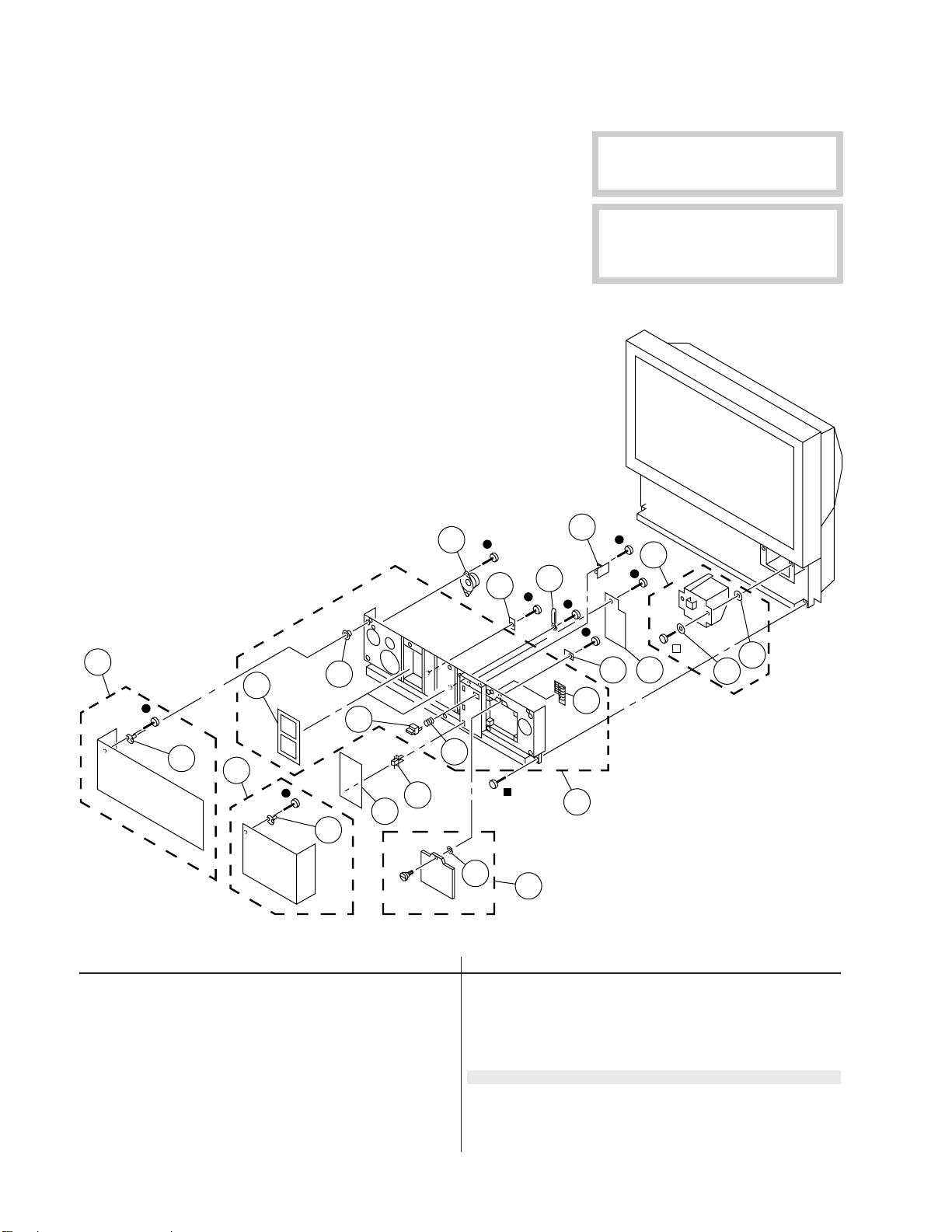
KL-W7000/W9000
RM-Y980
5-2. FRONT COVER [W7000]
r 7-685-648-79 +BVTP 3X12
p 7-685-663-79 +BVTP 4X16
π 7-683-421-04 HEXAGON SOCKET BOLT 4X12
63
64
71
The components identified by shading
and mark ¡ are critical for safety.
Replace only with part number specified.
Les composants identifiés per un tramé
et une marque
sécurité. Ne les remplacer que par une
piéce portant le numéro spécifié.
¡
sont critiques pour la
66
68
51
59
62
65
67
70
69
58
60
56
61
57
52
53
55
52
70
REF.NO. PART NO. DESCRIPTION REMARK REF.NO. PART NO. DESCRIPTION REMARK
51 X-4033-189-1 PANEL (L) ASSY, FRONT 52
52 4-054-709-01 STRIKE
53 X-4033-188-1 PANEL (R) ASSY, FRONT 52
54 X-4035-092-1 DOOR ASSY, LAMP 70
55 X-4035-091-1 DOOR ASSY
56 3-703-035-11 SHAFT, LID
57 X-4035-093-1 COVER ASSY, FRONT 58-62
58 4-051-286-31 BUTTON, MULTI
59 4-051-312-01 FILTER
60 4-051-285-01 BUTTON, POWER
61 4-820-917-01 SPRING, COMPRESSION
54
62 4-838-438-00 LATCH
63 1-505-207-11 SPEAKER (5.7CM)
64 *A-1390-763-A TB BOARD, COMPLETE
65 *A-1390-762-A TA BOARD, COMPLETE
66 *A-1372-396-A HB BOARD, COMPLETE
67 *A-1372-395-A HA BOARD, COMPLETE
68 ¡ A-1482-758-A LAMP BLOCK ASSY 69, 70
69 3-901-261-01 WASHER
70 *3-650-537-00 WASHER
71 *4-908-882-01 CLAMP
– 102 –
Page 59

KL-W7000/W9000
RM-Y980
5-3. SCREEN MIRROR BLOCK AND OPTICS UNIT [W7000]
r 7-685-648-79 +BVTP 3X12
p 7-685-663-79 +BVTP 4X16
7-685-167-19 WASHER HEAD SCREW +P 4X35
π
105
107
104
103
102
101
106
108
105
110
111
The components identified by shading
and mark ¡ are critical for safety.
Replace only with part number specified.
Les composants identifiés per un tramé
et une marque
sécurité. Ne les remplacer que par une
piéce portant le numéro spécifié.
¡
sont critiques pour la
109
126
106
116
113
117
114
101 X-4035-095-1 FRAME ASSY, SCREEN
102 4-056-485-11 SCREEN, CONTRAST
103 4-051-303-31 PLATE (L), DUFFUSION
104 4-051-297-11 PLATE (F), DUFFUSION
105 4-049-644-01 HOLDER, SCREEN (S1)
106 *4-033-782-02 HOLDER (S), SCREEN
107 *4-051-296-01 HOLDER, MIRROR
108 4-051-283-01 MIRROR
109 X-4035-096-1 COVER ASSY, MIRROR
110 4-374-745-11 CUSHION (A)
111 4-384-096-01 SCREW (4X16), TAPPING, +P
112 1-505-208-11 SPEAKER (10CM)
113 *A-1335-094-A C BOARD, COMPLETE
114 1-543-653-11 CORE ASSY, BEAD(DIVISION TYPE)
115
118
120
112
125
126
119
REF.NO. PART NO. DESCRIPTION REMARKREF.NO. PART NO. DESCRIPTION REMARK
115 *3-703-141-00 HOLDER, PRINTED CIRCUIT BOARD
116 A-1501-135-A PANEL BLOCK ASSY (B)
117 A-1501-209-A PANEL BLOCK ASSY (G)
118 A-1501-133-A PANEL BLOCK ASSY (R)
119 ¡*1-475-523-11 OPTICAL UNIT
120 *4-051-825-01 SHIELD, OPTICAL
121 *4-051-343-01 BASE, LAMP
122 ¡ 1-533-746-11 THERMOSTAT
123 X-4035-094-1 CABINET ASSY
124 *4-908-882-01 CLAMP
125 4-830-092-01 WASHER, FIBER
126 1-698-696-11 FAN, DC
121
124
122
123
– 103 –
Page 60

KL-W7000/W9000
RM-Y980
5-4. CHASSIS [W9000]
r 7-685-648-79 +BVTP 3X12
p 7-685-663-79 +BVTP 4X16
158
151
152
157
159
160
161
162
164
163
The components identified by shading
and mark ¡ are critical for safety.
Replace only with part number specified.
Les composants identifiés per un tramé
et une marque
sécurité. Ne les remplacer que par une
piéce portant le numéro spécifié.
¡
sont critiques pour la
167
165
166
168
155
156
154
153
152
169
170
REF.NO. PART NO. DESCRIPTION REMARK REF.NO. PART NO. DESCRIPTION REMARK
151 *A-1380-551-A K BOARD, COMPLETE
152 *3-703-141-00 HOLDER, PRINTED CIRCUIT BOARD
153 ¡ 1-473-545-13 POWER BLOCK
154 *4-051-332-01 BRACKET, MAIN
155 *A-1311-597-A G BOARD, COMPLETE
156 *A-1311-631-A GA BOARD, COMPLETE
157 *A-1298-254-A A BOARD, COMPLETE
158 *3-657-516-00 SUPPORT, PC BOARD
159 *A-1135-929-A BB BOARD, COMPLETE
160 *A-1373-632-A U BOARD, COMPLETE
161 *4-056-402-11 BRACKET, U
162 4-389-025-01 SCREW (M4) (EXT TOOTH WASHER)
163 ¡ 1-251-662-11 INLET, AC 3P(WITH NOISE FILTE)
165 4-329-127-00 CLAMP, CORD
164 4-052-345-01 SCREW, (3X8) (+K), TAPPING
166 4-033-719-01 BUCKLE, A
167 X-4035-090-1 COVER ASSY, REAR 165, 166
168 1-543-982-11 CORE, FERRITE
169 *4-057-132-01 PEDESTAL
170 4-378-522-01 SCREW, TAPPING, HEXAGON HEAD
– 104 –
Page 61

KL-W7000/W9000
RM-Y980
5-5. FRONT COVER [W9000]
r 7-685-648-79 +BVTP 3X12
p 7-685-663-79 +BVTP 4X16
π 7-683-421-04 HEXAGON SOCKET BOLT 4X12
213
214
221
The components identified by shading
and mark ¡ are critical for safety.
Replace only with part number specified.
Les composants identifiés per un tramé
et une marque
sécurité. Ne les remplacer que par une
piéce portant le numéro spécifié.
¡
sont critiques pour la
216
218
201
209
212
210
202
203
206
205
202
201 X-4033-189-1 PANEL (L) ASSY, FRONT 202
202 4-054-709-01 STRIKE
203 X-4033-188-1 PANEL (R) ASSY, FRONT 202
204 X-4035-092-1 DOOR ASSY, LAMP 220
205 X-4035-091-1 DOOR ASSY
206 3-703-035-11 SHAFT, LID
207 X-4035-093-1 COVER ASSY, FRONT 208-212
208 4-051-286-31 BUTTON, MULTI
209 4-051-312-01 FILTER
210 4-051-285-01 BUTTON, POWER
211 4-820-917-01 SPRING, COMPRESSION
215
217
219
208
211
207
220
220
REF.NO. PART NO. DESCRIPTION REMARKREF.NO. PART NO. DESCRIPTION REMARK
204
212 4-838-438-00 LATCH
213 1-505-207-11 SPEAKER (5.7CM)
214 *A-1390-763-A TB BOARD, COMPLETE
215 *A-1390-762-A TA BOARD, COMPLETE
216 *A-1372-396-A HB BOARD, COMPLETE
217 *A-1372-395-A HA BOARD, COMPLETE
218 ¡ A-1501-247-A LAMP BLOCK ASSY 219, 220
219 3-901-261-01 WASHER
220 *3-650-537-00 WASHER
221 *4-908-882-01 CLAMP
– 105 –
Page 62
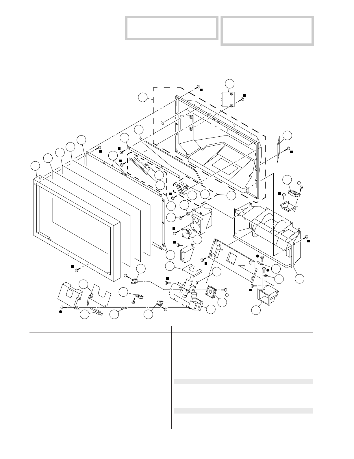
KL-W7000/W9000
RM-Y980
The components identified by shading
and mark ¡ are critical for safety.
Replace only with part number specified.
5-6. SCREEN MIRROR BLOCK AND OPTICS UNIT [W9000]
r 7-685-648-79 +BVTP 3X12
p 7-685-663-79 +BVTP 4X16
7-685-167-19 WASHER HEAD SCREW +P 4X35
π
258
Les composants identifiés per un tramé
et une marque
sécurité. Ne les remplacer que par une
piéce portant le numéro spécifié.
¡
sont critiques pour la
259
251
252
253
254
255
269
255
256
273
257
272
263
264
265
268
255
278
266
262
267
263
277
261
281
280
259
276
260
276
270 271
REF.NO. PART NO. DESCRIPTION REMARK REF.NO. PART NO. DESCRIPTION REMARK
251 X-4035-095-1 FRAME ASSY, SCREEN
252 4-056-485-11 SCREEN, CONTRAST
253 4-054-229-11 PLATE (L), DUFFUSION
254 4-054-230-11 PLATE (F), DUFFUSION
255 *4-055-161-01 HOLDER (50), SCREEN
256 *4-037-351-01 HOLDER, MIRROR
257 4-055-162-11 MIRROR (50)
258 X-4035-096-1 COVER ASSY, MIRROR
259 4-055-165-11 COVER (50), SERVICE
260 X-4035-094-1 CABINET ASSY
261 *X-4033-947-1 HOLDER (R) ASSY, MIRROR 262, 263
262 4-055-164-01 HOLDER (R), MIRROR
263 4-864-324-11 SPACER
264 4-055-163-01 HOLDER (L), MIRROR
265 *X-4033-946-1 HOLDER (L) ASSY, MIRROR 263, 264
266 4-374-745-11 CUSHION (A)
274
267 1-505-208-11 SPEAKER (10CM)
268 4-384-096-01 SCREW (4X16), TAPPING, +P
269 *A-1335-094-A C BOARD, COMPLETE
270 1-543-653-11 CORE ASSY, BEAD(DIVISION TYPE)
271 *3-703-141-00 HOLDER, PRINTED CIRCUIT BOARD
272 A-1501-135-A PANEL BLOCK ASSY (B)
273 A-1501-134-A PANEL BLOCK ASSY (G)
274 A-1501-133-A PANEL BLOCK ASSY (R)
275 ¡*1-475-523-11 OPTICAL UNIT
276 1-698-696-11 FAN, DC
277 4-830-092-01 WASHER, FIBER
278 *4-051-825-01 SHIELD, OPTICAL
279 *4-051-343-01 BASE, LAMP
280 ¡ 1-533-746-11 THERMOSTAT
281 *4-908-882-01 CLAMP
– 106 –
275
279
Page 63
The components identified by shading
and mark
Replace only with part number specified.
REF.NO. PART NO. DESCRIPTION REMARK REF.NO. PART NO. DESCRIPTION REMARK
NOTE:
The components identified by shading
and mark ¡ are critical for safety.
Replace only with part number specified.
When indicating parts by reference number,
please include the board name.
¡
are critical for safety.
Les composants identifiés per un tramé
et une marque
sécurité. Ne les remplacer que par une
piéce portant le numéro spécifié.
¡
sont critiques pour la
Les composants identifiés per un tramé
et une marque
sécurité. Ne les remplacer que par une
ELECTRICAL PARTS LIST
piéce portant le numéro spécifié.
• All variable and adjustable resistors have
characteristic curve B, unless otherwise
noted.
SECTION 6
¡
sont critiques pour la
RESISTORS
• All resistors are in ohms
• F : nonflammable
• Items marked " * " are not stocked since
they are seldom required for routine
service. Some delay should be
anticipated when ordering these items.
KL-W7000/W9000
(bb)
RM-Y980
REF.NO. PART NO. DESCRIPTION REMARK
*A-1135-929-ABB BOARD, COMPLETE
*****************************
4-042-930-01 CASE (BOTTOM LID), SHIELD
<CAPACITOR>
C3001 1-163-038-91 CERAMIC CHIP 0.1MF 25V
C3002 1-163-038-91 CERAMIC CHIP 0.1MF 25V
C3003 1-163-809-11 CERAMIC CHIP 0.047MF 10% 25V
C3004 1-107-823-11 CERAMIC CHIP 0.47MF 10% 16V
C3005 1-163-038-91 CERAMIC CHIP 0.1MF 25V
C3006 1-163-038-91 CERAMIC CHIP 0.1MF 25V
C3007 1-163-038-91 CERAMIC CHIP 0.1MF 25V
C3008 1-163-037-11 CERAMIC CHIP 0.022MF 10% 50V
C3009 1-164-489-11 CERAMIC CHIP 0.22MF 10% 16V
C3010 1-163-038-91 CERAMIC CHIP 0.1MF 25V
C3011 1-163-222-11 CERAMIC CHIP 5PF 0.25PF 50V
C3012 1-163-038-91 CERAMIC CHIP 0.1MF 25V
C3013 1-163-222-11 CERAMIC CHIP 5PF 0.25PF 50V
C3014 1-163-038-91 CERAMIC CHIP 0.1MF 25V
C3016 1-163-038-91 CERAMIC CHIP 0.1MF 25V
C3017 1-163-038-91 CERAMIC CHIP 0.1MF 25V
C3019 1-163-038-91 CERAMIC CHIP 0.1MF 25V
C3020 1-163-038-91 CERAMIC CHIP 0.1MF 25V
C3021 1-163-038-91 CERAMIC CHIP 0.1MF 25V
C3022 1-163-038-91 CERAMIC CHIP 0.1MF 25V
C3023 1-163-038-91 CERAMIC CHIP 0.1MF 25V
C3024 1-163-038-91 CERAMIC CHIP 0.1MF 25V
C3025 1-163-038-91 CERAMIC CHIP 0.1MF 25V
C3026 1-163-038-91 CERAMIC CHIP 0.1MF 25V
C3027 1-163-038-91 CERAMIC CHIP 0.1MF 25V
C3028 1-109-982-11 CERAMIC CHIP 1MF 10% 10V
C3029 1-163-038-91 CERAMIC CHIP 0.1MF 25V
C3030 1-109-982-11 CERAMIC CHIP 1MF 10% 10V
C3031 1-163-038-91 CERAMIC CHIP 0.1MF 25V
C3032 1-109-982-11 CERAMIC CHIP 1MF 10% 10V
C3035 1-126-964-11 ELECT 10MF 20% 50V
C3036 1-163-038-91 CERAMIC CHIP 0.1MF 25V
C3037 1-163-038-91 CERAMIC CHIP 0.1MF 25V
C3038 1-163-038-91 CERAMIC CHIP 0.1MF 25V
C3039 1-126-967-11 ELECT 47MF 20% 16V
C3041 1-163-038-91 CERAMIC CHIP 0.1MF 25V
C3042 1-163-038-91 CERAMIC CHIP 0.1MF 25V
REF.NO. PART NO. DESCRIPTION REMARK
C3043 1-163-038-91 CERAMIC CHIP 0.1MF 25V
C3044 1-163-038-91 CERAMIC CHIP 0.1MF 25V
C3045 1-163-038-91 CERAMIC CHIP 0.1MF 25V
C3046 1-163-038-91 CERAMIC CHIP 0.1MF 25V
C3047 1-163-038-91 CERAMIC CHIP 0.1MF 25V
C3048 1-163-038-91 CERAMIC CHIP 0.1MF 25V
C3049 1-163-038-91 CERAMIC CHIP 0.1MF 25V
C3050 1-127-532-11 ELECT(SOLID) 47MF 20% 6.3V
C3051 1-126-967-11 ELECT 47MF 20% 16V
C3052 1-163-038-91 CERAMIC CHIP 0.1MF 25V
C3053 1-163-038-91 CERAMIC CHIP 0.1MF 25V
C3054 1-163-038-91 CERAMIC CHIP 0.1MF 25V
C3055 1-163-038-91 CERAMIC CHIP 0.1MF 25V
C3056 1-163-038-91 CERAMIC CHIP 0.1MF 25V
C3057 1-163-038-91 CERAMIC CHIP 0.1MF 25V
C3058 1-163-038-91 CERAMIC CHIP 0.1MF 25V
C3060 1-163-038-91 CERAMIC CHIP 0.1MF 25V
C3061 1-163-038-91 CERAMIC CHIP 0.1MF 25V
C3062 1-163-038-91 CERAMIC CHIP 0.1MF 25V
C3071 1-126-935-11 ELECT 470MF 20% 16V
C3072 1-164-004-11 CERAMIC CHIP 0.1MF 10% 25V
C3202 1-163-239-11 CERAMIC CHIP 33PF 5% 50V
C3204 1-126-935-11 ELECT 470MF 20% 16V
C3205 1-163-038-91 CERAMIC CHIP 0.1MF 25V
C3213 1-126-935-11 ELECT 470MF 20% 16V
C3214 1-164-004-11 CERAMIC CHIP 0.1MF 10% 25V
C3215 1-126-967-11 ELECT 47MF 20% 16V
C3216 1-164-004-11 CERAMIC CHIP 0.1MF 10% 25V
C3221 1-164-004-11 CERAMIC CHIP 0.1MF 10% 25V
C3222 1-126-935-11 ELECT 470MF 20% 16V
C3227 1-163-038-91 CERAMIC CHIP 0.1MF 25V
C3228 1-126-967-11 ELECT 47MF 20% 16V
C3229 1-164-004-11 CERAMIC CHIP 0.1MF 10% 25V
C3230 1-126-967-11 ELECT 47MF 20% 16V
C3232 1-126-967-11 ELECT 47MF 20% 16V
C3233 1-126-967-11 ELECT 47MF 20% 16V
C3234 1-126-967-11 ELECT 47MF 20% 16V
C3235 1-126-967-11 ELECT 47MF 20% 16V
C3236 1-126-967-11 ELECT 47MF 20% 16V
C3237 1-126-967-11 ELECT 47MF 20% 16V
C3238 1-126-967-11 ELECT 47MF 20% 16V
C3240 1-126-964-11 ELECT 10MF 20% 50V
C3241 1-126-964-11 ELECT 10MF 20% 50V
– 107 –
Page 64

KL-W7000/W9000
RM-Y980
(bb)
REF.NO. PART NO. DESCRIPTION REMARK REF.NO. PART NO. DESCRIPTION REMARK
Les composants identifiés per un tramé
et une marque
sécurité. Ne les remplacer que par une
piéce portant le numéro spécifié.
¡
sont critiques pour la
The components identified by shading
and mark
Replace only with part number specified.
¡
are critical for safety.
C3242 1-126-964-11 ELECT 10MF 20% 50V
C3243 1-126-964-11 ELECT 10MF 20% 50V
C3244 1-163-113-00 CERAMIC CHIP 68PF 5% 50V
C3303 1-163-038-91 CERAMIC CHIP 0.1MF 25V
C3306 1-126-967-11 ELECT 47MF 20% 16V
C3310 1-126-964-11 ELECT 10MF 20% 50V
C3311 1-163-038-91 CERAMIC CHIP 0.1MF 25V
C3313 1-126-967-11 ELECT 47MF 20% 16V
C3314 1-126-964-11 ELECT 10MF 20% 50V
C3316 1-126-967-11 ELECT 47MF 20% 16V
C3318 1-163-038-91 CERAMIC CHIP 0.1MF 25V
C3321 1-126-964-11 ELECT 10MF 20% 50V
C3322 1-164-004-11 CERAMIC CHIP 0.1MF 10% 25V
C3324 1-126-967-11 ELECT 47MF 20% 16V
<CONNECTOR>
CN3001*1-564-522-11PLUG, CONNECTOR 7P
CN3002*1-564-525-11PLUG, CONNECTOR 10P
CN3003*1-564-526-31PLUG, CONNECTOR 11P
CN3004*1-564-518-11PLUG, CONNECTOR 3P
<FERRITE BEAD>
FB3201 1-216-295-91 SHORT 0
FB3202 1-216-295-91 SHORT 0
FB3203 1-216-295-91 SHORT 0
FB3205 1-216-295-91 SHORT 0
FB3206 1-216-295-91 SHORT 0
FB3207 1-216-295-91 SHORT 0
FB3208 1-216-295-91 SHORT 0
FB3209 1-216-295-91 SHORT 0
FB3210 1-216-295-91 SHORT 0
FB3211 1-216-295-91 SHORT 0
IC3006 8-759-478-92 IC TC7SET04FU(TE85R)
IC3007 8-759-485-79 IC TC7SET08FU-TE85L
IC3008 8-759-485-79 IC TC7SET08FU-TE85L
IC3009 8-759-271-88 IC TC7SHU04FU
IC3010 8-759-058-64 IC TC7S32FU(TE85R)
IC3011 8-759-085-51 IC NJM2284M
IC3301 8-752-386-04 IC CXD2303Q
IC3303 8-759-431-14 IC PQ3TZ53U
<COIL>
L3001 1-412-029-11 INDUCTOR CHIP 10UH
L3002 1-408-409-00 INDUCTOR 10UH
L3003 1-412-029-11 INDUCTOR CHIP 10UH
L3004 1-412-029-11 INDUCTOR CHIP 10UH
L3005 1-408-409-00 INDUCTOR 10UH
L3006 1-408-409-00 INDUCTOR 10UH
L3007 1-412-029-11 INDUCTOR CHIP 10UH
L3008 1-412-029-11 INDUCTOR CHIP 10UH
L3009 1-412-029-11 INDUCTOR CHIP 10UH
L3010 1-412-029-11 INDUCTOR CHIP 10UH
L3011 1-412-029-11 INDUCTOR CHIP 10UH
L3012 1-412-029-11 INDUCTOR CHIP 10UH
L3202 1-408-409-00 INDUCTOR 10UH
L3204 1-412-029-11 INDUCTOR CHIP 10UH
L3206 1-412-029-11 INDUCTOR CHIP 10UH
L3207 1-412-029-11 INDUCTOR CHIP 10UH
L3210 1-412-029-11 INDUCTOR CHIP 10UH
L3303 1-412-029-11 INDUCTOR CHIP 10UH
L3304 1-408-409-00 INDUCTOR 10UH
L3305 1-412-029-11 INDUCTOR CHIP 10UH
<TRANSISTOR>
FB3212 1-216-295-91 SHORT 0
<FILTER>
FL32041-233-446-11 FILTER, LOW PASS
FL32051-233-438-21 FILTER, LOW PASS
FL32061-233-438-21 FILTER, LOW PASS
FL32101-233-736-21 FILTER, EMI
FL32121-234-016-21 FILTER, EMI
FL32151-233-446-11 FILTER, LOW PASS
FL32161-234-021-11 FILTER, LOW PASS
FL32171-234-021-11 FILTER, LOW PASS
FL32181-234-021-11 FILTER, LOW PASS
FL32191-234-021-11 FILTER, LOW PASS
FL32221-234-016-21 FILTER, EMI
<IC>
IC3001 8-759-295-09 IC TLC2932IPW
IC3002 8-759-295-09 IC TLC2932IPW
IC3003 8-752-390-58 IC CXD2072AQ
IC3004 8-759-478-46 IC MSM548332-25TS-K
IC3005 8-759-478-46 IC MSM548332-25TS-K
Q3018 8-729-216-22 TRANSISTOR 2SA1162-G
Q3019 8-729-216-22 TRANSISTOR 2SA1162-G
Q3201 8-729-216-22 TRANSISTOR 2SA1162-G
Q3202 8-729-216-22 TRANSISTOR 2SA1162-G
Q3203 8-729-216-22 TRANSISTOR 2SA1162-G
Q3204 8-729-216-22 TRANSISTOR 2SA1162-G
Q3205 8-729-216-22 TRANSISTOR 2SA1162-G
Q3206 8-729-216-22 TRANSISTOR 2SA1162-G
Q3207 8-729-216-22 TRANSISTOR 2SA1162-G
Q3208 8-729-216-22 TRANSISTOR 2SA1162-G
Q3209 8-729-216-22 TRANSISTOR 2SA1162-G
Q3210 8-729-216-22 TRANSISTOR 2SA1162-G
Q3211 8-729-216-22 TRANSISTOR 2SA1162-G
Q3212 8-729-216-22 TRANSISTOR 2SA1162-G
Q3305 8-729-216-22 TRANSISTOR 2SA1162-G
Q3306 8-729-216-22 TRANSISTOR 2SA1162-G
Q3307 8-729-216-22 TRANSISTOR 2SA1162-G
Q3308 8-729-216-22 TRANSISTOR 2SA1162-G
<RESISTOR>
R3001 1-216-117-00 METAL GLAZE 680K 5% 1/10W
R3002 1-216-061-00 METAL GLAZE 3.3K 5% 1/10W
– 108 –
Page 65

The components identified by shading
and mark
Replace only with part number specified.
REF.NO. PART NO. DESCRIPTION REMARK REF.NO. PART NO. DESCRIPTION REMARK
¡
are critical for safety.
Les composants identifiés per un tramé
et une marque
sécurité. Ne les remplacer que par une
piéce portant le numéro spécifié.
¡
sont critiques pour la
KL-W7000/W9000
(bb)
RM-Y980
R3003 1-216-053-00 METAL GLAZE 1.5K 5% 1/10W
R3004 1-216-041-00 METAL GLAZE 470 5% 1/10W
R3005 1-216-295-91 SHORT 0
R3007 1-216-117-00 METAL GLAZE 680K 5% 1/10W
R3008 1-216-061-00 METAL GLAZE 3.3K 5% 1/10W
R3009 1-216-049-91 METAL GLAZE 1K 5% 1/10W
R3010 1-216-041-00 METAL GLAZE 470 5% 1/10W
R3011 1-216-295-91 SHORT 0
R3013 1-216-013-00 METAL GLAZE 33 5% 1/10W
R3014 1-216-121-91 METAL GLAZE 1M 5% 1/10W
R3015 1-216-025-91 METAL GLAZE 100 5% 1/10W
R3016 1-216-025-91 METAL GLAZE 100 5% 1/10W
R3017 1-216-025-91 METAL GLAZE 100 5% 1/10W
R3018 1-216-049-91 METAL GLAZE 1K 5% 1/10W
R3019 1-216-041-00 METAL GLAZE 470 5% 1/10W
R3020 1-216-295-91 SHORT 0
R3021 1-216-041-00 METAL GLAZE 470 5% 1/10W
R3022 1-216-295-91 SHORT 0
R3023 1-216-295-91 SHORT 0
R3029 1-216-025-91 METAL GLAZE 100 5% 1/10W
R3030 1-216-025-91 METAL GLAZE 100 5% 1/10W
R3032 1-216-633-11 METAL CHIP 180 0.50% 1/10W
R3037 1-216-025-91 METAL GLAZE 100 5% 1/10W
R3038 1-216-633-11 METAL CHIP 180 0.50% 1/10W
R3044 1-216-651-11 METAL CHIP 1K 0.50% 1/10W
R3045 1-216-651-11 METAL CHIP 1K 0.50% 1/10W
R3047 1-216-121-91 METAL GLAZE 1M 5% 1/10W
R3048 1-216-651-11 METAL CHIP 1K 0.50% 1/10W
R3049 1-216-295-91 SHORT 0
R3051 1-216-633-11 METAL CHIP 180 0.50% 1/10W
R3201 1-216-295-91 SHORT 0
R3202 1-216-295-91 SHORT 0
R3203 1-216-295-91 SHORT 0
R3204 1-216-033-00 METAL GLAZE 220 5% 1/10W
R3205 1-216-033-00 METAL GLAZE 220 5% 1/10W
R3206 1-216-033-00 METAL GLAZE 220 5% 1/10W
R3213 1-216-053-00 METAL GLAZE 1.5K 5% 1/10W
R3214 1-216-053-00 METAL GLAZE 1.5K 5% 1/10W
R3215 1-216-053-00 METAL GLAZE 1.5K 5% 1/10W
R3216 1-216-049-91 METAL GLAZE 1K 5% 1/10W
R3217 1-216-049-91 METAL GLAZE 1K 5% 1/10W
R3218 1-216-049-91 METAL GLAZE 1K 5% 1/10W
R3219 1-216-009-00 METAL GLAZE 22 5% 1/10W
R3220 1-216-009-00 METAL GLAZE 22 5% 1/10W
R3221 1-216-009-00 METAL GLAZE 22 5% 1/10W
R3225 1-216-033-00 METAL GLAZE 220 5% 1/10W
R3226 1-216-033-00 METAL GLAZE 220 5% 1/10W
R3227 1-216-033-00 METAL GLAZE 220 5% 1/10W
R3228 1-216-029-00 METAL GLAZE 150 5% 1/10W
R3229 1-216-029-00 METAL GLAZE 150 5% 1/10W
R3230 1-216-029-00 METAL GLAZE 150 5% 1/10W
R3231 1-216-647-11 METAL CHIP 680 0.50% 1/10W
R3232 1-216-647-11 METAL CHIP 680 0.50% 1/10W
R3233 1-216-651-11 METAL CHIP 1K 0.50% 1/10W
R3234 1-216-649-11 METAL CHIP 820 0.50% 1/10W
R3235 1-216-649-11 METAL CHIP 820 0.50% 1/10W
R3236 1-216-643-11 METAL CHIP 470 0.50% 1/10W
R3237 1-216-041-00 METAL GLAZE 470 5% 1/10W
R3238 1-216-041-00 METAL GLAZE 470 5% 1/10W
R3239 1-216-041-00 METAL GLAZE 470 5% 1/10W
R3240 1-216-295-91 SHORT 0
R3241 1-216-295-91 SHORT 0
R3242 1-216-295-91 SHORT 0
R3252 1-216-647-11 METAL CHIP 680 0.50% 1/10W
R3253 1-216-029-00 METAL GLAZE 150 5% 1/10W
R3254 1-216-647-11 METAL CHIP 680 0.50% 1/10W
R3263 1-216-295-91 SHORT 0
R3264 1-216-295-91 SHORT 0
R3265 1-216-025-91 METAL GLAZE 100 5% 1/10W
R3266 1-216-025-91 METAL GLAZE 100 5% 1/10W
R3267 1-216-025-91 METAL GLAZE 100 5% 1/10W
R3269 1-216-029-00 METAL GLAZE 150 5% 1/10W
R3271 1-216-295-91 SHORT 0
R3272 1-216-029-00 METAL GLAZE 150 5% 1/10W
R3273 1-216-029-00 METAL GLAZE 150 5% 1/10W
R3274 1-216-295-91 SHORT 0
R3275 1-216-295-91 SHORT 0
R3276 1-216-029-00 METAL GLAZE 150 5% 1/10W
R3280 1-216-033-00 METAL GLAZE 220 5% 1/10W
R3281 1-216-033-00 METAL GLAZE 220 5% 1/10W
R3282 1-216-009-00 METAL GLAZE 22 5% 1/10W
R3283 1-216-009-00 METAL GLAZE 22 5% 1/10W
R3284 1-216-041-00 METAL GLAZE 470 5% 1/10W
R3285 1-216-041-00 METAL GLAZE 470 5% 1/10W
R3286 1-216-295-91 SHORT 0
R3287 1-216-295-91 SHORT 0
R3288 1-216-649-11 METAL CHIP 820 0.50% 1/10W
R3289 1-216-649-11 METAL CHIP 820 0.50% 1/10W
R3301 1-216-295-91 SHORT 0
R3302 1-216-295-91 SHORT 0
R3305 1-216-025-91 METAL GLAZE 100 5% 1/10W
R3306 1-216-013-00 METAL GLAZE 33 5% 1/10W
R3307 1-216-295-91 SHORT 0
R3308 1-216-013-00 METAL GLAZE 33 5% 1/10W
R3309 1-216-607-11 METAL CHIP 15 0.50% 1/10W
R3311 1-216-607-11 METAL CHIP 15 0.50% 1/10W
R3316 1-216-049-91 METAL GLAZE 1K 5% 1/10W
R3317 1-216-049-91 METAL GLAZE 1K 5% 1/10W
R3318 1-216-625-11 METAL CHIP 82 0.50% 1/10W
R3319 1-216-627-11 METAL CHIP 100 0.50% 1/10W
R3321 1-216-627-11 METAL CHIP 100 0.50% 1/10W
R3322 1-216-639-11 METAL CHIP 330 0.50% 1/10W
R3325 1-216-295-91 SHORT 0
R3332 1-216-013-00 METAL GLAZE 33 5% 1/10W
R3334 1-216-295-91 SHORT 0
R3351 1-216-607-11 METAL CHIP 15 0.50% 1/10W
R3352 1-216-607-11 METAL CHIP 15 0.50% 1/10W
R3360 1-216-049-91 METAL GLAZE 1K 5% 1/10W
R3361 1-216-049-91 METAL GLAZE 1K 5% 1/10W
R3362 1-216-049-91 METAL GLAZE 1K 5% 1/10W
R3363 1-216-049-91 METAL GLAZE 1K 5% 1/10W
R3364 1-216-049-91 METAL GLAZE 1K 5% 1/10W
– 109 –
Page 66

KL-W7000/W9000
RM-Y980
(bb)(a)
REF.NO. PART NO. DESCRIPTION REMARK REF.NO. PART NO. DESCRIPTION REMARK
Les composants identifiés per un tramé
et une marque
sécurité. Ne les remplacer que par une
piéce portant le numéro spécifié.
¡
sont critiques pour la
The components identified by shading
and mark
Replace only with part number specified.
¡
are critical for safety.
R3365 1-216-049-91 METAL GLAZE 1K 5% 1/10W
R3366 1-216-049-91 METAL GLAZE 1K 5% 1/10W
R3367 1-216-049-91 METAL GLAZE 1K 5% 1/10W
R3368 1-216-049-91 METAL GLAZE 1K 5% 1/10W
R3369 1-216-049-91 METAL GLAZE 1K 5% 1/10W
R3370 1-216-049-91 METAL GLAZE 1K 5% 1/10W
R3371 1-216-049-91 METAL GLAZE 1K 5% 1/10W
R3372 1-216-049-91 METAL GLAZE 1K 5% 1/10W
R3373 1-216-049-91 METAL GLAZE 1K 5% 1/10W
R3374 1-216-049-91 METAL GLAZE 1K 5% 1/10W
R3375 1-216-049-91 METAL GLAZE 1K 5% 1/10W
R3376 1-216-049-91 METAL GLAZE 1K 5% 1/10W
R3377 1-216-049-91 METAL GLAZE 1K 5% 1/10W
R3378 1-216-049-91 METAL GLAZE 1K 5% 1/10W
R3379 1-216-049-91 METAL GLAZE 1K 5% 1/10W
R3380 1-216-049-91 METAL GLAZE 1K 5% 1/10W
R3381 1-216-049-91 METAL GLAZE 1K 5% 1/10W
R3382 1-216-049-91 METAL GLAZE 1K 5% 1/10W
R3383 1-216-049-91 METAL GLAZE 1K 5% 1/10W
<CRYSTAL>
X3001 1-767-262-11 VIBRATOR, CRYSTAL
********************************************************************************
*A-1298-254-AA BOARD, COMPLETE
***************************
4-382-854-01 SCREW (M3X8), P, SW (+) (IC1007)
<CAPACITOR>
C1001 1-104-664-11 ELECT 47MF 20% 25V
C1004 1-126-967-11 ELECT 47MF 20% 16V
C1007 1-163-038-91 CERAMIC CHIP 0.1MF 25V
C1013 1-104-664-11 ELECT 47MF 20% 25V
C1014 1-104-664-11 ELECT 47MF 20% 25V
C1015 1-163-038-91 CERAMIC CHIP 0.1MF 25V
C1016 1-163-038-91 CERAMIC CHIP 0.1MF 25V
C1017 1-163-038-91 CERAMIC CHIP 0.1MF 25V
C1018 1-163-038-91 CERAMIC CHIP 0.1MF 25V
C1019 1-163-038-91 CERAMIC CHIP 0.1MF 25V
C1020 1-163-038-91 CERAMIC CHIP 0.1MF 25V
C1021 1-163-038-91 CERAMIC CHIP 0.1MF 25V
C1022 1-163-038-91 CERAMIC CHIP 0.1MF 25V
C1102 1-163-251-11 CERAMIC CHIP 100PF 5% 50V
C1103 1-163-251-11 CERAMIC CHIP 100PF 5% 50V
C1104 1-163-251-11 CERAMIC CHIP 100PF 5% 50V
C1107 1-163-251-11 CERAMIC CHIP 100PF 5% 50V
C1108 1-126-925-11 ELECT 470MF 20% 10V
C1110 1-164-232-11 CERAMIC CHIP 0.01MF 10% 50V
C1113 1-164-232-11 CERAMIC CHIP 0.01MF 10% 50V
C1114 1-163-237-11 CERAMIC CHIP 27PF 5% 50V
C1117 1-163-237-11 CERAMIC CHIP 27PF 5% 50V
C1120 1-164-232-11 CERAMIC CHIP 0.01MF 10% 50V
C1121 1-163-251-11 CERAMIC CHIP 100PF 5% 50V
C1126 1-107-909-11 ELECT 47MF 20% 10V
C1127 1-164-232-11 CERAMIC CHIP 0.01MF 10% 50V
C1128 1-163-251-11 CERAMIC CHIP 100PF 5% 50V
C1129 1-163-251-11 CERAMIC CHIP 100PF 5% 50V
C1130 1-164-004-11 CERAMIC CHIP 0.1MF 10% 25V
C1131 1-163-251-11 CERAMIC CHIP 100PF 5% 50V
C1132 1-164-004-11 CERAMIC CHIP 0.1MF 10% 25V
C1133 1-163-251-11 CERAMIC CHIP 100PF 5% 50V
C1134 1-163-251-11 CERAMIC CHIP 100PF 5% 50V
C1135 1-163-251-11 CERAMIC CHIP 100PF 5% 50V
C1136 1-163-251-11 CERAMIC CHIP 100PF 5% 50V
C1137 1-163-251-11 CERAMIC CHIP 100PF 5% 50V
C1140 1-163-259-91 CERAMIC CHIP 220PF 5% 50V
C1141 1-104-760-11 CERAMIC CHIP 0.047MF 10% 50V
C1142 1-126-960-11 ELECT 1MF 20% 50V
C1144 1-164-232-11 CERAMIC CHIP 0.01MF 10% 50V
C1145 1-163-259-91 CERAMIC CHIP 220PF 5% 50V
C1146 1-126-960-11 ELECT 1MF 20% 50V
C1401 1-126-967-11 ELECT 47MF 20% 16V
C1402 1-163-038-91 CERAMIC CHIP 0.1MF 25V
C1403 1-163-038-91 CERAMIC CHIP 0.1MF 25V
C1404 1-126-767-11 ELECT 1000MF 20% 16V
C1409 1-126-961-11 ELECT 2.2MF 20% 50V
C1410 1-126-961-11 ELECT 2.2MF 20% 50V
C1411 1-126-960-11 ELECT 1MF 20% 50V
C1412 1-126-960-11 ELECT 1MF 20% 50V
C1413 1-126-964-11 ELECT 10MF 20% 50V
C1414 1-126-964-11 ELECT 10MF 20% 50V
C1415 1-126-964-11 ELECT 10MF 20% 50V
C1416 1-126-963-11 ELECT 4.7MF 20% 50V
C1417 1-126-964-11 ELECT 10MF 20% 50V
C1418 1-163-017-00 CERAMIC CHIP
C1419 1-126-964-11 ELECT 10MF 20% 50V
C1434 1-163-009-11 CERAMIC CHIP 0.001MF 10% 50V
C1435 1-130-489-00 FILM 0.033MF 5% 50V
C1436 1-137-399-11 FILM 0.1MF 5% 50V
C1437 1-130-489-00 FILM 0.033MF 5% 50V
C1438 1-130-489-00 FILM 0.033MF 5% 50V
C1439 1-104-664-11 ELECT 47MF 20% 25V
C1440 1-163-038-91 CERAMIC CHIP 0.1MF 25V
C1442 1-126-934-11 ELECT 220MF 20% 16V
C1443 1-163-259-91 CERAMIC CHIP 220PF 5% 50V
C1601 1-126-967-11 ELECT 47MF 20% 10V
C1602 1-164-232-11 CERAMIC CHIP 0.01MF 10% 50V
C1603 1-126-967-11 ELECT 47MF 20% 10V
C1604 1-163-235-11 CERAMIC CHIP 22PF 5% 50V
C1605 1-163-243-11 CERAMIC CHIP 47PF 5% 50V
C1608 1-163-235-11 CERAMIC CHIP 22PF 5% 50V
C1609 1-163-235-11 CERAMIC CHIP 22PF 5% 50V
C1610 1-163-235-11 CERAMIC CHIP 22PF 5% 50V
C1611 1-163-235-11 CERAMIC CHIP 22PF 5% 50V
C1612 1-163-235-11 CERAMIC CHIP 22PF 5% 50V
C1613 1-163-235-11 CERAMIC CHIP 22PF 5% 50V
C1614 1-163-251-11 CERAMIC CHIP 100PF 5% 50V
0.0047MF
10% 50V
– 110 –
Page 67

The components identified by shading
and mark
Replace only with part number specified.
REF.NO. PART NO. DESCRIPTION REMARK REF.NO. PART NO. DESCRIPTION REMARK
¡
are critical for safety.
Les composants identifiés per un tramé
et une marque
sécurité. Ne les remplacer que par une
piéce portant le numéro spécifié.
¡
sont critiques pour la
KL-W7000/W9000
(a)
RM-Y980
C1616 1-163-251-11 CERAMIC CHIP 100PF 5% 50V
C1617 1-163-251-11 CERAMIC CHIP 100PF 5% 50V
C1618 1-163-251-11 CERAMIC CHIP 100PF 5% 50V
C1619 1-163-251-11 CERAMIC CHIP 100PF 5% 50V
C1620 1-164-232-11 CERAMIC CHIP 0.01MF 10% 50V
C1621 1-164-232-11 CERAMIC CHIP 0.01MF 10% 50V
C2001 1-164-232-11 CERAMIC CHIP 0.01MF 10% 50V
C2002 1-107-909-11 ELECT 47MF 20% 16V
C2003 1-164-004-11 CERAMIC CHIP 0.1MF 10% 25V
C2004 1-164-004-11 CERAMIC CHIP 0.1MF 10% 25V
C2005 1-164-004-11 CERAMIC CHIP 0.1MF 10% 25V
C2006 1-107-715-11 ELECT 22MF 20% 25V
C2007 1-126-964-11 ELECT 10MF 20% 50V
C2008 1-164-004-11 CERAMIC CHIP 0.1MF 10% 25V
C2009 1-163-231-11 CERAMIC CHIP 15PF 5% 50V
C2010 1-107-906-11 ELECT 10MF 20% 50V
C2011 1-164-004-11 CERAMIC CHIP 0.1MF 10% 25V
C2012 1-107-906-11 ELECT 10MF 20% 50V
C2013 1-164-232-11 CERAMIC CHIP 0.01MF 10% 50V
C2014 1-128-526-11 ELECT 100MF 20% 10V
C2015 1-164-004-11 CERAMIC CHIP 0.1MF 10% 25V
C2017 1-164-004-11 CERAMIC CHIP 0.1MF 10% 25V
C2018 1-164-004-11 CERAMIC CHIP 0.1MF 10% 25V
C2019 1-107-909-11 ELECT 47MF 20% 10V
C2020 1-164-232-11 CERAMIC CHIP 0.01MF 10% 50V
C2021 1-164-004-11 CERAMIC CHIP 0.1MF 10% 25V
C2022 1-107-902-11 ELECT 1MF 20% 50V
C2023 1-107-902-11 ELECT 1MF 20% 50V
C2024 1-164-004-11 CERAMIC CHIP 0.1MF 10% 25V
C2025 1-107-909-11 ELECT 47MF 20% 10V
C2026 1-164-004-11 CERAMIC CHIP 0.1MF 10% 25V
C2027 1-163-227-11 CERAMIC CHIP 10PF 0.5PF 50V
C2028 1-163-009-11 CERAMIC CHIP 0.001MF 10% 50V
C2029 1-107-909-11 ELECT 47MF 20% 10V
C2030 1-164-232-11 CERAMIC CHIP 0.01MF 10% 50V
C2031 1-164-004-11 CERAMIC CHIP 0.1MF 10% 25V
C2032 1-163-137-00 CERAMIC CHIP 680PF 5% 50V
C2033 1-164-004-11 CERAMIC CHIP 0.1MF 10% 25V
C2034 1-164-232-11 CERAMIC CHIP 0.01MF 10% 50V
C2035 1-164-232-11 CERAMIC CHIP 0.01MF 10% 50V
C2036 1-164-232-11 CERAMIC CHIP 0.01MF 10% 50V
C2037 1-164-232-11 CERAMIC CHIP 0.01MF 10% 50V
C2038 1-163-259-91 CERAMIC CHIP 220PF 5% 50V
C2039 1-163-145-00 CERAMIC CHIP
C2040 1-164-232-11 CERAMIC CHIP 0.01MF 10% 50V
C2041 1-163-263-11 CERAMIC CHIP 330PF 5% 50V
C2042 1-107-909-11 ELECT 47MF 20% 10V
C2043 1-164-232-11 CERAMIC CHIP 0.01MF 10% 50V
C2044 1-164-004-11 CERAMIC CHIP 0.1MF 10% 25V
C2045 1-164-232-11 CERAMIC CHIP 0.01MF 10% 50V
C2046 1-107-905-11 ELECT 4.7MF 20% 50V
C2047 1-164-004-11 CERAMIC CHIP 0.1MF 10% 25V
C2048 1-164-004-11 CERAMIC CHIP 0.1MF 10% 25V
C2049 1-107-909-11 ELECT 47MF 20% 10V
C2050 1-164-232-11 CERAMIC CHIP 0.01MF 10% 50V
C2051 1-107-909-11 ELECT 47MF 20% 10V
0.0015MF
5% 50V
C2052 1-164-232-11 CERAMIC CHIP 0.01MF 10% 50V
C2053 1-164-004-11 CERAMIC CHIP 0.1MF 10% 25V
C2054 1-164-004-11 CERAMIC CHIP 0.1MF 10% 25V
C2055 1-164-004-11 CERAMIC CHIP 0.1MF 10% 25V
C2057 1-164-232-11 CERAMIC CHIP 0.01MF 10% 50V
C2058 1-164-232-11 CERAMIC CHIP 0.01MF 10% 50V
C2059 1-107-909-11 ELECT 47MF 20% 10V
C2060 1-164-232-11 CERAMIC CHIP 0.01MF 10% 50V
C2062 1-164-232-11 CERAMIC CHIP 0.01MF 10% 50V
C2063 1-164-004-11 CERAMIC CHIP 0.1MF 10% 25V
C2064 1-107-909-11 ELECT 47MF 20% 10V
C2065 1-164-232-11 CERAMIC CHIP 0.01MF 10% 50V
C2066 1-164-232-11 CERAMIC CHIP 0.01MF 10% 50V
C2067 1-164-004-11 CERAMIC CHIP 0.1MF 10% 25V
C2068 1-164-004-11 CERAMIC CHIP 0.1MF 10% 25V
C2069 1-164-004-11 CERAMIC CHIP 0.1MF 10% 25V
C2070 1-164-004-11 CERAMIC CHIP 0.1MF 10% 25V
C2071 1-164-004-11 CERAMIC CHIP 0.1MF 10% 25V
C2072 1-164-004-11 CERAMIC CHIP 0.1MF 10% 25V
C2073 1-107-909-11 ELECT 47MF 20% 10V
C2075 1-163-251-11 CERAMIC CHIP 100PF 5% 50V
C2076 1-164-004-11 CERAMIC CHIP 0.1MF 10% 25V
C2077 1-164-004-11 CERAMIC CHIP 0.1MF 10% 25V
C2078 1-164-004-11 CERAMIC CHIP 0.1MF 10% 25V
C2079 1-164-232-11 CERAMIC CHIP 0.01MF 10% 50V
C2080 1-164-004-11 CERAMIC CHIP 0.1MF 10% 25V
C2081 1-164-232-11 CERAMIC CHIP 0.01MF 10% 50V
C2082 1-107-906-11 ELECT 10MF 20% 50V
C2083 1-107-909-11 ELECT 47MF 20% 10V
C2084 1-164-232-11 CERAMIC CHIP 0.01MF 10% 50V
C2085 1-164-232-11 CERAMIC CHIP 0.01MF 10% 50V
C2086 1-107-902-11 ELECT 1MF 20% 50V
C2087 1-163-139-00 CERAMIC CHIP 820PF 10% 50V
C2088 1-107-906-11 ELECT 10MF 20% 50V
C2090 1-107-909-11 ELECT 47MF 20% 10V
C2091 1-164-232-11 CERAMIC CHIP 0.01MF 10% 50V
C2093 1-164-232-11 CERAMIC CHIP 0.01MF 10% 50V
C2096 1-107-909-11 ELECT 47MF 20% 10V
C2097 1-163-038-91 CERAMIC CHIP 0.1MF 25V
C2098 1-164-004-11 CERAMIC CHIP 0.1MF 10% 25V
C2099 1-164-004-11 CERAMIC CHIP 0.1MF 10% 25V
C2101 1-107-909-11 ELECT 47MF 20% 16V
C2102 1-164-232-11 CERAMIC CHIP 0.01MF 10% 50V
C2103 1-164-232-11 CERAMIC CHIP 0.01MF 10% 50V
C2104 1-164-161-11 CERAMIC CHIP
C2106 1-163-037-11 CERAMIC CHIP 0.022MF 10% 50V
C2107 1-107-902-11 ELECT 1MF 20% 50V
C2108 1-164-343-11 CERAMIC CHIP 0.056MF 10% 25V
C2109 1-107-909-11 ELECT 47MF 20% 10V
C2110 1-164-232-11 CERAMIC CHIP 0.01MF 10% 50V
C2112 1-163-009-11 CERAMIC CHIP 0.001MF 10% 50V
C2115 1-163-231-11 CERAMIC CHIP 15PF 5% 50V
C2116 1-164-232-11 CERAMIC CHIP 0.01MF 10% 50V
C2117 1-164-232-11 CERAMIC CHIP 0.01MF 10% 50V
C2118 1-107-906-11 ELECT 10MF 20% 50V
C2119 1-107-906-11 ELECT 10MF 20% 50V
0.0022MF
10% 50V
– 111 –
Page 68

KL-W7000/W9000
RM-Y980
(a)
REF.NO. PART NO. DESCRIPTION REMARK REF.NO. PART NO. DESCRIPTION REMARK
Les composants identifiés per un tramé
et une marque
sécurité. Ne les remplacer que par une
piéce portant le numéro spécifié.
¡
sont critiques pour la
The components identified by shading
and mark
Replace only with part number specified.
¡
are critical for safety.
C2120 1-163-275-11 CERAMIC CHIP 0.001MF 5% 50V
C2121 1-104-563-11 FILM CHIP 0.1MF 5% 16V
C2122 1-163-009-11 CERAMIC CHIP 0.001MF 10% 50V
C2123 1-104-563-11 FILM CHIP 0.1MF 5% 16V
C2124 1-163-275-11 CERAMIC CHIP 0.001MF 5% 50V
C2125 1-164-232-11 CERAMIC CHIP 0.01MF 10% 50V
C2126 1-107-909-11 ELECT 47MF 20% 16V
C2127 1-163-038-91 CERAMIC CHIP 0.1MF 25V
C2128 1-107-909-11 ELECT 47MF 20% 16V
C2129 1-163-038-91 CERAMIC CHIP 0.1MF 25V
C2130 1-163-038-91 CERAMIC CHIP 0.1MF 25V
C2140 1-163-243-11 CERAMIC CHIP 47PF 5% 50V
C2190 1-164-232-11 CERAMIC CHIP 0.01MF 10% 50V
C4002 1-163-235-11 CERAMIC CHIP 22PF 5% 50V
C4005 1-163-038-91 CERAMIC CHIP 0.1MF 25V
C4006 1-163-038-91 CERAMIC CHIP 0.1MF 25V
C4007 1-163-038-91 CERAMIC CHIP 0.1MF 25V
C4008 1-163-038-91 CERAMIC CHIP 0.1MF 25V
C4009 1-126-964-11 ELECT 10MF 20% 50V
C4010 1-126-960-11 ELECT 1MF 20% 50V
C4011 1-163-038-91 CERAMIC CHIP 0.1MF 25V
C4012 1-164-232-11 CERAMIC CHIP 0.01MF 10% 50V
C4013 1-126-933-11 ELECT 100MF 20% 16V
C4014 1-165-320-11 CERAMIC CHIP 0.47MF 10% 16V
C4015 1-164-232-11 CERAMIC CHIP 0.01MF 10% 50V
C4016 1-126-964-11 ELECT 10MF 20% 50V
C4018 1-126-933-11 ELECT 100MF 20% 16V
C4019 1-164-232-11 CERAMIC CHIP 0.01MF 10% 50V
C4021 1-164-232-11 CERAMIC CHIP 0.01MF 10% 50V
C4022 1-164-232-11 CERAMIC CHIP 0.01MF 10% 50V
C4023 1-164-232-11 CERAMIC CHIP 0.01MF 10% 50V
C4025 1-164-232-11 CERAMIC CHIP 0.01MF 10% 50V
C4026 1-164-232-11 CERAMIC CHIP 0.01MF 10% 50V
C4027 1-164-232-11 CERAMIC CHIP 0.01MF 10% 50V
C4028 1-164-232-11 CERAMIC CHIP 0.01MF 10% 50V
C4064 1-126-927-11 ELECT 2200MF 20% 10V
C4065 1-164-232-11 CERAMIC CHIP 0.01MF 10% 50V
C4066 1-126-927-11 ELECT 2200MF 20% 10V
C4067 1-164-232-11 CERAMIC CHIP 0.01MF 10% 50V
C4068 1-163-251-11 CERAMIC CHIP 100PF 5% 50V
C4069 1-164-232-11 CERAMIC CHIP 0.01MF 10% 50V
C4071 1-164-232-11 CERAMIC CHIP 0.01MF 10% 50V
C4072 1-164-232-11 CERAMIC CHIP 0.01MF 10% 50V
C4073 1-164-232-11 CERAMIC CHIP 0.01MF 10% 50V
C4080 1-163-259-91 CERAMIC CHIP 220PF 5% 50V
C4081 1-126-964-11 ELECT 10MF 20% 50V
C4085 1-164-232-11 CERAMIC CHIP 0.01MF 10% 50V
C4090 1-126-967-11 ELECT 47MF 20% 16V
C4096 1-164-232-11 CERAMIC CHIP 0.01MF 10% 50V
C4097 1-126-933-11 ELECT 100MF 20% 16V
C4098 1-164-232-11 CERAMIC CHIP 0.01MF 10% 50V
C4099 1-126-933-11 ELECT 100MF 20% 16V
C4100 1-163-038-91 CERAMIC CHIP 0.1MF 25V
C4201 1-126-964-11 ELECT 10MF 20% 50V
C4202 1-126-964-11 ELECT 10MF 20% 50V
C4203 1-126-967-11 ELECT 47MF 20% 16V
C4204 1-164-232-11 CERAMIC CHIP 0.01MF 10% 50V
C4205 1-126-933-11 ELECT 100MF 20% 16V
C4211 1-126-964-11 ELECT 10MF 20% 50V
C4212 1-126-964-11 ELECT 10MF 20% 50V
C4213 1-126-967-11 ELECT 47MF 20% 16V
C4221 1-126-964-11 ELECT 10MF 20% 50V
C4222 1-126-964-11 ELECT 10MF 20% 50V
C4223 1-126-967-11 ELECT 47MF 20% 16V
C4224 1-164-232-11 CERAMIC CHIP 0.01MF 10% 50V
C4225 1-126-933-11 ELECT 100MF 20% 16V
C4230 1-164-004-11 CERAMIC CHIP 0.1MF 10% 25V
C4231 1-164-004-11 CERAMIC CHIP 0.1MF 10% 25V
C4232 1-126-967-11 ELECT 47MF 20% 16V
C4029 1-164-232-11 CERAMIC CHIP 0.01MF 10% 50V
C4030 1-164-232-11 CERAMIC CHIP 0.01MF 10% 50V
C4031 1-107-909-11 ELECT 47MF 20% 16V
C4032 1-164-004-11 CERAMIC CHIP 0.1MF 10% 25V
C4035 1-110-501-11 CERAMIC CHIP 0.33MF 10% 16V
C4036 1-110-501-11 CERAMIC CHIP 0.33MF 10% 16V
C4037 1-110-501-11 CERAMIC CHIP 0.33MF 10% 16V
C4039 1-163-275-11 CERAMIC CHIP 0.001MF 5% 50V
C4044 1-110-501-11 CERAMIC CHIP 0.33MF 10% 16V
C4045 1-110-501-11 CERAMIC CHIP 0.33MF 10% 16V
C4046 1-110-501-11 CERAMIC CHIP 0.33MF 10% 16V
C4047 1-164-232-11 CERAMIC CHIP 0.01MF 10% 50V
C4048 1-164-232-11 CERAMIC CHIP 0.01MF 10% 50V
C4049 1-164-232-11 CERAMIC CHIP 0.01MF 10% 50V
C4050 1-164-232-11 CERAMIC CHIP 0.01MF 10% 50V
C4051 1-163-113-00 CERAMIC CHIP 68PF 5% 50V
C4052 1-126-933-11 ELECT 100MF 20% 16V
C4053 1-164-232-11 CERAMIC CHIP 0.01MF 10% 50V
C4055 1-126-964-11 ELECT 10MF 20% 50V
C4056 1-164-232-11 CERAMIC CHIP 0.01MF 10% 50V
C4063 1-164-232-11 CERAMIC CHIP 0.01MF 10% 50V
<CONNECTOR>
CN1001*1-766-957-11 CONNECTOR, BOARD TO BOARD 20P
CN1002*1-766-957-11 CONNECTOR, BOARD TO BOARD 20P
CN1003*1-564-507-11 PLUG, CONNECTOR 4P
CN1005*1-564-513-11 PLUG, CONNECTOR 10P
CN1006 1-764-812-11 CONNECTOR, BOARD TO BOARD 11P
CN1008*1-564-506-11 PLUG, CONNECTOR 3P
CN1009*1-564-512-11 PLUG, CONNECTOR 9P
CN1011*1-564-506-11 PLUG, CONNECTOR 3P
CN1012*1-564-512-11 PLUG, CONNECTOR 9P
CN1013 1-695-915-11 TAB (CONTACT)
CN1014 1-695-915-11 TAB (CONTACT)
CN1015 1-695-915-11 TAB (CONTACT)
CN1016 1-695-915-11 TAB (CONTACT)
CN1402*1-564-511-11 PLUG, CONNECTOR 8P
CN4003*1-564-511-11 PLUG, CONNECTOR 8P
CN4005 1-564-513-11 PLUG, CONNECTOR 10P
CN4006*1-564-512-11 PLUG, CONNECTOR 9P
– 112 –
Page 69

The components identified by shading
and mark
Replace only with part number specified.
REF.NO. PART NO. DESCRIPTION REMARK REF.NO. PART NO. DESCRIPTION REMARK
¡
are critical for safety.
Les composants identifiés per un tramé
et une marque
sécurité. Ne les remplacer que par une
piéce portant le numéro spécifié.
¡
sont critiques pour la
KL-W7000/W9000
(a)
RM-Y980
<DIODE>
D1011 8-719-404-49 DIODE MA111
D1025 8-719-404-49 DIODE MA111
D1031 8-719-158-15 ZENER DIODE RD5.6SB
D1032 8-719-158-15 ZENER DIODE RD5.6SB
D1102 8-719-404-49 DIODE MA111
D1103 8-719-404-49 DIODE MA111
D1104 8-719-158-15 ZENER DIODE RD5.6SB
D1105 8-719-158-15 ZENER DIODE RD5.6SB
D1401 8-719-158-39 ZENER DIODE RD10SB
D1402 8-719-158-39 ZENER DIODE RD10SB
D1405 8-719-404-49 DIODE MA111
D1406 8-719-404-49 DIODE MA111
D1407 8-719-404-49 DIODE MA111
D1408 8-719-404-49 DIODE MA111
D1601 8-719-801-78 DIODE 1SS184
D1605 8-719-404-49 DIODE MA111
D1606 8-719-404-49 DIODE MA111
D2001 8-719-404-49 DIODE MA111
D2002 8-719-031-68 DIODE HVU359TRF
D2004 8-719-976-88 ZENER DIODE DTZ3.9B
D2005 8-719-976-88 ZENER DIODE DTZ3.9B
D2006 8-719-404-49 DIODE MA111
D2008 8-719-404-49 DIODE MA111
D2009 8-719-404-49 DIODE MA111
D2010 8-719-404-49 DIODE MA111
FL20201-233-520-21 FILTER, EMI
FL20211-233-520-21 FILTER, EMI
FL20221-233-520-21 FILTER, EMI
<IC>
IC1007 8-759-390-51 IC UPC2409AHF
IC1008 8-759-054-12 IC PQ09RA1
IC1101 8-759-487-96 IC HD6473947-IT-OTP
IC1102 8-759-352-91 IC PST9143NL
IC1103 8-759-454-79 IC 24LC16BT/SN
IC1106 8-759-013-86 IC MC74HC4066F
IC1401 8-759-172-60 IC TA8776N
IC1601 8-752-890-27 IC CXP853P40AQ-3-035
IC1602 8-759-042-02 IC S-80743AL-A7-S
IC2001 8-759-161-24 IC UPC659AGS-E2
IC2003 8-759-296-53 IC UPC1862GS-E2
IC2004 8-752-376-20 IC CXD2052Q
IC2006 8-759-360-80 IC UPD6487GF-3BA
IC2007 8-759-033-03 IC MC74F08M
IC2008 8-759-167-20 IC UPD42280GU-30
IC2009 8-759-297-80 IC MSM514222B-30GS-KR1
IC2011 8-759-083-11 IC LA7217M
IC2012 8-759-081-44 IC TC74VHC04F
IC2101 8-759-150-61 IC UPC78L05T
IC2102 8-759-150-61 IC UPC78L05T
D2011 8-719-404-49 DIODE MA111
D4001 8-719-404-49 DIODE MA111
D4002 8-719-404-49 DIODE MA111
D4005 8-719-031-68 DIODE HVU359TRF
D4006 8-719-031-68 DIODE HVU359TRF
D4007 8-719-031-68 DIODE HVU359TRF
D4008 8-719-031-68 DIODE HVU359TRF
D4009 8-719-031-68 DIODE HVU359TRF
D4010 8-719-031-68 DIODE HVU359TRF
D4011 8-719-031-68 DIODE HVU359TRF
D4012 8-719-031-68 DIODE HVU359TRF
<FERRITE BEAD>
FB1601 1-412-364-11 INDUCTOR 0UH
FB1602 1-412-364-11 INDUCTOR 0UH
FB2002 1-414-234-11 INDUCTOR 0UH
FB2037 1-414-234-11 INDUCTOR 0UH
<FILTER>
FL20011-239-847-11 FILTER, LOW PASS
FL20021-233-535-11 FILTER, LOW PASS
FL20031-233-534-11 FILTER, LOW PASS
FL20041-233-535-11 FILTER, LOW PASS
FL20051-233-536-11 FILTER, LOW PASS
FL20061-233-536-11 FILTER, LOW PASS
FL20071-239-847-11 FILTER, LOW PASS
FL20151-233-539-21 FILTER, EMI
FL20191-233-520-21 FILTER, EMI
IC4001 8-759-009-46 IC MC14528BF
IC4002 8-752-072-88 IC CXA2011Q
IC4003 8-752-070-54 IC CXA1839Q-T6
IC4004 8-752-058-68 IC CXA1315M
IC4008 8-759-234-20 IC TC7S08F
IC4009 8-759-300-71 IC HD14053BFP
IC4011 8-752-072-88 IC CXA2011Q
<CHIP CONDUCTOR>
JR4001 1-216-295-91 SHORT 0
<COIL>
L1101 1-408-417-00 INDUCTOR 47UH
L1102 1-408-417-00 INDUCTOR 47UH
L1401 1-408-607-31 INDUCTOR 22UH
L1402 1-408-607-31 INDUCTOR 22UH
L1601 1-408-607-31 INDUCTOR 22UH
L1602 1-408-403-00 INDUCTOR 3.3UH
L2001 1-408-408-00 INDUCTOR 8.2UH
L2002 1-408-398-00 INDUCTOR 1.2UH
L2003 1-412-938-61 INDUCTOR 0.82UH
L2004 1-408-398-00 INDUCTOR 1.2UH
L2006 1-408-398-00 INDUCTOR 1.2UH
L2007 1-408-398-00 INDUCTOR 1.2UH
L2008 1-408-398-00 INDUCTOR 1.2UH
L2009 1-408-412-00 INDUCTOR 18UH
L2010 1-408-408-00 INDUCTOR 8.2UH
– 113 –
Page 70

KL-W7000/W9000
RM-Y980
(a)
REF.NO. PART NO. DESCRIPTION REMARK REF.NO. PART NO. DESCRIPTION REMARK
Les composants identifiés per un tramé
et une marque
sécurité. Ne les remplacer que par une
piéce portant le numéro spécifié.
¡
sont critiques pour la
The components identified by shading
and mark
Replace only with part number specified.
¡
are critical for safety.
L2011 1-408-412-00 INDUCTOR 18UH
L4001 1-408-412-00 INDUCTOR 18UH
L4002 1-408-409-00 INDUCTOR 10UH
L4003 1-408-607-31 INDUCTOR 22UH
L4004 1-408-409-00 INDUCTOR 10UH
L4005 1-408-607-31 INDUCTOR 22UH
L4006 1-408-607-31 INDUCTOR 22UH
L4007 1-408-417-00 INDUCTOR 47UH
L4008 1-408-607-31 INDUCTOR 22UH
L4009 1-408-607-31 INDUCTOR 22UH
L4010 1-408-607-31 INDUCTOR 22UH
L4011 1-408-409-00 INDUCTOR 10UH
<TRANSISTOR>
Q1101 8-729-422-54 TRANSISTOR XN4215
Q1102 8-729-216-22 TRANSISTOR 2SA1162-G
Q1103 8-729-216-22 TRANSISTOR 2SA1162-G
Q1105 8-729-216-22 TRANSISTOR 2SA1162-G
Q1108 8-729-216-22 TRANSISTOR 2SA1162-G
Q1408 8-729-216-22 TRANSISTOR 2SA1162-G
Q1409 8-729-422-27 TRANSISTOR 2SD601A-Q
Q1410 8-729-216-22 TRANSISTOR 2SA1162-G
Q1601 8-729-216-22 TRANSISTOR 2SA1162-G
Q1602 8-729-216-22 TRANSISTOR 2SA1162-G
Q1603 8-729-216-22 TRANSISTOR 2SA1162-G
Q1604 8-729-216-22 TRANSISTOR 2SA1162-G
Q1605 8-729-216-22 TRANSISTOR 2SA1162-G
Q1606 8-729-422-27 TRANSISTOR 2SD601A-Q
Q1607 8-729-422-27 TRANSISTOR 2SD601A-Q
Q1608 8-729-422-27 TRANSISTOR 2SD601A-Q
Q2001 8-729-422-27 TRANSISTOR 2SD601A-Q
Q2002 8-729-422-27 TRANSISTOR 2SD601A-Q
Q2003 8-729-422-27 TRANSISTOR 2SD601A-Q
Q2004 8-729-216-22 TRANSISTOR 2SA1162-G
Q2031 8-729-422-27 TRANSISTOR 2SD601A-Q
Q2035 8-729-216-22 TRANSISTOR 2SA1162-G
Q2036 8-729-216-22 TRANSISTOR 2SA1162-G
Q2037 8-729-216-22 TRANSISTOR 2SA1162-G
Q2041 8-729-422-27 TRANSISTOR 2SD601A-Q
Q2050 8-729-422-27 TRANSISTOR 2SD601A-Q
Q2051 8-729-216-22 TRANSISTOR 2SA1162-G
Q2052 8-729-216-22 TRANSISTOR 2SA1162-G
Q2061 8-729-422-27 TRANSISTOR 2SD601A-Q
Q2062 8-729-422-27 TRANSISTOR 2SD601A-Q
Q4001 8-729-216-22 TRANSISTOR 2SA1162-G
Q4002 8-729-216-22 TRANSISTOR 2SA1162-G
Q4003 8-729-216-22 TRANSISTOR 2SA1162-G
Q4004 8-729-422-27 TRANSISTOR 2SD601A-Q
Q4005 8-729-422-27 TRANSISTOR 2SD601A-Q
Q4006 8-729-422-27 TRANSISTOR 2SD601A-Q
Q4007 8-729-422-27 TRANSISTOR 2SD601A-Q
Q4008 8-729-216-22 TRANSISTOR 2SA1162-G
Q4009 8-729-216-22 TRANSISTOR 2SA1162-G
Q4010 8-729-216-22 TRANSISTOR 2SA1162-G
Q4018 8-729-422-27 TRANSISTOR 2SD601A-Q
Q4019 8-729-422-27 TRANSISTOR 2SD601A-Q
Q4020 8-729-422-27 TRANSISTOR 2SD601A-Q
Q4021 8-729-422-27 TRANSISTOR 2SD601A-Q
Q4025 8-729-403-27 TRANSISTOR XN4401
Q4026 8-729-422-27 TRANSISTOR 2SD601A-Q
Q4027 8-729-422-27 TRANSISTOR 2SD601A-Q
Q4028 8-729-422-27 TRANSISTOR 2SD601A-Q
Q4034 8-729-216-22 TRANSISTOR 2SA1162-G
Q4035 8-729-422-27 TRANSISTOR 2SD601A-Q
Q4041 8-729-422-27 TRANSISTOR 2SD601A-Q
Q4043 8-729-422-27 TRANSISTOR 2SD601A-Q
Q4044 8-729-216-22 TRANSISTOR 2SA1162-G
Q4045 8-729-216-22 TRANSISTOR 2SA1162-G
Q2005 8-729-216-22 TRANSISTOR 2SA1162-G
Q2007 8-729-422-27 TRANSISTOR 2SD601A-Q
Q2008 8-729-216-22 TRANSISTOR 2SA1162-G
Q2009 8-729-422-27 TRANSISTOR 2SD601A-Q
Q2010 8-729-422-27 TRANSISTOR 2SD601A-Q
Q2011 8-729-216-22 TRANSISTOR 2SA1162-G
Q2012 8-729-216-22 TRANSISTOR 2SA1162-G
Q2013 8-729-216-22 TRANSISTOR 2SA1162-G
Q2014 8-729-216-22 TRANSISTOR 2SA1162-G
Q2015 8-729-216-22 TRANSISTOR 2SA1162-G
Q2016 8-729-216-22 TRANSISTOR 2SA1162-G
Q2017 8-729-216-22 TRANSISTOR 2SA1162-G
Q2018 8-729-216-22 TRANSISTOR 2SA1162-G
Q2019 8-729-216-22 TRANSISTOR 2SA1162-G
Q2020 8-729-422-27 TRANSISTOR 2SD601A-Q
Q2021 8-729-422-27 TRANSISTOR 2SD601A-Q
Q2024 8-729-216-22 TRANSISTOR 2SA1162-G
Q2027 8-729-216-22 TRANSISTOR 2SA1162-G
Q2028 8-729-216-22 TRANSISTOR 2SA1162-G
Q2029 8-729-216-22 TRANSISTOR 2SA1162-G
Q2030 8-729-422-27 TRANSISTOR 2SD601A-Q
<RESISTOR>
R1002 1-216-025-91 METAL GLAZE 100 5% 1/10W
R1003 1-216-025-91 METAL GLAZE 100 5% 1/10W
R1004 1-216-025-91 METAL GLAZE 100 5% 1/10W
R1005 1-216-025-91 METAL GLAZE 100 5% 1/10W
R1006 1-216-025-91 METAL GLAZE 100 5% 1/10W
R1011 1-216-033-00 METAL GLAZE 220 5% 1/10W
R1012 1-216-049-91 METAL GLAZE 1K 5% 1/10W
R1013 1-216-033-00 METAL GLAZE 220 5% 1/10W
R1014 1-216-033-00 METAL GLAZE 220 5% 1/10W
R1015 1-216-033-00 METAL GLAZE 220 5% 1/10W
R1016 1-216-033-00 METAL GLAZE 220 5% 1/10W
R1017 1-216-033-00 METAL GLAZE 220 5% 1/10W
R1018 1-216-033-00 METAL GLAZE 220 5% 1/10W
R1101 1-216-065-00 METAL GLAZE 4.7K 5% 1/10W
R1102 1-216-065-00 METAL GLAZE 4.7K 5% 1/10W
R1103 1-216-073-00 METAL GLAZE 10K 5% 1/10W
R1104 1-216-049-91 METAL GLAZE 1K 5% 1/10W
R1105 1-216-033-00 METAL GLAZE 220 5% 1/10W
R1106 1-216-033-00 METAL GLAZE 220 5% 1/10W
R1107 1-216-037-00 METAL GLAZE 330 5% 1/10W
– 114 –
Page 71

The components identified by shading
and mark
Replace only with part number specified.
REF.NO. PART NO. DESCRIPTION REMARK REF.NO. PART NO. DESCRIPTION REMARK
¡
are critical for safety.
Les composants identifiés per un tramé
et une marque
sécurité. Ne les remplacer que par une
piéce portant le numéro spécifié.
¡
sont critiques pour la
KL-W7000/W9000
(a)
RM-Y980
R1108 1-216-073-00 METAL GLAZE 10K 5% 1/10W
R1111 1-216-121-91 METAL GLAZE 1M 5% 1/10W
R1112 1-216-073-00 METAL GLAZE 10K 5% 1/10W
R1113 1-216-073-00 METAL GLAZE 10K 5% 1/10W
R1115 1-216-049-91 METAL GLAZE 1K 5% 1/10W
R1119 1-216-033-00 METAL GLAZE 220 5% 1/10W
R1120 1-216-033-00 METAL GLAZE 220 5% 1/10W
R1122 1-216-025-91 METAL GLAZE 100 5% 1/10W
R1125 1-216-295-91 SHORT 0
R1128 1-216-065-00 METAL GLAZE 4.7K 5% 1/10W
R1129 1-216-065-00 METAL GLAZE 4.7K 5% 1/10W
R1130 1-216-033-00 METAL GLAZE 220 5% 1/10W
R1132 1-216-097-91 METAL GLAZE 100K 5% 1/10W
R1133 1-216-121-91 METAL GLAZE 1M 5% 1/10W
R1134 1-216-017-91 METAL GLAZE 47 5% 1/10W
R1135 1-216-073-00 METAL GLAZE 10K 5% 1/10W
R1138 1-216-017-91 METAL GLAZE 47 5% 1/10W
R1139 1-216-073-00 METAL GLAZE 10K 5% 1/10W
R1140 1-216-065-00 METAL GLAZE 4.7K 5% 1/10W
R1141 1-216-065-00 METAL GLAZE 4.7K 5% 1/10W
R1151 1-216-025-91 METAL GLAZE 100 5% 1/10W
R1154 1-216-025-91 METAL GLAZE 100 5% 1/10W
R1155 1-216-025-91 METAL GLAZE 100 5% 1/10W
R1156 1-216-049-91 METAL GLAZE 1K 5% 1/10W
R1157 1-216-295-91 SHORT 0
R1167 1-216-065-00 METAL GLAZE 4.7K 5% 1/10W
R1168 1-216-065-00 METAL GLAZE 4.7K 5% 1/10W
R1200 1-216-025-91 METAL GLAZE 100 5% 1/10W
R1201 1-216-025-91 METAL GLAZE 100 5% 1/10W
R1202 1-216-025-91 METAL GLAZE 100 5% 1/10W
R1203 1-216-049-91 METAL GLAZE 1K 5% 1/10W
R1204 1-216-047-91 METAL GLAZE 820 5% 1/10W
R1205 1-216-049-91 METAL GLAZE 1K 5% 1/10W
R1402 1-216-295-91 SHORT 0
R1403 1-216-295-91 SHORT 0
R1405 1-216-111-91 METAL GLAZE 390K 5% 1/10W
R1410 1-216-295-91 SHORT 0
R1411 1-216-037-00 METAL GLAZE 330 5% 1/10W
R1412 1-216-037-00 METAL GLAZE 330 5% 1/10W
R1413 1-216-295-91 SHORT 0
R1414 1-216-295-91 SHORT 0
R1439 1-215-866-11 METAL OXIDE 330 5% 1W F
R1442 1-216-025-91 METAL GLAZE 100 5% 1/10W
R1443 1-216-025-91 METAL GLAZE 100 5% 1/10W
R1444 1-216-065-00 METAL GLAZE 4.7K 5% 1/10W
R1445 1-216-089-91 METAL GLAZE 47K 5% 1/10W
R1446 1-216-073-00 METAL GLAZE 10K 5% 1/10W
R1447 1-216-081-00 METAL GLAZE 22K 5% 1/10W
R1448 1-216-033-00 METAL GLAZE 220 5% 1/10W
R1603 1-216-073-00 METAL GLAZE 10K 5% 1/10W
R1604 1-216-073-00 METAL GLAZE 10K 5% 1/10W
R1605 1-216-049-91 METAL GLAZE 1K 5% 1/10W
R1606 1-216-033-00 METAL GLAZE 220 5% 1/10W
R1607 1-216-049-91 METAL GLAZE 1K 5% 1/10W
R1608 1-216-057-00 METAL GLAZE 2.2K 5% 1/10W
R1609 1-216-057-00 METAL GLAZE 2.2K 5% 1/10W
R1610 1-216-035-00 METAL GLAZE 270 5% 1/10W
R1611 1-216-035-00 METAL GLAZE 270 5% 1/10W
R1612 1-216-049-91 METAL GLAZE 1K 5% 1/10W
R1613 1-216-035-00 METAL GLAZE 270 5% 1/10W
R1614 1-216-035-00 METAL GLAZE 270 5% 1/10W
R1615 1-216-049-91 METAL GLAZE 1K 5% 1/10W
R1616 1-216-035-00 METAL GLAZE 270 5% 1/10W
R1617 1-216-035-00 METAL GLAZE 270 5% 1/10W
R1618 1-216-049-91 METAL GLAZE 1K 5% 1/10W
R1619 1-216-039-00 METAL GLAZE 390 5% 1/10W
R1620 1-216-039-00 METAL GLAZE 390 5% 1/10W
R1621 1-216-039-00 METAL GLAZE 390 5% 1/10W
R1622 1-216-045-00 METAL GLAZE 680 5% 1/10W
R1623 1-216-045-00 METAL GLAZE 680 5% 1/10W
R1624 1-216-045-00 METAL GLAZE 680 5% 1/10W
R1625 1-216-049-91 METAL GLAZE 1K 5% 1/10W
R1626 1-216-073-00 METAL GLAZE 10K 5% 1/10W
R1627 1-216-073-00 METAL GLAZE 10K 5% 1/10W
R1628 1-216-073-00 METAL GLAZE 10K 5% 1/10W
R1629 1-216-073-00 METAL GLAZE 10K 5% 1/10W
R1630 1-216-295-91 SHORT 0
R1646 1-216-049-91 METAL GLAZE 1K 5% 1/10W
R2001 1-216-081-00 METAL GLAZE 22K 5% 1/10W
R2002 1-216-001-00 METAL GLAZE 10 5% 1/10W
R2003 1-216-049-91 METAL GLAZE 1K 5% 1/10W
R2004 1-216-077-00 METAL GLAZE 15K 5% 1/10W
R2005 1-216-055-00 METAL GLAZE 1.8K 5% 1/10W
R2006 1-216-017-91 METAL GLAZE 47 5% 1/10W
R2007 1-216-061-00 METAL GLAZE 3.3K 5% 1/10W
R2008 1-216-057-00 METAL GLAZE 2.2K 5% 1/10W
R2010 1-216-645-11 METAL CHIP 560 0.50% 1/10W
R2011 1-216-025-91 METAL GLAZE 100 5% 1/10W
R2012 1-216-061-00 METAL GLAZE 3.3K 5% 1/10W
R2013 1-216-075-00 METAL GLAZE 12K 5% 1/10W
R2014 1-216-638-11 METAL CHIP 300 0.50% 1/10W
R2015 1-216-061-00 METAL GLAZE 3.3K 5% 1/10W
R2016 1-216-669-11 METAL CHIP 5.6K 0.50% 1/10W
R2017 1-216-643-11 METAL CHIP 470 0.50% 1/10W
R2018 1-216-001-00 METAL GLAZE 10 5% 1/10W
R2019 1-216-097-91 METAL GLAZE 100K 5% 1/10W
R2021 1-216-039-00 METAL GLAZE 390 5% 1/10W
R2022 1-216-039-00 METAL GLAZE 390 5% 1/10W
R2024 1-216-683-11 METAL CHIP 22K 0.50% 1/10W
R2025 1-216-675-11 METAL CHIP 10K 0.50% 1/10W
R2026 1-216-023-00 METAL GLAZE 82 5% 1/10W
R2027 1-216-049-91 METAL GLAZE 1K 5% 1/10W
R2029 1-216-089-91 METAL GLAZE 47K 5% 1/10W
R2030 1-216-089-91 METAL GLAZE 47K 5% 1/10W
R2031 1-216-049-91 METAL GLAZE 1K 5% 1/10W
R2032 1-216-033-00 METAL GLAZE 220 5% 1/10W
R2033 1-216-033-00 METAL GLAZE 220 5% 1/10W
R2034 1-216-699-11 METAL CHIP 100K 0.50% 1/10W
R2035 1-216-665-11 METAL CHIP 3.9K 0.50% 1/10W
R2036 1-216-651-11 METAL CHIP 1K 0.50% 1/10W
R2037 1-216-097-91 METAL GLAZE 100K 5% 1/10W
R2038 1-216-693-11 METAL CHIP 56K 0.50% 1/10W
– 115 –
Page 72

KL-W7000/W9000
RM-Y980
(a)
REF.NO. PART NO. DESCRIPTION REMARK REF.NO. PART NO. DESCRIPTION REMARK
Les composants identifiés per un tramé
et une marque
sécurité. Ne les remplacer que par une
piéce portant le numéro spécifié.
¡
sont critiques pour la
The components identified by shading
and mark
Replace only with part number specified.
¡
are critical for safety.
R2039 1-216-059-00 METAL GLAZE 2.7K 5% 1/10W
R2040 1-216-057-00 METAL GLAZE 2.2K 5% 1/10W
R2042 1-216-035-00 METAL GLAZE 270 5% 1/10W
R2043 1-216-062-00 METAL GLAZE 3.6K 5% 1/10W
R2044 1-216-071-00 METAL GLAZE 8.2K 5% 1/10W
R2045 1-216-053-00 METAL GLAZE 1.5K 5% 1/10W
R2046 1-216-073-00 METAL GLAZE 10K 5% 1/10W
R2047 1-216-073-00 METAL GLAZE 10K 5% 1/10W
R2048 1-216-049-91 METAL GLAZE 1K 5% 1/10W
R2049 1-216-059-00 METAL GLAZE 2.7K 5% 1/10W
R2050 1-216-057-00 METAL GLAZE 2.2K 5% 1/10W
R2051 1-216-025-91 METAL GLAZE 100 5% 1/10W
R2052 1-216-057-00 METAL GLAZE 2.2K 5% 1/10W
R2053 1-216-043-91 METAL GLAZE 560 5% 1/10W
R2054 1-216-059-00 METAL GLAZE 2.7K 5% 1/10W
R2055 1-216-051-00 METAL GLAZE 1.2K 5% 1/10W
R2056 1-216-033-00 METAL GLAZE 220 5% 1/10W
R2057 1-216-049-91 METAL GLAZE 1K 5% 1/10W
R2059 1-216-295-91 SHORT 0
R2060 1-216-295-91 SHORT 0
R2061 1-216-295-91 SHORT 0
R2062 1-216-067-00 METAL GLAZE 5.6K 5% 1/10W
R2064 1-216-089-91 METAL GLAZE 47K 5% 1/10W
R2065 1-216-049-91 METAL GLAZE 1K 5% 1/10W
R2066 1-216-059-00 METAL GLAZE 2.7K 5% 1/10W
R2068 1-216-025-91 METAL GLAZE 100 5% 1/10W
R2069 1-216-023-00 METAL GLAZE 82 5% 1/10W
R2071 1-216-043-91 METAL GLAZE 560 5% 1/10W
R2072 1-216-023-00 METAL GLAZE 82 5% 1/10W
R2073 1-216-033-00 METAL GLAZE 220 5% 1/10W
R2074 1-216-067-00 METAL GLAZE 5.6K 5% 1/10W
R2076 1-216-049-91 METAL GLAZE 1K 5% 1/10W
R2077 1-216-295-91 SHORT 0
R2078 1-216-295-91 SHORT 0
R2079 1-216-634-11 METAL CHIP 200 0.50% 1/10W
R2080 1-216-049-91 METAL GLAZE 1K 5% 1/10W
R2081 1-216-295-91 SHORT 0
R2082 1-216-295-91 SHORT 0
R2083 1-216-295-91 SHORT 0
R2084 1-216-634-11 METAL CHIP 200 0.50% 1/10W
R2087 1-216-049-91 METAL GLAZE 1K 5% 1/10W
R2088 1-216-047-91 METAL GLAZE 820 5% 1/10W
R2089 1-216-295-91 SHORT 0
R2090 1-216-043-91 METAL GLAZE 560 5% 1/10W
R2091 1-216-634-11 METAL CHIP 200 0.50% 1/10W
R2094 1-216-067-00 METAL GLAZE 5.6K 5% 1/10W
R2096 1-216-651-11 METAL CHIP 1K 0.50% 1/10W
R2097 1-216-085-00 METAL GLAZE 33K 5% 1/10W
R2099 1-216-057-00 METAL GLAZE 2.2K 5% 1/10W
R2100 1-216-047-91 METAL GLAZE 820 5% 1/10W
R2101 1-216-073-00 METAL GLAZE 10K 5% 1/10W
R2102 1-216-049-91 METAL GLAZE 1K 5% 1/10W
R2103 1-216-043-91 METAL GLAZE 560 5% 1/10W
R2108 1-216-643-11 METAL CHIP 470 0.50% 1/10W
R2109 1-216-033-00 METAL GLAZE 220 5% 1/10W
R2111 1-216-043-91 METAL GLAZE 560 5% 1/10W
R2112 1-216-295-91 SHORT 0
R2113 1-216-067-00 METAL GLAZE 5.6K 5% 1/10W
R2125 1-216-047-91 METAL GLAZE 820 5% 1/10W
R2129 1-216-043-91 METAL GLAZE 560 5% 1/10W
R2130 1-216-295-91 SHORT 0
R2131 1-216-067-00 METAL GLAZE 5.6K 5% 1/10W
R2132 1-216-295-91 SHORT 0
R2133 1-216-295-91 SHORT 0
R2135 1-216-101-00 METAL GLAZE 150K 5% 1/10W
R2141 1-216-025-91 METAL GLAZE 100 5% 1/10W
R2144 1-216-295-91 SHORT 0
R2145 1-216-623-11 METAL CHIP 68 0.50% 1/10W
R2150 1-216-025-91 METAL GLAZE 100 5% 1/10W
R2151 1-216-049-91 METAL GLAZE 1K 5% 1/10W
R2152 1-216-043-91 METAL GLAZE 560 5% 1/10W
R2153 1-216-053-00 METAL GLAZE 1.5K 5% 1/10W
R2154 1-216-063-91 METAL GLAZE 3.9K 5% 1/10W
R2155 1-216-049-91 METAL GLAZE 1K 5% 1/10W
R2157 1-216-037-00 METAL GLAZE 330 5% 1/10W
R2158 1-216-037-00 METAL GLAZE 330 5% 1/10W
R2159 1-216-097-91 METAL GLAZE 100K 5% 1/10W
R2160 1-216-037-00 METAL GLAZE 330 5% 1/10W
R2161 1-216-037-00 METAL GLAZE 330 5% 1/10W
R2162 1-216-097-91 METAL GLAZE 100K 5% 1/10W
R2171 1-216-031-00 METAL GLAZE 180 5% 1/10W
R2172 1-216-045-00 METAL GLAZE 680 5% 1/10W
R2173 1-216-677-11 METAL CHIP 12K 0.50% 1/10W
R2174 1-216-695-11 METAL CHIP 68K 0.50% 1/10W
R2175 1-216-097-91 METAL GLAZE 100K 5% 1/10W
R2176 1-216-687-11 METAL CHIP 33K 0.50% 1/10W
R2177 1-216-675-11 METAL CHIP 10K 0.50% 1/10W
R2178 1-216-065-00 METAL GLAZE 4.7K 5% 1/10W
R2179 1-216-073-00 METAL GLAZE 10K 5% 1/10W
R2180 1-218-756-11 METAL CHIP 150K 0.50% 1/10W
R2181 1-216-697-91 METAL CHIP 82K 0.50% 1/10W
R2182 1-216-073-00 METAL GLAZE 10K 5% 1/10W
R2183 1-218-762-11 METAL CHIP 270K 0.50% 1/10W
R2184 1-216-675-11 METAL CHIP 10K 0.50% 1/10W
R2185 1-216-684-91 METAL CHIP 24K 0.50% 1/10W
R2191 1-216-041-00 METAL GLAZE 470 5% 1/10W
R2192 1-216-041-00 METAL GLAZE 470 5% 1/10W
R2193 1-216-049-91 METAL GLAZE 1K 5% 1/10W
R2194 1-216-049-91 METAL GLAZE 1K 5% 1/10W
R2195 1-216-077-00 METAL GLAZE 15K 5% 1/10W
R2196 1-216-077-00 METAL GLAZE 15K 5% 1/10W
R2197 1-216-073-00 METAL GLAZE 10K 5% 1/10W
R2198 1-216-073-00 METAL GLAZE 10K 5% 1/10W
R2200 1-216-035-00 METAL GLAZE 270 5% 1/10W
R2201 1-216-035-00 METAL GLAZE 270 5% 1/10W
R2202 1-216-051-00 METAL GLAZE 1.2K 5% 1/10W
R2203 1-216-049-91 METAL GLAZE 1K 5% 1/10W
R2204 1-216-049-91 METAL GLAZE 1K 5% 1/10W
R2205 1-216-049-91 METAL GLAZE 1K 5% 1/10W
R2211 1-216-065-00 METAL GLAZE 4.7K 5% 1/10W
R2212 1-216-031-00 METAL GLAZE 180 5% 1/10W
R2213 1-216-065-00 METAL GLAZE 4.7K 5% 1/10W
– 116 –
Page 73

The components identified by shading
and mark
Replace only with part number specified.
REF.NO. PART NO. DESCRIPTION REMARK REF.NO. PART NO. DESCRIPTION REMARK
¡
are critical for safety.
Les composants identifiés per un tramé
et une marque
sécurité. Ne les remplacer que par une
piéce portant le numéro spécifié.
¡
sont critiques pour la
KL-W7000/W9000
(a)
RM-Y980
R2214 1-216-689-11 METAL GLAZE 39K 5% 1/10W
R2215 1-216-053-00 METAL GLAZE 1.5K 5% 1/10W
R2216 1-216-031-00 METAL GLAZE 180 5% 1/10W
R4002 1-216-675-11 METAL CHIP 10K 0.50% 1/10W
R4003 1-216-680-11 METAL CHIP 16K 0.50% 1/10W
R4004 1-216-680-11 METAL CHIP 16K 0.50% 1/10W
R4005 1-216-680-11 METAL CHIP 16K 0.50% 1/10W
R4006 1-216-675-11 METAL CHIP 10K 0.50% 1/10W
R4007 1-216-675-11 METAL CHIP 10K 0.50% 1/10W
R4008 1-216-675-11 METAL CHIP 10K 0.50% 1/10W
R4009 1-216-677-11 METAL CHIP 12K 0.50% 1/10W
R4011 1-216-677-11 METAL CHIP 12K 0.50% 1/10W
R4012 1-216-677-11 METAL CHIP 12K 0.50% 1/10W
R4013 1-216-675-11 METAL CHIP 10K 0.50% 1/10W
R4018 1-216-057-00 METAL GLAZE 2.2K 5% 1/10W
R4019 1-216-035-00 METAL GLAZE 270 5% 1/10W
R4020 1-216-065-00 METAL GLAZE 4.7K 5% 1/10W
R4023 1-216-025-91 METAL GLAZE 100 5% 1/10W
R4024 1-216-025-91 METAL GLAZE 100 5% 1/10W
R4026 1-216-073-00 METAL GLAZE 10K 5% 1/10W
R4027 1-216-073-00 METAL GLAZE 10K 5% 1/10W
R4028 1-216-073-00 METAL GLAZE 10K 5% 1/10W
R4029 1-216-073-00 METAL GLAZE 10K 5% 1/10W
R4032 1-216-025-91 METAL GLAZE 100 5% 1/10W
R4033 1-216-025-91 METAL GLAZE 100 5% 1/10W
R4034 1-216-025-91 METAL GLAZE 100 5% 1/10W
R4035 1-216-295-91 SHORT 0
R4036 1-216-077-00 METAL GLAZE 15K 5% 1/10W
R4040 1-216-133-00 METAL GLAZE 3.3M 5% 1/10W
R4042 1-216-049-91 METAL GLAZE 1K 5% 1/10W
R4044 1-216-025-91 METAL GLAZE 100 5% 1/10W
R4046 1-216-025-91 METAL GLAZE 100 5% 1/10W
R4047 1-216-025-91 METAL GLAZE 100 5% 1/10W
R4048 1-216-025-91 METAL GLAZE 100 5% 1/10W
R4050 1-216-083-00 METAL GLAZE 27K 5% 1/10W
R4051 1-216-025-91 METAL GLAZE 100 5% 1/10W
R4052 1-216-025-91 METAL GLAZE 100 5% 1/10W
R4063 1-216-025-91 METAL GLAZE 100 5% 1/10W
R4064 1-216-025-91 METAL GLAZE 100 5% 1/10W
R4065 1-216-025-91 METAL GLAZE 100 5% 1/10W
R4066 1-216-025-91 METAL GLAZE 100 5% 1/10W
R4067 1-216-073-00 METAL GLAZE 10K 5% 1/10W
R4081 1-216-073-00 METAL GLAZE 10K 5% 1/10W
R4089 1-216-025-91 METAL GLAZE 100 5% 1/10W
R4090 1-216-025-91 METAL GLAZE 100 5% 1/10W
R4091 1-216-041-00 METAL GLAZE 470 5% 1/10W
R4092 1-216-077-00 METAL GLAZE 15K 5% 1/10W
R4093 1-216-073-00 METAL GLAZE 10K 5% 1/10W
R4094 1-216-041-00 METAL GLAZE 470 5% 1/10W
R4095 1-216-077-00 METAL GLAZE 15K 5% 1/10W
R4096 1-216-073-00 METAL GLAZE 10K 5% 1/10W
R4103 1-216-025-91 METAL GLAZE 100 5% 1/10W
R4104 1-216-051-00 METAL GLAZE 1.2K 5% 1/10W
R4105 1-216-025-91 METAL GLAZE 100 5% 1/10W
R4106 1-216-051-00 METAL GLAZE 1.2K 5% 1/10W
R4107 1-216-025-91 METAL GLAZE 100 5% 1/10W
R4108 1-216-051-00 METAL GLAZE 1.2K 5% 1/10W
R4134 1-216-049-91 METAL GLAZE 1K 5% 1/10W
R4135 1-216-089-91 METAL GLAZE 47K 5% 1/10W
R4136 1-216-089-91 METAL GLAZE 47K 5% 1/10W
R4137 1-216-041-00 METAL GLAZE 470 5% 1/10W
R4138 1-216-089-91 METAL GLAZE 47K 5% 1/10W
R4139 1-216-089-91 METAL GLAZE 47K 5% 1/10W
R4140 1-216-049-91 METAL GLAZE 1K 5% 1/10W
R4142 1-216-049-91 METAL GLAZE 1K 5% 1/10W
R4143 1-216-295-91 SHORT 0
R4150 1-216-073-00 METAL GLAZE 10K 5% 1/10W
R4160 1-216-049-91 METAL GLAZE 1K 5% 1/10W
R4161 1-216-295-91 SHORT 0
R4162 1-216-025-91 METAL GLAZE 100 5% 1/10W
R4164 1-216-049-91 METAL GLAZE 1K 5% 1/10W
R4165 1-216-295-91 SHORT 0
R4166 1-216-025-91 METAL GLAZE 100 5% 1/10W
R4170 1-216-049-91 METAL GLAZE 1K 5% 1/10W
R4171 1-216-295-91 SHORT 0
R4172 1-216-025-91 METAL GLAZE 100 5% 1/10W
R4301 1-216-041-00 METAL GLAZE 470 5% 1/10W
R4302 1-216-049-91 METAL GLAZE 1K 5% 1/10W
R4303 1-216-295-91 SHORT 0
R4304 1-216-023-00 METAL GLAZE 82 5% 1/10W
R4305 1-216-295-91 SHORT 0
R4306 1-216-295-91 SHORT 0
R4307 1-216-041-00 METAL GLAZE 470 5% 1/10W
R4308 1-216-073-00 METAL GLAZE 10K 5% 1/10W
R4309 1-216-073-00 METAL GLAZE 10K 5% 1/10W
R4311 1-216-041-00 METAL GLAZE 470 5% 1/10W
R4312 1-216-049-91 METAL GLAZE 1K 5% 1/10W
R4313 1-216-295-91 SHORT 0
R4314 1-216-027-00 METAL GLAZE 120 5% 1/10W
R4315 1-216-295-91 SHORT 0
R4316 1-216-295-91 SHORT 0
R4317 1-216-041-00 METAL GLAZE 470 5% 1/10W
R4318 1-216-073-00 METAL GLAZE 10K 5% 1/10W
R4319 1-216-073-00 METAL GLAZE 10K 5% 1/10W
R4321 1-216-041-00 METAL GLAZE 470 5% 1/10W
R4322 1-216-049-91 METAL GLAZE 1K 5% 1/10W
R4323 1-216-295-91 SHORT 0
R4324 1-216-027-00 METAL GLAZE 120 5% 1/10W
R4325 1-216-295-91 SHORT 0
R4326 1-216-295-91 SHORT 0
R4327 1-216-041-00 METAL GLAZE 470 5% 1/10W
R4328 1-216-073-00 METAL GLAZE 10K 5% 1/10W
R4329 1-216-073-00 METAL GLAZE 10K 5% 1/10W
R4330 1-216-079-00 METAL GLAZE 18K 5% 1/10W
R4331 1-216-079-00 METAL GLAZE 18K 5% 1/10W
R4332 1-216-079-00 METAL GLAZE 18K 5% 1/10W
R4333 1-216-073-00 METAL GLAZE 10K 5% 1/10W
R4334 1-216-073-00 METAL GLAZE 10K 5% 1/10W
R4335 1-216-073-00 METAL GLAZE 10K 5% 1/10W
R4340 1-216-073-00 METAL GLAZE 10K 5% 1/10W
R4341 1-216-073-00 METAL GLAZE 10K 5% 1/10W
R4342 1-216-041-00 METAL GLAZE 470 5% 1/10W
– 117 –
Page 74
KL-W7000/W9000
RM-Y980
(a)(g)
REF.NO. PART NO. DESCRIPTION REMARK REF.NO. PART NO. DESCRIPTION REMARK
Les composants identifiés per un tramé
et une marque
sécurité. Ne les remplacer que par une
piéce portant le numéro spécifié.
¡
sont critiques pour la
The components identified by shading
and mark
Replace only with part number specified.
¡
are critical for safety.
R4350 1-216-073-00 METAL GLAZE 10K 5% 1/10W
R4351 1-216-073-00 METAL GLAZE 10K 5% 1/10W
R4352 1-216-041-00 METAL GLAZE 470 5% 1/10W
R4353 1-216-049-91 METAL GLAZE 1K 5% 1/10W
R4354 1-216-049-91 METAL GLAZE 1K 5% 1/10W
R4360 1-216-073-00 METAL GLAZE 10K 5% 1/10W
R4361 1-216-073-00 METAL GLAZE 10K 5% 1/10W
R4362 1-216-041-00 METAL GLAZE 470 5% 1/10W
R4369 1-216-025-91 METAL GLAZE 100 5% 1/10W
R4370 1-216-117-00 METAL GLAZE 680K 5% 1/10W
R4373 1-216-295-91 SHORT 0
<RESISTOR BLOCK>
RB1101 1-236-404-11 NETWORK, RES 220
RB1103 1-236-404-11 NETWORK, RES 220
RB1105 1-236-400-11 NETWORK, RES 100
RB1106 1-236-400-11 NETWORK, RES 100
RB1107 1-236-404-11 NETWORK, RES 220
RB1110 1-236-404-11 NETWORK, RES 220
RB1111 1-236-404-11 NETWORK, RES 220
RB1112 1-236-404-11 NETWORK, RES 220
RB1113 1-236-404-11 NETWORK, RES 220
RB1114 1-236-404-11 NETWORK, RES 220
RB1601 1-236-400-11 NETWORK, RES 100
RB1602 1-236-400-11 NETWORK, RES 100
RB1603 1-236-400-11 NETWORK, RES 100
RB1604 1-236-400-11 NETWORK, RES 100
<CRYSTAL>
X1101 1-760-506-11 VIBRATOR, CRYSTAL
X1601 1-579-125-11 VIBRATOR, CERAMIC
X2001 1-760-892-21 VIBRATOR, CRYSTAL
X2002 1-579-583-11 VIBRATOR, CERAMIC
X2003 1-577-165-11 VIBLATOR, CERAMIC
C610 1-137-479-11 FILM 1MF 10% 400V
C611 1-113-607-11 ELECT(SOLID) 330MF 20% 400V
C612¡ 1-117-699-51 CERAMIC 0.001MF 99% 250V
C613¡ 1-117-699-51 CERAMIC 0.001MF 99% 250V
C614 1-126-937-11 ELECT 4700MF 20% 16V
C616 1-104-664-11 ELECT 47MF 20% 25V
C617 1-107-655-11 ELECT 47MF 20% 250V
C619 1-104-664-11 ELECT 47MF 20% 25V
C622 1-104-664-11 ELECT 47MF 20% 25V
C623 1-126-968-11 ELECT 100MF 20% 50V
C624 1-165-127-11 CERAMIC 470PF 10% 500V
C625 1-102-129-00 CERAMIC 0.01MF 10% 50V
C626 1-102-129-00 CERAMIC 0.01MF 10% 50V
C627 1-102-129-00 CERAMIC 0.01MF 10% 50V
C628 1-102-129-00 CERAMIC 0.01MF 10% 50V
C629 1-102-129-00 CERAMIC 0.01MF 10% 50V
C630 1-126-960-11 ELECT 1MF 20% 50V
C631¡ 1-113-900-51 CERAMIC 470PF 10% 250V
C635 1-136-165-00 FILM 0.1MF 5% 50V
C636 1-136-158-00 FILM 0.027MF 5% 50V
C639 1-136-173-00 FILM 0.47MF 5% 50V
C640 1-136-173-00 FILM 0.47MF 5% 50V
C641 1-165-127-11 CERAMIC 470PF 10% 500V
C642 1-126-965-11 ELECT 22MF 20% 50V
C643 1-126-963-11 ELECT 4.7MF 20% 50V
C644 1-104-664-11 ELECT 47MF 20% 25V
C645 1-136-153-00 FILM 0.01MF 5% 50V
C648 1-137-195-11 FILM 0.56MF 5% 50V
C649 1-137-195-11 FILM 0.56MF 5% 50V
C650 1-129-720-00 FILM 0.033MF 5% 630V
C651 1-165-127-11 CERAMIC 470PF 10% 500V
C652 1-165-127-11 CERAMIC 470PF 10% 500V
C660 1-104-665-11 ELECT 100MF 20% 25V
C661 1-126-933-11 ELECT 100MF 20% 10V
C682 1-126-963-11 ELECT 4.7MF 20% 50V
C701 1-115-732-11 ELECT 330MF 20% 10V
********************************************************************************
*A-1311-597-AG BOARD, COMPLETE
****************************
4-382-854-11 SCREW (M3X10), P, SW (+) (Q610, D601,
D605, D606, D610, D611)
7-682-948-01 SCREW +PSW 3X8 (Q640)
<CAPACITOR>
C601 1-111-092-11 ELECT 0.001F 20% 35V
C602 1-126-967-11 ELECT 47MF 20% 50V
C603¡ 1-104-708-51 FILM 0.47MF 20% 250V
C604¡ 1-104-708-51 FILM 0.47MF 20% 250V
C605¡ 1-113-926-91 CERAMIC 0.0047MF 250V
C606¡ 1-113-926-91 CERAMIC 0.0047MF 250V
C607 1-126-941-11 ELECT 470MF 20% 25V
C608 1-104-664-11 ELECT 47MF 20% 25V
C609 1-126-929-11 ELECT 4700MF 20% 10V
– 118 –
C702 1-104-664-11 ELECT 47MF 20% 25V
C703 1-104-664-11 ELECT 47MF 20% 25V
C704 1-102-129-00 CERAMIC 0.01MF 10% 50V
C705 1-136-153-00 FILM 0.01MF 5% 50V
C706 1-136-169-00 FILM 0.22MF 5% 50V
<CONNECTOR>
CN602*1-564-509-11 PLUG, CONNECTOR 6P
CN604*1-564-513-11 PLUG, CONNECTOR 10P
CN607*1-564-511-11 PLUG, CONNECTOR 8P
CN608*1-564-506-11 PLUG, CONNECTOR 3P
CN609*1-564-506-11 PLUG, CONNECTOR 3P
CN610 1-695-915-11 TAB (CONTACT)
CN611*1-691-960-21 PIN, CONNECTOR (PC BOARD) 3P
CN612 1-691-960-11 PIN, CONNECTOR (PC BOARD) 3P
CN613 1-691-960-11 PIN, CONNECTOR (PC BOARD) 3P
CN614*1-774-511-11 CONNECTOR, BOARD TO BOARD 10P
Page 75
The components identified by shading
and mark
Replace only with part number specified.
REF.NO. PART NO. DESCRIPTION REMARK REF.NO. PART NO. DESCRIPTION REMARK
¡
are critical for safety.
Les composants identifiés per un tramé
et une marque
sécurité. Ne les remplacer que par une
piéce portant le numéro spécifié.
¡
sont critiques pour la
KL-W7000/W9000
(g)
RM-Y980
<DIODE>
D601 8-719-052-92 DIODE D10SBS4F
D603 8-719-510-09 DIODE D10SC6M
D605 8-719-510-12 DIODE D10SC4M
D606 8-719-510-12 DIODE D10SC4M
D607 8-719-110-06 ZENER DIODE RD8.2ESB1
D609 8-719-510-64 DIODE S2LA20F
D610¡ 8-719-510-53 DIODE D4SB60L
D611 8-719-029-04 DIODE D5L60
D612 8-719-911-19 DIODE 1SS119-25
D613 8-719-911-19 DIODE 1SS119-25
D615 8-719-911-19 DIODE 1SS119-25
D617 8-719-911-19 DIODE 1SS119-25
D618 8-719-110-35 ZENER DIODE RD13ESB1
D619 8-719-109-90 ZENER DIODE RD5.6ESB3
D620 8-719-911-19 DIODE 1SS119-25
D621 8-719-301-18 DIODE RM2CS
D627 8-719-911-19 DIODE 1SS119-25
D628 8-719-911-19 DIODE 1SS119-25
D629 8-719-911-19 DIODE 1SS119-25
D640 8-719-911-19 DIODE 1SS119-25
D642 8-719-911-19 DIODE 1SS119-25
D644 8-719-911-19 DIODE 1SS119-25
D660 8-719-059-23 DIODE P6KE200AG23
D661 8-719-947-06 DIODE RGP10JPKG23
D662 8-719-052-90 DIODE D1NL40-TA2
D664 8-719-911-19 DIODE 1SS119-25
D703 8-719-510-64 DIODE S2LA20F
D704 8-719-510-64 DIODE S2LA20F
L610 1-416-512-11 COIL, CHOKE
L702 1-412-529-11 INDUCTOR 22UH
<PHOTO COUPLER>
PH680¡8-749-010-65PHOTO COUPLER PC123F2
PH701¡8-749-010-65PHOTO COUPLER PC123F2
<TRANSISTOR>
Q602 8-729-119-76 TRANSISTOR 2SA1175-HFE
Q603 8-729-119-76 TRANSISTOR 2SA1175-HFE
Q604 8-729-119-78 TRANSISTOR 2SC2785-HFE
Q605 8-729-119-76 TRANSISTOR 2SA1175-HFE
Q606 8-729-119-78 TRANSISTOR 2SC2785-HFE
Q607 8-729-119-78 TRANSISTOR 2SC2785-HFE
Q610 8-729-041-65 TRANSISTOR 2SK2195F04
Q615 8-729-119-76 TRANSISTOR 2SA1175-HFE
Q640 8-729-039-65 TRNSISTOR MX0541B-F
Q641 8-729-119-76 TRANSISTOR 2SA1175-HFE
Q683 8-729-119-76 TRANSISTOR 2SA1175-HFE
<RESISTOR>
R601 1-249-425-11 CARBON 4.7K 5% 1/4W
R602 1-249-417-11 CARBON 1K 5% 1/4W
R603 1-249-417-11 CARBON 1K 5% 1/4W
R604 1-215-865-11 METAL OXIDE 220 5% 1W F
R606 1-249-389-11 CARBON 4.7 5% 1/4W
<FUSE>
F601 ¡ 1-576-233-11 FUSE (H.B.C.) (6.3A/250V)
1-533-223-11 HOLDER, FUSE ; F601
<FERRITE BEAD>
FB610 1-410-396-41 INDUCTOR 0.45UH
FB611 1-410-396-41 INDUCTOR 0.45UH
FB612 1-410-396-41 INDUCTOR 0.45UH
FB620 1-410-396-41 INDUCTOR 0.45UH
FB621 1-410-396-41 INDUCTOR 0.45UH
FB622 1-410-396-41 INDUCTOR 0.45UH
<IC>
IC603 8-759-198-31 IC UPC1093J-1-T
IC701 8-759-426-45 IC PWR-TOP210PFI
IC702 8-759-198-31 IC UPC1093J-1-T
<COIL>
L601 1-412-519-11 INDUCTOR 3.3UH
L603 1-412-525-31 INDUCTOR 10UH
L604 1-412-525-31 INDUCTOR 10UH
L605 1-412-525-31 INDUCTOR 10UH
R607 1-249-389-11 CARBON 4.7 5% 1/4W
R610 1-216-361-00 METAL OXIDE 0.22 5% 2W F
R611 1-216-350-11 METAL OXIDE 1.2 5% 1W F
R612 1-247-895-91 CARBON 470K 5% 1/4W
R613 1-247-895-91 CARBON 470K 5% 1/4W
R614 1-247-863-91 CARBON 22K 5% 1/4W
R617¡ 1-202-880-91 SOLID 330K 20% 1/2W
R618 1-249-429-11 CARBON 10K 5% 1/4W
R619 1-215-482-00 METAL 360K 1% 1/4W
R620 1-215-482-00 METAL 360K 1% 1/4W
R621 1-215-482-00 METAL 360K 1% 1/4W
R622 1-249-435-11 CARBON 33K 5% 1/4W
R623 1-215-427-00 METAL 1.8K 1% 1/4W
R624 1-249-419-11 CARBON 1.5K 5% 1/4W
R625 1-249-417-11 CARBON 1K 5% 1/4W
R626 1-249-429-11 CARBON 10K 5% 1/4W
R627 1-215-426-00 METAL 1.6K 1% 1/4W
R628 1-249-425-11 CARBON 4.7K 5% 1/4W
R629 1-249-421-11 CARBON 2.2K 5% 1/4W
R630 1-247-863-91 CARBON 22K 5% 1/4W
R631 1-247-807-31 CARBON 100 5% 1/4W
R632 1-249-429-11 CARBON 10K 5% 1/4W
R635 1-249-429-11 CARBON 10K 5% 1/4W
R636 1-216-361-00 METAL OXIDE 0.22 5% 2W F
R637 1-249-393-11 CARBON 10 5% 1/4W
R638 1-215-477-00 METAL 220K 1% 1/4W
– 119 –
Page 76

KL-W7000/W9000
RM-Y980
(g)(ga)(c)
REF.NO. PART NO. DESCRIPTION REMARK REF.NO. PART NO. DESCRIPTION REMARK
Les composants identifiés per un tramé
et une marque
sécurité. Ne les remplacer que par une
piéce portant le numéro spécifié.
¡
sont critiques pour la
The components identified by shading
and mark
Replace only with part number specified.
¡
are critical for safety.
R639 1-215-479-00 METAL 270K 1% 1/4W
R640¡ 1-220-926-21 FUSIBLE 0.47 10% 1/2W F
R641 1-218-642-11 METAL OXIDE 100K 5% 1W F
R642 1-218-642-11 METAL OXIDE 100K 5% 1W F
R644 1-243-011-11 WIREWOUND 2.2 5% 5W F
R645 1-215-865-11 METAL OXIDE 220 5% 1W F
R646 1-249-429-11 CARBON 10K 5% 1/4W
R647 1-249-429-11 CARBON 10K 5% 1/4W
R648¡ 1-220-778-11 FUSIBLE 0.1 10% 1/2W F
R649 1-218-642-11 METAL OXIDE 100K 5% 1W F
R650 1-218-642-11 METAL OXIDE 100K 5% 1W F
R658 1-215-886-11 METAL OXIDE 100 5% 2W F
R659 1-260-306-51 CARBON 15 5% 1/2W
R660 1-260-306-51 CARBON 15 5% 1/2W
R661 1-249-389-11 CARBON 4.7 5% 1/4W F
R664 1-215-479-00 METAL 270K 1% 1/4W
R665 1-215-461-00 METAL 47K 1% 1/4W
R666 1-249-417-11 CARBON 1K 5% 1/4W
R667 1-249-421-11 CARBON 2.2K 5% 1/4W
R668 1-249-421-11 CARBON 2.2K 5% 1/4W
R669 1-249-429-11 CARBON 10K 5% 1/4W
R670 1-247-815-91 CARBON 220 5% 1/4W
R671 1-260-288-11 CARBON 0.47 5% 1/2W
R685 1-249-425-11 CARBON 4.7K 5% 1/4W
R686 1-249-417-11 CARBON 1K 5% 1/4W
R687 1-249-417-11 CARBON 1K 5% 1/4W
R688 1-249-429-11 CARBON 10K 5% 1/4W
R702 1-249-441-11 CARBON 100K 5% 1/4W
R703 1-215-445-00 METAL 10K 1% 1/4W
R704 1-249-417-11 CARBON 1K 5% 1/4W
R706 1-215-445-00 METAL 10K 1% 1/4W
*A-1311-631-AGA BOARD, COMPLETE
*****************************
<CAPACITOR>
C811 1-136-165-00 FILM 0.1MF 5% 50V
C814 1-136-169-00 FILM 0.22MF 5% 50V
C815 1-136-153-00 FILM 0.01MF 5% 50V
C816 1-137-364-11 FILM 0.001MF 5% 50V
C817 1-136-165-00 FILM 0.1MF 5% 50V
C818 1-136-165-00 FILM 0.1MF 5% 50V
<CONNECTOR>
CN802*1-774-512-11 CONNECTOR, BPARD TO BOARD 10P
<DIODE>
D831 8-719-911-19 DIODE 1SS119-25
D832 8-719-110-57 ZENER DIODE RD22ESB2
<IC>
IC801 8-759-482-62 IC MC33262P
<TRANSISTOR>
Q821 8-729-119-78 TRANSISTOR 2SC2785-HFE
Q822 8-729-119-78 TRANSISTOR 2SC2785-HFE
Q823 8-729-119-76 TRANSISTOR 2SA1175-HFE
<RELAY>
RY601¡ 1-755-057-21RELAY
RY602 1-755-057-11 RELAY
<TRANSFORMER>
T601 ¡ 1-429-180-11 TRANSFORMER, LINE FILTER
T602 ¡ 1-431-624-11 TRANSFORMER, CONVERTER (PIT)
T641 ¡ 1-429-992-11 TRANSFORMER, CONVERTER (PRT)
T660 ¡ 1-431-625-11 TRANSFORMER, CONVERTER (SRT)
<THERMISTOR>
TH601¡ 1-809-260-11 THERMISTOR, POWER
<VARISTOR>
VDR601¡ 1-801-268-51 VARISTOR TNR14V471K660
********************************************************************************
– 120 –
<RESISTOR>
R841 1-249-429-11 CARBON 10K 5% 1/4W
R842 1-249-429-11 CARBON 10K 5% 1/4W
R843 1-249-429-11 CARBON 10K 5% 1/4W
R844 1-247-863-91 CARBON 22K 5% 1/4W
R845 1-249-401-11 CARBON 47 5% 1/4W
R846 1-215-443-00 METAL 8.2K 1% 1/4W
R848 1-249-429-11 CARBON 10K 5% 1/4W
********************************************************************************
*A-1335-094-AC BOARD, COMPLETE
****************************
4-382-854-01 SCREW (M3X8), P, SW (+)
<CAPACITOR>
C5001 1-164-232-11 CERAMIC CHIP 0.01MF 10% 50V
C5002 1-126-967-11 ELECT 47MF 20% 10V
C5003 1-163-251-11 CERAMIC CHIP 100PF 5% 50V
C5004 1-164-004-11 CERAMIC CHIP 0.1MF 10% 25V
C5005 1-126-962-11 ELECT 3.3MF 20% 50V
Page 77

The components identified by shading
and mark
Replace only with part number specified.
REF.NO. PART NO. DESCRIPTION REMARK REF.NO. PART NO. DESCRIPTION REMARK
¡
are critical for safety.
Les composants identifiés per un tramé
et une marque
sécurité. Ne les remplacer que par une
piéce portant le numéro spécifié.
¡
sont critiques pour la
KL-W7000/W9000
(c)
RM-Y980
C5006 1-164-182-11 CERAMIC CHIP
C5007 1-163-104-00 CERAMIC CHIP 30PF 5% 50V
C5008 1-163-009-11 CERAMIC CHIP 0.001MF 10% 50V
C5009 1-164-232-11 CERAMIC CHIP 0.01MF 10% 50V
C5010 1-163-109-00 CERAMIC CHIP 47PF 5% 50V
C5011 1-163-009-11 CERAMIC CHIP 0.001MF 10% 50V
C5012 1-163-251-11 CERAMIC CHIP 100PF 5% 50V
C5013 1-164-004-11 CERAMIC CHIP 0.1MF 10% 25V
C5014 1-126-962-11 ELECT 3.3MF 20% 50V
C5015 1-164-182-11 CERAMIC CHIP
C5016 1-163-108-00 CERAMIC CHIP 43PF 5% 50V
C5017 1-163-009-11 CERAMIC CHIP 0.001MF 10% 50V
C5018 1-164-232-11 CERAMIC CHIP 0.01MF 10% 50V
C5019 1-164-182-11 CERAMIC CHIP
C5020 1-126-962-11 ELECT 3.3MF 20% 50V
C5021 1-164-004-11 CERAMIC CHIP 0.1MF 10% 25V
C5022 1-163-251-11 CERAMIC CHIP 100PF 5% 50V
C5023 1-164-232-11 CERAMIC CHIP 0.01MF 10% 50V
C5024 1-164-232-11 CERAMIC CHIP 0.01MF 10% 50V
C5025 1-164-232-11 CERAMIC CHIP 0.01MF 10% 50V
C5026 1-126-967-11 ELECT 47MF 20% 10V
C5027 1-164-232-11 CERAMIC CHIP 0.01MF 10% 50V
C5028 1-164-232-11 CERAMIC CHIP 0.01MF 10% 50V
C5029 1-165-319-11 CERAMIC CHIP 0.1MF 50V
C5030 1-104-664-11 ELECT 47MF 20% 25V
C5039 1-104-664-11 ELECT 47MF 20% 25V
C5040 1-163-251-11 CERAMIC CHIP 100PF 5% 50V
C5041 1-163-251-11 CERAMIC CHIP 100PF 5% 50V
C5042 1-163-251-11 CERAMIC CHIP 100PF 5% 50V
C5043 1-163-251-11 CERAMIC CHIP 100PF 5% 50V
C5044 1-163-251-11 CERAMIC CHIP 100PF 5% 50V
C5045 1-163-251-11 CERAMIC CHIP 100PF 5% 50V
C5046 1-163-251-11 CERAMIC CHIP 100PF 5% 50V
C5047 1-163-251-11 CERAMIC CHIP 100PF 5% 50V
C5048 1-163-251-11 CERAMIC CHIP 100PF 5% 50V
C5049 1-163-251-11 CERAMIC CHIP 100PF 5% 50V
C5050 1-163-251-11 CERAMIC CHIP 100PF 5% 50V
C5051 1-163-259-91 CERAMIC CHIP 220PF 5% 50V
C5054 1-163-259-91 CERAMIC CHIP 220PF 5% 50V
C5055 1-163-259-91 CERAMIC CHIP 220PF 5% 50V
C5056 1-163-259-91 CERAMIC CHIP 220PF 5% 50V
C5057 1-163-259-91 CERAMIC CHIP 220PF 5% 50V
C5058 1-163-259-91 CERAMIC CHIP 220PF 5% 50V
C5059 1-163-259-91 CERAMIC CHIP 220PF 5% 50V
C5073 1-164-232-11 CERAMIC CHIP 0.01MF 10% 50V
C5201 1-165-319-11 CERAMIC CHIP 0.1MF 50V
C5202 1-165-319-11 CERAMIC CHIP 0.1MF 50V
C5203 1-104-664-11 ELECT 47MF 20% 25V
C5204 1-165-319-11 CERAMIC CHIP 0.1MF 50V
C5205 1-104-664-11 ELECT 47MF 20% 25V
C5209 1-104-664-11 ELECT 47MF 20% 25V
C5210 1-104-664-11 ELECT 47MF 20% 25V
C5220 1-165-319-11 CERAMIC CHIP 0.1MF 50V
C5221 1-126-967-11 ELECT 47MF 20% 10V
C5222 1-165-319-11 CERAMIC CHIP 0.1MF 50V
C5225 1-165-319-11 CERAMIC CHIP 0.1MF 50V
0.0033MF
0.0033MF
0.0033MF
10% 50V
10% 50V
10% 50V
C5226 1-165-319-11 CERAMIC CHIP 0.1MF 50V
C5227 1-165-319-11 CERAMIC CHIP 0.1MF 50V
C5228 1-165-319-11 CERAMIC CHIP 0.1MF 50V
C5229 1-165-319-11 CERAMIC CHIP 0.1MF 50V
C5230 1-165-319-11 CERAMIC CHIP 0.1MF 50V
C5231 1-165-319-11 CERAMIC CHIP 0.1MF 50V
C5232 1-165-319-11 CERAMIC CHIP 0.1MF 50V
C5240 1-126-967-11 ELECT 47MF 20% 10V
C5241 1-165-319-11 CERAMIC CHIP 0.1MF 50V
C5242 1-165-319-11 CERAMIC CHIP 0.1MF 50V
C5243 1-165-319-11 CERAMIC CHIP 0.1MF 50V
C5244 1-165-319-11 CERAMIC CHIP 0.1MF 50V
C5245 1-165-319-11 CERAMIC CHIP 0.1MF 50V
C5246 1-104-664-11 ELECT 47MF 20% 25V
C5247 1-165-319-11 CERAMIC CHIP 0.1MF 50V
C5248 1-126-964-11 ELECT 10MF 20% 50V
C5250 1-107-689-21 TANTAL. CHIP 1MF 20% 35V
C5251 1-107-689-21 TANTAL. CHIP 1MF 20% 35V
C5252 1-107-689-21 TANTAL. CHIP 1MF 20% 35V
C5260 1-165-319-11 CERAMIC CHIP 0.1MF 50V
C5261 1-104-664-11 ELECT 47MF 20% 25V
C5401 1-163-031-11 CERAMIC CHIP 0.01MF 50V
C5420 1-165-319-11 CERAMIC CHIP 0.1MF 50V
C5421 1-126-967-11 ELECT 47MF 20% 10V
C5422 1-165-319-11 CERAMIC CHIP 0.1MF 50V
C5425 1-165-319-11 CERAMIC CHIP 0.1MF 50V
C5426 1-165-319-11 CERAMIC CHIP 0.1MF 50V
C5427 1-165-319-11 CERAMIC CHIP 0.1MF 50V
C5428 1-165-319-11 CERAMIC CHIP 0.1MF 50V
C5429 1-165-319-11 CERAMIC CHIP 0.1MF 50V
C5430 1-165-319-11 CERAMIC CHIP 0.1MF 50V
C5431 1-165-319-11 CERAMIC CHIP 0.1MF 50V
C5432 1-165-319-11 CERAMIC CHIP 0.1MF 50V
C5440 1-126-967-11 ELECT 47MF 20% 10V
C5441 1-165-319-11 CERAMIC CHIP 0.1MF 50V
C5442 1-165-319-11 CERAMIC CHIP 0.1MF 50V
C5443 1-165-319-11 CERAMIC CHIP 0.1MF 50V
C5444 1-165-319-11 CERAMIC CHIP 0.1MF 50V
C5445 1-165-319-11 CERAMIC CHIP 0.1MF 50V
C5446 1-104-664-11 ELECT 47MF 20% 25V
C5447 1-165-319-11 CERAMIC CHIP 0.1MF 50V
C5448 1-126-964-11 ELECT 10MF 20% 50V
C5450 1-107-689-21 TANTAL. CHIP 1MF 20% 35V
C5451 1-107-689-21 TANTAL. CHIP 1MF 20% 35V
C5452 1-107-689-21 TANTAL. CHIP 1MF 20% 35V
C5460 1-165-319-11 CERAMIC CHIP 0.1MF 50V
C5461 1-104-664-11 ELECT 47MF 20% 25V
C5601 1-126-967-11 ELECT 47MF 20% 16V
C5602 1-165-319-11 CERAMIC CHIP 0.1MF 50V
C5620 1-165-319-11 CERAMIC CHIP 0.1MF 50V
C5621 1-126-967-11 ELECT 47MF 20% 10V
C5622 1-165-319-11 CERAMIC CHIP 0.1MF 50V
C5625 1-165-319-11 CERAMIC CHIP 0.1MF 50V
C5626 1-165-319-11 CERAMIC CHIP 0.1MF 50V
C5627 1-165-319-11 CERAMIC CHIP 0.1MF 50V
C5628 1-165-319-11 CERAMIC CHIP 0.1MF 50V
– 121 –
Page 78

KL-W7000/W9000
RM-Y980
(c)
REF.NO. PART NO. DESCRIPTION REMARK REF.NO. PART NO. DESCRIPTION REMARK
Les composants identifiés per un tramé
et une marque
sécurité. Ne les remplacer que par une
piéce portant le numéro spécifié.
¡
sont critiques pour la
The components identified by shading
and mark
Replace only with part number specified.
¡
are critical for safety.
C5629 1-165-319-11 CERAMIC CHIP 0.1MF 50V
C5630 1-165-319-11 CERAMIC CHIP 0.1MF 50V
C5631 1-165-319-11 CERAMIC CHIP 0.1MF 50V
C5632 1-165-319-11 CERAMIC CHIP 0.1MF 50V
C5633 1-165-319-11 CERAMIC CHIP 0.1MF 50V
C5640 1-126-967-11 ELECT 47MF 20% 10V
C5641 1-165-319-11 CERAMIC CHIP 0.1MF 50V
C5642 1-165-319-11 CERAMIC CHIP 0.1MF 50V
C5643 1-165-319-11 CERAMIC CHIP 0.1MF 50V
C5644 1-165-319-11 CERAMIC CHIP 0.1MF 50V
C5645 1-165-319-11 CERAMIC CHIP 0.1MF 50V
C5646 1-104-664-11 ELECT 47MF 20% 25V
C5647 1-165-319-11 CERAMIC CHIP 0.1MF 50V
C5648 1-126-964-11 ELECT 10MF 20% 50V
C5650 1-107-689-21 TANTAL. CHIP 1MF 20% 35V
C5651 1-107-689-21 TANTAL. CHIP 1MF 20% 35V
C5652 1-107-689-21 TANTAL. CHIP 1MF 20% 35V
C5660 1-165-319-11 CERAMIC CHIP 0.1MF 50V
C5661 1-104-664-11 ELECT 47MF 20% 25V
<CONNECTOR>
CN5001 1-691-093-11 CONNECTOR, FFC (ZIF) 20P
CN5002 1-691-093-11 CONNECTOR, FFC (ZIF) 20P
CN5003 1-691-093-11 CONNECTOR, FFC (ZIF) 20P
CN5201*1-564-524-11 PLUG, CONNECTOR 9P
CN5202*1-564-525-11 PLUG, CONNECTOR 10P
FB5017 1-412-364-11 INDUCTOR 0UH
FB5018 1-412-364-11 INDUCTOR 0UH
FB5019 1-412-364-11 INDUCTOR 0UH
FB5025 1-543-813-21 FILTER, EMI
FB5026 1-543-813-21 FILTER, EMI
FB5201 1-216-296-91 SHORT 0
FB5401 1-216-296-91 SHORT 0
FB5601 1-216-296-91 SHORT 0
FB5602 1-412-364-11 INDUCTOR 0UH
<FILTER>
FL50011-233-539-21 FILTER, EMI
FL50021-233-539-21 FILTER, EMI
FL50031-233-830-11 FILTER, EMI
FL50041-233-830-11 FILTER, EMI
FL50051-233-830-11 FILTER, EMI
FL50071-239-400-11 FILTER, CHIP EMI
FL50081-239-400-11 FILTER, CHIP EMI
FL50091-239-400-11 FILTER, CHIP EMI
FL50101-239-400-11 FILTER, CHIP EMI
FL50121-233-513-21 FILTER, EMI
FL50131-233-513-21 FILTER, EMI
FL50141-233-513-21 FILTER, EMI
FL50151-233-513-21 FILTER, EMI
FL50161-233-539-21 FILTER, EMI
FL50171-233-539-21 FILTER, EMI
<DIODE>
D5001 8-719-002-81 DIODE 1T363
D5002 8-719-002-81 DIODE 1T363
D5003 8-719-002-81 DIODE 1T363
D5034 8-719-976-96 ZENER DIODE DTZ4.7C
D5035 8-719-976-96 ZENER DIODE DTZ4.7C
D5040 8-719-404-49 DIODE MA111
D5041 8-719-404-49 DIODE MA111
D5043 8-719-420-51 DIODE MA729
D5047 8-719-404-49 DIODE MA111
D5048 8-719-404-49 DIODE MA111
D5049 8-719-404-49 DIODE MA111
<FERRITE BEAD>
FB5001 1-543-813-21 FILTER, EMI
FB5002 1-543-813-21 FILTER, EMI
FB5003 1-543-813-21 FILTER, EMI
FB5004 1-543-813-21 FILTER, EMI
FB5005 1-543-813-21 FILTER, EMI
FB5010 1-543-813-21 FILTER, EMI
FB5011 1-543-813-21 FILTER, EMI
FB5012 1-543-813-21 FILTER, EMI
FB5013 1-412-364-11 INDUCTOR 0UH
FB5014 1-412-364-11 INDUCTOR 0UH
FB5015 1-412-364-11 INDUCTOR 0UH
FB5016 1-412-364-11 INDUCTOR 0UH
<IC>
IC5002 8-759-103-09 IC UPC4082G2
IC5003 8-759-103-09 IC UPC4082G2
IC5004 8-752-375-83 IC CXD2412AQ
IC5005 8-759-324-92 IC PQ15RF16
IC5006 8-759-098-24 IC PQ30RV11
IC5007 8-759-701-56 IC NJM78M05FA
IC5201 8-752-083-04 IC CXA3049AQ-T6
IC5401 8-752-083-04 IC CXA3049AQ-T6
IC5601 8-752-083-04 IC CXA3049AQ-T6
IC5602 8-752-072-94 IC CXA1875AM-T4
<COIL>
L5001 1-410-466-41 INDUCTOR 4.7UH
L5002 1-427-791-21 TRANSFORMER, DETECTOR
L5003 1-427-790-21 TRANSFORMER, DETECTOR
L5004 1-427-792-21 TRANSFORMER, DETECTOR
L5005 1-410-470-11 INDUCTOR 10UH
L5202 1-410-470-11 INDUCTOR 10UH
L5602 1-410-470-11 INDUCTOR 10UH
<TRANSISTOR>
Q5001 8-729-920-21 TRANSISTOR DTC314TK-T-146
Q5210 8-729-422-27 TRANSISTOR 2SD601A-Q
Q5410 8-729-422-27 TRANSISTOR 2SD601A-Q
Q5420 8-729-422-27 TRANSISTOR 2SD601A-Q
– 122 –
Page 79

The components identified by shading
and mark
Replace only with part number specified.
REF.NO. PART NO. DESCRIPTION REMARK REF.NO. PART NO. DESCRIPTION REMARK
¡
are critical for safety.
Les composants identifiés per un tramé
et une marque
sécurité. Ne les remplacer que par une
piéce portant le numéro spécifié.
¡
sont critiques pour la
KL-W7000/W9000
(c)
RM-Y980
Q5610 8-729-422-27 TRANSISTOR 2SD601A-Q
<RESISTOR>
R5001 1-216-065-00 METAL GLAZE 4.7K 5% 1/10W
R5002 1-216-065-00 METAL GLAZE 4.7K 5% 1/10W
R5003 1-216-093-00 METAL GLAZE 68K 5% 1/10W
R5006 1-216-295-91 SHORT 0
R5007 1-216-025-91 METAL GLAZE 100 5% 1/10W
R5008 1-216-025-91 METAL GLAZE 100 5% 1/10W
R5011 1-216-033-00 METAL GLAZE 220 5% 1/10W
R5012 1-216-033-00 METAL GLAZE 220 5% 1/10W
R5013 1-216-033-00 METAL GLAZE 220 5% 1/10W
R5017 1-216-065-00 METAL GLAZE 4.7K 5% 1/10W
R5019 1-216-093-00 METAL GLAZE 68K 5% 1/10W
R5028 1-216-077-00 METAL GLAZE 15K 5% 1/10W
R5029 1-216-067-00 METAL GLAZE 5.6K 5% 1/10W
R5030 1-216-689-11 METAL GLAZE 39K 5% 1/10W
R5031 1-216-049-91 METAL GLAZE 1K 5% 1/10W
R5032 1-216-073-00 METAL GLAZE 10K 5% 1/10W
R5033 1-216-121-91 METAL GLAZE 1M 5% 1/10W
R5034 1-216-121-91 METAL GLAZE 1M 5% 1/10W
R5035 1-216-085-00 METAL GLAZE 33K 5% 1/10W
R5036 1-216-071-00 METAL GLAZE 8.2K 5% 1/10W
R5037 1-216-067-00 METAL GLAZE 5.6K 5% 1/10W
R5038 1-216-079-00 METAL GLAZE 18K 5% 1/10W
R5039 1-216-049-91 METAL GLAZE 1K 5% 1/10W
R5040 1-216-073-00 METAL GLAZE 10K 5% 1/10W
R5041 1-216-121-91 METAL GLAZE 1M 5% 1/10W
R5042 1-216-121-91 METAL GLAZE 1M 5% 1/10W
R5043 1-216-085-00 METAL GLAZE 33K 5% 1/10W
R5044 1-216-085-00 METAL GLAZE 33K 5% 1/10W
R5045 1-216-121-91 METAL GLAZE 1M 5% 1/10W
R5046 1-216-121-91 METAL GLAZE 1M 5% 1/10W
R5047 1-216-073-00 METAL GLAZE 10K 5% 1/10W
R5048 1-216-689-11 METAL GLAZE 39K 5% 1/10W
R5049 1-216-049-91 METAL GLAZE 1K 5% 1/10W
R5050 1-216-067-00 METAL GLAZE 5.6K 5% 1/10W
R5051 1-216-075-00 METAL GLAZE 12K 5% 1/10W
R5052 1-216-121-91 METAL GLAZE 1M 5% 1/10W
R5053 1-216-121-91 METAL GLAZE 1M 5% 1/10W
R5055 1-216-295-91 SHORT 0
R5056 1-216-295-91 SHORT 0
R5057 1-216-295-91 SHORT 0
R5058 1-216-295-91 SHORT 0
R5059 1-216-295-91 SHORT 0
R5060 1-216-295-91 SHORT 0
R5063 1-216-121-91 METAL GLAZE 1M 5% 1/10W
R5064 1-216-121-91 METAL GLAZE 1M 5% 1/10W
R5065 1-216-121-91 METAL GLAZE 1M 5% 1/10W
R5066 1-216-121-91 METAL GLAZE 1M 5% 1/10W
R5071 1-216-031-00 METAL GLAZE 180 5% 1/10W
R5072 1-216-031-00 METAL GLAZE 180 5% 1/10W
R5073 1-216-019-00 METAL GLAZE 56 5% 1/10W
R5074 1-216-019-00 METAL GLAZE 56 5% 1/10W
R5087 1-216-049-91 METAL GLAZE 1K 5% 1/10W
R5089 1-216-295-91 SHORT 0
R5092 1-216-017-91 METAL GLAZE 47 5% 1/10W
R5093 1-216-017-91 METAL GLAZE 47 5% 1/10W
R5094 1-216-017-91 METAL GLAZE 47 5% 1/10W
R5096 1-216-025-91 METAL GLAZE 100 5% 1/10W
R5097 1-216-025-91 METAL GLAZE 100 5% 1/10W
R5098 1-216-085-00 METAL GLAZE 33K 5% 1/10W
R5099 1-216-065-00 METAL GLAZE 4.7K 5% 1/10W
R5100 1-216-025-91 METAL GLAZE 100 5% 1/10W
R5101 1-216-065-00 METAL GLAZE 4.7K 5% 1/10W
R5103 1-216-065-00 METAL GLAZE 4.7K 5% 1/10W
R5107 1-216-049-91 METAL GLAZE 1K 5% 1/10W
R5108 1-216-664-11 METAL CHIP 3.6K 0.50% 1/10W
R5109 1-216-631-11 METAL CHIP 150 0.50% 1/10W
R5110 1-216-641-11 METAL CHIP 390 0.50% 1/10W
R5123 1-216-295-91 SHORT 0
R5130 1-216-295-91 SHORT 0
R5202 1-216-398-11 METAL OXIDE 5.6 5% 3W F
R5210 1-216-001-00 METAL GLAZE 10 5% 1/10W
R5211 1-216-049-91 METAL GLAZE 1K 5% 1/10W
R5220 1-216-067-00 METAL GLAZE 5.6K 5% 1/10W
R5221 1-216-051-00 METAL GLAZE 1.2K 5% 1/10W
R5226 1-216-295-91 SHORT 0
R5228 1-216-069-00 METAL GLAZE 6.8K 5% 1/10W
R5230 1-216-295-91 SHORT 0
R5231 1-216-295-91 SHORT 0
R5232 1-216-295-91 SHORT 0
R5233 1-216-295-91 SHORT 0
R5234 1-216-660-11 METAL CHIP 2.4K 0.50% 1/10W
R5235 1-216-666-11 METAL CHIP 4.3K 0.50% 1/10W
R5236 1-216-295-91 SHORT 0
R5237 1-216-057-00 METAL GLAZE 2.2K 5% 1/10W
R5240 1-216-295-91 SHORT 0
R5241 1-216-057-00 METAL GLAZE 2.2K 5% 1/10W
R5244 1-216-295-91 SHORT 0
R5250 1-216-111-91 METAL GLAZE 390K 5% 1/10W
R5251 1-216-111-91 METAL GLAZE 390K 5% 1/10W
R5252 1-216-111-91 METAL GLAZE 390K 5% 1/10W
R5253 1-216-295-91 SHORT 0
R5254 1-216-295-91 SHORT 0
R5255 1-216-295-91 SHORT 0
R5260 1-216-295-91 SHORT 0
R5261 1-216-295-91 SHORT 0
R5270 1-216-001-00 METAL GLAZE 10 5% 1/10W
R5271 1-216-001-00 METAL GLAZE 10 5% 1/10W
R5272 1-216-001-00 METAL GLAZE 10 5% 1/10W
R5273 1-216-001-00 METAL GLAZE 10 5% 1/10W
R5274 1-216-001-00 METAL GLAZE 10 5% 1/10W
R5280 1-216-037-00 METAL GLAZE 330 5% 1/10W
R5283 1-216-001-00 METAL GLAZE 10 5% 1/10W
R5284 1-216-295-91 SHORT 0
R5290 1-216-001-00 METAL GLAZE 10 5% 1/10W
R5324 1-216-295-91 SHORT 0
R5401 1-216-077-00 METAL GLAZE 15K 5% 1/10W
R5402 1-216-085-00 METAL GLAZE 33K 5% 1/10W
R5403 1-216-025-91 METAL GLAZE 100 5% 1/10W
– 123 –
Page 80

KL-W7000/W9000
RM-Y980
(c)
REF.NO. PART NO. DESCRIPTION REMARK REF.NO. PART NO. DESCRIPTION REMARK
Les composants identifiés per un tramé
et une marque
sécurité. Ne les remplacer que par une
piéce portant le numéro spécifié.
¡
sont critiques pour la
The components identified by shading
and mark
Replace only with part number specified.
¡
are critical for safety.
R5410 1-216-001-00 METAL GLAZE 10 5% 1/10W
R5411 1-216-049-91 METAL GLAZE 1K 5% 1/10W
R5420 1-216-067-00 METAL GLAZE 5.6K 5% 1/10W
R5421 1-216-051-00 METAL GLAZE 1.2K 5% 1/10W
R5428 1-216-025-91 METAL GLAZE 100 5% 1/10W
R5429 1-216-057-00 METAL GLAZE 2.2K 5% 1/10W
R5430 1-216-295-91 SHORT 0
R5431 1-216-295-91 SHORT 0
R5432 1-216-295-91 SHORT 0
R5433 1-216-295-91 SHORT 0
R5434 1-216-660-11 METAL CHIP 2.4K 0.50% 1/10W
R5435 1-216-666-11 METAL CHIP 4.3K 0.50% 1/10W
R5436 1-216-295-91 SHORT 0
R5437 1-216-057-00 METAL GLAZE 2.2K 5% 1/10W
R5440 1-216-295-91 SHORT 0
R5441 1-216-057-00 METAL GLAZE 2.2K 5% 1/10W
R5444 1-216-295-91 SHORT 0
R5445 1-216-295-91 SHORT 0
R5450 1-216-111-91 METAL GLAZE 390K 5% 1/10W
R5451 1-216-111-91 METAL GLAZE 390K 5% 1/10W
R5452 1-216-111-91 METAL GLAZE 390K 5% 1/10W
R5453 1-216-295-91 SHORT 0
R5454 1-216-295-91 SHORT 0
R5455 1-216-295-91 SHORT 0
R5460 1-216-295-91 SHORT 0
R5461 1-216-295-91 SHORT 0
R5470 1-216-001-00 METAL GLAZE 10 5% 1/10W
R5653 1-216-295-91 SHORT 0
R5654 1-216-295-91 SHORT 0
R5655 1-216-295-91 SHORT 0
R5660 1-216-295-91 SHORT 0
R5661 1-216-295-91 SHORT 0
R5670 1-216-001-00 METAL GLAZE 10 5% 1/10W
R5671 1-216-001-00 METAL GLAZE 10 5% 1/10W
R5672 1-216-001-00 METAL GLAZE 10 5% 1/10W
R5673 1-216-001-00 METAL GLAZE 10 5% 1/10W
R5674 1-216-001-00 METAL GLAZE 10 5% 1/10W
R5680 1-216-037-00 METAL GLAZE 330 5% 1/10W
R5683 1-216-001-00 METAL GLAZE 10 5% 1/10W
R5684 1-216-295-91 SHORT 0
R5687 1-216-067-00 METAL GLAZE 5.6K 5% 1/10W
R5688 1-216-067-00 METAL GLAZE 5.6K 5% 1/10W
R5690 1-216-001-00 METAL GLAZE 10 5% 1/10W
R5691 1-216-025-91 METAL GLAZE 100 5% 1/10W
R5692 1-216-025-91 METAL GLAZE 100 5% 1/10W
R5693 1-216-073-00 METAL GLAZE 10K 5% 1/10W
R5694 1-216-073-00 METAL GLAZE 10K 5% 1/10W
R5699 1-216-295-91 SHORT 0
R5700 1-216-295-91 SHORT 0
R5701 1-216-059-00 METAL GLAZE 2.7K 5% 1/10W
R5724 1-216-295-91 SHORT 0
<RESISTOR BLOCK>
R5471 1-216-001-00 METAL GLAZE 10 5% 1/10W
R5472 1-216-001-00 METAL GLAZE 10 5% 1/10W
R5473 1-216-001-00 METAL GLAZE 10 5% 1/10W
R5474 1-216-001-00 METAL GLAZE 10 5% 1/10W
R5480 1-216-037-00 METAL GLAZE 330 5% 1/10W
R5483 1-216-001-00 METAL GLAZE 10 5% 1/10W
R5484 1-216-295-91 SHORT 0
R5490 1-216-001-00 METAL GLAZE 10 5% 1/10W
R5524 1-216-295-91 SHORT 0
R5610 1-216-001-00 METAL GLAZE 10 5% 1/10W
R5611 1-216-049-91 METAL GLAZE 1K 5% 1/10W
R5620 1-216-067-00 METAL GLAZE 5.6K 5% 1/10W
R5621 1-216-051-00 METAL GLAZE 1.2K 5% 1/10W
R5626 1-216-295-91 SHORT 0
R5628 1-216-069-00 METAL GLAZE 6.8K 5% 1/10W
R5630 1-216-295-91 SHORT 0
R5631 1-216-295-91 SHORT 0
R5632 1-216-295-91 SHORT 0
R5633 1-216-295-91 SHORT 0
R5634 1-216-660-11 METAL CHIP 2.4K 0.50% 1/10W
R5635 1-216-666-11 METAL CHIP 4.3K 0.50% 1/10W
R5636 1-216-295-91 SHORT 0
R5637 1-216-057-00 METAL GLAZE 2.2K 5% 1/10W
R5640 1-216-295-91 SHORT 0
R5641 1-216-057-00 METAL GLAZE 2.2K 5% 1/10W
R5644 1-216-295-91 SHORT 0
R5650 1-216-111-91 METAL GLAZE 390K 5% 1/10W
R5651 1-216-111-91 METAL GLAZE 390K 5% 1/10W
R5652 1-216-111-91 METAL GLAZE 390K 5% 1/10W
RB5001 1-236-404-11NETWORK, RES 220
RB5002 1-236-404-11NETWORK, RES 220
RB5003 1-236-400-11NETWORK, RES 100
RB5006 1-236-400-11NETWORK, RES 100
RB5007 1-236-400-11NETWORK, RES 100
RB5008 1-236-400-11NETWORK, RES 100
RB5011 1-236-404-11NETWORK, RES 220
RB5012 1-236-404-11NETWORK, RES 220
RB5201 1-236-972-11NETWORK, RES 10
RB5202 1-236-972-11NETWORK, RES 10
RB5401 1-236-972-11NETWORK, RES 10
RB5402 1-236-972-11NETWORK, RES 10
RB5601 1-236-972-11NETWORK, RES 10
RB5602 1-236-972-11NETWORK, RES 10
<VARIABLE RESISTOR>
RV5201 1-241-394-11 RES, ADJ, METAL GLAZE 4.7K (R-BIAS)
RV5202 1-241-394-11 RES, ADJ, METAL GLAZE 4.7K (R-VCOM)
RV5203 1-241-394-11 RES, ADJ, METAL GLAZE 4.7K
(R-L GAIN)
RV5205 1-241-394-11 RES, ADJ, METAL GLAZE 4.7K (R GAIN)
RV5402 1-241-394-11 RES, ADJ, METAL GLAZE 4.7K (GLBS)
RV5403 1-241-394-11 RES, ADJ, METAL GLAZE 4.7K (G-BIAS)
RV5404 1-241-394-11 RES, ADJ, METAL GLAZE 4.7K
(G-VCOM)
RV5405 1-241-394-11 RES, ADJ, METAL GLAZE 4.7K
(G-L GAIN)
RV5407 1-241-394-11 RES, ADJ, METAL GLAZE 4.7K (G-GAIN)
RV5601 1-241-394-11 RES, ADJ, METAL GLAZE 4.7K (G-BIAS)
– 124 –
Page 81

The components identified by shading
and mark
Replace only with part number specified.
REF.NO. PART NO. DESCRIPTION REMARK REF.NO. PART NO. DESCRIPTION REMARK
¡
are critical for safety.
Les composants identifiés per un tramé
et une marque
sécurité. Ne les remplacer que par une
piéce portant le numéro spécifié.
¡
sont critiques pour la
KL-W7000/W9000
(c)(ha)
RM-Y980
RV5602 1-241-394-11 RES, ADJ, METAL GLAZE 4.7K (B-VCOM)
RV5603 1-241-394-11 RES, ADJ, METAL GLAZE 4.7K
(B-L GAIN)
RV5605 1-241-394-11 RES, ADJ, METAL GLAZE 4.7K (B-GAIN)
<THERMISTOR>
TH5401 1-806-715-11 THERMISTOR
********************************************************************************
*A-1372-395-AHA BOARD, COMPLETE
*****************************
4-359-103-00 HOLDER, LED (D8002, D8005, D8007)
<CAPACITOR>
C8001 1-124-779-00 ELECT 10MF 20% 16V
C8005 1-126-193-11 ELECT 1MF 20% 50V
C8006 1-126-193-11 ELECT 1MF 20% 50V
C8101 1-126-193-11 ELECT 1MF 20% 50V
C8102 1-126-193-11 ELECT 1MF 20% 50V
C8103 1-126-193-11 ELECT 1MF 20% 50V
FB133 1-414-233-21 INDUCTOR 0UH
FB134 1-216-295-91 SHORT 0
FB135 1-414-233-21 INDUCTOR 0UH
FB136 1-414-233-21 INDUCTOR 0UH
FB137 1-414-233-21 INDUCTOR 0UH
FB138 1-414-233-21 INDUCTOR 0UH
FB139 1-216-295-91 SHORT 0
FB140 1-414-233-21 INDUCTOR 0UH
<FILTER>
FL80011-233-512-21 FILTER, EMI
FL80021-233-512-21 FILTER, EMI
FL80031-233-512-21 FILTER, EMI
FL80041-233-512-21 FILTER, EMI
FL80051-233-512-21 FILTER, EMI
FL80061-239-896-11 FILTER, EMI (SMD)
FL80071-239-896-11 FILTER, EMI (SMD)
FL80081-239-896-11 FILTER, EMI (SMD)
<IC>
IC8001 8-742-010-11 HYB IC SBX1971-51
<JACK>
<CONNECTOR>
CN8001*1-564-525-11 PLUG, CONNECTOR 10P
CN8002*1-564-518-11 PLUG, CONNECTOR 3P
CN8003 1-564-524-11 PLUG, CONNECTOR 9P
CN8004 1-537-947-12 TERMINAL BOARD ASST, I/O
CN8005*1-564-524-11 PLUG, CONNECTOR 9P
CN8006*1-564-520-11 PLUG, CONNECTOR 5P
CN8101 1-695-915-11 TAB (CONTACT)
CN8102 1-695-915-11 TAB (CONTACT)
<DIODE>
D8002 8-719-812-43 DIODE TLG124A
D8005 8-719-812-41 DIODE TLR124
D8007 8-719-812-44 DIODE TLO124
D8008 8-719-016-73 DIODE STZ6.8T
D8009 8-719-016-73 DIODE STZ6.8T
D8011 8-719-016-73 DIODE STZ6.8T
D8017 8-719-016-73 DIODE STZ6.8T
D8018 8-719-016-73 DIODE STZ6.8T
D8301 8-719-016-73 DIODE STZ6.8T
D8302 8-719-016-73 DIODE STZ6.8T
D8303 8-719-016-73 DIODE STZ6.8T
D8304 8-719-016-73 DIODE STZ6.8T
D8305 8-719-016-73 DIODE STZ6.8T
<FERRITE BEAD>
FB131 1-414-233-21 INDUCTOR 0UH
FB132 1-414-233-21 INDUCTOR 0UH
J8001 1-565-839-11 PIN JACK BLOCK 3P
J8002 1-774-753-11 JACK
<RESISTOR>
R8002 1-216-037-00 METAL GLAZE 330 5% 1/10W
R8003 1-216-037-00 METAL GLAZE 330 5% 1/10W
R8004 1-216-025-91 METAL GLAZE 100 5% 1/10W
R8006 1-216-065-00 METAL GLAZE 4.7K 5% 1/10W
R8008 1-216-055-00 METAL GLAZE 1.8K 5% 1/10W
R8009 1-216-065-00 METAL GLAZE 4.7K 5% 1/10W
R8010 1-216-049-91 METAL GLAZE 1K 5% 1/10W
R8011 1-216-055-00 METAL GLAZE 1.8K 5% 1/10W
R8012 1-216-045-00 METAL GLAZE 680 5% 1/10W
R8013 1-216-295-91 SHORT 0
R8014 1-216-049-91 METAL GLAZE 1K 5% 1/10W
R8015 1-216-045-00 METAL GLAZE 680 5% 1/10W
R8016 1-216-295-91 SHORT 0
R8019 1-216-295-91 SHORT 0
R8020 1-216-075-00 METAL GLAZE 12K 5% 1/10W
R8021 1-216-105-91 METAL GLAZE 220K 5% 1/10W
R8022 1-216-105-91 METAL GLAZE 220K 5% 1/10W
R8101 1-216-017-91 METAL GLAZE 47 5% 1/10W
R8102 1-216-017-91 METAL GLAZE 47 5% 1/10W
R8103 1-216-029-00 METAL GLAZE 150 5% 1/10W
R8104 1-216-029-00 METAL GLAZE 150 5% 1/10W
R8105 1-216-029-00 METAL GLAZE 150 5% 1/10W
R8106 1-216-029-00 METAL GLAZE 150 5% 1/10W
R8107 1-216-029-00 METAL GLAZE 150 5% 1/10W
R8108 1-216-029-00 METAL GLAZE 150 5% 1/10W
– 125 –
Page 82

KL-W7000/W9000
RM-Y980
(ha)(hb)(u)
REF.NO. PART NO. DESCRIPTION REMARK REF.NO. PART NO. DESCRIPTION REMARK
Les composants identifiés per un tramé
et une marque
sécurité. Ne les remplacer que par une
piéce portant le numéro spécifié.
¡
sont critiques pour la
The components identified by shading
and mark
Replace only with part number specified.
¡
are critical for safety.
R8121 1-216-022-00 METAL GLAZE 75 5% 1/10W
R8122 1-216-105-91 METAL GLAZE 220K 5% 1/10W
R8123 1-216-105-91 METAL GLAZE 220K 5% 1/10W
<SWITCH>
S8001 1-571-731-11 SWITCH, TACTIL (INPUT SELECT)
S8003 1-571-731-11 SWITCH, TACTIL (ENTER)
S8004 1-571-731-11 SWITCH, TACTIL (→)
S8005 1-571-731-11 SWITCH, TACTIL (MENU)
S8007 1-571-731-11 SWITCH, TACTIL (←)
S8008 1-571-731-11 SWITCH, TACTIL (VOL –)
S8009 1-571-731-11 SWITCH, TACTIL (↓)
S8010 1-571-731-11 SWITCH, TACTIL (VOL +)
S8011 1-571-731-11 SWITCH, TACTIL (↑)
S8012 1-571-731-11 SWITCH, TACTIL (SIZE/CENTER)
S8013 1-571-731-11 SWITCH, TACTIL (RESET)
********************************************************************************
*A-1372-396-AHB BOARD, COMPLETE
*****************************
<CONNECTOR>
CN8031*1-564-518-11 PLUG, CONNECTOR 3P
<SWITCH>
S8031 1-570-826-11 SWITCH, PUSH (1 KEY) (POWER)
********************************************************************************
*A-1373-632-AU BOARD, COMPLETE
****************************
C310 1-126-959-11 ELECT 0.47MF 20% 50V
C313 1-126-925-11 ELECT 470MF 20% 10V
C314 1-126-967-11 ELECT 47MF 20% 16V
C315 1-126-967-11 ELECT 47MF 20% 16V
C316 1-126-967-11 ELECT 47MF 20% 16V
C317 1-126-967-11 ELECT 47MF 20% 16V
C401 1-164-232-11 CERAMIC CHIP 0.01MF 10% 50V
C402 1-164-232-11 CERAMIC CHIP 0.01MF 10% 50V
C403 1-164-232-11 CERAMIC CHIP 0.01MF 10% 50V
C404 1-126-967-11 ELECT 47MF 20% 16V
C405 1-126-967-11 ELECT 47MF 20% 16V
C406 1-126-967-11 ELECT 47MF 20% 16V
C407 1-164-232-11 CERAMIC CHIP 0.01MF 10% 50V
C408 1-164-232-11 CERAMIC CHIP 0.01MF 10% 50V
C409 1-164-232-11 CERAMIC CHIP 0.01MF 10% 50V
C410 1-126-967-11 ELECT 47MF 20% 16V
C411 1-126-967-11 ELECT 47MF 20% 16V
C412 1-126-967-11 ELECT 47MF 20% 16V
C413 1-126-960-11 ELECT 1MF 20% 50V
C414 1-126-960-11 ELECT 1MF 20% 50V
C418 1-163-227-11 CERAMIC CHIP 10PF 0.5PF 50V
C419 1-163-227-11 CERAMIC CHIP 10PF 0.5PF 50V
C420 1-163-227-11 CERAMIC CHIP 10PF 0.5PF 50V
C422 1-126-933-11 ELECT 100MF 20% 16V
C501 1-104-664-11 ELECT 47MF 20% 25V
C502 1-164-004-11 CERAMIC CHIP 0.1MF 10% 25V
C601 1-164-004-11 CERAMIC CHIP 0.1MF 10% 25V
C602 1-104-664-11 ELECT 47MF 20% 25V
C604 1-128-551-11 ELECT 22MF 20% 25V
C612 1-128-551-11 ELECT 22MF 20% 25V
C613 1-126-933-11 ELECT 100MF 20% 16V
C701 1-126-967-11 ELECT 47MF 20% 16V
C702 1-163-009-11 CERAMIC CHIP 0.001MF 10% 50V
C703 1-164-232-11 CERAMIC CHIP 0.01MF 10% 50V
C704 1-126-963-11 ELECT 4.7MF 20% 50V
C705 1-126-963-11 ELECT 4.7MF 20% 50V
C706 1-164-004-11 CERAMIC CHIP 0.1MF 10% 25V
C707 1-164-182-11 CERAMIC CHIP
C708 1-128-551-11 ELECT 22MF 20% 25V
C709 1-126-960-11 ELECT 1MF 20% 50V
0.0033MF
10% 50V
<CAPACITOR>
C1 1-164-489-11 CERAMIC CHIP 0.22MF 10% 16V
C3 1-126-959-11 ELECT 0.47MF 20% 50V
C6 1-126-959-11 ELECT 0.47MF 20% 50V
C7 1-126-960-11 ELECT 1MF 20% 50V
C8 1-126-960-11 ELECT 1MF 20% 50V
C10 1-164-489-11 CERAMIC CHIP 0.22MF 10% 16V
C301 1-164-489-11 CERAMIC CHIP 0.22MF 10% 16V
C302 1-126-959-11 ELECT 0.47MF 20% 50V
C303 1-126-959-11 ELECT 0.47MF 20% 50V
C304 1-126-960-11 ELECT 1MF 20% 50V
C305 1-126-960-11 ELECT 1MF 20% 50V
C306 1-109-889-11 ELECT 1MF 20% 50V
C307 1-164-489-11 CERAMIC CHIP 0.22MF 10% 16V
C308 1-126-925-11 ELECT 470MF 20% 10V
C309 1-126-959-11 ELECT 0.47MF 20% 50V
C711 1-163-133-00 CERAMIC CHIP 470PF 5% 50V
C712 1-164-489-11 CERAMIC CHIP 0.22MF 10% 16V
C713 1-164-489-11 CERAMIC CHIP 0.22MF 10% 16V
C714 1-164-489-11 CERAMIC CHIP 0.22MF 10% 16V
<CONNECTOR>
CN1 *1-564-525-11 PLUG, CONNECTOR 10P
CN2 *1-564-518-11 PLUG, CONNECTOR 3P
CN3 *1-564-524-11 PLUG, CONNECTOR 9P
CN4 *1-564-520-11 PLUG, CONNECTOR 5P
CN601*1-770-734-11 CONNECTOR, BOARD TO BOARD 20P
CN602*1-770-734-11 CONNECTOR, BOARD TO BOARD 20P
CN603 1-537-947-12 TERMINAL BOARD ASST, I/O
– 126 –
Page 83

The components identified by shading
and mark
Replace only with part number specified.
REF.NO. PART NO. DESCRIPTION REMARK REF.NO. PART NO. DESCRIPTION REMARK
¡
are critical for safety.
Les composants identifiés per un tramé
et une marque
sécurité. Ne les remplacer que par une
piéce portant le numéro spécifié.
¡
sont critiques pour la
KL-W7000/W9000
(u)
RM-Y980
<DIODE>
D1 8-719-158-39 ZENER DIODE RD10SB
D5 8-719-158-39 ZENER DIODE RD10SB
D6 8-719-158-39 ZENER DIODE RD10SB
D7 8-719-158-39 ZENER DIODE RD10SB
D8 8-719-158-39 ZENER DIODE RD10SB
D10 8-719-158-39 ZENER DIODE RD10SB
D201 8-719-976-99 ZENER DIODE DTZ5.1B
D202 8-719-404-49 DIODE MA111
D203 8-719-404-49 DIODE MA111
D204 8-719-158-39 ZENER DIODE RD10SB
D205 8-719-158-39 ZENER DIODE RD10SB
D206 8-719-404-49 DIODE MA111
D207 8-719-404-49 DIODE MA111
D301 8-719-158-39 ZENER DIODE RD10SB
D302 8-719-158-39 ZENER DIODE RD10SB
D303 8-719-158-39 ZENER DIODE RD10SB
D304 8-719-158-39 ZENER DIODE RD10SB
D305 8-719-158-39 ZENER DIODE RD10SB
D306 8-719-158-39 ZENER DIODE RD10SB
D307 8-719-158-39 ZENER DIODE RD10SB
D308 8-719-158-39 ZENER DIODE RD10SB
D309 8-719-158-39 ZENER DIODE RD10SB
D312 8-719-158-39 ZENER DIODE RD10SB
D313 8-719-404-49 DIODE MA111
D314 8-719-158-39 ZENER DIODE RD10SB
FB322 1-216-295-91 SHORT 0
FB323 1-414-233-21 INDUCTOR 0UH
FB324 1-414-233-21 INDUCTOR 0UH
FB325 1-216-295-91 SHORT 0
FB326 1-216-295-91 SHORT 0
FB327 1-216-295-91 SHORT 0
FB328 1-216-295-91 SHORT 0
FB330 1-216-295-91 SHORT 0
FB331 1-216-295-91 SHORT 0
<FILTER>
FL301 1-233-512-21 FILTER, EMI
FL302 1-233-512-21 FILTER, EMI
FL303 1-233-512-21 FILTER, EMI
FL304 1-233-512-21 FILTER, EMI
FL305 1-239-896-11 FILTER, EMI (SMD)
FL306 1-239-896-11 FILTER, EMI (SMD)
FL307 1-239-896-11 FILTER, EMI (SMD)
FL308 1-233-512-21 FILTER, EMI
FL315 1-233-512-21 FILTER, EMI
FL316 1-233-512-21 FILTER, EMI
FL317 1-233-512-21 FILTER, EMI
<IC>
D501 8-719-800-76 DIODE 1SS226
D502 8-719-800-76 DIODE 1SS226
D503 8-719-800-76 DIODE 1SS226
D504 8-719-800-76 DIODE 1SS226
D505 8-719-800-76 DIODE 1SS226
D506 8-719-800-76 DIODE 1SS226
D507 8-719-800-76 DIODE 1SS226
D508 8-719-800-76 DIODE 1SS226
D509 8-719-800-76 DIODE 1SS226
D510 8-719-800-76 DIODE 1SS226
D511 8-719-976-99 ZENER DIODE DTZ5.1B
D512 8-719-976-99 ZENER DIODE DTZ5.1B
D513 8-719-976-99 ZENER DIODE DTZ5.1B
<FERRITE BEAD>
FB300 1-414-233-21 INDUCTOR 0UH
FB301 1-414-233-21 INDUCTOR 0UH
FB302 1-414-233-21 INDUCTOR 0UH
FB303 1-414-233-21 INDUCTOR 0UH
FB304 1-414-233-21 INDUCTOR 0UH
FB312 1-216-295-91 SHORT 0
FB313 1-216-295-91 SHORT 0
FB314 1-414-233-21 INDUCTOR 0UH
FB315 1-414-233-21 INDUCTOR 0UH
FB317 1-216-295-91 SHORT 0
FB318 1-216-295-91 SHORT 0
FB319 1-414-233-21 INDUCTOR 0UH
FB320 1-414-233-21 INDUCTOR 0UH
FB321 1-216-295-91 SHORT 0
IC102 8-759-442-20 IC 24LC21A/SN
IC103 8-759-442-20 IC 24LC21A/SN
IC601 8-759-260-24 IC SN76861NJ-09
IC801 8-759-360-07 IC BA7657F-E2
IC802 8-752-073-52 IC CXA2016S
<JACK>
J1 1-573-967-12 BLOCK, (S) TERMINAL
J101 1-573-969-11 JACK BLOCK, PIN
J301 1-573-970-11 BLOCK, (S) TERMINAL
<CHIP CONDUCTOR>
JR11 1-216-295-91 SHORT 0
<COIL>
L501 1-410-482-31 INDUCTOR 100UH
L601 1-410-482-31 INDUCTOR 100UH
<TRANSISTOR>
Q301 8-729-422-27 TRANSISTOR 2SD601A-Q
Q303 8-729-422-27 TRANSISTOR 2SD601A-Q
Q306 8-729-216-22 TRANSISTOR 2SA1162-G
Q308 8-729-216-22 TRANSISTOR 2SA1162-G
Q309 8-729-216-22 TRANSISTOR 2SA1162-G
Q310 8-729-216-22 TRANSISTOR 2SA1162-G
Q311 8-729-216-22 TRANSISTOR 2SA1162-G
– 127 –
Page 84

KL-W7000/W9000
RM-Y980
(u)
REF.NO. PART NO. DESCRIPTION REMARK REF.NO. PART NO. DESCRIPTION REMARK
Les composants identifiés per un tramé
et une marque
sécurité. Ne les remplacer que par une
piéce portant le numéro spécifié.
¡
sont critiques pour la
The components identified by shading
and mark
Replace only with part number specified.
¡
are critical for safety.
Q312 8-729-422-27 TRANSISTOR 2SD601A-Q
Q313 8-729-422-27 TRANSISTOR 2SD601A-Q
Q314 8-729-422-27 TRANSISTOR 2SD601A-Q
Q315 8-729-422-27 TRANSISTOR 2SD601A-Q
Q316 8-729-422-27 TRANSISTOR 2SD601A-Q
Q317 8-729-422-27 TRANSISTOR 2SD601A-Q
Q602 8-729-422-27 TRANSISTOR 2SD601A-Q
Q603 8-729-422-27 TRANSISTOR 2SD601A-Q
Q801 8-729-216-22 TRANSISTOR 2SA1162-G
Q802 8-729-216-22 TRANSISTOR 2SA1162-G
Q803 8-729-216-22 TRANSISTOR 2SA1162-G
Q804 8-729-216-22 TRANSISTOR 2SA1162-G
<RESISTOR>
R1 1-216-022-00 METAL GLAZE 75 5% 1/10W
R6 1-216-022-00 METAL GLAZE 75 5% 1/10W
R7 1-216-022-00 METAL GLAZE 75 5% 1/10W
R8 1-216-105-91 METAL GLAZE 220K 5% 1/10W
R9 1-216-105-91 METAL GLAZE 220K 5% 1/10W
R10 1-216-049-91 METAL GLAZE 1K 5% 1/10W
R200 1-216-017-91 METAL GLAZE 47 5% 1/10W
R201 1-216-631-11 METAL CHIP 150 0.50% 1/10W
R202 1-216-631-11 METAL CHIP 150 0.50% 1/10W
R203 1-216-025-91 METAL GLAZE 100 5% 1/10W
R204 1-216-009-00 METAL GLAZE 22 5% 1/10W
R205 1-216-631-11 METAL CHIP 150 0.50% 1/10W
R206 1-216-631-11 METAL CHIP 150 0.50% 1/10W
R207 1-216-009-00 METAL GLAZE 22 5% 1/10W
R208 1-216-631-11 METAL CHIP 150 0.50% 1/10W
R209 1-216-631-11 METAL CHIP 150 0.50% 1/10W
R210 1-216-009-00 METAL GLAZE 22 5% 1/10W
R211 1-216-017-91 METAL GLAZE 47 5% 1/10W
R215 1-216-009-00 METAL GLAZE 22 5% 1/10W
R219 1-216-009-00 METAL GLAZE 22 5% 1/10W
R223 1-216-009-00 METAL GLAZE 22 5% 1/10W
R224 1-216-025-91 METAL GLAZE 100 5% 1/10W
R225 1-216-025-91 METAL GLAZE 100 5% 1/10W
R226 1-216-025-91 METAL GLAZE 100 5% 1/10W
R227 1-216-105-91 METAL GLAZE 220K 5% 1/10W
R228 1-216-105-91 METAL GLAZE 220K 5% 1/10W
R301 1-216-022-00 METAL GLAZE 75 5% 1/10W
R302 1-216-022-00 METAL GLAZE 75 5% 1/10W
R303 1-216-105-91 METAL GLAZE 220K 5% 1/10W
R304 1-216-105-91 METAL GLAZE 220K 5% 1/10W
R305 1-216-021-00 METAL GLAZE 68 5% 1/10W
R306 1-216-021-00 METAL GLAZE 68 5% 1/10W
R307 1-216-113-00 METAL GLAZE 470K 5% 1/10W
R308 1-216-113-00 METAL GLAZE 470K 5% 1/10W
R311 1-216-022-00 METAL GLAZE 75 5% 1/10W
R312 1-216-049-91 METAL GLAZE 1K 5% 1/10W
R313 1-216-113-00 METAL GLAZE 470K 5% 1/10W
R314 1-216-113-00 METAL GLAZE 470K 5% 1/10W
R317 1-216-081-00 METAL GLAZE 22K 5% 1/10W
R318 1-216-081-00 METAL GLAZE 22K 5% 1/10W
R319 1-216-021-00 METAL GLAZE 68 5% 1/10W
R322 1-216-113-00 METAL GLAZE 470K 5% 1/10W
R324 1-216-081-00 METAL GLAZE 22K 5% 1/10W
R325 1-216-049-91 METAL GLAZE 1K 5% 1/10W
R326 1-216-025-91 METAL GLAZE 100 5% 1/10W
R327 1-216-041-00 METAL GLAZE 470 5% 1/10W
R329 1-216-041-00 METAL GLAZE 470 5% 1/10W
R330 1-216-025-91 METAL GLAZE 100 5% 1/10W
R331 1-216-049-91 METAL GLAZE 1K 5% 1/10W
R332 1-216-049-91 METAL GLAZE 1K 5% 1/10W
R333 1-216-065-00 METAL GLAZE 4.7K 5% 1/10W
R334 1-216-065-00 METAL GLAZE 4.7K 5% 1/10W
R335 1-216-041-00 METAL GLAZE 470 5% 1/10W
R336 1-216-025-91 METAL GLAZE 100 5% 1/10W
R337 1-216-025-91 METAL GLAZE 100 5% 1/10W
R338 1-216-025-91 METAL GLAZE 100 5% 1/10W
R339 1-216-049-91 METAL GLAZE 1K 5% 1/10W
R340 1-216-081-00 METAL GLAZE 22K 5% 1/10W
R341 1-216-073-00 METAL GLAZE 10K 5% 1/10W
R342 1-216-047-91 METAL GLAZE 820 5% 1/10W
R343 1-216-041-00 METAL GLAZE 470 5% 1/10W
R344 1-216-033-00 METAL GLAZE 220 5% 1/10W
R345 1-216-041-00 METAL GLAZE 470 5% 1/10W
R346 1-216-081-00 METAL GLAZE 22K 5% 1/10W
R347 1-216-073-00 METAL GLAZE 10K 5% 1/10W
R348 1-216-025-91 METAL GLAZE 100 5% 1/10W
R349 1-216-049-91 METAL GLAZE 1K 5% 1/10W
R350 1-216-081-00 METAL GLAZE 22K 5% 1/10W
R351 1-216-073-00 METAL GLAZE 10K 5% 1/10W
R352 1-216-047-91 METAL GLAZE 820 5% 1/10W
R353 1-216-041-00 METAL GLAZE 470 5% 1/10W
R354 1-216-035-00 METAL GLAZE 270 5% 1/10W
R355 1-216-041-00 METAL GLAZE 470 5% 1/10W
R356 1-216-081-00 METAL GLAZE 22K 5% 1/10W
R357 1-216-073-00 METAL GLAZE 10K 5% 1/10W
R358 1-216-025-91 METAL GLAZE 100 5% 1/10W
R378 1-216-035-00 METAL GLAZE 270 5% 1/10W
R379 1-216-035-00 METAL GLAZE 270 5% 1/10W
R401 1-216-295-91 SHORT 0
R402 1-216-295-91 SHORT 0
R403 1-216-029-00 METAL GLAZE 150 5% 1/10W
R404 1-216-029-00 METAL GLAZE 150 5% 1/10W
R405 1-216-029-00 METAL GLAZE 150 5% 1/10W
R406 1-216-041-00 METAL GLAZE 470 5% 1/10W
R407 1-216-041-00 METAL GLAZE 470 5% 1/10W
R408 1-216-041-00 METAL GLAZE 470 5% 1/10W
R409 1-216-009-00 METAL GLAZE 22 5% 1/10W
R410 1-216-009-00 METAL GLAZE 22 5% 1/10W
R411 1-216-009-00 METAL GLAZE 22 5% 1/10W
R501 1-216-017-91 METAL GLAZE 47 5% 1/10W
R502 1-216-017-91 METAL GLAZE 47 5% 1/10W
R503 1-216-017-91 METAL GLAZE 47 5% 1/10W
R504 1-216-089-91 METAL GLAZE 47K 5% 1/10W
R505 1-216-065-00 METAL GLAZE 4.7K 5% 1/10W
R506 1-216-089-91 METAL GLAZE 47K 5% 1/10W
R507 1-216-017-91 METAL GLAZE 47 5% 1/10W
R508 1-216-057-00 METAL GLAZE 2.2K 5% 1/10W
– 128 –
Page 85

The components identified by shading
and mark
Replace only with part number specified.
REF.NO. PART NO. DESCRIPTION REMARK REF.NO. PART NO. DESCRIPTION REMARK
¡
are critical for safety.
Les composants identifiés per un tramé
et une marque
sécurité. Ne les remplacer que par une
piéce portant le numéro spécifié.
¡
sont critiques pour la
KL-W7000/W9000
(u)(k)
RM-Y980
R509 1-216-295-91 SHORT 0
R510 1-216-057-00 METAL GLAZE 2.2K 5% 1/10W
R511 1-216-295-91 SHORT 0
R512 1-216-033-00 METAL GLAZE 220 5% 1/10W
R513 1-216-033-00 METAL GLAZE 220 5% 1/10W
R514 1-216-295-91 SHORT 0
R515 1-216-049-91 METAL GLAZE 1K 5% 1/10W
R516 1-216-057-00 METAL GLAZE 2.2K 5% 1/10W
R517 1-216-073-00 METAL GLAZE 10K 5% 1/10W
R518 1-216-049-91 METAL GLAZE 1K 5% 1/10W
R519 1-216-049-91 METAL GLAZE 1K 5% 1/10W
R520 1-216-073-00 METAL GLAZE 10K 5% 1/10W
R521 1-216-677-11 METAL CHIP 12K 0.50% 1/10W
R522 1-216-677-11 METAL CHIP 12K 0.50% 1/10W
R523 1-216-073-00 METAL GLAZE 10K 5% 1/10W
R524 1-216-097-91 METAL GLAZE 100K 5% 1/10W
R525 1-216-295-91 SHORT 0
R526 1-216-085-00 METAL GLAZE 33K 5% 1/10W
R527 1-216-057-00 METAL GLAZE 2.2K 5% 1/10W
R528 1-216-113-00 METAL GLAZE 470K 5% 1/10W
R529 1-216-025-91 METAL GLAZE 100 5% 1/10W
R530 1-216-025-91 METAL GLAZE 100 5% 1/10W
R531 1-216-065-00 METAL GLAZE 4.7K 5% 1/10W
R538 1-216-295-91 SHORT 0
R540 1-216-295-91 SHORT 0
R605 1-216-025-91 METAL GLAZE 100 5% 1/10W
R606 1-216-025-91 METAL GLAZE 100 5% 1/10W
R610 1-216-097-91 METAL GLAZE 100K 5% 1/10W
R611 1-216-097-91 METAL GLAZE 100K 5% 1/10W
R612 1-216-025-91 METAL GLAZE 100 5% 1/10W
R616 1-216-025-91 METAL GLAZE 100 5% 1/10W
R617 1-216-025-91 METAL GLAZE 100 5% 1/10W
R618 1-216-025-91 METAL GLAZE 100 5% 1/10W
R619 1-216-025-91 METAL GLAZE 100 5% 1/10W
R620 1-216-025-91 METAL GLAZE 100 5% 1/10W
R621 1-216-025-91 METAL GLAZE 100 5% 1/10W
R622 1-216-025-91 METAL GLAZE 100 5% 1/10W
R623 1-216-025-91 METAL GLAZE 100 5% 1/10W
R624 1-216-025-91 METAL GLAZE 100 5% 1/10W
R625 1-216-025-91 METAL GLAZE 100 5% 1/10W
R626 1-216-025-91 METAL GLAZE 100 5% 1/10W
R627 1-216-025-91 METAL GLAZE 100 5% 1/10W
R628 1-216-025-91 METAL GLAZE 100 5% 1/10W
R629 1-216-025-91 METAL GLAZE 100 5% 1/10W
R633 1-216-025-91 METAL GLAZE 100 5% 1/10W
R634 1-216-025-91 METAL GLAZE 100 5% 1/10W
R635 1-216-033-00 METAL GLAZE 220 5% 1/10W
R636 1-216-033-00 METAL GLAZE 220 5% 1/10W
R637 1-216-097-91 METAL GLAZE 100K 5% 1/10W
R642 1-216-049-91 METAL GLAZE 1K 5% 1/10W
R658 1-216-049-91 METAL GLAZE 1K 5% 1/10W
R659 1-216-041-00 METAL GLAZE 470 5% 1/10W
R660 1-216-001-00 METAL GLAZE 10 5% 1/10W
R661 1-216-001-00 METAL GLAZE 10 5% 1/10W
R671 1-216-099-00 METAL GLAZE 120K 5% 1/10W
R672 1-216-099-00 METAL GLAZE 120K 5% 1/10W
R673 1-216-099-00 METAL GLAZE 120K 5% 1/10W
R679 1-216-025-91 METAL GLAZE 100 5% 1/10W
R680 1-216-025-91 METAL GLAZE 100 5% 1/10W
********************************************************************************
*A-1380-551-AK BOARD, COMPLETE
7-682-948-01 SCREW +PSW 3X8 (IC8501, IC8503)
<CAPACITOR>
C8501 1-126-967-11 ELECT 47MF 20% 16V
C8502 1-126-967-11 ELECT 47MF 20% 16V
C8503 1-126-967-11 ELECT 47MF 20% 16V
C8504 1-136-165-00 FILM 0.1MF 5% 50V
C8505 1-126-041-11 ELECT 2200MF 20% 35V
C8506 1-136-165-00 FILM 0.1MF 5% 50V
C8507 1-126-041-11 ELECT 2200MF 20% 35V
C8508 1-126-964-11 ELECT 10MF 20% 50V
C8509 1-137-372-11 FILM 0.022MF 5% 50V
C8510 1-137-372-11 FILM 0.022MF 5% 50V
C8511 1-126-965-11 ELECT 22MF 20% 50V
C8512 1-126-967-11 ELECT 47MF 20% 16V
C8513 1-126-960-11 ELECT 1MF 20% 50V
C8515 1-102-121-00 CERAMIC
C8516 1-126-967-11 ELECT 47MF 20% 16V
C8517 1-137-372-11 FILM 0.022MF 5% 50V
C8518 1-137-372-11 FILM 0.022MF 5% 50V
C8519 1-126-961-11 ELECT 2.2MF 20% 50V
C8520 1-126-964-11 ELECT 10MF 20% 50V
C8521 1-126-961-11 ELECT 2.2MF 20% 50V
C8522 1-126-967-11 ELECT 47MF 20% 16V
C8523 1-136-165-00 FILM 0.1MF 5% 50V
C8524 1-124-701-11 ELECT 470MF 20% 25V
C8525 1-136-165-00 FILM 0.1MF 5% 50V
C8526 1-124-701-11 ELECT 470MF 20% 25V
C8527 1-126-967-11 ELECT 47MF 20% 16V
C8528 1-137-371-11 FILM 0.015MF 5% 50V
C8529 1-126-964-11 ELECT 10MF 20% 50V
C8531 1-137-371-11 FILM 0.015MF 5% 50V
C8532 1-137-371-11 FILM 0.015MF 5% 50V
C8535 1-126-965-11 ELECT 22MF 20% 50V
C8536 1-126-960-11 ELECT 1MF 20% 50V
C8537 1-107-630-11 ELECT 2200MF 20% 50V
C8538 1-102-121-00 CERAMIC
C8539 1-102-121-00 CERAMIC
C8540 1-126-967-11 ELECT 47MF 20% 16V
C8541 1-104-664-11 ELECT 47MF 20% 25V
C8550 1-130-489-00 FILM 0.033MF 5% 50V
C8551 1-161-772-11 CERAMIC 0.1MF 10% 25V
C8552 1-161-772-11 CERAMIC 0.1MF 10% 25V
C8553 1-102-121-00 CERAMIC
C8554 1-102-121-00 CERAMIC
***************************
0.0022MF
0.0022MF
0.0022MF
0.0022MF
0.0022MF
10% 50V
10% 50V
10% 50V
10% 50V
10% 50V
– 129 –
Page 86

KL-W7000/W9000
RM-Y980
(k)(ta)(tb)
REF.NO. PART NO. DESCRIPTION REMARK REF.NO. PART NO. DESCRIPTION REMARK
Les composants identifiés per un tramé
et une marque
sécurité. Ne les remplacer que par une
piéce portant le numéro spécifié.
¡
sont critiques pour la
The components identified by shading
and mark
Replace only with part number specified.
¡
are critical for safety.
<CONNECTOR>
CN8501*1-564-521-11 PLUG, CONNECTOR 6P
CN8502*1-564-518-11 PLUG, CONNECTOR 3P
CN8503*1-564-519-11 PLUG, CONNECTOR 4P
CN8505*1-564-523-11 PLUG, CONNECTOR 8P
<DIODE>
D8501 8-719-110-72 ZENER DIODE RD30ESB2
D8502 8-719-110-72 ZENER DIODE RD30ESB2
<IC>
IC8501 8-759-980-43 IC TDA2009A
IC8502 8-759-145-58 IC UPC4558C
IC8503 8-759-980-43 IC TDA2009A
IC8504 8-759-145-58 IC UPC4558C
<IC LINK>
PS8501¡ 1-532-984-91 LINK, IC (2A/90V AC, 60V DC)
PS8502¡ 1-532-984-91 LINK, IC (2A/90V AC, 60V DC)
<TRANSISTOR>
Q8501 8-729-119-78 TRANSISTOR 2SC2785-HFE
Q8502 8-729-119-78 TRANSISTOR 2SC2785-HFE
Q8503 8-729-119-78 TRANSISTOR 2SC2785-HFE
R8528 1-249-389-11 CARBON 4.7 5% 1/4W F
R8529 1-249-421-11 CARBON 2.2K 5% 1/4W
R8531 1-249-429-11 CARBON 10K 5% 1/4W
R8532 1-215-461-00 METAL 47K 1% 1/4W
R8533 1-215-461-00 METAL 47K 1% 1/4W
R8534 1-215-385-00 METAL 33 1% 1/4W
R8535 1-247-843-11 CARBON 3.3K 5% 1/4W
R8536 1-215-421-00 METAL 1K 1% 1/4W
R8537 1-215-421-00 METAL 1K 1% 1/4W
R8538 1-249-429-11 CARBON 10K 5% 1/4W
R8539 1-249-429-11 CARBON 10K 5% 1/4W
R8540 1-247-889-00 CARBON 270K 5% 1/4W
R8544 1-215-443-00 METAL 8.2K 1% 1/4W
R8545 1-215-445-00 METAL 10K 1% 1/4W
********************************************************************************
*A-1390-762-ATA BOARD, COMPLETE
*****************************
<CONNECTOR>
CN9501*1-564-518-11 PLUG, CONNECTOR 3P
<SWITCH>
S9501 1-771-275-11 SWITCH, MICRO (LAMP COVER)
<RESISTOR>
R8501 1-215-421-00 METAL 1K 1% 1/4W
R8502 1-215-429-00 METAL 2.2K 1% 1/4W
R8503 1-215-421-00 METAL 1K 1% 1/4W
R8504 1-215-383-00 METAL 27 1% 1/4W
R8505 1-249-385-11 CARBON 2.2 5% 1/4W F
R8506 1-249-421-11 CARBON 2.2K 5% 1/4W
R8507 1-249-385-11 CARBON 2.2 5% 1/4W F
R8508 1-249-421-11 CARBON 2.2K 5% 1/4W
R8509 1-215-455-00 METAL 27K 1% 1/4W
R8510 1-249-429-11 CARBON 10K 5% 1/4W
R8511 1-215-383-00 METAL 27 1% 1/4W
R8512 1-215-463-00 METAL 56K 1% 1/4W
R8513 1-215-421-00 METAL 1K 1% 1/4W
R8514 1-247-843-11 CARBON 3.3K 5% 1/4W
R8515 1-249-429-11 CARBON 10K 5% 1/4W
R8516 1-215-463-00 METAL 56K 1% 1/4W
R8517 1-215-455-00 METAL 27K 1% 1/4W
R8518 1-215-421-00 METAL 1K 1% 1/4W
R8519 1-215-421-00 METAL 1K 1% 1/4W
R8520 1-247-843-11 CARBON 3.3K 5% 1/4W
R8521 1-215-423-00 METAL 1.2K 1% 1/4W
R8522 1-215-423-00 METAL 1.2K 1% 1/4W
R8525 1-215-385-00 METAL 33 1% 1/4W
R8526 1-249-389-11 CARBON 4.7 5% 1/4W F
R8527 1-249-421-11 CARBON 2.2K 5% 1/4W
********************************************************************************
*A-1390-763-ATB BOARD, COMPLETE
*****************************
<CONNECTOR>
CN9551*1-564-518-11 PLUG, CONNECTOR 3P
<SWITCH>
S9551 1-570-245-11 SWITCH, MICRO (FILTER COVER)
********************************************************************************
– 130 –
Page 87

The components identified by shading
and mark
Replace only with part number specified.
REF.NO. PART NO. DESCRIPTION REMARK REF.NO. PART NO. DESCRIPTION REMARK
¡
are critical for safety.
MISCELLANEOUS
**********************
Les composants identifiés per un tramé
et une marque
sécurité. Ne les remplacer que par une
piéce portant le numéro spécifié.
¡
sont critiques pour la
KL-W7000/W9000
¡ 1-251-662-11 INLET, AC 3P(WITH NOISE FILTE)
¡ 1-473-545-13 POWER BLOCK
¡*1-475-523-11 OPTICAL UNIT (W9000)
1-505-207-11 SPEAKER (5.7CM)
1-505-208-11 SPEAKER (10CM)
¡ 1-533-746-11 THERMOSTAT
1-543-653-11 CORE ASSY, BEAD(DIVISION TYPE)
1-543-982-11 CORE, FERRITE
1-698-696-11 FAN, DC
¡ 1-475-523-21 OPTICAL UNIT (W7000)
REMOTE COMMANDER
*****************************
1-475-384-11 REMOTE COMMANDER (RM-Y980)
RM-Y980
– 131 –
Page 88

KL-W7000/W9000
RM-Y980
REF.NO. PART NO. DESCRIPTION REMARK REF.NO. PART NO. DESCRIPTION REMARK
Les composants identifiés per un tramé
et une marque
sécurité. Ne les remplacer que par une
piéce portant le numéro spécifié.
¡
sont critiques pour la
The components identified by shading
and mark
Replace only with part number specified.
¡
are critical for safety.
Sony Corporation
Display Company
Quality Assurance Department
Service Promotion Section
– 132 –
English
97JH05173-1
Printed in Japan
1997.109-965-180-01
 Loading...