

Sony SSCNPFT-1, SSMSPFT-1, SSSRPFT-1, SAFT-1-H, SAWPFT-1 Service manual
SA-FT1H/WPFT1/
SS-CNPFT1/MSPFT1/SRPFT1
SERVICE MANUAL
Ver. 1.0 2006.04
SA-WPFT1 SS-MSPFT1
SS-SRPFT1
• SA-FT1H is composed of following models.
COMPONENT MODEL NAME
FRONT/SURROUND SPEAKER SS-MSPFT1/SRPFT1
CENTER SPEAKER SS-CNPFT1
SUBWOOFER SA-WPFT1
US Model
Canadian Model
SS-CNPFT1
AUDIO POWER SPECIFICATIONS
POWER OUTPUT AND TOTAL HARMONIC DISTORTION:
With 6 ohm loads, from 45 – 180 Hz; rated 120 watts per
channel minimum RMS power, with no more than 10% total
harmonic distortion from 250 milliwatts to rated output.
SS-MSPFT1 (front speakers)
Speaker system 2 way, magnetically
shielded
Speaker units Woofer: 8 cm, cone type
Tw eeter: 2.5 cm, balanced
dome type
Enclosure type Bass reflex
Rated impedance 8 ohms
Power handling capacity
Maximum input power: 110 W
Sensitivity level 84 dB (1 W, 1 m)
Frequency range 140 Hz - 50,000 Hz
Dimensions (w/h/d) Approx. 108 × 215 × 44 mm
with table top stand Approx. 108 × 224 × 44 mm
(Diameter of base:
150 mm)
Mass Approx. 0.5 kg
with table top stand Approx. 0.6 kg
SPECIFICATIONS
SS-SRPFT1 (surround speakers)
Speaker system 1 way, magnetically
shielded
Speaker units Full range: 8 cm, cone type
Enclosure type Bass reflex
Rated impedance 8 ohms
Power handling capacity
Maximum input power: 110 W
Sensitivity level 84 dB (1 W, 1 m)
Frequency range 140 Hz - 20,000 Hz
Dimensions (w/h/d) Approx. 108 × 215 × 44 mm
with table top stand Approx. 108 × 224 × 44 mm
(Diameter of base:
153 mm)
Mass Approx. 0.45 kg
with table top stand Approx. 0.55 kg
– Continued on next page –
9-887-229-01
2006D04-1
© 2006.04
HOME THEATRE SPEAKER SYSTEM
Sony Corporation
Home Audio Division
Published by Sony Techno Create Corporation
SA-FT1H/WPFT1/SS-CNPFT1/MSPFT1/SRPFT1
SS-CNPFT1 (center speaker)
Speaker system 2 way, magnetically
shielded
Speaker units Woofer: 3 × 12 cm (× 2),
cone type
Tw eeter: 2.5 cm, balanced
dome type
Enclosure type Bass reflex
Rated impedance 8 ohms
Power handling capacity
Maximum input power: 110 W
Sensitivity level 84 dB (1 W, 1 m)
Frequency range 150 Hz - 50,000 Hz
Dimensions (w/h/d) Approx. 430 × 45 × 44 mm
with table top stand Approx. 430 × 56 × 50 mm
Mass Approx. 0.5 kg
with table top stand Approx. 0.6 kg
SA-WPFT1 (subwoofer)
Speaker system Active subwoofer,
magnetically shielded
Speaker units Woofer: 20 cm, cone type
Enclosure type Acoustically Loaded
Bass reflex
Reproduction frequency range 30 Hz - 180 Hz
Continuous RMS power output 120 W (6 ohms 80 Hz,
10% THD)
Input
LINE IN (input pin jack)
General
Power requirements 120 V AC, 60 Hz
Power consumptions 70 W
0.3 W (standby mode)
Dimensions (w/h/d) Approx. 430 × 408 × 187 mm
Mass Approx. 10 kg
SAFETY CHECK-OUT
After correcting the original service problem, perform the following
safety check before releasing the set to the customer:
Check the antenna terminals, metal trim, “metallized” knobs, screws,
and all other exposed metal parts for AC leakage. Check leakage as
described below.
LEAKAGE TEST
The AC leakage from any exposed metal part to earth ground and
from all exposed metal parts to any exposed metal part having a
return to chassis, must not exceed 0.5 mA (500 microamperes).
Leakage current can be measured by any one of three methods.
1. A commercial leakage tester, such as the Simpson 229 or RCA
WT-540A. Follow the manufacturers’ instructions to use these
instruments.
2. A battery-operated AC milliammeter. The Data Precision 245
digital multimeter is suitable for this job.
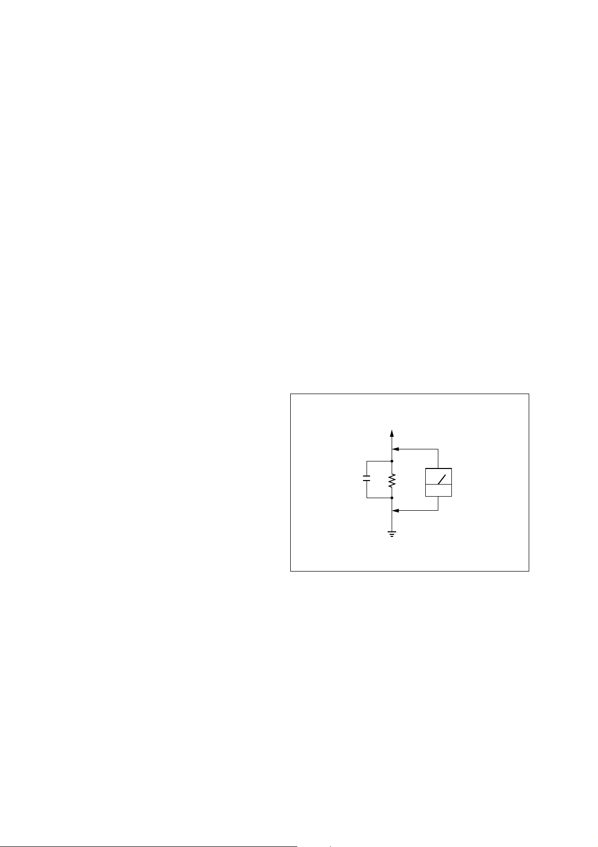
3. Measuring the voltage drop across a resistor by means of a VOM
or battery-operated AC voltmeter. The “limit” indication is 0.75
V, so analog meters must have an accurate low-voltage scale.
The Simpson 250 and Sanwa SH-63Trd are examples of a
passive VOM that is suitable. Nearly all battery operated digital
multimeters that have a 2V AC range are suitable. (See Fig. A)
To Exposed Metal
Parts on Set
Supplied accessories
Speaker cord (short) (3)
Speaker cord (long) (2)
Audio connecting cord (1)
Ta ble top stand cover (4)
Ta ble top stand base (4)
Cushion (8)
Rear pad (16)
Screw (M5) (4)
Screw (M3) (8)
Design and specifications are subject to change without notice.
0.15µF
1.5k
Ω
Earth Ground
AC
voltmeter
(0.75V)
Fig. A. Using an AC voltmeter to check AC leakage.
SAFETY-RELATED COMPONENT WARNING!!
COMPONENTS IDENTIFIED BY MARK 0 OR DOTTED LINE
WITH MARK 0 ON THE SCHEMATIC DIAGRAMS AND IN
THE PARTS LIST ARE CRITICAL TO SAFE OPERATION.
REPLACE THESE COMPONENTS WITH SONY PARTS
WHOSE PART NUMBERS APPEAR AS SHOWN IN THIS
MANUAL OR IN SUPPLEMENTS PUBLISHED BY SONY.
ATTENTION AU COMPOSANT AYANT RAPPORT
À LA SÉCURITÉ!!
LES COMPOSANTS IDENTIFIÉS PAR UNE MARQUE 0 SUR LES
DIAGRAMMES SCHÉMATIQUES ET LA LISTE DES PIÈCES SONT
CRITIQUES POUR LA SÉCURITÉ DE FONCTIONNEMENT. NE
REMPLACER CES COMPOSANTS QUE PAR DES PIÈCES SONY
DONT LES NUMÉROS SONT DONNÉS DANS CE MANUEL OU
DANS LES SUPPLÉMENTS PUBLIÉS PAR SONY.
2

SA-FT1H/WPFT1/SS-CNPFT1/MSPFT1/SRPFT1
TABLE OF CONTENTS
1. DISASSEMBLY
1-1. Back Panel Section .......................................................... 5
1-2. AMP Section ................................................................... 5
1-3. Heat Sink Section ............................................................ 6
1-4. Control/AC Board ........................................................... 6
1-5. Main Board ...................................................................... 7
2. DIAGRAMS
2-1. Block Diagram ................................................................ 9
2-2. Printed Wiring Boards –Main Section– ........................... 10
2-3. Printed Wiring Boards –Control Section– ....................... 11
2-4. Schematic Diagram –Main Section– ............................... 12
3. EXPLODED VIEWS
3-1. Subwoofer Front Section (SA-WPFT1) .......................... 13
3-2. Subwoofer AMP Section (SA-WPFT1) .......................... 14
3-3. Center Speaker Section (SS-CNPFT1) ............................ 15
3-4. Front/Surround Speaker Section
(SS-MSPFT1/SRPFT1) ................................................... 16
4. ELECTRICAL PARTS LIST .................................. 17
3

SA-FT1H/WPFT1/SS-CNPFT1/MSPFT1/SRPFT1
DISASSEMBLY
• The equipment can be removed using the following procedure.
SET
1-1. BACK PANEL SECTION
(Page 5)
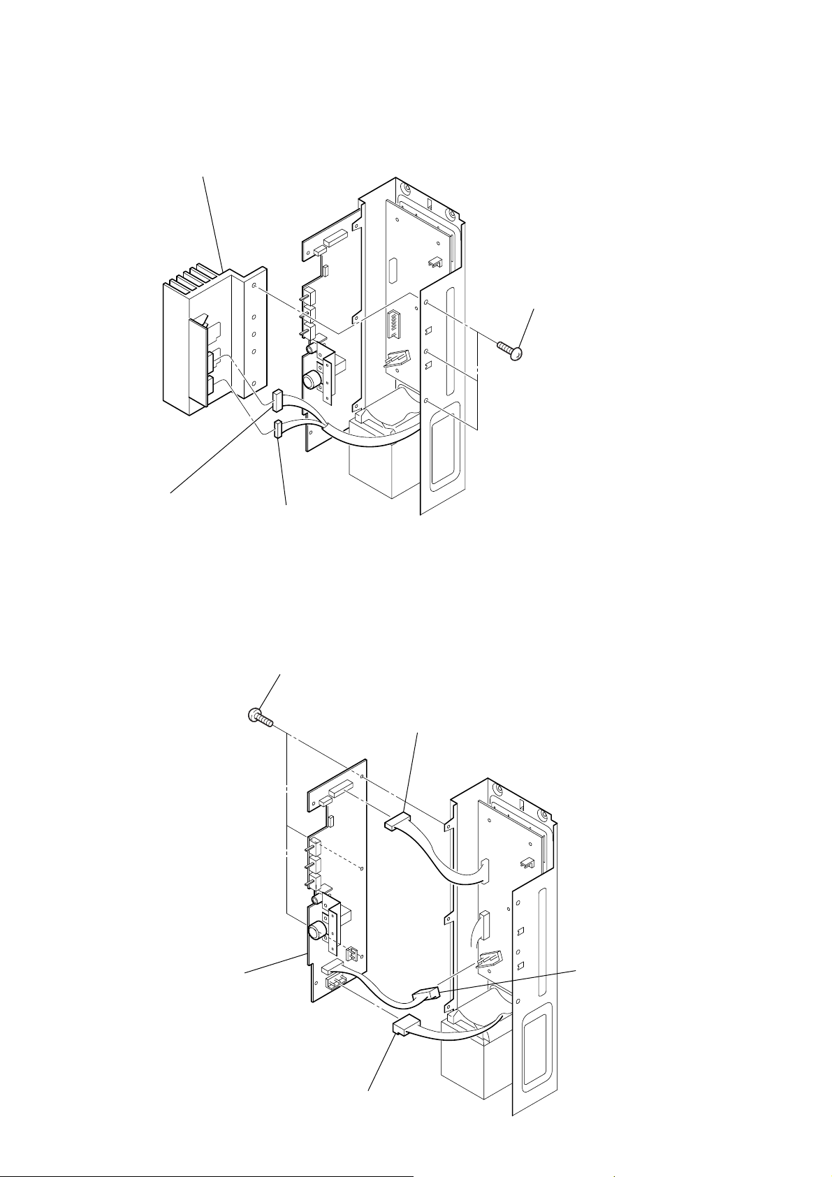
1-2. AMP SECTION
(Page 5)
SECTION 1
1-3. HEAT SINK SECTION
(Page 6)
1-5. MAIN BOARD
(Page 7)
1-4. CONTROL/AC BOARD
(Page 6)
4

Note: Follow the disassembly procedure in the numerical order given.
g
1-1. BACK PANEL SECTION
6
CNP102 (4P)
SA-FT1H/WPFT1/SS-CNPFT1/MSPFT1/SRPFT1
3
four
screws (1)
(3.5
×
16), tapping
2
three
(+BVTP 3
5
screws
1
screw
(+BVTP 3
4
four
screws (1)
(3.5
×
16), tappin
×
×
8)
8)
1-2. AMP SECTION
4
two
screws (1)
(3.5
×
16), tapping
7
AMP section
3
CN602 (3P)
7
back panel section
5
screw (1)
(3.5
×
16), tapping
6
two
(3.5
screws (1)
×
16), tapping
1
CNP901 (2P)
2
CNP501 (2P)
5
SA-FT1H/WPFT1/SS-CNPFT1/MSPFT1/SRPFT1
1-3. HEAT SINK SECTION
4
heat sink section
3
three
(+BVTT 4
screws
×
8)
2
CNP711 (5P)
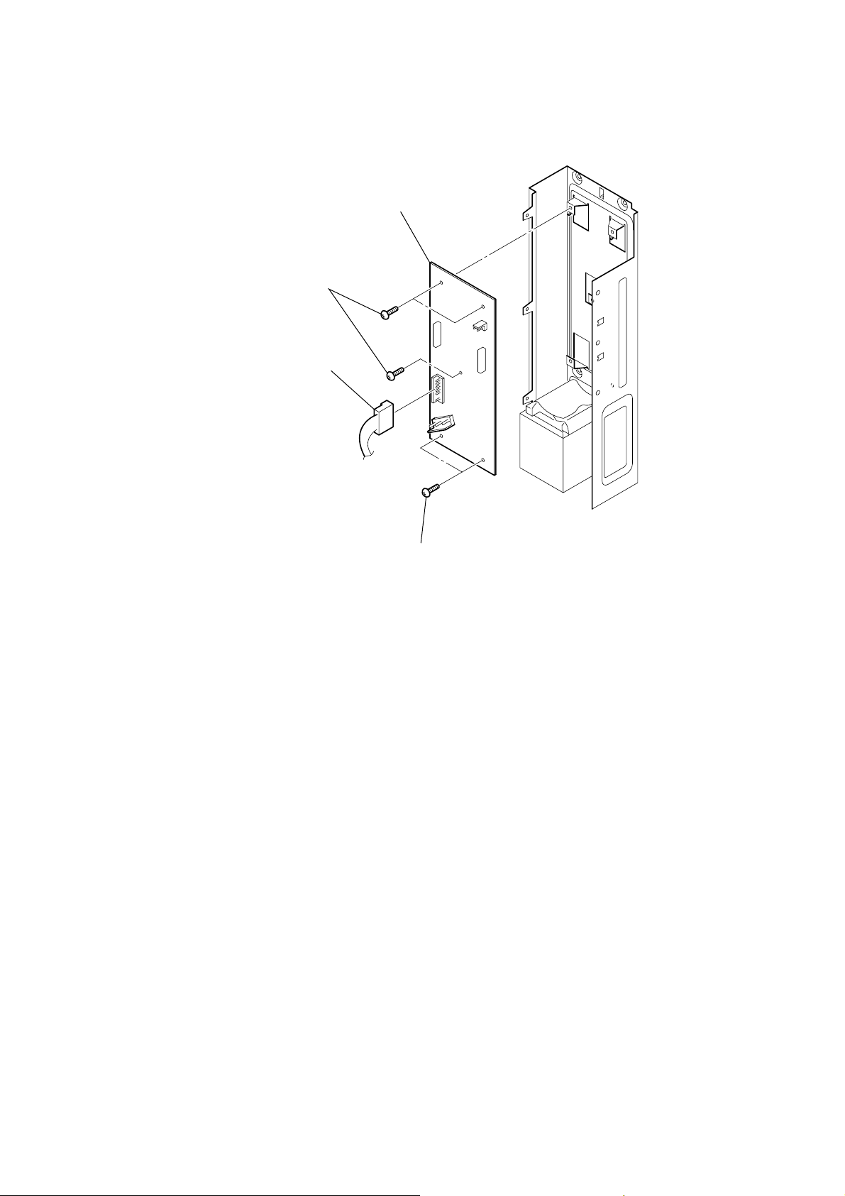
1-4. CONTROL/AC BOARD
1
CNP701 (3P)
4
three
(+BVTP 3
screws
×
8)
1
CNP103 (8P)
3
5
CONTROL/AC board
2
CNP902 (3P)
CNP904 (3P)
6
1-5. MAIN BOARD
2
three
(+BVTP 3
screws
1
CNP401 (6P)
×
SA-FT1H/WPFT1/SS-CNPFT1/MSPFT1/SRPFT1
4
MAIN board
8)
3
two
screws
(+BVTP 3
×
8)
7
 Loading...