

Page 1

Home Theater
Active Speaker System
3-759-251-22(2)
Operating Instructions
SA-\/AJ
Page 2
WARNING
To prevent fire or shock hazard, do not
expose the unit to rain or moisture.
CAUTION
RISK OF ELECTRIC SHOCK
A
CAUTION: TO REDUCE THE RISK OF ELECTRIC SHOCK.
DO NOT REMOVE COVER (OR BACK)
NO USER-SERVICEABLE PARTS INSIDE.
REFER SERVICING TO QUALIFIED SERVICE PERSONNEL.
A
DO NOT OPEN
This symbol is intended to alert the
user to the presence of uninsulated
"dangerous voltage" within the
product's enclosure that may be of
sufficient magnitude to constitute a risk
of electric shock to persons.
This symbol is intended to alert the
user to the presence of important
operating and maintenance (servicing)
instructions in the literature
accompanying the appliance.
A
INFORMATION
This equipment has been tested and found to comply with
the limits for a Class B digital device, pursuant to Part 15 of
the FCC Rules. These limits are designed to provide
reasonable protection against harmful interference in a
residential installation. This equipment generates, uses, and
can radiate radio frequency energy and, if not installed and
used in accordance with the instructions, may cause harmful
interference to radio communications. Howe\’er, there is no
guarantee that interference will not occur in a particular
installation. If this equipment does cause harmful
interference to radio or television reception, which can be
determined by turning the equipment off and on, the user is
encouraged to try to correct the interference by one or more
of the following measures:
— Reorient or relocate the receiving antenna.
— Increase the separation between the equipment and
receiver.
— Connect the equipment into an outlet on a circuit different
from that to which the receiver is connected.
— Consult the dealer or an experienced radio/TV technician
for help.
CAUTION
You are cautioned that any changes or modifications not
expressly approved in this manual could void your authority
to operate this equipment.
Owner's Record
The model and serial numbers are located on the rear of the
imit. Record the serial number in the space provided below.
Refer to them whenever you call upon your Sony dealer
regarding this product.
Model No. SA-VAl Serial No.
Page 3

Table of Contents
Precautions
Introduction
Precautions
Overview
Identifying the Parts and Controls.......................................6
Left-speaker operation panel/remote commander
Getting Started
Unpacking............................................................................7
Checking the supplied accessories
Inserting the batteries into the remote commander
Hooking Up the System.......................................................7
Positioning the speaker system
Notes on speaker connection
Connecting the speakers to video equipment.................8
Basic Operations
Enjoying Surround Sound
Adjusting the Audio...........................................................12
Advanced Operations
Enjoying Surround Sound with an External
Center Speaker...................................................................14
Four types of DOLBY PRO LOGIC modes
Speaker configurations and their respective DOLBY
PRO LOGIC modes
AddKional Information
SpeciBcations
Troubleshooting.....................................................Back cover
..........................................................................
.............................................................................
...........
.................................
.........
......................................
.........................................
.................................................
................
.....................................................
....................................................................
3
4
7
7
7
10
14
14
15
On safety
• Operate the system only on 120 V AC, 60 Hz.
• Unplug the system from the wall outlet during extended
periods of non-use. To disconnect the cord, pull it out by
6
7
grasping the plug. Never pull the cord itself.
• Should any liquid or solid object fall into either speaker,
unplug the system and have the system checked by
qualified personnel before operating it any further.
• For safety purposes, one blade of the power plug is wider
than the other to allow connection to the power outlet only
one way. If you are unable to insert the plug fully into the
outlet, contact your dealer.
Before turning on the power
Turn the speaker volume down.
To avoid damaging the speakers
• Keep the volume level to a moderate level since
excessively high sound output may damage the speakers.
• Do not attempt to open or modify the speaker units or
enclosures.
G>lor interference on nearby TVs
The speakers in this system are magnetically shielded to
minimize electrical interference to nearby TV sets.
Depending on your TV model, you may experience color
interference during operation of the speaker system. If this
happens, turn the TV off for 15 to 30 minutes, then turn it on
again. If color interference persists, move the speakers
further away from the TV set.
On instaliation
• Do not install the speakers near heat sources such as
radiators or air ducts, or in a place subject to direct
sunlight, excessive dust, mechanical vibration or shock.
• Good ventilation is essential to prevent internal heat build
up. Place the speakers at a location with adequate air
circulation, and in a way that does not block the rear
ventilation holes.
On cleaning the speaker cabinets
Clean the speaker cabinets with a soft cloth lightly
moistened with water. Do not use abrasive pads, scouring
powder or solvents such as alcohol or benzine.
For detailed safety precautions, see the leaflet entitled
"IMPORTANT SAFEGUARDS."
If you have any question or problem concerning your system
that is not covered in this manual, please consult your
nearest Sony dealer.
Page 4
Overview
The SA-VAl is a home-theater active speaker system incorporating a Dolby Pro Logic* decoder and super woofer speakers. This
all-in-one, "Tail-boy" style speaker system features a freestanding tower design styled to match your iV. Other design features
include easy connection to your video equipment and easy operation with the supplied remote commander, ensuring
maximum enjoyment of the true home theater sound this system provides.
Enhanced theater mode speaker system
The front speakers come with built-in center-channel
speakers to provide true Dolby Pro Logic surround sound
without the need for complicated s)rstem settings. This
"enhanced theater mode speaker system" provides a clear
center-signal sound image for accurate reproduction of
centrally positioned sounds such as dialogue.
Furthermore, by using the supplied rear speakers, you can
obtain full surround sound that gives you the feeling of
being in the movie itself. See "Enhanced theater mode
speaker system" on the facing page for details.
DBR (Dynamic Bass Roar) super woofer system
To provide truly dynamic bass sound for full movie
enjoyment, the SA-VAl uses SAW (Super Acousticallyloaded Woofer) type super woofers in the front speaker
system. See "SAW (Super Acoustically-loaded Woofer)" on
the facing page for details.
100-watt multi-drive amplifier system
The SA-VAl uses five ampliflers to independently drive the
super woofers, center channel tweeters, front left and right
speakers and rear speakers, achieving excellent sound
separation.
Easy connection
The SA-VAl speaker system is designed for easy
connections, including fast, one-touch connectors to connect
front speakers and simple push-terminals to connect rear
speakers with the front left speaker. You can also connect
your TV simply with an audio connecting cord.
Easy operation
The simple, logical key layout of the supplied remote
commander and the built-in operation panel on the left front
speaker result in much easier operations than conventional
AV systems.
Automatic power mode switching
Press the POWER switch and the SA-VAl enters READY
mode. In this mode, the SA-VAl turns on automatically
whenever an audio signal is input from a program source. If
the audio signal is cut off, the SA-VAl's display
automatically turns off after about 30 seconds, and after
another two and a half minutes the SA-VAl returns to
READY mode.
Three types of surround sound modes — DOLBY, HALL and SIMULATED
Enjoy any of these surround sound modes provided by the
SA-VAl (see page 10 for detaik).
Four DOLBY PRO LOGIC modes using an external
amplified center speaker
Four DOLBY PRO L(5g1C modes are available when an
amplified center speaker k connected to the left speaker's
CENTER OUT jack (see page 14).
* Manufactured under license from Dolby Laboratories
Licensing Corporation. Additionally licensed under one or
more of the following patents: U.S number 3,959,590;
Canadian numbers 1,004,603 and 1,037,877. "Dolby","Pro
Logic" and the double-D symbol □□ are trademarks of
Dolby Laboratories Licensing Corporation.
Page 5
Enhanced theater mode speaker system
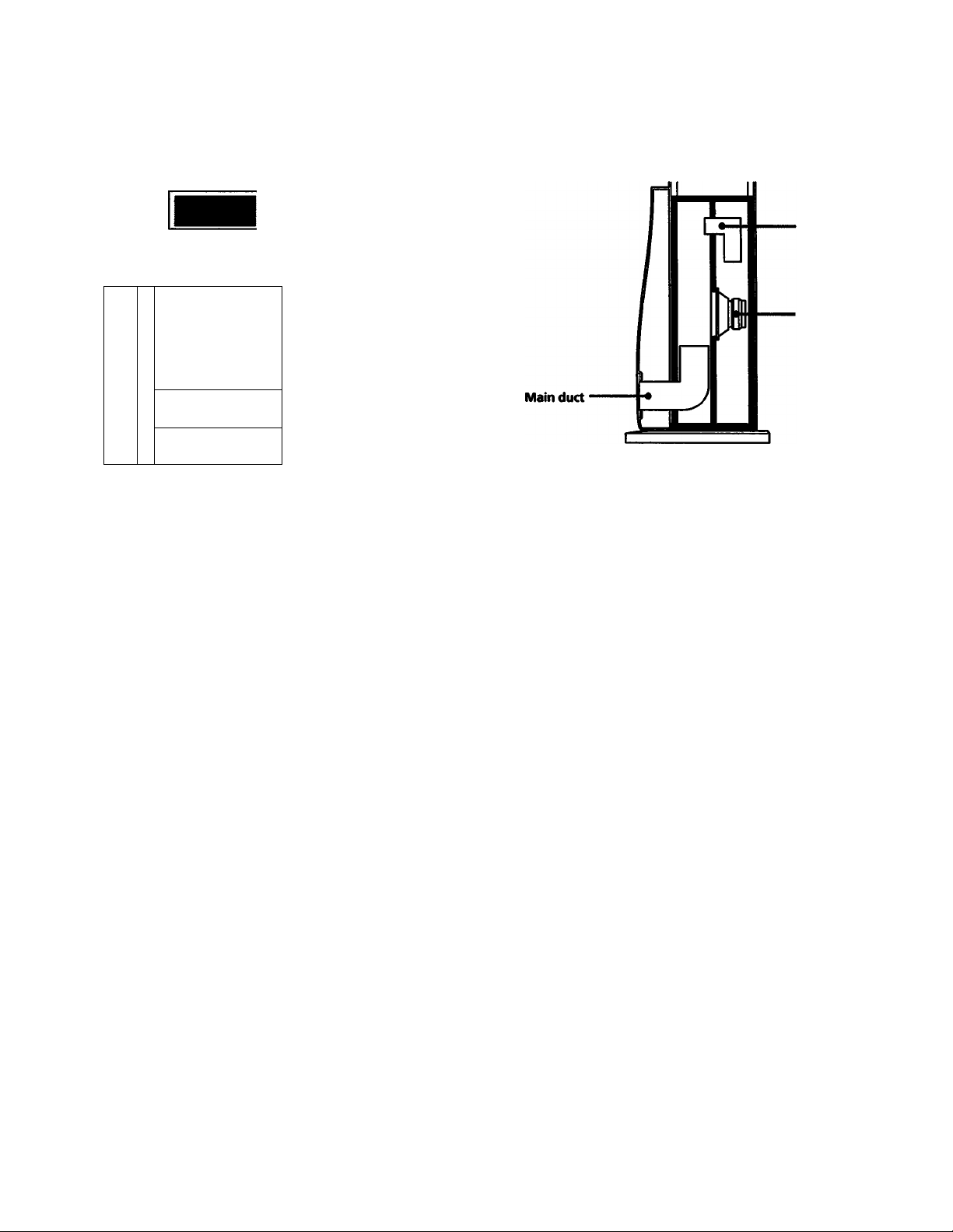
SAW (Super Acoustically-loaded Woofer)
Inner duct
□
EO
©
B
___
'M.
□
A key point in obtaining maximum surround effect when
playing sources with the Dolby Pro Logic surround sound
system is the use of a center speaker. The center speaker
makes dialogue and other centrally positioned sounds
clearer and the sound image more unified. For this reason,
true home theater systems use a center speaker equivalent in
quality to the front speakers and positioned very close to the
screen image.
With its "enhanced theater mode speaker system", the
SA-VAl offers a simple, high-performance home theater
system that produces high-quality center channel sound
with only two ftont speakers.
In this system, high-frequency center channel sound is
product by center channel tweeters, situated in the fiont
left and right speakers and oriented inwards at an angle of
30** (see diagram), and low-frequency center channel sound
is produced by mixing with front channel signak and
reproduction through the front speakers. The result k a
high-quality center sound with the same high quality as the
front channel sound, and a superior, imified sound image for
maximum surround sound effect.
.
.......... i'll
Cl
aa''
Tweeter for center
channel
-<■ Front speaker/woofer
for center channel
Super woofer
, Super woofer
drive unit
Super woofer cross section
The SA-VAl incorporates SAW-type super woofers in the
fiont left and right speakers to form a DBR super woofer
system. The SAW design features two inner chambers and a
centrally-positioned super woofer drive unit. Through
precise control of the acoustic characteristics of the front and
rear chambers, the system reproduces ultra-low firequendes
with high power and clarity.
The SA-VAl features a SAW-type super woofer in both left
and right front speakers, produdng powerful sounds for
impressive movie effects.
Page 6

Identifying the Parts and Controls
Left-speaker operation panel/remote commander
I2[3] [4l |5] [6] (71 ID
fr
For details, refer to the page numberCs) indicated in
parentheses.
[H POWER switch
[H Remote sensor
m AC STANDBY indicator
This indicator lights up when the system is connected to
an AC outlet and the system is in STANDBY mode.
S DOLBY PRO LOGIC ON/OFF button
DOLBY PRO LOGIC MODE button (pages 11 and 14)
m SURROUND button (page 11)
O Display
[3 SUPER WOOFER ON/OFF button
SUPER WOOFER MODE button (page 11)
d] STD (standard) LEVEL button (page 13)
f9l DISPLAY button (page 11)
MASTER VOL (VOLUME) +/- button(s) (pages 11
and 12)
03 MUTING button (page 11)
01 INPUT (1 /2) button(s) (page 10)
03 TEST TONE button (pages 12 and 13)
03 CENTER LEVEL +/- buttons (pages 12 and 13)
03 DELAY TIME button (page 13)
03 REAR LEVEL +/- buttons (pages 12 and 13)
03 S.WOOFER +/-buttons (page 12)
03 BASS +/- buttons (page 12)
03 TRE (treble) +/-buttons (page 12)
M BALANCE L/R buttons (page 13)
Page 7

Hooking Up the
Unpacking
Checking the supplied accessories
After unpacking, check that the following accessories are
present:
• Front L/R speaker connecting cord, 3.5 m (1)
• Rear speaker connecting cord, 10 m (2)
• Audio connecting cord, 1.5 m (1)
• Remote comnuinder RM-VAl (1)
• Sony batteries SUM-3 (NS) (2)
Inserting the batteries into the remote
commander
Before operating the remote commander, install the batteries
as shown below.
1 Open the cover.
2 Insert two size-AA (R6)
batteries with conect
polarity orientation.
System
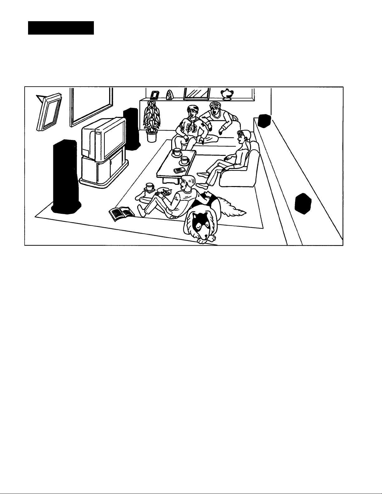
Positioning the speaker system
Location of the front speakers
To obtain high sound quality and a proper sound image
from the front speakers, place the speaker with the built-in
operation panel to the left of the TV and the other to the right
so that the center channel tweeters angle inwards toward the
center of the room.
Also, to obtain the best central sound image, we recommend
placing the left and right speakers within 2.5 meters of each
other and equidistant from the TV.
To avoid damage caused by battery leakage and corrosion
If the commander will not be used for a long time, remove
the batteries.
Battery life
About half a year of normal operation can be expected when
using Sony SUM-3 (NS), and about a year using Sony AM-3
(NW) alkaline batteries.
As the batteries run down, the remote commander will lose
its ability to control the speaker system. When this happens,
replace both batteries.
Location of the rear speakers
Place the rear speakers to the rear of your listening position
(as indicated by the shadowed area Iwlow).
Front speaker (1)
^ B ^
<S>
Rear speaker (L) Rear speaker (R)
Notes on speaker connection
• Use only the supplied speakers for the rear speaker
connection.
• Make sure to observe the terminal polarity when making
rear speaker connections. That is, connect + to + and - to -.
Connecting terminals of opposite polarity will result in
sound distortion and weakened bass.
• Since the built-in rear speaker amplifier uses the BTL
system, the - speaker cord must be firmly connected.
• Keep the TV volume turned down completely during use
Front speaker (R)
oftheSA-VAl.
Page 8

Hooking Up the System
The following two illustrations show the connectors on the rear panel of the various devices
and their respective connections.
Connecting the speakers to video equipment
Connection to TV sets with fixed>voiume audio output jacks
Front speaker (R) TV Front speaker (L)
r
FKhSPENCEh
MPUT
N
j
Rear speaker (R) Rear speaker (L)
1 Use the supplied audio connecting cord to connect INPUT 1 or 2 IN jacks on the left speaker to the AUDIO OUT jacks on the
TV.
2 Use the supplied front L/R speaker connecting cord to connect the R-ch SPEAKER OUTPUT jack of the left speaker to the
R-ch SPE/d^R INPUT jack on the right speaker.
3 Use the supplied rear speaker connecting cords to connect the rear speakers to the REAR SPEAKER terminab on the left
speaker.
4 Connect the AC power cord to a wall outlet.
Note
Make sure that the AUDIO OUT jacks on the TV are fixed-volume output jacks. If not, see "Connection to TV sete without
fixed-volume audio output jacks" described on the next page.
8
Page 9

1 Connect the INPUT 1 or 2 IN jacks on the left speaker to the AUDIO OUT jacks on the video equipment.
2 Connect the VIDEO OUT jack on the video equipment to the VIDEO IN jack on the TV.
3 Connect the INPUT 1 or 2 OUT jacks on the left speaker to the AUDIO IN jacks on the TV.
4 Use the supplied front L/R speaker connecting cord to connect the R-ch SPEAKER OUTPUT jack on the left speaker to the
R-ch SPEAKER INPUT jack on the right speaker.
5 Use the supplied rear speaker connecting cord to connect the rear speakers to the REAR SPEAKER terminals on the left
speaker.
6 Connect the AC power cord to a wall outlet.
Notes
• Make sure that the connection to either INPUT 1 or 2 jacks corresponds to the VIDEO IN jack being used on the TV set (i.e.,
VIDEO IN lor 2).
• To obtain higher quality sotmd ftx>m LD players or VCRs, we recommend that you use the procedure described in
"Connection to TV sets without fixed-volume audio output jacks" to connect the speaker system, even if your TV has
fixed-volume audio output jacks.
• Use only one pair of audio output jacks to connect your VCR or LD player, even another pair of audio output jacks is
available. Connection of both pairs of jacks at the same time will cause noise or degradation of sound quality.
Page 10

Enjoying Surround Sound
Use the procedure described below to enjoy any of the following surround sound modes:
DOLBY mode: In this mode, the built-in Dolby surround sound system produces superb
theater-like sound when playing movies or sound sources bearing the "mioiwiiii^si" or
"DOLBY STEREO" logo.
HALL mode: Select this mode to obtain dynamic surround sound effect during sports programs
broadcast in stereo.
SIMULATED mode: Select this mode to achieve simulated stereo sound from a monaural source
such as an old movie.
SUPERWOOFER
ON/OFF
Press POWER on the operation panel.
If there is no audio signal at the time you turn on
the power, the indicator on the POWER switch
lights up red and the speaker system enters
READY mode.
If there is an audio signal when you turn on the
power or an audio signal is input when the
speaker system is in READY mode, the indicator
on the POWER switch lights up green and the
speaker system begins operating immediately.
If the audio input stops, the display turns off
after about 30 seconds, and after another two and
a half minutes or so the indicator on the POWER
switch turns red and the speaker system returns
to READY mode.
Press the POWER switch again to return to
STANDBY mode.
O POWER
Operation panel
Select the program source with INPUT
(1/2).
The INPUT 1 or 2 indicator lights up.
INPUT 1
INPUT
10
INPUT 2
t>
Operation panel
Play the program source.
For details on the operation of connected
equipment, refer to the operation manual of the
respective equipment.
Remote commander
Page 11

Select the surround sound mode.
To select DOLBY mode:
Press DOLBY PRO LOGIC ON/OFF.
'TRO LOGIC" appears on the display.
•D0L8Y PRO LOGIC-
OMOPF
•PROLCK3IC-.
«0FF| I MODE I
15
Operation panel
Note
The DOLBY PRO LOGIC MODE button is
operable only when an external center speaker is
connected to the CENTER OUT jack (see page
14).
Remote commander
To change the display
Press the DISPLAY button on the operation panel.
Each press of the button changes the display as follows:
Normal display brightness
♦ ♦
Display off ♦ Dimmed
Pressing the function buttons when the display is off
momentarily causes the display to light up.
To obtain powerful bass sound
Press the SUPER WOOFER ON/OFF button.
When you press this button, the S. WOOFER indicator lights
up and powerful bass sound is output. Two super woofer
modes are provided for either movies or music. To select
either mode, press SUPER WOOFER MODE button to select
either MOVIE or MUSIC.
To select HALL or SIMULATED mode:
Press SURROUND.
Each press of the button changes the mode as
follows:
HALL ♦SIMULATED
♦ ♦
surround off
SURFIOUNO
15
Operation panel
Adjust the volume.
-O IMSTERVOL O*
if
(i"T
Operation panel
To mute the sound
Press the MUTING button.
"MUTE" appears on the display and the sound is muted.
Press the button again or press MASTER VOL + (or
VOLUME +) to turn off the muting function.
?
Remote commander
a
Remote commander
Notes
• Some commercially available software may have Dolby
surround sound tracks even though it does not carry the
mark on the package.
• Software with the "[X](^s^^"mark may have weak
rear<haimel sound output if there is a lack of rear sound
information.
11
Page 12

Adjusting the Audio
Use the audio adjustment functions described below to adjust the volume, balance and delay
time of the speaker system.
ACTIVE SP6AK6B
IS CENTER LEVEL buttons
In DOLBY or DOLBY PRO LOGIC modes (see page 14),
press CENTER LEVEL + or - to adjust the volume of the
center speaker over a range of +10 dB to -10 dB, in 1 dB
steps.
Œ3
CENTER
LEVEL
CZ3
Remote commander
(1 REAR LEVEL +/- buttons
In DOLBY or DOLBY PRO LOGIC modes, press REAR
LEVEL+ or - to adjust the volume of the rear speakers
over a range of+10 dB to -10 dB, in 1 dB steps.
REAR
LEVEL
ŒD
Remote commander
IS S.WOOFER +/- buttons
When the super woofer speakers are active (see page 11),
press S. WOOFER + or - to adjust the volume of the super
woofers over a range of +10 dB to -10 dB, in 2 dB steps.
|D| BASS +/- and TRE *1- buttons
Press BASS + or TRE + to increase the bass or treble of
the front and center speakers, and BASS - or TRE - to
reduce the bass or treble of the same speakers over a
range of +10 dB to -10 dB, in 2 dB steps.
m CEi
BASS TRE
CZD (ZD
Remote commander
H TEST TONE button
In DOLBY or DOLBY PRO IXXjIC modes, pressing the
TEST TONE button causes a test tone signal to be
sequentially output from each speaker, allowing you to
adjust the sound level of each speaker to achieve a
balanced sound image.
1 Press MASTER VOL (VOLUME)+/-to select the
sound volume that you commonly use.
Q
-O MASTERVOl O*
VOLUME
Q
Operation panel Remote commander
12
LU
SWOOFER
ŒÎ
Remote commander
Page 13

2 Press TEST TONE.
A test tone is output automatically from each speaker
in the following order
Front (L) ♦ Center (C)
♦ ♦
Rear ♦ Front (R)
TEST TONE
im
Remote commander
Adjust the sound level of the center and rear speakers
and the balance of the sound from the front speakers
with CENTER LEVEL +/- REAR LEVEL +/- and
BALANCE L/R to obtain the same sound level from
each speaker in respect to your listening position.
The volume of the center and rear speakers appears
on the display, and is adjusted in a range of -t-lO dB to
-10 dB, in 1 dB steps.
I DELAY TIME button
The DELAY TIME button allows you to change the
spatial characteristics of the sound in DOLBY or DOLBY
PRO LOGIC modes.
Press DELAY TIME to choose one of the following delay
times:15,20,25, and 30 ms. The selected delay time
appears on the display.
DELAY TIME
CD
Remote commander
[H] STD LEVEL button
Press STD LEVEL to restore the volume level of the
center, rear, super woofer speakers and delay time to
their factory settings (the STD LEVEL indicator lights
up), and again to restore the previous volume level of
each speaker and delay time.
If the super woofers are off, pressing the STD LEVEL
button causes the super woofer speakers to turn on
automatically.
CENTER
LEVEL
Œ]
REAR
LEVEL
Remote commander
- BALANCE -
4 Press TEST TONE to turn off the test tone signal.
TESTTONE
CD
m BALANCE L/R buttons
Use the BALANCE L/R buttons to obtain symmetry in
the sound image.
Press BALANCE L to move the sound image leftward.
Press BALANCE R to move the sound image rightward.
■- BALANCE ->
QD CD
Remote commander
Note
Since the BALANCE L/R buttons control sound from the
front right and left speakers, they have little effect in the
DOLBY PRO LOGIC modes (see page 14) for sources
with a high proportion of center-channel components.
Operation panel
STD LEVEL
(CD
Remote commander
13
Page 14

Enjoying Surround Sound with an External
Center Speaker
Four types of DOLBY PRO LOGIC modes
You can specify four different IXDLBY PRO LOGIC inodes
when the CENTER OUT jack on the left speaker is connected
to an external center speaker with a built-in amplifier or
through an independent amplifier.
Be sure to set the volume of the external center speaker to the
minimum before you connect it to the CENTER OUT jack, or
before you connect/disconnect the AC power cord of the
front left speaker to prevent unexpected noise.
Speaker configurations and their respective
DOLBY PRO LOGIC modes
NORMAL mode
Select this mode when using a small center speaker (e.g.,
your TV's internal speaker). The front speakers output the
bass sound of the center channel since the small speaker
produces insufficient bass.
WIDE mode
Select this mode when using a medium to large center
speaker.
Center speaker
Front speaker (L) | Front speaker (R):er (L) I From
Q® 0
<S> ^
Rear speaker (L) (3' Rear speaker (R)
NORMAL/WIDE____________________
PHANTOM mode
Select this mode when not using a center speaker. The front
speakers output the sound of the center channel.
Press DOLBY PRO LOGIC ON/OFF to activate a connected
external center speaker, then DOLBY PRO LOGIC MODE to
select the mode corresponding to yoim speaker
configuration.
-OOISV POO LOGIC -
Operation panel
■-PRO LOGIC-»
|OWOFF| I MODE I
Remote commander
Each press of the DOLBY PRO LOGIC MODE button
changes the mode as follows:
NORMAL
e
3CH LOGIC
Notes
WIDE
♦
PHANTOM
• The DOLBY PRO LOGIC MODE button is operable only
when an external center speaker is connected to the
CENTER OUT jack.
• When an external center speaker is not connected, you
may still enjoy surroimd sound through the surround
sound modes (see page 10) available through SA-VAl's
"enhanced theater mode speaker system".
Front speaker (L)
______
Front speaker (R)
Q® 0
<M>
Rear speaker (L) (3 O Rear speaker (R)
PHANTOM
3CH (channel) LOGIC mode
Select this mode when using only the front and center
speakers.
lite front speakers output the sound of the rear channel,
center speaker
Front speaker (L) | Front speaker (R)t(L) { Front
Q® 0
cS>
3CH LOGIC
14
Page 15

Specifications
AUDIO POWER SPECIFICATIONS
POWER OUTPUT AND TOTAL HARMONIC
DISTORTION:
For front full range/center woofer
speakers: with 4 ohm loads, both
channels driven, from 40 Hz -20 kHz:
rated 18 watts per channel minimum
RMS power, with no more than 0.8 %
total harmonic distortion from 250
milliwatts to rated output.
other specifications
Amplifier section
Continuous RMS power output
total 100 W
Center tweeter; 17 W (4 ohms at
10kHz,10%THD)
Front full range/center woofer :22 W +
22W
(4 ohms at 1 kHz, 10% THD)
Super woofer: 22 W (4 ohms at 40 Hz,
10% THD)
Rear 17 W (4 ohms at 1 kHz, 10%
THD)
Input sensitivity/impedance
INPUT 1 /2:450 mV, 50 kD
Output
INPUT 1/2:450 mV, lk£2
Center; 650 mV, 2 kil
Rear: Accept only supplied rear
speakers SS-SRll
R-ch: Accept only SA-VAl R-ch
speaker with supplied front L/R
speaker connecting cord
Speaker section
Type
Front speaker system
Bassreflex type
DBR super woofer SAW type
Rear speaker Bassreflex type
Speaker unit
Front speaker system
Center tweeter: 5 cm cone type (x2)
Front full range/center woofer: 10 cm
cone type (>^)
Super woofer 13 cm cone type (x2)
Rear speaker 8 cm cone type (x2)
General
Power requirement 120 V AC, 60 Hz
Power consumption 60 W
Dimensions Approx. 180 x 1040 x 305 mm (w/h/d)
(7'/«X 41 X12 inches)
Approx. 240 X1040 x 370 mm (w/h/d,
including speaker base)
(9 '/2 X 41 X14 */s inches)
Mass Front (L): 16 kg (35 lb 3 oz)
Front (R): 13 kg (28 lb 9 oz)
Rear: 800 g/pc (1 lb 12 oz)
Supplied accessories
Front L/R speaker connecting cord,
3.5 m(l)
Rear speaker connecting cord, 10 m (2)
Audio connecting cord, 1.5 m (1)
Remote commander RM-VAl (1)
Sony batteries SUM-3 (NS) (2)
E)esign and specihcations are subject to change without
notice.
Tone control
Front/center
Super woofer
Bass; ±10 dB at 100 Hz
Treble: ±10 dB at 10 kHz
+10 dB at 30 Hz in MOVIE mode
Page 16

Troubleshooting
Before proceeding through the check list below, flrst refer back to the connection and operating procedures. Should any
problem persist after you have made these checks, consult your nearest Sony dealer.
Trouble
No sound is heard from any speakers.
Sound is heard only from the external
center speaker in (DOLBY PRO •
LOGIC) NORMAL, WIDE or 3CH
LCX3IC mode.
No sound is heard from the center
speaker.
No sound or very low level sound is
heard from the rear speakers.
Cause
The speaker terminals are shortcircuited.
You pressed the MUTING button. Press MUTING to cancel the muting
A monaural program source is being
played.
(DOLBY PRO LOGIC) PHANTOM
mode is selected or no center speaker
is connected.
The volume of the center speaker is
very low.
HALL or SIMULATED mode is
selected.
The DOLBY PRO LOGIC ON/OFF
button is turned off.
Check the speaker connections.
function (see page 11).
Turn off DOLBY PRO LOGIC ON/
OFF to cancel the DOLBY PRO LOGIC
modes, or select SIMULATED mode
(see page 11).
No sound is output from the external
center speaker in PHANTOM mode.
Select another mode (see page 14).
Adjust the volume of the center
speaker with CENTER LEVEL +/-
(see page 12).
Sound from the center speaker is
inaudible in these modes.
Turn on DOLBY PRO LOGIC ON/
OFF (see pages 11 and 14).
Solution
(DOLBY PRO LOGIC) 3CH LOGIC
mode is selected.
The volume of the rear speakers is
very low.
A program source with little surround
sound effect is being played.
Severe hum or noise is heard.
Remote commander operations cannot
be performed.
If normal operation does not resume after attempting the prescribed remedy, turn off the power and remsert the plug into the
power outlet.
The connecting cords are picking up
interference from a transformer, motor
or fluorescent light.
The batteries are run down. Replace the batteries.
The emitter on the remote commander
is not pointed at the remote sensor on
the operation panel.
There is an obstruction between the
remote commander and the SA-VAl.
Soimd is not output from the rear
speakers in 3CH LCX^IC mode.
Select another mode (see page 14).
Adjust the volume of the rear speakers
with REAR LEVEL +/- (see page 12).
Check the sound image balance with
TEST TONE (see pages 12 and 13).
Move the connecting cords away from
the transformer or motor, or at least 3
meters (10 feet) from the fluorescent
light.
Point the remote commander's emitter
towards the remote sensor.
Remove the obstruction.
Sony Corporation Printed in Japan
 Loading...