

Sony SAL1870 Service Manual
SAL1870
(See Page 3-2.)
12
17
13
(3.5-5.6/18-70) (DT 18-70mm F3.5-5.6)
US Model
SERVICE MANUAL
Ver. 1.3 2007.08
Canadian Model
Chinese Model
SUPPLEMENT-1
File this supplement with the service manual.
(DI07-053)
• Addition of Repair Parts
• Correction of error in writing
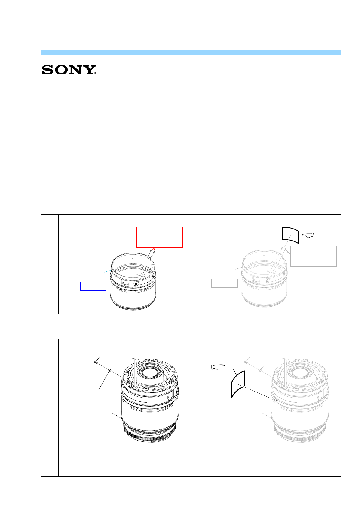
2-1-2. GEAR BARREL, ZOOM CAM BARREL AND ZOOM CONTROL TUBE BLOCK
& : Points added portion.
Page
2-3
0 Zoom
Barrel
HELP05
Before change After change
FOCUS-SHIFT
/FLANGE BACK
ADJUSTMENT
0 Zoom
Barrel
HELP05
AEP Model
FOCUS-SHIFT
/FLANGE BACK
ADJUSTMENT
3-1-1. LENS MOUNT BLOCK AND ZOOM RETAINER TUBE BLOCK
Page Before change After change
12
13
3-1
SAL1870 (3.5-5.6/18-70) (DT 18-70mm F3.5-5.6)
Ref. No. Part No. Description
9-876-947-82
(See Page 3-2.)
—— ————— ————————
Ref. No. Part No. Description
17 2-898-231-01 COVER, ZOOM ADJUSTMENT HOLE
Sony EMCS Co.
& : Points added portion.
)
2007H0800-1
© 2007. 08
Published by Kohda TEC
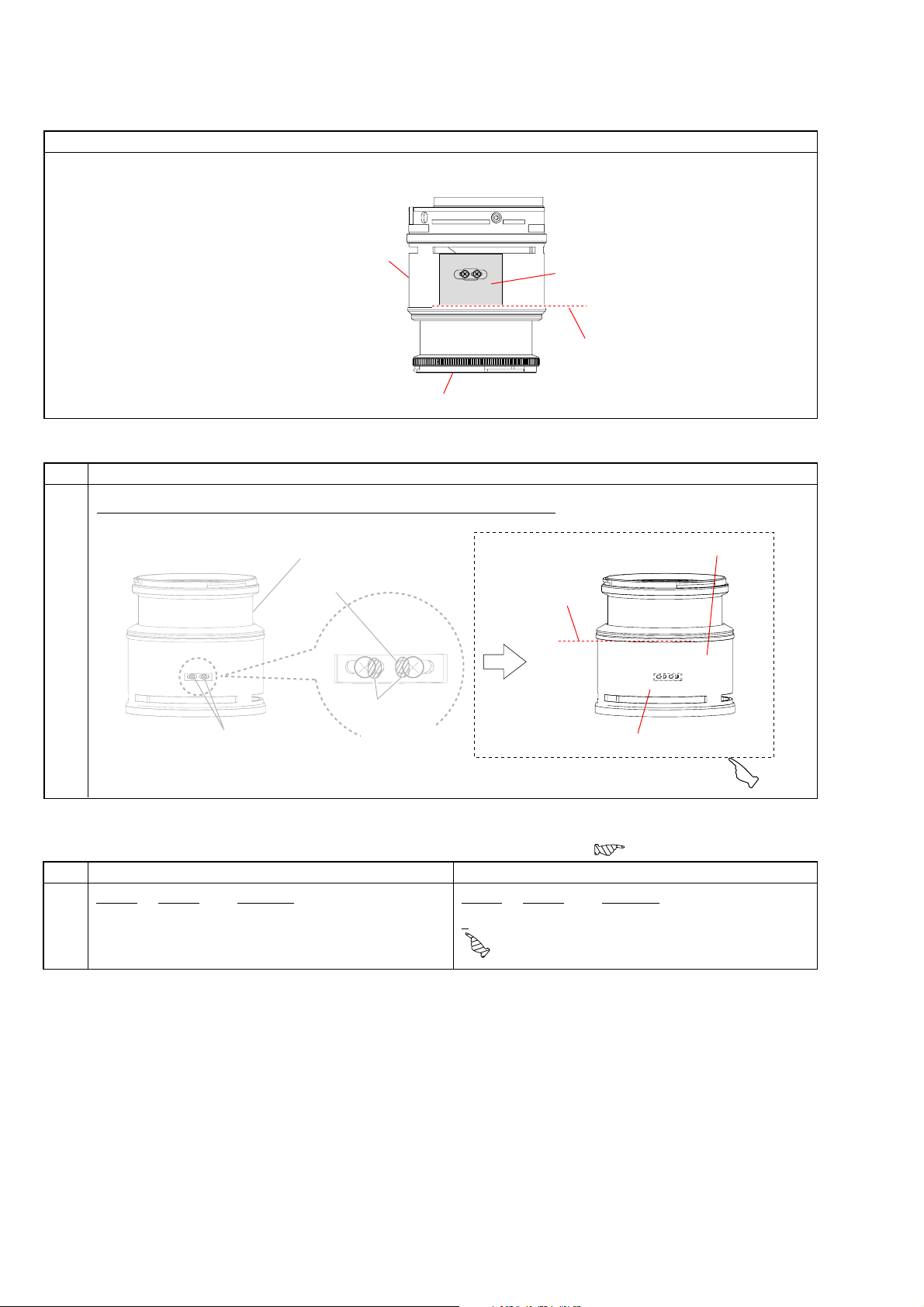
HELP07
Zoom Barrel
Zoom Adjustment
Hole Cover
Reference Line
Front Lens Barrel
Added contents
9. Attach the zoom adjustment hole cover to the zoom barrel as shown in figure.
4-4-2. Focus-shift/Flange Back (f’F) Adjustment
Page
12) Attach the zoom adjustment hole cover to the zoom barrel as shown in figure.
Focus Ring
Focus Stopper
4-15
Two screws
• Correction of error in writing
Added contents
Apply the
adhesive
bond (B-10)
3-1-3. ZOOM CONTROL TUBE BLOCK
Page
3-3
Ref. No. Part No. Description
107 9-913-210-00 POLYESTER TAPE (Note 1)
Incorrect Correct
& : Points added portion.
*
Front Lens Barrel
Reference Line
Zoom Adjustment Hole Cover
: Points changed portion.
Ref. No. Part No. Description
* 107 9-913-210-00 POLYESTER TAPE (Note 1)
SAL1870 (3.5-5.6/18-70) (DT 18-70mm F3.5-5.6)
— 2 —
 Loading...