

(3.5-5.6/18-70) (DT 18-70mm F3.5-5.6)
SERVICE MANUAL
SAL1870
Ver. 1.5 2008.04
Revision History
Revision History
How to use
How to use
Acrobat Reader
Acrobat Reader
Revised-2
Replace the previously issued
SERVICE MANUAL 9-876-947-12
with this Manual.
Link
Link
SPECIFICATIONS
US Model
Canadian Model
AEP Model
Chinese Model
DISASSEMBLY ADJUSTMENTS
SERVICE NOTE
• About the Lens Test Projector
REPAIR PARTS LIST
LENS FOR DSLR CAMERA
SAL1870 (3.5-5.6/18-70) (DT 18-70mm F3.5-5.6)
Sony EMCS Co.
2008D0800-1
© 2008.04
Published by Kohda TEC9-876-947-13

SPECIFICATIONS
• This lens is equipped with a distance encoder. The distance encoder allows more accurate measurement (ADI) by using a flash for ADI.
• Depending on the lens mechanism, the focal length may change with any change of the shooting distance. The focal length assumes the lens is focused
at infinity.
Equivalent 35mm-format focal length *1 (mm)
27-105
Lens groups elements
9-11
Angle of view *
76°-23°
*1The values for equivalent 35mm-format focal length and angle of view are based on Digital Single Lens Reflex Cameras equipped with an APS-
C sized image sensor.
Minimum focus *2 (m (feet))
0.38 (1.2)
*2Minimum focus is the shortest distance from the image sensor to the subject.
Maximum magnification (X)
0.25
Minimum f-stop
f/22-36
Filter diameter (mm)
55
Dimensions (maximum diameter
Approx. 66 × 77 (2 5/8 × 3 1/8)
Mass (g (oz.))
Approx. 235 (8 5/16)
Included items
Lens (1), Front lens cap (1), Rear lens cap (1), Lens hood (1), Set of printed documentation
Designs and specifications are subject to change without notice.
1
××
× height) (mm (in.))
××
SAL1870 (3.5-5.6/18-70) (DT 18-70mm F3.5-5.6)
— 2 —

TABLE OF CONTENTS
Section Title Page
1. SERVICE NOTE
1-1. Chemicals ·······································································1-1
1-2. Exterior Parts··································································1-1
1-3. Unleaded Solder ·····························································1-1
1-4. Safty Check-out······························································1-2
1-5. Troubleshooting ·····························································1-3
2. DISASSEMBLY
2-1. Disassembly ···································································2-2
3. REPAIR PARTS LIST
3-1. Exploded Vie ws······························································3-1
3-2. Supplied Accessories······················································3-6
4. ADJUSTMENTS
4-1. Preparations····································································4-1
4-2. Aperture Diameter Check/Adjustment···························4-4
4-3. Projective Resolving Power Check ································4-9
4-4. Focus-shift/Flange Back (f’F) Check/Adjustment ·······4-12
4-5. Lens ROM Check·························································4-16
4-6. Zoom Brush Position Check/Adjustment and
Pattern Check ·······························································4-17
4-7. Focus Brush Position Check/Adjustment and
Pattern Check ·······························································4-20
4-8. Error Code List·····························································4-23
SAL1870 (3.5-5.6/18-70) (DT 18-70mm F3.5-5.6)
— 3 —

1. SERVICE NOTE
1-1. Chemicals
Some chemicals used for servicing are highly volatile.
Their evaporation caused by improper management affects your health and environment, and wastes resources.
Manage the chemicals carefully as follows.
• Store chemicals sealed in a specific place to prevent from exposure to high temperature or direct sunlight.
• Avoid dividing chemicals into excessive numbers of small containers to reduce natural evaporation.
• Keep containers sealed to avoid natural evaporation when chemicals are not in use.
• Avoid using chemicals as much as possible. When using chemicals, divide only required amount to a small plate from the container and
use up it.
1-2. Exterior Parts
Be careful to the following points for exterior parts used in this unit.
• Use a piece of cleaning paper or cleaning cloth for cleaning exterior parts. Avoid using chemicals.
Even if you have to use chemicals to clean heavy dirt, don’t use paint thinner, ketone, nor alcohol.
• Insert the specific screws vertically to the part when installing a exterior part.
Be careful not to tighten screws too much.
1-3. Unleaded Solder
This unit uses unleaded solder.
Boards requiring use of unleaded solder are printed with the lead free mark (LF) indicating the solder contains no lead.
(
Caution: Some printed circuit boards may not come printed with the lead free mark due to their particular size.)
: LEAD FREE MARK
Be careful to the following points to solder or unsolder.
• Set the soldering iron tip temperature to 350 °C approximately.
If cannot control temperature, solder/unsolder at high temperature for a short time.
Caution: The printed pattern (copper foil) may peel away if the heated tip is applied for too long, so be careful!
Unleaded solder is more viscous (sticky, less prone to flow) than ordinary solder so use caution not to let solder bridges
occur such as on IC pins, etc.
• Be sure to control soldering iron tips used for unleaded solder and those for leaded solder so they are managed separately. Mixing
unleaded solder and leaded solder will cause detachment phenomenon.
SAL1870 (3.5-5.6/18-70) (DT 18-70mm F3.5-5.6)
1-1

1-4. SAFETY CHECK-OUT
After correcting the original service problem, perform the following safety checks before releasing the set to the customer.
1. Check the area of your repair for unsoldered or poorly-soldered connections. Check the entire board surface for solder splashes and
bridges.
2. Check the interboard wiring to ensure that no wires are “pinched” or contact high-wattage resistors.
3. Look for unauthorized replacement parts, particularly transistors, that were installed during a previous repair. Point them out to the
customer and recommend their replacement.
4. Look for parts which, through functioning, show obvious signs of deterioration. Point them out to the customer and recommend their
replacement.
5. Check the B+ voltage to see it is at the values specified.
6. Flexible Circuit Board Repairing
• Keep the temperature of the soldering iron around 270 °C during repairing.
• Do not touch the soldering iron on the same conductor of the circuit board (within 3 times).
• Be careful not to apply force on the conductor when soldering or unsoldering.
Danger of explosion if battery is incorrectly replaced.
CAUTION
Replace only with the same or equivalent type.
SAFETY-RELATED COMPONENT WARNING!!
COMPONENTS IDENTIFIED BY MARK 0 OR DOTTED LINE WITH
MARK 0 ON THE SCHEMATIC DIAGRAMS AND IN THE PARTS
LIST ARE CRITICAL TO SAFE OPERATION. REPLACE THESE
COMPONENTS WITH SONY PARTS WHOSE PART NUMBERS
APPEAR AS SHOWN IN THIS MANUAL OR IN SUPPLEMENTS
PUBLISHED BY SONY.
ATTENTION AU COMPOSANT AYANT RAPPORT
À LA SÉCURITÉ!
LES COMPOSANTS IDENTIFÉS P AR UNE MARQUE 0 SUR LES
DIAGRAMMES SCHÉMA TIQUES ET LA LISTE DES PIÈCES SONT
CRITIQUES POUR LA SÉCURITÉ DE FONCTIONNEMENT. NE
REMPLACER CES COMPOSANTS QUE PAR DES PIÈSES SONY
DONT LES NUMÉROS SONT DONNÉS DANS CE MANUEL OU
DANS LES SUPPÉMENTS PUBLIÉS PAR SONY.
SAL1870 (3.5-5.6/18-70) (DT 18-70mm F3.5-5.6)
1-2
Ver 1.1 2007.02
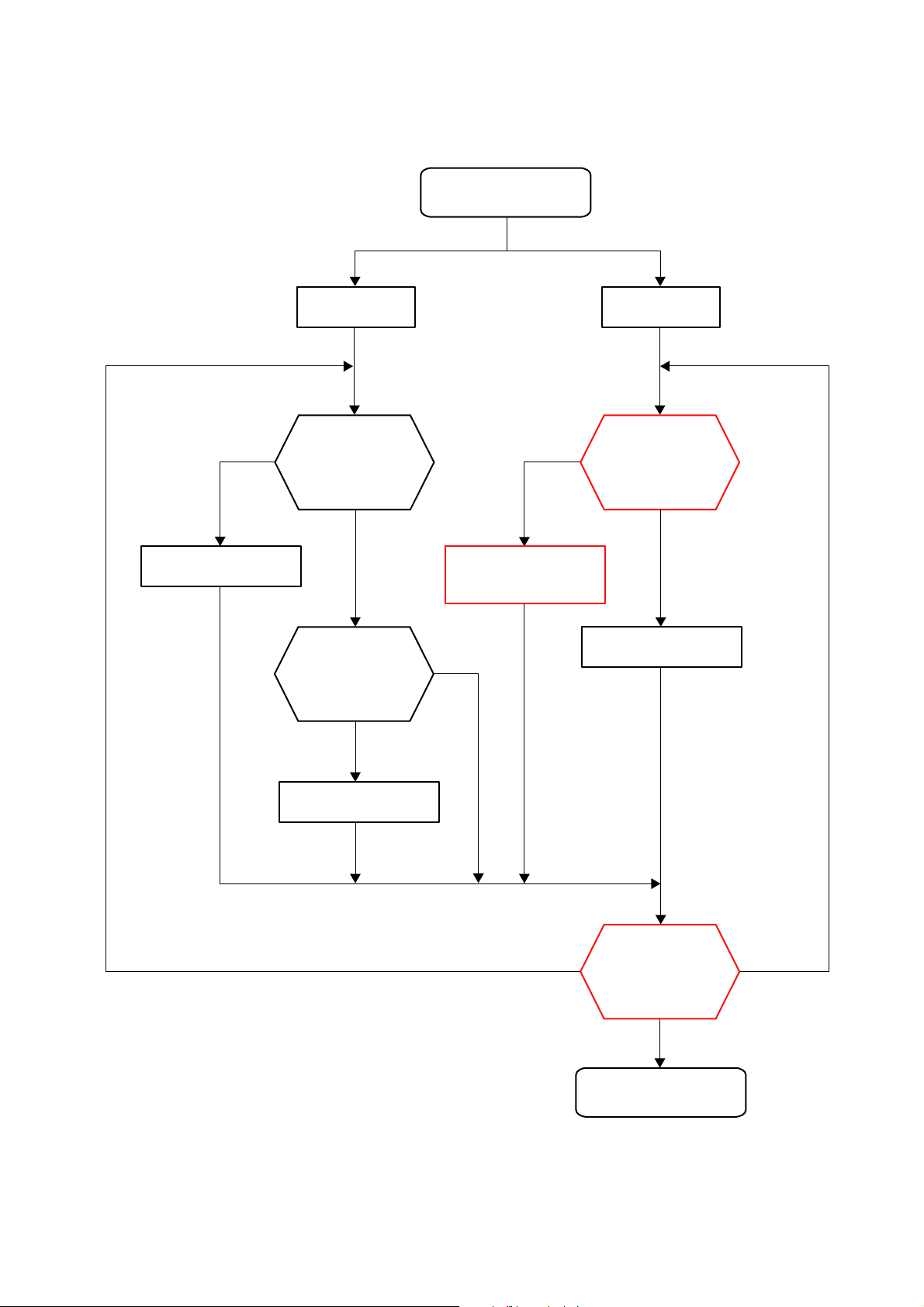
1-5. TROUBLESHOOTING
1-5-1. Aperture Trouble
Aperture trouble
Function NG F No. NG
NG
Replace the lens
mount block.
Check operation of
the preset ring.
OK
Check operation
of the rear lens
group block.
NG
Replace the rear lens
group block.
Perform the aperture
diameter adjustment.
(See page 4-7.)
OK
Perform the aperture
NG
diameter check.
(See page 4-4.)
Replace the lens
OK
mount block.
SAL1870 (3.5-5.6/18-70) (DT 18-70mm F3.5-5.6)
1-3
Perform the aperture
diameter check.
(See page 4-4.)
OK
END
NGNG
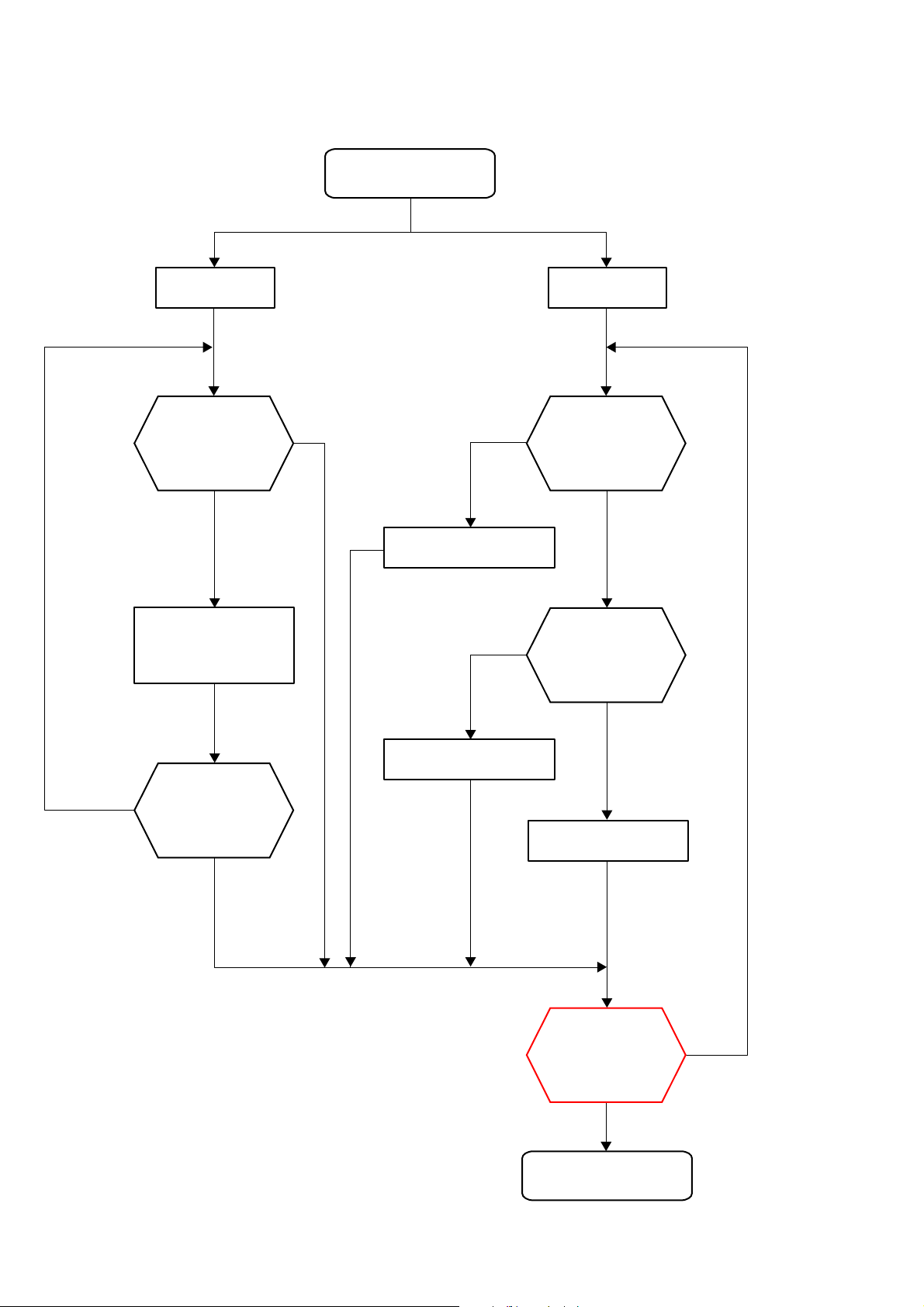
1-5-2. Zoom T rouble
Function NG Position NG
Zoom trouble
Disassembly and check
the zoom relation parts.
Replace the defective part
or apply the grease.
NG
Check the operation
again.
NG
OK
OK
NG
Adjust the position, or
replace the zoom brush.
NG
Clean the pattern of the
zoom flexible.
Check the position
and deformation
at the tip of
the zoom brush.
OK
Check pattern
of the zoom flexible.
OK
Replace the main
flexible block.
SAL1870 (3.5-5.6/18-70) (DT 18-70mm F3.5-5.6)
1-4
Perform the
zoom brush position
check/adjustment.
(See page 4-17.)
OK
END
NG

1-5-3. Focus T rouble
Focus trouble
Function NG Position NG
Replace the defective part
or apply the grease.
Check the
AF coupler and
coupler gear.
OK
Check the
gear barrel.
NG
Replace the defective part
or apply the grease.
OK
NGNG
Adjust the position, or
replace the focus brush.
NG
Clean the pattern of the
focus flexible.
Check the position
and deformation
at the tip of
the focus brush.
OK
Check pattern
of the focus flexible.
OK
NG
Check the operation
again.
OK
SAL1870 (3.5-5.6/18-70) (DT 18-70mm F3.5-5.6)
1-5
Replace the main
flexible block.
Perform the
focus brush position
check/adjustment.
(See page 4-20.)
OK
END
NG
Ver 1.1 2007.02
NOTE FOR REPAIR
2. DISASSEMBLY
• Make sure that the flat cable and flexible board are not cracked of bent at the terminal.
Do not insert the cable insufficiently nor crookedly.
• When remove a connector, dont’ pull at wire of connector. It is possible that a wire is snapped.
• When installing a connector, dont’ press down at wire of connector.
It is possible that a wire is snapped.
• Do not apply excessive load to the gilded flexible board.
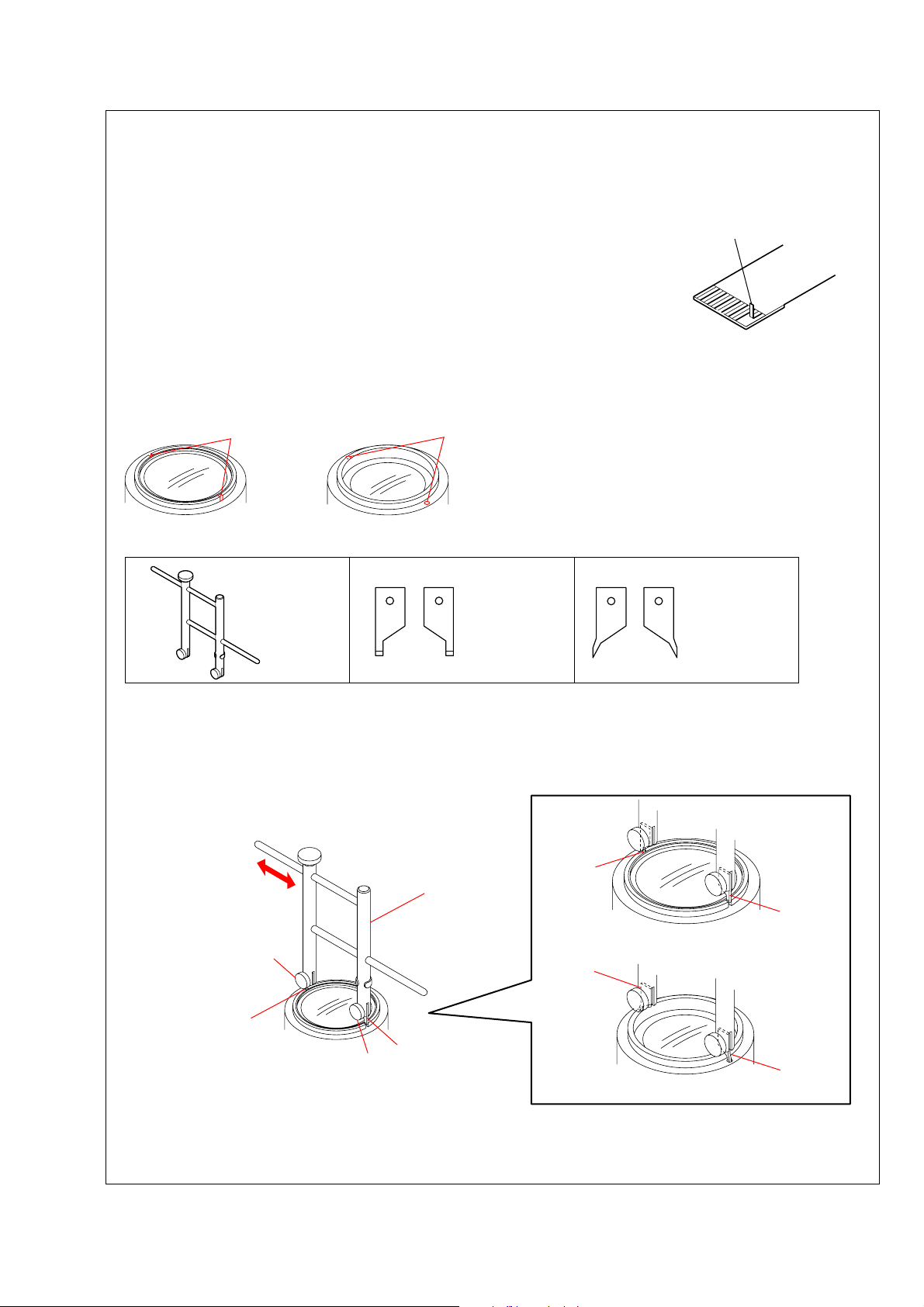
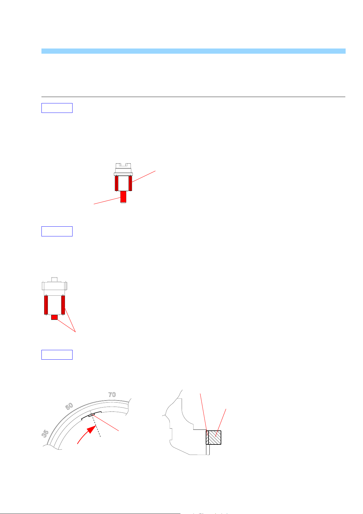
UNIVERSAL WRENCH
In case of the following notches or holes are located in the lens block, etc during disassembling/
assembling the lens, Use the universal wrench.
Notches Holes
How to Use
Universal wrench
J-6082-609-A
Chip-A for
universal wrench:
J-6082-609-1
Cut and remove the part of gilt
which comes off at the point.
(Be careful or some
pieces of gilt may be left inside)
Chip-B for
universal wrench:
J-6082-609-2
Attach the chip-A or chip-B to the universal wrench.
For the notches: chip-A
For the holes: chip-B
Match the universal wrench to the holes or notches of the lens block, etc.
Chip-A
Match the universal wrench
to the width of holes or notches.
Fixed screw
Chip
Fixed screw
When top of tip does not reach holes or notches because the fixed screw becomes obstructive,
replace the fixed screw to below.
+B 3X5 7-682-546-09
Universal wrench
Chip-B
Chip
Chip-A
Notches
Chip-B
Holes
SAL1870 (3.5-5.6/18-70) (DT 18-70mm F3.5-5.6)
2-1
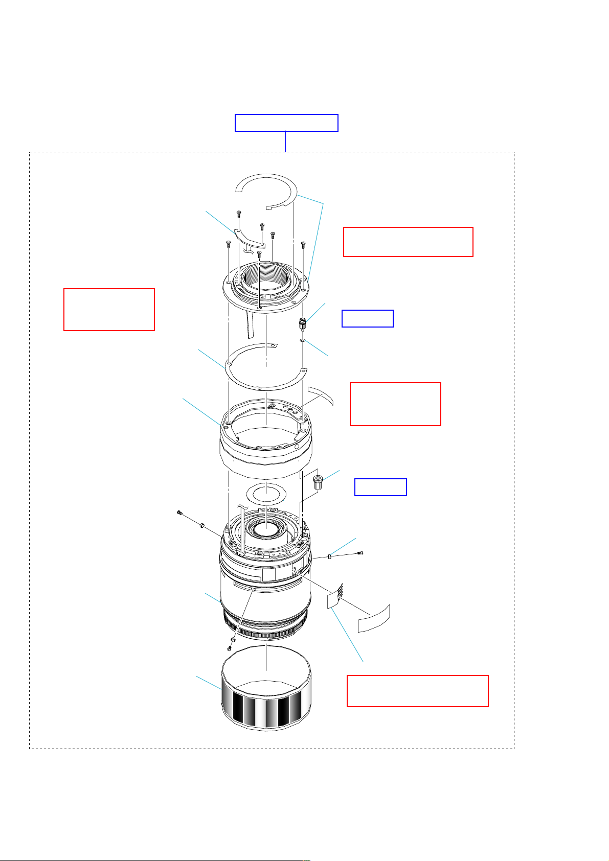
2-1. DISASSEMBLY
2-1-1. LENS MOUNT BLOCK AND ZOOM RETAINER TUBE BLOCK
EXPLODED VIEW
1 Main Flexible Block
FOCUS-SHIFT/
FLANGE BACK
ADJUSTMENT
3 Back Adjustment Washer
5 Zoom Retainer Tube
Block
2 Mount Decoration Plate
and Lens Mount Block
APERTURE DIAMETER
ADJUSTMENT
4 AF Coupler
HELP01
4 Coupler Adjustment
Washer
FOCUS-SHIFT/
FLANGE BACK
ADJUSTMENT
6 Coupler Gear
HELP02
(See Page 2-3.)
8 Zoom Rubber Ring
SAL1870 (3.5-5.6/18-70) (DT 18-70mm F3.5-5.6)
9 Zoom Guide Roller
7 Brush
ZOOM BRUSH POSITION
ADJUSTMENT
2-2
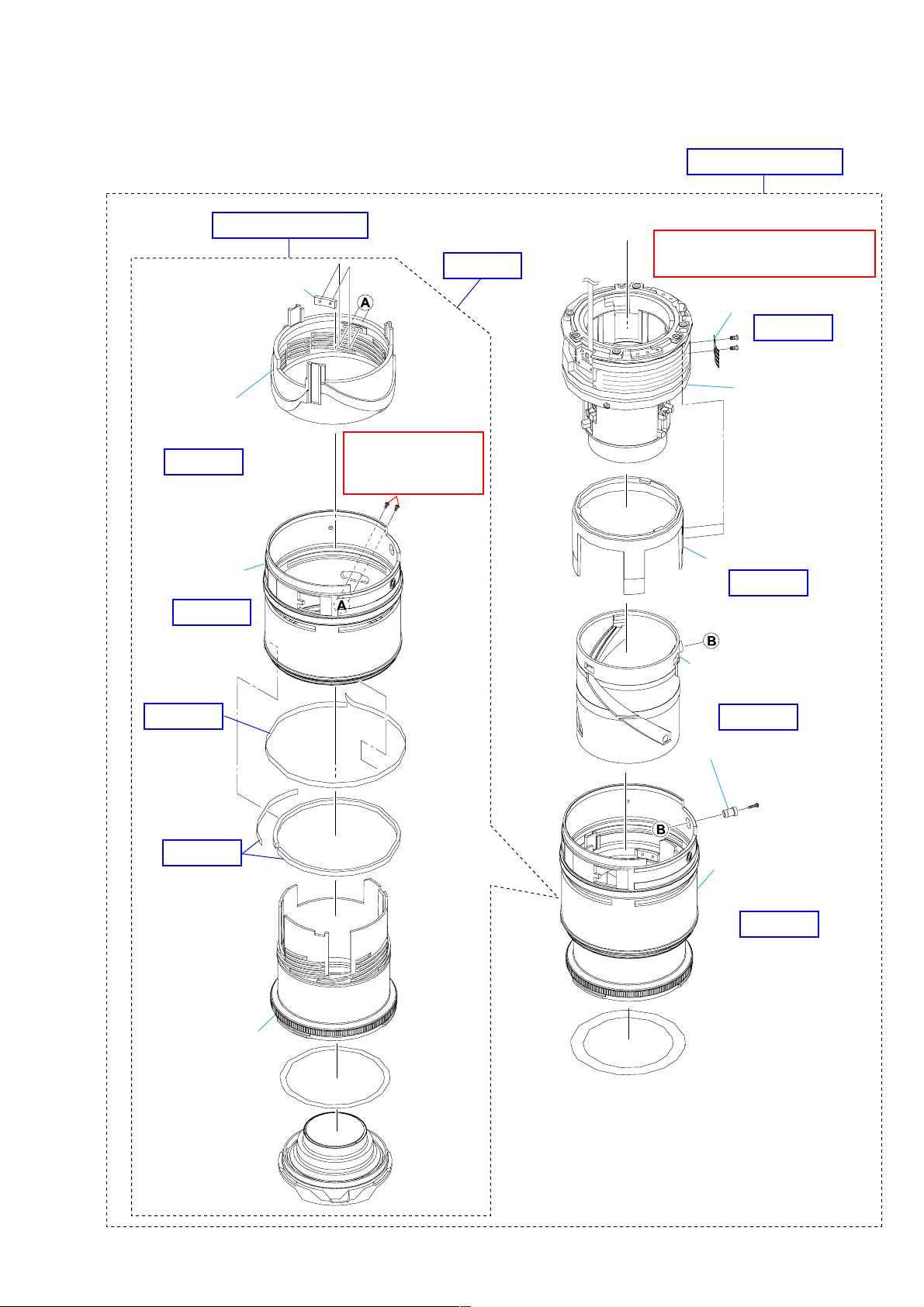
2-1-2. GEAR BARREL, ZOOM CAM BARREL AND ZOOM CONTROL TUBE BLOCK
EXPLODED VIEW
EXPLODED VIEW
FOCUS BRUSH POSITION
HELP07
ADJUSTMENT
7 Focus Stopper
4 Focus Brush
3 Joint Tube
9 1st Moving
Barrel
HELP06
FOCUS-SHIFT
/FLANGE BACK
ADJUSTMENT
Block
(See Page 2-4.)
HELP10
0 Zoom
Barrel
HELP05
HELP04
HELP03
6 Gear Barrel
HELP08
5 Zoom Cam
Barrel
HELP09
1 Zoom Coupling
Roller
2 Zoom Control
Tube Block
HELP10
8 Front Lens
Barrel
SAL1870 (3.5-5.6/18-70) (DT 18-70mm F3.5-5.6)
2-3
Ver 1.2 2007.05
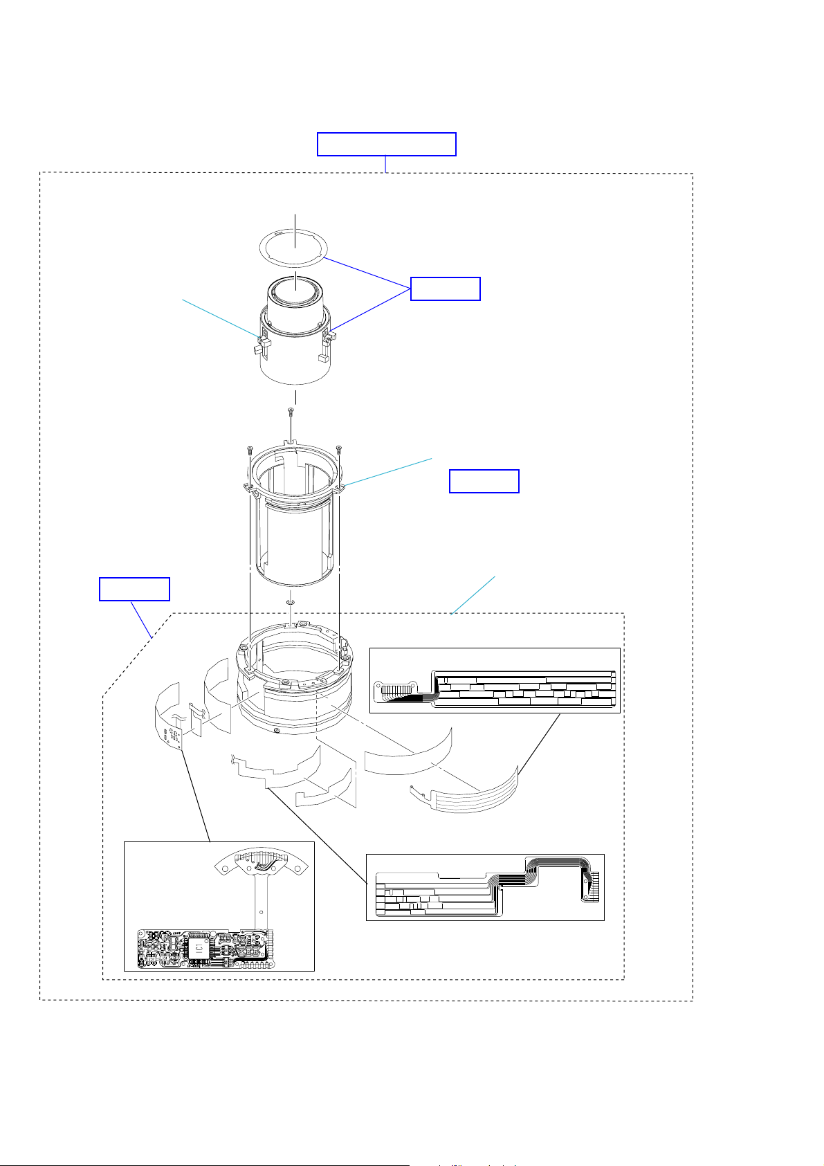
2-1-3. JOINT TUBE BLOCK
EXPLODED VIEW
1 Rear Component
Lens Block
Never disassemble this part.
HELP11
HELP13
2 Fixed Barrel
HELP12
3 Joint Tube Block
SAL1870 (3.5-5.6/18-70) (DT 18-70mm F3.5-5.6)
2-4
HELP
Note for assembling and grease applying positions are shown.
HELP01
Grease (G-80): J-6082-625-A
Grease (G-85): J-6082-626-A
Apply the grease (G-80, G-85) to the instruction part of the AF coupler.
Apply the grease (G-80)
Apply the grease (G-85)
HELP02
Grease (G-85): J-6082-626-A
Apply the grease (G-85) to the instruction part of the coupler gear.
Apply the grease (G-85)
HELP03
Attach the polyester tape (black) 10mm and friction sheet-A to the zoom barrel as illustrated.
Polyester Tape (Black) 10mm
(1mm x 40mm)
Friction Sheet-A
Gate portion
Reference line
Tip portion of the zoom barrel Enlarged section of the zoom barrel
SAL1870 (3.5-5.6/18-70) (DT 18-70mm F3.5-5.6)
HELP
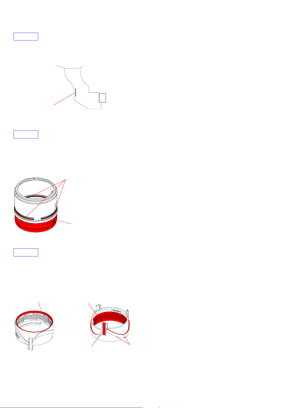
HELP04
Attach the black decoration line to the zoom barrel as illustrated.
Note: Attach the black decoration line from the opposite side of zoom scale “35” for hiding the extra scraps.
Black Decoration Line
Enlarged section of the zoom barrel
HELP05
Grease (G-116): J-6082-628-A
Anti-diffusion agent (A-20): J-6082-611-A
Apply the grease (G-116) and anti-diffusion agent (A-20) to the instruction part of the zoom barrel.
Apply the grease (G-116) (Groove portion)
Apply the anti-diffusion agent (A-20)
(Circumference of inside and outside)
HELP06
Grease (G-116): J-6082-628-A
Anti-diffusion agent (A-20): J-6082-611-A
Apply the grease (G-116) and anti-diffusion agent (A-20) to the instruction part of the 1st moving barrel.
Apply the anti-diffusion agent
(A-20) (All circumference)
Apply the grease (G-116)
(Helicoid: Inside circumference)
Apply the grease (G-116)
(Liner groove: 3 areas)
SAL1870 (3.5-5.6/18-70) (DT 18-70mm F3.5-5.6)
Apply the grease (G-116)
(Both side of cam portion: 3 areas)
HELP
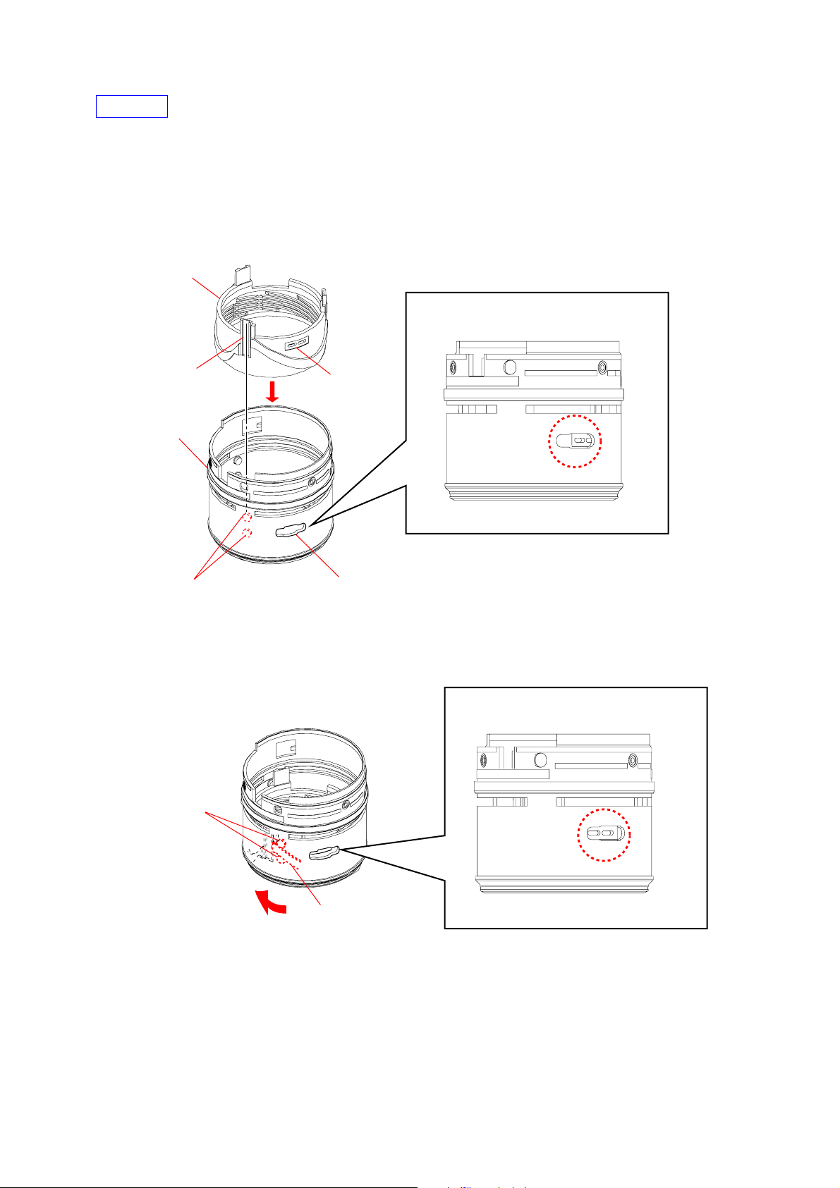
HELP07
Anti-diffusion agent (A-20): J-6082-611-A
Adhesive bond (B-10): J-6082-612-A
1. Match the positions of 1st moving barrel and zoom barrel as illustrated.
2. Insert the 1st moving barrel into the zoom barrel to the end with setting projection and linear groove.
After inserting, check that the positions of the window of zoom barrel and the hole of 1st moving barrel are as shown in the Fig.1.
1st Moving Barrel
Fig.1
Liner groove
Zoom Barrel
Projections
Hole
Window
3. Turn the 1st moving barrel to the arrow direction about 10 degrees, and engage the cam part of the 1st moving barrel and projection
of the zoom barrel as shown in the figure.
Check that the positions of the window of zoom barrel and the hole of 1st moving barrel are as shown in the Fig.2.
Fig.2
Projections of the
zoom barrel
Turn the 1st moving barrel
about 10 degrees
Cam portion of the
1st moving barrel
SAL1870 (3.5-5.6/18-70) (DT 18-70mm F3.5-5.6)
HELP
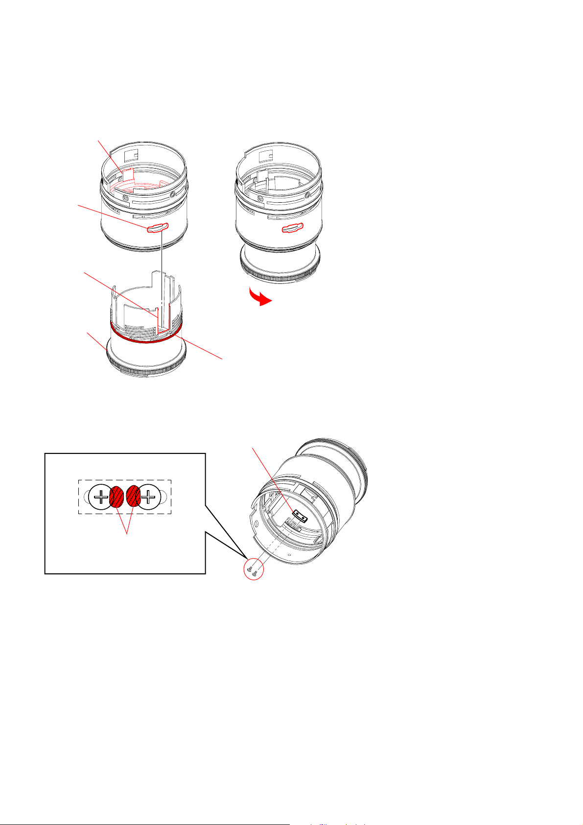
4. Apply the anti-diffusion agent (A-20) to the instruction part of the front lens barrel.
5. Match the positions of the window and the focus linear slider as shown in the figure, and attach the front lens barrel to the 1st moving
barrel.
6. Connect helicoidally the front lens barrel to the 1st moving barrel by turning it about 180 degrees in the direction of the arrow.
1st Moving Barrel
Window
Focus liner slider
About 180 degrees
Front Lens Barrel
Apply the anti-diffusion agent
(A-20) (All circumference)
7. Attach the focus stopper as shown in the figure, and fix it with the two screws tentatively.
8. After the focus-shift/flange back (f’F) adjustment is completed, apply the adhesive bond (B-10) as shown in the figure.
Focus Stopper
Apply the adhesive bond (B-10)
SAL1870 (3.5-5.6/18-70) (DT 18-70mm F3.5-5.6)
HELP
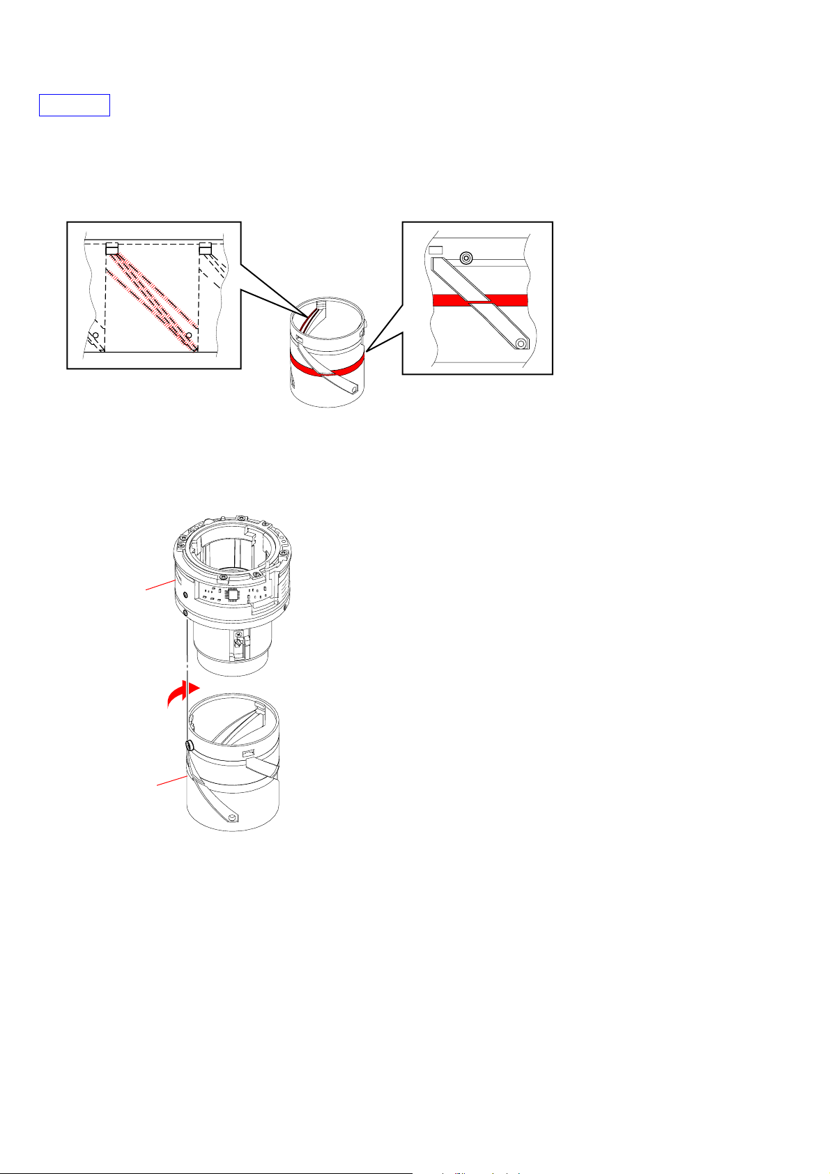
HELP08
Grease (G-116): J-6082-628-A
1. Apply the grease (G-116) to the instruction part of the gear barrel.
Apply the grease (G-116)
(Circumference area)
Apply the grease (G-116)
(Both sides: 3 areas)
2. Match the positions of joint tube block and gear barrrel, and insert the gear barrel into the joint tube block to the end as shown in the
figure.
3. Turn the gear barrel about 15 degrees from the end to the arrowed direction, and engage bayonet to the joint tube block.
Joint Tube Block
About 15 degrees
from the end to the
arrowed direction
Gear Barrel
SAL1870 (3.5-5.6/18-70) (DT 18-70mm F3.5-5.6)
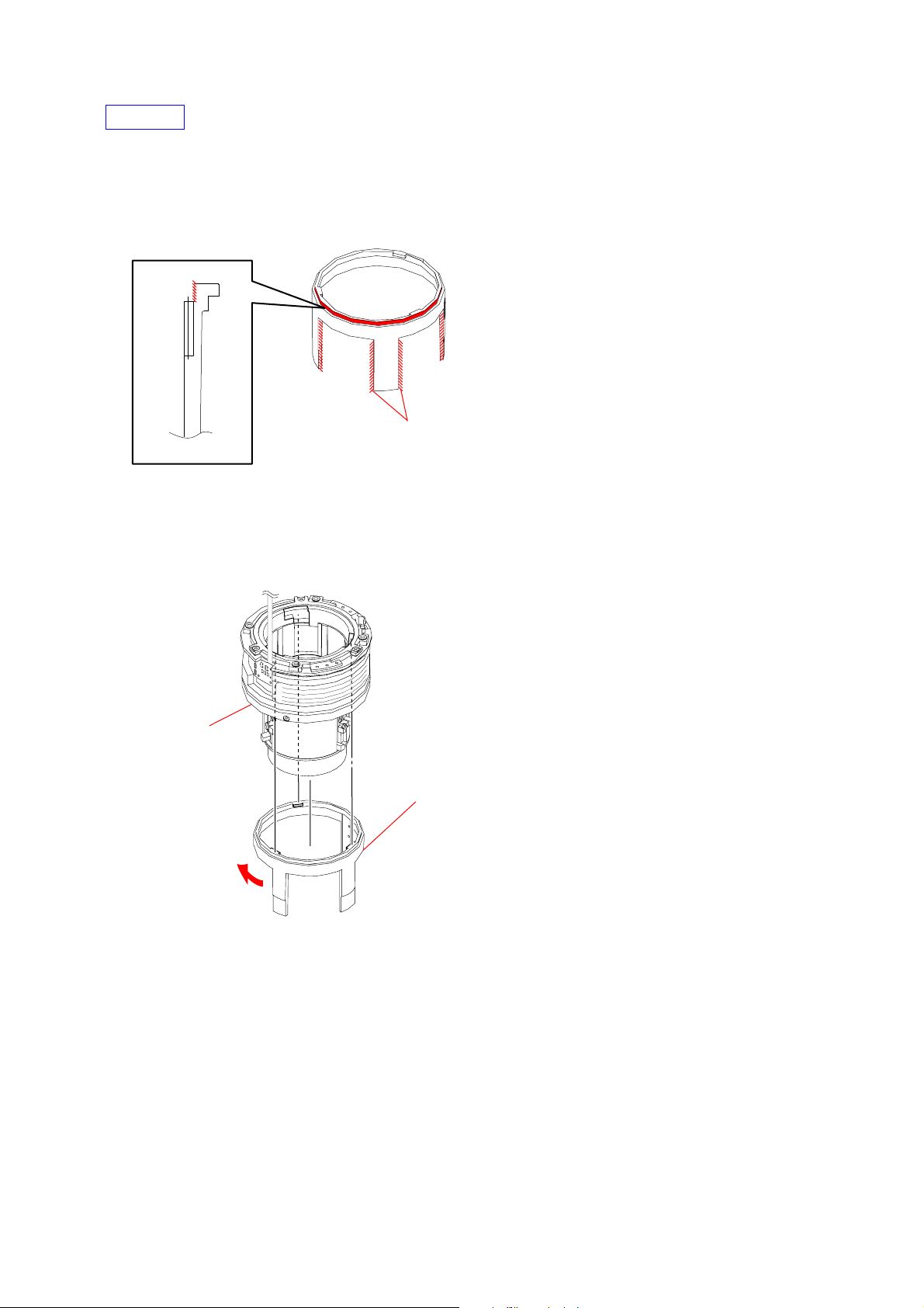
HELP
HELP09
Grease (G-116): J-6082-628-A
1. Apply the grease (G-116) to the instruction part of the zoom cam barrel.
Apply the grease (G-116) (Cam part: 3 areas) Apply the grease (G-116) (All circumference)
2. Match the positions of joint tube block and zoom cam barrel, and insert the zoom cam barrel into the joint tube block to the end as
shown in the figure.
3. Turn the zoom cam barrel about 90 degrees from the end to the arrowed direction, and engage bayonet to the joint tube block.
Joint Tube Block
About 90 degrees
from the end to the
arrowed direction
Zoom Cam Barrel
SAL1870 (3.5-5.6/18-70) (DT 18-70mm F3.5-5.6)
HELP
 Loading...