

Page 1

S-AIT
Tape Drive Unit
4-679-683-13 (2)
Operating Instructions
Before operating the unit, please read this manual
thoroughly and retain it for future reference.
SAITe1300-S
SAITe1300-F
© 2003 Sony Corporation
Page 2

Owner’s Record
The model and serial numbers are on a label on the bottom of the unit.
Record the serial number in the space provided below. These numbers provide specific information about your S-AIT
Tape Drive Unit and will be very helpful if you have to contact technical support.
Model No.
Serial No.
Safety Information
Your S-AIT Tape Drive Unit is assigned model number SDZ-S100 or SDZ-S130 for regulatory
compliance certifications. The number is indicated on the model number label on your drive along with
the rated voltage and current.
WARNING
To reduce the risk of fire or electric shock, do not expose this apparatus to rain or moisture.
To avoid electrical shock, do not open the cabinet.
Refer servicing to qualified personnel only.
Caution
The mains plug on this equipment must be used to disconnect mains power.
Please ensure that the socket outlet is installed near the equipment and shall be easily accessible.
Notice
Use the power cord set approved by the appropriate testing organization for the specific countries where this unit is to be
used.
Achtung
Zur Trennung vom Netz ist der Netzstecker aus der Steckdose zu ziehen, welche sich in der Nähe des Gerätes befinden
muß und leicht zugänglich sein soll.
Hinweis
Die 3-adrige Geräteanschlußleitung muß Typ H05VV-F oder H05VVH2-F sein und nach DIN VDE 0625 geprüft sein.
Der Stecker und die Gerätesteckdose müssen nach DIN VDE 0620 bzw DIN VDE 0625 geprüft sein. Der
Leitungsquerschnitt kann 0,5mm
Anderenfalls muß der Leitungsquerschnitt mindestens 0,75mm
2
betragen wenn die Anschlußleitung eine Länge von 2m nicht überschreitet.
2
betragen.
Hinweis
Maschinenlärminformations-Verordnung - 3. GPSGV, der höchste Schalldruckpegel beträgt 70 dB(A) oder weniger
gemäss EN ISO 7779.
Ratings
Voltage
AC 100 V - 240 V
Current
0.7 A - 0.4 A
Frequency
50 / 60 Hz
Max. Ambient Temperature
35 degrees centigrade
2
Page 3

A certified power supply cord has to be used with this equipment.
The relevant national installation and/or equipment regulations shall be considered.
A certified power supply cord not lighter than ordinary polyvinyl chloride flexible cord according to IEC 60227
(designation H05VV-F 3G 0.75 mm
synthetic rubber according to IEC 60245 (designation H05RR-F 3G 0.75 mm
Zum Netzanschluss dieses Gerätes ist eine geprüfte Leitung zu verwenden.
Es sind die zutreffenden nationalen Errichtungs- und/oder Gerätebestimmungen zu beachten.
Es ist eine geprüfte flexible PVC-ummantelte Leitung entsprechend IEC 60227 (H05VV-F 3G 0.75 mm
F 3G 0.75 mm
(Bauartkurzzeichen H05RR-F 3G 0.75 mm
2
) zu verwenden. Andernfalls ist eine flexible Leitung aus synthetischem Gummi entsprechend IEC 60245
2
or H05VVH2-F2 3G 0.75 mm2) shall be used. Alternative a flexible cord be of
2
) zu verwenden.
2
) shall be used.
2
oder H05VVH2-
ATTENTION
According to the EU Directives related to product safety, EMC and R&TTE the manufacturer of this product is Sony
Corporation, 6-7-35 Kitashinagawa Shinagawa-ku Tokyo, 141-0001 Japan. The Authorised Representative is Sony
Deutschland GmbH, Hedelfinger Strasse 61,70327 Stuttgart, Germany. For any service or guarantee matters please refer
to the addresses given in separate service or guarantee documents.
AUFMERKSAMKEIT
Im Sinne der EU Richtlinien bezüglich Produktsicherheit, EMV und R&TTE ist Sony Corporation, 6-7-35 Kitashinagawa
Shinagawa-ku Tokyo, 141-0001 Japan der Hersteller dieses Produktes. Bevollmächtigter ist Sony Deutschland GmbH,
Hedelfinger Strasse 61,D-70327 Stuttgart. Für Service oder Garantieangelegenheiten wenden Sie sich bitte an die in
separaten Service oder Garantiedokumenten angegebenen Adressen.
European Union Restriction of Hazardous Substances Directive compliant.
Entspricht der Richtlinie der Europäischen Union zur Beschränkung der Verwendung gefährlicher
Stoffe.
Laser Notice
(For Model No. SDZ-S130, SAITe1300-F only)
The equipment contains a tape drive using laser that complies with IEC 60825-1.
The equipment is classified as a CLASS 1 LASER PRODUCT.
Caution
The use of controls or adjustments or performance of procedures other than those specified herein may result in
hazardous radiation exposure.
Caution
Do not look at the end of optical connecor on the back of the tape drive with naked eyes or through optical equipment
while the power is supplied to this product. Otherwise, your eyes may be injured.
Bei diesem Laufwerk handelt es sich um ein Laser-Produkt der Klasse 1.
INFORMATION
You are cautioned that any changes or modifications not expressly approved in this manual could void your authority to
operate this equipment.
Note: This equipment has been tested and found to comply with the limits for a Class B digital device, pursuant to Part 15
of the FCC Rules. These limits are designed to provide reasonable protection against harmful interference in a residential
installation.
3
Page 4

This equipment generates, uses, and can radiate radio frequency energy and, if not installed and used in accordance with
the instructions, may cause harmful interference to radio communications. However, there is no guarantee that interference
will not occur in a particular installation. If this equipment does cause harmful interference to radio or television reception,
which can be determined by turning the equipment off and on, the user is encouraged to try to correct the interference by
one or more of the following measures:
• Reorient or relocate the receiving antenna.
• Increase the separation between the equipment and receiver.
• Connect the equipment into an outlet on a circuit different from that to which the receiver is connected.
• Consult the dealer or an experience radio/TV technician for help.
The shielded interface cable recommended in this manual must be used with this equipment in order to comply with the
limits for a digital device pursuant to Subpart B of Part 15 of FCC Rules.
If you have any questions about this product, please access Sony Support Center written in the warranty card.
Declaration of Conformity
Trade Name: SONY
Model No.: SDZ-S100, SDZ-S130
Responsible Party: Sony Electronics Inc.
Address: 16530 Via Esprillo San Diego, CA. 92127 U.S.A.
Telephone No.: 858-942-2230
This device complies with Part 15 of the FCC Rules. Operation is subject to the following two conditions:
(1) This device may not cause harmful interference, and
(2) This device must accept any interference received, including interference that may cause undesired operation.
Für Kunden in Deutschland
Diese Ausrüstung erfüllt die Europäischen EMC-Bestimmungen für die Verwendung in folgender/folgenden
Umgebung(en):
• Wohngegenden
• Gewerbegebiete
• Leichtindustriegebiete
(Diese Ausrüstung erfüllt die Bestimmungen der Norm EN55022, Klasse B.)
For Users in Japan
For Users in Korea
4
Page 5

Table of Contents
Chapter 1 Introduction
Chapter 2 Installation
Overview.......................................................................7
S-AIT Technology ........................................................7
Product Features .........................................................8
Compatible Cartridges ................................................9
Data Cartridges ............................................................... 9
Cleaning Cartridges......................................................... 9
Supported Software ....................................................9
Components and Functions .....................................10
Front .............................................................................. 10
Rear ............................................................................... 13
Bottom........................................................................... 15
About the label...........................................................16
Overview.....................................................................17
Unpacking ..................................................................17
Package Contents .....................................................18
Preparing the Host Computer ..................................18
Setting the DIP Switches ..........................................19
If necessary, change the settings as follows.................. 19
Setting the SCSI ID (SAITe1300-S only) ..................22
Setting the Loop ID (SAITe1300-F only) ..................23
Installing the S-AIT Tape Drive Unit.........................25
Connecting the Power Cable....................................26
Installing Device Drivers...........................................26
Connecting the SCSI Bus Cable
(SAITe1300-S only) .............................................27
Connecting the Optical Fiber Cable for
Fibre Channel (SAITe1300-F only) ...................29
Configuring the S-AIT Tape Drive Unit to the Host ..30
Chapter 3 Operation
Overview.....................................................................31
Turning the Unit On or Off........................................31
Turning On the Unit...................................................... 31
Turning Off the Unit ..................................................... 33
Preparing Cartridges.................................................33
Inserting a Cartridge .................................................33
Removing a Cartridge ...............................................34
5
Page 6

Chapter 4 Using the Media
Appendix
Compatible Cartridges ..............................................35
Data Cartridge............................................................35
Components and Functions........................................... 36
Setting the Write-protect Switch..............................38
Cleaning Cartridge ....................................................38
Handling Cartridges ..................................................39
Usage, Storage, and Transport Environmental
Specifications .....................................................40
Head Cleaning............................................................41
Changing the Air Filter Unit......................................42
Hardware Reset .........................................................43
Updating the Firmware..............................................43
Taking Care of the Unit .............................................43
Safety ............................................................................43
Avoiding Damage .........................................................44
Troubleshooting ........................................................45
Specifications ............................................................47
Performance .................................................................. 47
Environmental Specifications ....................................... 47
Power Specifications/Miscellaneous............................. 48
Options .......................................................................48
Index ...........................................................................49
© 2003 Sony Corporation. All rights reserved.
Trademarks
• Sony, Advanced Intelligent Tape, and Super Advanced Intelligent Tape are trademarks or registered trademarks of Sony
Corporation in this country, other countries, or both.
• Other product names are trademarks or registered trademarks of their respective owners in this country, other countries,
or both.
6
Page 7

Overview
S-AIT Technology
Introduction
The S-AIT Tape Drive Unit is a tape streamer that makes use of “S-AIT” (Super
Advanced Intelligent Tape) technology. The S-AIT drive stores large amounts
of image data on a single half-inch tape cartridge, making it the industry's
highest capacity tape drive.
Helical Scan Recording Technology
Helical scan technology, based on a very stable rotating drum/head platform,
permits accurate and reliable data recording at very high track densities. This
efficient packing density provides the industry’s leading, space-efficient
solution.
Chapter
1
Advanced Metal Evaporated (AME) Tape
S-AIT media is based on AME technology. This technology represents the
culmination of over 50 years of Sony innovation and experience in magnetic
tape technology. The AME tape formulation, with diamond-like carbon coating,
offers an extraordinary durability and reliability, up to 30,000 media passes, and
an estimated media archival life of up to 30 years.
Remote Memory in Cassette (R-MIC)
The non-volatile R-MIC chip built into the data cartridge provides quick media
loads and allows fast searches of data. The R-MIC chip contains the tape’s
system log, search map and user-definable information, allowing the drive to
advance at high speed directly to any file on the tape.
Reliability
The reliability of the S-AIT drive is in part the due to its innovative features,
such as its automatic head cleaning system and effective “leader block” tape
threading system with simplified tape load path. The drive cooling system is
also isolated from the sealed tape mechanism, thereby preventing airborne
contaminants from entering the tape path and affecting sensitive components.
Chapter 1 Introduction
7
Page 8

Product Features
Two models of S-AIT Tape Drive Units are available according to the type of
interface of your host computer.
SAITe1300-S
Uses the Ultra 160 Wide Low Voltage Differential/Single-Ended (LVD/SE)
SCSI
SAITe1300-F
Uses 2 Gbps Fibre Channel interface
Common Features
• Native storage capacity of 500 GB per cartridge (1.3 TB at 2.6:1 compression)
with the S-AIT data cartridge SAIT1-500.
• Native sustained data transfer rate of 30 MB per second.
• High data reliability with the Read After Write and Fragment Rewrite
functions, and the three levels of Error Correction Code (ECC).
• Possibility to enable and disable the Read After Write (RAW) function.
• High-speed search and tape rewind.
• Supports variable and fixed record length.
• 72 MB buffer memory.
• Very compact design that allows you to set two units side by side on a 19-inch
rack (2U height).
• Sealed mechanism with the front door and the air filter.
• Very easy to change the air filter.
• Half transparent front panel through which you can verify the cartridge even
when the door is closed.
• Sleek and elegant design.
Features of the SAITe1300-S (SCSI model)
• Ultra 160 SCSI LVD/SE interface is fully supported for host computer access.
• Burst data transfer rate of 160 MB per second, synchronous.
• Supports SCSI disconnection and arbitration.
Features of the SAITe1300-F
(Fibre Channel Interface model)
• 2 Gbps Fibre Channel interface.
• 200 MB per second burst data transfer rate.
• Private Loop, Public Loop, Point-to-Point, and Switched Fabric topologies.
• Full-duplex transfers.
• FCP2 support.
• Class of service: Class 3
Chapter 1 Introduction
8
Page 9

Compatible Cartridges
Data Cartridges
Tape cartridges used with the S-AIT Tape Drive Unit must be marked with the
SAIT-1 logo.
SAIT-1 logo
Caution
Only use cartridges designed specifically for S-AIT.
Cleaning Cartridges
To clean the read/write heads, use the S-AIT Cleaning Cartridge SAIT1-CL
supplied with the unit. For details about cleaning, see “Head Cleaning” on page
41.
Supported Software
For details about software that can be used with the S-AIT Tape Drive Unit and
supported operating systems, contact your dealer.
Chapter 1 Introduction
9
Page 10
Components and Functions
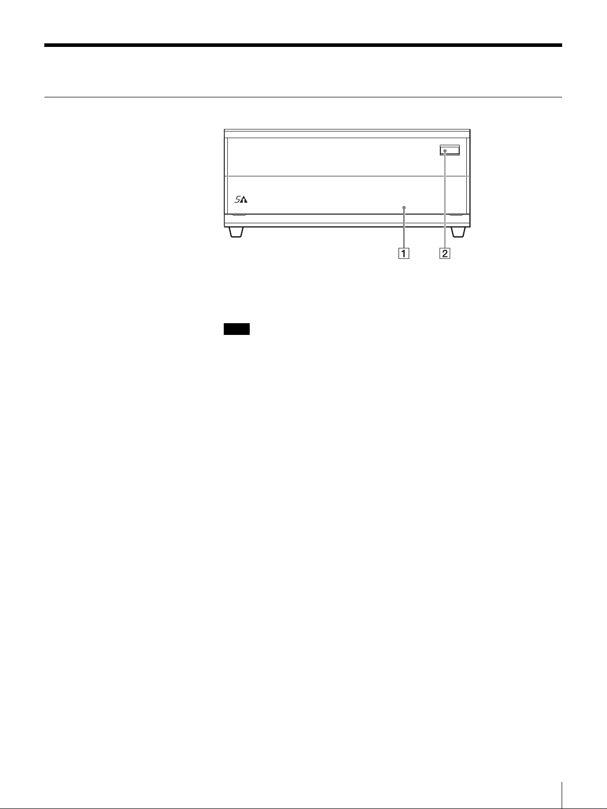
Front
A Front Door
Used to protect the front of the unit. Press the DOOR button to unlock and open
the door when inserting or removing cartridges.
Note
Even when the front door is closed and a cartridge is ejected by software, the
cartridge does not come in contact with the door. You can therefore keep the
door closed except when inserting or removing cartridges to minimize any
contamination from airborne particles.
MOTION
OPEN
TAPE
DRIVE
TAPE
ERROR
CLEANING
REQUEST
ERROR
B DOOR Button
Press to open the front door.
Chapter 1 Introduction
10
Page 11

Front door opened
1 2 3
456789
A Power Switch
Press this switch to turn the S-AIT Tape Drive Unit on or off. When you restart
the unit, be sure to wait at least 10 seconds before turning it on again.
B POWER Indicator
Lights green when the unit is on. When it flashes, the cooling fan of the unit may
be malfunctioning. If this is the case, verify that the cooling fan on the rear is
operating normally. If it is not, contact your Sony service center.
C Cartridge Slot
Used to insert and remove cartridges.
D Eject Button
Push to manually eject cartridges from the unit. The unit ejects cleaning
cartridges automatically.
E CLEANING REQUEST Indicator
Flashes yellow when the read/write heads need cleaning. For details about
cleaning, see “Head Cleaning” on page 41.
F TAPE ERROR Indicator
Flashes or lights orange when media errors occur. When media warnings occur,
the indicator flashes yellow. In this case, copy data to another cartridge.
G DRIVE ERROR Indicator
Flashes orange or yellow when drive errors occur.
H TAPE MOTION Indicator
Lights when you insert cartridges. The color of the indicator, shows whether the
cartridge is write-protected. Moreover, when the unit is operating, the indicator
flashes. The color of the flashing indicator shows the status of the unit.
I Hardware Reset Hole
Used to reset the unit in case of emergency. Using the emergency reset hole
when reading or writing data may damage your data, therefore this procedure
should only be used for maintenance purposes.
Chapter 1 Introduction
11
Page 12
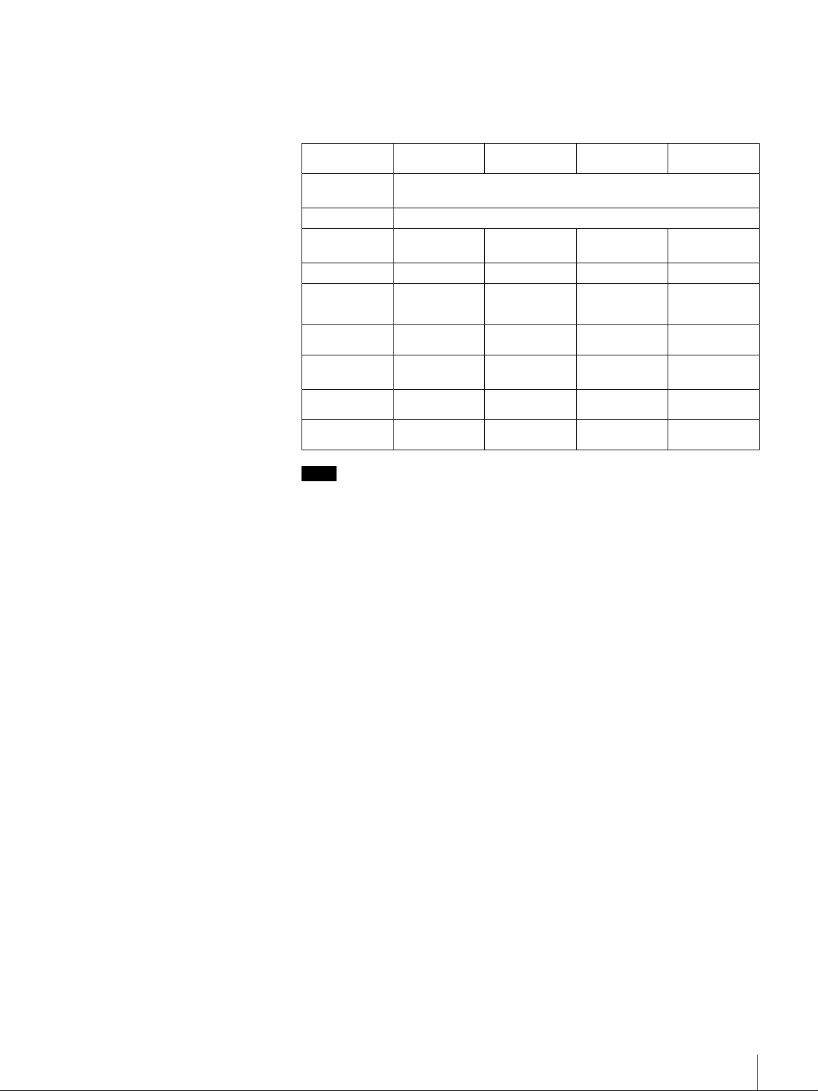
Drive Status
The indicators of the S-AIT Tape Drive Unit show the status of the unit. This
status is indicated by a combination of colors (green, orange, or yellow), and
whether the indicators are lit or flashing. Refer to the table below for
explanations about the meaning of indicator activity.
CLEANING
REQUEST
No cleaning
request
All green,
flashing
All green, lit
Orange,
flashing
Orange, lit
Yellow,
flashing
Yellow, lit
Green,
flashing
Green, lit
Off
TAPE MOTION DRIVE ERROR TAPE ERROR
Firmware update
Ejection inhibited (only when pressing the eject button)
Tape being
accessed (write)
⎯⎯Media error ⎯
Tape being
accessed
(search)
Tape loaded
(write-protected)
Tape being
accessed (read)
Tape loaded
(write-enabled)
No tape No drive error No media error
Drive error Media error Cleaning error
Drive error Media warning Cleaning request
⎯⎯Cleaning
⎯⎯⎯
⎯⎯⎯
Note
When you turn on the unit or reset it, all the indicators light green for about half
a second. They then flash repeatedly yellow from left to right for about 3
seconds, indicating that the unit is performing a self-diagnostic.
Chapter 1 Introduction
12
Page 13

Rear
SAITe1300-S
A SCSI ID Switch
Used to set the SCSI ID of the S-AIT Tape Drive Unit. Upon shipment, the SCSI
ID is 0. For details, see “Setting the SCSI ID (SAITe1300-S only)” on page 22.
B RS-232C Connector
For service use only. You do not normally need to use this connector.
C Cooling Fan and Ventilation Holes
Be careful not to block the ventilation holes. If you do, the unit may overheat,
resulting in damage.
D AC IN Connector
Connect the power cable appropriate for your country to this connector.
E Ventilation Holes
Be careful not to block the ventilation holes. If you do, the drive in the unit may
overheat, resulting in damage.
F SCSI Connector 1, 7 SCSI Connector 2
Connect the SCSI bus cable to this connector. For details about connection, see
“Connecting the SCSI Bus Cable (SAITe1300-S only)” on page 27.
Chapter 1 Introduction
13
Page 14

SAITe1300-F
1 2
346 57
A RS-232C Connector
For service use only. You do not normally need to use this connector.
B Cooling Fan and Ventilation Holes
Be careful not to block the ventilation holes. If you do, the unit may overheat,
resulting in damage.
C AC IN Connector
Connect the power cable appropriate for your country to this connector.
D Ventilation Holes
Be careful not to block the ventilation holes. If you do, the drive in the unit may
overheat, resulting in damage.
E FC Status Indicator
When the fibre channel connection is normal, the indicator is off. When the unit
is communicating with the host computer, this indicator lights green. When
there is a connection error, the indicator lights orange. In this case, reconnect the
cable or change it if necessary.
F Loop ID Jumpers
These jumpers are functional when the topology is arbitrated loop. For details,
see “Setting the Loop ID (SAITe1300-F only)” on page 23.
G Fibre Channel Connector
Connect the optical fiber cable for Fibre Channel. For details about connection,
see “Connecting the Optical Fiber Cable for Fibre Channel (SAITe1300-F
only)” on page 29.
Chapter 1 Introduction
14
Page 15

Bottom
1
2
3
A Access Cover for Service Use
Do not open this cover. For service use only.
B Dip Switch Access Cover
If you need to change the data compression settings, remove this cover to
change the DIP switch settings. For details about setting the DIP switches, see
“Setting the DIP Switches” on page 19.
C Air Filter Unit
Be careful not to block the ventilation holes of the air filter unit. If you do, the
S-AIT Tape Drive Unit may overheat, resulting in damage. Moreover,
periodically clean the air filter unit with a vacuum cleaner (monthly cleanings
recommended) and replace it yearly. For details about how to replace the air
filter unit, see “Changing the Air Filter Unit” on page 42.
Chapter 1 Introduction
15
Page 16

About the label
2 3
1
A Model number
The model number is located on the bottom of the unit, together with the serial
number.
Refer to the model and serial numbers on the label when seeking technical
support.
B Serial number
The serial number is located on the bottom of the unit, together with the model
number.
Refer to the serial and model numbers on the label when seeking technical
support.
C Number returned to the interface command
The number, which is returned to the interface command, is located on the rear
of the unit. This is the serial number reported by the application software you
use.
Chapter 1 Introduction
16
Page 17

Overview
Unpacking
Installation
This chapter describes the general procedures for positioning the S-AIT Tape
Drive Unit, connecting it to the host computer, and turning it on. This chapter
also describes initial setup. Installation and setup procedures may vary slightly
depending on your system.
Note
You will need the box and packing materials if you wish to move or transport
the unit. Retain them for future use.
Chapter
2
1
Remove the unit from the box as indicated below.
Remove the packing materials, such as plastic covers and tapes.
2
Inspect the unit for shipping damage.
If there is damage, do not use the unit. Report the damage immediately by
contacting your dealer.
Chapter 2 Installation
17
Page 18

Package Contents
After opening the package, make sure that all the following items are present.
Contact your dealer if anything is missing.
• S-AIT Tape Drive Unit (1)
• Air filter unit (1)
• Quick start guide (1)
•CD-ROM (1)
(containing this document, the quick start guide, and device drivers)
• SCSI terminator (1) (SAITe1300-S only)
Notes
• In addition to the above, other items may be included in the package.
• All the items included with the S-AIT Tape Drive unit are indicated on the
package.
Preparing the Host Computer
Prepare the host computer before installing the S-AIT Tape Drive Unit.
1
Make sure that a SCSI host adapter card or Fibre Channel host bus adapter
(FC HBA) is installed in the host computer.
2
Install all the necessary software supporting the unit on the host computer.
For details about the software that can be used with the S-AIT Tape Drive
Unit and supported operating systems, contact your dealer.
Chapter 2 Installation
18
Page 19

Setting the DIP Switches
By setting the DIP switches at the bottom of the S-AIT Tape Drive Unit, you
can:
• Choose whether to compress the data when recording.
• Choose whether the host can control data compression.
The default settings of the DIP switches is as follows.
• DC Control-1: ON
Compression is enabled.
• DC Control-2: OFF
The host can control compression.
If necessary, change the settings as follows
Caution
Before removing the access cover to change DIP switch settings of the S-AIT
Tape Drive Unit, turn off the unit and disconnect the power cable.
1
Make sure that the unit is off.
2
Remove the two screws with a screwdriver and remove the access cover
Screw
Access cover
DIP switches
Chapter 2 Installation
19
Page 20

3
Change the settings with a pointed object.
Each DIP switch is defined in the tables below.
SWA settings (SAITe1300-S)
SWA (SAITe1300-S)
ON
OFF
12345678
SWA (SAITe1300-F)
ON
OFF
12345678
SW1 Custom-1 OFF
SW2 Block Size ON
SW3 Immediate WFM OFF
SW4 Custom-4 OFF
SW5 Reserved OFF
SW6 Reserved OFF
SW7 DC Control-1 ON
SW8 DC Control-2 OFF
SWA settings (SAITe1300-F)
SW1 UA Control ON
SW2 Block Size ON
SW3 Immediate WFM OFF
SW4 Custom-4 OFF
SW5 Reserved OFF
SW6 Reserved OFF
SW7 DC Control-1 ON
SW8 DC Control-2 OFF
SWB
ON
OFF
12345678
DC
Control-1
OFF OFF
OFF ON
ON OFF
ON ON
DC
Control-2
SWB settings (Common)
SW1 Reserved OFF
SW2 Reserved OFF
SW3 Reserved OFF
SW4 Reserved OFF
SW5 Reserved OFF
SW6 Reserved OFF
SW7 Reserved OFF
SW8 Reserved OFF
Definition
Compression disabled. The host can control
compression.
Compression disabled. The host cannot control
compression.
Compression enabled. The host can control
compression.
Compression enabled. The host cannot control
compression.
Chapter 2 Installation
20
Page 21

Block Size Definition
OFF
ON
Default is 512 byte block size fix mode.
Default is variable mode.
Immediate
WFM
OFF
ON
UA Control Definition
OFF
ON
4
After changing the DIP switch settings, replace the access cover.
Enable Immed bit field in WRITE FILEMARKS command.
Ignore Immed bit field, and always return good status
immediately.
Enable to report UnitAttention (UA) sense.
Disable to report UnitAttention (UA) sense under AIX/IRIX
environment.
Definition
If you are using a SAITe1300-S (SCSI model), proceed to “Setting the SCSI ID
(SAITe1300-S only)” on page 22.
If you are using a SAITe1300-F (Fibre Channel interface model), proceed to
“Setting the Loop ID (SAITe1300-F only)” on page 23.
Chapter 2 Installation
21
Page 22

Setting the SCSI ID (SAITe1300-S only)
The SCSI ID is a unique address that identifies the SAITe1300-S to the host.
The default SCSI ID of the SAITe1300-S is 0. The unit can be configured to
SCSI ID addresses ranging from 0 to 15 (or 0 to F) using the SCSI ID switch on
the rear of the unit. Press the switch buttons to select the necessary SCSI ID
number.
Caution
• The range of SCSI IDs is 0 to 15 (or 0 to F). SCSI ID priority is 7 (highest) to
0, and then 15 (or F) to 8 (lowest).
• The SCSI ID must be different from the IDs of other peripherals on the SCSI
bus.
• Do not select the SCSI ID of the SCSI host adapter card. The priority of this
ID is usually higher than that of any device on the SCSI bus. Generally, the
SCSI ID of the host adapter is 7.
• Perform this setting before turning on the unit.
1
Before changing the SCSI ID, turn off the unit.
2
Press the button above and below the ID number with a pointed object such
as a ballpoint pen to select the SCSI ID that you want.
0
0
3
The new ID becomes effective when you restart the unit or reset the SCSI
bus.
When you are done, proceed to “Installing the S-AIT Tape Drive Unit” on page
25.
Chapter 2 Installation
22
Page 23

Setting the Loop ID (SAITe1300-F only)
You can set the Loop ID with the loop ID jumpers, if necessary. These jumpers
are functional when the topology is arbitrated loop. When the jumpers are
enabled, they acquire AL_PA through LIHA (Loop Initialization Hard
Assigned). AL_PA is acquired from the loop ID. See table “Arbitrated Loop
Physical Addresses (AL_PA) and Loop IDs” on page 24 for conversion details.
When the jumpers are disabled, acquisition of AL_PA through LIHA is not
performed, so AL_PA is acquired from LISA (Loop Initialization Soft
Assigned).
Caution
• Turn off the unit before setting the Loop ID with the loop ID jumpers. Failing
to do so may result in damage.
• Do not touch the fibre channel or jumper connectors of the unit when it is on.
Doing so may result in damage.
LOOP ID
210
345
LOOP ID
0
1
2
6
3
4
5
6
121
122
123
124
125
Reserved
Reserved
Fibre channel
connector
Jumpers
LOOP ID 0
LOOP ID 1
LOOP ID 2
LOOP ID 3
LOOP ID 4
LOOP ID 5
LOOP ID 6
LOOP ID Enable
LOOP ID Enable
Enable
Disable
Note: = CLOSED/Jumper
= OPEN/Jumper not installed
= Don't care
Chapter 2 Installation
23
Page 24

Arbitrated Loop Physical Addresses (AL_PA) and Loop IDs
7-bit Loop ID
(Hex) (Decimal) (Hex) (Hex) (Decimal) (Hex) (Hex) (Decimal) (Hex)
00 0 EF 2B 43 A3 56 86 4D
01 1 E8 2C 44 9F 57 87 4C
02 2 E4 2D 45 9E 58 88 4B
03 3 E2 2E 46 9D 59 89 4A
lowest priority
04 4 E1 2F 47 9B 5A 90 49
05 5 E03048985B9147
06 6DC3149975C9246
07 7 DA3250905D9345
08 8 D933518F5E9443
09 9 D63452885F953C
0A 10 D5 35 53 84 60 96 3A
0B 11 D4 36 54 82 61 97 39
0C 12 D3 37 55 81 62 98 36
0D 13 D2 38 56 80 63 99 35
0E 14 D1 39 57 7C 64 100 34
0F 15 CE 3A 58 7A 65 101 33
10 16 CD 3B 59 79 66 102 32
11 17 CC 3C 60 76 67 103 31
12 18 CB 3D 61 75 68 104 2E
13 19 CA 3E 62 74 69 105 2D
14 20 C9 3F 63 73 6A 106 2C
15 21 C7 40 64 72 6B 107 2B
16 22 C6 41 65 71 6C 108 2A
17 23 C5 42 66 6E 6D 109 29
18 24 C3 43 67 6D 6E 110 27
19 25 BC 44 68 6C 6F 111 26
1A 26 BA 45 69 6B 70 112 25
1B 27 B9 46 70 6A 71 113 23
1C 28 B6 47 71 69 72 114 1F
1D 29 B5 48 72 67 73 115 1E
1E 30 B4 49 73 66 74 116 1D
1F 31 B3 4A 74 65 75 117 1B
20 32 B2 4B 75 63 76 118 18
21 33 B1 4C 76 5C 77 119 17
22 34 AE 4D 77 5A 78 120 10
23 35 AD 4E 78 59 79 121 0F
24 36 AC 4F 79 56 7A 122 08
25 37 AB 50 80 55 7B 123 04
26 38 AA 51 81 54 7C 124 02
27 39 A9 52 82 53 7D 125 01
28 40 A7 53 83 52 — — —
29 41 A6 54 84 51 — — —
2A 42 A5 55 85 4E — — —
8-bit
AL_PA
7-bit Loop ID
8-bit
AL_PA
7-bit Loop ID
8-bit
AL_PA
highest priority
Chapter 2 Installation
24
Page 25

Installing the S-AIT Tape Drive Unit
The S-AIT Tape Drive Unit weights about 7 kg (15.4 lb.) and has the following
dimensions. Make sure that the surface where you will install the S-AIT Tape
Drive Unit is appropriate before installing the unit.
Note
Install the S-AIT Tape Drive Unit on a horizontal surface near an AC power
outlet. Make sure that you leave gap of about 150 mm (5.9 in.) behind the rear
of the unit to allow air to circulate.
86 mm (3.4 in.)
210 mm
(8.3 in.)
Front
50 mm (2.0 in.)
210 mm (8.3 in.)
372 mm (14.6 in.)
50 mm (2.0 in.)
372 mm (14.6 in.)
Rear
150 mm
(5.9 in.)
Recommended positioning of the unit
• Always position the unit horizontally.
• Away from moving air, such as fans, open windows, or air conditioners.
• Away from devices such as facsimiles to avoid toner and paper dust.
The S-AIT Tape Drive Unit should not be stacked. Do not place anything on top
of the unit.
Chapter 2 Installation
25
Page 26

Connecting the Power Cable
1
Verify the power cable plug to make sure that it matches the AC IN
connector receptacle.
2
Make sure that the electrical outlet you use to connect the unit is properly
grounded.
3
Connect one end of the power cable to the AC IN connector and the other
end to the power outlet.
Note
If the S-AIT drive does not come with a power cable, make sure that you
connect a power cable appropriate for your country to this connector.
Installing Device Drivers
A device driver is host firmware that allows the S-AIT Tape Drive Unit to
interact with a variety of hosts.
If your software requires it, install the appropriate device driver for your system
from the supplied CD-ROM. Refer to the instructions on the CD-ROM to install
device drivers.
The latest device drivers and documentation for the S-AIT Tape Drive Units are
available online. Contact your dealer for details or visit the Sony Web site
(http://www.sony.net/Products/storagesolution/).
If you are using a SAITe1300-S (SCSI model), proceed to “Connecting the
SCSI Bus Cable (SAITe1300-S only)” on page 27.
If you are using a SAITe1300-F (Fibre Channel interface model), proceed to
“Connecting the Optical Fiber Cable for Fibre Channel (SAITe1300-F only)”
on page 29.
AC Power
Chapter 2 Installation
26
Page 27

Connecting the SCSI Bus Cable (SAITe1300-S only)
Connect the SAITe1300-S (SCSI model) and the host computer with a SCSI
cable. This section describes how to do so. Use an Ultra 160/m SCSI LVD cable
commonly sold in stores to connect the unit to the SCSI bus. The SAITe1300-S
uses a 68-pin half pitch connector.
Caution
• Do not connect the SAITe1300-S to a HVD (High Voltage Differential) SCSI
bus. If you do, the unit or other devices on the SCSI bus may be damaged.
• Turn off all the connected devices before connecting the SCSI cable,
including the SAITe1300-S and the host computer.
• If the SAITe1300-S is the last or only device on the SCSI bus, make sure that
you connect the supplied terminator to the open connector.
• Make sure that the SCSI connectors are securely connected.
• With LVD (Low Voltage Differential) SCSI, make the total length of the
SCSI cable (internal and external) connecting the host computer and the
device at the end of the SCSI bus shorter than 12 m (39.4 ft.). On an LVD bus
with a single device, make this length shorter than 25 m (82 ft.). The
SAITe1300-S internal cable length is 25 cm (9.8 in.).
• SCSI cables cannot be branched.
1
Make sure that the host computer and the SAITe1300-S are off.
2
Connect the SCSI cable and terminator as shown below.
The SCSI cable can be up to 24.7 m (81 ft.) long. (The SAITe1300-S
internal cable length is 25 cm (9.8 in.).)
SCSI connector
Host computer
SCSI cable
A SCSI bus allows you to connect up to fifteen peripherals to the host computer,
including the unit.
Terminator
Chapter 2 Installation
27
Page 28

When the SAITe1300-S is one of several devices on the
SCSI bus
1
Turn off all SCSI devices on the SCSI bus, including the SAITe1300-S.
Caution
When connecting or disconnecting a SCSI cable to SCSI devices
(including the SAITe1300-S), turn off all the SCSI devices. Failing to do
so may result in damage.
2
Connect the SCSI cable to the next device on the SCSI bus, connect the
terminator to the last device on the bus, then issue the host command to
resume operation.
SCSI
connector
SCSI devices
Host computer
SCSI cable
Notes
Terminator
• The total length of the SCSI cables between the host computer and the last
device should be less than 12 m (39.4 ft.). (The SAITe1300-S internal cable
length is 25 cm (9.8 in.).)
• If the SAITe1300-S is the last device on the SCSI bus, make sure that you
connect the supplied terminator to the open connector.
When you are done, proceed to “Configuring the S-AIT Tape Drive Unit to the
Host” on page 30.
Chapter 2 Installation
28
Page 29

Connecting the Optical Fiber Cable for Fibre Channel (SAITe1300-F only)
The SAITe1300-F is equipped with an interface that complies with the Fibre
Channel standards with the following specifications.
• Short-wave laser
• 200 MB/sec
• Duplex LC Fibre Channel connectors
The equipment (HBA, hub, switch, etc.) to be connected to the SAITe1300-F
must be of the same type.
Use an optical fiber cable with the following specifications.
• Duplex LC Fibre Channel connectors
• 50/125 µm multimode optical fiber cable
Caution
• If your interface and optical fiber cable are different types, the unit may not
operate correctly when connected.
• Turn off the unit when connecting or disconnecting a cable to the fibre
channel connector. Failing to do so may result in damage.
• Never touch the fibre channel connector of the unit when the unit is on. Doing
so may result in damage.
Host bus adaptor
(FC HBA)
Host computer
or
HUB, switch, etc.
FIBRE CHANNEL
Optical fiber cable for fibre channel*
* 50/125 µm, MMF, Duplex LC
FIBRE CHANNEL
FIBRE CHANNEL
Optical fiber
cable for fibre
channel*
Chapter 2 Installation
29
Page 30

Configuring the S-AIT Tape Drive Unit to the Host
Configure the S-AIT Tape Drive Unit as follows.
1
Turn on the S-AIT Tape Drive Unit.
For details, see “Turning the Unit On or Off” on page 31.
2
To configure the unit for use, refer to the documentation of the host
computer and software.
Chapter 2 Installation
30
Page 31

Operation
Overview
This chapter describes how to turn the unit on and off, as well as how to insert
and eject cartridges.
Turning the Unit On or Off
Turning On the Unit
1
Press the DOOR button to unlock and open the front door.
Chapter
3
Chapter 3 Operation
31
Page 32

2
Press the power switch on the front panel.
The POWER indicator lights green and the unit starts.
Then four status indicators change as follows as the unit is starting.
• All the indicators light green for about half a second.
• They then repeatedly flash yellow form left to right for about 3 seconds,
indicating that the unit is performing a self-diagnostic.
• Finally, all the indicators go out. (If there is a cartridge in the unit, the
TAPE MOTION indicator lights green or yellow.)
Caution
• If the POWER indicator flashes when the unit starts, the cooling fan of the unit
may be malfunctioning. If this is the case, verify that the cooling fan on the
rear is operating normally. If it is not, contact your Sony service center.
• If the status indicators do not behave as described above, see chapter 1.
• Do not push down the front door when it is opened. Doing so may result in
damage.
Notes
• If you start the host computer before the SAITe1300-S, the SCSI ID is not
detected correctly. Therefore, you must always start the SAITe1300-S before
starting the host computer.
• If the S-AIT Tape Drive Unit does not behave as described above, see
“Troubleshooting” on page 45.
Chapter 3 Operation
32
Page 33

Turning Off the Unit
1
2
Caution
Do not turn off the S-AIT Tape Drive Unit when it is in use or there is a cartridge
in the unit, as this could damage data.
Note
After turning off the S-AIT Tape Drive Unit, wait at least 10 seconds before
turning it on again.
Preparing Cartridges
Make sure that cartridges are not write-protected and prepare them for use.
Verify whether the write-protect switch is in the write-enable position. For
details, see “Setting the Write-protect Switch” on page 38.
Press the DOOR button to unlock and open the front door.
Press the power switch on the front panel.
Inserting a Cartridge
1
2
3
Press the DOOR button to unlock and open the front door.
Press the power switch on the front panel.
The POWER indicator lights green and the TAPE MOTION, DRIVE
ERROR, TAPE ERROR and CLEANING REQUEST indicators flash as
the unit performs a self-diagnostic.
When the four indicators go out, insert your cartridge.
If the indicators do not go out, see chapter 1 or try the troubleshooting
procedures in the appendix to determine the problem.
Chapter 3 Operation
33
Page 34

4
Apply gentle pressure to the back of the cartridge until the unit takes the
cartridge and loads it.
Caution
Do not apply force to the cartridge after the unit starts loading it. Otherwise,
the cartridge may rush out of the unit when it is ejected.
5
Close the front door to minimize any contamination from airborne
particles.
When the cartridge is loaded, the TAPE MOTION indicator lights green or
yellow.
Notes
• The host software controls the reading and writing of tapes.
• For details about the status of the unit as shown by the indicators on the front
of the unit, see chapter 1.
Removing a Cartridge
When the cartridge is automatically ejected by your
software
1
Press the DOOR button to unlock and open the front door.
2
Remove the cartridge from the unit and close the door.
When you eject the cartridge manually
1
Press the DOOR button to unlock and open the front door.
2
Press the Eject button. The cartridge is ejected automatically.
Eject button
3
Remove the cartridge from the unit and close the door.
Caution
Do not push the eject button when the TAPE MOTION indicator is flashing.
This may destroy data on the tape.
Chapter 3 Operation
34
Page 35

Using the Media
Compatible Cartridges
S-AIT Tape Drive Unit uses:
• S-AIT data cartridges
• S-AIT cleaning cartridges
Only use the cartridges above with your S-AIT Tape Drive Unit. Do not use
other types of cartridges, such as LTO Ultrium, SDLT, or DLT.
Data Cartridge
Chapter
4
S-AIT data cartridges contain a half inch AME (Advanced Metal Evaporated)
tape. When processing the tape, the S-AIT Tape Drive Unit uses an advanced
helical scan recording technology known for its high data density, outstanding
data transfer performance, as well as its reliability and durability.
The cartridges also incorporate a built-in Remote MIC (8 KB) to enhance the
accessibility.
Chapter 4 Using the Media
35
Page 36

Components and Functions
4
1 2
3
TOP
A Insertion Guide
The insertion guide is a large notch preventing you from inserting the cartridge
incorrectly or inserting cartridges of other types into the unit.
B Insertion Indicator
This arrow shows the direction in which the cartridge must be inserted into the
drive.
C Label Area
Area where you can affix labels to identify your S-AIT data cartridges.
Note
Make sure that you affix your label squarely into the label area as protruding
labels can cause loading and ejection problems.
D Write-protect Switch
This switch is used to prevent data from being written to the tape. For details,
see “Setting the Write-protect Switch” on page 38.
Note
The Sony S-AIT Data Cartridge SAIT1-500 write-protect switch is orange. The
Sony S-AIT Cleaning Cartridge SAIT1-CL write-protect switch is blue.
Chapter 4 Using the Media
36
Page 37

Bottom
89q
q
5a
567
a
;
E Recognition Holes
Used by the unit to determine the type of cartridge. S-AIT data cartridge
recognition holes are all closed. S-AIT cleaning cartridge holes are closed
except hole .
Caution
Do not open the recognition holes as this may prevent the unit from recognizing
the type of cartridge correctly.
F Reel Lock
Used to prevent the tape from moving when it is outside the unit. When you
insert a cartridge into the unit, its reel locks are released automatically.
Caution
Do not close the reel lock as this may cause loading problems.
G Positioning Hole
Used by the unit to determine the position of the cartridge in the unit.
Caution
Do not close the positioning hole as this may cause loading problems.
H Leader Block
The tape is attached to the leader block. When you insert a cartridge into the
unit, the leader block is extracted from the cartridge, loaded onto a nonremovable take-up reel, and then the tape is wrapped around the drum.
Caution
Do not pull the leader block from the cartridge as this may cause loading
problems.
I Spring-loaded Hub
Used by the unit to rotate the cartridge reel.
Caution
Do not close the spring-loaded hub as this may cause loading problems.
Chapter 4 Using the Media
37
Page 38

J Reel Lock
Used to prevent the tape from moving when it is outside the unit. When you
insert a cartridge into the unit, its reel locks are released automatically.
Caution
Do not close the reel lock as this may cause loading problems.
K Positioning Hole
Used by the unit to determine the position of the cartridge in the unit.
Caution
Do not close the positioning hole as this may cause loading problems.
Setting the Write-protect Switch
The position of the write-protect switch on the cartridge determines whether you
can write to the tape. If you do not want to write to the tape, slide the switch in
the direction of the arrow as illustrated below.
Cleaning Cartridge
Write-protect position
(SAFE)
Write-enable position
(REC)
Use a Sony S-AIT Cleaning Cartridge SAIT1-CL to clean the drive heads. The
unit determines when heads need to be cleaned and alerts you accordingly. For
details about how to use the cleaning cartridge, see “Head Cleaning” on page 41.
Chapter 4 Using the Media
38
Page 39

Handling Cartridges
Handling or storing S-AIT cartridges incorrectly can damage them or their
tapes. Follow the guidelines below to avoid damaging your cartridges.
Handling precautions
• Before using cartridges, let them acclimate themselves to the normal
• Verify whether cartridges are damaged before using them.
• Verify whether foreign objects such as labels are affixed to the cartridges as
• Do not insert damaged cartridges into the S-AIT Tape Drive Unit. Damaged
• Do not pull the leader block or the tape out of cartridges as this may damage
• Do not handle the tape outside cartridges as this may damage the tape’s
• Do not subject cartridges to strong vibrations.
• Do not drop cartridges. If you do, verify that the reel lock opening to make
• Never open cartridge cases as this may expose the tape to contamination and
• Never affix labels elsewhere than on the repressed label area as doing so may
• The write-protect switch of cartridges is used to prevent writing to the tape by
• If the S-AIT Tape Drive Unit is used in a high-humidity environment or a
• Remove cartridges from the unit when they are not used or before turning the
• Dispose of used cartridges according to your local regulations on waste
operating environment for at least 24 hours.
they may cause loading problems.
cartridges can interfere with the reliability of the unit.
the cartridge braking mechanism and/or the tape.
surface or edges.
sure that the small plastic tabs inside are still visible. If they are not, do not use
the cartridge. Inspect the cartridge for any obvious cracks or other physical
damage.
physical damage.
cause loading problems.
accident. If you do not want to write to a cartridge, slide it to the write-protect
position. (For details, see “Setting the Write-protect Switch” on page 38.)
location subject to wide variations in temperature, condensation may prevent
cartridge read/write operations.
unit off.
disposal.
Storage precautions
• Store cartridges in an appropriate environment (see page 40 for details).
• Always place cartridges in their plastic cases as soon as possible when you are
not using them.
• Do not place cartridges on or near devices that may produce magnetic fields
such as computers or monitors as this may erase the data on the tape.
• Do not store cartridges in a high humidity environment, direct sunlight, close
to heat sources, dusty locations, or locations subject to intense vibrations.
• When placing cartridges in archival storage, make sure that you place them
vertically.
• When storing cartridges, we recommend that they are write-protected.
• Do not degauss the cartridge as degaussing may render the tape unusable.
Chapter 4 Using the Media
39
Page 40

Usage, Storage, and Transport Environmental Specifications
Before using cartridges, let them acclimate themselves to the operating
environment for at least 24 hours.
Operating environment
Temperature 5 to 35°C (41 to 95°F)
Relative humidity 20 to 80% (non-condensing)
Wet bulb temperature 26°C (79°F)
Storage environment
Temperature 16 to 32°C (61 to 90°F)
Relative humidity 20 to 60% (non-condensing)
Wet bulb temperature 26°C (79°F)
Transport environment (When packed)
Temperature -23 to 48°C (-9 to 118°F)
Relative humidity 5 to 80% (non-condensing)
Wet bulb temperature 26°C (79°F)
Chapter 4 Using the Media
40
Page 41

Head Cleaning
Appendix
The S-AIT Tape Drive Unit is equipped with an automatic head cleaning system
and was developed to require only a minimum of cleaning. Yet, to maintain the
unit in peak condition, the unit determines when head cleaning using a cleaning
cartridge is necessary. When cleaning is necessary, the CLEANING REQUEST
indicator flashes yellow.
OPEN
TAPE
DRIVE
TAPE
MOTION
CLEANING
ERROR
ERROR
REQUEST
1
Insert an S-AIT cleaning cartridge into the unit.
The unit loads the cartridge and cleans the heads. During the cleaning
cycle, the CLEANING REQUEST indicator lights yellow.
2
When cleaning ends, the unit ejects the cartridge and the CLEANING
REQUEST indicator goes out.
Note
An S-AIT cleaning cartridge is good for 50 uses. The cleaning cartridge R-MIC
keeps track of how many times the cartridge is used. When the cleaning
cartridge reaches the end of its life, the unit ejects it immediately without
cleaning. In this case, dispose of it and repeat the operation with a new cleaning
cartridge.
Appendix
41
Page 42

Changing the Air Filter Unit
We recommend that you replace the air filter unit at least once a year. Consult
your dealer to purchase air filter units.
Note
We recommend that you clean the air filter unit once a month with a vacuum
cleaner.
1
Prepare a new air filter unit.
2
Turn off the unit.
3
Disconnect all cables from the unit.
4
Turn the unit upside-down.
There are three latches on the air filter unit.
5
Push the air filter as illustrated below to release the latch, and then lift it.
6
Repeat steps 4 and 5 in reverse to install the new air filter unit.
Appendix
42
Page 43

Hardware Reset
In case of an emergency, you can reset the unit by inserting a pointed object such
as a paper clip into the hardware reset hole.
Caution
Resetting the unit with the hardware reset hole may cause you to lose data.
Under normal circumstances, the hardware reset is only for manufacturing or
repair purposes.
Hardware
reset hole
Updating the Firmware
You can update the S-AIT Tape Drive Unit firmware by downloading the new
version of the firmware to your unit through the SCSI bus. To obtain up-to-date
firmware and installation instructions, contact your dealer or visit the Sony Web
site (http://www.sony.net/Products/storagesolution/).
Taking Care of the Unit
Safety
Power
• Only use 100 V - 240 V AC.
• Avoid plugging the unit to the same power outlet as high-current equipment
such as copiers or shredders.
Power Cable Precautions
• Do not crush the cable or place heavy objects on it. If the cable insulation
appears worn or broken, do not use the cable.
• Always unplug the cable by holding the plug. Never pull the cable itself as this
may break it.
• If the unit is not used for a prolonged period, unplug the cable from the power
outlet.
Appendix
43
Page 44

Avoiding Damage
Avoid Shock and Vibrations
Intense shock, such as from dropping the unit, may damage it.
Environmental Considerations
Do not store or use the unit in locations subject to:
• high humidity
• excessive dust
• high temperature
• intense vibrations
• direct sunlight
• sudden changes in temperature
Proper Ventilation
To avoid overheating, install the unit where air can circulate freely around the
case, and do not cover it during operation. The unit may malfunction if the
internal temperature rises too high.
Avoid Sudden Changes in Temperature
If the unit is moved from a cool to a warm place, or if the room temperature
suddenly rises, moisture may condense inside the case. After a sudden change
in temperature, wait at least one hour before turning on the unit. Turning on the
unit with condensation inside and inserting a cartridge may damage the tape or
the unit.
Abnormal Occurrences
If the unit behaves abnormally, or it begins to smell or smoke, unplug it
immediately from the power outlet and contact your Sony service center.
Cleaning the Cabinet
Wipe the cabinet with a soft, dry cloth. For heavy dirt, wipe with a soft cloth
moistened with a gentle detergent, and then wipe it again with a soft, dry cloth.
Do not use alcohol, paint thinner, sprays, or other volatile solvents, as they may
damage the finish of the cabinet.
Appendix
44
Page 45

Troubleshooting
Before contacting a Sony service center, verify the following. If the problem
persists, contact your Sony service center.
The unit does not start (the POWER indicator does not
light)
• Verify that the power cable is connected correctly and that it is not damaged.
Replace it if necessary.
• Try another power outlet.
The POWER indicator flashes green
Verify that the cooling fan on the rear is operating normally.
The SAITe1300-S (SCSI model) and the host computer
cannot communicate with each other
• Verify that the host computer is on.
• Verify that the SCSI ID of the unit is unique. Duplicate SCSI IDs cannot be
used on one SCSI bus. The new ID becomes effective when you restart the
unit or reset the SCSI bus. For details, see “Setting the SCSI ID (SAITe1300S only)” on page 22.
• Verify that the SCSI cable is correctly connected to the unit and the host
computer. Push the connectors into their receptacles and, if necessary, tighten
the screws until they are firmly seated. For details, see “Connecting the SCSI
Bus Cable (SAITe1300-S only)” on page 27.
• Verify that the SCSI bus is terminated correctly. For details, see “Connecting
the SCSI Bus Cable (SAITe1300-S only)” on page 27.
• Verify that all the connector pins are undamaged. Remove the terminator and
cable connectors, and inspect them for bent, recessed, or missing pins.
Replace the damaged component if necessary.
• Verify whether there are too many SCSI devices on the SCSI bus. The
maximum permissible number of SCSI devices on the SCSI bus is sixteen,
including the SCSI host adapter card.
• Verify that all the connected SCSI devices are LVD devices.
The SAITe1300-S is an LVD device. Do not connect HVD devices to the unit.
• Verify the length of the SCSI cable. If your SAITe1300-S is the only device
on the SCSI bus, make sure that the total length does not exceed 24.7 m (81
ft.). If there are other devices on the SCSI bus, make sure that the total length
does not exceed 12 m (39.4 ft.). For details, see “Connecting the SCSI Bus
Cable (SAITe1300-S only)” on page 27.
Appendix
45
Page 46

The SAITe1300-F (Fibre Channel interface model) and the
host computer cannot communicate with each other
• Verify that the host computer is on.
• Verify the FC status indicator at the rear of the unit. If it is lit orange, there is
a connection error. In this case, reconnect the cable or change it if necessary.
• Verify that an optical fiber cable is correctly connected from the unit to the
host computer, hub, or switch.
• Verify that the optical fiber cable is of the appropriate type. For details, see
“Connecting the Optical Fiber Cable for Fibre Channel (SAITe1300-F only)”
on page 29.
• Verify that the Loop ID is set correctly. For details, see “Setting the Loop ID
(SAITe1300-F only)” on page 23.
Your software does not detect the unit
• Verify that your software supports the S-AIT Tape Drive Unit. For details
about software that can be used on the S-AIT Tape Drive Unit and supported
operating systems, contact your dealer.
• Verify that the software is correctly installed and set up on the host computer.
• If the software requires a device driver, install the appropriate device driver
from the supplied CD-ROM. For details, see “Installing Device Drivers” on
page 26.
Media error detected
Push the eject button. If the cartridge is ejected, reset the unit and try to insert a
new one.
Drive error detected
Push the eject button. If the cartridge is ejected, reset the unit and try to insert a
new one.
Appendix
46
Page 47

Specifications
Performance
Storage capacity 500 GB (uncompressed with 600 m S-AIT Data Cartridge)
1.3 TB
(2.6:1 compression ratio
Data transfer rate 30 MB/sec (uncompressed
1
with 600 m S-AIT Data Cartridge)
2
)
Burst data transfer rate
160 MB/s (maximum, synchronous, SCSI)
200 MB/s (maximum, Fibre Channel)
Bit error rate Less than 10
Initialize time Less than 5 seconds
Load time Less than 23 seconds
Unload time Less than 21 seconds
Rewind time Less than 100 seconds3 (with 600 m S-AIT Data Cartridge)
Search time Average 70 seconds
1
Compression ratios vary according to the type of data.
2
The transfer rate may differ according to your system performance.
3
Does not include retry time.
Environmental Specifications
Operating Temperature range 5 to 35°C (41 to 95°F)
Non-operating Temperature range -40 to 70°C (-40 to 158°F)
-17
3
3
Humidity range 20 to 80% (non-condensing)
Maximum wet bulb temperature 26°C (79°F)
Humidity range 10 to 90% (non-condensing)
Temperature gradient
Operating less than 10°C/hour
Non-operating less than 20°C/hour
Humidity gradient
Non-operating less than 30%/hour
Operating altitude
0 to 3,048 m (0 to 10,000 ft.)
ESD Discharge less than 15 kV (no operation failure)
Voltage less than 20 kV (no unit damage)
Appendix
47
Page 48

Vibrations Operating swept sine 5 to 500 Hz
Shock Operating half sine 5G peak 3 ms (no data loss)
Power Specifications/Miscellaneous
Power 100 V - 240 V AC ± 10% (50 to 60 Hz)
Noise level Streaming read/write 50 dB (A)
External dimensions
Mass 7 kg (15.4 lb.)
In the interest of product improvement, specifications are subject to change
without notice.
0.25G peak 1 Octave/min.
Non-operating swept sine 5 to 500 Hz
0.5G peak 1 Octave/min.
Non-operating half sine 90G peak 2 ms (no unit damage)
0.7 A (100 V AC)
0.4 A (240 V AC)
210 × 86 × 372 mm (W × H × D) (excluding protrusions)
(8.3 × 3.4 × 14.6 in.)
Options
S-AIT data cartridge
500 GB uncompressed, 1300 GB compressed, 600 m (1968 ft.) tape
Model: SAIT1-500
S-AIT cleaning cartridge
Model: SAIT1-CL
Rack mount kit
Model: ACY-RKSE
Used to mount two units side by side in an EIA standard
19-inch rack.
For details about these options and the air filter units, contact your dealer.
Appendix
48
Page 49

Index
M
Model number .............................. 16
A
Air filter unit ................................. 42
Appendix ...................................... 41
Avoiding damage ......................... 44
C
Cartridges ..................... 9, 33, 35, 39
Changing air filter unit ................. 42
Cleaning ....................................... 41
Cleaning cartridge ........................ 38
Components ............................ 10, 36
Connecting optical fiber cable ...... 29
Connecting power cable ............... 26
Connecting SCSI bus cable .......... 27
D
Data cartridge ............................... 35
Device drivers .............................. 26
DIP Switches ................................ 19
Drive status ................................... 12
E
Environmental specifications .. 40, 47
F
Features .......................................... 8
Firmware update ........................... 43
Functions ................................ 10, 36
H
Handling precautions .................... 39
Hardware reset .............................. 43
Head cleaning ............................... 41
Host computer ........................ 18, 30
O
Operation ...................................... 31
Optical fiber cable ........................ 29
Options ......................................... 48
P
Package contents .......................... 18
Performance ................................. 47
Positioning ................................... 25
Power ........................................... 48
Power cable .................................. 26
Preparing host computer .............. 18
R
Removing cartridge ...................... 34
Reset ............................................. 43
S
Safety ........................................... 43
S-AIT technology ........................... 7
SCSI bus cable ............................. 27
SCSI ID ........................................ 22
Serial number ............................... 16
Setting DIP switches .................... 19
Setting Loop ID ............................ 23
Setting SCSI ID ............................ 22
Setting write-protect switch ......... 38
Software ......................................... 9
Specifications ......................... 40, 47
Status ............................................ 12
Storage precautions ...................... 39
T
Troubleshooting ........................... 45
Turning off unit ............................ 33
Turning on unit ............................ 31
I
Indicators ...................................... 12
Inserting cartridge ........................ 33
Installation .............................. 17, 25
Installing device drivers ............... 26
L
Label ............................................. 16
Loop ID ........................................ 23
U
Unpacking .................................... 17
Updating firmware ....................... 43
W
Write-protect switch ..................... 38
Index
49
Page 50

For information about the S-AIT Tape Drive Unit, contact your reseller.
Sony Corporation
 Loading...