

Page 1
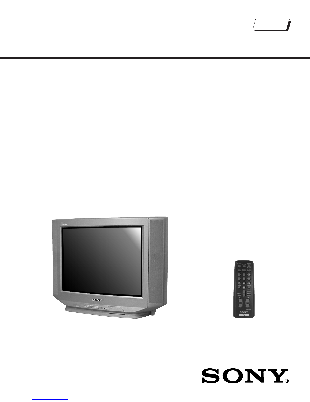
Self Diagnosis
Supported model
SERVICE MANUAL
MODEL NAME REMOTE COMMANDER DESTINATION CHASSIS NO.
KV-20S90
RM-Y155 US SCC-S27NA
BA-4D
CHASSIS
Trinitron
KV-20S90
RM-Y155
TRINITRON® COLOR TELEVISION
9-965-905-01
Page 2
SECTION 4: CIRCUIT ADJUSTMENTS
ELECTRICAL ADJUSTMENTS BY REMOTE COMMANDER
Use the Remote Commander (RM-Y155) to perform the circuit adjustments in this section.
Test Equipment Required: 1. Pattern generator 2. Frequency counter 3. Digital multimeter 4. Audio oscillator
KV-20S90 / 21SE43C
4-1. SETTING THE SERVICE ADJUSTMENT
MODE
1. Standby mode (Power off).
2. Press the following buttons on the remote commander within a
second of each other:
Display
Channel 5 Sound Volumne + Power
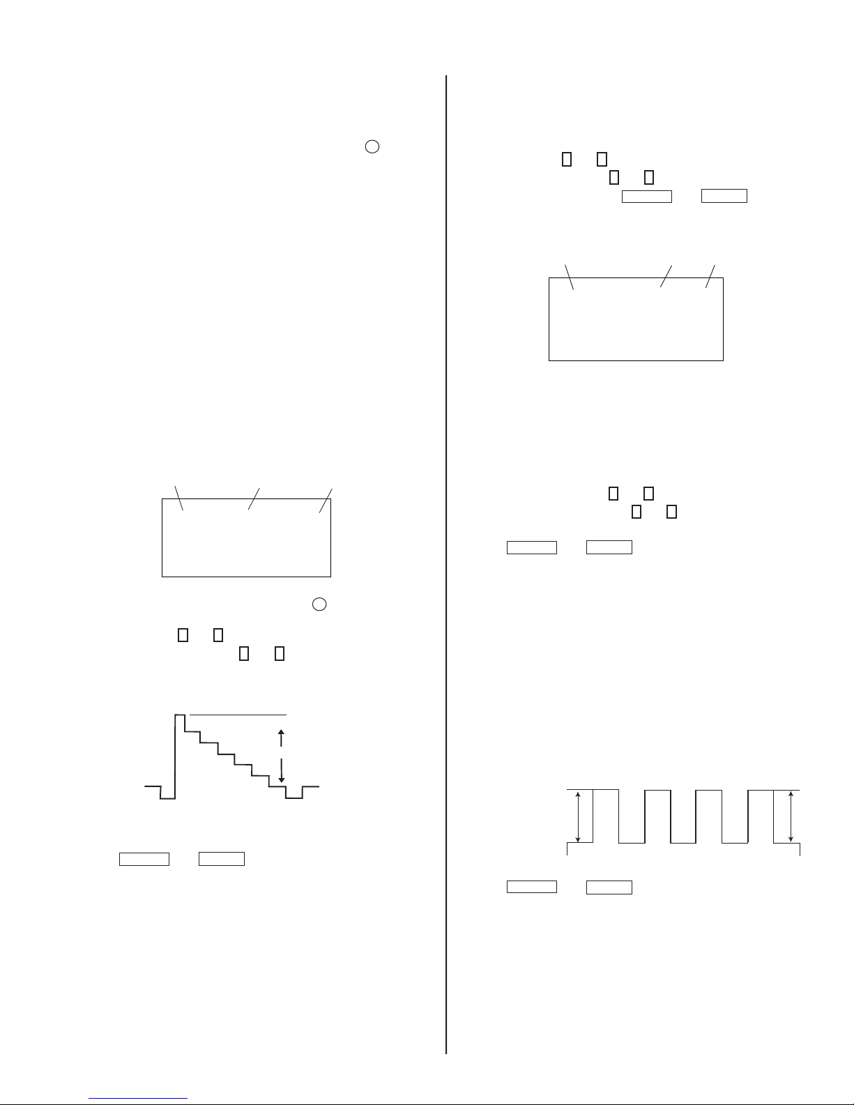
SERVICE ADJUSTMENT MODE ON
1. The CRT displays the item being adjusted.
Item
Data
0
to write into memory.
2. Press
3. Press
4. Press
then
Display
Item
HSIZ
ENTER
Mode
SERVICE
1
or 4 on the Remote Commander to select the item.
3
or 6 on the Remote Commander to change the data.
MUTING
SERVICE ADJUSTMENT MODE MEMORY
Mode
1. Press
SERVICE
8
then
ENTER
MUTING
WRITE
ENTER
on the Remote Commander to initialize.
Green
Red
4-2. MEMORY WRITE CONFIRMATION
METHOD
1. After adjustment, pull out the plug from the AC outlet, then replace
the plug in the AC outlet again.
2. Turn the power switch ON and set to Service Mode.
3. Call the adjusted items again to confi rm they were adjusted.
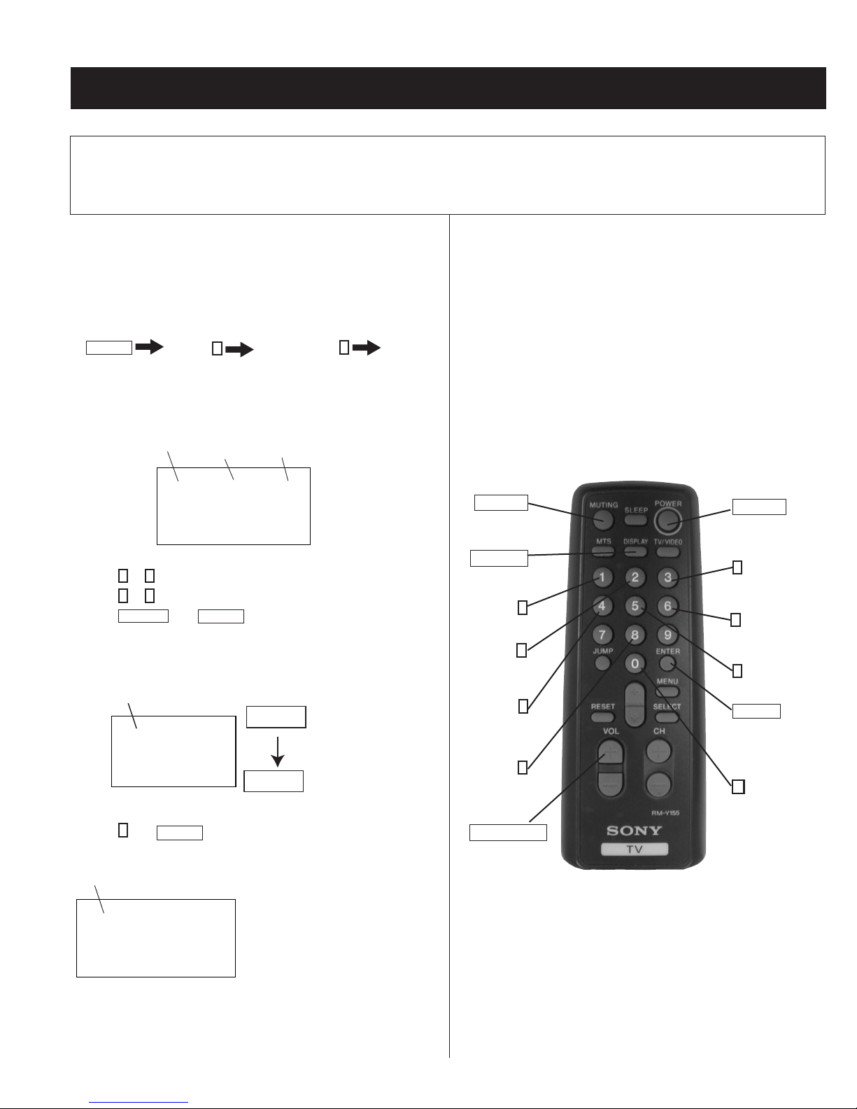
4-3. REMOTE ADJUSTMENT BUTTONS AND
INDICATORS
MUTING
(Enter into
memory)
DISPLAY
(Service Mode)
1
Disp. (Item up)
2
(Device Item Up)
4
Disp. (Item down)
8
(Initialize)
VOLUME (+)
(Service Mode)
POWER
(Service Mode)
3
Item (Data up)
6
Item (Data down)
5
(Device item down)
ENTER
(Enter into
memory)
0
(Remove from
memory)
Mode
SERVICE RESET
2. Turn set off then on to exit service adjustment mode.
Carry out Step 1 when adjusting
IDs 0-7 and when replacing and
adjusting IC003
RM-Y155
— 16 —
Page 3
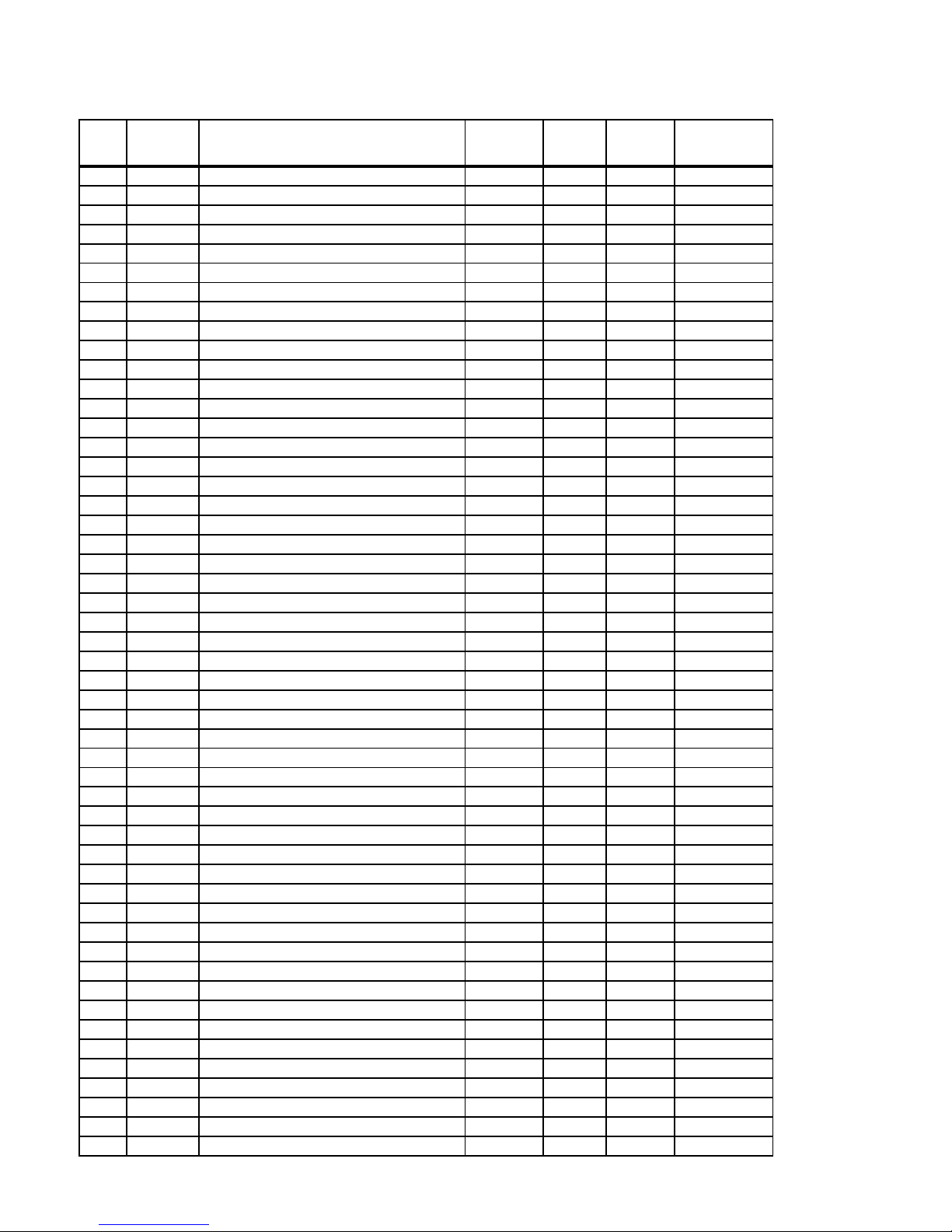
ADJUSTMENT ITEMS (1 OF 2)
KV-20S90 / 21SE43C
DATA
Reg # ITEM FUNCTION
1 HSIZ Horizontal Amp. Adjustment 0-31 31 31
2 HPOS Horizontal Position Adjustment 0-31 21 20
3 VBOW Vertical Line Bowing Adj. 0-15 6 6
4 VANG Vertical line Bowing Slant Adj. 0-15 6 6
5 TRAP Horizontal Trapezoid Adj. 0-15 15 15
6 PAMP Horizontal PIN Distortion Adj. 0-31 31 31
7 CPIN SAME AS PAMP-SCRN TP/BTM 0-31 31 31
8 VSIZ Vertical Amp. Adjustment 0-31 43 37
9 VPOS Vertical Position Adj. 0-31 35 38
10 VLIN Vertical Linearity Adj. 0-15 7 7
11 SCOR Vertical Amount Adj. 0-15 7 7
12 VZOM Vertical Zooming 0,1 0 0
13 EHT Vertical High-Voltage Correction 0-15 15 4
14 ASP Aspect Ratio Control 0-63 47 47
15 SCRL 16:9 CRT Z Mode Trans. Scroll 0-31 31 31
16 HBLK RGB Out Width Control 0,1 1 1
17 LBLK Left Screen HBLK Control 0-15 15 15
18 RBLK RGT Screen HBLK Control 0-15 3 3
19 VUSN V Saw Waveform Compress 0,1 0 0
20 HDW Horizontal Drive Pulse Width 0,1 1 0
21 EWDC EW/ D.C. Adjustment 0,1 0 0
22 LVLN Lower Screen BTM Vertical Line Adj. 0-15 0 0
23 UVLN Upper Screen Top Vertical Line Adj. 0-15 0 0
24 RDRV R Output Drive Control 0-31 30 27
25 GDRV G Output Drive Control 0-31 24 22
26 BDRV B Output Drive Control 0-31 21 22
27 RCUT R Output Cutoff Control 0-15 10 9
28 GCUT G Output Cutoff Control 0-15 7 4
29 BCUT B Output Cutoff Control 0-15 7 4
30 DCOL Dynamic Color On/Off 0,1 0 0
31 SHUE Sub HUE 0-15 15 18
32 SCOL Sub Color 0-15 14 18
33 SBRT Sub BRIGHTNESS 0-15 7 10
34 RON R Output On/Off 0,1 1 1
35 GON G Output On/Off 0,1 1 1
36 BON B Output On/Off 0,1 1 1
37 AXPL Axis PAL 0,1 0 0
38 AXNT Axis NTSC 6.00 ± 0.8 0 0
39 CBPF Chroma BPF On/Off 0,1 1 1
40 CTRP Y TRAP FILTER On/Off 6.00 ± 0.9 0 1
41 COFF Color On/Off 0,1 0 0
42 KOFF Set Color Killer 6.00 ± 0.8 0 0
43 SSHP Sub SHARPNESS 0-15 9 6
44 SHPF SHARPNESS Circuit Fo 0,1 1 1 *
45 PREL Pre-Shoot / Over-Shoot Switching 0,1 1 1
46 Y-DC Axis NTSC 0,1 1 1
47 GAMM Chroma BPF On/Off 0,1 0 0
48 VTH Color On/Off 0,1 1 1
49 ABLM ABL Control Mode 0,1 1 1
50 YDEL Set Color Killer 0,1 7 7
51 NCOL Sub Sharpness 0-15 1 1
RANGE
INITIAL
DATA VIDEO
AVERAGE
* = TV/VIDEO = 0
DATA
— 17 —
Page 4
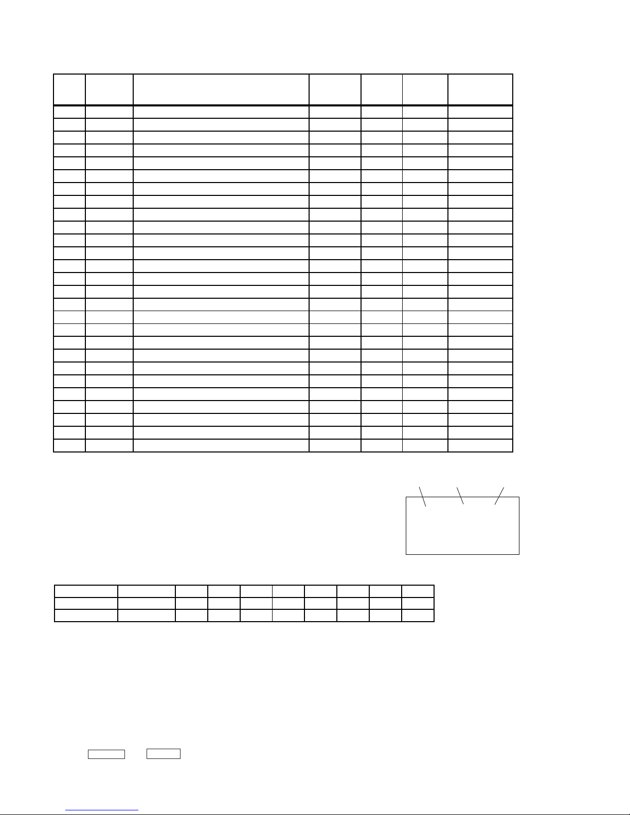
ADJUSTMENT ITEMS (2 OF 2)
KV-20S90 / 21SE43C
DATA
Reg # ITEM FUNCTION
52 FSC G Output On/Off 0,1 0 1
53 K-ID B Output On/Off 0,1 0 0
54 HOSC Horizontal VCO Oscillation Freq. 0-15 10 7
55 VSS Vertical Sync Slice Level 0,1 0 0
56 HSS Horizontal Sync Slice Level 0,1 0 0
57 HMSK HMASK On/Off 0,1 1 1
58 VTMS Select Signal VTIM Pin 0-3 0 0
59 CDMD Vertical Count Down Mode Switching 0-3 3 3 **
60 AFC AFC Loop Gain Switching 0-3 0 0 *
61 FIFR Field Frequency 0-3 3 3
62 SBAS Sub Bass 0-15 8 8
63 STRE Sub Treble 0-15 9 9
64 SBAL Sub Balance 0-15 13 13
65 DISP O.S.D Display Position 0-127 15 5
66 PADJ POWER ADJUSTMENT 0-63 51 42
67 HCHM H SYNCH SEP. LIMIT FOR TUNER 0-127 69 69
68 HCLM H SYNCH SEP. LIMIT FOR TUNER 0-127 16 16
69 HCHS H SYNCH SEP. LIMIT FOR VIDEO 0-127 69 69
70 HCLS H SYNCH SEP. LIMIT FOR VIDEO 0-127 16 16
71 ID0 0-255 SEE ID MAP
72 ID1 0-255 SEE ID MAP
73 ID2 0-255 SEE ID MAP
74 ID3 0-255 SEE ID MAP
75 ID4 0-255 SEE ID MAP
76 ID5 0-255 SEE ID MAP
77 ID6 0-255 SEE ID MAP
78 ID7 0-255 SEE ID MAP
RANGE
INITIAL
DATA VIDEO
AVERAGE
DATA
* = TV/VIDEO = 0
** = TV = 0, VIDEO = 1
Notes:
Mode
No. 1-78 show the order that each adjustment mode may be selected while in Service Mode.
Data Range shows the range of possible setting for each Adjustment Mode.
Initial Data shows the standard settings for each Adjustment Mode.
Function
SERVICE
ID0 25
Data
ID MAP
Model Destination ID-0 ID-1 ID-2 ID-3 ID-4 ID-5 ID-6 ID-7
KV-20S90 US 25 3 1 227 3100
KV-21SE43C E 17 3 1 195 115 1 0 0
4-4. A BOARD ADJUSTMENTS
H. FREQUENCY ADJUSTMENT
1. InputTV mode (RF) with no signal.
2. Set to Service Adjustment Mode.
3. Connect a frequency counter to base of Q501
(TP-500 H. DRIVE).
4. Check H. Frequency for 15735 ± 200 Hz.
5. Press
MUTING
then
ENTER
to save into the memory.
— 18 —
Page 5
V. FREQUENCY CHECK
1. Select video 1 with no signal input.
2. Set the conditions for a standard setting.
3. Connect the frequency counter to TP-508 or CN501 pin
6
connector and ground.
4. Check that V. Frequency shows 60 ± 4 Hz.
SUB CONTRAST ADJUSTMENT (RDRV)
(V DY+)
KV-20S90 / 21SE43C
DISPLAY POSITION ADJUSTMENT (DISP)
1. Input a color-bar signal.
2. Set to Service Adjustment Mode.
3. Select DISP with
4. Adjust values of DISP with
5. Write to memory by pressing
6. Check to see if the text is displayed on the screen.
1
and 4 .
3
and 6 to adjust characters to the center.
MUTING
then
ENTER
.
1. Input a color-bar signal.
2. Set the red color on (1).
3. Set in Service Adjustment Mode.
4. Select the item DCOL level to 0.
5. Set the conditions as follows:
PICTURE: MAX
COLOR: MIN
BRIGHT: CENTER
R ON: ON (1)
G ON: OFF (0)
B ON: OFF (0)
Mode
SERVICE
Display
Item
RON
6. Connect an oscilloscope probe to CN301 pin
1: ON
0: OFF
26
2
ground .
1
7. Select RDRV with
8. Adjust the value of RDRV with
and 4 .
3
and 6 for
1.50 ± 0.05 Vpp.
White
1.50 ± 0.05 Vpp
(Red Out) and
Mode
SERVICE DISP 15
Display
Item
Item
Data
SUB BRIGHT ADJUSTMENT (SBRT)
1. Input a crosshatch signal.
2. Set to Service Adjustment Mode.
3. Set the PICTURE and BRIGHTNESS to minimum.
4. Select the SBRT item with
5. Adjust the values of SBRT with
1
and 4 .
3
and 6 to obtain a faintly visible
crosshatch.
6. Press
MUTING
then
ENTER
to save into the memory.
SUB HUE, SUB COLOR ADJUSTMENT (SHUE,
SCOL)
1. Input a color-bar signal.
2. Set to Service Adjustment Mode.
3. Connect a probe to TP47B B-OUT (C Board).
4. Measure white V1 and blue V4.
4.1) Increase SCOL Register +1 setp.
Black
9. Reset the item DCOL to 1.
10. Press
MUTING
then
ENTER
11. Return the following back to normal after adjustment.
PICTURE: MAX
COLOR: CENTER
BRIGHT: CENTER
R ON: ON (1)
G ON: OFF (1)
B ON: OFF (1)
to save into the memory.
5. Press
— 19 —
STANDARD
|V4 - V1| = ± 0.2Vpp
|V3 - V2| = ± 0.2Vpp
MUTING
then
V1
ENTER
V2 V3
to save into the memory.
V4
Page 6
KV-20S90 / 21SE43C
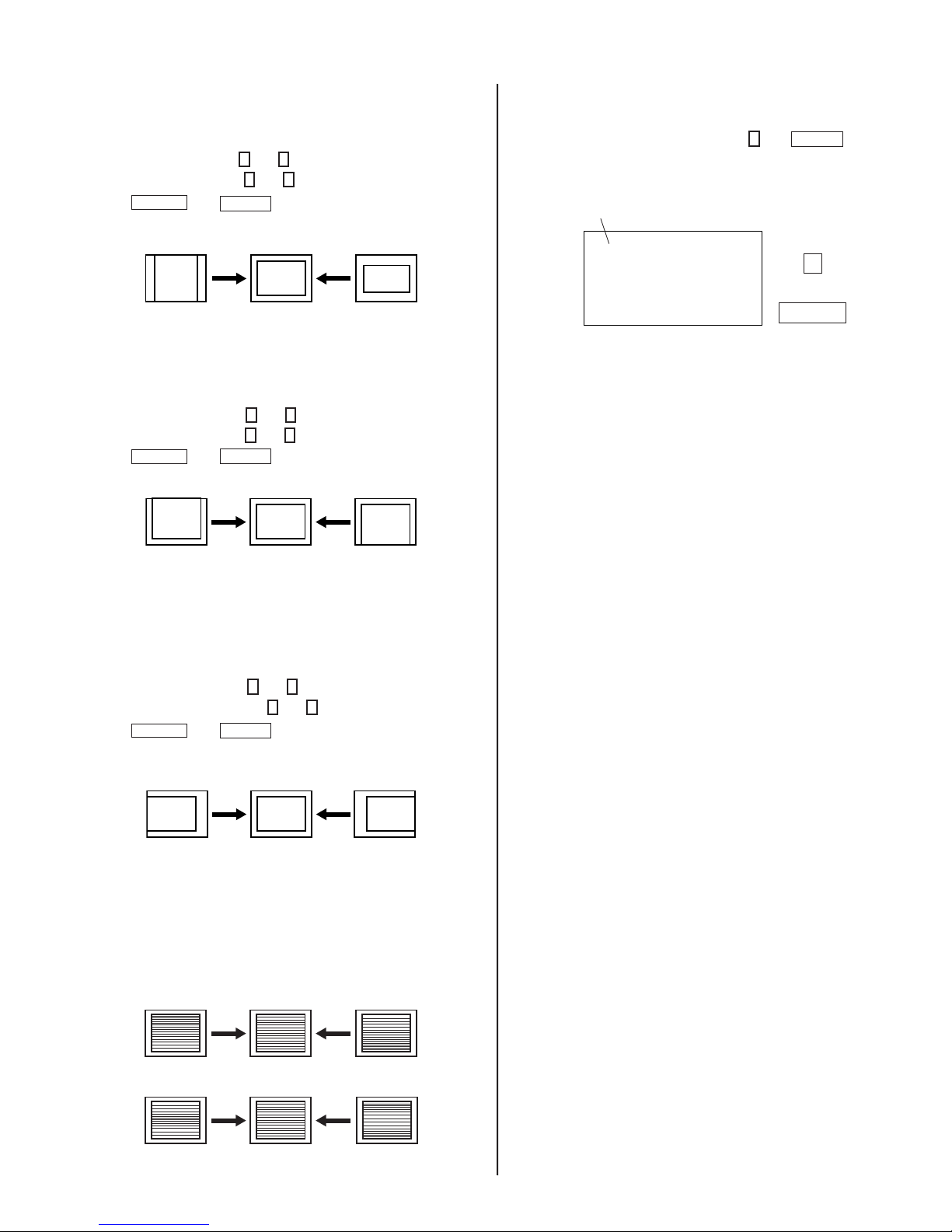
V. SIZE ADJUSTMENT (VSIZ)
1. Input a crosshatch signal.
2. Activate the Service Adjustment Mode.
3. Select the VSIZ item with
4. Adjust value of VPOS with
5. Press
MUTING
then
1
and 4 .
1
and 4 for the best vertical center.
ENTER
to save into the memory.
V. CENTER ADJUSTMENT (VPOS)
1. Input a crosshatch signal.
2. Set to Service Adjustment Mode.
3. Select the VPOS item with
4. Adjust value of VPOS with
5. Press
MUTING
then
1
and 4 .
3
and 6 for the best vertical center.
ENTER
to save into the memory.
SERVICE ADJUSTMENT MODE MEMORY
1. Change the value of the DCOL item to 1.
ENTER
0
2. After completing all adjustments, press
Read From Memory
Mode
SERVICE READ
then
.
Green
0
Red
ENTER
H. CENTER ADJUSTMENT (HPOS)
Perform this adjustment after performing H. Frequency.
1. Input a crosshatch signal.
2. Set to Service Adjustment Mode.
3. Select the HPOS item with
4. Adjust the value of HPOS with
5. Press
MUTING
then
1
and 4 .
ENTER
3
and 6 for the best horizontal center.
to save into the memory.
V. LINEARITY (VLIN), V. CORRECTION
1. Input a crosshatch signal.
2. V.Correction is automatically adjusted from the circuit and should
satisfy the conditions below.
V LINEARITY (VLIN)
V CORRECTION
— 20 —
 Loading...