

Page 1
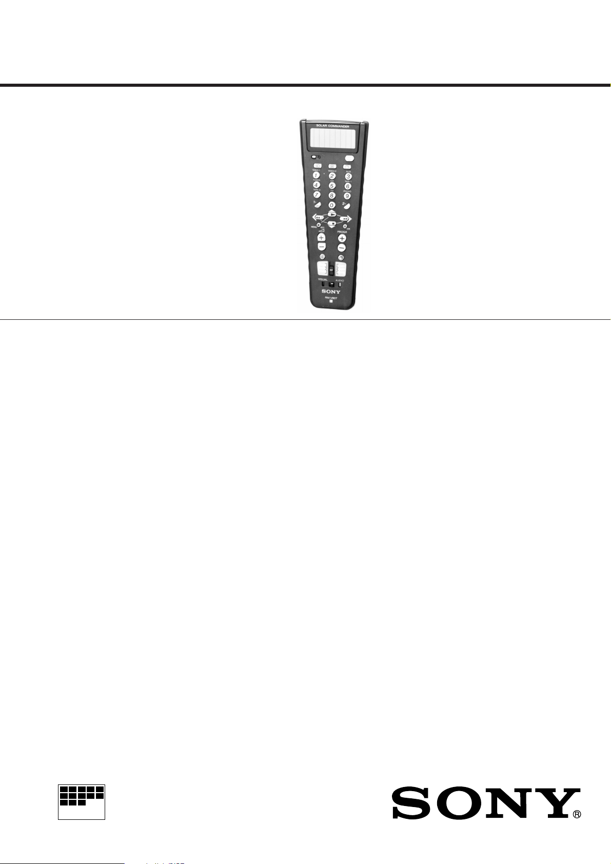
RM-V80T
SERVICE MANUAL
Ver . 1.0 1998.03
SPECIFICATIONS
Operable distance
Approx. 7m (23 ft) (varies depending on the component of
each manufacturer)
Power requirements
Vanadium-Lithium Rechargeable Battery (3.0 V, 50 mAh)
Flexible Hydrogenated Amorphous Silicon Solar Cells
Dimensions
Approx. 74 x 210 x 25 mm (w/h/d)
(3 x 8 x 1 in.)
Mass Approx. 150 g (5 oz.)
Supplied accessory
Label (1)
AEP Model
Design and specifications are subject to change without notice.
REMOTE COMMANDER
MICROFILM
Page 2
SECTION 1
GENERAL
This section is extracted from
instruction manual.
– 2 –
Page 3

– 3 –
Page 4

4.6Vp-p
4MHz
RM-V80T
2-1. SCHEMATIC DIAGRAM
SECTION 2
DIAGRAMS
Note:
• All capacitors are in µF unless otherwise noted. pF: µµF
50 WV or less are not indicated except for electrolytics
and tantalums.
• All resistors are in Ω and 1/
specified.
¢
•
• U : B+ Line.
• Power voltage is dc 3V and fed with regulated dc power
• Voltages and waveforms are dc with respect to ground
• Voltages are taken with a VOM (Input impedance 10 MΩ).
• Waveforms are taken with a oscilloscope.
• Circled numbers refer to waveforms.
: internal component.
supply from battery terminal.
under no-signal conditions.
Voltage variations may be noted due to normal production tolerances.
Voltage variations may be noted due to normal production tolerances.
: Impossible to measure
∗
4
W or less unless otherwise
r
WA V0EFORM
1
VOLT/DIV : 1V AC
TIME/DIV : 0.1 µ sec
– 4 –
Page 5

Page 6

SECTION 3
EXPLODED VIEW
RM-V80T
CONTROL
SECTION 4
ELECTRICAL PARTS LIST
NOTE :
• -XX, -X mean standardized parts, so they
may have some difference from the original
one.
• Items marked “ * ”are not stocked since they
are seldom required for routine service. Some
delay should be anticipated when ordering
these items.
6
5
4
3
2
1
BT1
• The mechanical parts with no reference
number in the exploded views are not
supplied.
• Accessories and packing materials are given
in the last of this parts list.
7
8
9
17
SL1
16
17
15
14
12
13
17
11
17
not supplied
10
11
17
NOTE :
• Due to standardization, replacements in the
parts list may be different from the parts
specified in the diagrams or the components
used on the set.
• -XX, -X mean standardized parts, so they
may have some difference from the original
one.
• RESISTORS
All resistors are in ohms
METAL : Metal-film resistor
METAL OXIDE :Metal oxide-film resistor
F : nonflammable
• Items marked “ * ”are not stocked since
they are seldom required for routine service.
Some delay should be anticipated when
ordering these items.
Ref. No. Part No. Description Remark Ref. No. Part No. Description Remark
* A-4542-498-A CONTROL BOARD, COMPLETE
*************************
4-999-266-01 RETAINER, SOLAR
< BATTERY>
BT1 1-528-886-11 BATTERY
SL1 1-528-885-11 BATTERY
< CAPACITOR >
C2 1-126-382-11 ELECT 100uF 20% 6.3V
C3 1-126-923-11 ELECT 220uF 20% 10V
< DIODE >
D1 8-719-053-71 DIODE SID1K10CM
D2 8-719-912-39 DIODE SLR932A
D3 8-719-023-22 DIODE MA704A
< IC >
IC1 8-759-531-56 IC MN9807SC-E1
IC2 8-759-534-18 IC S-81237SGUP
< COIL >
• SEMICONDUCTORS
In each case, u : µ , for example :
uA.... : µ A.... , uPA.... : µ PA....
uPB.... : µ PB.... , uPC.... : µ PC....
uPD.... : µ PD....
• CAPACITORS
uF : µ F
• COILS
uH : µ H
(REMOTE CONTROL SENSOR)
(REMOTE CONTROL SENSOR)
When indicating parts by reference number, please include the board.
< VIBRATOR >
X1 1-577-082-11 VIBRATOR, CERAMIC (4MHz)
************************************************************
MISCELLANEOUS
***************
BT1 1-528-886-11 BATTERY (3V)
SL1 1-528-885-11 BATTERY
************************************************************
ACCESSORIES & PACKING MATERIALS
********************************
3-862-476-11 INSTRUCTION (MAKER CORD LIST)
3-862-649-11 MANUAL, INSTRUCTION (ENGLISH, FRENCH)
3-862-649-21 MANUAL, INSTRUCTION (GERMAN, SPANISH)
3-862-649-31 MANUAL, INSTRUCTION (ITALIAN,
PORTUGUESE)
3-862-649-41 MANUAL, INSTRUCTION (DUTCH, SWEDISH)
3-862-649-51 MANUAL, INSTRUCTION (FINNISH, RUSSIAN)
Ref. No. Part No. Description Remark Ref. No. Part No. Description Remark
* 1 A-4542-498-A CONTROL BOARD, COMPLETE
2 4-999-272-01 SHEET, RUBBER
* 3 4-999-274-01 CUSHION (SIDE)
4 4-999-263-01 KNOB (B), SWITCH
5 4-999-262-01 KNOB (A), SWITCH
6 4-999-270-01 CASE (UPPER)
7 4-999-267-01 COVER, SOLAR
* 8 4-999-328-01 SHEET (A), ADHESIVE
9 4-999-269-01 FILTER
* 10 4-999-273-01 CUSHION (UNDER)
11 4-999-265-01 FOOT, RUBBER
12 4-999-271-01 CASE (LOWER)
* 13 4-999-507-01 HOLDER, BATTERY
14 4-999-264-01 KNOB (C), SWITCH
15 4-999-266-01 RETAINER, SOLAR
* 16 4-999-329-01 SHEET (B), ADHESIVE
17 7-685-104-19 SCREW +P 2X6 TYPE2 NON-SLIT
BT1 1-528-886-11 BATTERY (3V)
SL1 1-528-885-11 BATTERY
– 7 –
L1 1-469-104-11 COIL 150uH
< TRANSISTOR >
Q1 8-729-140-75 TRANSISTOR 2SD999-CLCK
< RESISTOR >
R1 1-216-182-00 RES,CHIP 220 5% 1/8W
R2 1-216-181-11 RES,CHIP 200 5% 1/8W
< SWITCH >
SW1 1-553-510-11 SWITCH, SLIDE (ON c)
SW2 1-572-487-21 SWITCH, SLIDE (AMP/TAPE/AUX2/CD,
SW3 1-570-397-11 SWITCH, SLIDE (AUDIO/VISUAL)
TV/SAT/AUX 1/VCR)
Sony Corporation
9-923-327-11
Personal A&V Products Company
– 8 –
Printed in Japan © 1998.3
98C0239-1
Published by Quality Engineering Dept.
(Shibaura)
 Loading...