

Page 1

4-177-133-12 (1)
Remote Control Unit
Operating Instructions
Before operating the unit, please read this manual thoroughly
and retain it for future reference.
RMU-01
© 2010 Sony Corporation
Page 2

WARNING
To reduce the risk of fire or
electric shock, do not expose
this apparatus to rain or
moisture.
To avoid electrical shock, do not
open the cabinet. Refer
servicing to qualified personnel
only.
CAUTION for LAN port
For safety reason, do not connect the LAN
port to any network devices that might have
excessive voltage.
The LAN port of this unit is to be connected
only to the devices whose power feeding
meets the requirements for SELV (Safety
Extra Low Voltage) and complies with
Limited Power Source according to IEC
60950-1.
For the customers in the U.S.A.
This equipment has been tested and found
to comply with the limits for a Class B
digital device, pursuant to Part 15 of the
FCC Rules. These limits are designed to
provide reasonable protection against
harmful interference in a residential
installation. This equipment generates,
uses, and can radiate radio frequency
energy and, if not installed and used in
accordance with the instructions, may cause
harmful interference to radio
communications. However, there is no
guarantee that interference will not occur in
a particular installation. If this equipment
does cause harmful interference to radio or
television reception, which can be
determined by turning the equipment off
and on, the user is encouraged to try to
correct the interference by one or more of
the following measures:
-Reorient or relocate the receiving
antenna.
- Increase the separation between the
equipment and receiver.
- Connect the equipment into an outlet on
a circuit different from that to which the
receiver is connected.
- Consult the dealer or an experienced
radio/TV technician for help.
You are cautioned that any changes or
modifications not expressly approved in
this manual could void your authority to
operate this equipment.
If you have any questions about this
product, you may call;
Sony Customer Information Service Center
1-800-222-7669 or
http://www.sony.com/
Declaration of Conformity
Trade Name: SONY
Model: RMU-01
Responsible Party: Sony Electronics
Inc.
Address: 16530 Via Esprillo, San
Diego, CA 92127 U.S.A.
Telephone Number: 858-942-2230
This device complies with part 15 of the
FCC Rules. Operation is subject to the
following two conditions: (1) this device
may not cause harmful interference,
and (2) this device must accept any
interference received, including
interference that may cause undesired
operation.
For the customers in Canada
This Class B digital apparatus complies
with Canadian ICES-003.
Operation is subject to the following two
conditions: (1) this device may not cause
interference, and (2) this device must accept
any interference, including interference that
may cause undesired operation of the
device.
2
Page 3

The term “IC:” before the radio certification
number only signifies that Industry Canada
technical specifications were met.
This model has an RF module of the
FCC/IC approval built-in.
BUILT IN MODULE RM-223
FCC-ID: AK8RM223
IC: 409B-RM223
For the customers in the U.S.A.
IMPORTANT NOTE: To comply with the
FCC RF exposure compliance
requirements, no change to the antenna or
the device is permitted,
Any change to the antenna or the device
could result in the device exceeding the RF
exposure requirements and void user’s
authority to operate this device.
This device complies with FCC radiation
exposure limits set forth for uncontrolled
equipment and meets the FCC radio
frequency (RF) Exposure Guidelines in
Supplement C to OET65. This device has
very low levels of RF energy that it is
deemed to comply without testing of
specific absorption radio (SAR).
This device complies with Part 15 of the
FCC Rules. Operation is subject to the
following two conditions: (1) this device
may not cause harmful interference, and (2)
this device must accept any interference
received, including interference that may
cause undesired operation.
For the customers in Europe
Hereby, Sony Corporation, declares that
this RMU-01 is in compliance with the
essential requirements and other relevant
provisions of the Directive 1999/5/EC.
For details, please access the following
URL: http://www.compliance.sony.de/
This product is intended to be used in the
following countries : United Kingdom,
Germany, Norway, Luxembourg, Belgium,
Denmark, France, Italy, Sweden,
Switzerland, Finland, Iceland, and Turkey.
Voor de klanten in Europa
Hierbij verklaart Sony Corporation dat het
toestel RMU-01 in overeenstemming is met
de essentiële eisen en de andere relevante
bepalingen van richtlijn 1999/5/EG.
Nadere informatie kunt u vinden op:
http://www.compliance.sony.de/
Dit product is bedoeld om in volgende
landen gebruikt te worden: Verenigd
Koninkrijk, Duitsland, Noorwegen,
Luxemburg, België, Denemarken,
Frankrijk, Italië, Zweden, Zwitserland,
Finland, IJsland en Turkije.
For kunder i Europa
Härmed intygar Sony Corporation att denna
RMU-01 står I överensstämmelse med de
väsentliga egenskapskrav och övriga
relevanta bestämmelser som framgår av
direktiv 1999/5/EG.
För ytterligare information gå in på följande
hemsida: http://www.compliance.sony.de/
Den här produkten är avsedd för
användning i följande länder:
Storbritannien, Tyskland, Norge,
Luxembourg, Belgien, Danmark,
Frankrike, Italien, Sverige, Schweiz,
Finland, Island och Turkiet.
Para os clientes da Europa
Sony Corporation declara que este RMU-01
está conforme com os requisitos essenciais
e outras disposições da Directiva 1999/5/
CE.
Para mais informacoes, por favor consulte a
seguinte URL:
http://www.compliance.sony.de/
Este produto destina-se a ser usado nos
seguintes países: Reino Unido, Alemanha,
Noruega, Luxemburgo, Bélgica,
Dinamarca, França, Itália, Suécia, Suíça,
Finlândia, Islândia e Turquia.
3
Page 4
For kunder i Europa
Undertegnede Sony Corporation erklærer
herved, at følgende udstyr RMU-01
overholder de væsentlige krav og øvrige
relevante krav i direktiv 1999/5/EF.
For yderligere information gå ind på
følgende hjemmeside:
http://www.compliance.sony.de/
Dette produkt er beregnet til brug i de
følgende lande: Storbritannien, Tyskland,
Norge, Luxembourg, Belgien, Danmark,
Frankrig, Italien, Sverige, Schweiz,
Finland, Island og Tyrkiet.
Euroopassa oleville asiakkaille
Sony Corporation vakuuttaa täten että
RMU-01 tyyppinen laite on direktiivin
1999/5/EY oleellisten vaatimusten ja sitä
koskevien direktiivin muiden ehtojen
mukainen.
Halutessasi lisätietoja, käy osoitteessa:
http://www.compliance.sony.de/
Tämä tuote on tarkoitettu käytettäväksi
seuraavissa maissa: Yhdistynyt
kuningaskunta, Saksa, Norja, Luxemburg,
Belgia, Tanska, Ranska, Italia, Ruotsi,
Sveitsi, Suomi, Islanti ja Turkki.
For kundene i Europa
Sony Corporation erklærer herved at
utstyret RMU-01 er i samsvar med de
grunnleggende krav og øvrige relevante
krav i direktiv 1999/5/EF.
For flere detaljer, vennligst se:
http://www.compliance.sony.de/
Dette produktet er ment for bruk i følgende
land: Storbritannia, Tyskland, Norge,
Luxemburg, Belgia, Danmark, Frankrike,
Italia, Sverige, Sveits, Finland, Island og
Tyrkia.
Για τους πελάτες στην Eυρώπη
Με την παρούσα η Sony Corporation
δηλώνει τι RMU-01
συμμορφώνεται προς της ουσιώδεις
απαιτήσεις και τις λοιπές σχετικές
διατάξεις της οδηγίας 1999/5/ΕΚ..
Για λεπτομέρειες παρακαλούμε
πως ελένξετε την ακλουθη
σελίδα του διαδικτύου:
http://www.compliance.sony.de/
Το προϊν προορίζεται για χρήση
στις εξής χώρες: Ηνωμένο Βασίλειο,
Γερμανία, Νορβηγία,
Λουξεμβούργο, Βέλγιο, Δανία,
Γαλλία, Ιταλία, Σουηδία, Ελβετία,
Φινλανδία, Ισλανδία και Τουρκία.
Pro zákazníky v Evropě
Sony Corporation tímto prohlašuje, že
tento RMU-01 je ve shodě se základními
požadavky a dalšími příslušnými
ustanoveními směrnice 1999/5/ES.
Podrobnosti lze získat na následující
URL:
http://www.compliance.sony.de/
Tento produkt je určen k použití v
následujících zemích: Spojené
království, Německo, Norsko,
Lucembursko, Belgie, Dánsko, Francie,
Itálie, Švédsko, Švýcarsko, Finsko,
Island a Turecko.
Euroopa klientidele
Sony Corporation kinnitab käesolevaga
seadme RMU-01 vastavust 1999/5/EÜ
direktiivi põhinõuetele ja nimetatud
4
Page 5
direktiivist tulenevatele teistele
asjakohastele sätetele.
Üksikasjalikum info:
http://www.compliance.sony.de/.
See toode on ettenähtud kasutamiseks
järgmistes riikides: Suurbritannia,
Saksamaa, Norra, Luksemburg, Belgia,
Taani, Prantsusmaa, Itaalia, Rootsi, Šveits,
Soome, Island ja Türgi.
Európai vásárlóink fi gyelmébe
Alulírott, Sony Corporation
nyilatkozom, hogy a(z) RMU-01
megfelel a vonatkozó alapvető
követelményeknek és az 1999/5/EC
irányelv egyéb előírásainak.
További információkat a következő
weboldalon találhat:
http://www.compliance.sony.de/
Ez a termék a következő országokban
használható: Egyesült Királyság,
Németország, Norvégia, Luxemburg,
Belgium, Dánia, Franciaország,
Olaszország, Svédország, Svájc,
Finnország, Izland és Törökország.
Dotyczy klientów z Europy
Niniejszym Sony Corporation
oświadcza, że RMU-01 jest zgodne z
zasadniczymi wymaganiami oraz innymi
stosownymi postanowieniami
Dyrektywy 1999/5/WE.
Szczegółowe informacje znaleźć można
pod następującym adresem URL:
http://www.compliance.sony.de/
Ten produkt jest przeznaczony do
użytku w następujących krajach:
Wielkiej Brytanii , Niemczech, Norwegii,
Luksemburgu, Belgii, Danii, Francji,
Włoszech, Szwecji, Szwajcarii, Finlandii,
Islandii i Turcji.
Pentru clienţii din Europa
Prin prezenta, Sony Corporation declară
că acest RMU-01 respectă cerinţele
esenţiale și este în conformitate cu
prevederile Directivei 1995/5/EC.
Pentru detalii, vă rugăm accesaţi
următoarea adresă:
http://www.compliance.sony.de/
Acest produs este destinat utilizării în
următoarele ţări: Regatul Unit,
Germania, Norvegia, Luxemburg,
Belgia, Danemarca, Franţa, Italia,
Suedia, Elveţia, Finlanda, Islanda și
Turcia.
Pre zákazníkov v Európe
Sony Corporation týmto vyhlasuje, že
RMU-01 spĺňa základné požiadavky a
všetky príslušné ustanovenia Smernice
1999/5/ES.
Podrobnosti získate na nasledovnej
webovej adrese:
http://www.compliance.sony.de/
5
Page 6

Tento produkt je určený na používanie v
nasledovných krajinách: Veľká
Británia, Nemecko, Nórsko,
Luxembursko, Belgicko, Dánsko,
Francúzsko, Taliansko, Švédsko,
Švajčiarsko, Fínsko, Island a Turecko.
Za stranke v Evropi
Sony Corporation izjavlja, da je ta
RMU-01 v skladu z bistvenimi
zahtevami in ostalimi relevantnimi
določili direktive 1999/5/ES.
Za podrobnosti vas naprošamo, če
pogledate naURL:
http://www.compliance.sony.de/
Izdelek je namenjen za uporabo v
naslednjih državah: Veliki Britaniji,
Nemčiji, Norveški, Luksemburgu,
Belgiji, Danski, Franciji, Italiji, Švedski,
Švici, Finski, Islandiji in Turčiji.
6
Page 7

Table of Contents
Overview .........................................8
Parts Identifications .......................9
Making Use of the NT Remote
Function .........................................10
Installations ...................................13
Attaching to the Microphone
Stand .......................................13
Attaching on the Wall .............14
Attaching to the Catwalk, Pole, or
a Lighting Battens ..................15
Preparations of Operation ...........16
Using the RMU-01 Setting
Tool ................................................16
Preparations ............................17
Starting Up and Exiting the
Software ..................................18
Parts Identification .................18
Detecting the RMU-01 Units on
the Network Automatically ....19
Changing Settings of the
RMU-01 ..................................19
Additional Functions ..............20
Connecting to Power Supply and
Other Devices ................................22
Supplying Power From the PoE
Device .....................................22
Supplying Power From the AC
Adapter ...................................23
Troubleshooting............................ 24
On the Status of This Unit and the
Lighting Status of the POWER
Indicator ..................................25
Important Notes on Operation .... 26
On Power Supply ....................26
On Installation ........................26
On Operation ..........................26
On Using and Storing
Environment ........................... 26
On Cleaning ........................... 26
Specifications ................................ 27
Table of Contents
7
Page 8

Overview
The RMU-01 Remote Control Unit can be
used for a network remote control (referred
to as “NT remote,” hereafter) of the Sony
wireless microphone system.
• By connecting this unit through the LAN
cable and placing at appropriate location,
the transmitters can be controlled
remotely and the NT remote system
operation that is capable of controlling up
to 82 transmitters is highly utilized.
Up to nine RMU-01 units can be used
with one system.
• This unit accepts PoE (Power over
Ethernet) that makes long-distance LAN
connections easy. The power to this unit
can also be provided from the supplied
AC adapter.
• Inside a solid structure, a 1/4 wavelength
monopole antenna is built into this unit.
The smooth surface of this unit is
designed to match various installation
locations. This unit can easily be attached
to the microphone stand. With the
supplied brackets, this unit can also be
attached on the wall, poles, lighting
battens, catwalk, etc.
• If you plan to use a PoE hub or PoE
power supply unit, purchase it on the
market.
For details on how to connect the receivers, PoE
devices, hub, etc., refer to the operation manual
supplied with the applicable device.
What is the PoE (Power over
Ethernet)?
The PoE is a technology to supply power
through the Ethernet cable used for LAN
connection. With LAN cables carrying both
signal and power, operation in a situation
where the power supply is difficult to
reserve becomes easy.
The power can be supplied to this unit from
the connected PoE hub that conforms to
IEEE802.3af standards, or from the PoE
power supply device connected to this unit
through the hub.
Notes
• Using more of this unit in the network
system does not necessarily increase the
number of controllable transmitters. The
maximum number of controllable
transmitters in the system is 82,
regardless of the number of this unit.
For details on installation location, installation
intervals, and cables for connections, see
“Important Notes on Operation” on page 26.
Overview
8
Page 9
Parts
For details on power supply to this unit, see
“Connecting to Power Supply and Other Devices”
on page 22.
Identifications
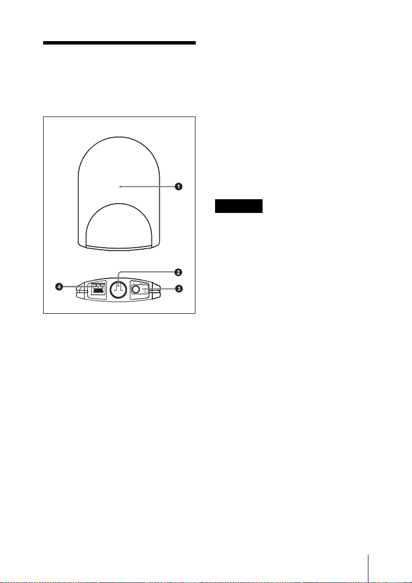
Front side
Bottom side
a Antenna storage section
b Hole for attaching the microphone
stand
Can be attached to the microphone stand
1
/2-inch thread) with this hole.
(PF
To attach an NS
microphone stand, use the supplied screw
adapter.
5
/8-inch or a W 3/8-inch
d LAN connector (RJ-45)
This is a 10Base-T/100Base-TX connector
for network connection. Communication
speed automatically changes according to
the connected device.
Connect to a receiver such as DWR-R01D,
Windows PC, or hub.
When a PoE device including PoE hub is
connected, the power is supplied through
this connector.
CAUTION
• For safety, do not connect the connector
for peripheral device wiring that might
have excessive voltage to this port.
Follow the instructions for this port.
• Do not touch the LAN connector directly
with your hand. If you do, electrostatic
discharge may damage the internal
components.
c AC adapter connector and POWER
indicator
Connect the supplied AC adapter to the AC
adapter connector to supply power to this
unit.
The POWER indicator lights up green
while the power is supplied from the AC
power connector or the LAN connector.
Parts Identifications
9
Page 10

Making Use of the NT Remote Function
To use the NT remote function fully and
with stability, note the following.
• 2.4GHz-band radiowave has the strong
tendency to travel in a straight line. When
there is an obstacle between this unit and
the transmitter, signal strength drops
rapidly. To avoid this, be sure to install
this unit so that this unit is in direct view
from where the transmitters are placed.
• In order to avoid signal interference and
to maintain stable 2.4GHz-band
transmission, it is recommended to use at
least two RMU-01 units in the network.
When installing multiple RMU-01 units,
install them so that they keep distance of
10 m to 20 m (11 yards to 22 yards) from
one another.
• Up to nine RMU-01 units can be
connected to a system. Under less
favorable environment where the signal
is weak due to signal interference,
consider adding more RMU-01 units to
reinforce the signal transmission, if
necessary.
• When operating outdoors where less
signal reflection occurs than indoors,
operating area of this unit may be
narrowed. For outdoor use, install this
unit at the same height as the transmitters
to shorten the signal transmission
distance.
• In every operating environment, the
internal antenna of this unit attains
efficient performance with the side with
connectors facing downward. However,
when this unit is installed close to the
ceiling, better performance can be
obtained by facing the front side (the side
with SONY logo) downward.
• Signal transmission status varies
depending on the structure and material
of the building where this unit is
installed. It is recommended to install this
unit so that the wireless remote control
condition level indications on the
transmitters and receivers (Shows the
quality of 2.4-GHz wireless signal. For
details, refer to the Operating
Instructions supplied with the wireless
microphone, transmitter, or the receiver.)
are stable at or .
• When the total operation area is wide by
putting together the areas that two or
more RMU-01 units cover, the
transmitter may change the RMU-01 unit
to communicate with from one to another
(roaming). Even when the areas that the
RMU-01 units cover are completely
adjacent with no gaps, the
communication between the transmitter
and the receiver is cut whenever the
roaming occurs on the transmitter. Note
that the communication is cut for several
seconds.
About the characteristics of
the built-in antenna
The antenna inside the casing of this unit
emits the strong radiowave concentrically
from the center of the antenna. Placing the
transmitter inside the radiowave circle is
important for taking advantage of the
system.
Making Use of the NT Remote Function
10
Page 11

Antenna (inside
the casing)
1) Radius: approx. 10 m (33 feet)
2) Front side (the side with SONY logo)
Emitted radiowave is strong in the area
inside the radius of approximately 10 m
(33 feet). When installing multiple RMU01 units, place them so that strong signal
area touches that of adjacent RMU-01 unit.
Installation example 1 (plane view)
When two RMU-01 units are installed to
control the body-pack transmitter that is
worn around the waist of a person, it is
recommended that the RMU-01 units be
placed across the body-pack transmitter so
that there is no obstacle between the
transmitter and at least one of the RMU-01
units.
1) RMU-01
2) Transmitter worn around the waist of a
person
Installation example 2 (plane view)
To increase the total operation area by
putting the areas that multiple RMU-01
units cover together, place them so that the
area that one RMU-01 covers touches those
on others, completely adjacent and with no
gaps.
1) RMU-01
2) Transmitter
Installation example 3 (section
view)
This is an example when this unit is
installed to the microphone stand.
Making Use of the NT Remote Function
11
Page 12

Indoors: Because the signal is reflected
from the walls, floor, and ceiling, there are
no conditions for the installation height of
this unit.
Outdoors: Install this unit at the same
height as the transmitters.
1) RMU-01
2) Transmitter
3) Wall
4) Floor
1) RMU-01
2) Transmitter
3) Floor
Installation example 4 (section
view)
This is an example when this unit is
installed on the wall.
Indoors: Because the signal is reflected
from the walls, floor, and ceiling, there are
no conditions for the installation height of
this unit.
Outdoors: Install this unit at the same
height as the transmitters.
Installation example 5 (section
view)
This is an example when this unit is
installed indoors, near the ceiling.
1) RMU-01
2) Transmitter
3) To make the most of the signal emission
characteristics, install facing the front
side (the side with SONY logo)
downward.
4) Ceiling
5) Wall
6) Floor
Making Use of the NT Remote Function
12
Page 13

Installations
Attaching to the Microphone Stand
1 Attach the cable holder to this unit.
Rear side of
this unit
Cable holder
(supplied)
Screws (supplied)
2 When attaching to an NS
3
W
/8-inch microphone stand, screw in
the supplied screw adapter into the
hole for attaching the microphone
stand.
5
/8-inch or a
Screw adapter
(supplied)
3 Insert the tip of the microphone stand
into the hole, and turn this unit to
securely attach to the microphone
stand.
Microphone stand
4 Connect the cables.
For details on connections, see “Connecting
to Power Supply and Other Devices” on
page 22.
5 Bring the cables together with the
cable holder.
Installations
13
Page 14

Cable holder
(supplied)
Attaching on the Wall
Rear side of
this unit
Bracket B
(supplied)
Cable holder
(supplied)
Screws (supplied)
Note
Do not touch the LAN connector directly
with your hand. If you do, electrostatic
discharge may damage the internal
components. To prevent this unit from
electrostatic damage, grounding the
supplied brackets, safety wire, etc., by
attaching them to metallic object is
recommended.
1 Attach the bracket A on the wall
securely with screws.
Bracket A (supplied)
2 Attach the bracket B and the cable
holder to this unit.
3 Make connections and bring the cables
together with the cable holder.
For details on connections, see “Connecting
to Power Supply and Other Devices” on
page 22.
4 Wrap the supplied safety wire around
the bracket B.
Safety wire (supplied)
5 Join the brackets by pressing down the
two hooks on the bracket B against
the two square holes on the bracket A,
14
Installations
Page 15

until the upper edges of the brackets
align.
Note
Take care not to catch the cables
between the brackets.
Bracket B
(supplied)
Bracket A (supplied)
6 Fix the end of the safety wire to the
wall with a screw.
Bracket A
(supplied)
Screw adapter
(supplied)
Attaching to the Catwalk, Pole, or a Lighting Battens
1 Attach the bracket A to the location
where this unit is attached by using
banding bands.
Safety wire (supplied)
7 Screw in the supplied screw adapter
into the hole for attaching the
microphone stand to secure the bracket
A to this unit.
2 Do steps 2 to 7 in “Attaching on the
Wall” on page 14.
Installations
15
Page 16

Preparations of
Using the RMU-01
Operation
Do the procedure below to prepare the
operation in NT remote system.
1 Install the RMU-01 Setting Tool
software on the PC.
For details on installing procedure, refer to
the printed Operating Instructions.
2 Connect this unit to the PC with the
RMU-01 Setting Tool installed with a
LAN cable.
At this point, the connection to the
DWR-R01D is unnecessary.
3 Set the IP address of this unit by using
the RMU-01 Setting Tool software.
For details, see “Using the RMU-01 Setting
Tool” on page 16.
4 Connect the PoE hub or PoE power
supply unit and the DWR-R01D, etc.,
to this unit.
For details on the power supply to the unit, see
“Connecting to Power Supply and Other
Devices” on page 22.
For details on system configuration examples,
refer to the Operating Instructions supplied
with the DWR-R01D.
Setting Tool
Note
Depending on the PC environment, an
attempt to start up the RMU-01 Setting
Tool software may be blocked by the
firewall. When the firewall is activated for
the RMU-01 Setting Tool software, LAN
communication necessary for the NT
remote function is blocked, resulting in the
operational failure of this unit. To prevent
this from happening, set the firewall so that
the RMU-01 Setting Tool software is
unblocked.
This section explains the use of the Setting
Tool software supplied with the RMU-01
Remote Control Unit.
Notations Used in This User’s
Guide
• Clicking a menu or button and then
selecting a sub-menu is expressed as
follows: Select “Menu (or button) > (submenu name)”.
Example: Select “File menu>New”.
• Holding down one key on the keyboard
while pressing another is indicated by a
“+” sign between the two keys.
Example: Press Ctrl + C.
Preparations of Operation / Using the RMU-01 Setting Tool
16
About the Window Displays
The window displays that appear in this
section may differ from those on your PC,
due to differences in the operating system
being used.
Page 17

Preparations
Connections
Connect the RMU-01 to the PC with a LAN
cable.
For connections, use a category 5 or
superior LAN cable with a maximum length
of 100 m (330 ft).
The type of LAN cable for the connection
differs depending on how to connect the
RMU-01 to the PC, as follows:
To connect the PC directly: cross cable
To connect the PC through the hub:
straight cable
Note
Make sure not to use an IP address that is
already assigned to another device on the
network. If you do, the devices with the
same IP address may not pe recognized.
PC network settings
The following procedure explains the
setting operations using the Windows XP
operating system.
For details on how to make network settings with
other operating systems, refer to the help of the
operating system that you use.
1 Select “Start>Control Panel>Network
and Internet Connections”.
For details on how to connect the RMU-01 to other
devices, see “Connecting to Power Supply and
Other Devices” on page 22.
Settings up the network
Make network settings on the RMU-01 and
the PC.
For the PC to recognize other devices on the
network, host name, IP address, and subnet
mask must be specified to all the devices to
be connected to the network.
The following table shows the setting
examples for connecting two RMU-01 units
and the PC.
Device IP address Subnet
PC 192.168.0.200 255.255.
First
RMU-01
Second
RMU-01
1) The IP addresses of the RMU-01 units do not
need to be consecutive.
2) Normally, specify “255.255.255.0”.
192.168.0.100
192.168.0.101
1)
1)
mask
255.0
2)
2 Click “Network Connections”.
3 Right-click the local area connection
icon and then click “Properties”.
4 Double-click “Internet Protocol 4
(TCP/IP)”.
The properties window of the local
area connection opens up.
5 Double-click “Internet Protocol (TCP/
IP)”.
The internet protocol (TCP/IP)
properties window opens up.
Using the RMU-01 Setting Tool
17
Page 18

6 Click “Use the following IP address”,
and then enter the IP address in the IP
address field.
Note
Make sure not to use an IP address that
is already assigned to another device
on the network.
7 Enter “255 255 255 0” into the Subnet
Mask field.
8 Click “OK” to close the internet
protocol (TCP/IP) properties window.
Software installation
For details on installing procedure, refer to the
printed Operating Instructions.
Starting Up and Exiting the Software
To start up the software
Select “Start> All Programs> Sony>
Digital Wireless Microphone System>
RMU-01 Setting Tool” to start up the
software.
9 Click “Close” to close the local area
connection properties window.
Parts Identification
In this section, parts of the main display of this software are explained.
1 Search Devices button
6 MAC address indications
To exit the software
Click the Close button (×) in the top-right
corner of the window.
2 Setting button
3 Option button
4 Subnet mask indications
5 IP address indications
7 Name indications
a Search Devices button
Click to detect the RMU-01 units on the
network.
Using the RMU-01 Setting Tool
18
For details, see “De tecting the RMU-01 Units on the
Network Automatically” on page 19.
Page 19

b Setting button
Click to change the device name, IP
address, and subnet mask settings of the
device.
For details, see “Changing Sett ings of the RMU-01”
on page 19.
c Option button
Click to activate additional functions.
d Subnet mask indications
Shows the subnet mask addresses of the
RMU-01 units on the network.
Initially, the factory-set subnet mask
address (255.255.255.0) is displayed for all
RMU-01 units. With this software, the
subnet mask settings can later be changed.
For details, see “Changing Sett ings of the RMU-01”
on page 19.
e IP address indications
Shows the IP addresses of the RMU-01
units on the network.
Initially, the factory-set IP address
(192.168.0.2) is displayed for all RMU-01
units. With this software, the IP address
settings can later be changed.
For details, see “Changing Sett ings of the RMU-01”
on page 19.
f MAC address indications
Shows the MAC addresses of the RMU-01
units on the network.
Unique MAC addresses are given to each
device and cannot be changed.
g Name indications
Shows the names of the RMU-01 units on
the network.
A 16-character name is given to each RMU01 at the factory. With this software, the
RMU-01 units can be renamed.
For details, see “Changing Sett ings of the RMU-01”
on page 19.
Detecting the RMU-01 Units on the Network Automatically
Click the Search Devices button to initiate
the automatic detection of RMU-01 units on
the network.
While the automatic detection is in
progress, the progress bar window appears.
When the detection finishes, information on
the detected RMU-01 units is listed in the
main window.
Note
With some PC’s equipped with multiple
LAN ports (wired and wireless), the RMU01 units connected to a LAN port may not
be automatically detected even when you
click the Search Devices button.
If this happens, invalidate all ports
including LAN and IEEE1394 ports with
“Network Connections” on the OS, then
validate only the LAN port to which the
RMU-01 units are connected. And then,
restart the RMU-01 Setting Tool software
to perform automatic detection.
To change the settings of the
detected device
For details, see “Changing Settings of the RMU-01”
on page 19.
Changing Settings of the RMU-01
On the list of detected RMU-01 units in the
main display, click the name of the device
whose settings you want to change and
click the Setting button.
The Setting window for the device appears.
Using the RMU-01 Setting Tool
19
Page 20

click the name of the device that you want
to change the settings.
To resume the main display
without changing the settings
Click the Cancel button.
To change the RMU-01’s
name
Enter a new name in the Name box. Up to
16 characters can be entered.
The following characters and a space can be
used.
A B C D E F G H I J K L M N O P Q R S T
U V W X Y Z
0 1 2 3 4 5 6 7 8 9 ! # & $ @ + - = _ ( ) [ ]
To change the IP address
Enter a new IP address in the IP Address
boxes. Up to three digits can be entered in
each box.
To change the subnet mask
address
Enter a new subnet mask address in the
Subnet Mask boxes. Up to three digits can
be entered in each box.
After changes are made, click OK to enter
the new settings and revert to the main
display.
If the new settings are appropriate, a
massage “Success!!” appears. If not,
“Failed!!” appears.
Additional Functions
Two additional functions are available with
this software.
POWER indicator flasher: When
multiple RMU-01 units are connected to the
network, use this function to easily
distinguish the particular unit by operate the
POWER indicator on that unit to flash.
Self-check function: If an RMU-01 unit
does not work properly even when
connections and settings are correct,
perform self-check on the hardware of that
device.
On the list of detected RMU-01 units in the
main display, click the name of the device
to apply an additional function, and then
click the Option button.
The Option window for the device appears.
To change settings of the
RMU-01 again
Click the Search Devices button to update
the list of detected RMU-01 units. Then,
Using the RMU-01 Setting Tool
20
To flash the POWER indicator
of the selected device
Click the Start button at the right of the
“Power LED Blink” indication.
Page 21

The POWER indicator of the selected
device flashes at 0.1-second intervals for
about five seconds.
For details on the status of this unit and the POWER
indicator status, see “On the Status of This Unit and
the Lighting Status of the POWER Indicator” on
page 25.
To perform self-check for the
selected device
Click the Start button at the right of the
“Self Check” indication.
The check starts and the results of the
following four items (1 to 4) are
displayed.
Item Meanings
1 EEPROM test EEPROM check
2 Flash ROM test Flash ROM check
3 RM module test 2.4-GHz
4 Power Source isShows the power
1) When the 2.4-GHz wireless communication is
busy, self-check may not be performed
properly. In this case, “NG!” may be displayed
as the results. It is recommended that you
perform the check again after turning off the
transmitters and the receivers or after
disconnecting them from the network.
transmission/
reception module
1)
check
source.
PoE: PoE
AC: AC adapter
or inappropriate connection between this
unit and the power source. If this happens,
check the connection and the power source,
then perform the check again.
To resume the main display
Click the Close button (×) in the top-right
corner of the window.
If results of any of the item from 1 to 3 in
the table above are “NG!”, the hardware of
the RMU-01 may be malfunctioning. If this
happens, consult your Sony service
representative or nearest dealer.
When a time-out error occurs in LAN
communication, “NG!(ErrCode 0xFF)”
appears as the results. This may be caused
by improper connection of the LAN cable
Using the RMU-01 Setting Tool
21
Page 22

Connecting to
To supply power from the PoE
hub
Power Supply and
Other Devices
Notes
• For connections, use a category 5 or
superior LAN cable.
• Use a LAN cable with a maximum length
of 100 m (330 ft) for connecting the
devices (PoE hub, receivers, etc.).
• When the PoE power supply unit that
does not have the repeater function is
connected between this unit and the
DWR-R01D or the hub, keep the total
cable length at 100 m (330 ft) or shorter.
• Using self-made LAN cables may result
in network connection failure. Use
commercially available LAN cables,
instead.
Connections and the type of LAN cables
depend on the power supply method to this
unit.
RMU-01
PC
PoE
hub
DWR-R01D
1) Straight cable
To supply power from the PoE
power supply unit
• When only one receiver (such as the
DWR-R01D) or the PC is connected to
this unit and the power is supplied to this
unit from the PoE power supply unit
RMU-01
Supplying Power From the PoE Device
The examples of connections when the
power is supplied from the PoE device to
this unit are shown below.
Connecting to Power Supply and Other Devices
22
PoE power
supply unit
DWR-R01D
1) Cross cable
2) Straight cable
• When multiple devices including this
unit and the receivers are connected and
the power is supplied to this unit from the
PoE power supply unit
Page 23

PoE power
supply unit
PC
DWR-R01D
1) Straight cable
RMU-01
Hub
PoE power
supply unit
RMU-01
PC
DWR-R01D
RMU-01
AC adapter
(supplied)
AC adapter
(supplied)
Hub
Supplying Power From the AC Adapter
• When only one receiver (such as the
DWR-R01D) or the PC is connected to
this unit and the power is supplied to this
unit from the supplied AC adapter
DWR-R01D
RMU-01
AC adapter
(supplied)
1) Cross cable
• When multiple devices including this
unit and the receivers are connected and
the power is supplied to this unit from the
supplied AC adapter
To a wall
outlet
1) Straight cable
2) To a wall outlet
Connecting to Power Supply and Other Devices
23
Page 24

Troubleshooting
If you encounter a problem using this unit, use the following checklist to find a solution. If
the problem persists, consult your Sony dealer.
Symptom Cause Remedy
Wireless remote
control cannot be
performed.
When multiple RMU01 units are used in
the network, wireless
remote control fails at
times.
The RMU-01 units on
the network cannot
be detected
automatically.
Pairing is not established
between the transmitter
and the receiver.
The transmitter is out of
the radio communication
range.
IP address on one (or
more) RMU-01 unit(s) is
(are) not set properly.
LAN cables are not
connected properly.
A certain RMU-01 unit is
out of order.
With some PC’s equipped
with multiple LAN ports
(wired and wireless), the
RMU-01 units on the
network may not be
automatically detected
unless you change the
port setting on “Network
Connections” on the OS.
Carry out pairing.
For details on pairing procedure, refer
to the Operating Instructions supplied
with the transmitter/receiver.
Check the condition level of the
transmitter. If the level is low, bring
the transmitter closer to this unit.
Use the supplied Setting Tool
software to set the IP address of
all the RMU-01 units properly.
Check the LAN cable connections,
making sure that the appropriate
type of cable is used for each
connection.
Use the supplied Setting Tool
software to check that all the
RMU-01 units are recognized.
And, perform self-check on all the
RMU-01 units to see if any
hardware error is detected.
With “Network Connections” on
the OS, invalidate all ports on the
PC, then validate only the LAN
port to which the RMU-01 units
are connected. And then, restart
the RMU-01 Setting Tool software
to perform automatic detection
(see page 19).
24
Troubleshooting
Page 25

On the Status of This Unit and the Lighting Status of the POWER Indicator
Status of this unit Status of the POWER indicator
1 Starting up Flashes at 0.2-second intervals
2 In normal operation Lights up
3 “Power LED Blink” is
conducted on the RMU-01
Setting Tool software
4 RM module initialization is
failed.
5 Unexpected error Flashes at 1-second intervals
The hardware of this unit is reset right after the IP address of the unit is changed on the RMU01 Setting Tool software. In this case, the POWER indicator also flashes at 0.2-second
intervals. When the POWER indicator is flashing as described in item 4 or 5 in the table
above, the RMU-01 hardware may be malfunctioning. If this happens, consult your Sony
service representative or nearest dealer.
Flashes at 0.1-second intervals
Flashes at 2-second intervals
Troubleshooting
25
Page 26

Important Notes on Operation
On Power Supply
• To supply power to this unit through the
LAN cable (Power over Ethernet), be
sure to use the power supply unit (PoE
hub or PoE power supply unit) that
conforms to IEEE802.3af standards.
For details on how to use the PoE hub and the
power supply unit, refer to the operation manual
supplied with the applicable device.
supplied brackets, safety wire, etc., by
attaching them to metallic object is
recommended.
On Operation
• This unit does not work by itself. To
change the settings for the transmitters in
Sony digital wireless microphone system
(e.g., DWT-B01, DWT-P01, DWM-01),
connect this unit to the receiver that is
compatible with the NT remote system,
such as the DWR-R01D.
• In NT remote system operation,
transmitter settings can be changed from
the front panel of the receiver.
• When the power is supplied to this unit
from the supplied AC adapter and the
connected PoE power supply at the same
time, the power from the PoE power
supply takes priority.
On Installation
• When using multiple RMU-01 units,
install them so that they keep the distance
of 10 m (33 feet) or more from one
another. Also, keep the wireless LAN
access point that uses 2.4-GHz-band as
far as possible from this unit.
• Do not install this unit in the following
places:
- behind the interior material, such as
ceiling and wall
- near a window, electric appliance
(lighting equipment, electric motor,
elevator, electric switchboard, etc.)
- where the moving equipment may
knock over and damage this unit
• Do not touch the LAN connector directly
with your hand. If you do, electrostatic
discharge may damage the internal
components. To prevent this unit from
electrostatic damage, grounding the
On Using and Storing Environment
• This unit must be used within a
temperature range of 0 °C to 50 °C
(32 °F to 122 °F). (When the power is
supplied from the supplied AC adapter,
use this unit within the temperatures of
0 °C to 45 °C (32 °F to 113 °F).)
• Operating this unit near electrical
equipment (motors, transformers, or
dimmers) may cause it to be affected by
electromagnetic induction. Keep this unit
as far from such equipment as possible.
• The presence of the lighting equipment
may produce electrical interference over
the entire frequency range. Position this
unit so that interference is minimized.
On Cleaning
• If this unit is used in a very humid or
dusty place or in a place subject to an
active gas, clean its surface as well as the
connectors with a dry, soft cloth soon
after use. Lengthy use of this unit in such
places or not cleaning it after its use in
such places may shorten its life.
Important Notes on Operation
26
Page 27

• Clean the surface and the connectors of
this unit with a dry, soft cloth. Never use
thinner, benzene, alcohol or any other
chemicals, since these may mar the
finish.
Specifications
Radio system
Conforms to IEEE802.15.4
Frequency range of transmission/reception
2405 MHz to 2480 MHz
Antenna gain
2dB
Antenna power
1mW
Remote control distance
10 m (33 feet) at maximum (per
unit)
LAN transmission speed
10 M/100 Mbps (automatic
detection)
Connectors
LAN connector: RJ45-type, eight-
pin (accepts PoE power)
AC adapter connector: EIAJ-type4
Supply voltage
When the PoE device is used:
48 V DC
When the AC adapter is used:
12 V DC
Current consumption
When the PoE device is used:
50 mA or less
When the AC adapter is used:
100 mA or less
PoE power reception
Conforms to IEEE802.3af
(supports mode A and B)
Operation temperature
When the PoE device is used: 0 °C
to 50 °C (32 °F to 122 °F)
When the AC adapter is used: 0 °C
to 45 °C (32 °F to 113 °F)
Storage temperature
–20°C to 60°C (–4°F to 140°F)
Dimensions
107 × 151 × 30 mm (4 × 6 × 1 in.)
(w/h/d)
Specifications
27
Page 28

Mass Approx. 300 g (10.5 oz)
Supplied accessories
AC adapter (1)
Bracket (2)
Screw adapter (2)
Screws (1 set)
Safety wire (1)
Operating Instructions (1)
CD-ROM (1)
Warranty booklet (1)
Design and specifications are subject to
change without notice.
Note
Always verify that the unit is operating
properly before use. SONY WILL NOT
BE LIABLE FOR DAMAGES OF ANY
KIND INCLUDING, BUT NOT
LIMITED TO, COMPENSATION OR
REIMBURSEMENT ON ACCOUNT
OF THE LOSS OF PRESENT OR
PROSPECTIVE PROFITS DUE TO
FAILURE OF THIS UNIT, EITHER
DURING THE WARRANTY PERIOD
OR AFTER EXPIRATION OF THE
WARRANTY, OR FOR ANY OTHER
REASON WHATSOEVER.
28
Specifications
Page 29

Sony Corporation
 Loading...