

Sony RMT-V501B Service Manual
SLV-D500P
Q
Q
3
7
6
3
1
5
1
5
0
SERVICE MANUAL
TEL 13942296513 QQ 376315150 892498299
TEL
13942296513
7
3
Q
Q
SPECIFICATIONS
RMT-V501B
8
9
2
4
9
8
2
9
US Model
TS-10 MECHANISM
Refer to the SERVICE MANUAL of VHS MECHANICAL ADJUSTMENT MANUAL VII for MECHANICAL
ADJUSTMENTS. (9-921-790-11)
9
9
2
8
9
4
2
9
8
0
5
1
5
1
3
6
9
TEL 13942296513 QQ 376315150 892498299
System
Laser
Semiconductor laser
Format
VHS NTSC standard
Video recording system
Rotary head helical scanning FM system
Video heads
Double azimuth four heads
Video signal
NTSC color, EIA standards
Tape speed
SP: 33.35 mm/s (1
EP: 11.12 mm/s (
LP: 16.67 mm/s (
playback only
Maximum recording/playback time
8 hrs. in EP mode (with T-160 tape)
Rewind time
Approx. 1 min (with T-120 tape)
Tune r sec tion
Channel coverage
VHF 2 to 13
UHF 14 to 69
CATV A-8 to A-1, A to W, W+1 to W+84
Antenna
75-ohm antenna terminal for VHF/UHF
7
16
11
3
inches/s)
8
inches/s)
inches/s),
16
Audio characteristics
Frequency response
DVD VIDEO (PCM 96 kHz): 2 Hz to 44 kHz (±1.0
dB)/DVD VIDEO (PCM 48 kHz): 2 Hz to 22 kHz
(±0.5 dB)/CD: 2 Hz to 20 kHz (±0.5 dB)
Signal-to-noise ratio (S/N ratio)
115 dB (LINE OUT (L/R) AUDIO jacks only)
Harmonic distortion
0.003 %
Dynamic range
DVD VIDEO: 103 dB/CD: 99 dB
Wow and flutter
Less than detected value (±0.001% W PEAK)
The signals from LINE OUT L/R (AUDIO) jacks are
measured. When you play PCM sound tracks with a 96
kHz sampling frequency, the output signals from the
DIGITAL OUT (OPTICAL or COA XIAL) jack are
converted to 48 kHz sampling frequency.
Inputs and outputs
LINE IN 1 and LINE-2 IN
VIDEO IN, phono jack (1 each)
Input signal: 1 Vp-p, 75 ohms, unbalanced, sync
negative
AUDIO IN, phono jacks (2 each)
Input level: 327 mVrms
Input impedance: more than 47 kilohms
LINE OUT
VIDEO OUT, phono jack (1)
Output signal: 1 Vp-p, 75 ohms, unbalanced, sync
negative
AUDIO OUT, phono jacks (2)
Standard output: 327 mVrms
Load impedance: 47 kilohms
Output impedance: less than 10 kilohms
DIGITAL OUT
OPTICAL, Optical output jack
- 18 dBm (wave length: 660 nm)
COAXIAL, phono jack
Output signal: 0.5 Vp-p, 75 ohms
COMPONENT VIDEO OUT (Y, Pb, Pr)
Phono jack
Y: 1.0 Vp-p/Pb, Pr: 0.7 Vp-p, 75 ohms
S-VIDEO OUT
4-pin, mini-DIN jack
Y: 1.0 Vp-p, unbalanced, sync negative
C: 0.286 Vp-p, load impedance 75 ohms
Timer section
Clock
Quartz locked
Timer indication
12-hour cycle
Timer setting
8 programs (max.)
VIDEO CASSETTE RECORDER
General
Power requirements
120 V AC, 60 Hz
Power consumption
28 W
Operating temperature
0°C to 45°C (32°F to 113°F)
Storage temperature
-20°C to 60°C (-4°F to 140°F)
Operating humidity
25% to 80%
Dimensions including projecting parts and controls
(w/h/d)
Approx. 430 × 95 × 303 mm
(Approx. 17 × 3.7 × 11.8 inches)
Mass
Approx. 4.0 kg (Approx. 8.8 lbs)
Supplied accessories
Remote commander (1)
Size AA (R6) batteries (2)
75-ohm coaxial cable with F-type connectors (1)
Audio/video cord (pinplug × 3 y pinplug 3) (1)
Design and specifications are subject to change without
notice.
DVD PLAYER/
w
w
w
.
xia
o
y
u
1
6
3
.
c
o
m
SAFETY CHECK-OUT
7
Q
Q
1. Check the area of your repair for unsoldered or poorly-soldered
connections. Check the entire board surface for solder splashes
and bridges.
2. Check the interboard wiring to ensure that no wires are “pinched”
or contact high-wattage resistors.
3. Look for unauthorized replacement parts, particularly transistors,
that were installed during a previous repair . Point them out to the
customer and recommend their replacement.
4. Look for parts which, though functioning, sho w ob vious signs of
TEL 13942296513 QQ 376315150 892498299
deterioration. Point them out to the customer and recommend
their replacement.
5. Check the line cord for cracks and abrasion. Recommend the
replacement of any such line cord to the customer.
6. Check the B+ voltage to see it is at the values specified.
7. Check the antenna terminals, metal trim, “metallized” knobs,
screws, and all other exposed metal parts for AC leakage. Check
leakage as described below.
3
To Exposed Metal
Parts on Set
After correcting the original service problem, perform the following
6
safety checks before releasing the set to the customer:
3
1
5
1
5
0
LEAKAGE TEST
The AC leakage from any exposed metal part to earth ground
and from all exposed metal parts to any exposed metal part having
a return to chassis, must not exceed 0.5 mA (500 microamperes).
Leakage current can be measured by any one of three methods.
1. A commercial leakage tester, such as the Simpson 229 or RCA
WT-540A. Follow the manufacturers' instructions to use these
instruments.
2. A battery-operated AC milliammeter. The Data Precision 245
digital multimeter is suitable for this job.
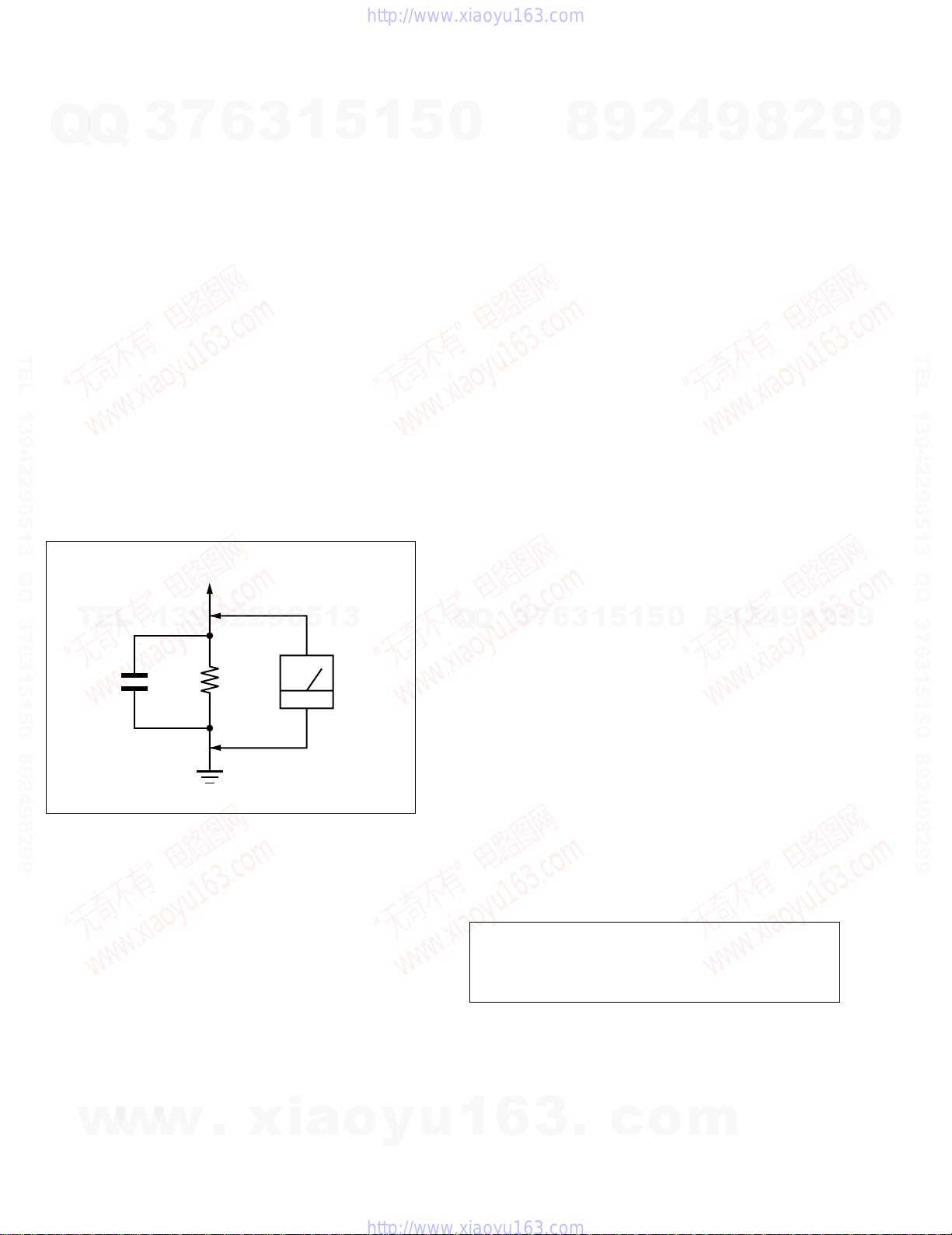
3. Measuring the v oltage drop across a resistor by means of a V OM
or battery-operated AC voltmeter. The “limit” indication is
0.75V , so analog meters must ha ve an accurate low-voltage scale.
The Simpson 250 and Sanwa SH-63Trd are examples of a
passive VOM that is suita ble. Nearly all battery operated digital
multimeters that have a 2V AC range are suitable. (See Fig. A)
8
9
2
4
9
8
2
9
9
TEL 13942296513 QQ 376315150 892498299
TEL
0.15 µF
Fig. A. Using an AC voltmeter to check AC leakage.
WHEN SERVICING, DO NO T APPRO A CH THE LASER
EXIT WITH THE EYE TOO CLOSELY. IN CASE IT IS
NECESSARY TO CONFIRM LASER BEAM EMISSION,
BE SURE TO OBSERVE FROM A DISTANCE OF
MORE THAN 25 cm FROM THE SURFACE OF THE
OBJECTIVE LENS ON THE OPTICAL PICK-UP BLOCK.
SAFETY-RELATED COMPONENT WARNING!!
COMPONENTS IDENTIFIED BY MARK 0 OR DOTTED
LINE WITH MARK 0 ON THE SCHEMATIC DIAGRAMS
AND IN THE PARTS LIST ARE CRITICAL TO SAFE
OPERATION. REPLACE THESE COMPONENTS WITH
SONY PARTS WHOSE PART NUMBERS APPEAR AS
w
SHOWN IN THIS MANUAL OR IN SUPPLEMENTS
PUBLISHED BY SONY.
13942296513
1.5 k
Ω
Earth Ground
WARNING!!
w
w
.
xia
AC
voltmeter
(0.75 V)
o
y
u
9
4
2
9
8
0
5
1
5
1
3
6
7
3
Q
Q
CAUTION:
The use of optical instrument with this product will increase eye
hazard.
CAUTION
Use of controls or adjustments or performance of procedures
other than those specified herein may result in hazardous
radiation exposure.
1
6
3
.
c
o
m
8
2
9
9
— 2 —

TABLE OF CONTENTS
Precautions
Q
TEL 13942296513 QQ 376315150 892498299
1 Safety Precautions ··································································4
Q
2 Servicing Precautions ···························································· 6
3 ESD Precautions·····································································7
4 Handling the Optical Pick-up ·················································8
5 Pick-up Disassembly and Reassembly ·································· 9
1. General
7
3
Getting Started···································································· 1-1
Basic Operations································································· 1-6
Advanced Hookups ·························································· 1-12
DVD Settings and Adjustments ········································ 1-13
DVD Additional Operations ············································ 1-16
VCR Additional Operations ············································· 1-22
Additional Information····················································· 1-24
6
3
1
5
1
5
0
2-4-25Belt Pulley Removal························································ 2-19
2-4-26Motor Capstan Ass’y Removal ······································· 2-19
2-4-27Post #8 Guide Ass’y Removal········································· 2-20
2-4-28Level Head Cleaner Ass’y Removal (Optional)·············· 2-20
2-4-29How to Eject the Cassette Tape ······································· 2-20
2-5 The Table Of Cleaning, Lubrication and
2-6 DVD Deck
2-6-1 Tray Disc Removal·························································· 2-22
2-6-2 Ass’y P/U Deck Removal ··············································· 2-23
2-6-3 Housing Ass’y Removal ·················································· 2-24
2-6-4 Sub Chassis Removal ······················································ 2-25
2-6-5 Ass’y Brkt Deck Removal··············································· 2-26
3. Block Diagram............................................................. 3-1
4
2
9
8
Replacement Time About Principal Parts ······················· 2-21
9
8
2
9
9
TEL 13942296513 QQ 376315150 892498299
2. Disassembly and Reassembly
2-1 Cabinet and PCB
2-1-1 Cabinet T op Remov al························································ 2-1
2-1-2 Bottom Cover Removal····················································· 2-1
2-1-3 Ass’y Front Panel Removal··············································· 2-1
2-1-4 Function PCB Removal····················································· 2-1
2-1-5 Chassis Removal ······························································· 2-2
2-1-6 VCR Main PCB Removal ················································· 2-2
2-2 Circuit Board Locations ···················································· 2-3
2-3 VCR Deck Parts Locations
2-3-1 T op Vie w ··········································································· 2-4
2-3-2 Bottom Vie w······································································ 2-6
2-4 VCR DECK
2-4-1 Holder FL Cassette Ass’y Removal ·································· 2-7
TEL
13942296513
2-4-2 Lever FL Door Removal ··················································· 2-7
2-4-3 Slider FL Drive, Gear FL Cam Removal ·························· 2-8
2-4-4 Lever FL Arm Ass’y Removal ·········································· 2-8
2-4-5 Gear W orm Wheel Removal·············································· 2-9
2-4-6 Cable Flat Removal··························································· 2-9
2-4-7 Motor Loading Ass’y Removal ······································· 2-10
2-4-8 Bracket Gear, Gear Joint 2, 1 Removal ··························· 2-10
2-4-9 Gear Loading Drive, Slider Cam,
Lever Load S, T Ass’y Removal ····································· 2-11
2-4-10Gear Loading Drive, Slider Cam,
Lever Load S, T Ass’y Assembly ···································· 2-11
2-4-11Lever Pinch Drive, Lever Tension Driv e Removal·········· 2-12
2-4-12Lever Tension Ass’y, Band Brake Ass’y Removal·········· 2-12
2-4-13Lever Brake S, T Ass’y Removal ···································· 2-13
2-4-14Gear Idle Ass’y Removal ················································ 2-13
2-4-15Disk S, T Reel Removal·················································· 2-14
2-4-16Holder Clutch Ass’y Removal········································· 2-14
2-4-17Lever Up Down Ass’y, Gear Center Ass’y Removal ······ 2-15
2-4-18Guide Cassette Door Removal ········································ 2-15
2-4-19Lever Unit Pinch Ass’y, Plate Joint,
Spring Pinch Drive Removal··········································· 2-16
2-4-20Lever #9 Guide Ass’y Removal ······································ 2-16
2-4-21FE Head Removal ··························································· 2-17
2-4-22ACE Head Removal ························································ 2-17
2-4-23Slider S, T Ass’y Removal ·············································· 2-18
2-4-24Plate Ground Deck, Cylinder Ass’y Removal················· 2-18
Q
Q
4. PCB Diagrams
4-1 VCR Main ·········································································· 4-3
4-2 DVD Main ·········································································· 4-7
4-3 Function-Timer··································································· 4-9
4-4 Dial-Timer ········································································ 4-11
5. Schematic Diagrams
◆ Block Identification of Main PCB············································ 5-3
5-1 S.M.P.S. ·············································································· 5-5
5-2 Power Drive········································································ 5-7
5-3 Logic/Function-Timer ························································ 5-9
5-4 Audio/Video ····································································· 5-11
5-5 Hi-Fi/MTS ········································································ 5-13
5-6 Input-Output ····································································· 5-15
6
7
3
5-7 DVD Main-Micom/AV Decoder ······································ 5-17
5-8 DVD Servo ······································································· 5-19
5-9 DVD Audio/V ideo ···························································· 5-21
6. Alignment and Adjustments
6-1 VCR Adjustment ································································ 6-1
6-1-1 Reference············································································ 6-1
6-1-2 Head Switching Point Adjustment ····································· 6-3
6-2 DVD Adjustment ································································ 6-4
6-2-1 Location of Test Point ························································ 6-4
6-2-2 Ske w Adjustment································································ 6-5
6-3 VCR Mechanical Adjustment············································· 6-7
6-3-1 Tape Transport System and Adjustment Locations ············ 6-7
6-3-2 Tape Transport System Adjustment···································· 6-8
6-3-3 Reel Torque ······································································ 6-13
7. Troubleshooting···················································· 7-1
8. Repair Parts List
8-1 Exploded Vie ws·································································· 8-2
8-1-1 Cabinet Assembly······························································· 8-2
8-1-2 VCR Mechanical Parts (Top Side) ····································· 8-3
8-1-3 VCR Mechanical Parts (Bottom Side) ······························· 8-4
8-1-4 DVD Mechanical Parts······················································· 8-5
8-2 Electrical Parts List ···························································· 8-6
3
1
5
1
5
0
8
9
2
4
9
8
2
9
9
w
w
w
.
xia
o
y
u
1
6
— 3 —
3
.
c
o
m
PRECAUTIONS
7
Q
Q
1 SAFETY PRECAUTIONS
1) Before returning an instr ument to the customer, always make a
safety check of the entire instrument, including, but not limited
to, the following items:
(1) Be sure that no built-in protective devices are defective or have
been defeated during servicing.
(1)Protective shields are provided to protect both the technician
and the customer. Correctly replace all missing protecti ve shields,
including any removed for servicing convenience.
TEL 13942296513 QQ 376315150 892498299
(2)When reinstalling the chassis and/or other assembly in the
cabinet, be sure to put back in place all protective devices,
including, but not limited to, nonmetallic control knobs, insulating
fish papers, adjustment and compartment covers/shields, and
isolation resistor/capacitor networks. Do not operate this
instrument or permit it to be operated without all protective de vices
correctly installed and functioning.
(2) Be sure that there are no cabinet openings through which adults
or children might be able to insert their fingers and contact a
hazardous voltage. Such openings include, but are not limited to,
excessively wide cabinet v entilation slots, and an improperly fitted
and/or incorrectly secured cabinet back cover.
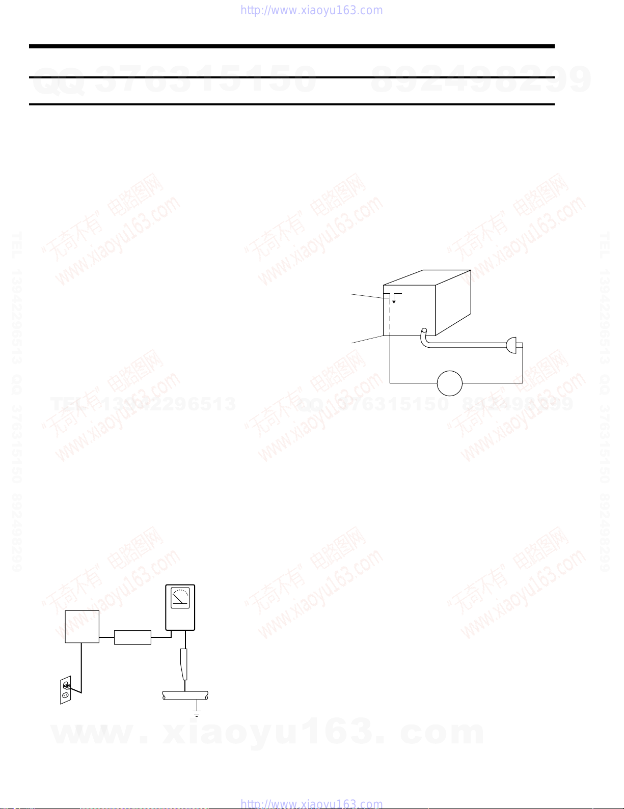
(3) Leakage Current Hot Check-With the instrument completely
reassembled, plug the A C line cord directly into a 120V AC outlet.
(Do not use an isolation transformer during this test.) Use a leakage
TEL
current tester or a metering system that complies with American
National Standards institute (ANSI) C101.1 Leakage Current for
Appliances and Underwriters Laboratories (UL) 1270 (40.7). W ith
the instrument’s A C switch first in the ON position and then in the
OFF position, measure from a known earth ground (metal water
pipe, conduit, etc.) to all exposed metal parts of the instrument
(antennas, handle brackets, metal cabinets, screwheads, metallic
overlays, control shafts, etc.), especially any exposed metal parts
that offer an electrical return path to the chassis.
Any current measured must not exceed 0.5mA. Reverse the
instrument power cord plug in the outlet and repeat the test. See
Fig. 1.
Any measurements not within the limits specified herein indicate
a potential shock hazard that must be eliminated before returning
the instrument to the customer.
w
3
13942296513
DEVICE
UNDER
TEST
EXPOSED METER
2-WIRE CORD
ALSO TEST WITH
PLUG REVERSED
(USING AC ADAPTER
PLUG AS REQUIRED)
w
w
6
TEST ALL
SURFACES
.
xia
Fig. 1 AC Leakage Test
3
LEAKAGE
CURRENT
TESTER
1
5
(READING SHOULD
NOT BE ABOVE
0.5mA)
EARTH
GROUND
o
1
y
5
u
0
(4) Insulation Resistance Test Cold Check-(1) Unplug the power
supply cord and connect a jumper wire between the two prongs of
the plug. (2) Turn on the power switch of the instrument. (3)
Measure the resistance with an ohmmeter between the jumpered
AC plug and all exposed metallic cabinet parts on the instrument,
such as screwheads, antenna, control shafts, handle brackets, etc.
When an exposed metallic part has a return path to the chassis, the
reading should be between 1 and 5.2 megohm. When there is no
return path to the chassis, the reading must be infinite. If the reading
is not within the limits specified, there is the possibility of a shock
hazard, and the instrument must be repared and rechecked before
it is returned to the customer. See Fig. 2.
Antenna
Terminal
Exposed
Metal Part
7
3
Q
Q
2) Read and comply with all caution and safety related notes on or
inside the cabinet, or on the chassis.
3) Design Alteration Warning-Do not alter or add to the mechanical
or electrical design of this instrument. Design alterations and
additions, including but not limited to, circuit modifications and
the addition of items such as auxiliary audio output connections,
might alter the safety characteristics of this instrument and create
a hazard to the user. An y design alterations or additions will make
you, the servicer, responsible for personal injury or property
damage resulting therefrom.
4) Observe original lead dress. Take e xtra care to assure correct lead
dress in the following areas:
(1) near sharp edges, (2) near thermally hot parts (be sure that
leads and components do not touch thermally hot parts), (3) the
AC supply, (4) high voltage, and (5) antenna wiring. Always inspect
in all areas for pinched, out-of-place, or frayed wiring, Do not
change spacing between a component and the printed-circuit board.
Check the AC power cord for damage.
5) Components, parts, and/or wiring that appear to have overheated
or that are otherwise damaged should be replaced with components,
parts and/ or wiring that meet original specifications.
Additionally, determine the cause of overheating and/or damage
and, if necessary, take corrective action to remove any potential
safety hazard.
1
6
3
4
2
9
8
ohm
0
5
1
5
1
3
6
Fig. 2 Insulation Resistance Test
.
c
o
m
9
ohmmeter
9
8
8
2
4
2
9
8
9
2
9
9
TEL 13942296513 QQ 376315150 892498299
9
— 4 —

7
Q
Q
TEL 13942296513 QQ 376315150 892498299
3
6) Product Safety Notice-Some electrical and mechanical parts have
special safety-related characteristics which are often not evident
from visual inspection, nor can the protection they give necessarily
be obtained by replacing them with components rated for higher
voltage, wattage, etc. Parts that have special safety char acteristics
are identified by shading, an ( ) or a ( ) on schematics and
parts lists. Use of a substitute replacement that does not have the
same safety characteristics as the recommended replacement part
might create shock, fire and/or other hazards. Product safety is
under review continuously and new instructions are issued
whenever appropriate.
6
3
1
5
1
5
0
8
9
2
4
9
8
2
9
9
TEL 13942296513 QQ 376315150 892498299
TEL
13942296513
Q
Q
3
7
6
3
1
5
1
5
0
8
9
2
4
9
8
2
9
9
w
w
w
.
xia
o
y
u
1
6
— 5 —
3
.
c
o
m

2 SERVICING PRECAUTIONS
7
Q
Q
CAUTION: Before servicing units covered by this service manual
and its supplements, read and follow the Safety Precautions section of
this manual.
Note: If unforseen circument create conflict between the following
servicing precautions and any of the safety precautions, always follow
the safety precautions. Remember: Safety First.
2-1 General Servicing Precautions
(1) a. Always unplug the instrument’s AC power cord from the AC
power source before (1) re-moving or reinstalling any
TEL 13942296513 QQ 376315150 892498299
component, circuit board, module or any other instrument
assembly, (2) disconnecting any instrument electrical plug or
other electrical connection, (3) connecting a test substitute in
parallel with an electrolytic capacitor in the instrument.
b. Do not defeat any plug/socket B+ voltage interlocks with which
instruments covered by this service manual might be equipped.
c. Do not apply AC power to this instrument and/or any of its
electrical assemblies unless all solid-state device heat sinks are
correctly installed.
d. Always connect a test instrument’s ground lead to the instrument
chassis ground before connecting the test instrument positive
lead. Always remove the test instrument ground lead last.
Note: Refer to the Safety Precautions section ground lead last.
3
6
3
1
5
1
5
0
8
9
2
4
9
8
2
9
9
TEL 13942296513 QQ 376315150 892498299
(2) The service precautions are indicated or printed on the cabinet,
chassis or components. When servicing, follow the printed or
TEL
indicated service precautions and service materials.
(3) The components used in the unit have a specified flame resistance
and dielectric strength.
When replacing components, use components which have the same
ratings. Components identified by shading, by (
the circuit diagram are important for safety or for the characteristics
of the unit. Always replace them with the exact replacement
components.
(4) An insulation tube or tape is sometimes used and some components
are raised above the printed wiring board for safety. The internal
wiring is sometimes clamped to prevent contact with heating
components. Install such elements as they were.
(5) After servicing, always check that the removed screws,
components, and wiring have been installed correctly and that the
portion around the serviced part has not been damaged and so on.
Further, check the insulation between the blades of the attachment
plug and accessible conductive parts.
2-2 Insulation Checking Procedure
Disconnect the attachment plug from the A C outlet and turn the power
ON. Connect the insulation resistance meter (500V) to the blades of
the attachment plug. The insulation resistance between each blade of
the attachment plug and accessible conductive parts (see note) should
be more than 1 Megohm.
13942296513
) or by ( ) in
Q
Q
3
7
6
3
1
5
1
5
0
8
9
2
4
9
8
2
9
9
Note: Accessible conductive parts include metal panels, input
w
w
terminals, earphone jacks, etc.
w
.
xia
o
y
u
1
— 6 —
6
3
.
c
o
m

3 ESD PRECAUSIONS
7
Q
Q
TEL 13942296513 QQ 376315150 892498299
TEL
3
Electrostatically Sensitive Devices (ESD)
Some semiconductor (solid state) devices can be damaged easily by
static electricity.
Such components commonly are called Electrostatically Sensitive
Devices (ESD). Examples of typical ESD devices are integrated circuits
and some field-effect transistors and semiconductor chip components.
The following techniques should be used to help reduce the incidence
of component damage caused by static electricity.
(1) Immediately before handling any semiconductor component or
semiconductor-equipped assembly, drain off any electrostatic
charge on your body by touching a known earth ground.
Alternatively, obtain and wear a commercially available
discharging wrist strap device, which should be removed for
potential shock reasons prior to applying power to the unit under
test.
(2) After removing an electrical assembly equipped with ESD devices,
place the assembly on a conductive surface such as aluminum foil,
to prevent electrostatic charge b uildup or exposure of the assembly .
(3) Use only a grounded-tip soldering iron to solder or unsolder ESD
devices.
(4) Use only an anti-static solder removal devices. Some solder
removal devices not classified as “anti-static” can generate
electrical charges sufficient to damage ESD devices.
13942296513
(5) Do not use freon-propelled chemicals. These can generate electrical
charges sufficient to damage ESD devices.
6
3
1
5
1
5
0
Q
Q
3
7
6
8
3
9
1
5
1
2
5
4
0
9
8
9
8
2
4
2
9
8
9
2
9
9
TEL 13942296513 QQ 376315150 892498299
9
(6) Do not remove a replacement ESD device from its protective
package until immediately before your are ready to install it. (Most
replacement ESD devices are packaged with leads electrically
shorted together by conductive foam, aluminum foil or comparable
conductive materials).
(7) Immediately before removing the protective materials from the
leads of a replacement ESD device, touch the protective material
to the chassis or circuit assembly into which the device will be
installed.
CAUTION: Be sure no power is applied to the chassis or circuit, and
observe all other safety precautions.
(8) Minimize bodily motions when handling unpackaged replacement
ESD devices. (Otherwise harmless motion such as the brushing
together of your clothes fabric or the lifting of your foot from a
carpeted floor can generate static electricity sufficient to damage
an ESD device).
w
w
w
.
xia
o
y
u
1
6
3
.
c
o
m
— 7 —
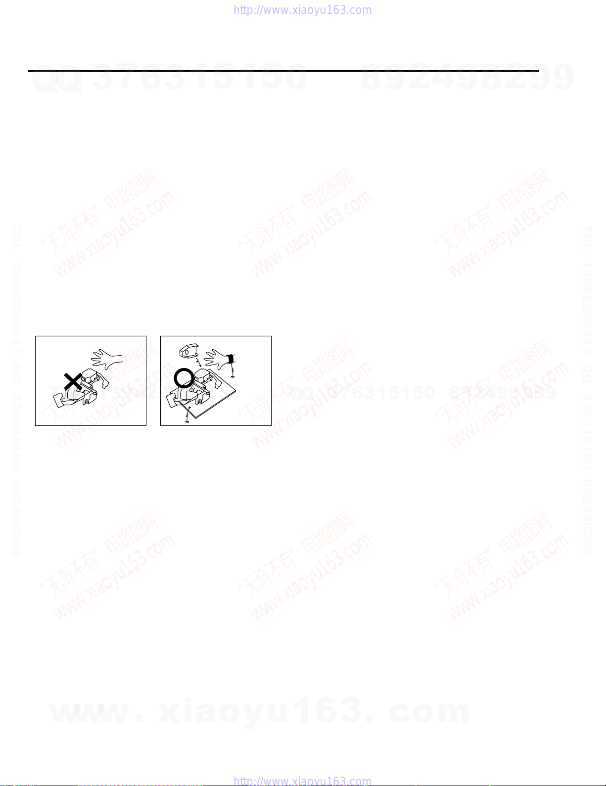
4 HANDLING THE OPTICAL PICK-UP
7
Q
Q
The laser diode in the optical pick up may suffer electrostatic
breakdown because of potential static electricity from clothing and
your body.
The following method is recommended.
(1) Place a conductive sheet on the work bench (The black sheet used
for wrapping repair parts.)
(2) Place the set on the conductive sheet so that the chassis is grounded
to the sheet.
(3) Place your hands on the conductive sheet(This gives them the same
TEL 13942296513 QQ 376315150 892498299
ground as the sheet.)
(4) Remove the optical pick up block
(5) Perform work on top of the conductive sheet. Be careful not to let
your clothes or any other static sources to touch the unit.
◆ Be sure to put on a wrist strap grounded to the sheet.
◆ Be sure to lay a conductive sheet made of copper etc. Which is
grounded to the table.
3
6
3
1
5
WRIST-STRAP
FOR GROUNDING
1
1M
5
0
8
9
2
4
9
8
2
9
9
TEL 13942296513 QQ 376315150 892498299
TEL
(6) Short the short terminal on the PCB, which is inside the Pick-Up
ASS’Y , before replacing the Pick-Up. (The short terminal is shorted
when the Pick-Up Ass’y is being lifted or moved.)
(7) After replacing the Pick-up, open the short terminal on the PCB.
THE UNIT
13942296513
1M
Fig.3
CONDUCTIVE SHEET
Q
Q
3
7
6
3
1
5
1
5
0
8
9
2
4
9
8
2
9
9
w
w
w
.
xia
o
y
u
1
6
— 8 —
3
.
c
o
m
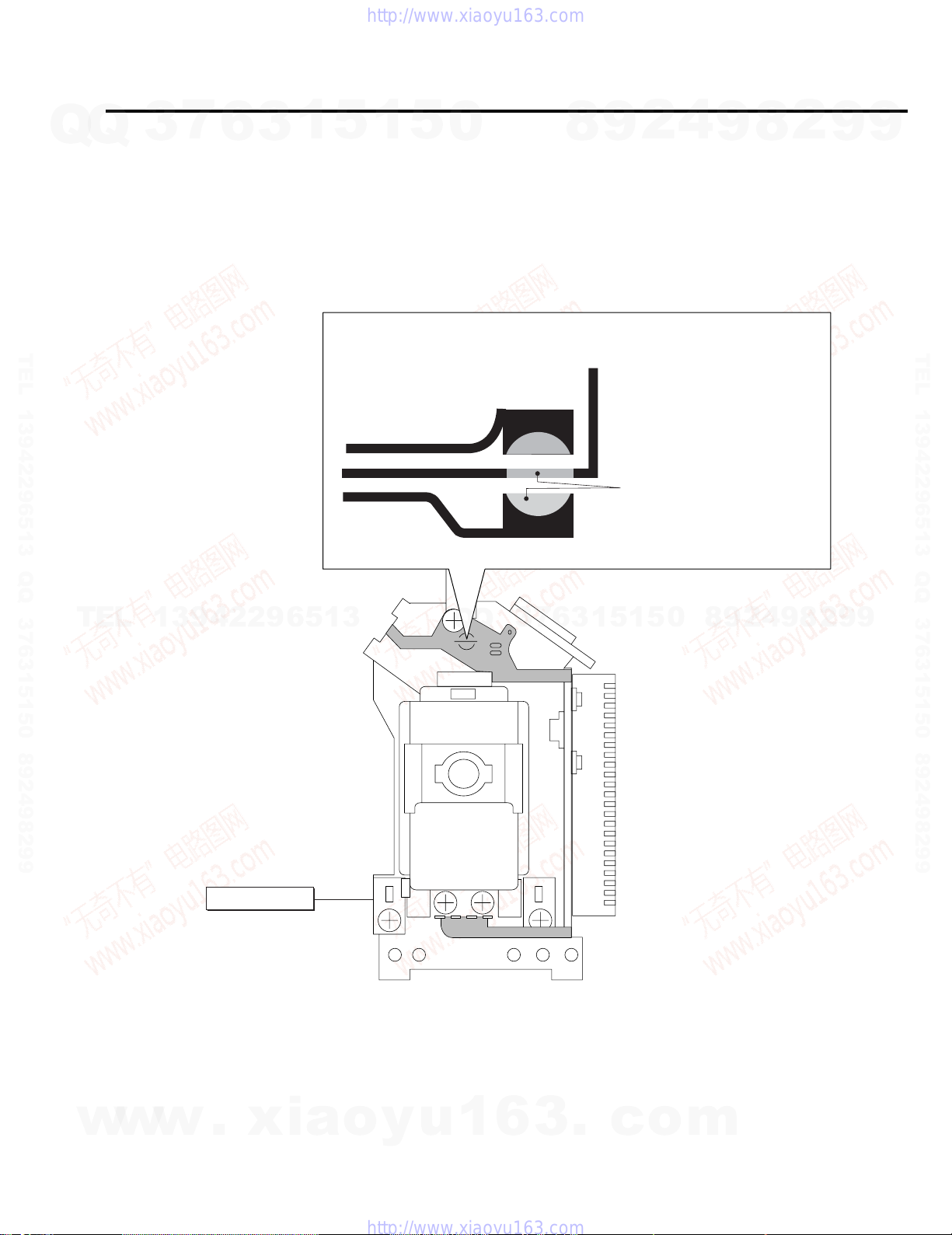
5 PICK-UP DISASSEMBLY AND REASSEMBLY
7
Q
Q
TEL 13942296513 QQ 376315150 892498299
3
5-1 Disassembly
1) Remove the power cord.
2) Disassemble the Deck-Assy.
3) Make solder land 2 points short on Pick-up.
(See Fig. 4)
4) Disassembly the Pick-up.
Note: If the assembly and disassembly are not done in correct sequence, the Pick-up may be damaged.
6
3
1
5
1
5
0
5-2 Assembly
1) Replace the Pick-up.
2) Remove the soldering 2 points on Pick-up.
3) Reassemble the Deck-Assy.
8
4
2
9
SOLDER LAND 2 POINTS SHORT
9
8
2
9
9
TEL 13942296513 QQ 376315150 892498299
TEL
13942296513
PICK-UP ASS'Y
Q
Q
Fig. 4
3
7
6
3
1
5
1
5
0
8
9
2
4
9
8
2
9
9
w
w
w
.
xia
o
y
u
1
6
— 9 —
3
.
c
o
m

MEMO
Q
Q
3
7
6
3
1
5
1
5
0
8
9
2
4
9
8
2
9
9
TEL 13942296513 QQ 376315150 892498299
TEL
13942296513
Q
Q
3
7
6
3
1
5
1
5
0
8
9
2
4
9
8
2
9
TEL 13942296513 QQ 376315150 892498299
9
w
w
w
.
xia
o
y
u
1
6
— 10 —
3
.
c
o
m
SLV-D500P
1. GENERAL
Q
Getting Started
Q
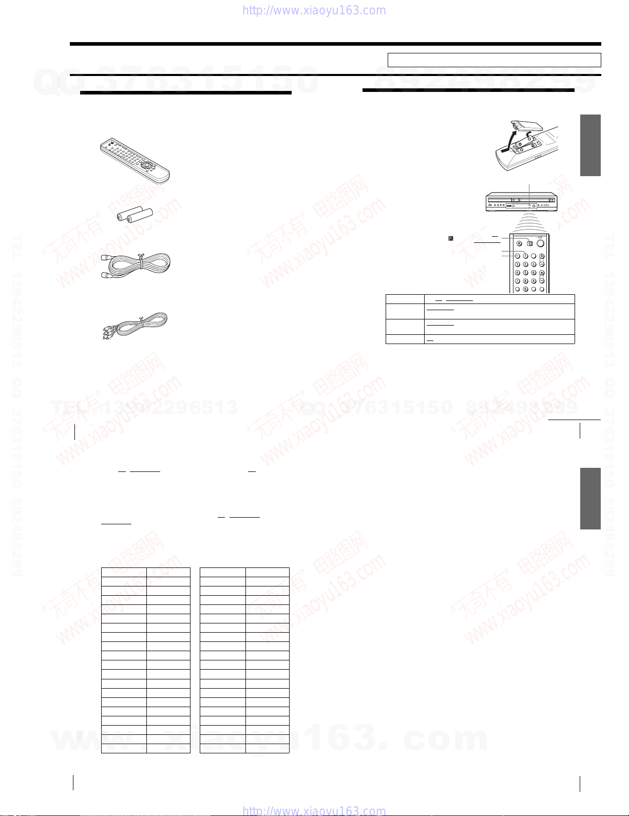
Step 1 : Unpacking
Check that you have received the following items with the DVD-VCR:
•Remote commander
•Size AA (R6) batteries
TEL 13942296513 QQ 376315150 892498299
•75-ohm coaxial cable with F-type connectors
•Audio/video cord
(pinplug ×3 y pinplug ×3)
TEL
8
Unpacking
w
w
3
7
6
3
1
5
1
13942296513
Controlling other TVs with the remote commander
The remote commander is preprogramed to cont rol non-Sony TVs. If your TV is
listed in the following table, set the appropriate manufacturer’s code number.
Set TV / DVD·VIDEO at the top of the remote commander to TV.
1
Hold down ?/1, and enter your TV’s code number using the number buttons.
2
Then release ?/1.
Now you can use the ?/1, VOL +/–, CH +/–, MUTING*, TV/VIDEO and ENTER*
buttons to control your TV. You can also use the buttons marked with a dot (•) to
control a Sony TV. To co ntrol the DVD-VCR, reset TV
.
DVD·VIDEO
*for Sony TV only
Code numbers of controllable TVs
If more than one code number is listed, try entering them one at a time until you find
the one that works with your TV.
TV brand Code number
Sony 01
Akai 04
AOC 04
Centurion 12
Coronado 03
Curtis-Mathes 12
Daytron 12
Emerson 03, 04, 14
Fisher 11
General Electric 06, 10
Gold Star 03, 04, 17
Hitachi 02, 03
J.C.Penney 04, 12
JVC 09
KMC 03
Magnavox 0 3, 08, 12
Marantz 04, 13
MGA/Mitsubishi 04, 12, 13, 17
NEC 04, 12
w
.
xia
/ DVD·VIDEO to
TV brand C ode number
Panasonic06, 19
Philco 03, 04
Philips 08
Pioneer 16
Portland 03
Quasar 06, 18
Radio Shack 05, 14
RCA 04, 10
Sampo 12
Sanyo 11
Scott 12
Sears 07, 10, 11
Sharp 03, 05, 18
Sylvania 08, 12
Tek nik a03, 08, 14
Tos hi ba 07
Wards 03, 04, 12
Yor x 12
Zenith 15
o
y
5
u
0
Q
Q
1
3
6
7
3
This section is extracted from instruction manual. (3-083-947-11)
4
2
9
8
Step 2 : Setting up the remote commander
Inserting the batteries
Insert two size AA (R6) batteries
by matching the + and – on the
batteries to the diagram inside the
battery compartment.
Insert the negative (–) end first,
then push in and down until the
positive (+) end clicks into
position.
Using the remote
commander
You can use this remote
commander to operate this DVDVCR and a Sony TV. Buttons on
the remote commander marked
with an orange dot (•) can be used
to operate your Sony TV.
If the TV does not have the
symbol near the remote sensor, this
remote commander will not
operate the TV.
To operate Set TV / DVD·VIDEO to
the DVD player DVD·VIDEO
the VCR DVD·VIDEO
your TV TV
Notes
•With normal use, the batteries should last about three to six months.
•If you do not use the remote commander for an extended period of time, rem ove the batteries
to avoid possible damage from battery leakag e.
•Do not use a new battery with an old one.
•Do not use different types of batteries.
•Do not leave the remote commander in an extremely hot or humid place.
•Do not drop any foreign object into the remote casing, particularly when replacing the batteries.
•Do not expose the remote sensor to direct light from the sun or lighting apparatus. Doing so
may cause a malfunction.
5
1
3
6
Notes
•If you enter a new code number, the code number previously entered will be eras ed.
•If the TV uses a different remote control system from the one pro gramed to work with the
DVD-VCR, you cannot control your TV with the remote com mander.
•When you replace the batteries of the remote commander, the code numb er may change. Set
the appropriate code number every time you replac e the batteries.
.
c
the DVD-VCR
at the DVD-VCR
and point at the remote sensor at your TV
0
5
1
o
9
TV /
DVD· VIDEO
SELECT VIDEO
SELECT DVD
, then press SELECT DVD and point at the remote sensor at
, then press SELECT VIDEO and point at the remote sensor
2
9
8
m
2
8
9
2
continued
9
8
Remote sensor
9
4
Setting up the remote commander
9
Getting Started
TEL 13942296513 QQ 376315150 892498299
9
9
Getting Started
10
Setting up the remote commander
1-1
Setting up the remote commander
11
s
Step 3 : Basic hookups
Q
Q
Before you get started
•Be sure to disconnect the AC power cord of each component before connecting.
•Turn off the power to all equipment.
•Do not connect the AC power cords until all of the connections are completed. If
you connect the AC power cord before the connections are completed, you may not
be able to use the Plug and Play function.
•Be sure you make connections firmly. Loose connections may cause picture
distortion.
• If your TV does not match any of the examples provided, see your nearest Sony
dealer or qualified technician.
Selecting the best hookup option
There are many ways in which your DVD-VCR can be hooked up. To hook up your
DVD-VCR so that it works best for you, first scan through the table below. Then use
the accompanying diagrams and procedures on t he following pages to set up your
DVD-VCR.
If your TV has audio/video inputs, r efer to page 13 for audio/video ( A/V) hookup.
Then follow one of the hookups below. If your TV does not have A/V inputs, go
TEL 13942296513 QQ 376315150 892498299
12
directly to one of the hookups below.
If you have UseRefer to
Antenna only, no cable TV Hookup 1
No cable box or cable box with only a
few scrambled channels
Cable box with many scrambled
channels
After you have completed the connections, follow the instructions for setup.
After you have completed the setup, you are re ady to use your DVD-VCR.
Procedures differ depending on the hooku p you used.
Caution
Connections between the DVD-VCR’s VHF/UH F connector and the antenna terminal s of the
TV receiver should be made only as shown in the following instructions. Failure to do so may
result in operation that violate s the regulations of the Fed eral Communications Commi ssion
regarding the use and operation of R F devices. Never connect the output of the DVD-VCR to an
antenna or make simultaneous (parallel) antenna an d DVD-VCR connections at the antenna
terminals of your receiver.
Note to CATV system installer (in USA)
This reminder is provided to call the CATV system installer’s attention to Article 820- 40 of the
NEC that provides guidelines for proper grounding and, in partic ular, specifies that the cable
ground shall be connected to the grounding system of the building, as close to the point of cable
entry as practical.
Basic hookups
TEL
3
7
6
(Plug and Play)
Hookup 2
(Plug and Play)
Hookup 3 Page 18
3
1
Pages 14 and 15
Pages 16 and 17
13942296513
5
1
5
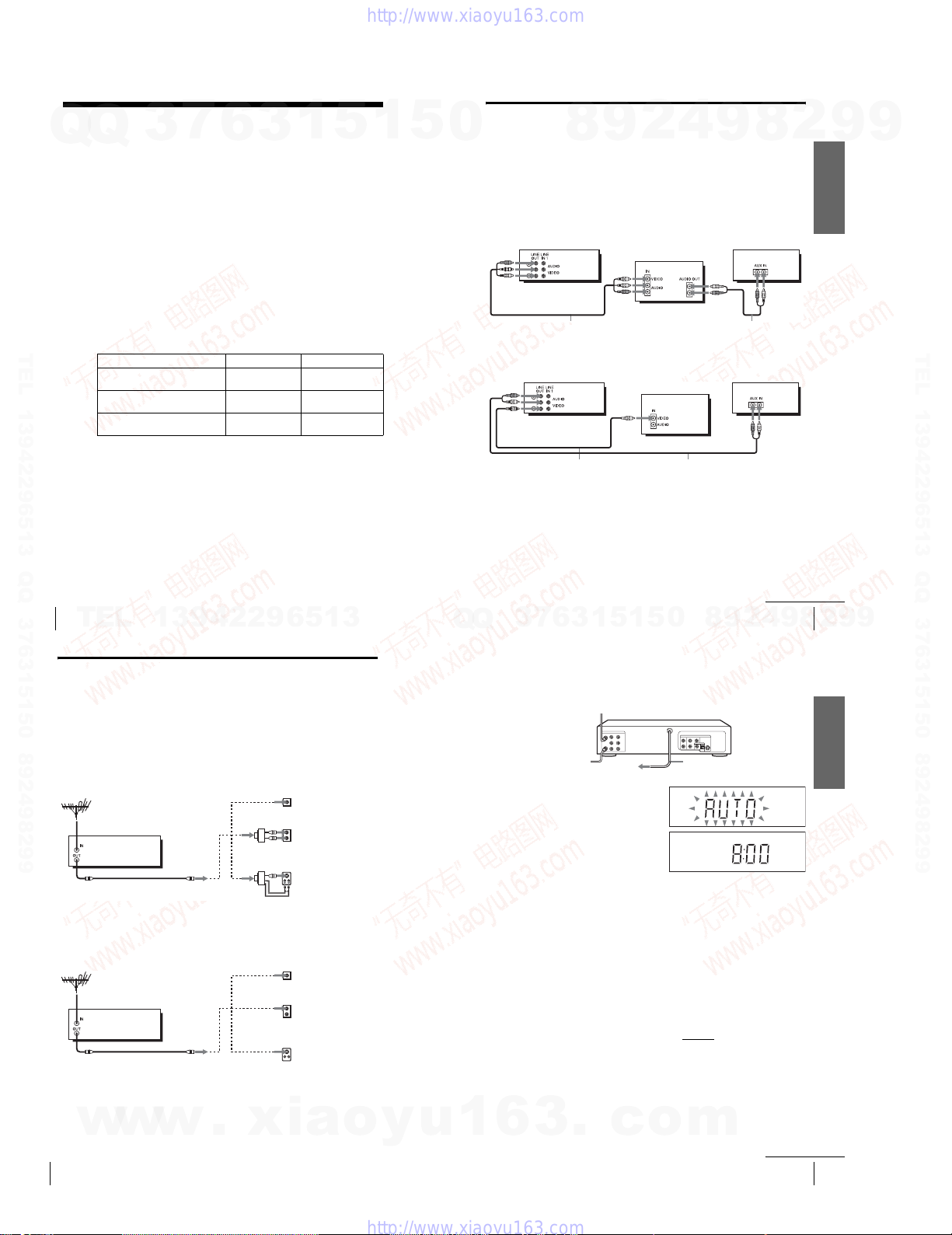
Audio/video (A/V) hookup
If your TV has audio/video (A/V) input jacks, you will get better picture and sound if
0
Q
Q
you hook up your DVD-VCR using these connections. If your T V does not have A/V
inputs, see the following pages for antenna or cable hookups. Note that “Advanced
Hookups” (page 55) explains additional hookup methods that will optimize the
picture and sound for a true “hometheater” experience.
If you are not planning to use your DVD-VCR to record pro grams, you only need to
make the connections shown on this page. If you want to record regular or cable TV
programs, complete these connections first, and then go to the following pages for
antenna or cable hookups.
A Use this hookup if your TV has stereo jacks
Audio/video cord (supplied)
B Use this hookup if your TV does not have stereo jacks
Notes
•To play a tape/disc in stereo, you must use the A/V connection.
•If you do not have a stereo receiver, connect the white LINE OUT/AUDIO L jack to the
3
Video cord (not supplied)TVAudio co rd (not supplied)
AUDIO IN jack on your TV.
7
DVD- VCR
DVD- VCR
6
8
3
9
1
5
1
2
5
TV
0
4
9
Stereo receiver
Audio c ord (not supplied)
Stereo receiver
2
9
8
8
continued
Basic hookups
9
4
2
8
Getting Started
13
2
9
9
9
TEL 13942296513 QQ 376315150 892498299
9
Hookup 1 (Plug and Play)
Antenna hookup
Make the following connections if you are using an antenna (if you do not have cable
TV).
A Use this hookup if you are using:
• VHF/UHF antenna (you get channels 2–13 and channels 14 and high er)
• UHF-only antenna (you get channels 14 and higher)
•Separate VHF and UHF antennas
DVD- VCR
B Use this hookup if you are using a VHF-only antenna (you get
channels 2–13 only)
DVD- VCR
If you cannot connect your antenna cable to the DVD-VCR directly
If your antenna cable is a flat cable (300-ohm twin lea d cable), attach an external
antenna connector (not supplied) so you can co nnect the cable to the RF IN
connector. If you have separate cables for VHF and UHF an tennas, you should use a
w
w
U/V band mixer (not supplied) (page 102) .
14
Basic hookups
w
or
or
or
or
.
xia
Rear of TV
VHF/UHF
VHF
UHF
VHF
UHF
Rear of TV
VHF/UHF
VHF
UHF
VHF
UHF
Match the type of
A
connector on your
TV: A, B, or C.
B
C
Match the type of
A
connector on your
TV: A, B, or C.
For connector type
B
B and C, no UHF
connection is
required.
C
o
y
u
Hookup 1 : DVD-VCR setup
Plug the DVD-VCR into an AC outlet.
The DVD-VCR automatically presets the DVD-VCR’s clock and TV channels
when the DVD-VCR is plugged into the AC outlet.
The DVD-VCR starts presetting the
clock and channels.
When Auto preset is completed, the
current time appears in the display
window.
You have now completed DVD-VCR setup.
To c han ge the on-screen display language to French or S panish, see
“Step 4 : Selecting a language” on page 19.
The clock is set using a time signal provided by some TV channels. If the clock
is incorrect, or “--:--” appears in the display window, see “Using Manual Clock
Set” on page 22.
To add or disable channels manually, s ee “Presetting/disabling channels
manually” on page 26.
Notes
• If you connect the AC power cord before the antenna connections are completed, the channels
may be incorrectly set. If this happens, see “Step 6 : Presetting channels” on page 24.
•Do not press any buttons on the DVD-VCR or remote commander during Auto preset.
•Auto preset starts automatically only when you plug in the AC power cord for the first time
after you purchase the DVD-VCR.
•Auto preset can be performed by pressing x STOP on the unit
more with the DVD-VCR power turned off.
1
6
3
.
to AC outlet
c
o
AC power cord
continuously for 5 seconds or
m
continued
Basic hookups
Getting Started
15
1-2
Hookup 2 (Plug and Play)
You have no cable box, or a cable box with only a few
7
Q
Q
TEL 13942296513 QQ 376315150 892498299
3
scrambled channels
Recommended use
Use this hookup if you do not have a cable box. Also use this hookup if your cable
system scrambles only a few channels.
What you can do with this hookup
•Record any unscrambled channel by selecting the channel on the VCR
What you cannot do
•Record scrambled channels that require a cable box
Wall
Connect this cable
directly to your TV if
you do not have a
cable box.
6
DVD- VCR
Cable box
3
1
5
Rear of TV
VHF/UHF
or
or
1
VHF
UHF
VHF
UHF
5
Match the type
A
of connector
on your TV: A,
B, or C.
B
For connector
types B and C,
no UHF
connection is
required.
C
0
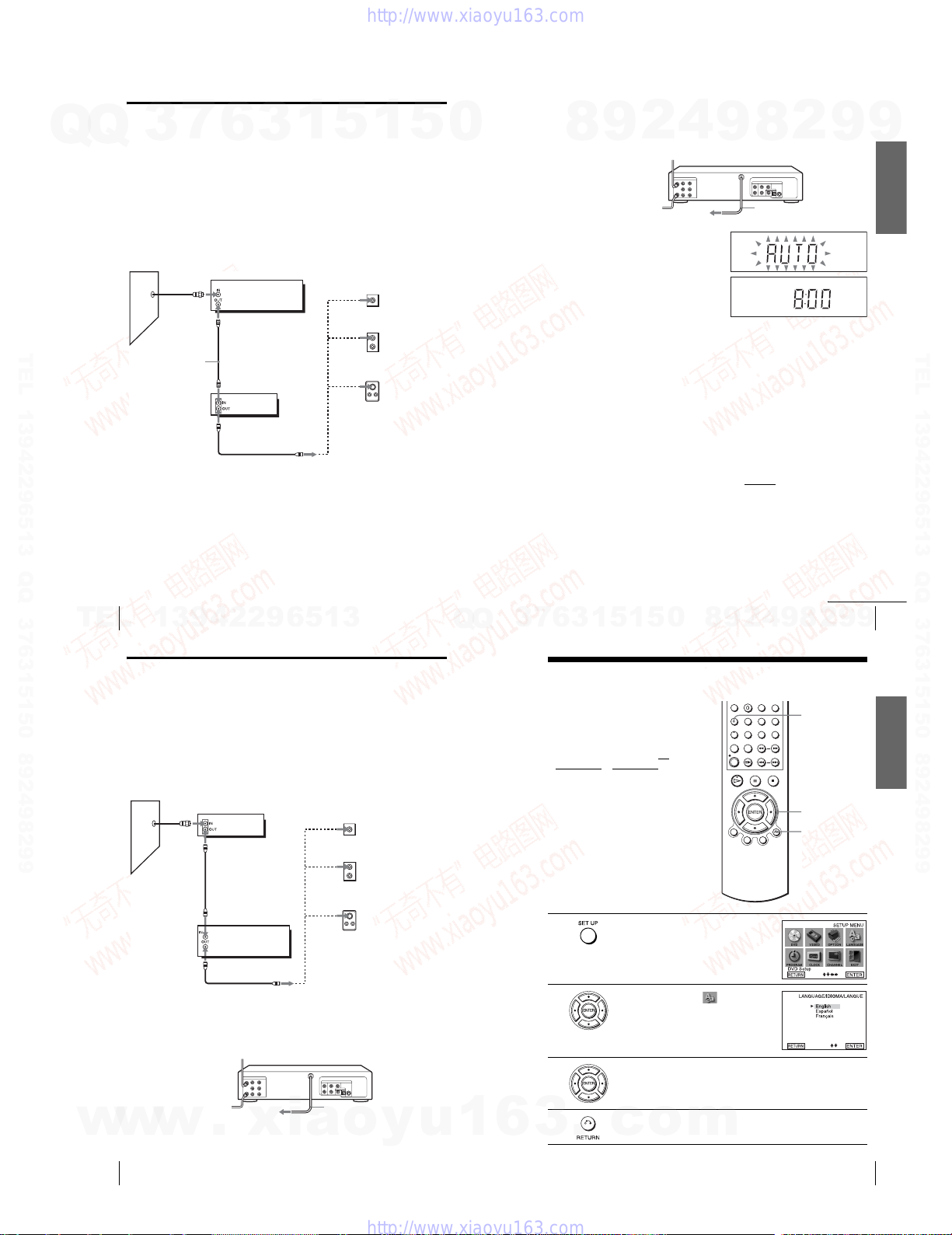
Hookup 2 : DVD-VCR setup
Plug the DVD-VCR into an AC outlet.
The DVD-VCR automatically presets the DVD-VCR’s clock and TV channels
9
8
when the DVD-VCR is plugged into the AC outlet.
The DVD-VCR starts presetting the
clock and channels.
When Auto preset is completed, the
current time appears in the display
window.
You have now completed DVD-VCR setup.
To c han ge the on-screen display language to French or S panish, see
“Step 4 : Selecting a language” on page 19.
The clock is set using a time signal provided by some TV channels. If the clock
is incorrect, or “--:--” appears in the display window, see “Using Manual Clock
Set” on page 22.
To add or disable channels manually, s ee “Presetting/disabling channels
manually” on page 26.
Notes
• If you connect the AC power cord before the antenna connections are completed, the channels
may be incorrectly set. If this happens, see “Step 6 : Presetting channels” on page 24.
•Do not press any buttons on the DVD-VCR or remote commander during Auto preset.
•Auto preset starts automatically only when you plug in the AC power cord for the first time
after you purchase the DVD-VCR.
•Auto preset can be performed by pressing x STOP on the unit
more with the DVD-VCR power turned off.
2
4
to AC outlet
9
8
AC pow er cord
continuously for 5 seconds or
2
9
9
Getting Started
TEL 13942296513 QQ 376315150 892498299
16
TEL
Basic hookups
13942296513
Hookup 3
Connecting a cable box with many scrambled channels
Recommended use
Use this hookup if your cable system scrambles all or most channels.
What you can do with this hookup
•Record any channel by selecting the channel on the cab le box
What you cannot do
•Record with the cable box turned off
•Record one channel while watching another cha nnel
Wall
After you have completed hookup…
After you have completed hookup, plug the DVD-VCR into an AC outlet and see
“Step 4 : Selecting a language” on page 19 .
Cable box
DVD-VC R
or
or
Rear of TV
VHF/UHF
VHF
UHF
VHF
UHF
A
Match the type of
connector on your
TV: A, B, or C.
B
For connector
types B and C, no
UHF connection
is required.
C
Q
Q
0
5
1
5
1
3
6
7
3
Step 4 : Selecting a language
You can change the on-sc reen display
language.
Before you start…
•Turn on the DVD-VCR and your TV.
•To control the DVD-VCR, set TV /
DVD·VIDEO
to DVD·VIDEO on the
remote (page 9).
•Set the “RF Output Channel” to “3CH” or
“4CH” in “OPTION SETUP” menu
(page 100). If your TV is conn ected to the
DVD-VCR using A/V connections, set the
TV to video input.
• If the DVD player is in play mode, you
cannot display the “SETUP MENU.” Stop
the DVD playback.
1
2
3
Press SET UP.
The “SETUP MENU” appears.
Press V/v/B/b to select (Language/
Idioma/Langue), then press ENTER.
The “LANGUAGE/IDIOMA/LANGUE”
menu appears.
Press V/v to select the desired language, English, Spanish or French, then
press ENTER.
8
9
2
4
9
Basic hookups
2
8
SET UP
V/v/B/b
ENTER
O RETURN
continued
9
9
17
Getting Started
w
w
18
w
Basic hookups
.
xia
to AC outlet
AC pow er cord
o
y
u
1
6
1-3
4
3
Press O RETURN to exit the menu.
.
c
o
m
Selecting a language
19

Step 5 : Setting the clock
Q
Q
Using the Auto Clock Set
feature
Some TV and cable channels transmit time
signals with their broadcasts. Your DVDVCR can pick up this time signal to
automatically set the clock.
The Auto Clock Set feature works only if a
channel in your area is broadcasting a time
signal. If broadcasters in your area are not
yet sending time signals, set the time
manually (page 22).
Before you start…
•Turn on the DVD-VCR and your TV.
When using a cable box, turn it on.
•To control the DVD-VCR, set TV
DVD·VIDEO to DVD·VIDEO on the
remote (page 9).
•Set the “RF Output Channel” to “3CH” or
TEL 13942296513 QQ 376315150 892498299
“4CH” in “OPTION SETUP” menu
(page 100). If your TV is conn ected to the
DVD-VCR using A/V connections, set the
TV to video input.
• If the DVD player is in play mode, you
cannot display the “SETUP MENU.” Stop
the DVD playback.
1
2
Press SET UP.
The “SETUP MENU” appears.
Press V/v/B/b to select (Clock Set/
Adjust), then press ENTER.
The “CLOCK SET/ADJUST” menu appears.
3
7
/
6
3
1
SET UP
V/v/B/b
ENTER
O RETURN
5
1
5
3
0
4
5
6
Press V/v to select “Auto”, then press
ENTER.
9
8
Press V/v to select the item you want. Then press B/b to ma ke the setting.
•For “Clock data CH”
Leave the setting to “Auto” to have the
DVD-VCR automatically search for a
channel that carries a time signal. Press
to select a channel that carries a time signal.
Use this option if you know of a channel that
carries a time signal. Most PBS member
stations broadcast a time signal. For the
fastest response, select your local PBS
station.
•For “Time zone”
Select the time zone of your area, or select
“Auto” to have the DVD-VCR automatically
set your time zone.
The options are:
Auto y Atl. (Atlantic) y East (Eastern)
y Cen. (Central) y Mtn. (Mountain) y
Pac. (Pacific) y Alas (Alaska ) y
Haw. (Hawaii) y Auto
•For “Daylight saving”
Select “Yes” or “No” (standard time), or
“Auto” to have the DVD-VCR automatically
set the daylight saving time.
Press O RETURN repeatedly to exit the menu.
To activate the Auto Clock Set function, turn off the DVD-VCR.
2
4
B/b
9
8
2
9
Getting Started
9
TEL 13942296513 QQ 376315150 892498299
20
Setting the clock
TEL
Notes
•The clock cannot be set automatically if you do not receive a channel th at carries a time
signal in your area. If so, set the clock manually (page 22).
• If there are only a few channels in your area that ca rry time signals, setting the clock
automatically may take up to about 20 minutes. If nothing happens even after you wait abou t
20 minutes, set the clock manually (page 22).
• If you made Hookup 3, make sure you leave the cable box on.
•To record TV programs using the timer, you must set the clock accurately.
•The clock display appears when VIDEO mode is selected with no tape inserted or when the
DVD-VCR is turned off.
Using Manual Clock Set
Before you start…
•Turn on the DVD-VCR and your TV.
•To control the DVD-VCR, set TV /
DVD·VIDEO
remote (page 9).
•Set the “RF Output Channel” to “3CH” or
“4CH” in “OPTION SETUP” menu
(page 100). If your TV is conn ected to the
DVD-VCR using A/V connections, set the
TV to video input.
• If the DVD player is in play mode, you
cannot display the “SETUP MENU.” Stop
the DVD playback.
1
13942296513
to DVD·VIDEO on the
Press SET UP.
The “SETUP MENU” appears.
SET UP
V/v/B/b
ENTER
O RETURN
Q
Q
8
0
5
1
5
1
3
6
7
3
3
4
5
6
7
Press V/v to select “Manual,” then press
ENTER.
Press V/v to set the hour.
Press b to select the minutes and press V/v to
set the minutes.
Set the month, day, and year in the same way as the minutes.
The day of the week is set automatically.
Press O RETURN to save the clock setting.
Notes
•To record TV programs using the timer, you must set the clock accurately.
•The clock display appears when VIDEO mode is selected with no tape inserted or when the
DVD-VCR is turned off.
9
continued
Setting the clock
4
2
9
8
21
2
Getting Started
9
9
2
22
Setting the clock
w
w
Press V/v/B/b to select (Clock Set/
Adjust), then press ENTER.
The “CLOCK SET/ADJUST” menu appears.
w
.
xia
o
y
u
1
6
1-4
3
.
c
o
m
Setting the clock
23
Step 6 : Presetting channels
Q
Q
This DVD-VCR is capable of receiving VHF
channels 2 to 13, UHF channels 14 to 69 and
unscrambled CATV channels 1 to 125. First,
we recommend that you preset the receivable
channels in your area using automatic
presetting methods. Then, if there are any
unwanted channels, disable them manually.
If you have already decided which channels
you wish to preset, set them directly using
manual presetting methods (page 26).
Presetting all receivable
channels automatically
Before you start…
•Turn on the DVD-VCR and your TV.
•To control the DVD-VCR, set TV
TEL 13942296513 QQ 376315150 892498299
•Set the “RF Output Channel” to “3CH” or
• If the DVD player is in play mode, you
1
2
7
3
When using a cable box, turn it on.
DVD·VIDEO
remote (page 9).
“4CH” in “OPTION SETUP” menu
(page 100). If your TV is conn ected to the
DVD-VCR using A/V connections, set the
TV to video input.
cannot display the “SETUP MENU.” Stop
the DVD playback.
6
3
to DVD·VIDEO on the
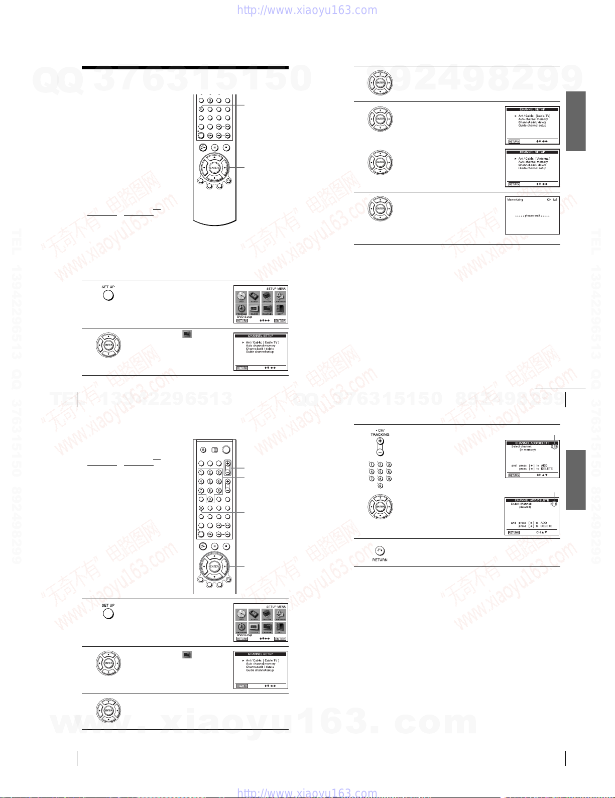
Press SET UP.
The “SETUP MENU” appears.
Press V/v/B/b to select (Channel
Setup), then press ENTER.
The “CHANNEL SETUP” menu appears.
/
1
5
1
SET UP
V/v/B/b
ENTER
5
0
3
4
5
8
Press V/v to select “Ant/Cable.”
4
2
9
•To preset cable TV channels:
Press B/b to select “Cable TV.”
•To preset VHF and UHF channels:
Press B/b to select “Antenna.”
Press V/v to select “Auto channel memory,”
then press ENTER.
All receivable channels are preset in numerical
sequence. When no more receivable channels
can be found, presetting stops and the picture
from the lowest numbered channel is displayed
on the TV screen.
9
8
2
9
9
Getting Started
TEL 13942296513 QQ 376315150 892498299
24
TEL
Presetting channels
13942296513
Presetting/disabling channels manually
Before you start…
•Turn on the DVD-VCR and your TV.
When using a cable box, turn it on.
•To control the DVD-VCR, set TV
DVD·VIDEO to DVD·VIDEO on the
remote (page 9).
•Set the “RF Output Channel” to “3CH” or
“4CH” in “OPTION SETUP” menu
(page 100). If your TV is conn ected to the
DVD-VCR using A/V connections, set the
TV to video input.
• If the DVD player is in play mode, you
cannot display the “SETUP MENU.” Stop
the DVD playback.
1
2
Press SET UP.
The “SETUP MENU” appears.
Press V/v/B/b to select (Channel
Setup) then press ENTER.
The “CHANNEL SETUP” menu appears.
/
CH +/–
Number
buttons
SET UP
V/v/B/b
ENTER
Q
Q
3
7
4
5
6
0
5
1
5
1
3
To preset/disable a channel:
1 Press CH +/– or number buttons to enter
the channel number.
2 Press B/b to select ADD (in memory) or
DELETE (deleted).
3 Press ENTER.
Press O RETURN repeatedly to exit the menu.
8
9
2
4
continued
Presetting channels
9
2
8
9
Channel to be preset
Channel to be disabled
9
25
Getting Started
w
w
26
3
w
Presetting channels
Press V/v to select “Channel add/d elete,” then press ENTER.
.
xia
o
y
u
1
6
1-5
3
.
c
o
m
Presetting channels
27
SAMPLE
Step 7 : Setting up the VCR Plus+® system
7
Q
Q
How the VCR Plus+ system works
Whenever you want to record a TV program,
all you need to do is look up the “PlusCode”
number, a number assigned to each program
published in the TV section of most
newspapers, cable TV listings, and even TV
GUIDE magazine. Then, just enter the
PlusCode number of the program you want
and the VCR is automatically programed to
record that show. It’s that simple.
How to set up your VCR
Setting up your VCR involves coordinating
the TV channel number (the number you turn
to on your TV or VCR to watch a program)
with the guide channel (the number that is
assigned to that channel in your program
TEL 13942296513 QQ 376315150 892498299
guide).
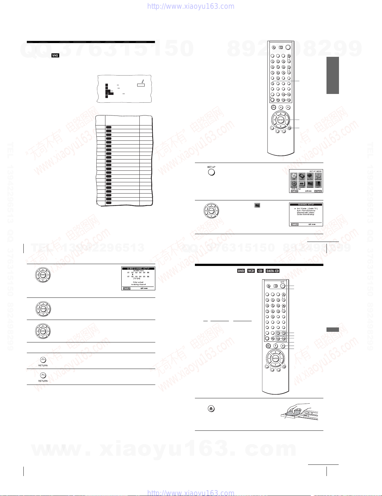
To fi nd the guide channel numbers, look at
the “Channel Line-up Chart” in the program
guide for your area that features VCR
PlusCode numbers. It usually looks like the
example to the right.
To set the guide channels, use the Channel
Line-up Chart to check that the guide channel
numbers match the TV channel your VCR
receives. For example, if HBO is listed in the
Channel Line-up Chart as channe l 33, and
your VCR receives HBO on channel 5, you
need to coordinate these numbers using the
following procedure. If the guide and TV
channel numbers are the same, you can skip
this procedure.
3
6
Example of “PlusCode”
5:30
6:30
Example of “Channel Line-up Chart”
CABLE
CH
1
3
14
MOVIE Musical (2hrs.)
2
Golf (1hr. 25min.) 42060
SPORT
CNN
WS 9974
4
23
DRAMA
5
SCIENCE AND TECHNOLOGY
(1hr. 15min.) 73457
CABLE TV
16
AMC
American Movie Classics
BRV
17
Bravo (program grid only)
20
CNN
Cable News Network
CSP
21
C-SPAN
The Disney Channel
DIS
22
DSC
The Discovery Channel
25
ESN
34
ESPN
FAM
The Family Channel
35
Home Box Office
HBO
5
LIF
Lifetime
27
MAX
Cinemax
29
MTV
Music Television
30
Nickelodeon
NIK
31
SC
38
Sports Channel
SCA
Sports Channel America
39
SHO
Showtime
45
TBS
TBS SuperStation
17
TMC
The Movie Channel
44
TNN
The Nashville Network
49
TNT
Turner Network Television
50
USA
USA Network
51
5
PlusCode
33044
Comedy (2hrs.) 17390
VCR Plus+
GUIDE CH
1
35
54
42
28
53
37
34
47
33
46
45
48
38
59
70
41
43
58
49
52
44
5
0
1
2
4
2
9
8
Press SET UP.
The “SETUP!MENU” appears.
Press V/v/B/b to select (Channel
Setup), then press ENTER.
The “CHANNEL SETUP” menu appears.
9
8
SET UP
V/v/B/b
ENTER
O RETURN
2
9
Getting Started
9
TEL 13942296513 QQ 376315150 892498299
28
Setting up the VCR Plus+® system
TEL
3
4
5
6
7
8
13942296513
Press V/v to select “Guide channel setup,”
then press ENTER.
The upper row shows VCR Plus+ guide channels and the lower row shows
TV channels or cable box out put channels. Press B/b to select the channel
number that does not match the guide chann el.
•If you made Hookup 1 (page 14) or 2 (page 16): Enter the actual number
on your TV (and VCR), then press V/v.
•If you made Hookup 3 (page 18): Enter the ca ble box output channel
(usually 2, 3, or 4), then press V/v.
Repeat steps 4 and 5 for each channel number that doe s not match.
Press O RETURN to confirm the setting.
Press O RETURN repeatedly to exit the menu.
5
1
3
6
7
3
Q
Q
Basic Operations
Playing discs
Depending on the disc, some operation s may
be different or restricted. Refer to the
operating instructions supplied with your
disc.
Before you start ...
•Turn on the DVD-VCR and your TV.
•Switch the input selector on your TV so
that the signal from the player appears on
the TV screen.
•Set TV
/ DVD·VIDEO to DVD·VIDEO,
then press SELECT DVD to control the
DVD player (page 9).
1
Press Z to open the disc tray and
place a disc on the disc tray.
1
5
Setting up the VCR Plus+® system
9
8
0
?/1
Z
m/M
C SKIP
./ >
X PAU SE
x STOP
H PLAY
2
continued
4
9
8
29
2
Basic Operations
9
9
w
w
30
Setting up the VCR Plus+® system
w
.
xia
o
y
u
1
6
1-6
3
.
c
o
with the playback side
facing down
m
continued
Playing discs
31
2
Q
Q
3
TEL 13942296513 QQ 376315150 892498299
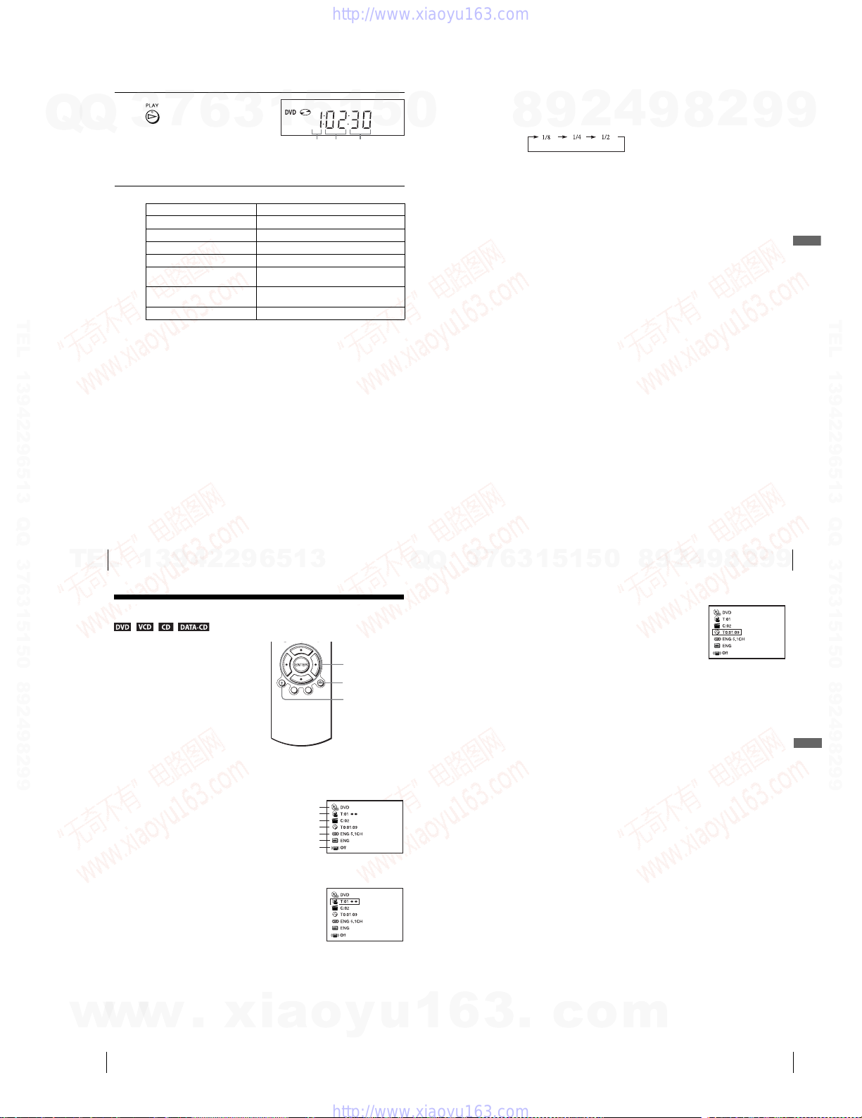
Press H PLAY.
The disc tray closes and the
DVD player starts playback.
7
6
The display window shows the
playback time
*.
Depending on the disc, a menu
may appear on the TV screen.
For DVDs, see page 70. For VIDEO CDs, see page 90.
*“– – – – –” appears whe n no disc is loaded.
Additional tasks
To Pr ess
Stop play x STOP
Pause play* X PAUS E
Resume play after pause H PLAY
Advance by frame in pause mode C SKIP
Go to the next chapter, track, or scene
in continuous play mode
Go back to the previous chapter, track,
or scene in continuous play mode
Stop play and remove the disc Z
*If you pause the DVD player for more than 5 minutes, the DVD play er will automatically stop.
To Resume playback for the current disc (Resume Play)
The DVD player remembers the point where you stopped the disc even if the DVD
player enters standby mode by pressing ?/1.
While playing a disc, press x STOP to stop playback.
1
Press H PLAY.
2
The DVD player starts playback from the point where you stopped the disc in
Step 1.
To locate a point quickly by playing a disc in fast forward or fast reverse
in continuous play mode (DVD, VIDEO CD and CD only)
Press m or M.
For DVD or Video CD, each time you press the button, the playback speed changes
as follows.
× 2 t ×4 t × 8 t × 16 t × 32 t ×128 (DVD only)
Release the button at the desired speed.
For CD, the searching speed does not change (× 8 play).
When you find the point you want, press H PLAY.
3
1
> on the remote
. on the remote
5
1
Hour Minute Second
5
0
To watch slow motion in continuous play mode (DVD and VIDEO CD
only)
Press X PAUSE, then press M SLOW y. With each press, the playback speed
changes cyclically as follows.
9
8
To r esu me normal playback, press H PLAY.
Notes
•You can change the screen type using the “SC REEN SETUP” menu. (See “Screen Setup” on
page 62)
•Do not perform VIDEO playback while playing back a disc.
•If you play a DVD or VIDEO CD that has scratches, the player may stop playback at the
point of the scratch.
•You cannot change the MP3 or the Multi Session CD playback speed.
•VIDEO CD fast forward/reverse and slow motion play cannot be paused.
•When playing a chapter with multi-angles on a DVD in slow motion, you ca nnot change the
slow motion playback speed (1/2 only).
•During CD fast forward/reverse play, no sound is output.
•The PROGRESSIVE button is not available when the DVD player is in play mode. Us e the
PROGRESSIVE button in stop mode
Notes on playing DTS* sound tracks on a CD
•When playing DTS-encoded CDs, excessive noise will be heard from the analog stereo jacks.
To av oid possible damage to the audio system, the consumer should take proper precautions
when the analog stereo jacks of the DVD player are connected to an amplification system. To
enjoy DTS Digital Surround™ playback, an external 5.1-channel decoder system must be
connected to the digital jack of the DVD player.
•Set the sound to “STEREO” using the AUDIO button when you play DTS sound tracks on a
CD (page 80).
•Do not play DTS sound tracks without first connecting the DVD player to an audio
component having a built-in DTS decoder. The DVD player outputs the DTS signal via the
DIGITAL AUDIO OUT (COAXIAL or OPTICAL) jack even if “DTS” is set to “Off” in
“AUDIO SETUP” menu (page 60), and may affect your ears or cause your speakers to be
damaged.
Notes on playing DVDs with a DTS sound track
•DTS audio signals are output only through the DIGITAL AUD IO OUT (COAXIAL or
OPTICAL) jack.
•When you play a DVD with DTS sound tracks, set “DTS” to “On” in “AUDIO SETUP”
menu (page 60).
•If you connect the player to audio equipme nt without a DTS decoder, do not set “DTS” to
“On” in “AUDIO SETUP” menu (page60). A loud noise ma y come out from the speakers,
affecting your ears or causing the speakers to be damaged.
*“DTS” and “DTS D igital Out” are trademarks of Digital Theater Sys tems, Inc.
2
4
.
9
8
2
9
9
Basic Operations
TEL 13942296513 QQ 376315150 892498299
32
TEL
Playing discs
13942296513
Guide to the on-screen display
You can check disc information during
playback.
The displayed contents differ according to
the type of disc being played.
Press DISPLAY. The following information appears; type of disc, current title/track,
chapter, counter position, voice language, subtitle language and surround setting.
Refer to “DVD Audio/Subtitle Language” on page 117 for the abbreviation of the
language.
Current title/track number
You can playback the desired title/track, chapter or counter position using this menu.
To playback the desired title/track or chapter
Press V/v to select the desired item.
1
Press B/b to change the item.
2
Press ENTER to start playback.
3
Press DISPLAY or O RETURN to turn off the menu.
4
The title/track or chapter icon will appear on the DVD playback screen followed by
the current title/track or chapter number and the counter positon.
Type of disc
Current chapter number
Counter position
Voi ce language
Subtitle language
Surround setting
V/v/B/b
ENTER
O RETURN
DISPLAY
Q
Q
3
7
9
4
2
9
8
0
5
1
5
1
3
6
To playback from the desired coun ter position
Press V/v to select the counter position icon.
1
Enter the desired position usin g the number buttons.
2
Press ENTER to start playback.
3
Press DISPLAY or O RETURN to turn off the menu.
4
Tip
•You can change the counter position information (playing time or remaining time) using
B/b
(DVD and CD only).
Notes
•The display may not change as operated depending on the disc.
•The display window continue indicating the playing time even when the counter position
information on the on-screen display is bein g changed.
8
Playing discs
9
2
9
33
Basic Operations
w
w
34
w
Guide to the on-screen display
.
xia
o
y
u
1
6
1-7
3
.
c
o
m
Guide to the on-screen display
35

0
Q
Q
2
Additional tasks
To Pr ess
Stop play x STOP
Pause play* X PAUS E
Resume play after pause X PAU SE o r H PLAY
Fast-forward the tape M during stop
Rewind the tape m during stop
Eject the tape Z
* If you pause the VCR for more than 5 minutes, the VCR will automatically resume play.
To p la y a recently watched scene
You can immediately rewind and playback the scene you want to watch again.
During playback, press REPLAY. The VCR rewinds the tape about 10 seconds in the
SP mode (about 15 seconds in the EP mode) on the counter for each press of the
button, and restarts playback.
To s kip playback
You c an skip a scene that you do not want to watch (such as a com mercial) and restart
playback.
During playback, press C C SKIP. The VCR skips the tap e 30 seconds on the
counter each time the button is pressed (up to four times) and playback is resumed.
To turn off the power while rewinding (Rewind Shut Off)
Press ?/1 while the tape is rewinding. The power will turn off but the tape will keep
rewinding until it reaches the end.
To play/search at various speeds
Playback options Operation
View the picture during fa stforward or rewind
Play at high speed • During playback, briefl y press M or m. The tape
7
3
Playing a tape
Before you start ...
Q
Q
•Turn on the DVD-VCR and your TV.
•Switch the input selector on your TV so
that the signal from the player appears on
the TV screen.
•Set TV
/ DVD·VIDEO to DVD·VIDEO,
then press SELECT VIDEO to control the
VCR (page 9).
3
7
6
3
1
?/1
Z
TRACKING +/–
CLEAR
REPLAY
MSLOWy!
m
./ >
C C SKIP
X PAU SE
x STOP
H PLAY
5
1
5
TEL 13942296513 QQ 376315150 892498299
DISPLAY
Insert a tape.
The VCR starts playing automatically if
you insert a tape with its safety tab
removed.
13942296513
36
Playing a tape
1
TEL
Press H PLAY.
The display window shows the
playback time.
8
When the tape reaches the end,
it will rewind automatically.
1
3
6
2
9
During fast-forward, hold down M. During rewind, hol d
down m.
continues to play at 5 times normal speed.
•During play back, hold down M or m. The tape
continues to play at 5 times normal speed. When you
release the button, normal playback resumes.
1
5
5
4
Hour Minute Second
8
0
9
9
8
2
2
continued
Playing a tape
9
4
8
Basic Operations
37
2
9
9
9
TEL 13942296513 QQ 376315150 892498299
9
Playback options Operation
Play in slow motion During pause, press MSLOW y.
Play frame by frame During pause, press C C SKIP.
Play at various speeds
(Shuttle play)
To r esum e normal playback
Press H PLAY.
To use the time counter
Press CLEAR at the point on the tape that you want to find later. The counter in the
display window resets to “0:00:00.” To search for the counter 0:00:00 point
automatically, see “To search for the counter 0:00:00 point” on page 95.
To display the counter on the TV screen, press DISPLAY during normal playback.
Tip
•Adjust the picture using the TRACKING +/– buttons if:
–Streaks appear while playing in slow motion.
–The picture shakes during pause.
Notes
•Tapes recorded in the LP mode on other VCRs can be played back on this VCR but the
picture quality cannot be gua ranteed.
•The counter resets to “0:00:00” whenever a tape is reinserted.
•The counter stops counting when it comes to a portion with no recording.
•When 10 hours have passed, the counter in the display window returns to “0:00:00” and the
count starts over again.
•The sound is muted during playback at various speeds.
•The picture may show noise when playing at high speed in reverse.
•While playing a tape, you can display the “SETUP MENU” but the remote commander’s
function switches to DVD automatically. Press O RETURN repeatedly to exit the menu.
•When playback does not start even if you insert a tape with its safety tab removed, set “Auto
Play” to “On” in the “VIDEO FUNCTION SETUP” menu (page 97).
•Stop disc playback while playing back a video.
•The VCR can also play S-VH S tapes. The VCR will automatically identify the type of tape
inserted in the VCR (either VHS or S-VHS). When S-VHS tapes are played in the VCR, the
enhanced resolution will not be visible on scr een; there may also be picture distortion while
playing the S-VHS tape in slow motion o r while utilizing other special playback modes. The
VCR will not record in S-VHS mode on an S-VHS tape.
During playback, press .or > SHUTTLE. You can
change the playback speed as follows.
–× 7 y –×5 y –× 3 y STILL y SLOW y PLAY
y × 2 y × 3 y × 5 y ×7
Recording TV programs
Before you start ...
•Turn on the DVD-VCR and your TV.
•Switch the input selector on your TV so
that the signal from the player appears on
the TV screen.
•Set TV
/ DVD·VIDEO to DVD·VIDEO,
then press SELECT VIDEO to control the
VCR (page 9).
•To record from a cable box, turn it on.
•Make sure the tape is longer than the total
recording time.
1
2
Insert a tape with its safety tab in place.
Press CH +/– to select the channel or line i nput video source you want to
record.
?/1
Z
CH +/–
SP/EP
TV/VIDEO
INPUT
SELECT
z REC
x STOP
H PLAY
ENTER
DISPLAY
Basic Operations
38
Playing a tape
w
w
w
.
xia
o
y
u
1
6
1-8
3
.
c
o
m
continued
Recording TV programs
39
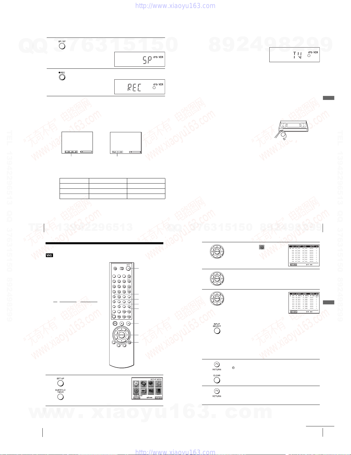
3
Q
Q
3
4
TEL 13942296513 QQ 376315150 892498299
Press SP/EP to select the tape speed, SP or EP.
EP (Extended Play) provides recording time three times as lon g as SP
(Standard Play). However, SP produces better picture and audio quality.
7
6
Press z REC to start recording.
“
REC” appears in the display window.
To s top recording
Press x STOP.
To check the remaining tape length
Press DISPLAY to display the time counter. With the display on, press DISPLAY
again to check the remaining time. The white bar indicates the current location in
relation to the entire tape length. The remaining time also appears. Press DISPLAY
to turn off the indicators.
Time counter Remaining tape length
To c heck the remaining tape length of a tape, set
FUNCTION SETUP
Maximum Recording Time
Tape Length SP EP
”
menu correctly (page 97).
T-1 20 2 hrs 6 hrs
T-1 60 2 hrs 40 mins 8 hrs
T-1 80 3 hrs 9 hrs
3
1
5
“
Tape Lengt h” in the “VIDEO
1
5
0
To watch another TV program while recording
Press TV/VIDEO to display “TV” in the display window.
1
9
8
If your TV is connected to the VCR using A/V connections, set the T V to the
2
TV’s antenna input; if not, skip this step.
Select another channel on the TV.
3
To watch a DVD while recording
Press SELECT DVD to control the DVD player.
1
Press Z and place the disc on the disc tray.
2
Press H PLAY.
3
The disc tray closes and the DVD player starts playback. The TV screen will
automatically change to the DVD playback screen.
To save a recording
To prevent accidental erasure, break
off the safety tab as illustrated. To
record on the tape again, cover the tab
hole with adhesive tape.
Tips
•To select a channel, you can use the number buttons on the remote com mander. Enter the
channel number, then press ENTER.
•You can select a video source from the LINE IN 1 or LINE-2 IN jacks using the INPUT
SELECT button.
•The display appears on the TV screen indicating in formation about the tape, but the
information will not be recorded on the tape.
•If you do not want to watch TV while recording, you can turn off the TV. When using a cable
box, make sure to leave it on.
Notes
•The remaining tape length may not be indicated accurately for short tapes such as T-20 or
T-30, or tapes recorded in the LP mode.
•It may take up to one minute for the VCR to calculate and display the remaining tape length
after you press DISPLAY.
•You cannot record a DVD to a VCR tape.
•To watch a TV program during video recording, stop disc playback.
2
4
9
8
2
Safety tab
9
9
Basic Operations
TEL 13942296513 QQ 376315150 892498299
40
TEL
Recording TV programs
13942296513
Recording TV programs using the timer
You can pr eset up to eight programs at a
time.
Before you start…
•Check that the DVD-VCR clock is set to
the correct time.
•Turn on the DVD-VCR and your TV.
•Switch the input selector on your TV so
that the signal from the player appears on
the TV screen.
•Set TV
/ DVD·VIDEO to DVD·VIDEO,
then press SELECT VIDEO to control the
VCR (page 9).
•When using a cable box, turn it on.
•Insert a tape with its safety tab in place.
Make sure the tape is longer than the total
recording time.
• If the DVD player is in play mode, you
cannot display the “SETUP MENU.” Stop
the DVD playback.
1
Press SET UP.
The “SETUP MENU” appears.
You can also use the TIMER button in VIDEO
mode, then you can skip step 2.
?/1
CLEAR
SET UP
TIMER
INPUT
SELECT
x STOP
V/v/B/b
ENTER
O RETURN
Q
Q
3
7
2
3
4
5
6
6
4
2
9
8
0
5
1
5
1
3
Press V/v/B/b to select (Set Timer
Recording), then press ENTER.
The program menu appears.
If necessary, press V/v to select the row that is to be set.
Set the channel number, start and stop time,
date, and tape speed:
1 Press b to flash each item in turn.
2 Press V/v to set each item.
To correct a setting, press B to return to that
setting and reset.
To record from a source connected to the LINE IN 1 or LINE-2 IN jacks,
press INPUT SELECT or V/v to display “L1 ” or “L2” in the “CH”
position.
To record the same program every day or the same day every week, press v
while the date is flashing. For details, see “Daily/weekly recording” on
page 44.
To u se the Auto Tape Speed function, press v to display “AUTO” in the
“SPD” position. For detail s, see “To u se the Auto Tape Speed function” on
page 44.
Press O RETURN to confirm the setting.
The indicator appears in the display window.
To enter another setting, press V/v to select the next row and repeat step 4.
Press CLEAR repeatedly to cancel the setting.
Press O RETURN repeatedly to exit the menu.
The DVD-VCR stands by for recording (timer recording will operate
properly regardless if the DVD-VCR power is on or off). When using a
cable box, leave it on.
Recording TV programs
2
8
9
9
9
41
Basic Operations
w
w
42
Recording TV programs using the timer
w
.
xia
o
y
u
1
6
1-9
3
.
c
o
m
continued
Recording TV programs using the timer
43

To s top recording
To stop the DVD-VCR while recording, press SELECT VIDEO and then press
Q
TEL 13942296513 QQ 376315150 892498299
x STOP.
Q
Daily/weekly recording
In step 4 above, press v to select the recording pattern. Each time you press v, the
indication changes as shown below. Press V to change the indication in reverse order.
MO~FR t SUN’S t MON’S t ..... t SAT’S t 1 month later t (dates count
down) t the current date
To use the Auto Tape Speed function
When you are recording a program in the AUTO mode and the remaining tape
becomes shorter than the recording time, the tape speed is automatically changed to
the EP mode. Note that some noise will appear on the picture when the tape speed is
changed. If you want to keep the tape speed, select SP. To operate this function, set
“Tape Length” in “VIDEO FUNCTION SETUP” menu correctly (page 97).
To watch another TV program after setting the timer
Press TV/VIDEO to display “TV” in the display window.
1
If your TV is connected to the VCR using A/V connections, set the TV to the
2
TV’s antenna input; if not, skip this step.
Select another channel on the TV.
3
To watch a DVD after setting the timer
Press SELECT DVD to control the DVD player.
1
Press Z and place the disc on the disc tray.
2
Press H PLAY.
3
The disc tray closes and the DVD player starts playback. The TV screen will
automatically change to the DVD playback screen.
Tips
•To set the channel, you can also use V/v.
• If the indicator appears, the ti mer settings overlap. To check, change or cancel th e program
setting, repeat the steps of “Recording TV program s using the timer” on page 42.
• If the indicator appears, this means that the VCR is currently recording this program.
•You c an also do the following tasks while the VCR is recording:
–Reset the coun ter (page 38).
–Display tape information on the TV screen (page 40).
3
7
6
3
1
5
1
5
Recording TV programs using the Dial
0
Timer
The Dial Timer function allows you to make
timer recordings of programs without turning
on your TV. Set the recording timer to record
up to eight programs that will be broadcast
within a month using the DIAL TIMER. The
recording start time and recording stop time
can be set at one minute intervals.
Before you start….
•Turn on the DVD-VCR.
•When using a cable box, turn it on .
•Insert a tape with its safety tab in place. Make sure the tape is longer than the total recording
time.
1
2
4
2
9
8
x STOP
?/1 POWER
X PAU SE
Press DIAL TIMER.
DATE indicator appears and the current date f lashes in the display window.
If the date and time are not set, MONTH indicator will appear. To set the
date and time, see “To set the clock” on page 48.
Turn DIAL TIMER to set the recording date.
9
DIAL TIMER
8
CHANNEL +/–
2
9
Basic Operations
9
TEL 13942296513 QQ 376315150 892498299
44
Recording TV programs using the timer
TEL
3
4
5
6
Press DIAL TIMER to set the start time.
“START” and the next quarter hour increment appear alternately in the
display window.
Turn DIAL TIMER to set the recording start time.
You can set the recording start time in 15 minute intervals or adjust the time
in one minute intervals by pressing the CHANNEL +/– buttons on the unit
Press DIAL TIMER to set the stop time.
“STOP” and the next quarter hour increment appear alternately in the
display window.
Turn DIAL TIMER to set the recording stop time.
You can set the recording stop time in 15 minute intervals or adjust the time
in one minute intervals by pressing the CHANNEL +/– buttons on the unit
13942296513
continued
Recording TV programs using the Dial Timer
8
0
5
1
5
1
3
6
7
3
Q
Q
7
8
.
.
9
10
11
Press DIAL TIMER.
“Current channel” flashes in the di splay window.
Turn DIAL TIMER to set the channel number.
To record from a source connected to the LINE IN 1 or LINE-2 IN jacks,
turn DIAL TIMER or press INPUT SELECT to display “L1” or “L2.”
Press DIAL TIMER.
“Current tape speed” flashes in th e display window.
Turn DIAL TIMER to set the tape speed.
Press DIAL TIMER to complete the setting.
“OK” appears in the display window for about five seconds.
The timer indicator appears in the display window and the VCR stands by
for recording. When using a cable box, leave it on.
To return to the previous step
To return to the previous step, press the CHANNEL + and – buttons on the unit at the
same time during any of the Dial Timer settings.
9
2
4
9
8
45
2
Basic Operations
9
9
w
w
w
46
Recording TV programs using the Dial Timer
.
xia
o
y
u
1
6
1-10
3
.
c
o
m
Recording TV programs using the Dial Timer
continued
47
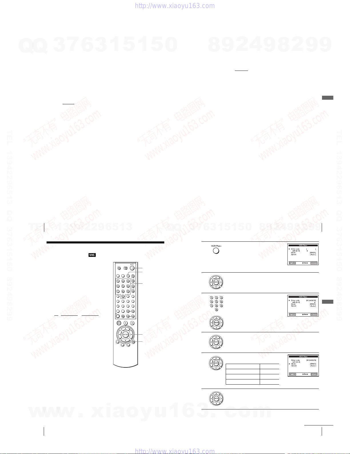
To s et the clock
Hold down DIAL TIMER so that MONTH indicator appears in the display
1
window. However, if the clock has already been set, the curr ent setting appears.
7
Q
Q
TEL 13942296513 QQ 376315150 892498299
3
2
3
4
5
6
Tips
•To cancel a Dial Timer setting, press any button other than DIAL TIMER or CHANNEL +/–
on the unit
•To check, change, or cancel the program setting, see “Checking/changing/canceling timer
settings” on page 53.
Notes
• If eight programs have already been set using the VCR Plus+ system or the manual timer
setting, “FULL” appears in the display window for about five seconds.
• If you set the clock using the Auto Clock Set feature, the clock will adjust itself to the
incoming time signal regardless of adjustments made with the Dial Timer. Be sure you have
set Auto Clock Set correctly.
• If you are setting the clock for the first time or “0:– –” appears in the display window, you
cannot set the clock to February 29
feature to set the VCR to this da y.
•The timer indicator flashes in the display window when you complete the setting in step 9 on
page 47 with no tape inserted.
•When the setting time is incorrect, “Error” appears in the display window in step 9. Set the
timer again from step 1.
6
Turn DIAL TIMER to set the month.
Press DIAL TIMER.
DAY indicator appears in the display window.
Turn and press DIAL TIMER to set the day and then the year.
After you set the year, “AM” and “12:–
window.
Turn a nd press DIAL TIMER to set the hour and minute.
When you have finished setting the time, press DIAL TIMER to start the clock.
or any button on the remote while you ar e making the setting.
1
5
3
–” appear alternately in the display
th
using the Dial Timer. Please use the Auto Clock Set
1
5
0
About the Demonstration Mode
The Dial Timer function has a Demonstration Mode that allows the user, such as a
salesperson, to enter more than eight examples of timer settings when demonstrating
9
8
the use of the Dial Timer. It cancels the FULL notice which appears if eight
programs have already been set. Do not use the Demonstrat ion Mode for making
timer recordings. Doing so may cause the settings to be inaccurate.
To activate the Demonstration Mode
Press X PAUS E on the unit
the display window for a few seconds.
To cancel the Demonstration Mode
Turn the power off and unplug the AC power cord. Although th e Demonstration
Mode is canceled, the timer settings entered while using the Demonstration Mode
will remain. Be sure to manually cancel the timer settings before you use the Dial
Timer or any other timer method after reconnecting the AC power cord (page 53).
4
2
9
while turning the DIAL TIMER. “DEMO” appears in
8
2
9
9
Basic Operations
TEL 13942296513 QQ 376315150 892498299
48
TEL
Recording TV programs using the Dial Timer
13942296513
Recording TV programs using the VCR
®
Plus+
Just enter the PlusCode number listed in the
TV program guide. The date, time an d
channel number of that prog ram are set
automatically. You can preset up to eight
programs together with the DIAL TIMER
and manual timer settings at one time.
Before you start…
•Check that the DVD-VCR clock is set to
•Turn on the DVD-VCR and your TV.
•Switch the input selector on your TV so
•Set TV
•When using a cable box, turn it on.
•Insert a tape with its safety tab in place.
• If the DVD player is in play mode, you
system
the correct time.
that the signal from the player appears on
the TV screen.
/ DVD·VIDEO to DVD·VIDEO,
then press SELECT VIDEO to control the
VCR (page 9).
Make sure the tape is longer than the total
recording time.
cannot display the “SETUP MENU.” Stop
the DVD playback.
?/1
VCR Plus+
Number
buttons
M/m/</,
ENTER
O RETURN
Q
Q
3
7
1
2
3
4
5
6
5
1
5
1
3
Press the VCR Plu s+ button.
Press V/v to select “Enter code.”
Press the number buttons to enter the
PlusCode number.
To correct a setting, press B to return to that
setting and reset.
Press V/v to select “Mode.”
Press B/b to select ONCE, MO~FR, or
Weekly:
To record Select
Only once ONCE
Everyday Monday to Friday MO~FR
Once a week Weekly
0
Recording TV programs using the Dial Timer
2
9
8
4
9
8
2
9
9
49
Basic Operations
w
w
50
w
Recording TV programs using the VCR Plus+® system
.
xia
o
y
u
1
6
1-11
6
3
.
c
Press V/v to select “Speed.”
o
m
Recording TV programs using the VCR Plus+® system
continued
51

7
Q
8
9
10
TEL 13942296513 QQ 376315150 892498299
52
Recording TV programs using the VCR Plus+® system
TEL
2
3
Press B/b to select the tape speed, Auto, SP,
or EP.
Q
Press ENTER to confirm the setting.
To enter another setting, repeat steps 1 to 7.
Press O RETURN to exit the menu.
Press ?/1 to turn off the VCR.
The timer indicator appears in the display window and the VCR stands by
for recording. When using a cable box, leave it on.
To s top recording
To stop the VCR while recording, press x STOP.
To use the DVD-VCR after setting the timer
To u se the DVD-VCR before a timer recording begins, just press ?/1. The timer
indicator disappears from the display window and the DVD-VCR switches on.
Remember to press ?/1 to reset the VCR to the timer recording standby mode after
using the VCR.
You can also do the following tasks while the VCR is recording:
•Reset the counter (page 38).
•Display tape information on the TV screen (page 40).
•Check the timer settings (page 53).
•Watch another TV program (page 41).
Tip
•To check, change or cancel the program setting, see “Checking/cha nging/canceling timer
settings” on page 53.
Note
• If the VCR does not accept the PlusCode number, this means that:
–The PlusCode number is inco rrect.
–ONCE, MO~FR, or Weekly was selected incorrectly. You cannot select MO~FR or Weekly
for a program that airs more than seven days ahead.
Correctly set the PlusCode number again from step 2.
•When the PlusCode number is incorrect, “Invalid Code” will appear in the display.
3
7
6
3
1
5
13942296513
Press V/v/B/b to select “Set Timer Recording”, then press ENTER.
•If you want to change a setting, go on to the next step.
•If you do not need to change the settings, press O RETURN repeatedly
to exit the menu, then turn off the VCR to return to recording standby.
Press V/v to select setting you want to change
or cancel.
•To change the setting, press B/b to flash the
item you want to change, and press V/v to
change it.
•To cancel the setting, press CLEAR.
1
5
Checking/changing/canceling timer
0
settings
1
7
3
Q
Q
Advanced Hookups
A/V Receiver hookup
A Use this hookup if your A/V receiver has a Dolby* Surround (Pro
Logic) decoder and 3 to 6 speakers
You can enjoy the Dolby Surround effects only when playi ng Dolby Surround audio
or multi-channel audio (Dolby Digital) discs.
∗ Manufactured un der license from Dolby Laboratories. “Dolby,” “Pro Logic,” and the double-
D symbol are trademarks of Dolby Laboratories .
4
2
9
8
Press SET UP when the DVD player is in stop
mode.
The “SETUP MENU” appears.
You can also use the TIMER button in VIDEO
mode, then you can skip step 2.
Checking/changing/canceling timer settings
0
5
1
5
1
3
6
DVD- VCR
9
8
9
8
?/1
CLEAR
SET UP
TIMER
V/v/B/b
ENTER
O RETURN
continued
4
2
2
9
8
Basic Operations
53
2
9
9
9
TEL 13942296513 QQ 376315150 892498299
9
4
5
w
54
Checking/changing/canceling timer settings
Press O RETURN to confirm the setting.
The indicator appears in the display window.
Press O RETURN repeatedly to exit the menu.
The DVD-VCR stands by for recording (you do not have to turn off the
DVD-VCR). When using a cable box, leave it on.
When the timer settings overlap
The program that starts first has priority and the second program starts recording only
after the first program has finished. If the programs start at the same time, the
program listed first in the menu has pr iority.
Program 1
Program 2
w
w
Will be cut off
.
xia
to LINE OUT L/R (AUDIO)
l: Signal flow
Rear (L)
Note
•When connecting 6 speakers, replace the monaural rear speaker with a center spe aker, 2 rear
o
y
u
1
6
1-12
(red)
(white)
to audio input
[Speakers]
Rear (R)
Subwoofer
speakers and a subwoofer.
3
.
Stereo audio cord
(not supplied)
Amplifier (receiver) with Dolby
Surround decoder
Center
c
o
(red)(white)
Rear (mono)
m
[Speakers]
Front (L)
Front (R)
continued
A/V Receiver hookup
Advanced Hookups
55
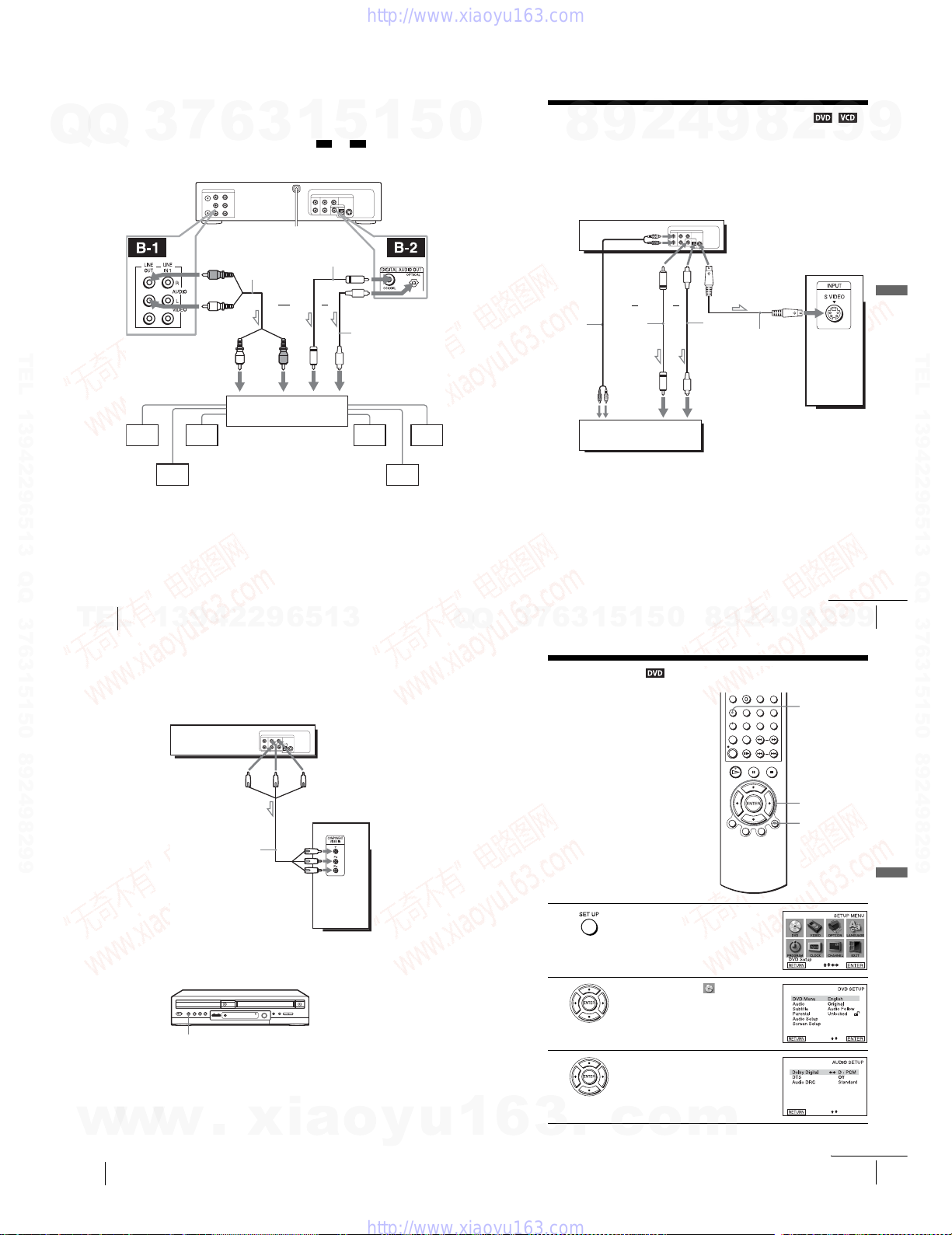
B Use this hookup if your A/V reciever has a Dolby Digital or DTS*
decoder, a digital input jack and 6 speakers
This connection will allow you to use the Dolby Digital or DTS decoder function of
your AV amplifier (receiver). You are not able to enjoy the surround sound effects of
7
Q
Q
TEL 13942296513 QQ 376315150 892498299
3
this player. You must make connections using and .
∗ “DTS” and “DTS Digital Out” are trademarks of Digital Theater Systems, Inc.
to LINE OUT L/R (AUDIO)
l: Signal flow
[Speakers]
Rear (L)
Rear (R)
Note
•After you have completed the connection, be sure to set “Dolby Digital” to “Dolby Digital”
and “DTS” to “On” in “AUDIO SETUP” menu (page 60). Otherwise, no sound or a loud
noise will come from the s peakers.
6
DVD-VC R
(red)
Stereo audio cord
(not supplied)
(white)
to audio input
AV amplifier (receiver) having
a decoder
Subwoofer Center
3
and
1
Coaxial digital cord
(not supplied)
(red)(white)
5
B-1 B-2
or
to coaxial or optical
digital input
1
to DIGITAL OUT
(COAXIAL or OPTICAL)
Optical digital cord
(not supplied)
Remove jack cap
before connecting
[Speakers]
Front (L)
Front (R)
5
0
S-Video/Component Video hookup
4
2
9
8
Make audio connections using the LINE OUT AUDIO L/R jacks or DIGITAL AUDIO OUT
(OPTICAL or COAXIAL) jacks on the right side of the DVD-VCR when you use S-VIDEO/
Component Video hookup.
A Use this hookup if your TV has an S VIDEO input jack
Connect an S VIDEO cord (not supplied). You will enjoy high quality images.
DVD- VCR
or
Audio cord
(not supplied)
Coaxial
digital cord
(not supplied)
to audio
input
TV or AV amplifier
Notes
•Set “Video Out” to “S-Video” in the “SCREEN SETUP” menu (page 64) to view pictures
from the S VIDEO jack.
•The connection using S VIDEO OUT jack is only for the DVD player.
or
9
l : Signal flow
(DVD only)
Optical digital
cord (not
supplied)
Remove jack
cap before
connecting
to coaxial or optical
digital input
8
S VIDEO cord
(not supplied)
2
9
TV
9
Advanced Hookups
TEL 13942296513 QQ 376315150 892498299
56
A/V Receiver hookup
TEL
w
w
58
S-Video/Component Video hookup
13942296513
B Use this hookup if your TV has component video input jacks
Connect your TV via the COMPONENT VIDEO OUT jacks using a component
video cord (not supplied) or three video cords (not supplied) of the same kind and
length. You will enjoy accurate color reproduction and high quality images.
See page 55 for audio connections.
DVD-VC R
(blue) (red)
Component video cord
(not supplied)
l : Signal flow
(DVD only)
If your TV accepts progressive (480p) format signals, you must use this connect ion
and then press the PROGRESSIVE button on the front panel when the DVD player is
in stop mode to accept progressive video signals. The PROGRESSIVE indicator
lights up in blue when the DVD player outputs progressive signals.
PROGRESSIVE button/indicator
Notes
•Set “Video Out” to “Component” in the “SCREEN SETUP” menu (page64) to view pictures
from the component video jacks.
•The connection using COMPONENT VIDEO OUT jack is only for the DVD player.
•The PROGRESSIVE button is not available when the DVD player is in play mode. Use the
PROGRESSIVE
w
button in stop mode.
.
xia
(green)
TV
(green)
(blue)
(red)
o
y
u
Q
Q
1
3
6
5
1
5
1
3
6
7
DVD Settings and Adjustments
Audio Setup
“Audio Setup” allows you to set the sound
according to the playback and connectio n
conditions.
1
2
3
3
Press SET UP when the DVD player is in stop
mode.
The “SETUP MENU” appears.
Press V/v/B/b to select (DVD Setup),
then press ENTER.
The “DVD SETUP” menu appears.
Press V/v to select “Audio Setup,” then press
ENTER.
.
c
o
0
m
8
S-Video/Component Video hookup
9
4
2
9
2
8
SET UP
V/v/B/b
ENTER
O RETURN
continued
9
continued
Audio Setup
9
57
DVD Settings and Adjustments
59
1-13

4
Q
5
6
TEL 13942296513 QQ 376315150 892498299
Press V/v to select the setup item from the displayed list:
“Dolby Digital,” “DTS,” or “Audio DRC.”
Q
Press B/b to select an item, then press O RETURN to confirm the setting.
Press O RETURN repeatedly to exit the menu.
Menu choices
•Dolby Digital (DVD only)
Selects the type of Dolby Digital signal.
The default setting is indicated in bold print.
D-PCM Select thi s when the player is connected to an audio component
Dolby Digital Select this when th e player is connected to an audio c omponent
•DTS (DVD only)
Selects whether or not to output DTS signals.
The default setting is indicated in bold print.
Off Select this when the play er is connected to an audio compo nent
On Select t his when the player is connected to an audio component
•Audio DRC (Dynamic Range Control) (DVD only)
Makes the sound clear when the volume is turned down when playing a DVD that
conforms to “Audio DRC.” This affects the output from the following jacks:
–LINE OUT AUDIO L/R jacks
–DIGITAL AUDIO OUT (OPTICAL or COAXIAL) jack only when “Dolby
Digital” is set to “D-PCM”.
The default setting is indicated in bold print.
Standard Normally select this positi on.
TV Mode Makes the low sounds clear even if you turn the volume down.
3
7
6
3
lacking a built-in Dolby Digital decoder.
with a built-in Dolby Digital deco der.
lacking a built-in DTS decoder.
with a built-in DTS decoder.
1
5
1
5
0
Notes
•If you select surround setting while playing a DVD, the player does not output Dolby Digital
signals from the DIGITAL AUDIO OUT (OPTICAL or COAXIAL) jack (when you set
“Dolby Digital” to “D-PCM”).
•If you connect a component that does not conform to the selected audio signal, a loud noise
(or no sound) will come out from the speakers, affecting your ears or causing the speakers to
be damaged.
8
9
2
4
9
8
2
9
DVD Settings and Adjustments
9
TEL 13942296513 QQ 376315150 892498299
60
Audio Setup
TEL
Screen Setup
“Screen Setup” allows you to set the screen
according to the playback a nd connection
conditions.
1
2
3
13942296513
Press SET UP when the DVD player is in stop
mode.
The “SETUP MENU” appears.
Press V/v/B/b to select (DVD Setup),
then press ENTER.
The “DVD SETUP” menu appears.
Press V/v to select “Screen Setup,” then press
ENTER.
SET UP
V/v/B/b
ENTER
O RETURN
Q
Q
8
0
5
1
5
1
3
6
7
3
4
5
6
Press V/v to select the setup item from the displayed list:
“TV Type,” “Black Level,” or “Video Out.”
Press B/b to select an item, then press O RETURN to confirm the setting.
Press O RETURN repeatedly to exit the menu.
Menu choices
•TV Type (DVD only)
Selects the aspect ratio of the connected TV (4:3 standard or wide).
The default setting is indicated in bold print.
4:3 Letter Box Select this when you connect a 4:3 screen TV. Displays a wide
4:3 Pan Scan Select this when you connect a 4:3 screen TV. Automatically
16:9 Select this when you connect a wide-screen TV or a TV with a wide
•Black Level
You can enhance the black level by increasing the brightness and contrast when
viewing DVDs with the PROGRESSIVE indicator turned off.
The default setting is indicated in bold print.
On Increases the contrast.
Off Stops the increase of the contrast.
picture with bands on the upper and lower portions of the scre en.
displays the wide picture on the entire screen a nd cuts off the
portions that do not fit.
mode function.
4:3 Pan Scan4:3 Letter Box 16:9
9
2
Audio Setup
9
4
8
61
2
DVD Settings and Adjustments
9
9
62
w
Screen Setup
w
w
.
xia
o
y
u
1
6
1-14
3
.
c
o
m
continued
Screen Setup
63
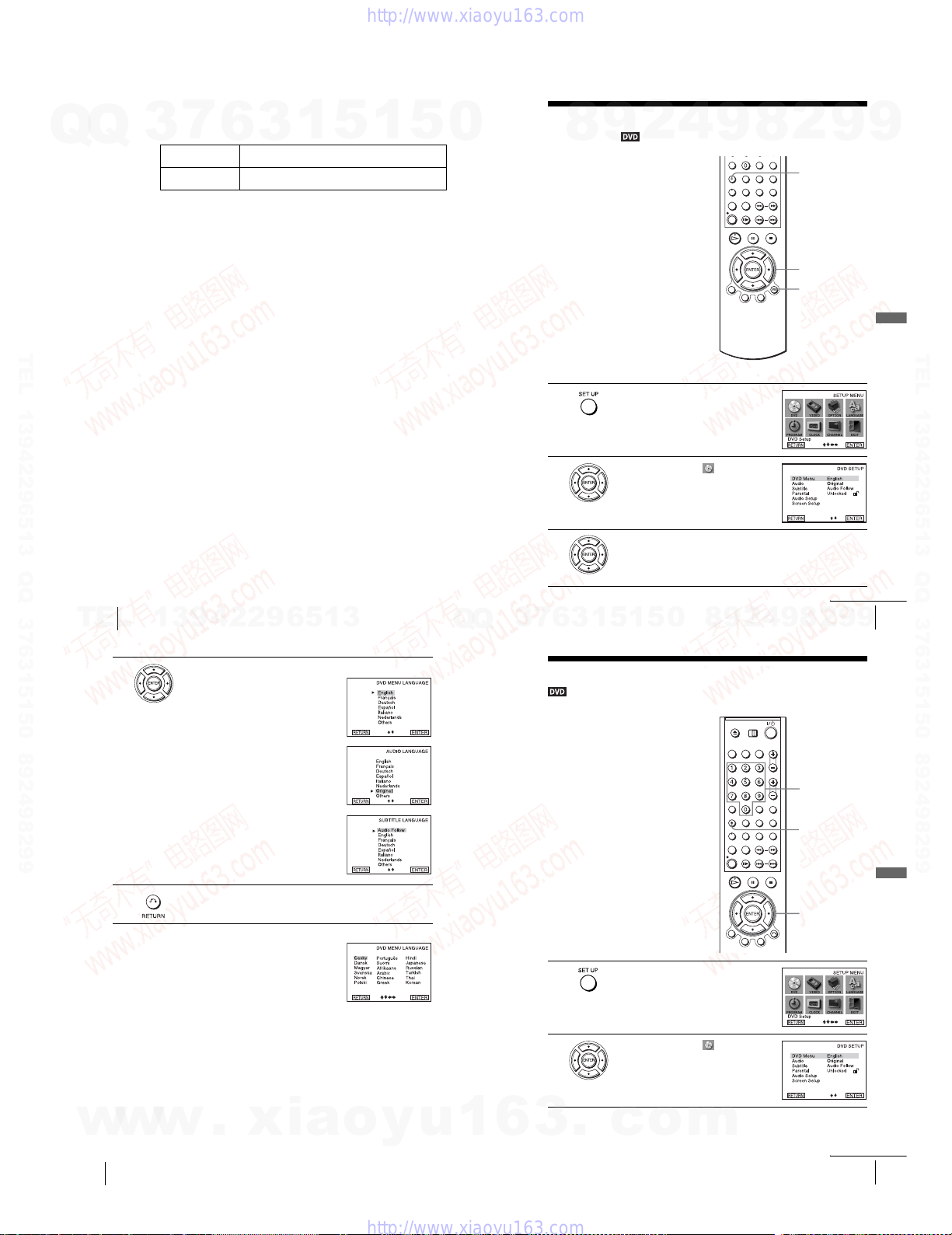
•Video Out
You must set this setting when you use S VIDEO OUT or COMPONENT VIDEO
OUT jacks to connect to the TV.
The default setting is indicated in bold print.
7
Q
Q
TEL 13942296513 QQ 376315150 892498299
3
S-Video Select this when you use the S VIDEO OUT jack on the rear panel
Component Select this when you use the COMPONENT VIDEO OUT jacks
Tip
•You c an select the type of signal output from the COMPONENT VIDEO OUT jacks.
When you press the PROGRESSIVE button on the front panel when the DVD player is in
stop mode, progressive signal is selected and the PROGRESSIVE indicator lights up in b lue.
Select this when you have a TV that can accept progressive signal.
When you are connected to a standard (interlace format) TV, turn off the PROGRESSIVE
indicator.
Notes
•Playback settings stored in the disc take priority over the “DVD SETUP” menu settings and
not all the functions described may work.
•Depending on the DVD, “4:3 Letter Box” may be selected automatically instead of “4:3 Pan
Scan” or vice versa.
•The connection using S VIDEO OUT or COMPONENT VIDEO OUT jacks is only for the
DVD player.
• If you select progressive signal when you co nnect the DVD player to a TV that cannot accep t
the signal in progressive format, the image quality will deteriorate. In this case, press the
PROGRESSIVE button to turn off the PROGRESSIVE indicator.
•You can output progressive signal only from COMPONENT VIDEO OUT jacks. If you turn
on the PROGRESSIVE indicator when you set “Video Out” to “S-video”, COMPONENT
VIDEO OUT takes priority over S VIDEO OUT.
•The PROGRESSIVE button is not available when the DVD player is in play mode. Use the
PROGRESSIVE button in stop mode.
6
to connect to the TV.
on the rear panel to connect to the TV.
3
1
5
1
5
0
Setting the display or sound track
language
You can set various languages for th e disc’s
menu, sound track or subtitle.
1
Press SET UP when the DVD player is in stop
mode.
The “SETUP MENU” appears.
2
9
8
4
9
8
2
9
SET UP
V/v/B/b
ENTER
O RETURN
9
DVD Settings and Adjustments
TEL 13942296513 QQ 376315150 892498299
64
TEL
4
5
Screen Setup
13942296513
Press V/v to select the desired language, then press ENTER.
•DVD MENU LANGUAGE
Yo u ca n select the desired language for the
disc’s menu.
•AUDIO LANGUAGE
Switches the language of the sound track .
When you select “Original,” the language
given priority in the disc is selected.
•SUBTITLE LANGUAGE
Switches the language of the subtitle
recorded on the DVD.
When you select “Audio Follow,” the
language for the subtitles changes according
to the language you selected for t he sound
track.
Press O RETURN repeatedly to exit the menu.
Tip
If you select “Others” in step 4, an additional language
menu appears. Press V/v/B/b to select the desired
language, then press ENTER.
Notes
•When you select a language that is not recorded on the DVD in step 4, one of the recorded
languages will be automatically selected.
•Playback settings stored in the disc take priority over the DVD SETUP settings a nd not all the
functions described may work.
Q
Q
2
3
6
7
3
Parental Control (limiting playback by children)
Playback of some DVDs can be limited
according to a predetermined level such as
the age of the users. The “Parental Control”
function allows you to set a playback
limitation level.
1
2
Press V/v/B/b to select (DVD Setup),
then press ENTER.
The “DVD SETUP” menu appears.
Press V/v to select the language setup item from the displayed list:
“DVD Menu,” “Audio,” or “Subtitle.”
Then press ENTER.
Setting the display or sound track language
9
8
0
5
1
5
1
3
Press SET UP when the DVD player is in stop
mode.
The “SETUP MENU” appears.
Press V/v/B/b to select (DVD Setup),
then press ENTER.
The “DVD SETUP” menu appears.
2
4
9
8
Number
buttons
SET UP
V/v/B/b
ENTER
continued
2
9
9
65
DVD Settings and Adjustments
w
w
w
66
Setting the display or sound track language
.
xia
o
y
u
1
6
1-15
3
.
c
o
m
Parental Control (limiting playback by children)
continued
67
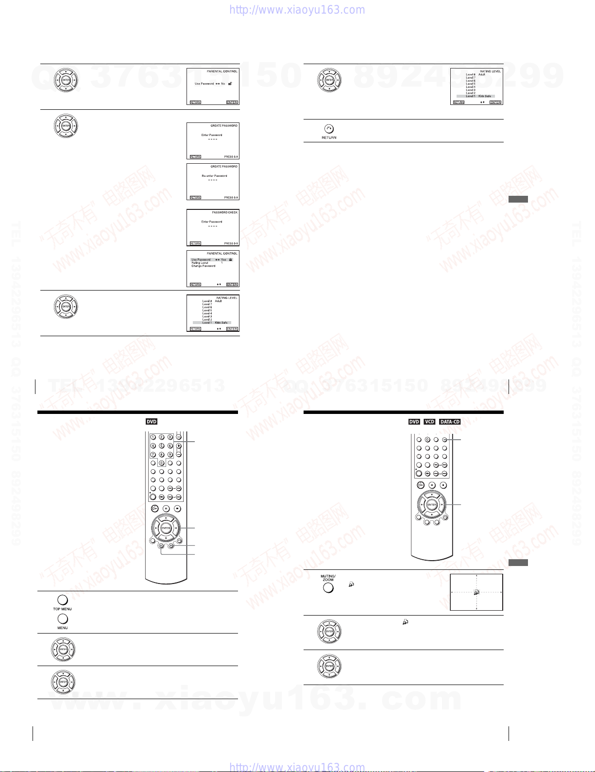
3
Q
4
TEL 13942296513 QQ 376315150 892498299
5
Press V/v to select “Parental,” then press
ENTER.
Q
Press b to select “Yes”.
•If you have not entered a password
•When you have already registered a
Press V/v to select “Rating Level,” then press
ENTER.
7
3
The display for registering a new pass word
appears.
Enter a 4-digit password using the numb er
buttons.
The display for confirming the password
appears.
Re-enter the password.
password
The display for entering the password appears.
Enter a 4-digit password using the numb er
buttons.
6
3
1
5
1
5
0
6
7
To change the password
Select “Change Password” in step 4.
1
The display for entering a new password appears.
Enter a new 4-digit password using the number buttons.
2
The display for confirming the password appears.
Re-enter the new password.
3
To turn off the Parental Control function
Set “Use Password” to “No” in Step 4.
To play a disc for which Parental Control is set
Insert the disc, then press H PLAY.
1
The display for entering your password appea rs.
Enter your 4-digit password using the number buttons.
2
The player starts playback.
If you forget your password
Remove the disc and turn off the DVD-VCR.
1
Turn o n the DV D-VCR again with no disc in the unit.
2
Hold down m and M on the front panel simultaneously for 5 seconds.
3
“reset ok” appears on the screen.
Turn off the DVD-VCR.
4
The password is cleared.
To create a new password, follow step 4 on page 68.
5
Notes
•When you play DVDs which do not have the Parental Control function, playback cannot be
limited on this player.
•All the ratings high er than the level you select will be blocked.
•Write your password down and keep it in a safe place in case you forget it.
Press V/v to select the level you want, then
press ENTER.
The options are as follows.
Level 8 (Adult) y Level 7 y Level 6 y
Level 5 y Leve l 4 y Level 3 y Level 2
y Level 1 (Kids Safe)
The lower the value, the stricter the limitation.
Press O RETURN repeatedly to exit the menu.
8
9
2
4
9
8
2
9
DVD Settings and Adjustments
9
TEL 13942296513 QQ 376315150 892498299
68
Parental Control (limiting playback by children)
TEL
DVD Additional Operations
Using the DVD’s menu
A DVD is divided into long sections of a
picture or a music feature called “titles.”
When you play a DVD which contains
several titles, you can select the title you
want using the TOP MENU button.
When you play DVDs that allow you to
select items such as the language for the
subtitles and the language for the sound,
select these items using the MENU button.
1
2
3
13942296513
Press TOP MENU or MENU
The disc’s menu appears on the TV screen.
The contents of the menu vary from disc to disc.
Press V/v/B/b to select the item you want to play or change.
You can also use the number buttons to select the item.
Press ENTER.
Parental Control (limiting playback by children)
5
1
5
1
3
6
7
3
Q
Q
Zooming into a scene
Number
buttons
V/v/B/b
ENTER
MENU
TOP
MENU
.
You can zoom into a scene during playback
or still mode. To zoom into a JPEG image,
see “Playing JPEG image files” on page 87.
1
2
3
Press ZOOM.
“” appears.
Press V/v/B/b to move “ ” to the po sition where you want to zoom in.
Press ENTER repeatedly to change the magnification.
Each time you press the button, the magnification changes as shown below.
2× t 4× t 2× t normal magnification
0
8
9
4
2
ZOOM
V/v/B/b
ENTER
9
8
69
2
DVD Additional Operations
9
9
w
70
Using the DVD’s menu
Note
w
•Depending on the DVD, you may not be able to use the TOP MENU button.
w
.
xia
Notes
•You cannot use 4
o
y
u
1
1-16
•The zoom function may not work depending on the DVD.
6
× magnification when you play VIDEO CDs.
3
.
c
o
m
Zooming into a scene
71

Changing the angles
Q
Q
If various angles (multi-angles) for a scene
are recorded on the DVD, “ ” appears in
the display when you press ANGLE during
playback. This means that you can change
the viewing angle.
TEL 13942296513 QQ 376315150 892498299
1
2
7
3
Note
•Depending on the DVD, you may not be able to change the angles even if multi-angles are
recorded on the DVD.
6
Press ANGLE during playback.
The angle number appears on the display.
The number after the slash indicates the total
number of angles.
Press B/b repeatedly to select the angle number.
The scene changes to the selected angle.
3
1
5
1
ANGLE
B/b
5
0
Displaying the subtitle
4
2
9
8
If subtitles are recorded on the disc, you can
change the subtitles or turn them on and off
whenever you want while playing a DVD.
1
2
3
Press SUBTITLE during playback.
Press B/b repeatedly to select the language.
Depending on the DVD, the choice of language varies.
Refer to “DVD Audio/Subtitle Language” on page 117 for the abbreviation
of the language.
Press V/v repeatedly to select “On.”
To turn off the subtitles
Select “Off” in step 3.
Note
•Depending on the DVD, you may not be able to change the subtitles even if multilingual
subtitles are recorded on it. You also may not be able to turn them off.
9
8
2
SUBTITLE
V/v/B/b
ENTER
9
9
DVD Additional Operations
TEL 13942296513 QQ 376315150 892498299
72
Changing the angles
TEL
13942296513
Var ious play mode functions (Program play,
Shuffle play, Repeat play)
You can set the following play modes:
•Program play (page 74)
•Shuffle play (page 76)
•Repeat play (page 77)
Note
•The play mode is canceled when:
–you open the disc tray
–the player enters standby mode by pressing [/1.
Creating your own program (Program play)
You can play the contents of a disc in the
order you want by arranging the order of the
tracks on the disc to create your own
program. You can program up to 20 tracks.
Number
buttons
CLEAR
REPEAT
H PLAY
V/v/B/b
ENTER
Q
Q
3
7
5
1
3
6
1
2
3
4
5
Press REPEAT when the DVD player is in stop
mode.
Press B/b to select “PROGRAM”, then press
ENTER.
Press V/v/B/b to select the track number you
want to program, then press ENTER.
You ca n a lso use the number buttons to enter
the track number.
To p rogr am other tracks, repeat step 3.
The programed track numbers are d isplayed in the selected order.
Press H PLAY to start program play.
Program play starts.
When the program ends, you can restart the same program again by
pressing H PLAY.
To stop program play
Press CLEAR.
To change or cancel a program
Follow steps 1 and 2 of “Creating your own progra m (Program play).”
1
Press CLEAR.
2
The last programed number is canceled.
Follow step 3 for new programing.
3
1
5
0
8
9
2
4
9
Displaying the subtitle
8
2
9
9
73
DVD Additional Operations
w
w
w
74
Various play mode functions (Program play, Shuffle play, Repeat play)
.
xia
o
y
u
1
6
1-17
3
.
c
o
m
Various play mode functions (Program play, Shuffle play, Repeat play)
continued
75
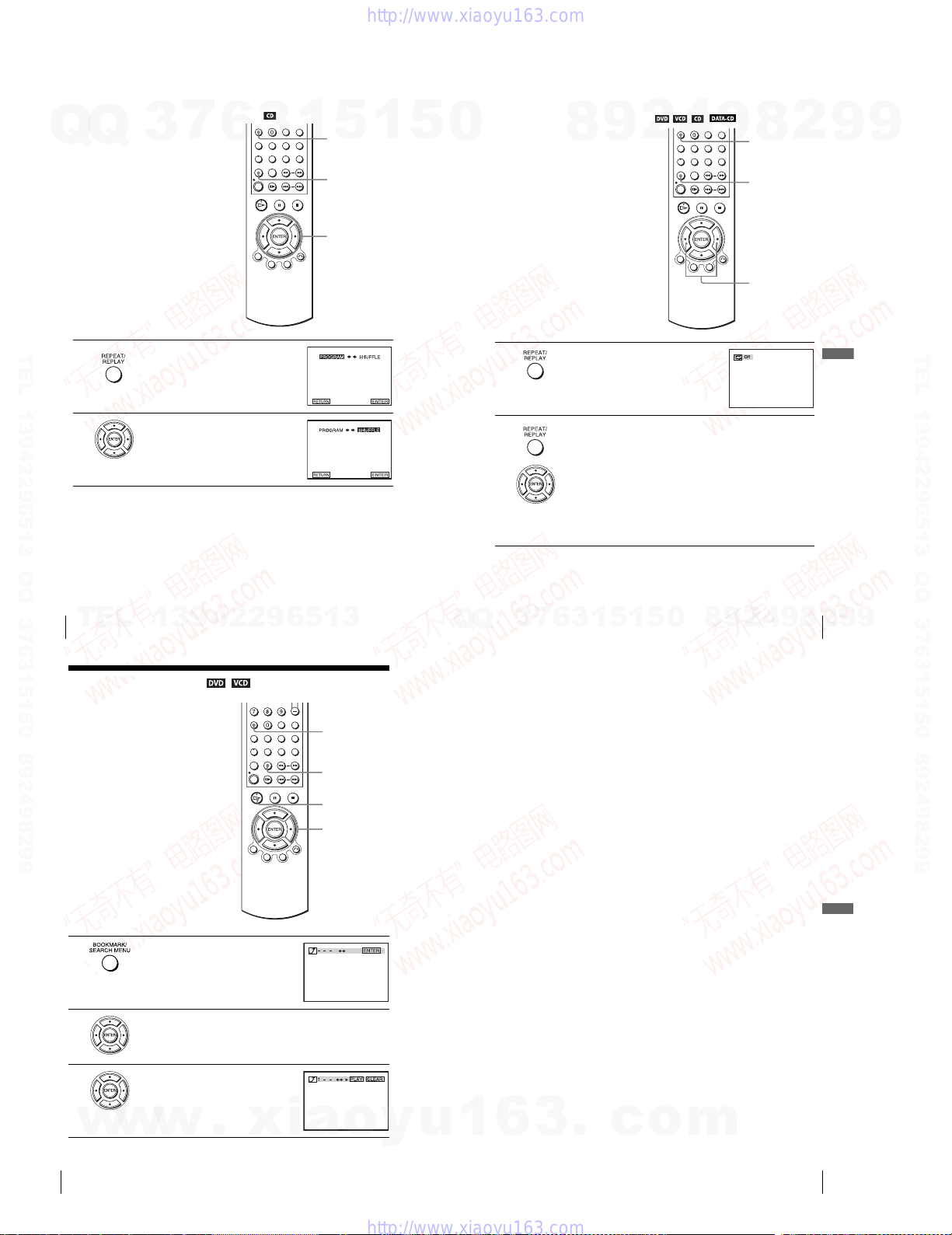
Playing in random order (Shuffle play)
You ca n shuffle the playback order o f tracks.
Subsequent “shuffling” may produce a
Q
Q
different playing order.
TEL 13942296513 QQ 376315150 892498299
1
2
To return to normal play
Press CLEAR.
7
3
Press REPEAT when the DVD player is in stop
mode.
Press B/b to select “SHUFFLE”, then press
ENTER.
6
3
1
5
CLEAR
REPEAT
V/v/B/b
ENTER
1
5
0
Playing repeatedly (Repeat play)
You can play all of the titles or tracks on a
disc or a single title, chapter, or track
repeatedly.
1
2
To return to normal play
Select “Off” or press CLEAR in step 2.
4
2
9
8
Press REPEAT during playback.
Press REPEAT or B/b repeatedly to select the item to be repeated.
When playing a DVD
•Chapter: repeats the current chapter.
•Title: repeats the current title on a disc.
When playing a VIDEO CD or CD
•Track: repeats the current track.
•Disc: repeats all of the tracks.
When playing a DATA CD (MP3 audio)
•Track: repeats the current track.
9
8
CLEAR
REPEAT
B/b
2
9
DVD Additional Operations
9
TEL 13942296513 QQ 376315150 892498299
76
Various play mode functions (Program play, Shuffle play, Repeat play)
TEL
Using bookmarks
You can store scen es in the player’s memory
as bookmarks.
You can set up to three bookmarks.
Select “MENU OFF” before setting up
bookmarks on a VIDEO CD (see “Playing
VIDEO CDs with “MENU ON/OFF”
Functions” on page 90).
1
2
13942296513
Press BOOKMARK during playback.
Three bookmark placeholders (- - - ) appear
next to the bookmark icon.
Press B/b to select one of the placeholders.
CLEAR
BOOKMARK
H PLAY
B/b
ENTER
Q
Q
Various play mode functions (Program play, Shuffle play, Repeat play)
5
1
3
6
7
3
To c an cel the bookmark
Press CLEAR after step 3.
To exit the Bookmark menu
Press BOOKMARK.
To playback the scene where you ins ert a bookmark
Press BOOKMARK during playback.
1
Press B/b to select the bookmark placeholder, then press H PLAY to play the
2
bookmark.
Note
•Depending on the DVD, you may not be able to use the bookmark function .
1
5
0
8
9
2
4
9
8
77
2
9
9
DVD Additional Operations
3
78
Using bookmarks
w
w
Play the DVD scene you want, then press
ENTER.
The selected placeholder changes to a numb er
(1, 2 or 3).
w
.
xia
o
y
u
1
6
1-18
3
.
c
o
m
Using bookmarks
79
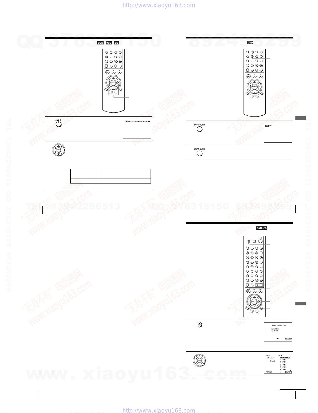
Changing the sound
7
Q
Q
TEL 13942296513 QQ 376315150 892498299
3
When playing a DVD recorded in multiple
audio formats (PCM, Dolby Digital, or
DTS), you can change the audio for mat. If
the DVD is recorded with multilingual
tracks, you can also change the language.
With CDs, DATA CDs, or VIDEO CDs, you
can select the sound from the right or left
channel and listen to the sound of the
selected channel through both the right and
left speakers. For example, when playing a
disc containing a song with the vocals on the
right channel and the instruments on the left
channel, you can hear the instruments from
both speakers by selecting the left channel.
1
2
6
Press AUDIO during playback.
Press B/b repeatedly to select the desired language/audio setting.
•When playing a DVD
Depending on the DVD, the choice of language varies.
Refer to “DVD Audio/Subtitle Language” on page 117 for the
abbreviation of the language.
•When playing a VIDEO CD or CD
The default setting is indicated in bold print.
STEREO
Left The sound of the left channel (monaural)
Right The sound of the right channel (monaural)
3
1
5
The standard stereo sound
1
AUDIO
B/b
5
0
Virtual surround setting
9
8
When you connect a stereo TV or 2 front
speakers, SURROUND lets you enjoy surround
sound effects by using sound imaging to create
virtual rear speakers from the sound of the front
speakers without using actual rear speakers.
This function is designed to work with the LINE
OUT AUDIO L/R jacks.
1
2
Press SURROUND during playback.
Press SURROUND repeatedly to select “On.”
To cancel the setting
Select “Off” in step 2.
2
4
9
8
2
SURROUND
9
9
DVD Additional Operations
TEL 13942296513 QQ 376315150 892498299
80
TEL
Changing the sound
13942296513
Notes
•When the playing signal does not contain a signal for the rear speakers, the surround effects
will be difficult to hear.
•When you activate the surround effect, turn off the surround setting of the conne cted TV or
amplifier (receiver).
•Make sure that your listening position is between and at an equal distance from your
speakers, and that the speakers are located in similar surroundings.
• If you use the DIGITAL AUDIO OUT (OPTICAL or COAXIAL) jack and set “Dolby
Digital” to “Dolby Digital” or “DTS” to “On” in “AUDIO SETUP” menu, sound will come
from your speakers but it will not have the surround effect.
•Certain audio features of this p roduct manufactured under a license from De sper Products,
Inc. Spatializer
Products, Inc.
®
, VBX™ and the circle-in-square device are trademarks owned by Desper
Q
Q
8
0
5
1
5
1
3
6
7
3
Playing an MP3 audio track
You can play back DATA CDs (CD-ROMs/
CD-Rs/CD-RWs) recorded in MP3 (MPEG1
Audio Layer 3) format.
1
2
Press Z and place a DATA CD on the disc tray,
then press Z to close the tray.
When you load a DATA CD which contains
MP3 audio tracks and JPEG image files,
“Select a Media Type” menu appears.
If you load a DATA CD which contains only
MP3 audio files, the MP3 display appea rs.
Then you can skip step 2.
Press V/v to select “MP3”, then press ENTER.
9
2
4
9
continued
Virtual surround setting
8
9
2
Z
./ >
H PLAY
V/v/B/b
ENTER
O RETURN
9
81
DVD Additional Operations
w
w
82
w
Virtual surround setting
.
xia
o
y
u
1
6
1-19
3
.
c
o
m
continued
Playing an MP3 audio track
83

3
Q
4
5
TEL 13942296513 QQ 376315150 892498299
Press V/v or ./ > to select the desired track, then press ENTER.
The selected track starts playing.
When a track or album is being played, its title is shaded. The playing track
Q
number appears on the display window.
To change the album, press O RETURN.
Press V/v to select an album, then press
ENTER.
The list of tracks contained in the album
appears.
To select a track, repeat step 2.
To go to the next or previous page
Press b or B.
To return to the previous display
Press O RETURN.
To return to the “Select a Media Type” menu
Press x STOP twice, then press TOP MENU.
To turn off the display
Press x STOP, then press O RETURN repeatedly.
Notes
•Only the letters in the alphabet and numb ers can be used for album or track names. Anything
else is displayed as an asterisk.
•Up to 10 alphanumeric characters can be displayed for album or track names.
•ID3 tags cannot be displayed.
3
7
6
3
1
5
1
5
0
About MP3 audio tracks
You can play MP3 audio tracks on CD-ROMs, CD-Rs, or CD-RWs. However, the
discs must be recorded according to ISO9660 level 1, level 2, or Joliet format for the
player to recognize the tracks.
You can also play discs recorded in Multi Session.
See the instructions of the CD-R/RW device or recording software (not supplied) for
details on the recording format.
To play a Multi Session CD
This player can play Multi Session CDs when an MP3 audio track is located in the
first session. Any subsequent MP3 audio tracks, recorded in the later sessions, can
also be played back. When audio tracks and images in music CD format or video CD
format are recorded in the first session, only the first session will be played back.
Notes
•If you put the extension “.MP3” to data not in MP3 format, the player ca nnot recognize the
data properly and will generate a loud noise which could damage your spea ker system.
•The player cannot play audio tracks in MP3PRO format.
•This player supports MP3 audio tracks recorded with a bit rate of 128 kbps and a sampling
frequency of 44.1 kHz. Attempting to play MP3 audio tracks recorded with different
specifications may result in loud noise, sound skipping or speaker damage.
•Depending on the disc, playback may take some time to start.
The Playback order of MP3 audio tracks
The playback order of albums and tracks recorded on a DATA CD is as follows.
•Structure of disc contents
Tree 1Tree 2 Tree 3 Tree 4 Tree 5
8
9
2
4
9
album
track
8
2
9
DVD Additional Operations
9
TEL 13942296513 QQ 376315150 892498299
84
Playing an MP3 audio track
TEL
When you insert a DATA CD and press H PLAY , the numbered tracks are played
sequentially, from
selected album take priority over the next album in the same tree. (Example: C
contains D so
When you press O RETURN and the list of MP3 albums appears (page 84), the
albums are arranged in the following order: A t B t C t D t F t G.
Albums that do not contain tracks (such as album E) do no t appear in the list.
Tips
• If you add numbers (01, 02, 03, etc.) to the front of the t rack file names, the tracks will be
•Since a disc with many trees takes longer to start playback, place your albums within the first
Notes
•Depending on the software you use to create the DATA CD, the playback order may differ
•The playback order above may not be applicable if there are more than a total of 200 albums
•The player can recognize up to 100 albums (the player will count just albums, including
w
13942296513
1 through 7. Any sub-albums/tracks contained within a currently
4 is played before 5.)
played in that or der.
two trees.
from the illustration above.
and tracks in the DATA CD.
albums that do not contain MP3 audio track s). The player will not play any albums beyond
the first 100 albums. Of the first 100 albums, the player will play no more than a combined
total of 200 albums and tracks.
w
w
.
xia
o
y
u
1
5
1
3
6
7
3
Q
Q
Playing JPEG image files
You can play JPEG image files on DATA CDs
(CD-ROMs/CD-Rs/CD-RWs).
Press Z and place a DATA CD on the disc tray,
then press Z to close the tray.
When you load a DATA CD which contains
MP3 audio tracks and JPEG image files,
“Select a Media Type” menu appears.
If you load a DATA CD which contains only
JPEG image files, the ALBUM display
appears. Then you can skip step 2.
Press V/v to select “JPEG”, then press
ENTER.
The ALBUM display will appears.
To d isplay the total number of JPEG image
files on the disc, press DISPLAY.
DISPLAY
3
.
c
1
1
2
6
0
5
o
Playing an MP3 audio track
9
8
m
4
2
Z
./ >
H PLAY
V/v/B/b
ENTER
TOP M ENU
DISPLAY
continued
9
8
85
2
9
9
DVD Additional Operations
86
Playing an MP3 audio track
1-20
continued
Playing JPEG image files
87
 Loading...