

Sony RMT-V301 Service Manual
SLV-KS1
RMT-V301
SERVICE MANUAL
S MECHANISM
• Refer to the SERVICE MANUAL of VHS MECHANICAL
ADJUSTMENTS VI for MECHANICAL ADJUSTMENTS.
(9-921-647-11)
SPECIFICATIONS
System
Format VHS NTSC standard
Video recording system Rotary head helical scanning
Video heads Double azimuth four heads
Video signal NTSC color, EIA standards
General
Power requirements 120 V AC, 60 Hz
Power consumption
Operating temperature 5˚C to 40˚C (41˚F to 104˚F)
FM system
24 W (US, Canadian)
18 W (Mexican)
Canadian Model
Mexican Model
Dimensions Approx. 355 × 96 × 285.5 mm
Mass Approx. 3.6 kg (7lb 15oz)
Supplied accessories
Remote control (1)
Size AA (R6) batteries (2)
Audio/video cable (3-phono to 3-phono) (1)
Design and specifications are subject to change without
notice.
(w/h/d)
(Approx. 14 × 3
inches) including projecting
parts and controls
7
/8 × 11 1/
US Model
4
VIDEO CASSETTE RECORDER
SAFETY CHECK-OUT
After correcting the original service problem, perform the following
safety checks before releasing the set to the customer:
1. Check the area of your repair for unsoldered or poorly-soldered connections. Check the entire board surface for solder
splashes and bridges.
2. Check the interboard wiring to ensure that no wires are
“pinched” or contact high-wattage resistors.
3. Look for unauthorized replacement parts, particularly transistors, that were installed during a previous repair. Point them
out to the customer and recommend their replacement.
4. Look for parts which, though functioning, show obvious signs
of deterioration. Point them out to the customer and recommend their replacement.
5. Check the line cord for cracks and abrasion. Recommend the
replacement of any such line cord to the customer.
6. Check the B+ voltage to see it is at the values specified.
7. Check the antenna terminals, metal trim, “metallized” knobs,
screws, and all other exposed metal parts for AC leakage.
Check leakage as described below.
To Exposed Metal
Parts on Set
LEAKAGE TEST
The AC leakage from any exposed metal part to earth ground
and from all exposed metal parts to any exposed metal part having
a return to chassis, must not exceed 0.5 mA (500 microamperes).
Leakage current can be measured by any one of three methods.
1. A commercial leakage tester , such as the Simpson 229 or RCA
WT -540A. Follow the manufacturers' instructions to use these
instruments.
2. A battery-operated AC milliammeter. The Data Precision 245
digital multimeter is suitable for this job.
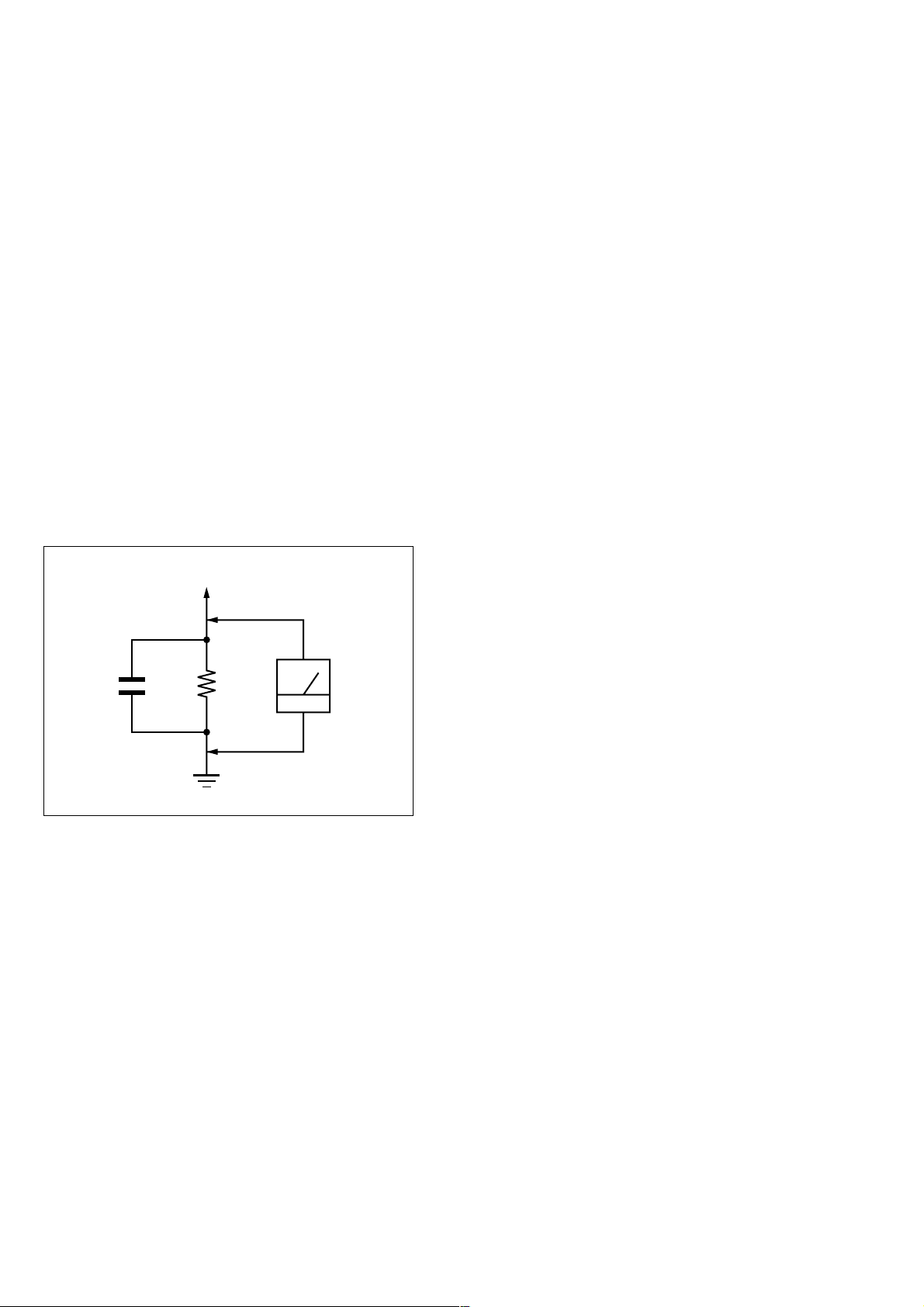
3. Measuring the voltage drop across a resistor by means of a
VOM or battery-operated AC voltmeter. The “limit” indica-
tion is 0.75V, so analog meters must have an accurate low-
voltage scale. The Simpson 250 and Sanwa SH-63Trd are ex-
amples of a passive VOM that is suitable. Nearly all battery
operated digital multimeters that have a 2V AC range are suit-
able. (See Fig. A)
AC
0.15 µF
1.5 k
Ω
Earth Ground
Voltmeter
(0.75 V)
Fig. A Using AC voltmeter to check AC leakage
SAFETY-RELATED COMPONENT WARNING!!
COMPONENTS IDENTIFIED BY MARK 0 OR DOTTED
LINE WITH MARK 0 ON THE SCHEMA TIC DIAGRAMS
AND IN THE PARTS LIST ARE CRITICAL TO SAFE
OPERATION. REPLACE THESE COMPONENTS WITH
SONY PARTS WHOSE PART NUMBERS APPEAR AS
SHOWN IN THIS MANUAL OR IN SUPPLEMENTS PUBLISHED BY SONY.
ATTENTION AU COMPOSANT AYANT RAPPORT
À LA SÉCURITÉ!
LES COMPOSANTS IDENTIFIÉS P AR UNE MARQUE 0
SUR LES DIAGRAMMES SCHÉMATIQUES ET LA LISTE
DES PIÈCES SONT CRITIQUES POUR LA SÉCURITÉ
DE FONCTIONNEMENT. NE REMPLACER CES COMPOSANTS QUE PAR DES PIÈCES SONY DONT LES
NUMÉROS SONT DONNÉS DANS CE MANUEL OU
DANS LES SUPPLÉMENTS PUBLIÉS PAR SONY.
– 2 –

TABLE OF CONTENTS
Section Title Page Section Title Page
SERVICE NOTE ...................................................................... 4
6. ADJUSTMENTS
1. GENERAL
Play Timer...................................................................... 1-1
Cassette Door Lock (Safety Lock) ................................ 1-1
Recording and Tape Speed Buttons ............................. 1-1
Connections .................................................................. 1-2
2. DISASSEMBLY
2-1. Upper Case Removal .................................................... 2-1
2-2. Front Panel Section Removal ....................................... 2-1
2-3. Rear Panel (M) Removal .............................................. 2-1
2-4. Mechanism Deck Removal ........................................... 2-1
2-5. MA-370 Board Removal................................................ 2-2
2-6. Internal Views ................................................................ 2-3
2-7. Circuit Boards Location ................................................. 2-4
3. BLOCK DIAGRAMS
3-1. Overall Block Diagram .................................................. 3-1
3-2. Video Block Diagram..................................................... 3-3
3-3. Servo/System Control Block Diagram .......................... 3-5
3-4. Audio Block Diagram..................................................... 3-7
3-5. Power Block Diagram.................................................... 3-9
4. PRINTED WIRING BOARDS AND
SCHEMATIC DIAGRAMS
6-1. Mechanical Adjustments ............................................... 6-1
6-2. Electrical Adjustments ................................................... 6-1
2-1. Pre-Adjustment Preparations........................................ 6-1
2-1-1. Instruments to be Used............................................ 6-1
2-1-2. Connection ............................................................... 6-1
2-1-3. Set-up of Adjustment ................................................ 6-1
2-1-4. Alignment Tapes....................................................... 6-1
2-1-5. Specified I/O Level and Impedance
input/output terminal ................................................ 6-1
2-1-6. Adjusting Sequence ................................................. 6-2
2-2. Power Supply Adjustment ............................................. 6-2
2-2-1. Power Supply Check................................................ 6-2
2-3. Servo System Adjustment............................................. 6-2
2-3-1. RF Switching Position Adjustment........................... 6-2
2-4. Audio System Adjustments ........................................... 6-3
2-4-1. Normal Audio System Adjustment ........................... 6-3
1. ACE Head Adjustment .................................................. 6-3
2. E-E Output Level Check ............................................... 6-3
3. Frequency Response Check......................................... 6-3
2-5. Parts Arrangement Diagram for Adjustments............... 6-4
7. REPAIR PARTS LIST
7-1. Exploded Views ............................................................. 7-1
7-1-1. Front Panel and Chassis Assembly ......................... 7-1
7-1-2. Mechanism Chassis Assembly (1) ........................... 7-2
7-1-3. Mechanism Chassis Assembly (2) ........................... 7-3
7-1-4. Mechanism Chassis Assembly (3) ........................... 7-4
7-2. Electrical Parts List........................................................ 7-5
4-1. Frame Schematic Diagram ........................................... 4-3
4-2. Printed Wiring Boards and Schematic Diagrams ......... 4-5
MA-370 Printed Wiring Board ....................................... 4-5
MA-370 (Head Amp) Schematic Diagram .................... 4-7
MA-370 (Video, Audio) Schematic Diagram................. 4-9
MA-370 (Servo/System Control)
Schematic Diagram ....................................................... 4-13
MA-370/QP-1 (Kids Sound) Printed Wiring Board
and Schematic Diagram................................................ 4-17
MA-370 (Mode Control) Schematic Diagram ............... 4-19
MA-370 (Power Supply) Schematic Diagram ............... 4-21
5. INTERFACE, IC PIN FUNCTION DESCRIPTION
5-1. System Control-Video/RP Block Interface
(MA-370 BOARD IC160)............................................... 5-1
5-2. System Control-Servo Peripheral Circuit Interface
(MA-370 BOARD IC160)............................................... 5-1
5-3. System Control-Mechanism Block Interface
(MA-370 BOARD IC160)............................................... 5-2
5-4. System Control-System Control Peripheral
Circuit Interface (MA-370 BOARD IC160) .................... 5-3
5-5. System Control-Audio Block Interface
(MA-370 BOARD IC160)............................................... 5-3
5-6. Servo/System Control Microprocessor Pin Function
(MA-370 BOARD IC160)............................................... 5-4
– 3 –

SERVICE NOTE
1. DISASSEMBLY
• This set can be disassembled in the order shown below.
Note: Pages in indicated pages in the SERVICE MANUAL.
Pages in indicated pages in the VHS MECHANICAL ADJUSTMENT MANUAL VI.
Set
Upper Case
(Page 2-1)
Front Panel
Section
(Page 2-1)
FL Complete
Ass’y
(Page 13)
Retainer
Plate
(Page 22)
FL Slider
Block Ass’y
(Page 22)
Cam Gear
(Page 23)
Pinch Press
Block Ass’y
(Page 14)
Mechanism
Deck
(Page 2-1)
Rubber
Belt
(Page 15)
Capstan
Motor
(Page 15)
Cam Motor
Retainer
(Page 31)
Ground Shaft
Ass’y
(Page 13)
Drum
Ass’y
(Page 13)
Rubber
Belt
(Page 15)
Pully Gear
Ass’y
(Page 29)
Reel Direct
Ass’y
(Page 30)
Rear Panel
(M)
(Page 2-1)
MA-370
Board
(Page 2-2)
Rotary
Switch
(Page 2-1)
Tuner
Unit
Rubber
Belt
(Page 15)
Slider
(Page 26)
Loading
Gear (T, S)
(Page 28)
Cam Motor
(Page 31)
– 4 –
SECTION 1
GENERAL
SLV-KS1
This section is extracted from instruction manual. (3-062-072-11)
Step Step
Step
Turn on your TV
D
O
O
R LO
CK
T
V
O
L
C
HV
TV/VIDEO
P
L
A
Y
F
F
ER
Insert your
tape here
PU
S
H
S
P/EP
RE
C
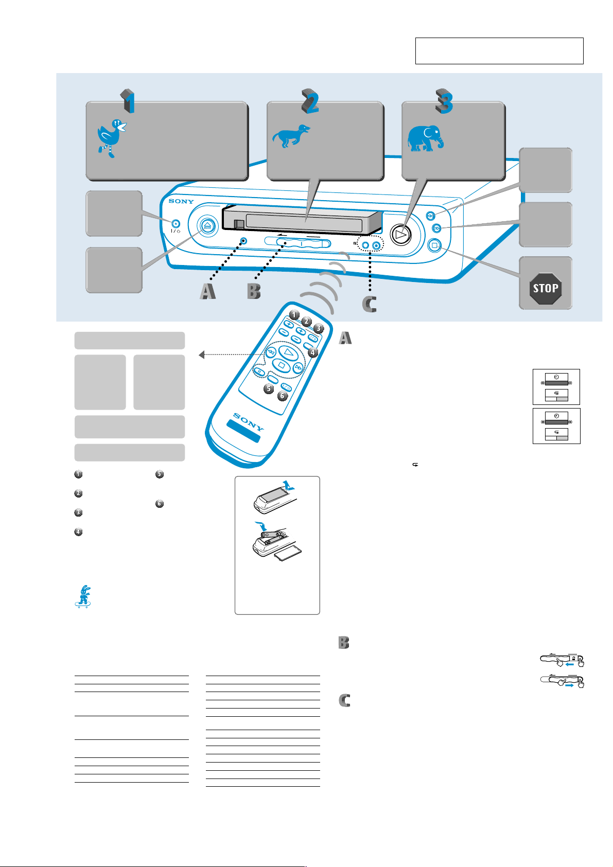
Play Timer
The Play Timer function allows you to control the amount of time your child watches a video. For
example, let’s say you want your child to watch a cartoon for 90 minutes.
Press the PLAY TIMER SET UP button for more than five seconds.
1
The set up screen appears on your TV.
Press the M (fast forward) or m (rewind) buttons to select 90
2
minutes.
The time will change in thirty minute increments. If you continue to
press either the M (fast forward) or m (rewind) button, the playing
time will scroll as follows:
OFF y 30 y 60 y 90 y 120 y 150 y 180 y OFF
After you select the playing time, press the PLAY TIMER SET UP button.
3
The ON/OFF row of the (repeat) option is highlighted.
Press the M (fast forward) or m (rewind) button to set the repeat function ON or OFF.
4
If you select ON and the tape reaches the end before the timer is up, it will automatically rewind
and play the tape from the beginning.
Press the PLAY TIMER SET UP button again.
5
The set up screen will disappear and the timer will start. Follow the steps above to start
watching a video.
When your child is watching a video, all of the buttons (except the z REC (record) button) will
work. After the set playing time has elapsed, the power will turn off and all of the buttons will be
locked for one hour. If you press a button while the VCR is locked, the light on the POWER I/1
button will flash for five seconds.
To check the remaining time
Press the PLAY TIMER SET UP button once. The remaining time will appear on your TV screen.
When five minutes are left, the remaining time will automatically appear on your TV screen for 30
seconds.
To cancel the Play Timer
Press the PLAY TIMER SET UP button for more than five seconds. When the set up screen appears
on your TV, use the M (fast forward) or m (rewind) buttons to set the timer to OFF.
Notes
• As soon as you complete step 5 above, the timer will start to run even if you turn off the VCR. This means that the VCR
may enter the lock mode while the power is off, or that when you turn the VCR back on, the Play Timer will return to
the last setting you made. Follow the explanations above to change or cancel the Play Timer.
• The repeat function will rewind the tape no more than five times, regardless of the tape length or timer setting.
Cassette Door Lock (Safety Lock)
You can lock the cassette door to prevent your child from inserting or ejecting
cassette tapes. To lock the door, press down the PUSH button and move the
DOOR LOCK slide to the left until it clicks in place.
To unlock the door, press down the PUSH button and move the DOOR LOCK
slide to the right.
Recording and Tape Speed Buttons
You can use this VCR to record images input through the LINE IN jacks. For example, let’s say you
want to record images of your child that you took with your video camera.
Press the SP/EP button to set the tape speed.
1
EP (Extended Play) provides recording time three times as long as SP (Standard Play).
However, SP produces better picture and audio quality.
Connect your video camera’s LINE OUT jacks to the LINE IN jacks on the back of this
2
VCR, and insert a blank tape with its safety tab intact into this VCR. (If you are recording
a program on your TV, be sure to disconnect the VCR’s LINE OUT jacks from your TV’s
LINE IN jack and set the TV’s TV/VIDEO button to TV.)
Press the z REC (record) button on this VCR.
3
Start playing the tape in your video camera.
4
The REC mark and tape speed (EP or SP) appear on your TV screen. To stop recording,
press x STOP.
Note
• The z REC button will not function when the Play Timer is activated. Cancel the Play Timer before you make a
recording.
and press your TV’s
TV/VIDEO* button
* The name of this button may be different
on your TV.
Press to
turn ON/
OFF
Press to
eject
N PLAY button
Press this button to play a tape.
m REW (rewind)
button
Press x STOP and
then this button to
rewind a tape. To
watch the picture in
fast motion, press this
button while the tape
is playing.
x STOP button
Press this button to stop the tape when it is
playing, rewinding, fast forwarding, or recording.
X PAUSE button
Press this button to momentarily stop the tape.
VOL +/– buttons:
These buttons change the
volume on your TV.
CH +/– buttons:
These buttons change the
channels on your TV.
TV I/1 (power) button:
Use this button to turn your TV
on and off.
TV/VIDEO button:
This button switches your TV
between regular TV programs
and the video input.
You must first program your remote
control to use the buttons 1 through
4 above (see below).
A playful animation will appear whenever you
rewind, fast forward, or insert a tape.
M FF (fast
forward) button
Press x STOP and
then this button to fast
forward a tape. To
watch the picture in
fast motion, press this
button while the tape
is playing.
Program your Remote Commander remote control!
You can set your remote control to control the power, channel, volume, and video input of your TV.
First find the manufacturer’s name of your TV. Then, while holding down the TV power button
(button TV I/1) on the remote control, press the operation buttons in the order shown in the chart.
Manufacturer
Sony
Akai/AOC/Emerson/Gold Star/
J.C.Penney/Marantz/MGA/
Mitsubishi/NEC/Philco/RCA/
War d s
Centurion/Curtis-Mathes/
Daytron/J.C.Penney/Magnavox/
MGA/Mitsubishi/NEC/Sampo/
Scott/Sylvania/Wards/York
Coronado/Emerson/Gold Star/
Hitachi/KMC/Magnavox/Philco/
Portland/Sharp/Teknika/Wards
Emerson/Radio Shack/Teknika
Fisher/Sanyo/Sears
General Electric/Panasonic/Quasar
POWER
DISPLAY button:
This button will turn on or off
the animations that appear
when you fast forward or
rewind a tape.
POWER /1 button:
Although this button turns the
VCR on and off, the VCR will
turn on automatically when
you insert a tape or press the
N PLAY, M FF, m REW,
z REC, or PLAY TIMER SET
UP buttons. The VCR will turn
off automatically if no buttons
are pressed for more than five
minutes after the tape is
stopped or ejected.
Press
N then x
N then X
M then x
N then m
m then N
M then N
x then m
PLA
Y TIM
ER
S
ET U
P
PAUSE DISPLA
V
ID
E
O
Inserting the batteries
Insert two size AA (R6) batteries by
matching the + and – on the batteries
to the diagram inside the battery
compartment.
Insert the negative (–) end first, then
push in and down until the positive
(+) end clicks into place.
Manufacturer
General Electric/RCA/Sears
Gold Star/MGA/Mitsubishi
Hitachi
JVC
Magnavox/Philips/Sylvania/
Teknika
Marantz/MGA/Mitsubishi
Panasonic
Pioneer
Quasar/Sharp
Radio Shack/Sharp
Sears/Toshiba
Zenith
REW
S
T
O
P
Y
m
POW
Press
M then X
X then N
N then M
M then m
x then N
m then X
X then M
m then M
X then x
x then M
x then X
m then x
Press to
play!
Press to
rewind
Press to
fast
forward
Press to
OFF
O N OFF
90MIN
O N OFF
PUSHDOOR LOCK
DOOR LOCK PUSH
1-1
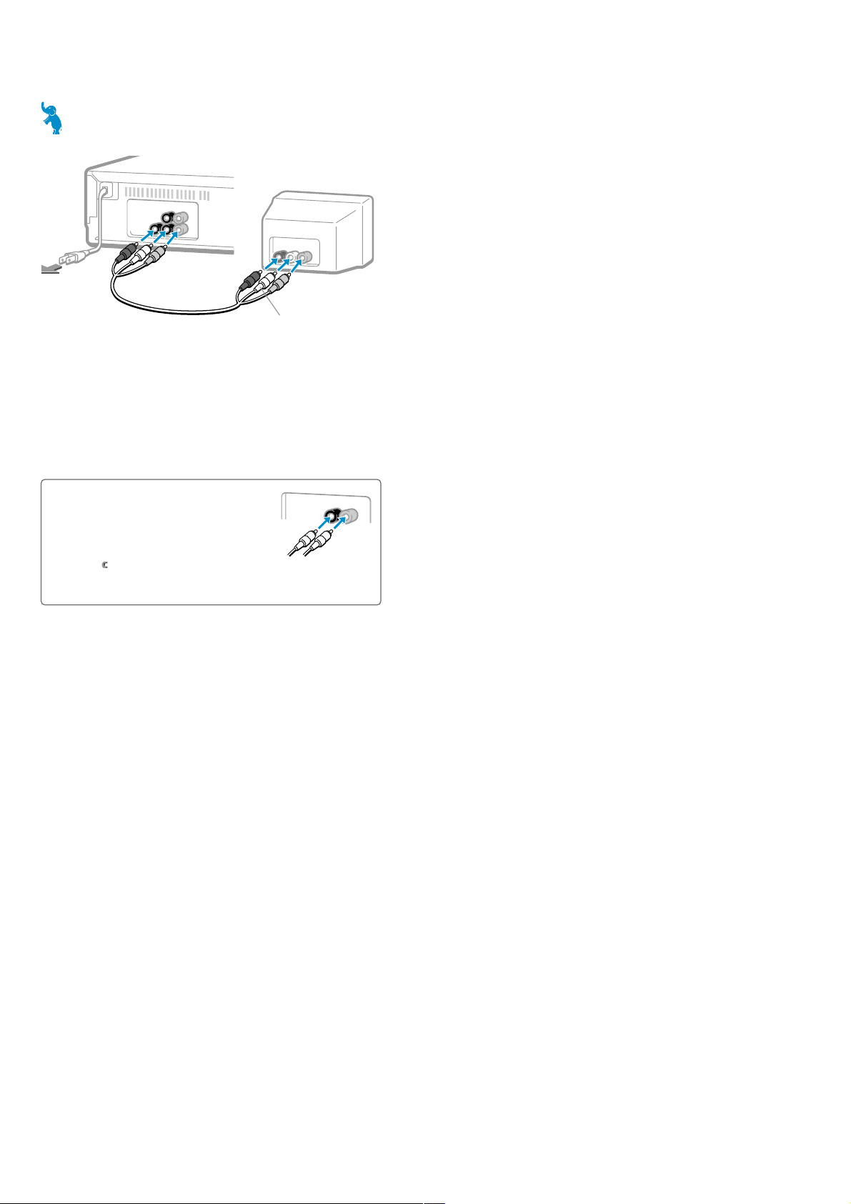
Connections
Follow the steps below to connect your TV to the VCR.
VCR
Your TV
A
U
D
IO
(M
O
N
O
)
V
ID
E
U
T
1
VIDEO OUT
O
AUDIO IN R
2
A
U
D
IO
V
ID
R
L
1
VIDEO IN
AUDIO IN L
E
O
L
IN
E
IN
L
IN
E
O
2
AUDIO
3
to an AC outlet
Step 1
Using the supplied audio/video cable, connect one of the yellow plugs to VIDEO of LINE OUT on
this VCR, and the other yellow plug to VIDEO of LINE IN on your TV.
Step 2
Connect both of the red and white plugs, in any order, to the black AUDIO LINE OUT jacks on this
VCR, and the other ends to the AUDIO LINE IN jacks on your TV. If your TV is monaural (only one
AUDIO LINE IN jack), you only need to use one of the red or white plugs. Just be sure to connect
the same color plug to both the VCR and your TV.
Step 3
Plug in the power cord to an AC outlet.
Note
• If your TV only has an RF jack (antenna jack), you need to use an RF modulator (not supplied) to connect this VCR.
OUT
Refer to your modulator’s instruction manual for further details.
Using the LINE IN jacks
When you want to use this VCR to make a recording, connect
LINE IN on this VCR to LINE OUT of your other video source
(such as a video camera, TV, or another video deck) using an
audio/video cable (not supplied). If your other video source
has a stereo LINE OUT (three jacks), use the audio/video
cable VMC-910MS (sold separately). Play the original tape on
the other video source and use this VCR to make the
recording. See “
Note
• If you connect your TV’s LINE OUT jacks to the LINE IN jacks, be sure to disconnect the VCR’s LINE OUT jacks
from your TV’s LINE IN jacks.
Recording and Tape Speed Buttons” on the reverse for more information.
AUDIO IN
LINE IN
AUDIO
(M
O
N
O
)
VIDEO IN
VIDEO
1-21-2 E
SECTION 2
DISASSEMBLY
Note: Follow the disassembly procedure in the numerical order given.
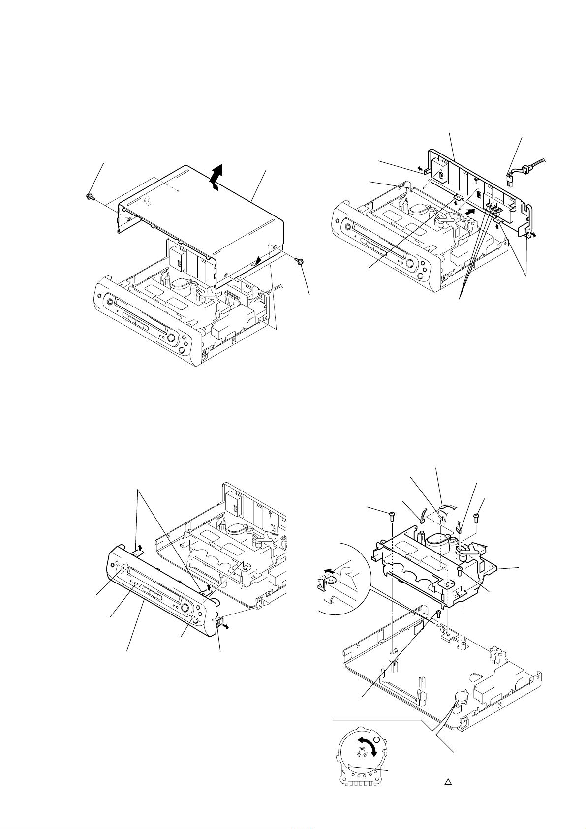
2-1. UPPER CASE REMOVAL 2-3. REAR PANEL (M) REMOVAL
SLV-KS1
1 Two tapping screws
3 Upper case
2 Two tapping
screws
4 Claw
2 Harness
3 Claw
7 Rear panel (M)
6 Three claws
1 Power cord
(CN600)
5 Two claws
2-2. FRONT PANEL SECTION REMOVAL
5 Two claws
2 Claw
1 Claw
3 Claw
6 Front panel section
4 Claw
2-4. MECHANISM DECK REMOVAL
3 Flat cable
7 Screw
(BVTP3 × 12)
6 Claw
2 Flexible board
(FFM-001)
1 Connector
(FE head)
5 Screw
(B3)
4 Connector
(ACE head)
8 Screw
(BVTP3 × 12)
0 Mechanism
deck
9 Screw
(BVTP3 × 12)
2-1
Note: When mounting the mechanism deck,
first align mark on the rotary switch.
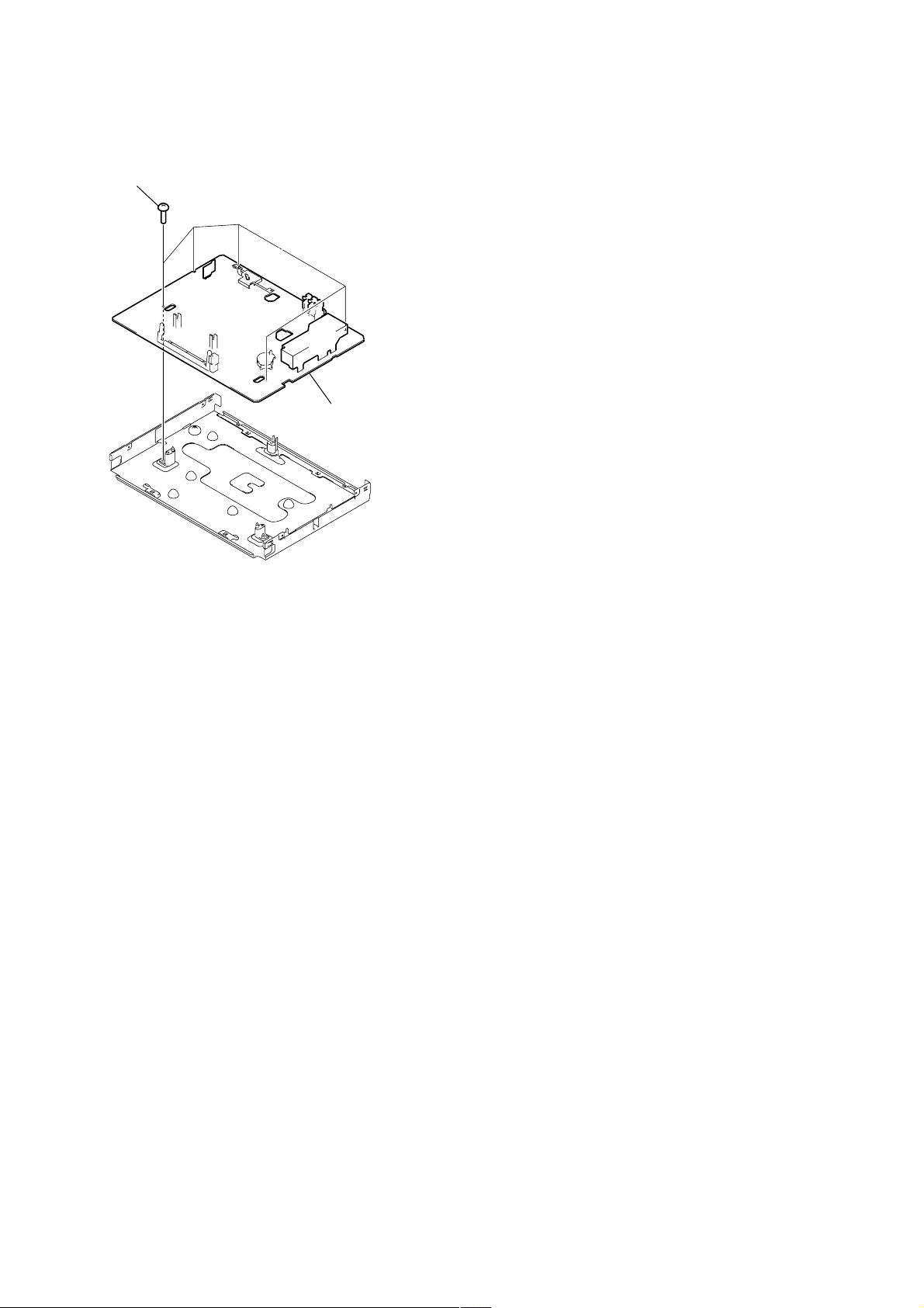
2-5. MA-370 BOARD REMOVAL
1 Five screws
(B3)
2 MA-370 board
2-2
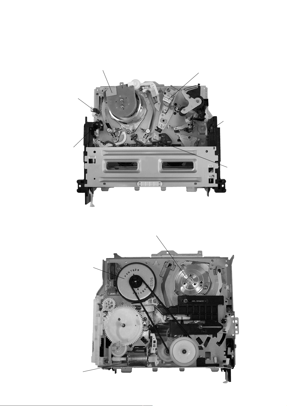
2-6. INTERNAL VIEWS
Drum assembly (M901) (DZH-0A2A/Z-RP)
8-839-049-53
FE head
1-500-144-11
Q002
Tape top sensor
8-729-043-84
ACE head block assembly
A-6759-620-A
Q001
Tape end sensor
8-729-043-84
D001
Tape top/end LED
8-719-048-26
M902
Capstan motor
1-698-971-11
M903
Cam motor assembly
X-3947-577-1
Drum assembly (M901) (DZH-0A2A/Z-RP)
8-839-049-53
2-3
2-7. CIRCUIT BOARDS LOCATION
QP-1
(KIDS SOUND)
MA-370
HEAD AMP, VIDEO, AUDIO, I/O,
SERVO/SYSTEM CONTROL,
()
POWER SUPPLY, MODE CONTROL
2-4
2-4 E
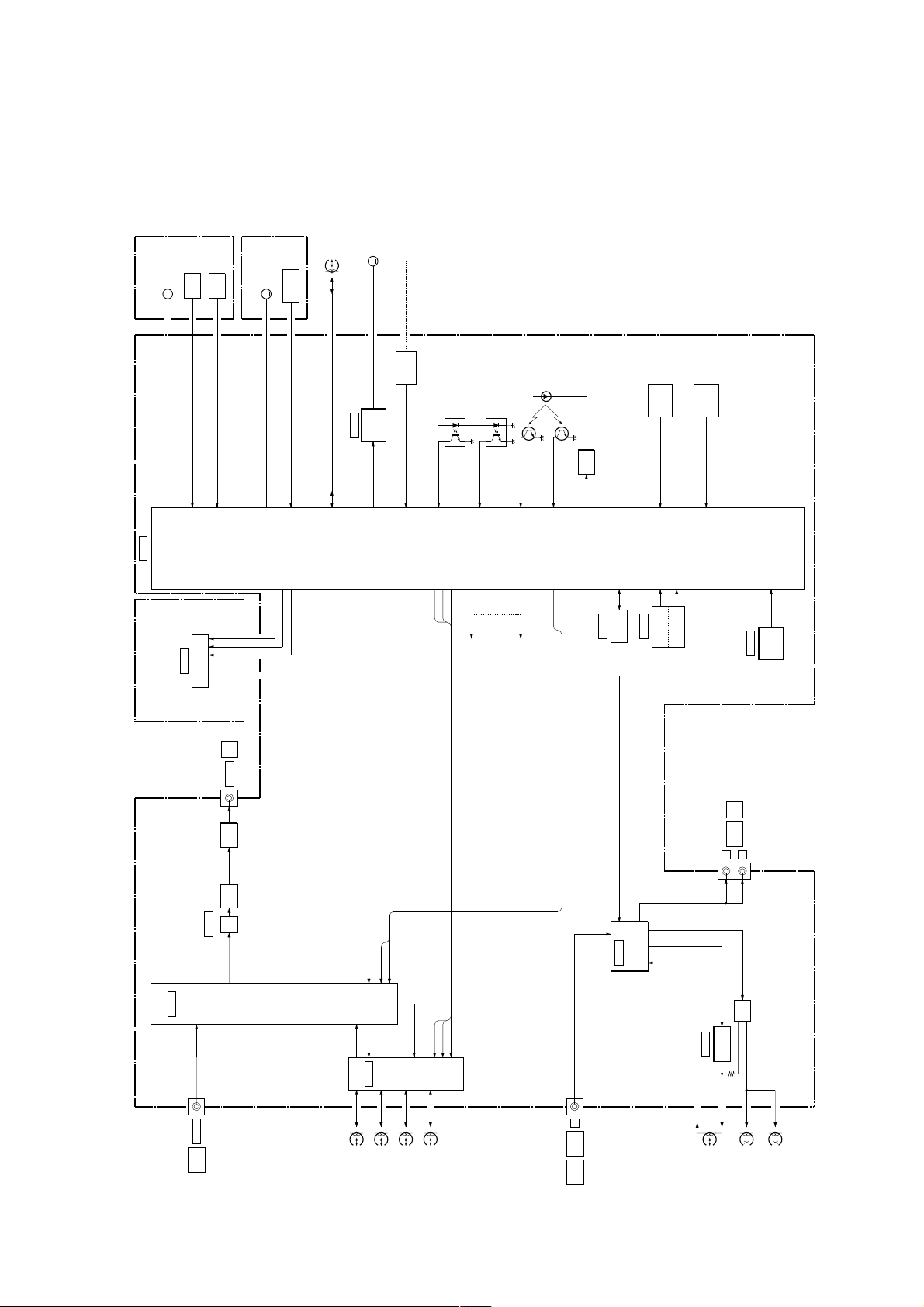
SLV-KS1
M901
DRUM
MOTOR
M
DRUM MOTOR
D VS
(2/2)
IC160
DRUMPGDRUM
D FG
D PG
FG
M902
MOTOR
CAPSTAN
FG
M
CAPSTAN
CAPSTAN MOTOR
CAP FG
CAP VS
CTL
HEAD
CTL REC/PB
IC101
M903
CAM
MOTOR
LOADING
M
DRIVE
MOTOR
CAM +,-
S102
CAM
ENCODER
MODE1-4
SERVO/
SYSTEM
CONTROL
SW12V
T REEL FG
PH102
(T. REEL)
S REEL FG
PH101
(S. REEL)
T SENS
Q101
(T. SENS)
D103
(T/S. LED)
Q102
S SENS
(S. SENS)
Q103
LED
DRIVE
T/S LED
KEY
FUNCTION
FUNC KEY 2
KEY
FUNCTION
FUNC KEY 1
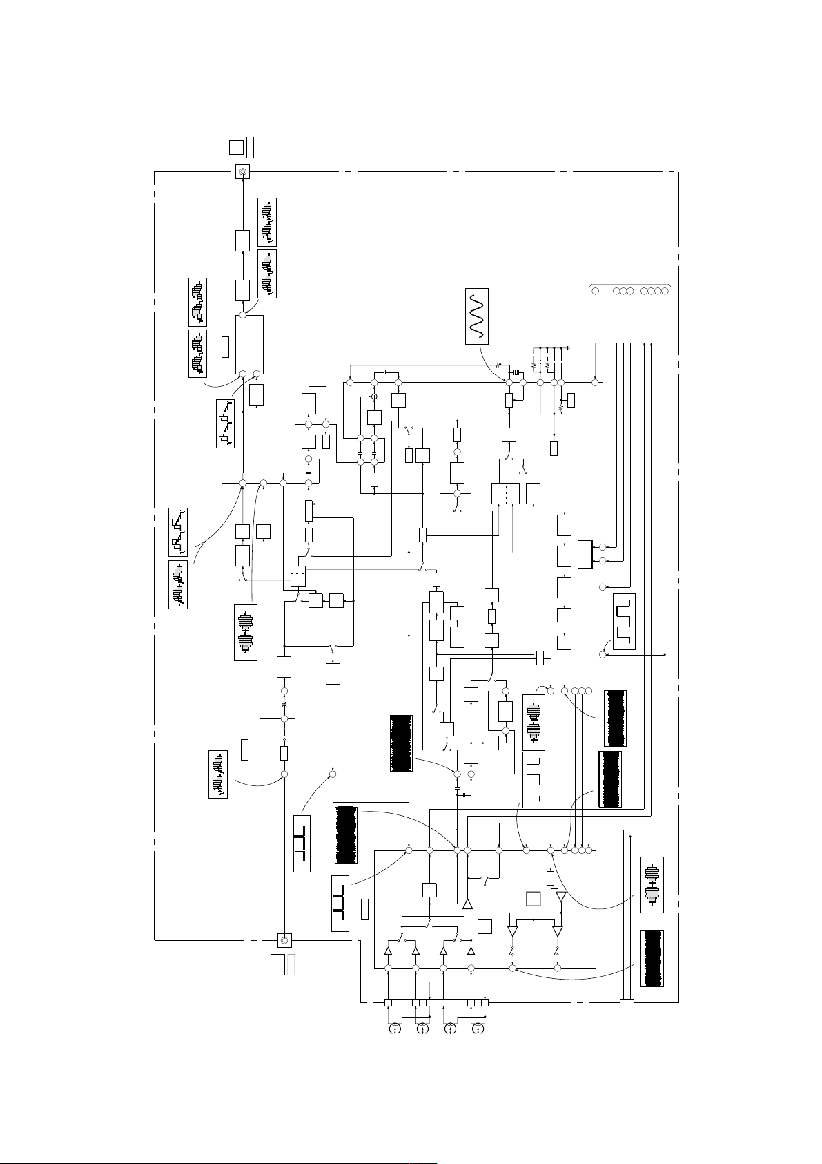
SECTION 3
BLOCK DIAGRAMS
(SEE PAGE 4-17)
IC999
QP-1 BOARD
MA-370 BOARD
(SEE PAGE 4-7,9,13,19,21)
(1/2)
IC201
KIDS SOUND
Y/C
CCD
PROCESS
IC160
DELAY
J562 (3/4)
Q561
Q500
(1/2)
LINE
OUT
VIDEO
BUFFER
RF VIDEO
BUFFER
OSD
AUDIO OUT
PLL CLOCK
PLL DATA
PLL ENB
PB Y/C
Q VD
Q VD
REC Y/C
I2C CLK
I2C DATA
C SYNC
HA SWP
HA SWP
RF ENV
RF SWP
RF ENV
RF SWP
SIGNAL
CONTROL
I2C CLK
I2C DATA
IC161
EEPROM
NORM OUT
(2/2)
IC201
AUDIO
NOMAL
IC162
PROCESS
POWER
FAIL DET
RESET
PULSE GEN
IC350
J562 (4/4)
HEAD
LINE
AUDIO
L
T380,Q380
SWITCH
OUT
(MONO)
R
BIAS
REMOCON
IC403
REMOTE
CONTROL
RECEIVER
3-1 3-2
OCS
3-1. OVERALL BLOCK DIAGRAM
L VIDEO 1
VIDEO
LINE
J562 (1/4)
AMP
VIDEO
IC260
REC/PB
DRUM
SP
IN
CH 1SPCH 2EPCH 1EPCH 2
L 1(L)
AUDIO
LINE
J562 (2/4)
L
(MONO)
IN
A HEAD PB
REC/
AUDIO
A HEAD REC
PB
HEAD
AUDIO
ERASE
HEAD
FULL
ERASE
05
HEAD
LINE
OUT
VIDEO
J562 (2/4)
PB
(H)
2.3Vp-p
IC160 ts
Q561
BUFFER
(H)
REC
2.2Vp-p
IC160 ts
Q500
(H)
BUFFER
2.3Vp-p
IC160 t; PB
IC160 t; REC
(H)
IC201 wl PB
2.3Vp-p
(H)
2.1Vp-p
IC201 wl REC
52
(1/3)
OSD V OUT
(H)
OSD
IC160
2.2Vp-p
REC/PB
IC160 th
IC201 ej REC
C VIDEO IN
OSD V IN
50
56
Q502
BUFFER
Q203
24
VIDEO
BUFFER
41
1H
DL
CLP
43 46 47
YNR
RP
LPF
P
R
FBC 1/2
Y/C
MIX
P
R
R
AGC
SYNC
(H)
2.0Vp-p
29
23
KIL
6dB
B.D
AMP
INS
CHARA
P
R
(H)
0.5Vp-p
IC201 wd PB
3237 31
(1/2)
CLP
IC201
CCD DELAY
Y/C PROCESS
(H)
1.0Vp-p
PIC
P
SEP
28
50
CCD_CLOCK_IN
CONT
5259
63
AMP
DL
1H/2H
55
5361
DL
EQ
LPF
INV
Q202
BPF1
P
R
BPF2
MAIN
COMV.
AMP
BACK UP
ACC
AMP
P
R
C
(V)
0.6Vp-p
IC201 1 PB
R
(3.579545MHz)
IC201 yj REC/PB
460mVp-p
X201
3.579545MHz
67
66
656260
VXO1
CLP
DE
EMPH
10 17
P
R
SUB
BPF
SUB
COMV.
REC
APC
B
PA
P
R
PB
PB
BGA-B
BGA-A
LPF
SUB
DEM
FM
AGC
SLD
VCO
REC
BGA
ENH
DETAIL
N.L
SERIAL
EMPH.
DECODER
MAIN
EMPH.
FM
MOD
EQ
REC
KIL
IC201 2 REC
IC260 4 REC/PB
REC_C OUT
2
(H)
380mVp-p
(V)
3.6Vp-p
REC_FM_OUT
REC_H_OUT
7
95
TRICK_H_OUT
REC _CURRENT_CTL
16
99
S
N
EQ
SQPB
Q201
BUFFER
LPF
P
1
6 8
PB
EQ
FM
AGC
4
72
13
Q VD IC160
25
QV/QH_INS
2021
96
C ROT PULSE IN
REC/PB
IC201 ok
98
RF_PULSE_IN
IC201 7 REC
IC260 9 REC
SYSCON
FROM/TO
C ROT IC160 15
I2C CLK IC16071I2C DATA IC160
360mVp-p
170mVp-p
BLOCK
(SEE PAGE 3-5)
17
RF ENV IC160 8
ENV SW IC160
(30Hz)
1.6Vp-p
18
HA SWP IC16016RF SWP IC160
SLV-KS1
3-2. VIDEO BLOCK DIAGRAM
(SEE PAGE 4-7,9,13)
MA-370 BOARD (1/3)
J562 (1/4)
IC260 5 REC/PB
(V)
0.6Vp-p
IC260 7 PB
5
H_SYNC
(H)
3.5Vp-p
IC260
VIDEO REC/PB AMP
PB
PB
16
19
CN260
879
6
DRUM
SP
CH1SPCH2EPCH1EPCH2
6
ENVDET_OUT
ENV
DET
PB
7
2
3
PB_OUT
COMP_OUT
HA (EP/SP)
COMP
HA
CONT
REC
PB
24
21
11
17
10
4
SW30
9
1
10
12
11
REC_C_IN
DET
AGC
ATF
REC_Y_IN
AGC
REC/MUTE/PB
TRICK. H
REC_CURRENT_ADJ2
(H)
380mVp-p
IC260 0 REC
3-3 3-4
REC
3.8Vp-p
CN270
PB RF
2
CHECK
RF SWP
3
PIN
IC260 qj REC
05
22
(H)
4.2Vp-p
IC201 wk REC/PB
IN
LINE
VIDEO
SLV-KS1
QP-1 BOARD (1/2)
(SEE PAGE 4-17)
FOR
CHECK
4
3
2
CN104
S-CLK
RESET
S-DATA
IC161
DATA
EEPROM
5
32I2C DATA EEP
(3/3)
IC160IC160
SYSTEM CONTROL
(1/2)
IC999
KIDS SOUND
CN999
CLK
6
31I2C CLK EEP
(1/2)
PLL DATA
X999
7
XT
STPIPDWN
128
312
PLL CLOCK
59
60
PLL CLK
PLL DATA
RST
34
4MHz
6
XT
PLL ENABLE
61
PLL ENABLE
P FAIL
78
D401
POWER LED
LED
Q405
DRIVE
83
MAIN/SAP
T REEL 80
REC/PB
IC999 6
S REEL
79
(4MHz)
3.0Vp-p
T SENS
7
S SENS
6
END LED
20
REC PRF
30
4fsc (in)
38
4fsc (out)
39
z
REC
S424
S425
SETUP
PLAY TIMER
S423
EP/SP
OSC IN
44
OSC OUT
45
S406
S412
S401
5FUNC KEY1
EJECT
STOP
POWER
IC403
REMOTE
CONTROL
RECEIVER
1
A
B
S409
PLAY
x
M
FF
S413
1
M
REW
S410
4FUNC KEY2
14REMOCON
MODE1
MODE2
MODE3
MODE4
CAM
33
292827
QVD
ENV SW
C ROT
V RF ENV
HA SWP16RF SWP18I2C DATA72I2C CLK
26
8
13
17
15
A MUTE
71
63A MUTE
(2/3)
(SEE PAGE 4-13)
IC160
SERVO CONTROL
D109
M12V
MA-370 BOARD (2/3)
CN101
1
1
VCC
OUTPUT
IC162
D VS
RESET
DRUM ERR
77
2
2
6
GEN
PULSE
PG REC/PB
IC160 o;
OUTPUT
M
8
FAIL
POWER
IC160 i;T REEL
DET
MATRIX
HALL
(30Hz)
4.6Vp-p
DEVICE
PH102
(T. REEL)
SW12V
1.6sec (TAPE TOP)
4.8Vp-p
DRUM PG90DRUM FG
D PG
3
3
PG
M901
PH101
(S. REEL)
IC160 ul S REEL
89
SW5VM12V
M12V
D FG
4
4
FG
SW5V
DRUM MOTOR
PS101
CN102
Q101
0.9sec (TAPE TOP)
4.8Vp-p
LIMITER
1
7
1
7
VM
VCC
U+
U-V+V-W+W-
(T. SENS)
D5V
FG REC/PB
IC160 il
6
6
TL
HALL
DEVICE
L500
REC
PROOF
REC/PB
IC160 el
C160 ij CAP FG SP
FG
MOTOR
CAPSTAN
(1078Hz)
4.4Vp-p
CN161
X160
CTL(X)
14.31818MHz
(14.31818MHz)
5.0Vp-p
CTL (Y)
1
CTL
HEAD
REC/PB
(25.3MHz)
4.6Vp-p
IC160 rg
4
IN 2
CAM
IC101
CAM (+)
CAM (-)
MOTOR DRIVE
2
M903
(30Hz)
5.0Vp-p
CN103
MOTOR
LOADING
10
S102
CAM
ENCODER
132
M
94
IC160 og REC
3
Q VD
25
IC201
RF ENV
6
IC260
ENV SW
2
IC260
,IC260
VIDEO
TO/FROM
RF SWP
HA SWP
3
4
,IC260
98
IC201
BLOCK
(SEE PAGE 3-4)
C ROT
96
IC201
I2C CLK
I2C DATA
20
21
IC201
IC201
TO
AUDIO
94
IC201
BLOCK
(SEE PAGE 3-10)
3-5 3-6
05
LED
Q103
DRIVE
Q102
(S. SENS)
S101
D103
D103
T/S. LED
CAP RVS24AMP Vref OUT91CAP FG87CTL + IN 95CTL - IN
CAP ERR
76
(360Hz)
4.5Vp-p
CAP VS
CTL-REF
CAP RVS
CAP FG
5
2
3
523
44
REF
U
V
W
CAPSTAN
M902
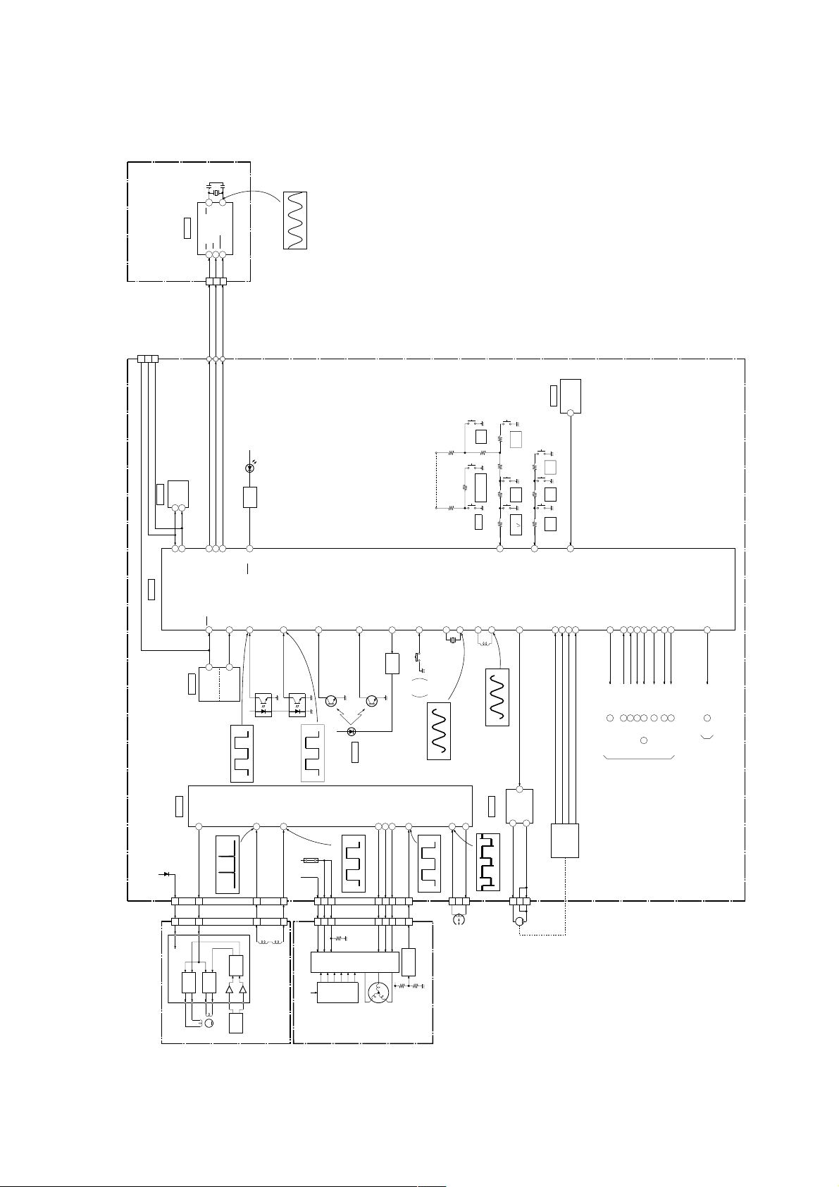
3-3. SERVO/SYSTEM CONTROL BLOCK DIAGRAM

LINE
J562 (4/4)
AUDIO
OUT
(MONO)
(SEE PAGE 4-9)
Q351
MUTE
SWITCH
(2/2)
IC201
AUDIO
NOMAL
EQ
PROCESS
REC
FROM
BLOCK
(SEE PAGE 3-5)
SYSCON
63
A MUTE IC160
80
81
82
94
REC
MUTE
LINE
AMP
P
R
93 92
ALC
L1
TU
89
74
78
REC
VREF
HA_PULSE_IN
97
AUDIO_MUTE_CTL
8487
85
PB:EP
REC:EP,LP
BIAS
AUTO
AUTO
86
88
(2/2)
AOUT
IC999
4
KIDS SOUND
(2/2)
(SEE PAGE 4-17)
QP-1 BOARD (2/2)
CN999
6
AUDIO OUT
SLV-KS1
3-4. AUDIO BLOCK DIAGRAM
MA-370 BOARD (3/3)
AUDIO
LINE
J562 (3/4)
(MONO)
IN
CN350
4
IC350
AUDIO
HEAD
REC/PB
42
HEAD
SWITCH
3
AUDIO
1
HEAD
ERASE
BIAS
Q350
SWITCH
OSC
BIAS
T380,Q380
FULL
ERASE
50Vp-p (69.9kHz)
T380 6 REC
CN351
1
HEAD
HEAD
05
3-7 3-8
 Loading...