

Sony RMT-V259D, SLV-SF90, RMT-V259F, RMT-V259G, RMT-V259H Service Manual
...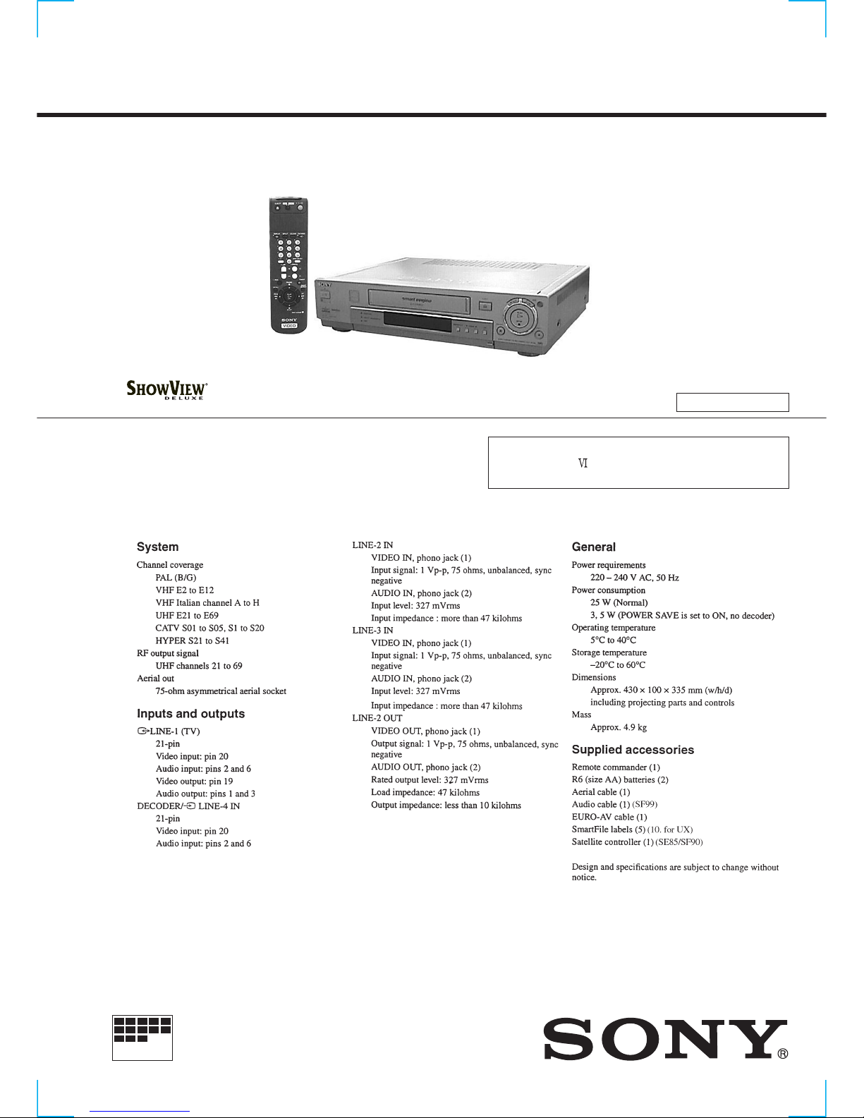
SLV-SE85/SF90/SF99
RMT-V259D/V259E/V259F/V259G/V259H/V259J/V260/V260A/V260B
SERVICE MANUAL
VIDEO CASSETTE RECORDER
MICROFILM
SR MECHANISM
SPECIFICATIONS
G
j
Refer to the SERVICE MANU AL of VHS MECHANICAL
ADJUSTMENT
for MECHANICAL ADJUSTMENTS
(9-921-647-13).
UK Model
SLV-SE85UX/SF90UX(SF)/
SF90UX(WF)/SF99UX
French Model
SLV-SE85B/SF90B(SF)/
SF90B(WF)/SF99B
German Model
SLV-SE85VC/SF90VC(SF)/
SF90VC(WF)/SF99VC
Spanish Model
SLV-SE85NP/SF90NP(SF)/
SF90NP(WF)/SF99NP
E Model
SLV-SF99EN
Irish Model
SLV-SF90EX
Photo: SL V-SF90
RMT-V259F

— 2 —
1. Check the area of your repair for unsoldered or poorly-soldered
connections. Check the entire board surface for solder splashes
and bridges.
2. Check the interboard wiring to ensure that no wires are
"pinched" or contact high-wattage resistors.
3. Look for unauthorized replacement parts, particularly
transistors, that were installed during a previous repair . Point
them out to the customer and recommend their replacement.
4. Look for parts which, through functioning, show obvious signs
of deterioration. Point them out to the customer and
recommend their replacement.
5. Check the B+ voltage to see it is at the values specified.
6. Flexible Circuit Board Repairing
• Keep the temperature of the soldering iron around 270˚C
during repairing.
• Do not touch the soldering iron on the same conductor of the
circuit board (within 3 times).
• Be careful not to apply force on the conductor when soldering
or unsoldering.
SAFETY CHECK-OUT
After correcting the original service problem, perform the following
safety checks before releasing the set to the customer.
SAFETY-RELATED COMPONENT WARNING!!
COMPONENTS IDENTIFIED BY MARK ! OR DO TTED LINE WITH
MARK ! ON THE SCHEMATIC DIAGRAMS AND IN THE PARTS
LIST ARE CRITICAL TO SAFE OPERATION. REPLACE THESE
COMPONENTS WITH SONY PARTS WHOSE PART NUMBERS
APPEAR AS SHOWN IN THIS MANUAL OR IN SUPPLEMENTS
PUBLISHED BY SONY .
ATTENTION AU COMPOSANT AYANT RAPPORT
À LA SÉCURITÉ!
LES COMPOSANTS IDENTIFÉS P AR UNE MARQUE ! SUR LES
DIAGRAMMES SCHÉMA TIQUES ET LA LISTE DES PIÈCES SONT
CRITIQUES POUR LA SÉCURITÉ DE FONCTIONNEMENT. NE
REMPLACER CES COMPOSANTS QUE PAR DES PIÈSES SONY
DONT LES NUMÉROS SONT DONNÉS DANS CE MANUEL OU
DANS LES SUPPÉMENTS PUBLIÉS PAR SONY.

— 3 —
TABLE OF CONTENTS
SERVICE MODE
1. ERROR CODE INDICATION··········································· 5
1. GENERAL
Getting Started
Step 1 Unpacking···································································1-1
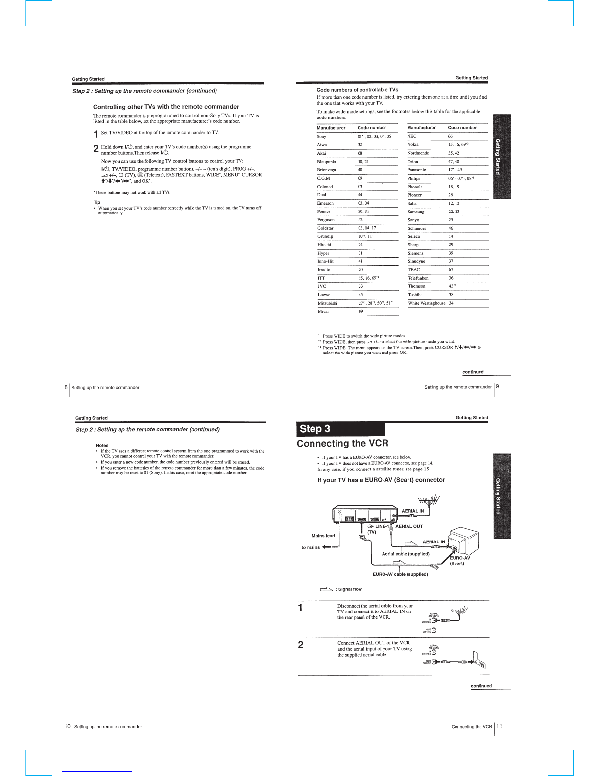
Step 2 Setting Up the remote commander ····························· 1-1
Step 3 Connecting the VCR···················································1-3
Step 4 Tuning your TV to the VCR ·······································1-4
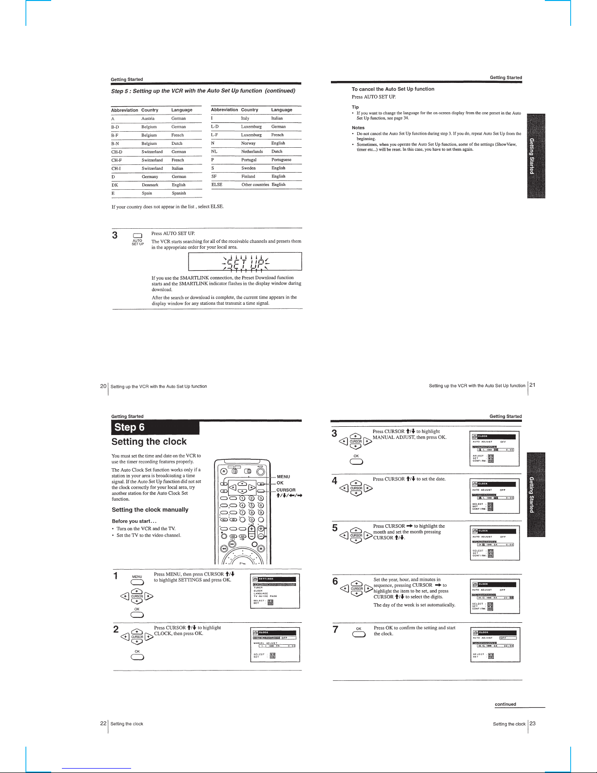
Step 5 Setting up the VCR with the Auto Set Up function ····1-4
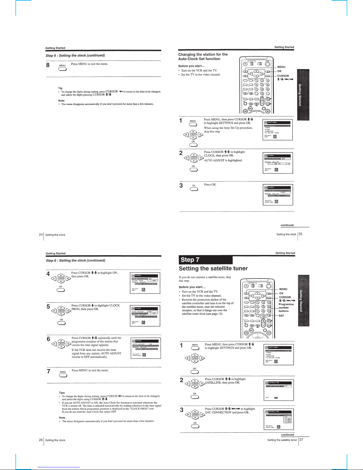
Step 6 Setting the clock ·························································1-5
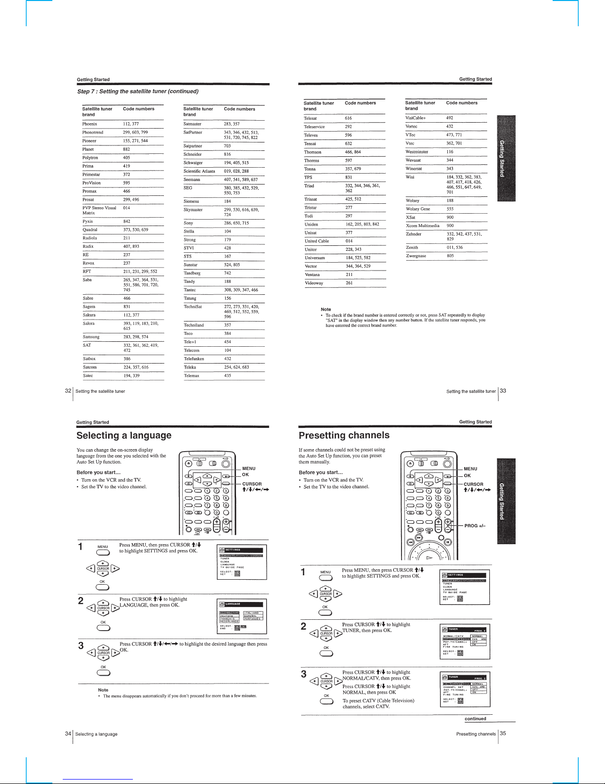
Step 7 Setting the satellite tuner ············································1-6
Selecting a language ······························································1-8
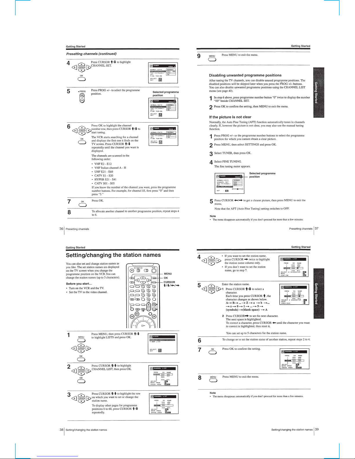
Presetting channels ································································1-8
Setting/changing the station names ·······································1-9
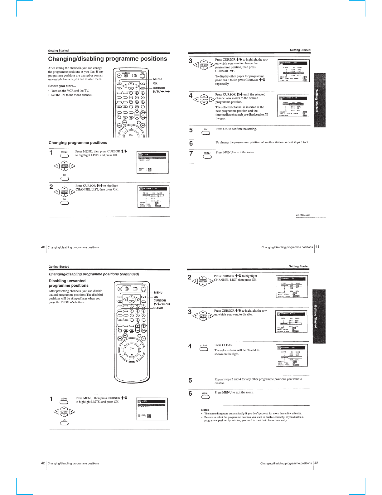
Changing/disabling programme positions ··························· 1-10
Setting the PAY-TV/Canal Plus decoder······························ 1-11
Basic Operations
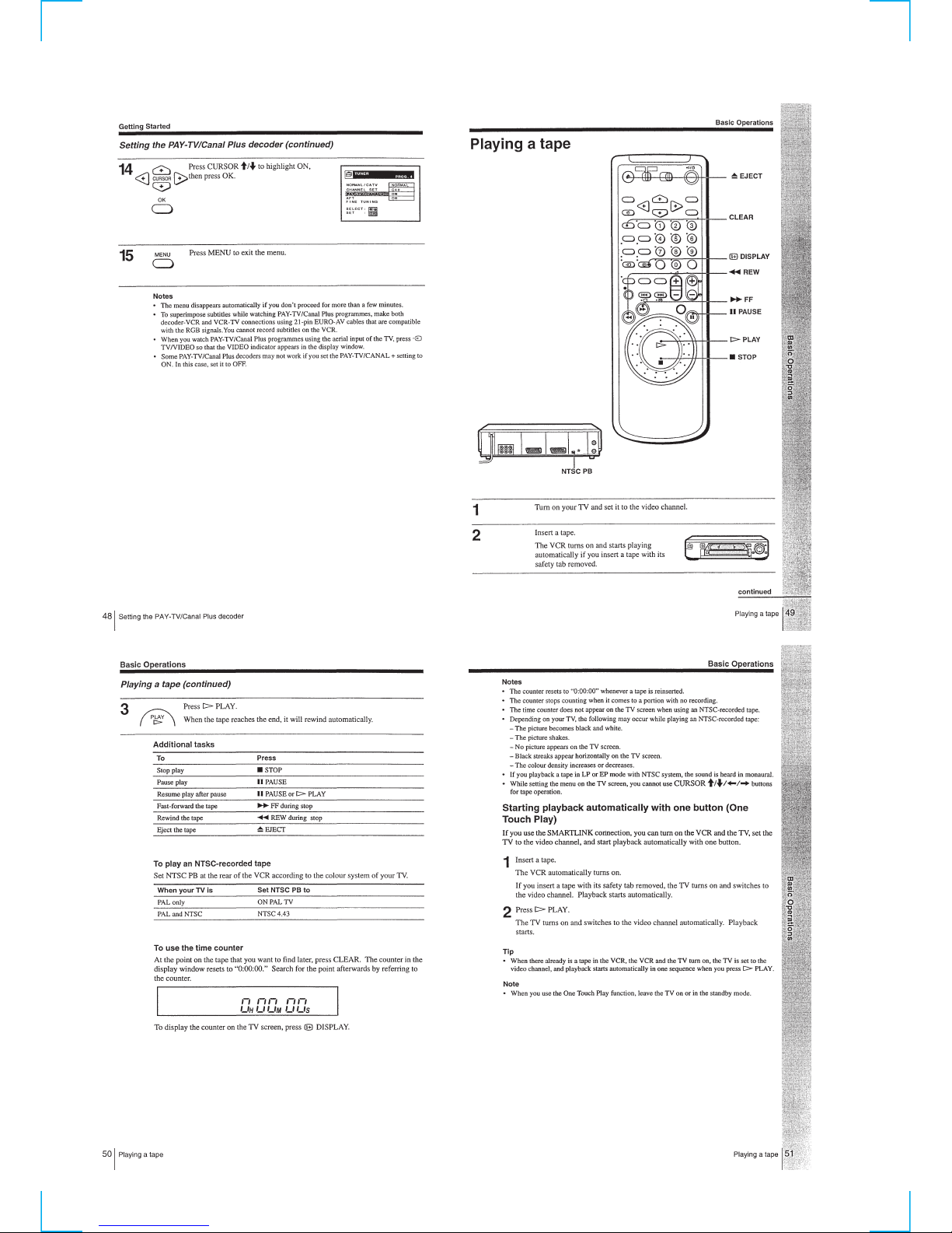
Playing a tape·······································································1-12
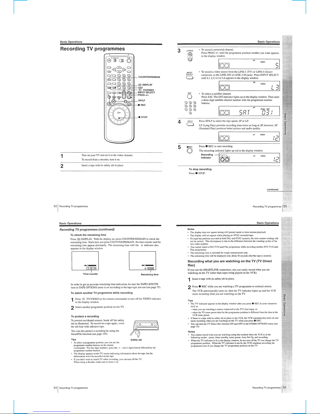
Recording TV programmes ·················································1-13
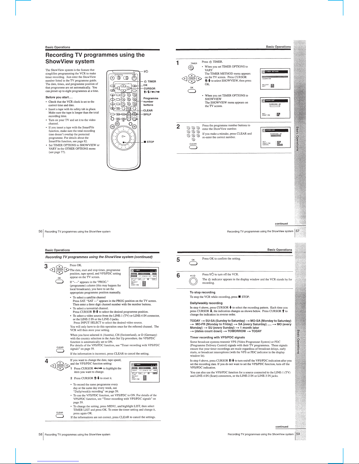
Recording TV programmes using the ShowView system ···1-14
Additional Operations
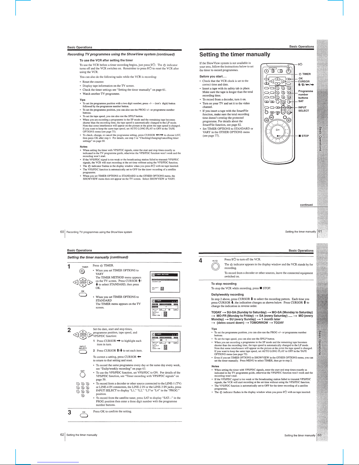
Setting the timer manually··················································· 1-15
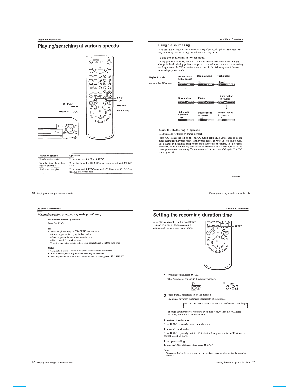
Playing/searching at various speeds ····································1-16
Setting the recording duration time ·····································1-16
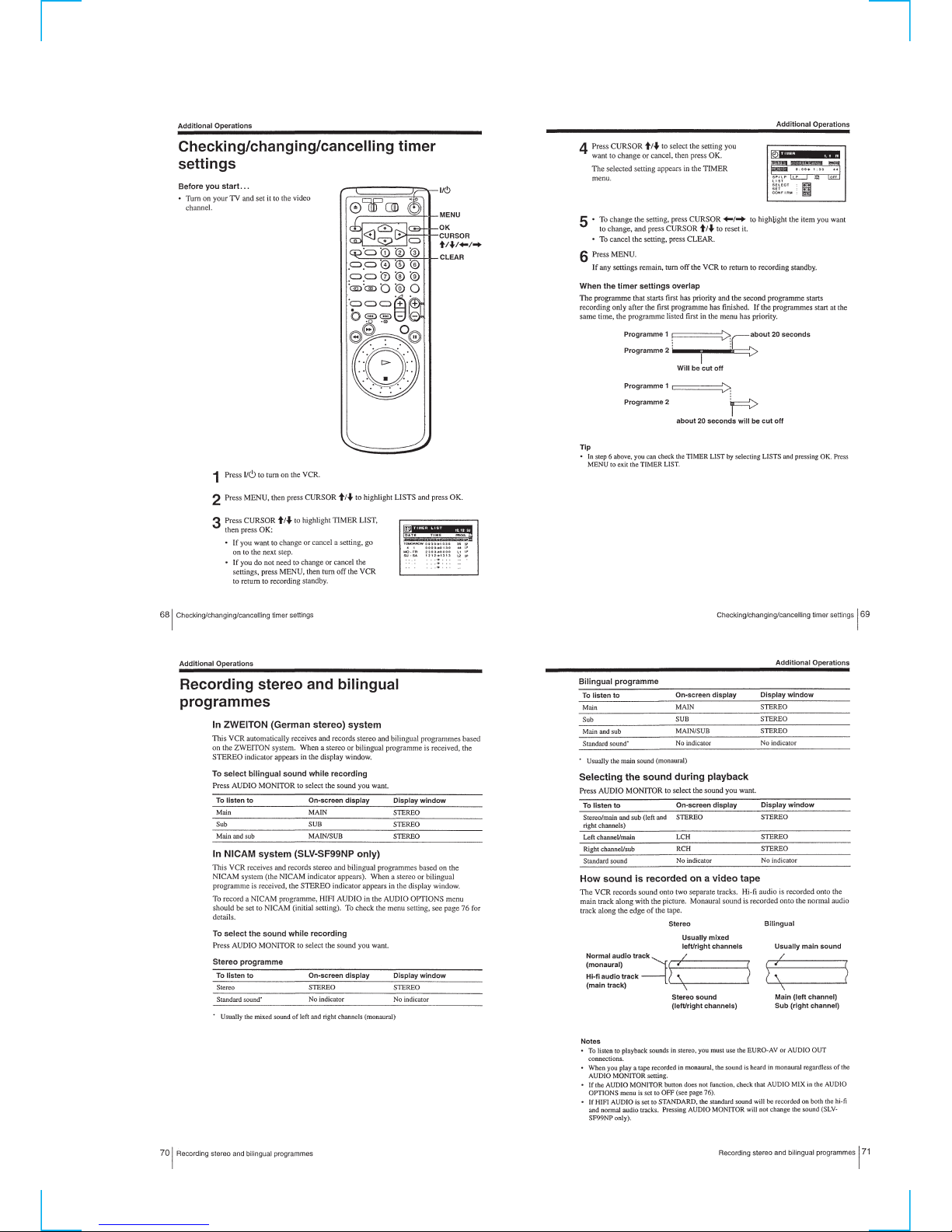
Checking/changing/cancelling timer settings ······················1-17
Recording stereo and bilingual programmes ······················· 1-17
Searching using the index function······································1-18
Adjusting the picture ···························································1-18
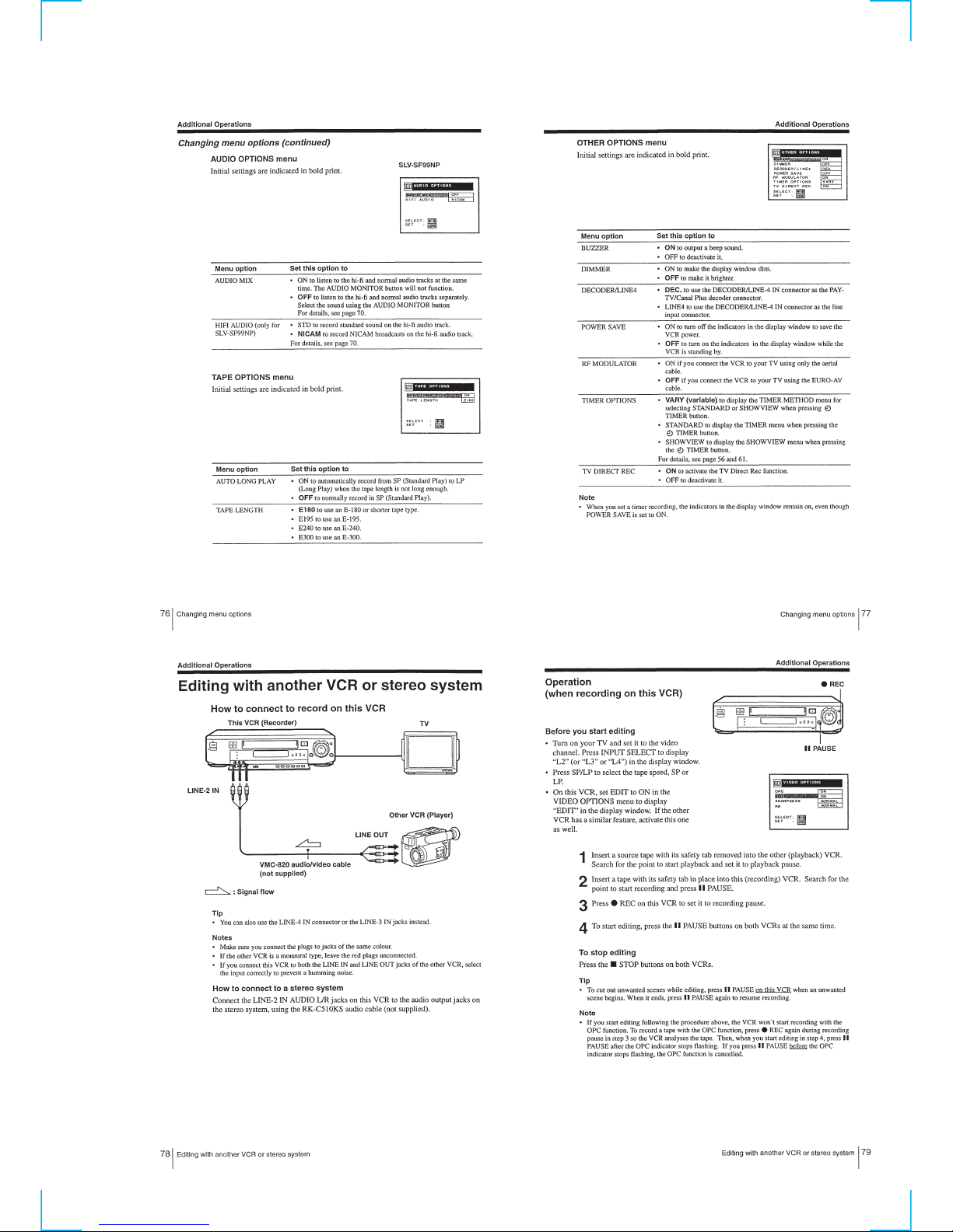
Changing menu options ······················································· 1-18
Editing with another VCR or stereo system ························1-19
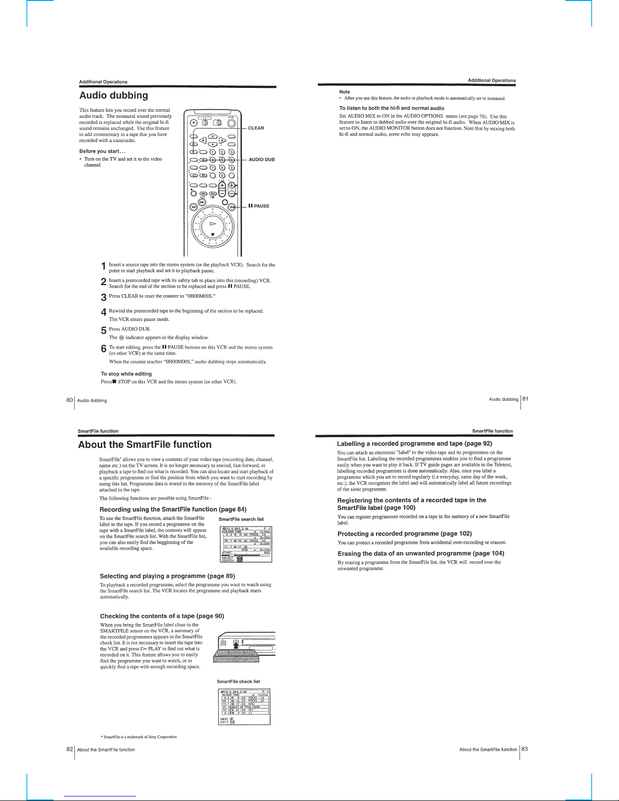
Audio dubbing ·····································································1-20
SmartFile function
About the SmartFile function ··············································1-20
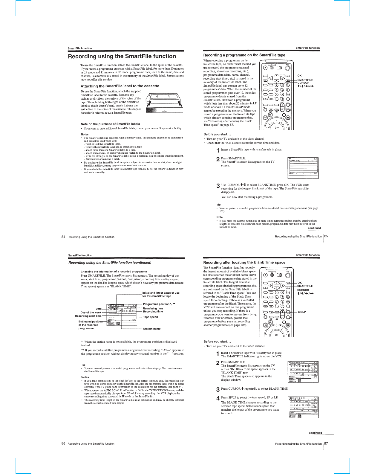
Recording using the SmartFile function ······························1-21
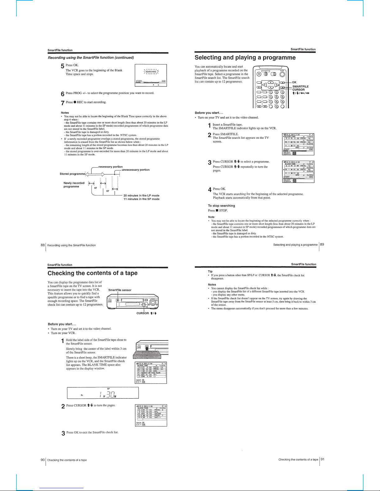
Selecting and playing a programme ····································1-22
Checking the contents of a tape ···········································1-22
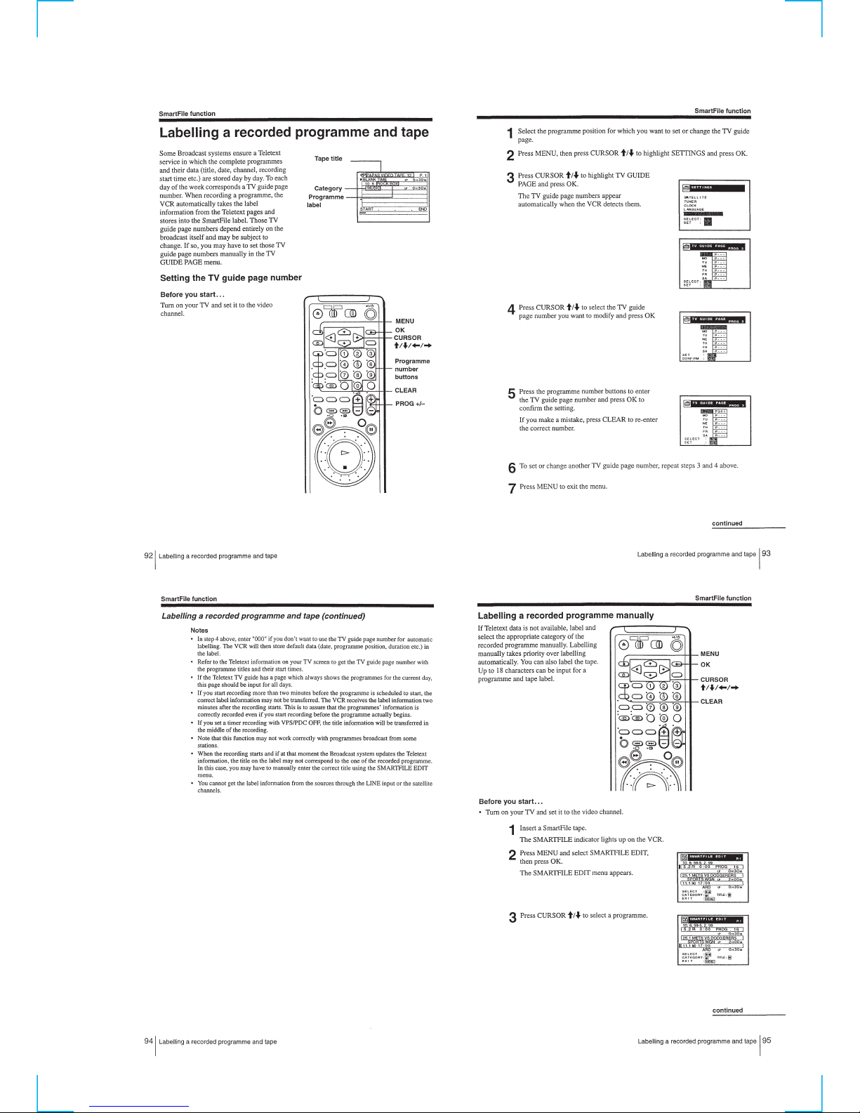
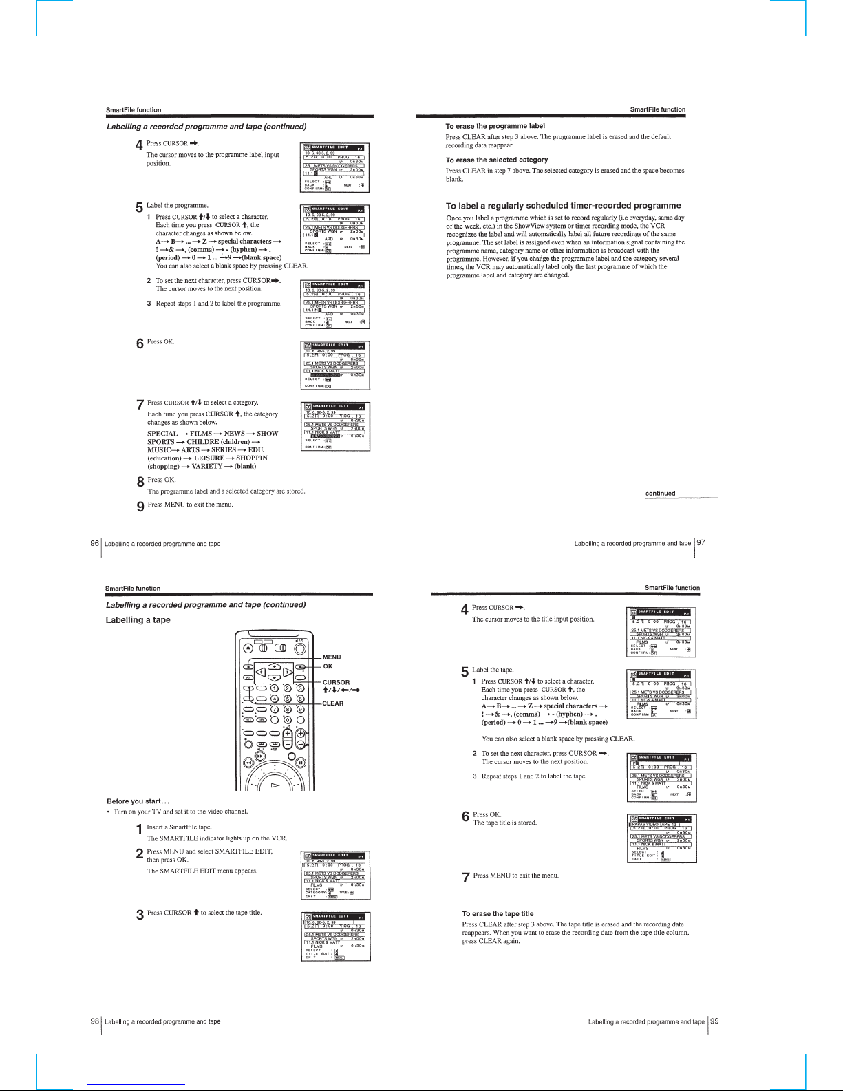
Labelling a recorded programme and tape ··························1-23
Registering the contents of a recorded tape in the
SmartFile label·····································································1-24
Protecting a recorded programme········································ 1-25
Erasing the data of an unwanted programme ······················1-26
Additional Information
Troubleshooting ···································································1-26
Index to parts and controls··················································· 1-28
Menu chart ···········································································1-29
2. DISASSEMBLY
2-1. CASE, FRONT PANEL BLOCK ASSEMBLY ··············2-1
2-2. DM-86, FR-161, JK-171, AT-26 BOARDS ····················2-1
2-3. REAR PANEL ·································································2-2
2-4. NR-27, RP-235 BOARDS···············································2-2
2-5. SR MECHANISM DECK···············································2-3
2-6. POWER BLOCK, MA-359 BOARDS····························2-3
2-7. INTERNAL VIEWS························································2-4
2-8. CIRCUIT BOARDS LOCATION ···································2-5
3 BLOCK DIAGRAMS
3-1. OVERALL BLOCK DIAGRAM (1) ······························3-3
OVERALL BLOCK DIAGRAM (2) ······························3-5
3-2. VIDEO BLOCK DIAGRAM (1) ····································3-8
VIDEO BLOCK DIAGRAM (2) ····································3-9
3-3. SERVO BLOCK DIAGRAM (1) ·································· 3-11
SERVO BLOCK DIAGRAM (2) ·································· 3-13
3-4. MEMORY BLOCK DIAGRAM···································3-15
3-5. AUDIO BLOCK DIAGRAM ········································3-17
3-6. POWER BLOCK DIAGRAM (1)································· 3-19
POWER BLOCK DIAGRAM (2)································· 3-21
4. PRINTED WIRING BOARDS AND
SCHEMATIC DIAGRAMS
4-1. FRAME SCHEMATIC DIAGRAM································4-3
4-2. PRINTED WIRING BOARDS AND SCHEMATIC
DIAGRAMS····································································4-5
• MA-359 (Y/C PROCESS)(1/7)
SCHEMATIC DIAGRAM ······························4-5
• MA-359 (ARC, AFC, VPS/PDC)(2/7)
SCHEMATIC DIAGRAM ······························4-7
• MA-359 (SERVO/SYSTEM CONTROL)(3/7)
SCHEMATIC DIAGRAM ······························4-9
• MA-359 (IN/OUT SELECT)(4/7)
SCHEMATIC DIAGRAM ····························4-11
• MA-359 (TUNER)(5/7)
SCHEMATIC DIAGRAM ····························4-13
• MA-359 (AUDIO PROCESS)(6/7)
SCHEMATIC DIAGRAM ····························4-15
• MA-359 (DC/DC CONVERTER)(7/7)
SCHEMATIC DIAGRAM ····························4-17
• MA-359 (Y/C PROCESS, ARC, AFC, VPS/PDC,
SERVO/SYSTEM CONTROL, IN/OUT SELECT,
TUNER, AUDIO PROCESS, DC/DC CONVERTER)
PRINTED WIRING BOARD ·······················4-19
• RP-235 (REC/PB HEAD AMP)
PRINTED WIRING BOARD ·······················4-25
• RP-235 (REC/PB HEAD AMP)
SCHEMATIC DIAGRAM ····························4-27
• JK-171 (LINE 2 IN)
PRINTED WIRING BOARD AND
SCHEMATIC DIAGRAM ····························4-29
• DM-86 (USER CONTROL)
PRINTED WIRING BOARD AND
SCHEMATIC DIAGRAM ····························4-31
• FR-161 (MODE CONTROL, FL DRIVE)
PRINTED WIRING BOARD ·······················4-33
• FR-161 (MODE CONTROL, FL DRIVE)
SCHEMATIC DIAGRAM ····························4-35
• SE-90 (SECAM CHROMA PROCESS)
PRINTED WIRING BOARD ·······················4-38
• SE-90 (SECAM CHROMA PROCESS)
SCHEMATIC DIAGRAM ····························4-39
• NR-27 (DNR, Y/C SELECT)
PRINTED WIRING BOARD ·······················4-41
• NR-27 (DNR, Y/C SELECT)
SCHEMATIC DIAGRAM ····························4-43
• SRV879EK (POWER SUPPLY)
PRINTED WIRING BOARD ·······················4-45
• POWER BLOCK (SRV879EK)
SCHEMATIC DIAGRAM ····························4-47
• ML-17 (SMART FILE),
AT-25 (INNER SMART FILE SENSOR),
AT-26 (FRONT SMART FILE SENSOR)
PRINTED WIRING BOARDS ·····················4-49
• ML-17 (SMART FILE)(1/2),
AT-25 (INNER SMART FILE SENSOR),
AT-26 (FRONT SMART FILE SENSOR)
SCHEMATIC DIAGRAM ····························4-51
• ML-17 (SMART FILE)(2/2)
SCHEMATIC DIAGRAM ····························4-53
5. INTERFACE, IC PIN FUNCTION
DESCRIPTION
5-1. SYSTEM CONTROL —
VIDEO BLOCK INTERFACE
(MA-359 BOARD IC160)···············································5-1
5-2. SYSTEM CONTROL —
SERVO PERIPHERAL CIRCUIT INTERFACE
(MA-359 BOARD IC160)···············································5-1

— 4 —
5-3. SYSTEM CONTROL —
MECHANISM INTERFACE
(MA-359 BOARD IC160)···············································5-2
5-4. SYSTEM CONTROL —
SYSTEM CONTROL PERIPHERAL CIRCUIT
INTERFACE (MA-359 BOARD IC160) ························ 5-2
5-5. SYSTEM CONTROL —
AUDIO BLOCK INTERFACE
(MA-359 BOARD IC160)···············································5-2
5-6. SERVO/SYSTEM CONTROL MICROPROCESSOR
PIN FUNCTIONS (MA-359 BOARD IC160)················ 5-3
5-7. TUNER/TIMER MODE CONTROL PIN FUNCTION
(FR-161 BOARD IC180) ················································5-4
6. ADJUSTMENTS
6-1. MECHANICAL ADJUSTMENT ···································6-1
6-2. ELECTRICAL ADJUSTMENT······································6-1
2-1. PREPARATION BEFORE ADJUSTMENT···················6-1
2-1-1.Equipment Required ························································6-1
2-1-2.Equipment Connection ···················································· 6-1
2-1-3.Setup for adjustment························································6-1
2-1-4.Alignment Tape ······························································· 6-1
2-1-5.Input/Output Levels and impedance································6-2
2-1-6.Adjustment Sequence ······················································ 6-2
2-2. POWER SUPPLY CHECK ·············································6-2
2-2-1.Power Supply Voltage Check (MA-359 board)···············6-2
2-3. SYSTEM CONTROL SYSTEM ADJUSTMENT··········6-3
2-3-1.Clock Adjustment (FR-161 board) ··································6-3
2-4. SERVO SYSTEM ADJUSTMENT································· 6-3
2-4-1.RF Switching Position Adjustment (MA-359 board)······6-3
2-4-2.Hi-Fi Switching Position Adjustment (MA-359 board) ··6-3
2-5. VIDEO SYSTEM CHECK ·············································6-4
2-5-1.Playback Level Check (MA-359 board)··························6-4
2-5-2.Sync AGC Check (MA-359 board) ·································6-4
2-5-3.Deviation Check (MA-359 board)···································6-4
2-5-4.DNR Y Level Adjustment (NR-15 board)
(SLV-SF99 model only. (Except B model)) ····················6-5
2-5-5.DNR C Level Adjustment (NR-15 board)
(SLV-SF99 model only. (Except B model)) ····················6-5
2-6. AUDIO SYSTEM ADJUSTMENT·································6-5
2-6-1.Hi-Fi Audio System Check·············································· 6-5
1. E-E Output Level Check ·················································6-5
2. Overall Level Characteristics Check ·······························6-5
2-6-2.Normal Audio System Adjustment··································6-6
1. ACE Head Adjustment ····················································6-6
2. Frequency Response Check·············································6-6
7. REPAIR PARTS LIST
7-1. EXPLODED VIEWS ······················································7-1
7-1-1.FRONT PANEL AND UPPER CASE SECTION ··········7-1
7-1-2.CHASSIS SECTION······················································· 7-3
7-1-3.MECHANISM DECK SECTION-1 ·······························7-4
7-1-4.MECHANISM DECK SECTION-2 ·······························7-5
7-1-5.MECHANISM DECK SECTION-3 ·······························7-6
7-2. ELECTRICAL PARTS LIST ··········································7-7
— 5 —
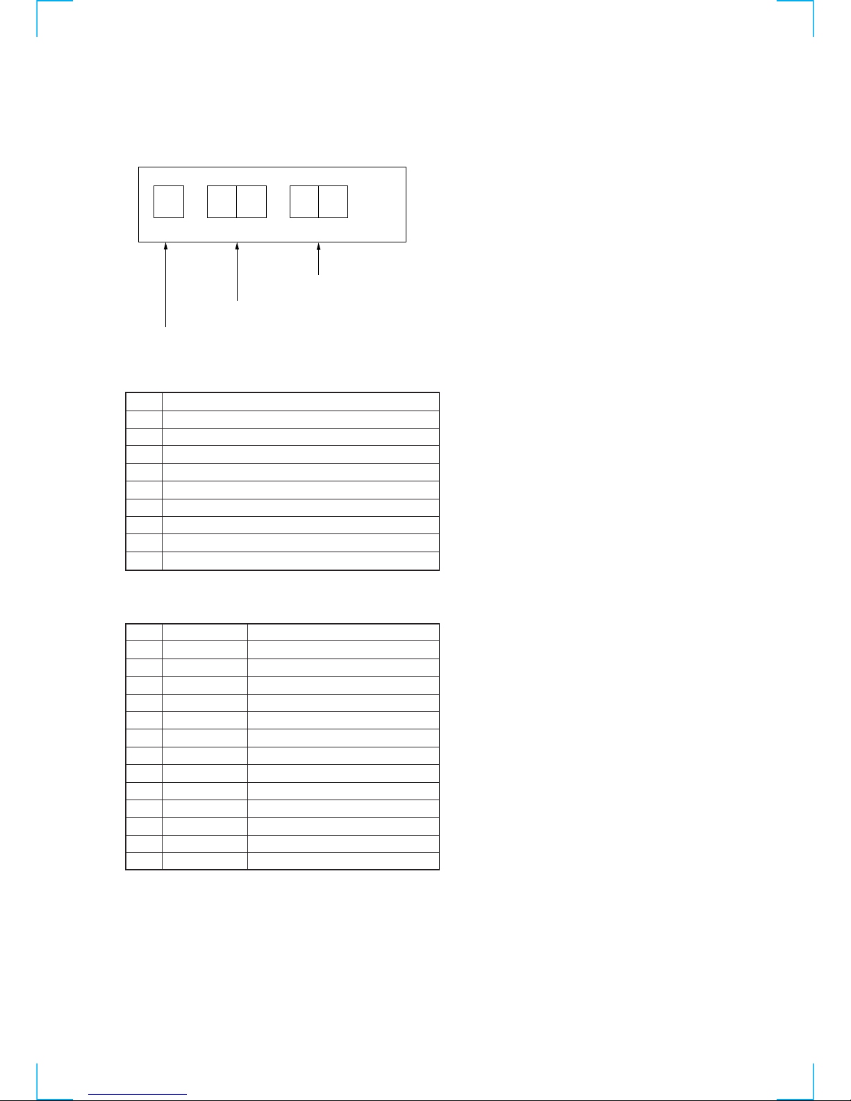
Code
0
1
2
3
4
5
6
7
8
Emergency contents
No emergency
Loading direction cam encoder emergency
Unloading direction cam encoder emergency
T reel rotation emergency
S reel rotation emergency
Capstan rotation emergency
Drum rotation emergency
Cam encoder emergency on initializing
Cassette front loading emergency
Code
0
1
2
3
4
5
6
7
8
9
10
11
12
Cam position
NC
EJECT
CDOWN
ULDEND
TLOAD
HCLEAN
LDEND
RVS
PR
FWDP
FWDP
STOP
FR
VTR mode
Mode except for the following
EJECT (Include Power off)
Cassette down
Tape unload end • Dew stop
In tape loading
In tape loading
Tape loading end
RVS JOG (Include STILL, SLOW)
FWD, FWDP/RVS MECHA inhibit
FWD SLOW, FWD STILL
PB, FWD JOG • STOP (Drum on)
STOP (Drum off • Power off)
FF/REW
SERVICE NOTE
1. ERROR CODE INDICATION
• EMERGENCY CODE and ENCODER DATA and FUNCTION MODE will display to the fluorescent display tube in MECHA
emergency mode.
EMERGENCY CODE
MECHA ENCODER
EMERGENCY CODE (Decimal)
MECHA ENCODER (Decimal)
FUNCTION MODE (Hexadecimal)
— 6 —
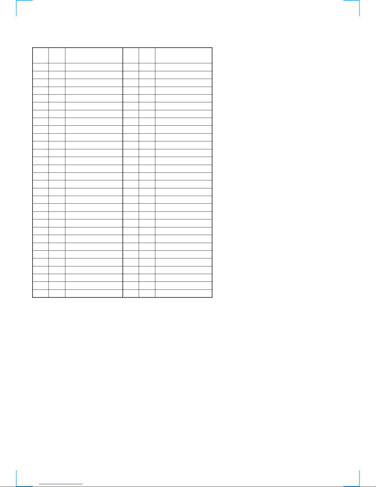
Code
(*1)
00
01
02
03
04
05
06
07
08
09
0A
0B
0C
0D
0E
0F
10
11
12
13
14
15
16
17
18
19
1A
1B
1C
1D
Code
(*1)
1E
1F
20
21
22
23
24
25
26
27
28
29
2A
2B
2C
2D
2E
2F
30
31
32
33
34
35
36
37
38
39
3A
Code
(*2)
80
81
82
83
84
85
86
87
88
89
8A
8B
8C
8D
8E
8F
90
91
92
93
94
95
96
97
98
99
9A
9B
9C
9D
Code
(*2)
9E
9F
A0
A1
A2
A3
A4
A5
A6
A7
A8
AA
AA
AB
AC
AD
AE
AF
B0
B1
B2
B3
B4
B5
B6
B7
B8
B9
BA
Function mode
REW HIGH PB
REC
REC PAUSE
TIMER REC
TIMER REC PAUSE
ORC
VA INSERT
VA INSERT PAUSE
V INSERT
V INSERT PAUSE
A INSERT
A INSERT PAUSE
PB
FWD X1
RVS X1
FWD X2
RVS X2
CUE
REV
CUE LOCK
REV LOCK
EDIT STNBY
DUMMY
FWD STILL
RVS STILL
FED STEP
RVS STEP
FWD SLOW
RVS SLOW
Function mode
Initial
Emergency
Emergency power off
EJECT
EJECT DEW
EJECT power off
ULDEND
STOP DEW
ULDEND power off
HCLEAN
STOP
STOP tape end
STOP tape top
STOP zero
STOP power off
STNBY
STNBY tape top
STNBY zero
EE FWD
EE RVS
FF
FWD SEARCH
FF 0 PB
FF 0 STOP
REW
RVS SEARCH
REW 0 PB
REW 0 STOP
REW PB
REW HIGH
FUNCTION MODE
*1 : After MODE INHIBIT.
*2 : MODE INHIBIT.

1-1
SLV-SE85/SF90/SF99
SECTION 1
GENERAL
This section is extracted from instruction
manual. (SLV-SF99 model)
1-2

1-3

1-4
1-5
1-6

1-7
1-8
1-9
1-10

1-11
1-12
1-13
1-14
1-15
1-16
1-17

1-18
1-19
1-20
1-21
1-22
1-23
1-24
 Loading...