

Page 1

Remote
Commander
Operating Instructions
3-866-294-11(1)
RM-TP502
© 1999 by Sony Corporation
Page 2

Precautions
CAUTION (Lithium battery)
Danger of explosion if battery is incorrectly
replaced. Replace only with the same or equivalent
type recommended by the manufacturer. Discard
used batteries according to the manufacturer's
instructions.
On operation
Before connecting other components, be sure to turn off and
unplug the receiver.
On cleaning
Clean the cabinet, panel and controls with a soft cloth slightly
moistened with a mild detergent solution. Do not use any type of
abrasive pad, scouring powder or solvent such as alcohol or
benzine.
If you have any question or problem concerning your
receiver, please consult your nearest Sony dealer.
About This Manual
• The following icon is used in this manual:
V Indicates hints and tips for making the task easier.
Before You Use the Commander
Understanding the 2 way remote system
This commander operates under a 2 way remote system.
With the 2 way remote system, the component responds
to signals sent from the commander by sending additional
signals (information about the status of the component,
text data, etc.) back to the commander. Thus, operations
are performed as a result of communication between the
commander and the component.
Commander
When using a home entertainment system comprised of
several components compatible with the 2 way remote
system, please restrict 2 way remote system operation to a
single component. Generally, the 2 way remote system is
turned off on all components except for the receiver.
If you would like to turn off the receiver's 2 way remote
system, refer to "Setting up the 2 way remote" in the
operating instructions supplied with the receiver.
Component
Page 3

Table of contents
Preparations 4
Compatible Components and Functions 4
Preparing the Commander 5
Screen Hierarchy 8
Location of Parts and Basic
Operations 9
Front panel 9
Rear panel 10
Operation 11
Basic Operations 11
Example: Operating a CD Player 13
Example: Operating the Tuner 14
Example: Recording from CD to MD 15
Performing Several Commands in Sequence
Automatically (Macro Play) 16
Selecting Sound Fields 17
Adjusting Sound Fields 18
Adjusting the Commander's Operating
Environment 19
Additional information 25
Precautions during use 25
Troubleshooting 26
Specifications 27
Index 27
Page 4

Preparations
Compatible Components and Functions
This chapter describes how to prepare
the remote commander for operation.
Be sure to read this section before
operating.
This unit is romoto control system that utilizes infrared
ra\ s tt> control a receix er and AV components connected
to tlie receix er.
Compatible Components
This unit can be used to operate Sony AV components as
well as AV components made by other manufacturers.
Setup is necessary in order to operate components made
by other manufacturers (see page 19).
Functions
This unit is a 2 way remote commander. Not only does it
transmit infrared rays for operation of the receix'er, it also
receix’es infrared rays emitted by the receix'er to display
characters and other information from components
connected to the receix’er with a CONTROL A1 cord.
Page 5
Preparing the Commander
Please be sure to carry out the procedures described in
"Setting up the commander” on page 6 after inserting the
batteries.
Inserting batteries into the commander
Insert the four size-AA (LR6) alkaline batteries (for
commander operation) and the lithium battery (for
preservation of the commander's internal memory).
1 Remove the battery compartment cover.
Push in direction of
2 Insert the alkaline batteries.
Always insert the negative (-) pole
side of batteries first.
4 Close the battery compartment cover.
After inserting the batteries, touching the touch panel
turns on the light and displays the touch panel (LCD)
adjustment screen. Follow the procedure on the next
page for touch panel adjustment and initial
communication.
^ Touch Panel
Adjust isent ^
\¿ \
fCANCELI
Notes
• The LCD lights up when touched.
• VOL +/-, MUTING and SLEEP can be used even when the
LCD is not lit.
• Pressing BACK LIGHT/COMMANDER OFF turns the
backlight on or off. Holding it down for about 2 seconds turns
the LCD off.
• If the commander is not used for 10 seconds, fhe LCD turns off
automatically (Auto Off function).
■o
fli
Insert the lithium battery.
After wiping the lithium battery thoroughly with a
dry cloth, insert it into the compartment with the
positive (+) pole side facing up.
Page 6
Preparing the Commander
Setting up the commander
Please be sure to carry out the following 5 steps for
preparation of the commander.
The commander's panel is touch sensitive and can be
operated by simply touching it,
1 Remove the touch pen.
When returning the touch pen, always slide it in tip
first.
Caution
Use only the touch pen provided with this unit or the soft tip
of your finger to operate the touch panel. Using a
commercially available writing utensil may damage the panel
and make correct operation impossible. If the tip of the touch
pen is damaged, or the touch pen is iost, please consult your
nearest Sony dealer.
2 Turn CONTRAST to adjust brightness of the LCD.
Touch panel adjustment
3 Adjust the position of the touch panel's LCD.
Touch the center of each of the 4 dots with the touch
pen. When all 4 dots have been touched "Adjusted"
appears, a buzzer sounds, and the initial
communication screen appears.
Touch Pohet
Mjustnent
'4-
Touch the 4 dots with the touch pen.
Adjusted
CONTRAST control
Caution
Touch panel adjustment must be carried out for proper panel
operation. If used without adjustment, the "Touch Panel
Adjustment" screen appears each time the LCD lights up.
Initial communication
4 Press l/(l) on the receiver to turn on the receiver.
Point the commander's transmitter/receiver section toward the receiver's display, and touch OK.
Once initial communication with the receiver has been
established, the commander is ready to operate the
receiver.
CoMmunicQting nith systeM.
SKIP^I
Page 7
Notes
• To ensure gcxxi communication conditions, carry out initial
setup from directly in front of, and close to the receiver.
• Do not move the unit during initial setup.
If a communication error occurs during setup
An error message will be displayed.
• Touching OK wiW return to the step 5 setup screen.
• Touching SKIP goes to the regular screen without
carrying out initial setup. Although operation is
possible in this condition, functions not included on the
receiver will be displayed, and some buttons will not be
operable. Also, the initial setup screen will appear each
time the touch panel is turned on.
when replacing the batteries
To ensure preservation of the commander's internal
memory when replacing batteries, be sure to observe the
following cautions.
When to replace batteries
When the batteries become weak, a warning sounds and a
message is displayed. Replace batteries as instructed by
Replace alkaline
batteries.
Replace lithium
battery.
•Ü
fii
Note
The commander receives and displays data transmitted from the
receiver. Communication errors may occur if the commander's
transmitter/receiver section is not directed properly toward the
receiver's display.
Be sure to point the commander's transmitter/receiver section
towards the receiver's display.
How to remove the lithium battery
Notes
• Disc titles and song titles downloaded from the CD changer are
memorized in the commander. The lithium battery is used for
preservation of this memory^. If the unit is used with an
exhausted battery, the settings memorized in the commander
will be erased. Please replace the battery as soon as the message
appears.
• Replace the alkaline batteries with new batteries as soon as
their charge is exhausted. If the unit is used with exhausted
batteries, exhaustion of the lithium battery used to maintain
memory will be quickened and the memorized settings may be
erased.
• The life span of batteries may be shortened depending on the
conditions in which the commander is used.
• If the alkaline batteries and lithium battery become exhausted
at the same time, replace the alkaline batteries first. Replacing
the lithium battery first will erase the data memorized in the
commander.
• When replacing the alkaline batteries, always replace all 4
batteries with new ones.
• After replacing batteries, be sure to carry out touch panel
adjustment (page 6).
Page 8
Screen Hierarchy
The tollowing diagram shows the basic composition of this unit’s screen hierarciiv.
FUNCTION screen
VI0E01
VI0E02 VI0E03
ifli
TAPE
V/SAT
l^ Q
TUNER
PHONOOMftcîol
Normally, the
FUNCTION screen is
displayed.
To display a different
screen, touch the left
side of the LCD.
DVO/LO
®|
MD/OAT CO 1
nJ
recEw^l
"-l
I 1
M
BVIDEOl
(SCO
®PyD
1 —
|«-T.UT -/•fl[^||-nl"l
1 CHA«t 1 1
...
-
_^HH
•
1 ■
». •
-
DISC
SKIP
•Ill E OUM 1 ! li « |[ !
«
POME» 1
j CM + ~j
1 1
•
•
i
Screens for selection
1
1
and operation of
components
connected to the
recei\iT.
D
' 1
•
•
i POMCB 1
«■ICt
►
“
"1
■
SOUND FIELD screen
Screen for selection and
adjustment of the sound fields
CINCHA STUDIO B
(pages 17-19).
I
SETUP screen
¡SETUP
1 X FUNCTIOHSUSER IP «|
1 FUNCTION HOOK UP «1
f\,00HNL0A0 «1 HACRO «1
1 TOUCH PANEL«t
[auto POHCR «|l
fsYSTIN STA«HT «1 ALL CLEAR
RELOAD... Touch when the song titles of a CD or
BEEP: OSS OFF !
ALARH : RSm OFF 1
MD being played back are not displayed
correctly.
Screen for setting up the
operation environment and
control of components made by
other manufacturers (page 19).
Screen for recording
audio and video from
one component to
another (page 15).
Screen for performing
several commands in
sequence
automatically (pages
22 and 23).
Page 9
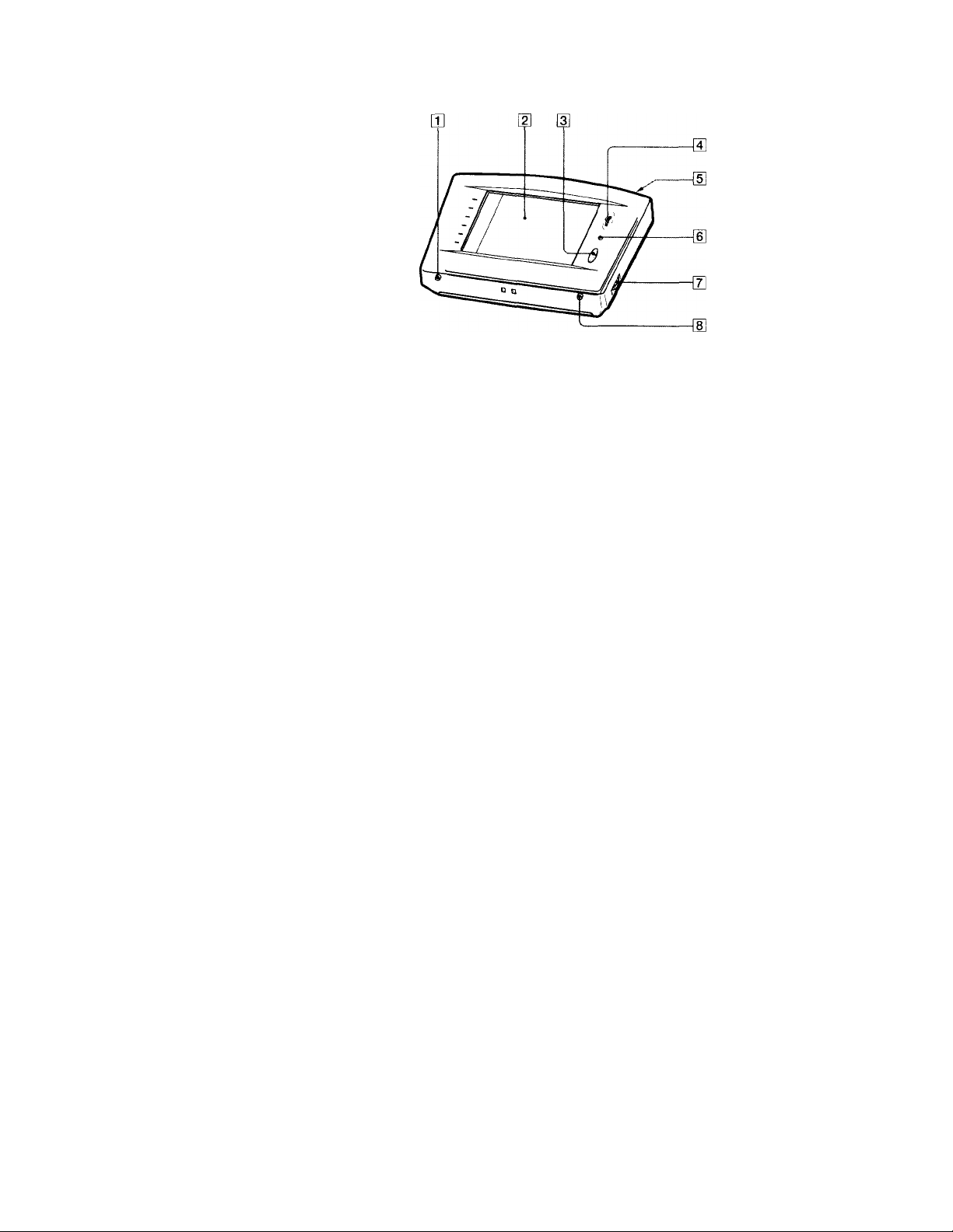
Location of Parts and Basic Operations
Hus chapter provides information about the locations and functions of the buttons and controls on this unit.
Front panel
m BACK LIGHT/COMMANDER OFF
Press to turn the backlight on or off. Hold down for
about 2 seconds to turn the LCD off. When the LCD is
off, press to turn on the LCD and backlight.
• To prolong use of the batteries, the LCD automatically
turns off if there are no commands entered in the touch
panel for 10 seconds.
• To view the LCD display without turning on the backlight,
touch the touch panel when both the backlight and LCD
are off.
O
n
a
5'
3
0
X
Ql
2.
U)
fi)
3
a
a
o>
a'
O
V
fD
S
0’
3
[2] Touch panel
Touch to operate. The commander turns on
automatically.
[3] VOL +/- buttons
Use to adjust the volume of the receiver.
[4] JOG DIAL control
Rotate to scroll through items in a list (etc.).
Push to select the highlighted item.
H] SYSTEM/STANDBY button
Normally used to turn off all Sony components. Can
also be used to turn the receiver on or off depending
on the settings made in the SETUP screen (see page
24).
[1] MUTING button
Use to mute the sound of the receiver.
[3 CONTRAST control
Use to adjust the contrast of the LCD.
[8] SLEEP button
Use to operate the receiver's sleep function. The sleep
settings appear in the receiver's display, not the
commander's LCD.
Page 10

Rear panel
[T] Transmitter/receiver section
Transmits and recei\ es infrared signals to and from
the receiver.
[2 Battery cover
[3] Touch pen
g] SYSTEM/STANDBY button
Normally used to turn off all Sony components. Can
also be used to turn the receiver on or off depending
on the settings made in the SETUP screen (see page
24).
in Touch pen holder
Pull out and insert touch pen when not in use.
10
Page 11

Operation
This chapter explains how to operate the receiver and connected audio/ video components.
Basic Operations
Displaying the FUNCTION screen
To operate components connected to the recei\ er, first
display the FUNCTION screen, then select the component
you wish to operate (CD, MD etc.).
Normally, the FUNCTION screen is displayed. If it is not
displayed, touch FUNCTION to display it.
Touch FUNCTION in the LCD.
---------------
cjlDVD I pomerJ
S|igDVD I'h- ■—! I
[sUB^ITLE^N/OF^
The FUNCTION screen appears.
FUNCTION
sue-TiTLE change
AUDIO CHANGEI
■o
O
[
VIDE01i VOE021 V«E03
' DVO/LD
Ifli
1
i PHONO
O
TfiPE
^
MflCROI
: 'd
MO/DATCO
Q!0
REC EDIT
1
sa
♦
TV/SflT
m
TUNER
Composition of the FUNCTION screen is shown on the
next page.
9 You can change the functions displayed in the FUNCTION
screen
You can set all functions, except TUNER and REC EDIT, to be
displayed or not, using the FUNCTION HOOK UP screen (see
page 21).
11
Page 12

Basic Operations
FUNCTION screen hierarchy
The following diagram shows the composition of the FUNCTION screen hierarchy.
The types of icons that can be displayed on the FUNCTION screen can be set using FUNCTION FIOOK UP in the SETUP
screen. (For details on FUNCTION HOOK UP, see page 21.)
«■Eet wa? «am
wet wa? wai
jH
S5 SS B9
I
□
B H
lOPC
Tv/an
m
sa
nmn
¿1
Tv/an lOK M/ew
raw)
M/awFBCO
'MfRi
■■■
ra
a«aae
®
№
VI0E01
L_JL_i_
SUB
ll~ni^l~ni —
►
-
II
BI -A-B 0 lltinc«l| iKccutt •'
[£«3
CO
DVD/LO
RECEDIT
4
^■”1 1
• 1
iii
KM
JDVD j POMEK
M.
I
S FUNCTION&IISES IK
1 POWER 1
IS^S™
1 1 i 2
► -
II
i « 1
LIST
ll ^ ll =
il 7 11 8 |[ a II ■ 1
liMO i 0 loilTl
[ POHtB 1
3 II »IK 1
« lu-l
GCD BD
12S: IlMMOniUlIC
tta^ tM««ri 0« Mhni«
*30. Frea IiMcaig
131 TirtlPltrMt
1 V me» [ ilKt
▼
J^POMM
1
12
MflCROI
Page 13

Example: Operating a CD Player
This section describes how to operate a CD player
connected to the receiver. Other components can also be
operated in the same way.
For details concerning CD player operation, please refer
to your CD player's operating instructions.
The screens used in the following example are the screens
that appear when using a SONY CD changer with a
CONTROL A1II terminal.
1 Touch FUNCTION.
The FUNCTION screen appears.
Touch L^.
The receiver's function switches to CD and the CD
screen appears.
Selected maker and
category (see page 20).
I r»n
cdT'i
|(c^12t| Janes Live"
1 ^ 8] Let he Be Cool #■
1 ^
R
Í DISC 1
1 SKIP 1
..................
► 1
Disc title*
”"1
■Mi
To operate other functions
Touch SUB. Another set of buttons is displayed and ready
for use.
|9CD B!I3
ISony COl
||cOimNUE|| SHUFFLE ||pROORAM
Í POHER 1
|[ «EPEÍT 1
1 1 II 2 |[ J |( ... 1
II
4 ][ 5 I 6
If”«« 1
rximmcir]
¡>10 11 0 i «TER
1 ITxîtI
To view the LIST
Touch LIST to view the song titles in a Sony CD changer
(5/50/200/300 CD) or MD deck connected by a
CONTROL A1 cord. In this case, the information must be
downloaded from the receiver (see page 21 for details).
The LIST screen can only be displayed when the
FUNCTION is set to CD or DAT/MD.
I®CD OSI
¡Sonij COl
-------------
I®»*“
Jones Live 1
^ 127
Ti«e Out Of Music
128:
129: Sisters or Otheno
FroM Tuscany
130:
131:
Turtle Street
1
.................................
--------------------------
■ -TrrJH
11
^ fExrrl
■o
O
a
Song title*
• Long titles can be read by touching the scroll icon (Q) to
scroll along the title.
• Only displayed when a Sony CD changer (5/50/200/300
CD) or CD player compatible with CD text is connected to
the receiver by a CONTROL A1 cord.
3 Touch ^ to start playback.
9 when the song number or song title is not displayed
correctly
Point the commander toward the receiver and touch RELOAD.
• Touch the disc number to start playing that disc. ^ appears
next to the disc being played.
• Use the JOG DIAL or touch A or ▼ to scroll up or down the list.
• Touch NUMBER to sort in numerical order or touch TITLE to
sort in alphabetical order.
• Touch FUNCTION to return to the FUNCTION screen at any
time.
13
Page 14

Example: Operating the Tuner
This section describes how to operate the tuner.
For details on tuner operation, please refer to the
operating instructions provided with the receiv er.
1 Touch FUNCTION.
The FUNCTION screen appears.
2 Touch [¿1.
The receiver's function switches to TUNER and the
tuner screen appears.
Preset station Station name
Band
• Touch FM/AM to change the band.
• Touch PRESET + or - to search for preset stations.
• Touch TUNING + or - to search for stations that can be
received. ■
• Touch SHIFT to switch memory pages (A, B, C).
• During display of any of the screens, touching FUNCTION
returns to the FUNCTION screen.
Frequency
To operate other functions
Touch SUB to display the icons used for memorizing
briradcast stations and station names.
J.TUNER B
II A2
1
ll ™
1
li
. . . .1 ir
. . . . . . . .
2
li 3. . . . . . .1 r
5
"
li 7
l|i 8 It 9 1
|iS«IFll|i Ô
• To receive manually, touch DIRECT and input the
frequency.
• When memorizing a received broadcast station, memorize
after touching MEMORY.
JL^ L
J
FH-SONV
87. SHHz
1
PONER I
DIRECT
ncnORY
l'Ë'XÏfl
1
1
Viewing the LIST
Touch LIST to view the names of the broadcast stations
downloaded from the receiver (see page 21 for details).
The LIST screen can only be displayed when the
FUNCTION is set to TUNER.
9 When broadcast stations or frequencies are, not dispiayed
properly
Point the commander at the receiver and touch RELOAD.
14
Page 15

Example: Recording from CD to MD
This section describes how to record audio from a CD to
an MD as an example of recording audio/video.
Other operations
Recording from an LD to a \ ideo deck is basically the same
prtKedure. For details on the buttons used in recording, refer to
the operating instructions supplied with the receiver and other
components.
1 Touch FUNCTION.
The FUNCTION screen appears.
2 Touch ri"l.
The RFC EDIT screen appears.
Touch to select the player component (CD in this example).
Because CD is not displayed, Use the JOG DIAL or
touch T to scroll downward through the list. If you
scroll to far, touch ▲ to scroll back up.
PLAYER
4 Touch to select the recorder component (MD/DAT
in this example).
When MD/DAT is touched, the REC EDIT operation
screen appears.
EDIT
144
►
144
. •
i ►
>►1
■ II
i ■
II
5 Touch • in RECORDER: MD/DAT, then touch ► in
PLAYER: CD.
Starts playback from the CD player
■o
O
IB
REC 3)IT 1
Touching A moves list up
Touching ▼ moves list down
When PLAYER is selected, the receiver's FUNCTION
automatically switches to the PLAYER component.
Starts recording on the MD deck.
Recording starts.
The FUNCTION screen returns once the recording
finishes.
To stop recording at any time
Although recording stops automatically in the above
example, recording can also be stopped at any time by
touching ■ in RECORDER.
To stop the recording procedure at any time
Touch FUNCTION to display the FUNCTION screen.
During steps 2 to 3, touching EXIT will also stop the
recording procedure.
15
Page 16

Performing Several Commands in Sequence Automatically
(Macro Play)
The Macro Play function lets you link se\eral IR codes in
sequential order as a single command. The remote
provides 3 macro lists (MACRO 1, 2 and 3). You can
specify up to 10 IR commands for each macro list.
1 Touch FUNCTION.
The FUNCTION screen appears.
Touch
The MACRO screen appears.
The FUNCTION screen can only display up to II
functions. Therefore, you may not find MACRO in the
screen. In this case, set FUNCTION HOOK UP of
other functions to NO and MACRO to YES.
BOX Number
Send key
Notes
• For some mixiels, the receiver cannot operate the Macro Plav
commands as the time between each command is tint short. In
this case, set "WAIT TIME" between each command. To set
"WAIT TIME", refer to "Macro Play setting" on page 22 and 23.
• For some makers other than Sony, there are some commands
that cannot be used in Macro Play.
IMACROI
71
LA
Command ^ .. .
Category SENDING: Outputting the
• Touch SEND to operate Macro Play. The current command
is displayed in black. The finished commands are grayed
out.
' To cancel Macro Play, touch CANCEL. When Macro Play is
not operating, touching CANCEL returns to the
FUNCTION screen.
POUIER 1
IB
si4in
1
}
in
Condition
command
Done!: Outputting is
finished
16
Page 17

Selecting Sound Fields
These sections describe how to select and make
adjustments to the sound fields.
For details concerning sound fields, please refer to the
operating instructions supplied with the receiver.
Displaying the SOUND FIELD screen
Touch SOUND FIELD.
■ SOUND FIELD
i V(DE02 1 V»E03 i OVO/LD
D—
1 TV/SAT
llTUNER
The SOUND FIELD screen appears.
SOUND FIELD
The SOUND FIELD screen hierarchy is shown below.
TftPE
(Bl
PHONO
O
GENRE:
SOUND FIELD OFF
NORMAL SURROUND
CINEMA STUDIO B
i MO/MT CO
M
IMflCROl
RECEDIT
^3
d
SURR
EDIT I
Selecting the sound field
For details concerning which sound fields can be selected,
please refer to the receiver's operating instructions.
1 Touch SOUND FIELD.
The SOUND FIELD screen appears.
2 Use the JOG DIAL or touch A or T to scroll through
the list.
3 Push the JOG DIAL to select the highlighted sound
field or touch the sound field you desire.
A check (✓ ) will appear next to the selected sound
field, and the sound field will change.
. Genre of
sound field
iROlINn FTFI O
I GENRE: II-
SURR
EDIT
3
IflNr SOUND FIELD OFfV—
NORMAL SURROUND
CINEMA STUDIO B
ÌS.FÌÉLd1|Ì
........
eq” If
EQ
EDIT
Turns the equalizer on or off
with each touch
Turns the sound field on or off with each touch
highlighted
by the cursor
■ Selected
sound field
■ Cursor
O
■a
ID
SOUND FIELD screen hierarchy
I
▼
EQ EDIT
*10.Ml
WZRz]
1.4k№
*10.M
[ê« t!
SOU N D F IEL D E» C»ir
FMWT BMS (MIN:
Finn MX FRCMMCV:
Finn TKIU FWOUiNCV:
COnER MtS aUM:
[ - Jf +
A !
17
Page 18

Adjusting Sound Fields
S<.>und fields can be adjusted with the following 3 items:
• EQ EDIT (frequency band adjustments)
• SURROUND EDIT (surround parameter adjustments)
• LEVEL (speaker volume adjustments)
For details on what can be adjusted, refer to the operating
instructions supplied with the receiver.
To adjust the frequency bands
1 Touch EQ EDIT on the SOUND FIELD screen.
The EQ EDIT screen appears.
2 Select the item that you wish to adjust (output
speaker, sound range, frequency, or gain).
To adjust the surround parameters
1 Touch SURR EDIT on the SOUND FIELD screen.
The SURROUND EDIT screen appears.
SOUND FI ELD SURItOUNO EDIT
EFFECT
HALL
TYPE
REVERB
TIME
LFE MIX
LEVEL
0 RANGE
COMPRESSOR
2 Adjust as desired.
EFFECT: Higher values increase the "presence" of the
surround effect.
WALL TYPE: Use to simulate different sonic
environments.
REVERB TIME: Use to control the spacing of the early
reflections.
LFE MIX LEVEL: Touch |V] or [3 to select the desired
value.
D.RANGE COMPRESSOR: Touch 0 or 0 to select
the desired value.
3 Touch EXIT when adjustment is finished.
^ SOFT It ~ Д: * Д
SWRT LONG ll ~ lii * M
НИП »«ЕИ
■НИИ
fEXITl
3 Touch
value.
4 Repeat steps 2 and 3 when there is more than one -
item that you wish to adjust.
I to adjust to the desired
To display other items, use the JOG DIAL or touch A
or ▼ to scroll through the list,
5 Touch EXIT when adjustment is finished.
Notes
• hems that cannot be adjusted due to the current speaker
settings or sound field mode are grayed out.
• If the alarm sounds, or all items appear to be grayed out, touch
RELOAD.
18
Notes
• Items that cannot be adjusted due to the current speaker
settings or sound field mode are grayed out.
• If the alarm sounds, or all items appear to be grayed out, touch
RELOAD.
Page 19

To adjust the speaker volume
1 Touch LEVEL on the SOUND FIELD screen.
The LEVEL screen appears.
Adjusting the Commander's Operating Environment
The following explanations allow you to adjust various
settings and customize the commander's operating
environment.
UrjiTii.iM
3CillK[i
LIÍT
'ñU&
'ClCmD
SOUND FIELD
V
CENTER
mm
REAR
mm
■HHIIIII cbeS boostI
MOOFER
REAR
LEFT CENTER i»iei?T-li ~ Ml * 1
MIANCE
LEVEL
Í TEST 1
i TOME 1
lExrJ
2 Adjust as desired.
Touch f« 1 or rn to adjust to the level of the
corresponding speaker.
3 Touch EXIT when adjustment is finished.
To listen to the adjusted sound and check its balance
Touch TEST TONE.
To emphasize the low range
Touch BASS BOOST.
Notes
• Items that cannot be adjusted due to the current speaker
settings or sound field mode are grayed out.
• If the alarm sounds, or all items appear to be grayed out, touch
RELOAD.
Displaying the SETUP screen
To adjust the operating environment, first display the
SETUP screen.
Touch SETUP.
• SETUP
\
V»E01
TV/SAT
vioEoa
I TAPE
1 vneo3
MO/DAT CO
OVD/LD
;®
m Q
MRCROI
IrUNCA \ PHONO
O
The SETUP screen appears.
ISETUP
FUNCTIOH&USER IR 4|
rr
FUNCTION HOOK UP «|
1
|;L DOWNLOAD «Il MACRO «]
MNEL«]| BEEP;(B11 OFF |
1 TOUCH
|auto POWER «11 ALARM ilBÑI OFf]
iSYSTEnSTAN06Y^II ALL CLEAR 4
Ireceint
1 B3
♦
à
O
■Ü
A
19
Page 20

Adjusting the Commander's Operating Environment
Registering the connected components
The following procedure lets \ ou setup the component
commander to operate the components connected to the
recei\ er.
When carrying out this operation, make sure that the receiver's
power is on, and be sure to point the commander's transmitter/
receiver section toward the display on the receiver.
1 Touch SETUP.
The SETUP screen appears.
2 Touch FUNCTION&USER IR.
The FUNCTION&USER IR screen appears.
£ FUNCTION&USER IR
_______________________±
VIDEOl : Sony VTR3
VIDE02: Sony VTR2
VIDEQ3:
DVD/LD:
TV/SAT: Sony TV
r ^ I
Select the function that you wish to register (Ex;
VIDE01).
To display other items, use the JOG DIAL or touch ▲
or T to scroll through the list.
The FUNCTION&USER IR:CATEGORY screen
appears.
X FUNCIIONItUSER IR: CRIEGORV
îOUN['
I VCR
_________________________
JVC VTRl
Pioneer DVD
TV
LD
DVD
VIDEO CD
Select the type of component connecteci (Ex: VCR).
T(^ display other items, use the jOG DIAL or touch ▲
or ▼ to scroll through the list.
The EUNCTlON&rUSER IU:MAKER CODE screen
appears.
^ FUNCTlONliUSER IR: HAKER CODE
SOUND
FIELD I Sony VTRl
Sony VTR2
Sony VTR.3
Admiral VCR
Aiwa VCR-1
5 Touch the remote controller mode of the connected
component (Ex: Sony VTR1).
The component selected in steps 4 to 5 will be
registered at the function selected in step 3, and the
SETUP screen reappears. A long beep sound is emitted
to indicate that registration was successful. Operation
is now possible from the FUNCTION screen.
If a series of short beeps is emitted, redo the
registration procedure. If this occurs, make sure the
receiver is turned on and that the commander is
pointing toward the receiver during operation.
To stop registration at any time
Touch EXIT during step 2 or touch CANCEL during steps 3 to 5.
Notes
• All icons may not be displayed when registering components
made by certain manufacturers.
• Some commands may not function even though they are
displayed when registering components made by certain
manufacturers.
20
Page 21

FUNCTION screen setup
Up to U components can bo displayed on the FUNCTION
screen. Only connected components appear on the
FUNCTION screen.
1 Touch SETUP.
The SETUP screen appears.
2 Touch FUNCTION HOOK UR
The FUNCTION HOOK UP screen appears.
FUNCTION HOOK UP
▲
VIDE01~
VIDE02: NO
VIDE03:
DVD/LO: NO
TV/SAT:
3 Select the function not to be displayed and touch
NO.
To display other items, use the JOG DIAL or touch A
or T to scroll through the list.
The selected component is set not to appear and the
SETUP screen reappears.
To display the components set not to be displayed
Touch YES instead of NO in step 3.
WETsm
YES
HZQ]
Kim NO
NO
2 Touch DOWNLOAD.
The DOWNLOAD screen appears.
I
X, DOHNLOAO
FUNCTION NAME
TUNER PRESET NAME
CD riEnO
Touch to select the data you wish to download and
press:
FUNCTION NAME: Names of connected components.
TUNER PRESET NAME: Broadcast station names etc.,
memorized in receiver.
CD MEMO: CD song titles or disc titles etc., from a
Sony CD changer (5/50/200/300 CD) connected to
the receiver with CONTROL A1 cord.
Downloading starts, and the progress is displayed.
During this time, please leave the commander's
transmitter/receiver section pointed toward the
display on the receiver.
■o
O
«
? Components that have been registered (see page 19) are set
to "YES" automatically.
Note
The FUNCTION screen can display up to 11 functions. To display
USER, MACRO, etc., set FUNCTION HOOK UP of other
functions to NO.
Downloading receiver data
Various types of data can be downloaded from the
receiver.
When carrying out this operation, make sure that the receiver's
power is on, and be sure to point the commander's transmitter/
receiver section toward the display on the receiver. Also, operate
the commander at a distance of about 1-2 meters from the
receiver.
1 Touch SETUP.
The SETUP screen appears.
when you touch CANCEL, the data downloaded
before you touched CANCEL will be saved.
When downloading has finished, the DOWNLOAD
screen reappears. A long beep sound is emitted to
indicate that the downloading was successful.
If a series of short beeps is emitted, redo the
downloading procedure. If this occurs, make sure the
receiver is turned on and that the commander is
pointing toward the receiver during operation.
4 Repeat step 3 to download other data.
5 Touch EXIT.
Downloading finishes and the SETUP screen
reappears.
21
Page 22

Adjusting the Commander's Operating Environment
Macro Play setting
riu' k'llmving is iin example of hou to set tlie eommaiiJ
■TOWLK" tof SONY VTK I in BOX 2 of MACRO 1. Se-t
other a'lnmands in a similar manner.
1 Touch SETUP.
VI0E01
FUNCTION
SOUND
FIELD
TV/SflT
LIST
M
SUB
TUNER
SETUP
RELOAD
The SETUP screen appears.
2 Touch MACRO.
SETUP
; g FUNCTION&USER IR -»|
I FUNCTION HOOK UP ♦!
I^DONNLOAD .>|| MACRO ♦!
(touch panel♦II BEEP: [ON] OFF ]
I AUTO POWER ♦]!
I SrSTEn STANDBY ♦][
VtOE03 DVO/LD
VIDE02
TftPE
MO/OOT CO
Q]
PHONO0MflCROt RECEOIT
M
m
ALARM: ® OFf]
ALL CLEAR ♦]
4 Select the BOX Number.
Select the BOX Number you want to register the
command. You can program up to 10 commands in
one area.
The CATEGORY list appears.
5 Select the CATEGORY.
HACROI SETUP: SELECT CPTEGOflV
TV
LD
OVD
VIDEO CO
nACROI BOX No.2
The setting screen for Macro Play appears.
3 Select the MACRO Number.
I 5 MACRO
IMCnO SETUP: SELECT IIACRO No.
MRCROi MRCR02 iMflCfi03
;
a
a
u
Select MACRO 1, MACRO 2 or MACRO 3 in which
you want to register the macro program.
The BOX Number list appears.
22
Select the component category for the BOX Number
you selected in step 4.
The MAKER list appears according to the category
you selected.
When the maker is Sony only, go to step 7.
You can select "WAIT TIME"other than audio
components as the CATEGORY.
Page 23

6 Select the MAKER.
FUNCTiaNtUSER IR: RAKER CODE
Í0UND
I Sony VTRl
Sony VTR2
Sony VTR3
Admiral VCR
Aiwa VCR-1
Select the maker from the maker list.
The COMMAND list appears according to the maker
you selected.
7 Select the COMMAND.
^ mcmi SETUP: select csrhand
C To clear the programmed MACRO
S.?Ioct the BOX Number of the MACRO you want to dear in step
4, Si'lect "MACRO CLEAR" in the CATEGORY in step 5. The
items of the BOX are deared.
V To set "WAIT TIME"
Select the BOX Number of the MACRO you want to set the wait
time for in step 4, Select "WAIT TIME" in the CATEGORY in step
3.
The wait time list (1 to 10 second in 1 second increments)
appears. Select the time you want to delay. After you selected, the
BOX Number list reappears.
If you press ALL CLEAR on the receiver, all the registered
MACRO programs are cleared.
Note
If you want to set the command "POWER" for STR-DA355ES as
well as additional commands for STR-DA555ES (for example,
"switch the function to VIDEO 1") to be performed in succession
as a MACRO, set a 1 second WAIT TIME between each
command.
■o
O
(D
HACmi BOK N0.2
r CANCEL
Select the command you want to register.
The items selected in step 5 to 7 are registered in the
box selected in step 4.
The BOX Number list reappears.
23
Page 24

Adjusting the Commander's Operating Environment
Other setup
SETUP
I ^ FUNCTIOmUSER IR -»|
ji FUNCTION HOOK up ■»!
f ^ OOHNLDAD -»II MACRO ■»!
[ touch PANEL-»||
□
([auto poher -»ll^
(system STAH08V ■►l|i ALL CLEAR '»]
■ Adjusting the position of the touch panel
(LCD)
Adjust the position of the LCD when it shifts from the
normal operating position.
1 Touch TOUCH PANEL on the SETUP screen.
The TOUCH PANEL ADJUSTMENT screen appears.
2 Touch the center of each of the 4 dots.
(For details, see "Touch panel adjustment" on page 6.)
"Adjusted" appears in a short while and long beep is
emitted.
■ Setting the AUTO POWER function
ON: When a video function (DVD, etc.) is selected, the
commander sends numerous codes to the
appropriate Sony AV components. At this time, the
TV automatically switches to VIDEO 1 input mode.*
Example) When you select DVD, the following
occurs..
1 The receiver switches to DVD player operation
mode.
2 The TV turns on.
3 The DVD player turns on.
4 The TV automatically selects VIDEO 1 input.
OFF: When a function is selected, the Commander code
applies only to receiver operation.
BEEP ;|0N1 OPE I
ALARM; ¡ON] OFf|
■ Setting the operation sound on or off
A beep can be set to sound or not sound when the touch
panel is touchecf.
Touch ON (sound) or OFF (no sound) in BEEPtON
OFF in the SETUP screen.
■ Setting the warning aiarm on or off
A warning alarm can be set to sound or not sound when a
communication error has crccurred.
Touch ON (sound) or OFF (no sound) in ALARM:ON OFF in the SETUP screen.
■ Returning settings to their factory preset
settings
Use this function to erase all memorized settings and
return them to their factory presets.
Please note that once erased, settings can not be returned.
When carrying out this operation, make sure that the receiver's
power is on, and be sure to point the commander's transmitter/
receiver section toward the display on the receiver.
1 Touch ALL CLEAR on the SETUP screen.
2 Touch OK.
* Switching to VIDEO 1 input may not be automatic on all Sony
TVs. This is because some TVs cannot receive remote control
codes immediately after being turned on.
■ Changing the function of the SYSTEM/STANDBY button
ALL OFF: Switches power of all Sony AV components
off.
ON/OFF: Switches only the receiver on or off.
24
Page 25

Additional
Precautions during use
information
On installment
Do not drop the commander or subject it to strong
\ ibration as this could cause damage.
On the touch pen
Use only the touch pen provided with this unit or the soft
tip of your finger fo operafe fhe touch panel. Using a
commercially available wrifing ufensil may damage fhe
panel and make correcf operafion impossible. If fhe tip of
fhe touch pen is damaged, or fhe fouch pen is lost, please
consult your nearest Sony dealer.
On battery life
When the backlight is not neccessary, do not press BACK
LIGHT/COMMANDER OFF to turn on the LCD. Touch
the touch panel to turn on just the LCD. The life of the
battery will be prolonged. The life of the battery may be
shortened depending on the conditions in which the
commander is used.
On handling
The touch panel (display section) is made of glass.
Twisting the touch panel, dropping the unit, placing your
elbow (etc.) on it, or placing heavy objects on top of it,
may break the touch panel and cause bodily harm due to
glass fragments.
On cleaning
Clean the cabinet, panel and controls with a soft cloth
slightly moistened with a mild detergent solution. Do not
use solvent such as thinner, benzine, or alcohol as these
will damage the rear panel.
>
a.
a
rt*'
5'
3
¡¡_
5'
-♦»
o
3
fil
rt*
5*
3
25
Page 26

Troubleshooting
If vou experience nny of fhe following difficulfies wliile
using fhe commander, use fliis fronhleslnx>fing guide fi'
help \'on remedy fhe problem. Should any problem
persisf, consult your nearest Sc>n\’ dealer.
Operation can not be done with the commander.
^ Check that the receiver and components are
connected correctly.
^ The commander and receiver are too far apart.
^ Make sure that there are no objects between the
commander and receiver.
Make sure that the receiver's power is turned on.
^ The commander's transmitter/receiver section is
not pointed at the receiver.
^ The commander's batteries are exhausted. Replace
with new alkaline batteries (see page 7).
^ There is an invertor system florescent tight near the
commander or receiver. Please place away from
the florescent light.
^ Make sure you have selected the correct function
on the remote.
When you operate a programmed non-Sony
component, the remote may not function properly
depending on the make and model of the
component.
The receiver's functions and modes do not
correlate with the displays on the commander.
Initial communication setup has not been done.
Use after first carrying out initial communication
setup (see page 6).
^ The commander was not pointed at the receiver
when it was turned ON. Touch RELOAD, and
download component data (see page 8).
^ Select the correct function using the commander.
The SOUND FIELD function does not work.
^ If the receiv er has the 5.1 INPUT jacks, the SOUND
FIELD function becomes inoperable whenever you
select the component connected to the jacks.
Commands of components made by
manufacturers other than Sony do not function.
When registering components made by certain
manufacturers, some commands may not function
even though they are displayed.
"5.1INPUT" cannot be selected from the function
screen even though the receiver has the 5.1
INPUT jacks.
A communication error has occurred. Point the
remote towards the receiver and select "5.1INPUT"
from the function screen again.
LCD does not appear.
^ The LCD is not turned on. Touch the touch panel.
Contrast is too light or too dark.
Use the CONTRAST control to adjust the contrast
of the LCD (see page 6).
When a CD player, tape deck, or MD deck is
connected to the receiver via CONTROL A1II jacks.
Auto Function does not work properly.
^ Reprogram the remote (see page 19).
26
Page 27

Specifications
Index
Operating system
Liquid crystal touch
panel
Liquid crystal size
3.8 inches
(256 X 200 dots)
Liquid crystal type
Reflection system
(Monochrome type)
Touch panel Resistant membrane
system
Analog type
Power requirements
For operation: DC 6V
(Type AA alkaline
batteries)
For memory
preservation:
DC3V
(CR2032 lithium
battery)
Maximum external dimensions
(width X height x depth, including
projecting parts and controls)
160 X 111 X 46 mm
Mass 290 g (Main unit only
including touch pen)
Design and specifications are subject
to change without notice.
A, B
Battery 5, 7
C
CD player 13
D
Downloading receiver data 21
E. F, G
Front panel 9
FUNCTION Screen 11,12
setup 20
H, I. J, K, L
Operating components
CD player 13
Recording 15
Tuner 14
M, N, O
Macro Play 16, 22, 23
P. Q, R
Rear panel 10
Recording 15
Registering the connected
component 19
Setup
commander 6
environment 19-24
FUNCTION screen 20
SETUP screen 19
SOUND FIELD 17-19
>
a
a
H*’
5‘
3
s'
•4*
0
n
3
0
3
T, U, V. W, X, Y, Z
Tuner 14
27
 Loading...