

Sony RMT-D108E Service Manual

MICROFILM
SERVICE MANUAL
Chinese Model
Hong Kong Model
Singapore Model
Taiwan Model
CD/DVD PLAYER
DVP-K330
RMT-D108E
SPECIFICATIONS
– Continued on next page –
– 2 –
WARNING!!
WHEN SERVICING, DO NO T APPR O A CH THE LASER
EXIT WITH THE EYE TOO CLOSELY. IN CASE IT IS
NECESSARY TO CONFIRM LASER BEAM EMISSION,
BE SURE TO OBSERVE FROM A DISTANCE OF
MORE THAN 25 cm FROM THE SURFACE OF THE
OBJECTIVE LENS ON THE OPTICAL PICK-UP BLOCK.
CAUTION:
The use of optical instrument with this product will increase eye
hazard.
SAFETY-RELATED COMPONENT WARNING!!
COMPONENTS IDENTIFIED BY MARK ! OR DOTTED
LINE WITH MARK ! ON THE SCHEMA TIC DIAGRAMS
AND IN THE PARTS LIST ARE CRITICAL TO SAFE
OPERATION. REPLACE THESE COMPONENTS WITH
SONY PARTS WHOSE PART NUMBERS APPEAR AS
SHOWN IN THIS MANUAL OR IN SUPPLEMENTS PUBLISHED BY SONY.
CAUTION
Use of controls or adjustments or performance of procedures
other than those specified herein may result in hazardous radiation exposure.
SAFETY CHECK-OUT
1. Check the area of your repair for unsoldered or poorly-soldered connections. Check the entire board surface for solder
splashes and bridges.
2. Check the interboard wiring to ensure that no wires are
“pinched” or contact high-wattage resistors.
3. Look for unauthorized replacement parts, particularly transistors, that were installed during a previous repair. Point them
out to the customer and recommend their replacement.
After correcting the original service problem, perform the following
safety checks before releasing the set to the customer:
4. Look for parts which, though functioning, show obvious signs
of deterioration. Point them out to the customer and recommend their replacement.
5. Check the B+ voltage to see it is at the values specified.

– 3 –
Service Note ............................................................................ 4
1. GENERAL
Getting Started ........................................................................ 1-1
Playing Discs ........................................................................... 1-3
Using Various Functions with the Control Menu ..................... 1-5
Enjoying Karaoke .................................................................... 1-10
Settings and Adjustments........................................................ 1-11
Self-Diagnosis Function .......................................................... 1-14
Index to Parts and Controls..................................................... 1-15
2. DISASSEMBLY
2-1. Case Removal............................................................... 2-1
2-2. MB-82 Board Removal.................................................. 2-1
2-3. Power Block Removal ................................................... 2-1
2-4. AU-214 Board Removal ................................................ 2-1
2-5. Tray Cover Removal ..................................................... 2-2
2-6. Front Panel Removal .................................................... 2-2
2-7. Mechanism Deck Removal ........................................... 2-2
2-8. Tray Removal ................................................................ 2-2
2-9. Optical Pick-up Removal............................................... 2-3
2-10. Belt, Loading Motor (M001),
MS-29/46, TK-51 Board Removal ................................. 2-3
2-11. Internal Views ................................................................ 2-4
2-12. Circuit Boards Location ................................................. 2-5
3. BLOCK DIAGRAMS
3-1. Overall Block Diagram .................................................. 3-1
3-2. RF/Servo Block Diagram .............................................. 3-3
3-3. Signal Process/Video Block Diagram ........................... 3-5
3-4. System Control Block Diagram ..................................... 3-7
3-5. Audio Block Diagram..................................................... 3-9
3-6. Interface Control Block Diagram................................... 3-11
3-7. Power Block Diagram.................................................... 3-13
4. PRINTED WIRING BOARDS AND
SCHEMATIC DIAGRAMS
4-1. Frame Schematic Diagram ........................................... 4-3
Frame (1) Schematic Diagram...................................... 4-3
Frame (2) Schematic Diagram...................................... 4-5
4-2. Printed Wiring Boards and Schematic Diagrams ......... 4-7
TK-51 Printed Wiring Board .......................................... 4-7
TK-51 Schematic Diagram ............................................ 4-11
MS-29/46 Printed Wiring Board and
Schematic Diagram....................................................... 4-13
MB-82 Printed Wiring Board ......................................... 4-15
MB-82 (AV DECODER) Schematic Diagram................ 4-19
MB-82 (SDRAM) Schematic Diagram .......................... 4-21
MB-82 (SERVO DSP) Schematic Diagram .................. 4-23
MB-82 (DRIVE) Schematic Diagram ............................ 4-25
MB-82 (ARP) Schematic Diagram ................................ 4-27
MB-82 (SYSTEM CONTROL) Schematic Diagram...... 4-29
MB-82 (HGA) Schematic Diagram................................ 4-31
MB-82 (CLOCK GENERATOR)
Schematic Diagram....................................................... 4-33
MB-82 (KARAOKE DSP) Schematic Diagram ............. 4-35
MB-82 (DAC) Schematic Diagram ................................ 4-37
MB-82 (BIAS) Schematic Diagram ............................... 4-39
AU-214 Printed Wiring Board ....................................... 4-41
AU-214 Schematic Diagram ......................................... 4-43
FL-103 Printed Wiring Board ........................................ 4-45
FL-103 (FUNCTION SWITCH)
Schematic Diagram....................................................... 4-47
FL-103 (IF CON) Schematic Diagram .......................... 4-49
FR-153 Printed Wiring Board........................................ 4-52
FR-153 Schematic Diagram.......................................... 4-53
MC-121 Schematic Diagram......................................... 4-55
MC-121 Printed Wiring Board ....................................... 4-57
VR-71 Printed Wiring Board.......................................... 4-58
VR-71 Schematic Diagram ........................................... 4-59
HS-030SH/030SU Printed Wiring Board ...................... 4-61
HS-030SH/030SU Schematic Diagram ........................ 4-63
5. IC PIN FUNCTION DESCRIPTION
5-1. System Control Pin Function
(MB-82 Board IC202) .................................................... 5-1
6. TEST MODE
6-1. General Description ...................................................... 6-1
6-2. Starting Test Mode ........................................................ 6-1
6-3. Syscon Diagnosis.......................................................... 6-1
6-4. Drive Auto Adjustment................................................... 6-5
6-5. Drive Manual Operation ................................................ 6-7
6-6. Mecha Aging.................................................................. 6-9
6-7. Emergency History ........................................................ 6-9
6-8. Version Information ....................................................... 6-10
6-9. Video Level Adjustment................................................. 6-10
7. ELECTRICAL ADJUSTMENTS
7-1. Power Supply Adjustment............................................. 7-1
1. Power Supply Check (HS-030SH/030SU BOARD)...... 7-1
7-2. Adjustment of Video System......................................... 7-2
1. Video Level Adjustment (MB-82 BOARD) .................... 7-2
2. S-terminal Output Check (MB-82 BOARD) .................. 7-2
3. Checking Component Video Output B-Y
(MB-82 BOARD)............................................................ 7-2
4. Checking Component Video Output R-Y
(MB-82 BOARD)............................................................ 7-2
5. Checking Component Video Output Y
(MB-82 BOARD)............................................................ 7-3
6. Checking S Video Output S-C (MB-82 BOARD) .......... 7-3
7-3. Adjustment Related Parts Arrangement ....................... 7-4
8. REPAIR PARTS LIST
8-1. Exploded Views ............................................................. 8-1
8-1-1. Case Assembly......................................................... 8-1
8-1-2. Front Panel Assembly .............................................. 8-2
8-1-3. Chassis Assembly .................................................... 8-3
8-1-4. Mechanism Deck Assembly..................................... 8-4
8-2. Electrical Parts List........................................................ 8-5
TABLE OF CONTENTS
Section Title Page Section Title Page
– 4 –
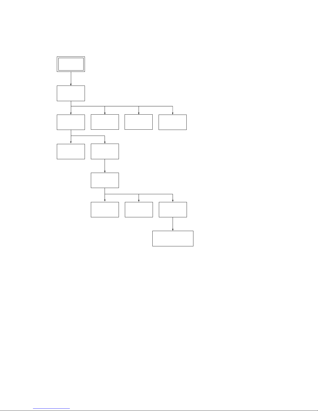
SERVICE NOTE
Set
Case
(Page 2-1)
Power
Block
(Page 2-1)
AU-214 Board
(Page 2-1)
Mechanism
Deck
(Page 2-2)
Front Panel
(Page 2-2)
Tray Cover
(Page 2-2)
Optical Pick-up
(Page 2-3)
TK-51 Board
(Page 2-3)
Belt
(Page 2-3)
Loading Motor (M001),
MS-29/46 Board
(Page 2-3)
Tray
(Page 2-2)
MB-82 Board
(Page 2-1)
1. DISASSEMBLY
• This set can be disassembled in the order shown below.
– 5 –
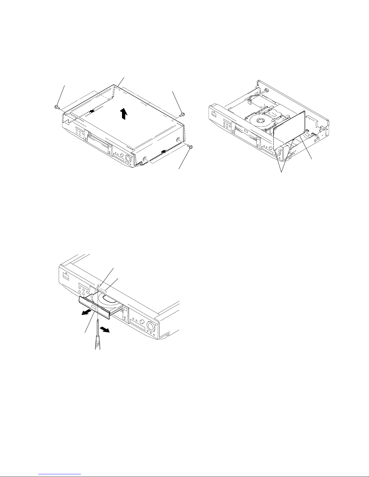
4. HOW TO SERVICE MB-82 BOARD
1) Remove the case from the set. (Refer to 2-1)
2) Remove the MB-82 board. (Refer to 2-1)
3) Set the MB-82 board as shown in Fig. 3.
Note: Do not disconnect wiring, except FMA-7/9/10.
Fig. 3
2. NOTE ON REMOVE THE CASE
1) Remove seven screws. (See Fig. 1)
2) Open the side of case. (See Fig. 1)
3) Remove the case as lift straight. (See Fig. 1)
Fig. 1
3. DISC REMOVAL PROCEDURE
(at POWER OFF)
1) Insert a tapering driver into the aperture of the unit bottom,
and move the lever of chuck cam in the direction of the arrow
A. (See Fig. 2)
2) Draw out the tray in the direction of the arrow B, and remove
a disc. (See Fig. 2)
Fig. 2
Two screws
Three screws
Case
Two screws
Lever of chuck cam
Aperture
Tray
A
B
MB-82 board
grooves
1-1
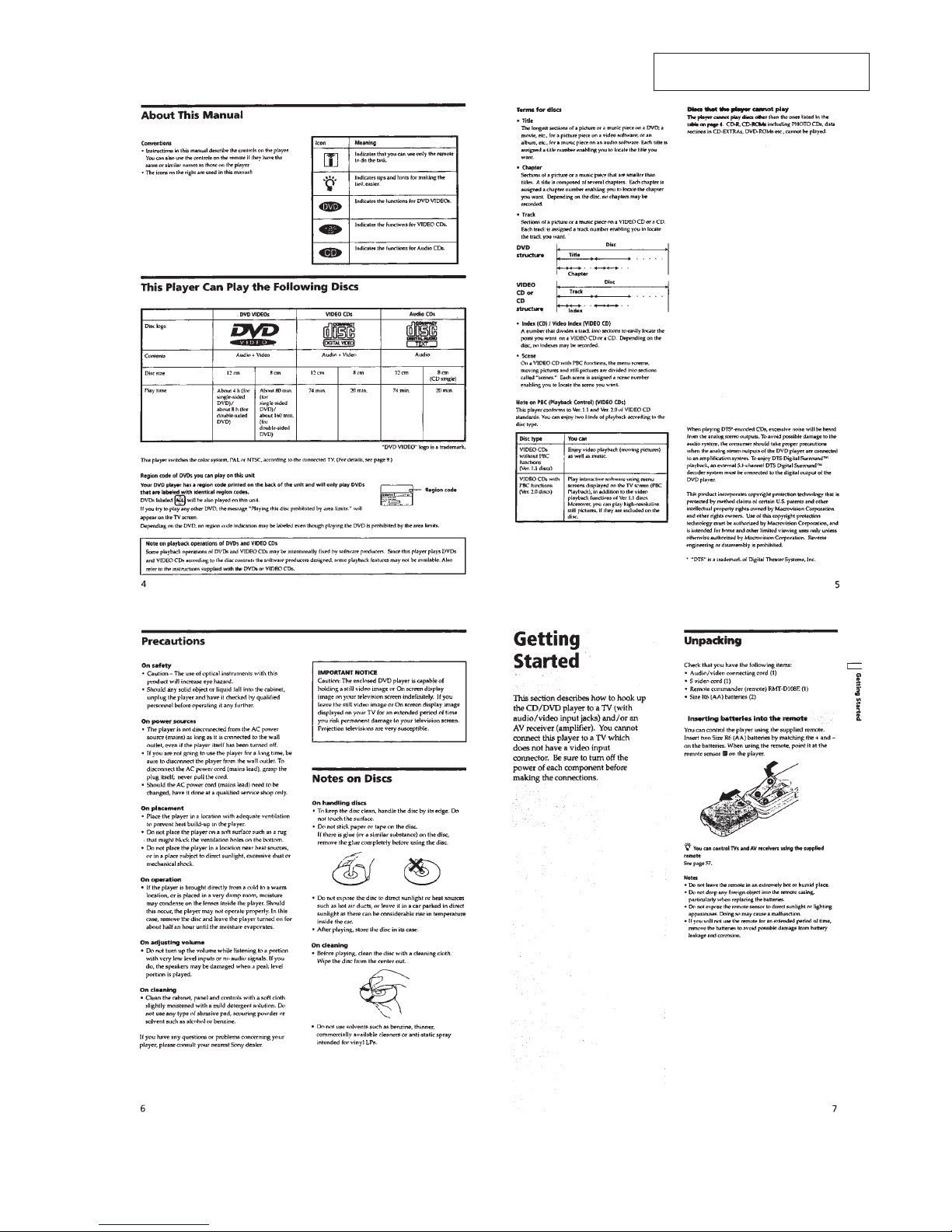
SECTION 1
GENERAL
This section is extracted from instruction manual (3-866-505-11).
DVP-K330
1-2
1-3
1-4

1-5
1-6

1-7
1-8
1-9
1-10
1-11
1-12
1-13
1-14
1-15
1-15 E
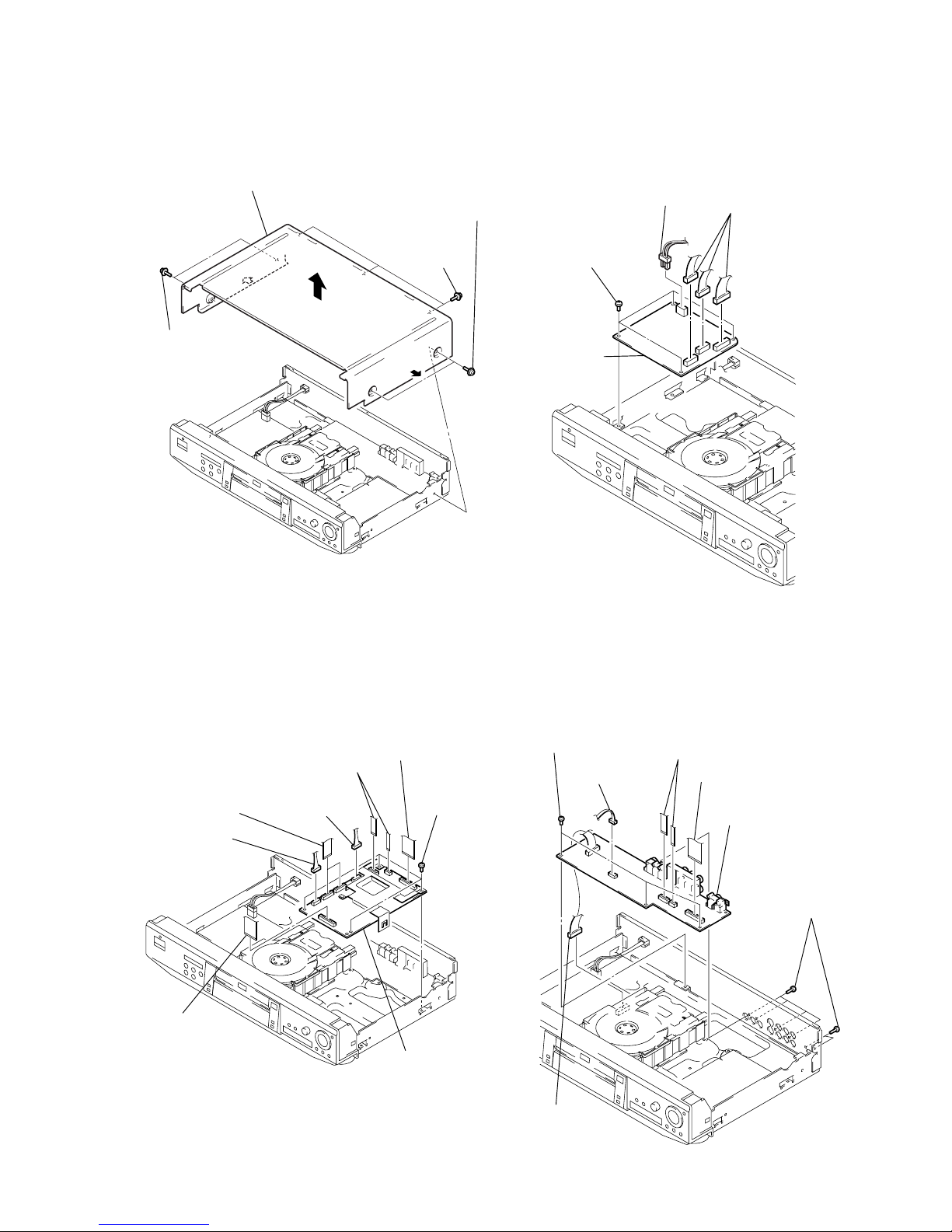
2-1
Note: Follow the disassembly procedure in the numerical order given.
2-1. CASE REMOVAL 2-3. POWER BLOCK REMOVAL
2-2. MB-82 BOARD REMOVAL
2-4. AU-214 BOARD REMOVAL
SECTION 2
DISASSEMBLY
DVP-K330
4 Case
3 Two screws
2 Two screws
1 Three screws
4 Two flat cables
(CN004, 008)
2 Two flat cables
(CN002, 003)
6 Flat cable
(CN006)
8 MB-82 board
7 Four screws
(B3)
3 Connector
(CN001)
1 Connector
(CN011)
5 Flat cable
(CN005)
1 Connector
(CN101)
2 Three connectors
(CN201, 202, 203)
3 Four screws
(B3)
4 Power block
6 Three screws
(B3)
5 Six screws
(B3)
2 Connector
(CN402)
1 Connector
(CN201)
3 Two flat cables
(CN303, 403)
4 Flat cable
(CN301)
7 AU-214 board

2-2
2-5. TRAY COVER REMOVAL 2-7. MECHANISM DECK REMOVAL
2-6. FRONT PANEL REMOVAL
2-8. TRAY REMOVAL
4
Tray cover
2
Pull the tray in the
direction of the
arrow B.
1
Insert a tapering driver into the aperture of the
unit bottom, and move the lever of chuck cam
in the direction of the arrow A.
3
Two claws
B
A
4
Screw
(B3)
2 Connector
(CN842)
3 Flat cable
(CN006)
1 Connector
(CN203)
5 Two screws
(B3)
9 Claw
8 Claw
!º Front panel
6 Boss
7 Boss
2 Two flat cables
(CN003, 004)
3 Screw
(B3)
4 Mechanism deck
1 Connector
(CN001)
2 Chuck ass’y
4 Remove the tray in
the direction of the
arrow B.
3 Move the lever of chuck cam
in the direction of the arrow A.
1 Two screws
(BTP2.6 × 12)
B
A
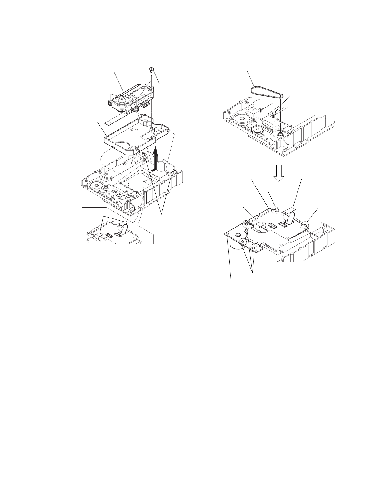
2-3
2-9. OPTICAL PICK-UP REMOVAL 2-10. BELT, LOADING MOTOR (M001),
MS-29/46, TK-51 BOARD REMOVAL
3 Remove the base
unit holder in the
direction of the
arrow A.
2 Two claws
1 Two flexible board
(CN001, 002)
5 Optical pick-up
4 Three step
screws
A
2 Two screws
(B2.6 × 4)
1 Belt
9 TK-51 board
8 Claw
7 Claw
6 Flexible board
(CN001)
5 Flexible board
(CN002)
3 Three claws
4 Loading motor (M001),
MS-29 board (Taiwan)
MS-46 board (EXCEPT Taiwan)
2-4
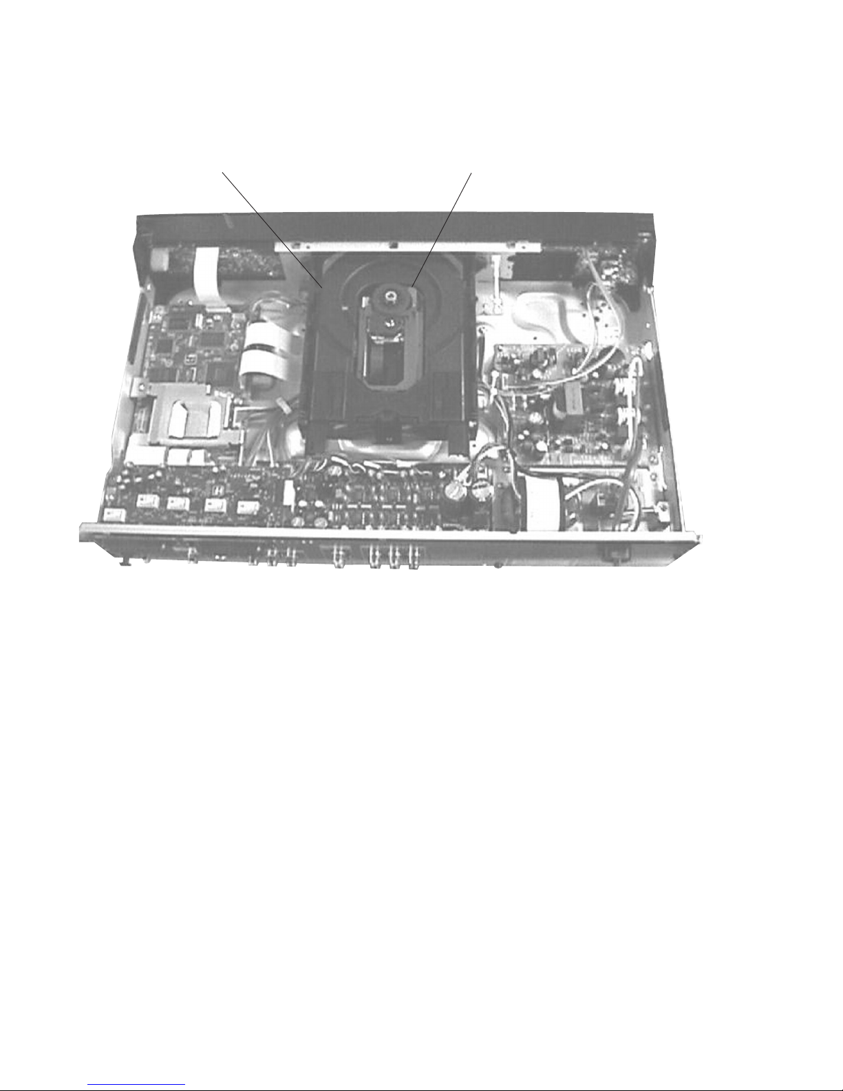
2-11. INTERNAL VIEWS
DC motor (loading)
1-541-632-11
Optical pick-up (KHM-220AAA/J1RP)
8-820-081-03
2-5
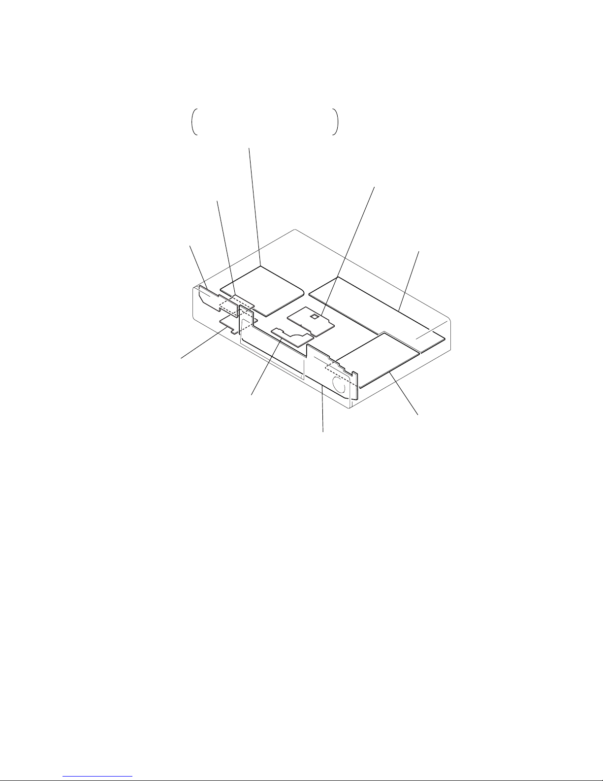
2-12. CIRCUIT BOARDS LOCATION
2-5 E
Power Block
HS-030SH (EXCEPT Taiwan)
HS-030SU (Taiwan)
(SWITCHING REGULATOR)
TK-51
(RF/SERVO)
AU-214
(AUDIO)
MB-82
(SIGNAL PROCESS/SERVO)
FL-103
(FUNCTION SWITCH)
MS-29 (Taiwan)
MS-46 (EXCEPT Taiwan)
(LOADING)
VR-71
(MIC/ECHO LEVEL)
MC-121
(MIC IN/MIC AMP)
FR-153
(IR/POWER SWITCH)
DVP-K330
3-1 3-2
SECTION 3
BLOCK DIAGRAMS
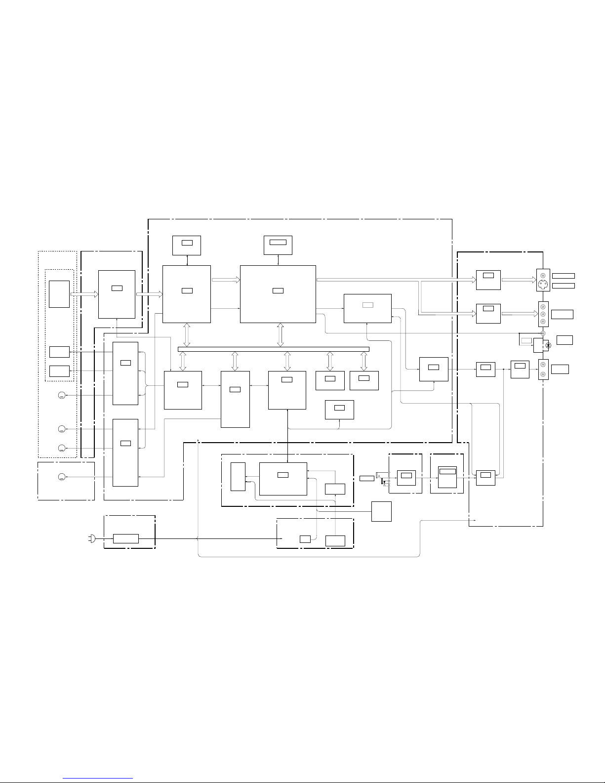
3-1. OVERALL BLOCK DIAGRAM
TK-51 BOARD
(SEE PAGE 4-11)
BASE UNIT
KHM-220AAA
MB-82 BOARD
(SEE PAGE 4-19 to 39)
AU-214 BOARD
(SEE PAGE 4-43)
MC-121 BOARD
(SEE PAGE 4-55)
VR-71 BOARD
(SEE PAGE 4-59)
FL-103 BOARD
(SEE PAGE 4-47, 49)
MS-29/46 BOARD
(SEE PAGE 4-14)
FR-153 BOARD
(SEE PAGE 4-53)
05
DVD RF,
CD RF
DVD/CD
PDIC
OPTICAL DEVICE
SLED
MOTOR
SPINDLE
MOTOR
M
TILT
MOTOR
M
M
M001
LOADING
MOTOR
M
TRACKING
COIL
FOCUS
COIL
IC001
DVD/CD RF AMP
DIGITAL SERVO
IC801
FOCUS COIL/
TRACKING COIL/
TILT MOTOR
DRIVE
IC601
HGA
Serial BUS
CURSOR
UNIT
–12V
EVER5V
+3.3V
+5V
A+12V
M+12V
+3.3V
+5V
+12V
–12V
EVER5V
REG
DC-DC
CONVERTER
IR
ND201
IC201
IF CON
IC701
IC202
IC802
SPINDLE/SLED/
LOADING
MOTOR DRIVE
CDDOUT, CDDATA,
CDBCK, CDLRCK
IC303
ARP2
SD 0-7
RF
IC401
AV DECODER
IC304
16M DRAM
IC402, 403
16M SDRAM
IC204
1M SRAM
IC201
4K EEP ROM
IC205
16FLASH
IC902
AUDIO 2CH DAC
SPDIF
Parallel BUS
VIDEO V,
VIDEO Y,
VIDEO C
VIDEO G/Y,
VIDEO R/B-Y,
VIDEO B/R-Y
ACH12,
BCK, LRCK
IC901
KARAOKE DSP
VIDEO
BUFFER
LPF +6dB
AUDIO LT,
AUDIO RT
VIDEO
BUFFER
VIDEO 1, 2
S VIDEO 1, 2
MIC 1, 2
COMPONENT
VIDEO
DIGITAL
OUT
AUDIO
OUT1, 2
HS-030SH/SU BOARD
(SEE PAGE 4-63)
SW REG
SERVO DSP
SYSTEM CONTROL
SPDIF
IC431
IC321
IC303
MIC/ECHO
BUFFER
IC506
MIC AMP
IC102
MIC VOL,
MIC MIX
AMP
IC804, 806
AUDIO
MIX AMP
IC432
IC505
A IN,
A OUT
VEE
F1,2
DVP-K330
3-3 3-4
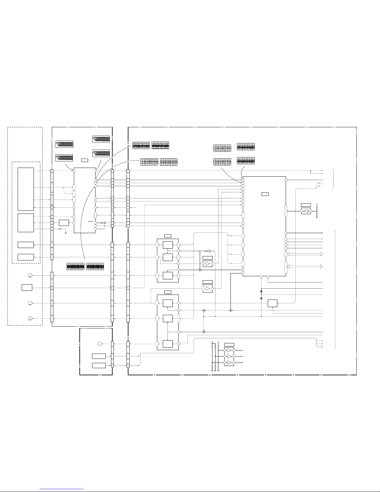
3-2. RF/SERVO BLOCK DIAGRAM
INLIMIT
SENSOR
TK-51 BOARD
(SEE PAGE 4-11)
BASE UNIT
KHM-220AAA
MB-82 BOARD(1/5)
(SEE PAGE 4-23,25)
MS-29/46 BOARD
(SEE PAGE 4-14)
M
2
10
12
16
4
15
CN002CN003
CN001
DVD/CD RF AMP
DIGITAL SERVO
RF+
FE
TE
PI
MIRR
TZC
2VC
2VC
SSDFCT
SSDFCTI
RF
A-D
E-H
VC
PD
LD
VR
FCSFOCUS
COIL
DVD/CD
LD MODULE
DVD/CD
PDIC
OPTICAL DEVICE
TRACKING
COIL
TRK
11
14
13
17
9
7
13
7
3
15
4
8
5
6
CN003
CN011
CN001
LDM
M001
LOADING
MOTOR
M
SLED
MOTOR
M
SPINDLE
MOTOR
M
TILT
MOTOR
OCSW 1, 2
CKSW1
OCSW 1, 2
CKSW1
3
1 54
FE
40
TE
39
PI
MIRR
26
TZC
32
27
HOLD2
42
DFT
31
VCI
33
43
ı
46
9
ı
12
17
19
20
5
ı
8
13
ı
16
Q002
Q801
SSCK, SSWD,
SSRD, SSCS
1
2
4
6
3
1
2
4
6
S001
TRAY SENSOR
S002
CHUCK SENSOR
TRK
TIA, TIB
INLIM
SPM
SLA, SLB
TIA, TIB
INLIM
SPM
SLA, SLB
05
FCS
12
13
14
15
5
6
1
ı
4
7
ı
10
11
CN004
6
7
4
5
13
14
15
ı
18
9
ı
12
8
CN002
19
20
21
22
8
9
10
ı
13
4
ı
7
2
5
2
4
9
10
16
17
8
11
15
18
11
ı
14
5
ı
8
FDCHG
SIGO
A-D
RF IP
A2-D2
E-H
VC
SCLK
SWD
SRD
SDEN
PD
LD
Q001
LD DRIVE
IC001
69
22
41
ı
44
ADC0
68
ADC1
67
ADC2
66
ADC3
65
ADC4
FCSON
XSDPIT
XSDPRD
XSDPWR
XSDPCS
HA0, 1
HD8-15
N27MSDP
XSDPRST
X3VRST
DVD RF
CD RF
MDP0
LOCK
MDS0
SERVO DSP
20
TRREF
21
TRIN
23
FGIN
38
GIO 11
28
DFCTI
128
HINT
39
GIO 10
VRBA,
VRB 0-3
FG REF
1
HRD
2
HWR
3
HCS
EA 0, 1
HD 0-7
46
GIO 4
RS
X2/CLKIN
50
26 108
GIO 0
GIO 5-8
DAB 0, 1
DAB 2,3
GIO 1, 2
PWM 0-2
TRD
TILT MUTE
FGMODE
FCD
TLTA,TLTB
117
ı
120
122
ı
125
74
81
84
93
96
15
ı
18
13
14
2
3
11
12
5
6
23
26
FOCUS
COIL
DRIVE
TILT
MOTOR
DRIVE
Q802, 803
GAIN
CONTROL
TRACKING
COIL
DRIVE
TRD
FCD
TLTA, TLTB
7
9
20
IC801
IC701
IC702 (1/2)
11
ı
14
15
16
17
18
SPINDLE
MOTOR
DRIVE
LOADING
MOTOR
DRIVE
SLED
MOTOR
DRIVE
SLDA, SLDB,
STVC
+3.3V
2.5VC
2VC
1.6VC
+5V
20
26
23
IC802
3 1
IC702 (2/2)
+3.3V
7 5
IC803 (1/2)
IC803 (2/2)
14
12
13
9
2
3
5
6
SLDA, SLDB,
STVC
7
ı
9
80
85
92
97
48
49
4
5
SPDLSTOP
SPGAIN
XDRV MUTE
LDMM/DMM
LDMP/DMP
OCSW1
OCSW2
CKSW1
10
8
3 1
5 7
SYSTEM
CONTROL
(SEE PAGE 3-7,8)
SIGNAL PROCESS,
VIDEO
(SEE PAGE 3-5)
500mV/DIV 100ns/DIV
IC001%¢(DVD play)
880mVp-p
500mV/DIV 500ns/DIV
IC0011(CD play)
IC0011(DVD play)
536mVp-p
200mV/DIV 100ns/DIV
500mV/DIV 500ns/DIV
1.5Vp-p
1.5Vp-p
IC001%¢(CD play)
592mVp-p
200mV/DIV 500ms/DIV
IC001@ª(DVD play)
448mVp-p
200mV/DIV 20ms/DIV
IC001@ª(CD play)
29
500mV/DIV 50ms/DIV
IC001#ª(DVD play)
100mV/DIV 50ms/DIV
180mVp-p
IC001$º(DVD play)
500mV/DIV 50ms/DIV
860mVp-p
1.3Vp-p
IC001$º(CD play)
500mV/DIV 200ms/DIV
IC001#ª(CD play)
1.7Vp-p
500mV/DIV 50ms/DIV
IC701^ª(DVD play)
1.4Vp-p
500mV/DIV 200ms/DIV
IC701^ª(CD play)
1.7Vp-p
100mV/DIV 5ms/DIV
180mVp-p
IC701^•(DVD play)
500mV/DIV 50ms/DIV
860mVp-p
IC701^•(CD play)
DVP-K330
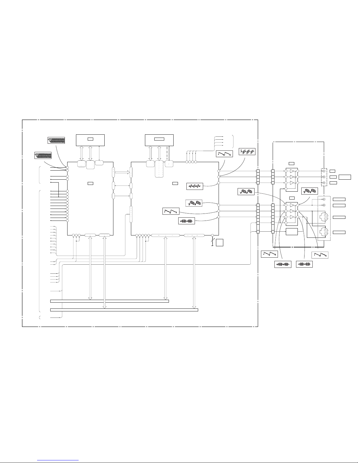
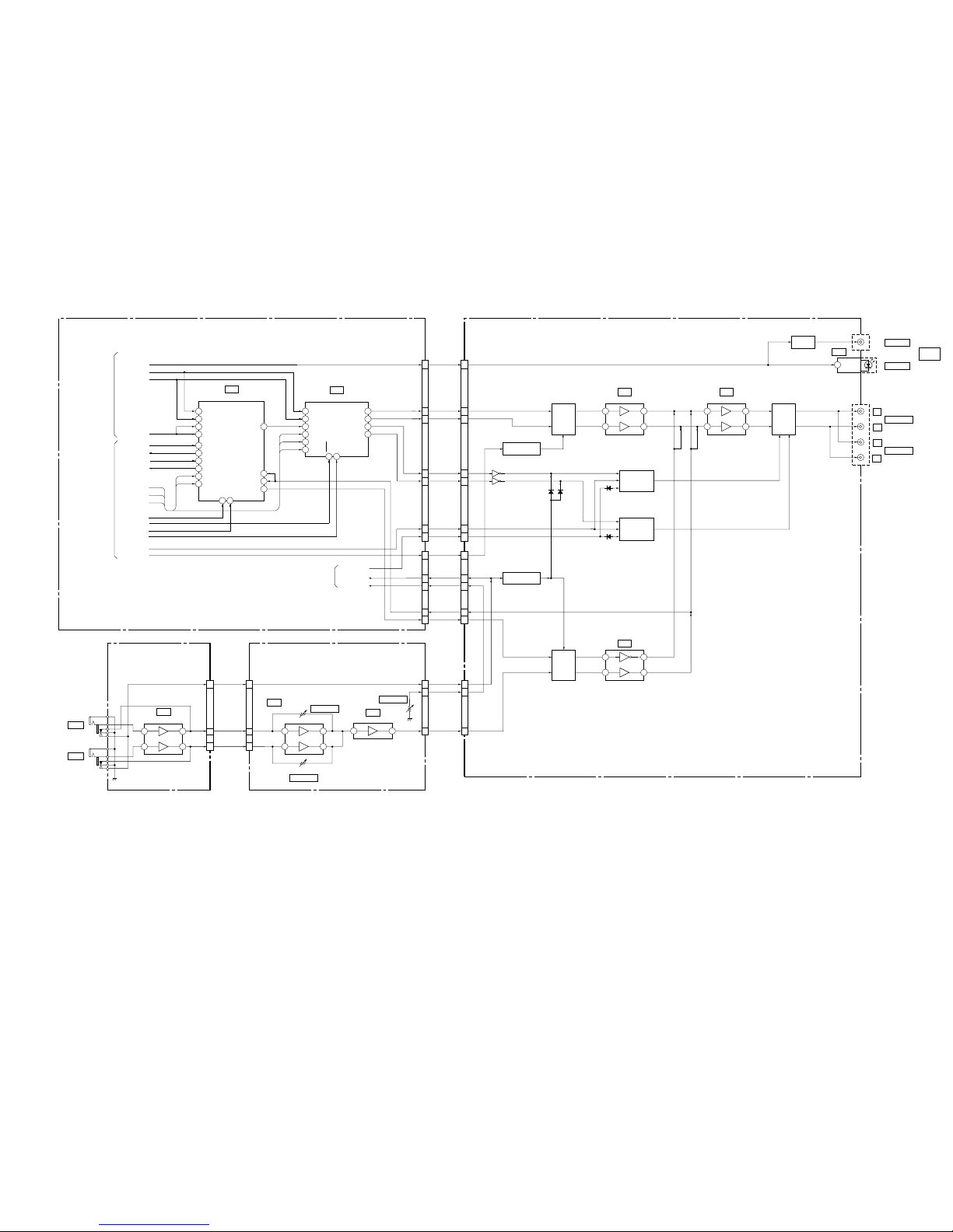
3-3. SIGNAL PROCESS/VIDEO BLOCK DIAGRAM
3-5 3-6
MB-82 BOARD(2/5)
(SEE PAGE 4-19,21,27)
AU-214 BOARD(1/2)
(SEE PAGE 4-43)
1
1
54
57
65
61
62
58
IC304
16M DRAM
IC303
ARP2
IC401
AV DECODER
CB/B-Y
CR/R-Y
VIDEO OUT1
VIDEO OUT2
S VIDEO OUT1
S VIDEO OUT2
Y
IC303
VIDEO BUFFER
IC321
VIDEO BUFFER
J505
55
56
58
59
DFCT
NORF
49
52
MDS0
MDP0
17
19
RFIN1
RFIN2
MDS0
MDP0
DVD RF
CD RF
LOCK
FWON
113
121
123
111
60
61
MD2
MUTE
XWR
XRD
83
84
86
XINT
XCS
XWAT
DFCT
NORF
LOCK
FWON
MD2
MUTE
XARPWR
XARPRD
XARPIT
XARPCS
XARPWT
XCS2
XCS3
XRD
XWRH
XAVDIT
XAVDWT
DACK0
DREQ0
DACK1
DREQ1
XARPRST
XAVDRST
33MARP
256FS30
33M30
27M30
VS
V MUTE
05
HD 0-15
HA 0-21
87
SCKI
MD 00-15
MA 0-9
XMWR, XCAS,
XRAS, XOE
XARPRST
33MARP
HA 0-7
HD 8-15
A 0-7
D 0-7
MCKI
XRST
103 19 36
CRPCLKI
ACLKI
SCLKIN
HAD 0-21 I
HD 0-15
CLKI
RSTIN
256FS30
XAVDRST
27M30
33M30
160 163
VREFI
70
73-76 79-82
154-157
159-162
164-167
169-172
136-139
141-144
146 147
134 135
137 138
140 141
143 144
146 147
149 150
152 153
155 156
105-108
110-113
115-118
120-123
125 127
129-132
148
150-152
63-68 70 71
HA 0-21
HD 0-15
IC402, 403
16M SDRAM
DDT 0-15
DAD 0-11
107
ı
110
29
ı
32
47
ı
51
91
93
ı
96
97
98
100
ı
105
SD 0-7
SD 0-7
DT 0-7 I
SDCK, SDEF,
XSHD, XSAK, XSRQ
CDDOUT, CDDATA,
CDBCK, CDLRCK
38
ı
43
45
46
166
167
193
194
196
198
ı
202
168-170 172-178 180-187 189-192 2-5 7-10 12-15 205-208
21
ACH12
LRCK
BCK
SPDIF1
ACH12
LRCK
BCK
SPDIF1
ACH12O
G/Y OUT
R/B-Y OUT
B/R-Y OUT
COMP OUT
Y OUT
C OUT
25 26 27
LRCKO
BCKO
DO
LOCK
CLK, CKE,
DQML, DQMU,
CS, WE, CAS, RAS
VIDEO
LEVEL
ADJ
RV401
SYSTEM
CONTROL
(SEE PAGE 3-7,8)
INTERFACE
CONTROL
(SEE PAGE 3-12)
RF, SERVO
(SEE PAGE 3-4)
AUDIO
(SEE PAGE 3-9)
4
CN005
CN004
2
6
1
3
5
8
6
4
VIDEO V
VIDEO Y
VIDEO C
V MUTE
VS
CN303
J303
CN301
VIDEO G/Y
VIDEO R/B-Y
VIDEO B/R-Y
6
2
28
26
24
21
23
4
13
7 10
2 15
2
15
7 10
4 13
COMPONENT
VIDEO OUT
C
Y
C
Y
DC ON/OFF
Q321, 322
500mV/DIV 100ns/DIV
1.6Vp-p
IC303!¶(DVD play)
500mV/DIV 200ns/DIV
1.6Vp-p
IC303!ª(CD play)
1.0Vp-p(H)
IC401%•
720mVp-p(H)
IC401%¢
1.1Vp-p(H)
IC401^¡
816mVp-p(H)
IC401^™
728mVp-p(H)
IC401%
1.2Vp-p(H)
IC401^∞
1.1Vp-p(H)
IC3212
1.2Vp-p(H)
IC3214
860mVp-p(H)
IC3217
2.4 Vp-p(H)
IC321!£
1.8mVp-p(H)
IC3210
2.0Vp-p(H)
IC321!∞
DVP-K330
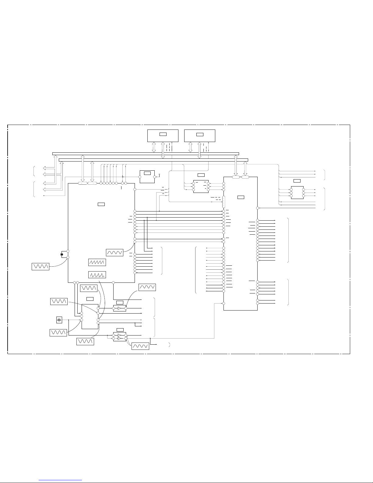
3-7 3-8
3-4. SYSTEM CONTROL BLOCK DIAGRAM
MB-82 BOARD(3/5)
(SEE PAGE 4-29,31,33)
23
XECS
24
XEWC
25
XEBSY
HGA
IC601
BUFFER
IC203
4K EEPROM
IC201
SYSTEM CONTROL
IC202
141
142
145
144
143
157
156
155
114
115
116
117
118
135
102
103
104
105
106
107
108
109
110
111
XINT1
XINT3
3
98
99
CPUCK
10
7
22
23
CS1
11
CS0
CS4
SC0
SO0
SI0
24
19
94
88
RDY
INT1
INT3
83
CLK
MUTE
MD2
NORF
DFCT
FWON
LOCK
VS
SI0
HD 0-15
HA 0-21
SIO
SO0
SC0
SI1
SO1
SC1
XFRRST
CS0L
HA 1-16
HD 0-15
D 16-31
A 00-21
HD 8-15
XIFINT
HA 0-5, 17-19
HD 0-7
HA 0-5, 17-19
SO0
SC0
SI1
SO1
INT2
PB1
MUTE
MD2
NORF
DFCT
FWON
LOCK
72
71
VS
53
59
XRD
XWRH
XCS2
XCS3
XAVDIT
9
8
95
84
85
86
INT0
DACK1
DACK0
DREQ1
87
DREQ0
DACK1
DACK0
DREQ1
DREQ0
MCK
XDACS0
P66
PB4
CKSEL
DVD/CD
PB2
27M30
N27MSDP
X001
27MHz
384FSDA
33M30
256FS30
33MARP
4
112
113
124
125
76 77 78 79 80 89 14 97
X1
X201
12.5MHz
X0
HD 8-15
HA 0, 1
HD 0-15
HA 0-21
X3VRST
91
92
42 44-64
25-39 41
19
66 100 98
1
6
12
14
17
1 7
6 2
1 7
4 3
5 8
6 1
122211
4 6
1 3
FCSON
XSDPRST
XSDPIT
XSDPWR
XSDPRD
XSDPCS
SPDLSTOP
54
57
SPGAIN
XDRVMUTE
XVIFCS
IFSC0
IFSO0
4A
2A
1A
4Y
2Y
1Y
SC1
SO1
SI1
SC1
SO1
SI1
CS0L
SC0
SO0
SI0
XFRRST
IFSI0
XFRRST
XIFINT
LDMP/DMP
LDMM/DMM
OCSW1
OCSW2
CKSW1
FCSON
SPDLSTOP
SPGAIN
XDRVMUTE
LDMP/DMP
LDMM/DMM
OCSW1
OCSW2
CKSW1
94
93
92
91
64
63
88
XDACRST
26
KARAOKE
KARDY
XKARLT
XKRRST
MA MUTE
95
33
KARAOKEON
KARDY
MA MUTE
34
32
49
126-133146-154
PLL
IC001
IC003
IC004
N27MHGA
RF, SERVO
(SEE PAGE 3-4)
SIGNAL PROCESS,
VIDEO
(SEE PAGE 3-5)
MIC MUTE
MIC MUTE
50
RST
CS2
CS3
CE
CS
WE1
RD
WR0
WR1
PF7
MD
ML
XT1
05
SCKO2
SCKO1
768FS25
SCKO4
SCKO3
16M FLASH
IC205
1M SRAM
IC204
CS, WE2,
OE, UB, LB
WE2, UB, LB,
RY/BY, OE
HA 1-20
HD 0-15
WE1, RY/BY,
OE, CE
DI
DO
SK
WC
CS
R/B
4 5
CS1
CS4
HRD
HWRH
HWRL
WAIT
RST
ARPRST
ARPINT
ARPWT
ARPWR
ARPRD
ARPCS
AVDWT
AVDRST
XARPRST
XARPIT
XARPWT
XARPWR
XARPRD
XARPCS
XAVDWT
XAVDRST
DACRST
KARLT
KRRST
SDPRST
SDPIT
SDSPWR
SDSPRD
SDPCS
INTERFACE
CONTROL
(SEE PAGE 3-12)
RF, SERVO
(SEE PAGE 3-4)
RF, SERVO
(SEE PAGE 3-4)
AUDIO
(SEE PAGE 3-9)
AUDIO
(SEE PAGE 3-9)
AUDIO
(SEE PAGE 3-9)
SIGNAL PROCESS,
VIDEO
(SEE PAGE 3-5)
SIGNAL PROCESS,
VIDEO
(SEE PAGE 3-5)
SIGNAL PROCESS,
VIDEO
(SEE PAGE 3-5)
POWER ON
RESET
IC207
+3.3V
2.4Vp-p(12.5MHz)
IC202(™
13
5
DVD:6.2Vp-p(37.0MHz)
CD:5Vp-p(33.6MHz)
IC0037
4.2Vp-p(26.9MHz)
IC0042,7
4.2Vp-p(27.0MHz)
IC0016
DVD:5.6Vp-p(36.8MHz)
CD:5.2Vp-p(33.9MHz)
IC001!£
4.6Vp-p(33.8MHz)
IC001!™
DVD:5.8Vp-p(36.5MHz)
CD:5.1Vp-p(33.8MHz)
IC001!
4.2Vp-p(25.3MHz)
IC001!¢(DVD play)
4.7Vp-p(22.5MHz)
IC001!¢(CD play)
4Vp-p(25.3MHz)
IC2025
DVP-K330
3-9 3-10
3-5. AUDIO BLOCK DIAGRAM
MB-82 BOARD(4/5)
(SEE PAGE 4-35, 37)
MC-121 BOARD
(SEE PAGE 4-55)
VR-71 BOARD
(SEE PAGE 4-59)
AU-214 BOARD(2/2)
(SEE PAGE 4-43)
15
11
13
10
19
LPF +6dB
5
7
3 1
14
18
16
19
10
5
1
Q435, 436
MUTE
Q439, 440
MUTE
Q302, 444, 447
MUTE CONTROL
Q303, 443, 448
MUTE CONTROL
Q446
Q445
Q301, 437
MUTE CONTROL
DIGITAL
OUT
Q341
BUFFER
D IN
IC431
AUDIO MIX AMP
5
7
3 1
IC432
IC505
J505
J502
L
AUDIO OUT1
OPTICAL
COAXIAL
R
L
AUDIO OUT2
MIC 1
MIC 2
R
CN005
CN301
CN008
CN403
CN842
CN402
CN101
CN841
05
MA MUTE
A MUTE
SPDIF
AUDIOLT
AUDIORT
ZFLT
ZFRT
MIC MUTE
MIC MUTE
INTERFACE
CONTROL
(SEE PAGE 3-12)
SYSTEM CONTROL
(SEE PAGE 3-7, 8)
Q438, 442
MUTE CONTROL
14
2
3
1
6 7
2
2
Q441, 443
MUTE
IC506
MIC AMP
3
5
1
7
IC102
2
1
6 7
MIC VOL AMP
IC841
MIC MIX AMP
6
7
IC806
MIC1 IN
MIC1 IN
FMIC1
15 1
6 6
5 5
ECHO CONT
ECHO CONT
3 4
1 6
6 1
5
3
11
13
ECHO AD
ECHO DAP
MIC1 IN
ECHO CONT
MIC1
MIC1 IN
FMIC2
7 22
MA MUTE
9 20
A MUTE
11
J101
J102
MIC 2 LEVEL
MIC 1 LEVEL
RV802
RV801
ECHO LEVEL
RV803
SIGNAL PROCESS,
VIDEO
(SEE PAGE 3-6)
99
98
90 86
91
21
29
3
1
2
95
2
5
4
3
1
8 37
26
16
13
21
17
27
28
522
IC902
AUDIO 2CH DAC
V OUT L
V OUT R
ZERO
ZEROR
BCLKIN
LRCIN
D IN
MD
MC
ML
SO1
SC1
CS0
XTI
RSTB
XTLI
XRST
SO1
SC1
SO1
SC1
CS0
SO1
SC1
XDACS0
SPDIF1
BCK
LRCK
ACH12
KARAOKE
KRDY
XKARLT
SI1
KROK
REDY
RVDT
TRDT
SCK
LRCKI
BCKI
SI
SI78
SO78
20
A IN3
A OUT
XKRRST
XDACRST
768FS25
384FSDA
XLAT
IC901
KARAOKE DSP
L03
 Loading...