

Sony DVP-S500D, RMT-D102, DVP-S505D, RMT-D102E Service Manual
MICROFILM
SERVICE MANUAL
US Model
DVP-S500D
Canadian Model
DVP-S500D
E Model
DVP-S500D
Hong Kong Model
DVP-S505D
Singapore Model
DVP-S505D
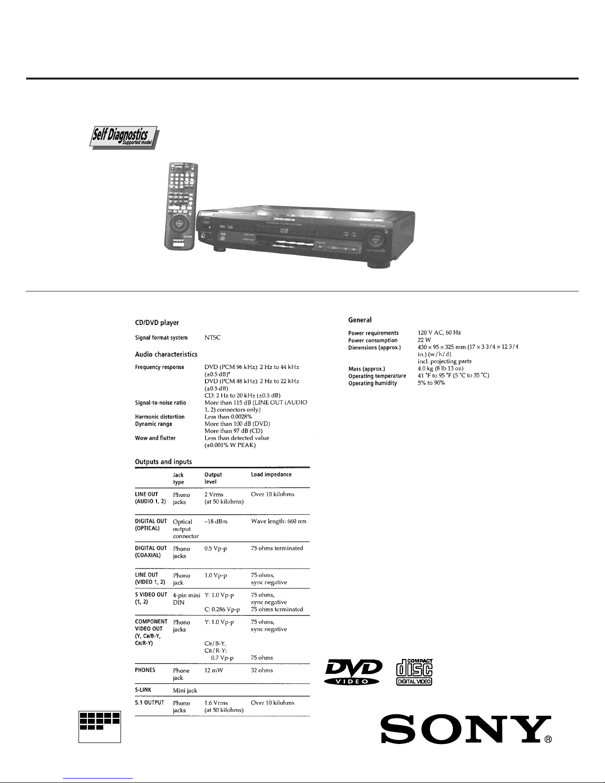
CD/DVD PLAYER
DVP-S500D/S505D
RMT-D102A/D102E
SPECIFICATIONS
• Audio/video/S-link connecting cord (1) (S500D: US, Canadian)
• Audio/Video connecting cord (1)
(S500D: E/S505D)
• S video cable (1)
• Remote commander (remote) RMT-D102A (1) (S500D)
• Remote commander (remote) RMT-D102E (S505D)
• Sony R6 (size AA) batteries (2)
Design and specifications are subject to change without notice.
– 2 –
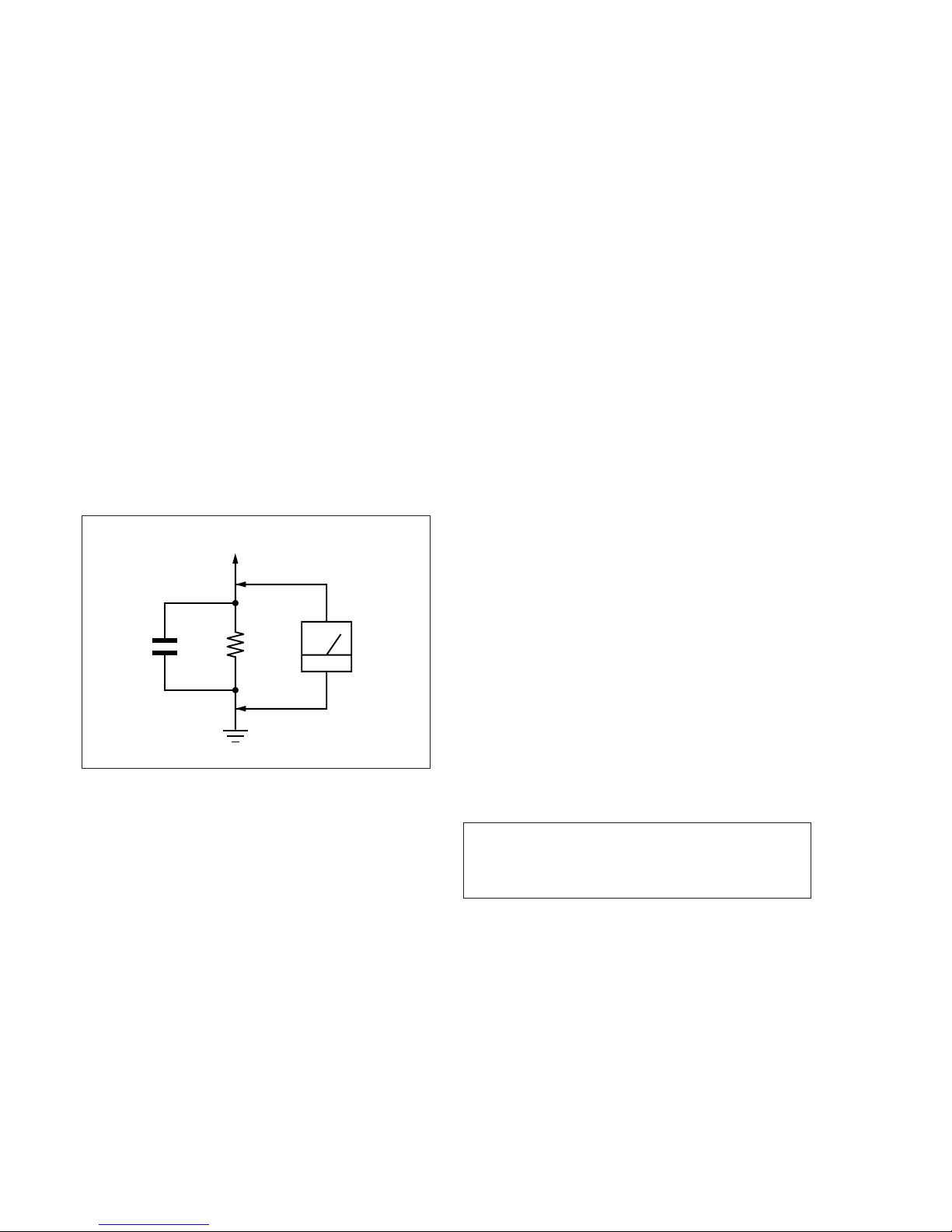
LEAKAGE TEST
The AC leakage from any exposed metal part to earth ground
and from all exposed metal parts to any exposed metal part having
a return to chassis, must not exceed 0.5 mA (500 microamperes).
Leakage current can be measured by any one of three methods.
1. A commercial leakage tester, such as the Simpson 229 or RCA
WT -540A. Follow the manufacturers' instructions to use these
instruments.
2. A battery-operated A C milliammeter. The Data Precision 245
digital multimeter is suitable for this job.
3. Measuring the voltage drop across a resistor by means of a
VOM or battery-operated AC voltmeter. The “limit” indica-
tion is 0.75V, so analog meters must have an accurate low-
voltage scale. The Simpson 250 and Sanwa SH-63T rd are ex-
amples of a passive VOM that is suitable. Nearly all battery
operated digital multimeters that have a 2V A C range are suit-
able. (See Fig. A)
Fig. A Using AC voltmeter to check AC leakage
1.5 k
Ω
0.15 µF
AC
Voltmeter
(0.75 V)
To Exposed Metal
Parts on Set
Earth Ground
WARNING!!
WHEN SERVICING, DO NO T APPR O A CH THE LASER
EXIT WITH THE EYE TOO CLOSELY. IN CASE IT IS
NECESSARY TO CONFIRM LASER BEAM EMISSION,
BE SURE TO OBSERVE FROM A DISTANCE OF
MORE THAN 25 cm FROM THE SURFACE OF THE
OBJECTIVE LENS ON THE OPTICAL PICK-UP BLOCK.
CAUTION:
The use of optical instrument with this product will increase eye
hazard.
ATTENTION AU COMPOSANT AYANT RAPPORT
À LA SÉCURITÉ!
LES COMPOSANTS IDENTIFIÉS P AR UNE MARQUE !
SUR LES DIAGRAMMES SCHÉMATIQUES ET LA LISTE
DES PIÈCES SONT CRITIQUES POUR LA SÉCURITÉ
DE FONCTIONNEMENT. NE REMPLACER CES COMPOSANTS QUE PAR DES PIÈCES SONY DONT LES
NUMÉROS SONT DONNÉS DANS CE MANUEL OU
DANS LES SUPPLÉMENTS PUBLIÉS PAR SONY.
1. Check the area of your repair for unsoldered or poorly-soldered connections. Check the entire board surface for solder
splashes and bridges.
2. Check the interboard wiring to ensure that no wires are
“pinched” or contact high-wattage resistors.
3. Look for unauthorized replacement parts, particularly transistors, that were installed during a previous repair. Point them
out to the customer and recommend their replacement.
4. Look for parts which, though functioning, show obvious signs
of deterioration. Point them out to the customer and recommend their replacement.
5. Check the B+ voltage to see it is at the values specified.
6. Check the B+ voltage to see it is at the values specified.
7. Check the antenna terminals, metal trim, “metallized” knobs,
screws, and all other exposed metal parts for AC leakage.
Check leakage as described below.
SAFETY CHECK-OUT
After correcting the original service problem, perform the following
safety checks before releasing the set to the customer:
SAFETY-RELATED COMPONENT WARNING!!
COMPONENTS IDENTIFIED BY MARK ! OR DOTTED
LINE WITH MARK ! ON THE SCHEMATIC DIAGRAMS
AND IN THE PARTS LIST ARE CRITICAL TO SAFE
OPERATION. REPLACE THESE COMPONENTS WITH
SONY PARTS WHOSE PART NUMBERS APPEAR AS
SHOWN IN THIS MANUAL OR IN SUPPLEMENTS PUBLISHED BY SONY.
CAUTION
Use of controls or adjustments or performance of procedures
other than those specified herein may result in hazardous radiation exposure.

– 3 –
TABLE OF CONTENTS
Section Title Page Section Title Page
Service Note ............................................................................ 4
1. GENERAL
This Player Can Play the Following Discs .................... 1-1
Getting Started .............................................................. 1-1
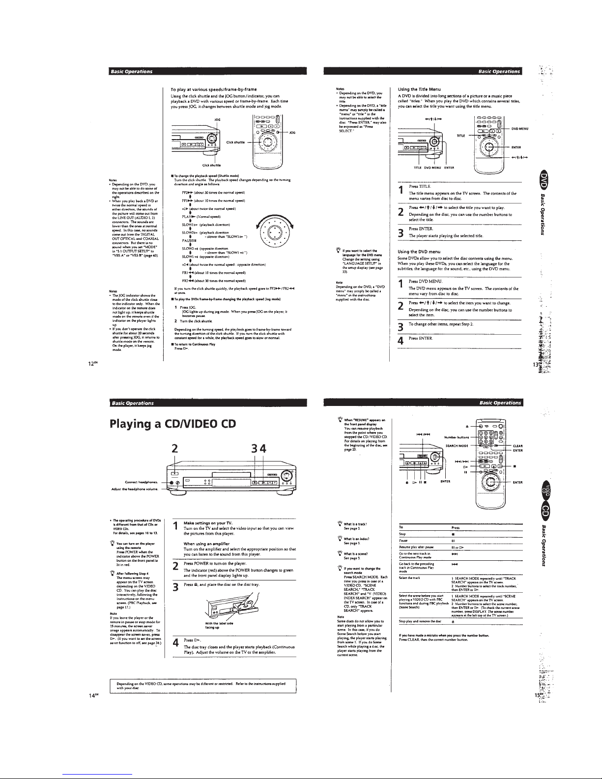
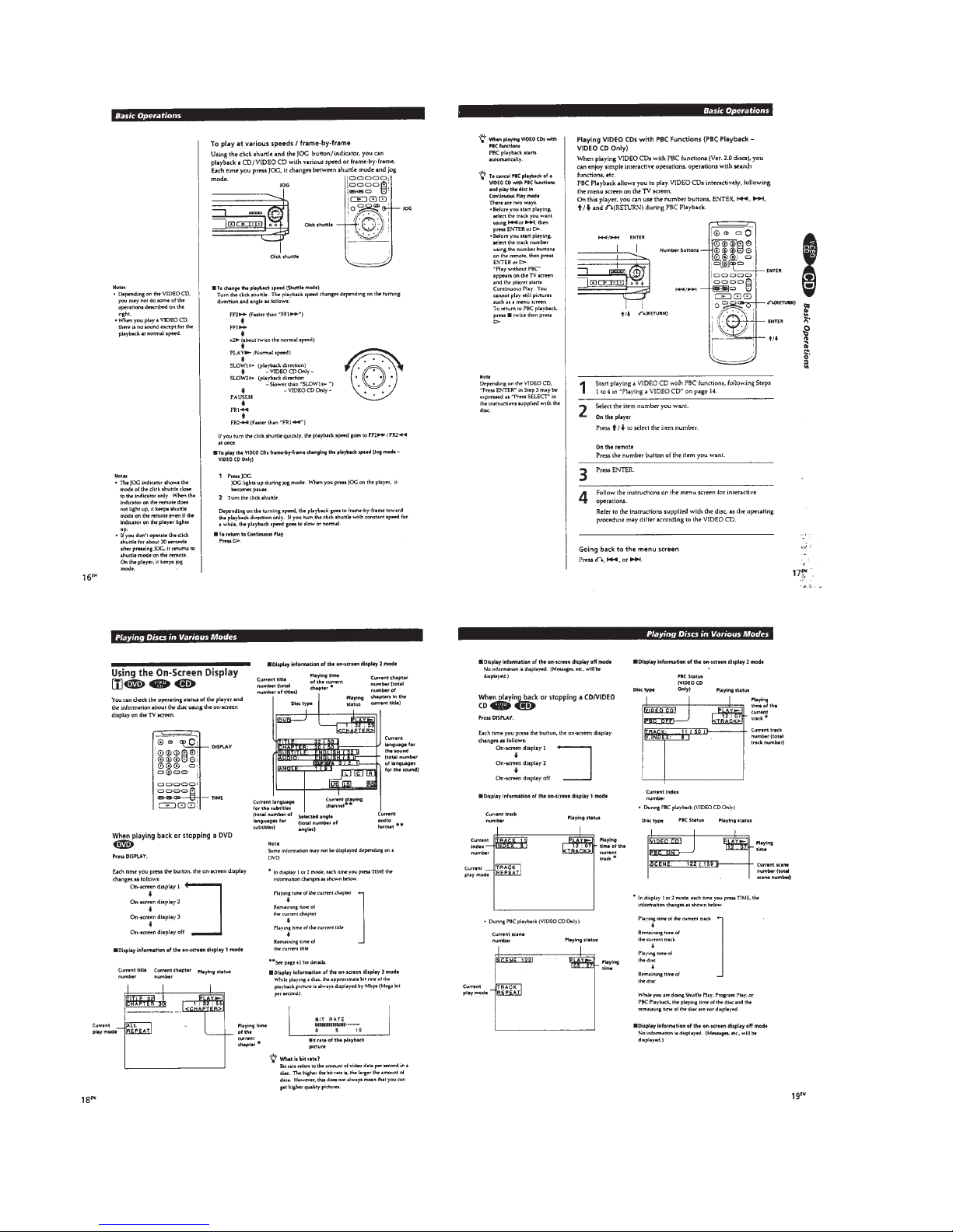
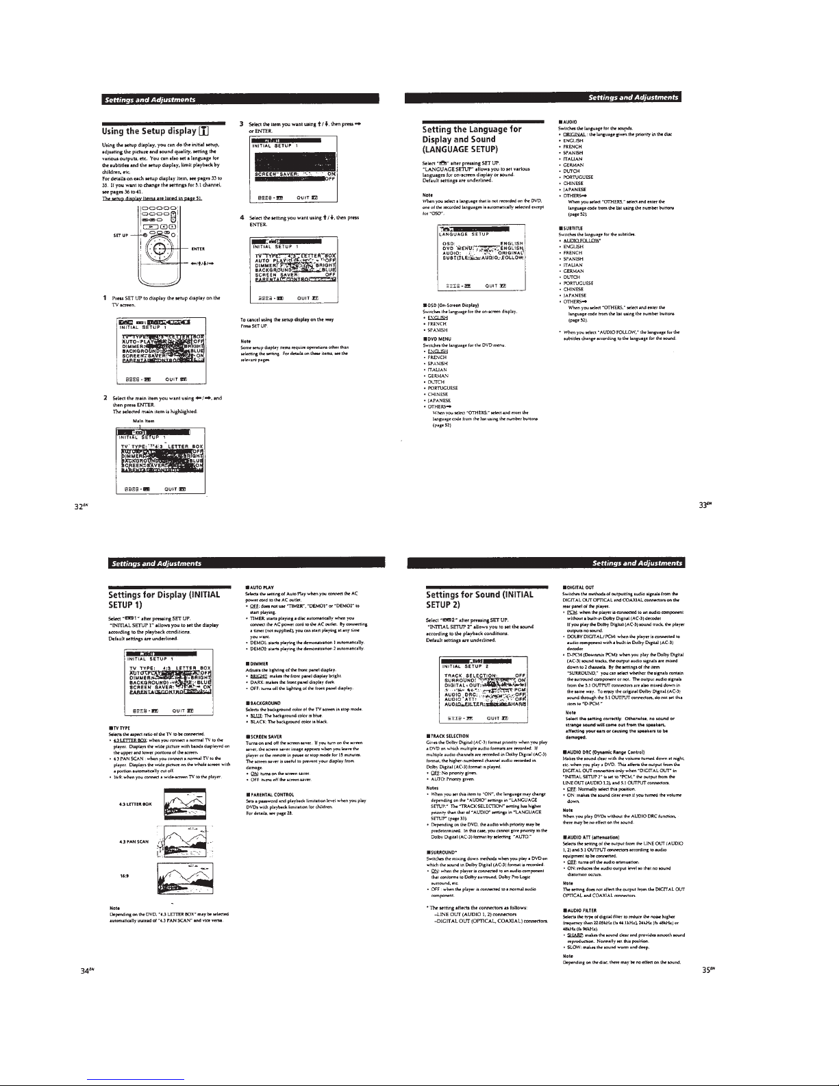
Basic Operations ........................................................... 1-2
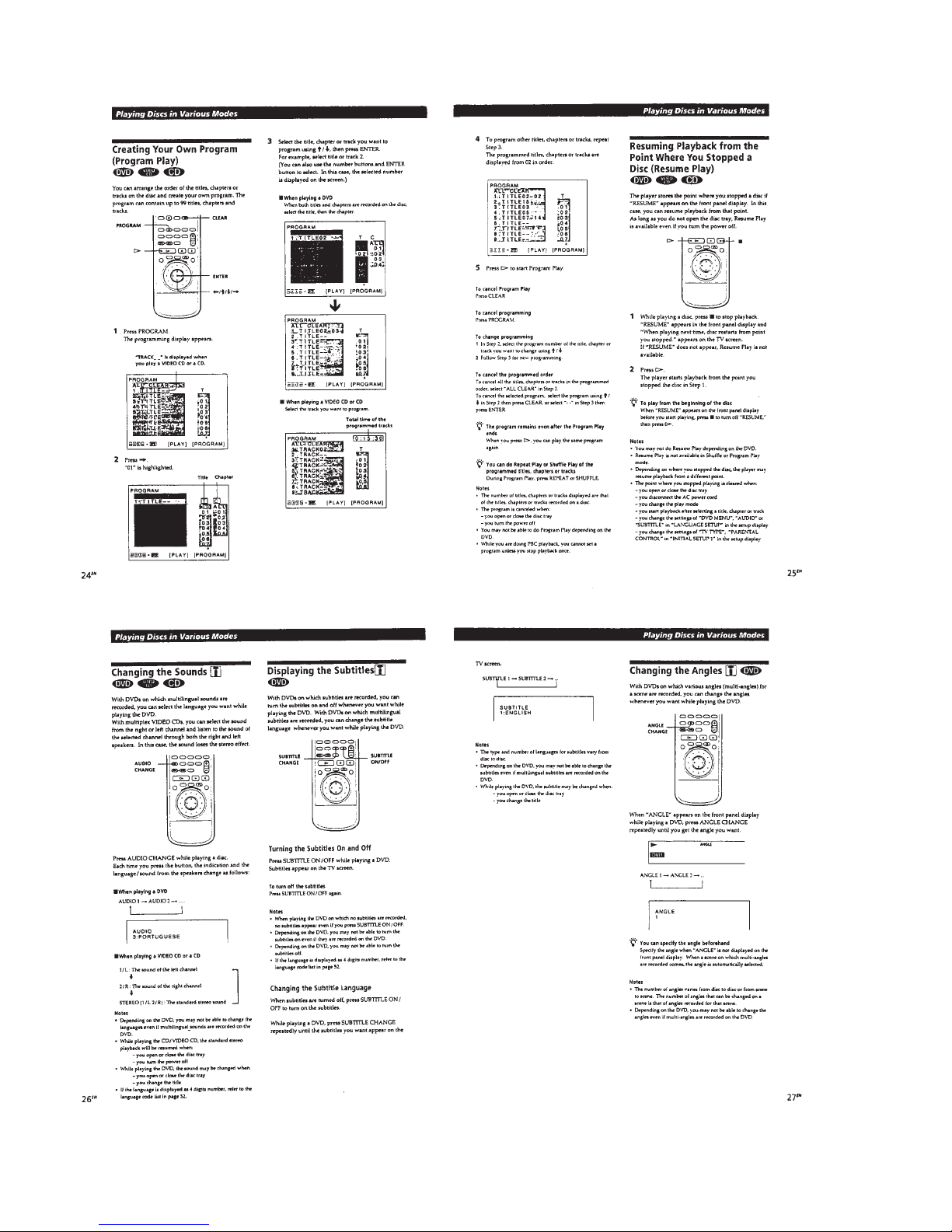
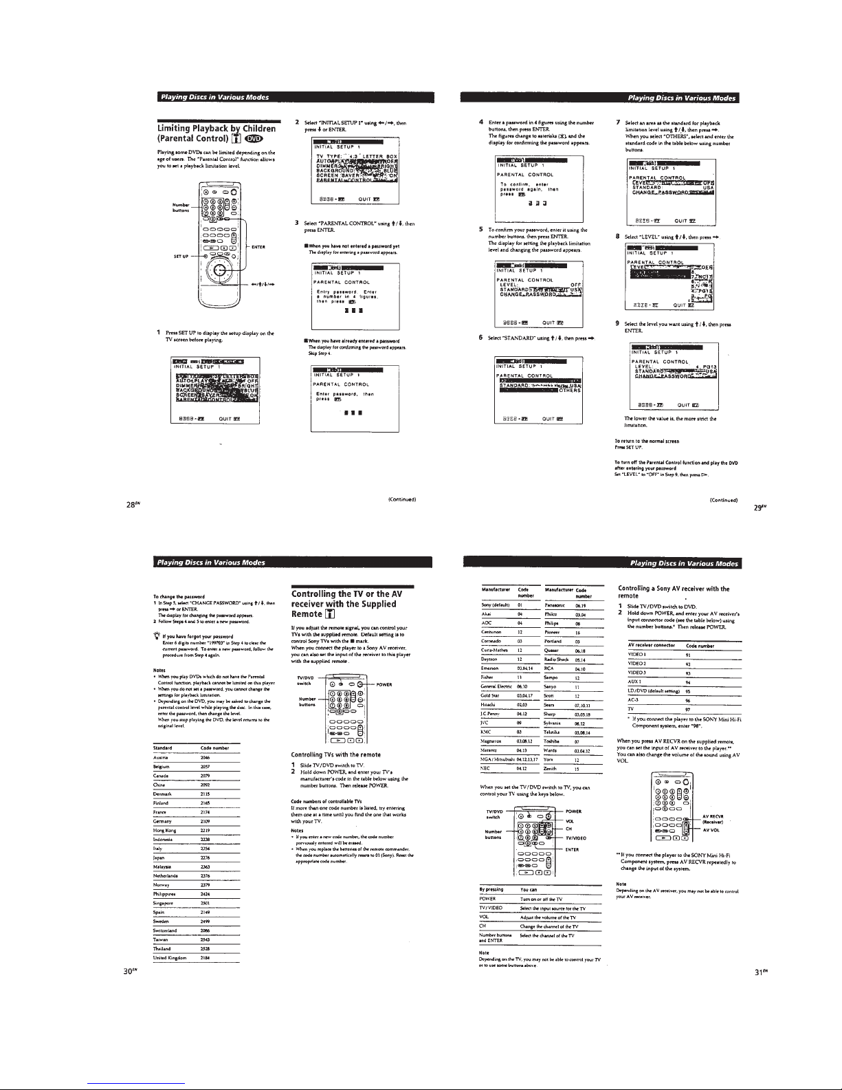
Playing Discs in Various Modes .................................... 1-4
Setting and Adjustments ............................................... 1-8
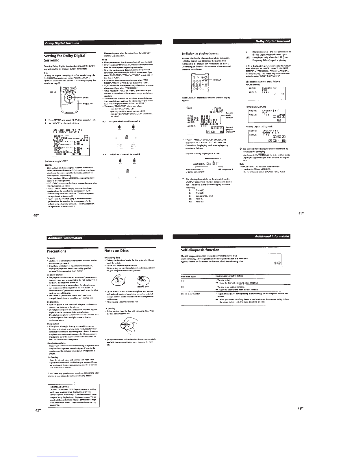
Dolby Digital Surround .................................................. 1-9
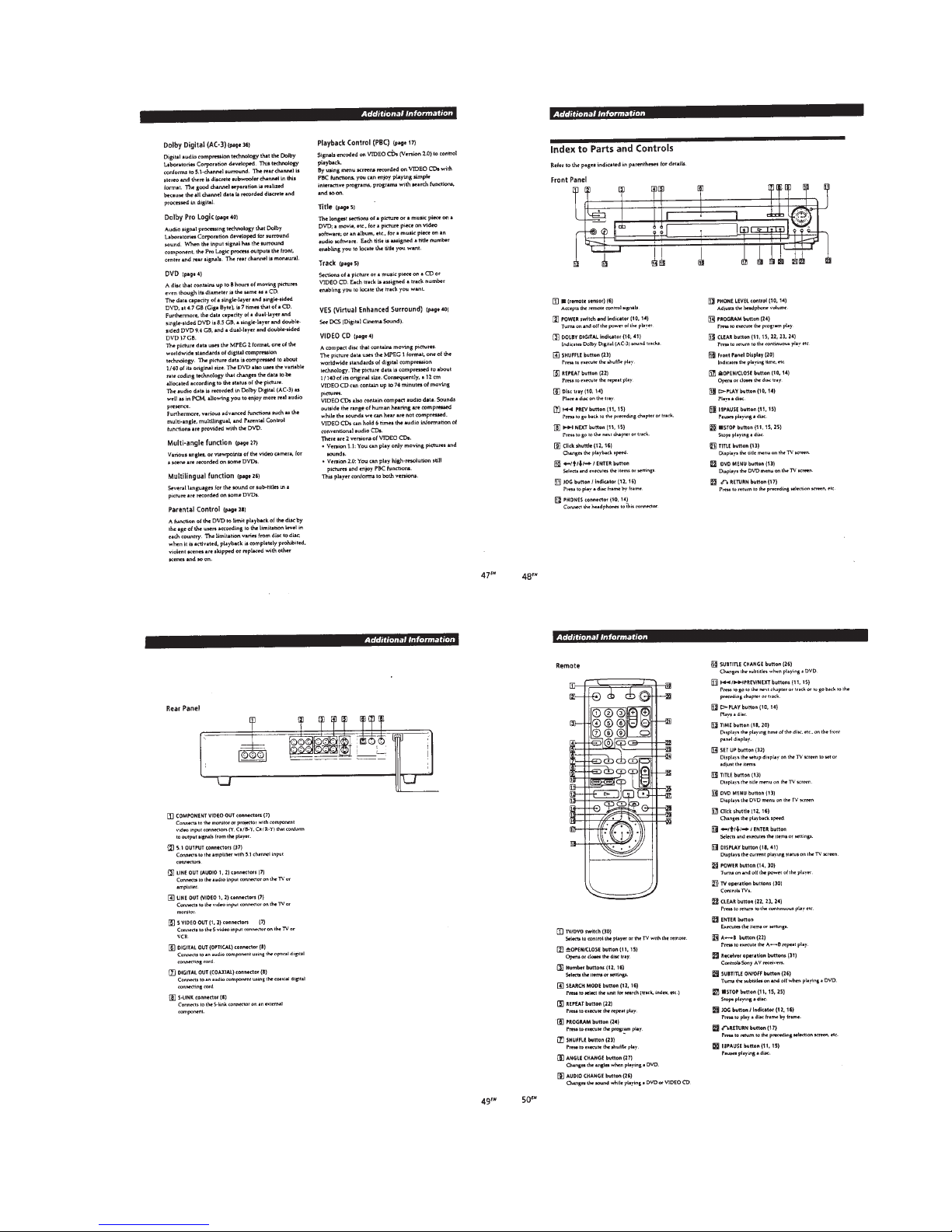
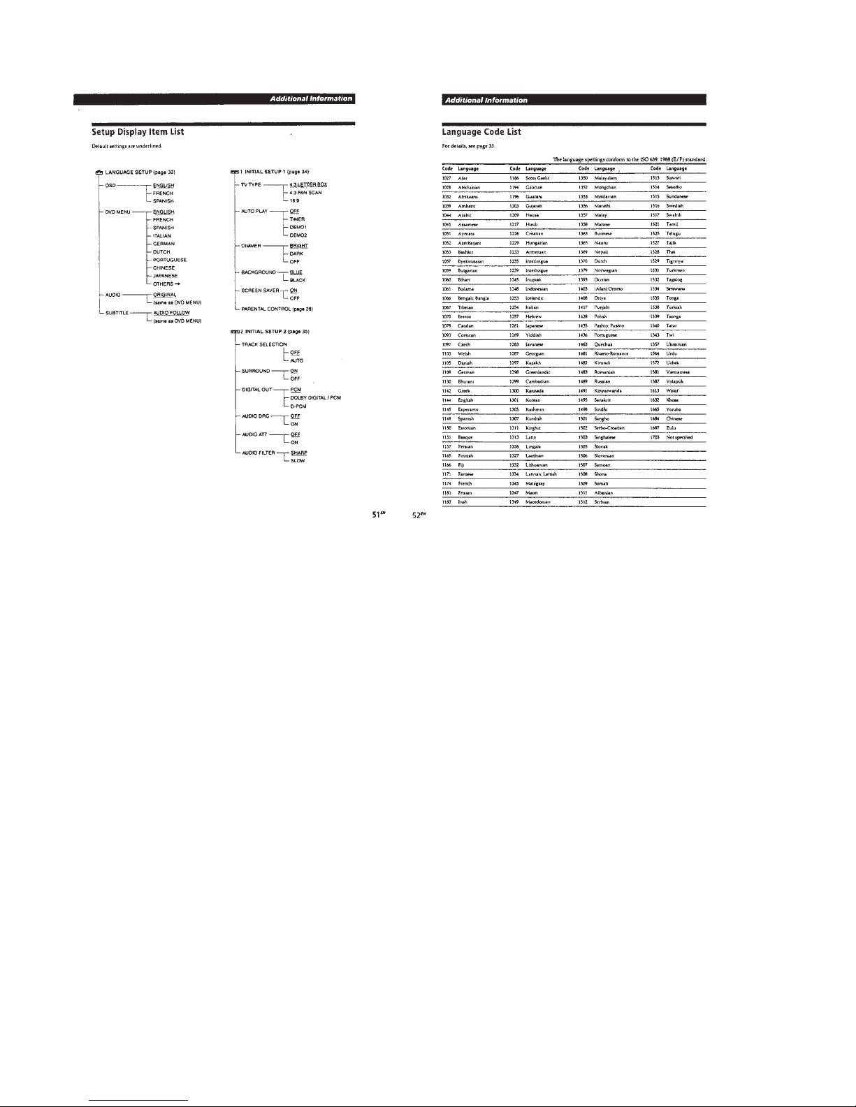
Additional Information ................................................... 1-10
2. DISASSEMBLY
2-1. Case Removal ............................................................... 2-1
2-2. Front Panel Section Removal ....................................... 2-1
2-3. MB-78 Board Removal .................................................. 2-1
2-4. AU-197 Board Removal ................................................ 2-1
2-5. MD Block Ass’y Removal .............................................. 2-2
2-6. TK-47 Board Removal................................................... 2-2
2-7. Tray Removal ................................................................. 2-2
2-8. Skew Motor (M902) Removal........................................ 2-2
2-9. Sled Motor (M501) Removal ......................................... 2-3
2-10. Spindle Motor (M901) Removal .................................... 2-3
2-11. Optical Pick-up Removal ............................................... 2-3
2-12. Internal Views ................................................................ 2-4
2-13. Circuit Boards ................................................................ 2-5
3. BLOCK DIAGRAMS
3-1. Block Diagram 1 (RF, Servo, Power)............................. 3-1
3-2. Block Diagram 2 (Signal Process) ................................ 3-6
4. PRINTED WIRING BOARDS AND SCHEMATIC
DIAGRAMS
4-1. Frame Schematic Diagram............................................ 4-1
4-2. Printed Wiring Boards and Schematic Diagrams ......... 4-5
TK-47 Printed Wiring Board .......................................... 4-5
TK-47 Schematic Diagram ............................................ 4-7
MB-78 Printed Wiring Board ......................................... 4-12
MB-78 (AV Decoder) Schematic Diagram .................... 4-17
MB-78 (Video Encoder) Schematic Diagram................ 4-21
MB-78 (Drive), FG-43 Schematic Diagrams................. 4-25
MB-78 (DSP) Schematic Diagram ................................ 4-30
MB-78 (BIAS) Schematic Diagram ............................... 4-33
MB-78 (IF µ-com) Schematic Diagram ......................... 4-37
MB-78 (ARP, L Gate Array, Decrypt)
Schematic Diagram ....................................................... 4-41
MB-78 (System µ-com, S Gate Array)
Schematic Diagram....................................................... 4-45
MB-78 (AC3 Decoder) Schematic Diagram.................. 4-49
AU-197 Printed Wiring Board........................................ 4-53
AU-197 Schematic Diagram ......................................... 4-57
FL-88, FR-133, LE-19 Printed Wiring Boards .............. 4-61
FL-88, FR-133, LE-19 Schematic Diagrams ................ 4-65
YS-14, HP-96 Printed Wiring Boards and
Schematic Diagrams ..................................................... 4-69
POWER BLOCK (HS-930SF) Printed Wiring Board
and Schematic Diagram................................................ 4-73
POWER BLOCK (HS-930SU) Printed Wiring Board
and Schematic Diagram................................................ 4-76
5. IC PIN FUNCTION DESCRIPTION
5-1. Interface Control Pin Function (MB-78 Board IC604) .. 5-1
5-2 System Control Pin Function (MB-78 Board IC805) .... 5-2
6. TEST MODE
6-1. Starting up Test Mode ................................................... 6-1
6-2. Selection of Check Item ................................................ 6-1
6-3. Error Display.................................................................. 6-2
6-4. General Description of Checking Method..................... 6-2
6-5. Drive Auto Adjustment................................................... 6-10
6-6. Drive Manual Operation ................................................ 6-14
6-6-1. Drive Manual Operation menu screen..................... 6-14
6-6-2. Disc Type .................................................................. 6-14
6-6-3. Manual Control 1...................................................... 6-14
6-6-4. Manual Control 2...................................................... 6-15
6-6-5. Manual Control 3...................................................... 6-15
6-6-6. Manual Adjust 1........................................................ 6-15
6-6-7. Manual Adjust 2........................................................ 6-16
6-6-8. Auto Adjust ............................................................... 6-16
6-6-9. Check ....................................................................... 6-16
6-6-10. EEPROM Data screen Display ................................ 6-17
6-7. Other Operation............................................................. 6-18
7. ELECTRICAL ADJUSTMENT
7-1. Power Supply Check ..................................................... 7-1
1. HS-930SF/930SU Board............................................... 7-1
7-2. Adjustment of System Control ...................................... 7-2
1. 27 MHz Free Run .......................................................... 7-2
7-3. Adjustment of Video System
1. Video Level Adjustment ................................................ 7-2
2. S-Terminal Output Check .............................................. 7-2
3. Checking Composite Video Output B-Y........................ 7-2
4. Checking Composite Video Output R-Y ....................... 7-3
5. Checking Composite Video Output Y ............................ 7-3
6. Checking S Video Output S-C....................................... 7-3
7. Checking S Video Output DC Level .............................. 7-3
7-4. Adjustment Related Parts Arrangement ....................... 7-4
8. REPAIR PARTS LIST
8-1. Exploded Views ............................................................. 8-1
8-1-1. Case Assembly (S500D).......................................... 8-1
8-1-2. Front Panel Assembly (S500D) ............................... 8-2
8-1-3. Case Assembly (S505D).......................................... 8-3
8-1-4. Front Panel Assembly (S505D) ............................... 8-4
8-1-5. Chassis Assembly .................................................... 8-5
8-1-6. DVD Mechanism Chassis Assembly (1) .................. 8-6
8-1-7. DVD Mechanism Chassis Assembly (2) .................. 8-7
8-2. Electrical Parts List........................................................ 8-8
– 4 –
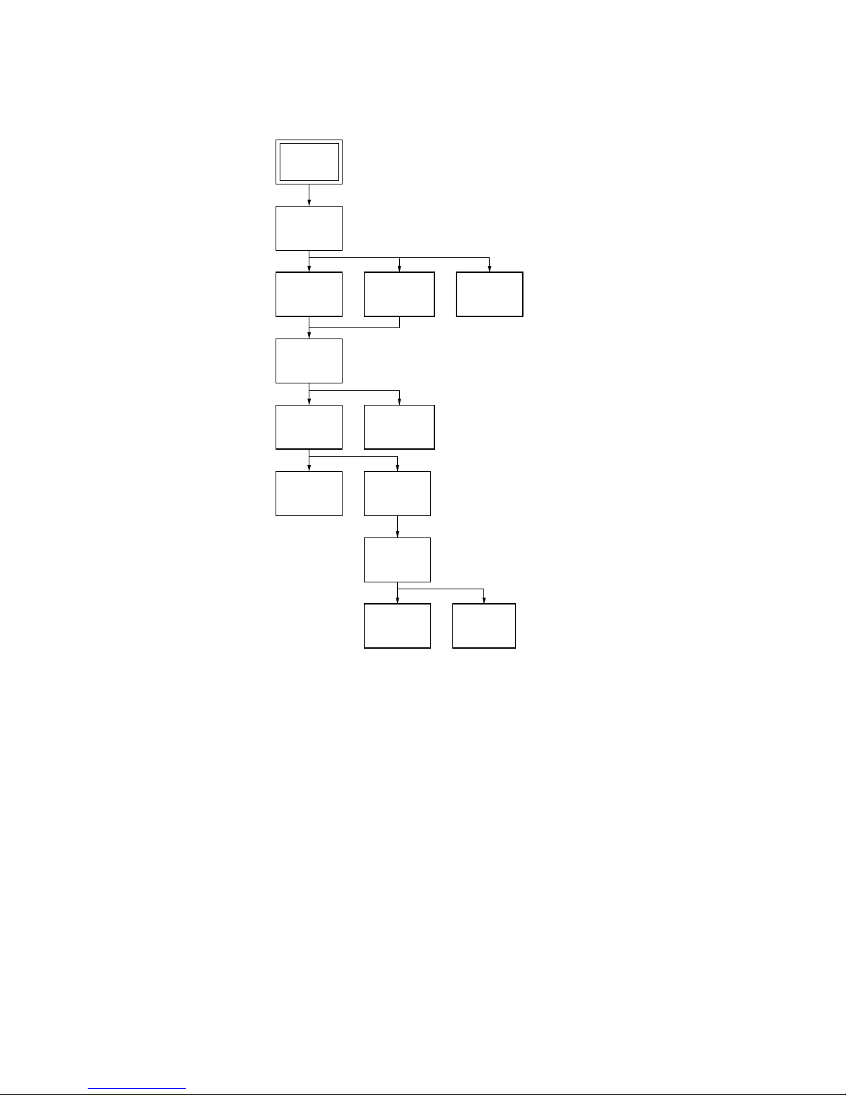
SERVICE NOTE
Tray
(Page 2-2)
TK-47
Board
(Page 2-2)
Case
(Page 2-1)
MB-78
Board
(Page 2-1)
Front Panel
Section
(Page 2-1)
AU-197
Board
(Page 2-1)
MD Block
Ass’y
(Page 2-2)
Optical
Pick-up
(Page 2-3)
Skew
Motor
(Page 2-2)
Spindle
Base
(Page 2-3)
Sled
Motor
(Page 2-3)
Spindle
Motor
(Page 2-3)
Set
1. DISASSEMBLY
• This set can be disassembled in the order shown below.
– 5 –
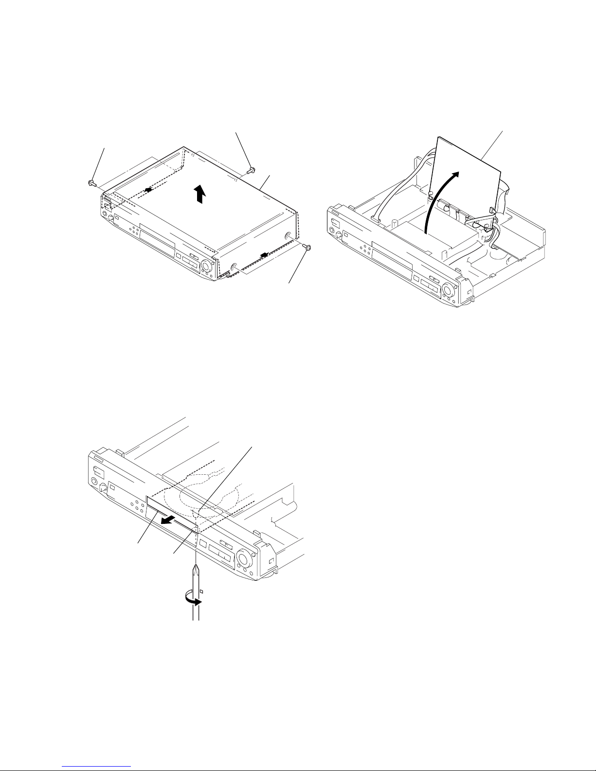
2. NOTE ON REMOVE THE CASE
1) Remove six tapping screws. (See Fig. 1)
2) Open the side of case. (See Fig. 1)
3) Remove the case as lift straight. (See Fig. 1)
Fig. 1
3. DISK REMOVAL PROCEDURE
(at POWER OFF)
1) Insert a cross-tip screwdriver into a hole at the bottom, and
rotate the cam gear 1 in direction A. (See Fig. 2)
Note: To prevent a damege of cam gear, rotate it in direction
A by 1/4 turn.
2) Draw out the tray 2 in direction B by hand, and remove a
disk. (See Fig. 2)
Fig. 2
4. HOW TO SERVICE MB-78 BOARD
1) Remove the case from the set. (Refer to 2-1)
2) Remove the cover (upper). (Refer to 2-3)
3) Set the MB-78 board as shown in Fig. 3.
Note: Do not disconnect wiring.
Fig. 3
Two tapping screws
Two tapping screws
Case
Two tapping screws
1 Cam gear
2 Tray
B
A
Hole
MB-78 board

– 6 –
5. NOTE ON MOUNTEING SLED MOTOR
1) Push the sled motor ass’y 1 toward direction A. (See Fig. 4)
2) Tighten two screws 2 (M1.7 × 2.5).
Fig. 4
3) Raising the MD block ass’y 3 90 º with the side down.
confirm that the optical pick-up 4 falls by self weight.
(See Fig. 5)
4) Further, with the front side of MD block ass’y 3 up, confirm
that the optical pick-up falls by self weight.
Fig. 5
1 Sled motor ass’y
2 Two screws (M1.7 × 2.5)
A
3 MD block ass’y
4 Optical pick-up
Upper
Lower Front side
Upper
Lower
Front side
– 7 –
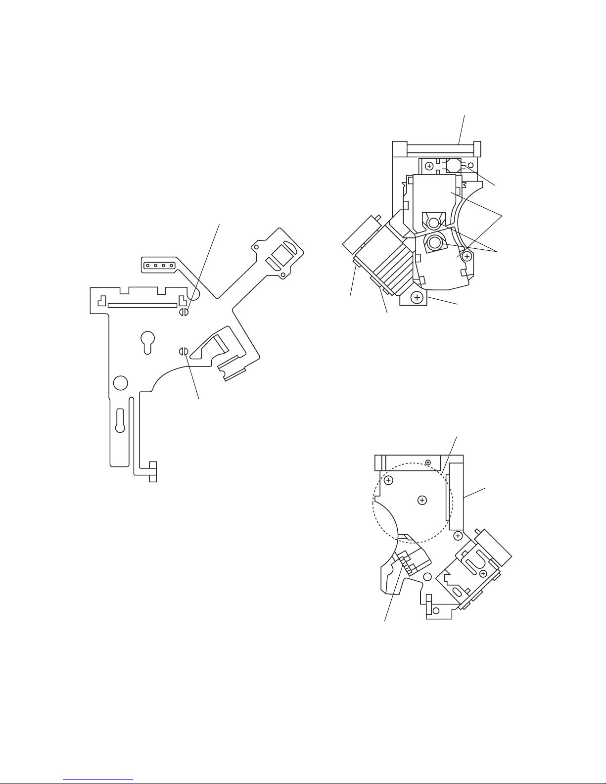
6. REPLACING OPTICAL PICK-UP
6-1. Handling
1) A red laser diode for DVD requires more attention to static
electricity than general infrared laser diodes for CD.
Because its durability to static electricity is far weaker than
that of infrared laser diodes, always use an earth band when
handling the optical pick-up block as service parts.
2) As for the flexible board KHS-180A (RP) packed as service
parts, the short lands have been soldered to protect from static
electricity. Accordingly, remove solders when replacing optical pick-up. (See Fig. 6)
Fig. 6 Flexible board
3) In handling the KHS-180A (RP), do not touch inhibited parts
shown in Fig. 7, but grip the slide base bearing and U-shaped
guide.
Fig. 7 KHS-180A (RP)
Touch inhibited par ts
• Objective lens
• Skew sensor
• Laser holder
• Laser coupler
• Flexible board
• OEIC
• Lens actuator covers
DVD short land
CD short land
Slide base bearing
Skew sensor
Lens actuator
covers
Objective lenses
U-shaped guide
OEIC
Laser holder
Flexible board
Connector
Laser coupler
– 8 –
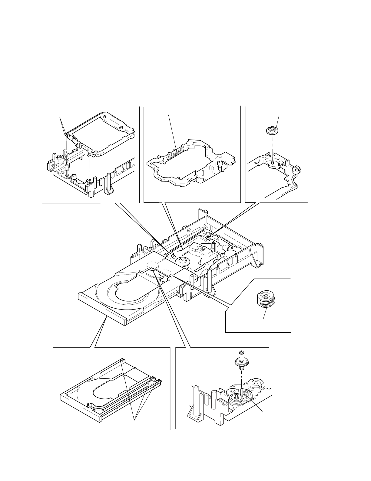
7. NOTE ON ASSEMBLING MECHANICAL DECK
7-1. Application of Grease
1) Gr ease must be applied if the following parts were replaced.
(See Fig. 8)
Note 1: Recommended grease is Foil KG-70MP.
Note 2: In applying grease, take care not to allow grease to
stick to other parts (particularly, rubber belt, spindle
motor, and optical pick-up)
Fig. 8
Base unit holder
2 bosses
Slide base Skew cam
Cam gear
Tray 3 grooves
Note:Add grease if tray
moves slowly.
Loading pulley shaft
Note:Add grease if tray
generates noise
periodically.

– 9 –
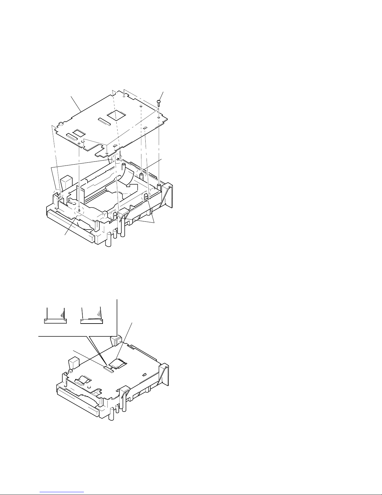
7-4. Deformation of Insulator
1) Assemble the spindle base into the base unit.
2) Lock with 4 shoulder screws. (See Fig. 11)
3) Check if 4 insulators deformed. (See Fig. 11)
Fig. 11
7-5. Note on Mounting FG-43 Board
1) Align two bosses. (See Fig. 12)
2) Fix the board securely with screws (PTPWH2 × 5). (The sen-
sor will not function normally if the board floats up.)
Fig. 12
7-2. Cleaning Spindle Motor Turntable
1) Remove the tray. (Refer to 2-7)
2) Clean the spindle motor turntable if disc antiskid rubber (black)
is dirty. (See Fig. 9)
Fig. 9
7-3. Aligning Phase of Cam Gear and
Drive Gear
1) Align triangle marks when assembling the cam gear and drive
gear. (See Fig. 10)
Fig. 10
Spindle motor
Turntable
Drive gear Cam gear
Align triangle marks.
Four step screws
Two insulators
Two insulators
Insulator
Good NG
Screw
(PTPWH2 × 5)
FG-43 board
Two bosses
– 10 –
7-6. Note on Mounting TK-47 Board
1) Align two bosses. (See Fig. 13)
2) Align four tabs. (See Fig. 13)
3) Fix the board securely with 3 screws (BV3 × 10). (The sensor
will not function normally if the board floats up.)
Fig. 13
7-7. Note on connecting OPT Harness
1) T he optical pick-up could be destroyed unless the OPT harness is connected normally to the connector. (See Fig. 14)
Fig. 14
TK-47 board
Three screws
(BV3 × 10)
Two claws
Boss
Two claws
Boss
OPT harness
Connector
Good NG
1-1
SECTION 1
GENERAL
DVP-S500D/S505D
This section is extracted from
DVP-S500D instruction manual.

1-2
1-3
1-4

1-5
1-6
1-7
1-8

1-9
1-10
1-11
1-12
1-12 E
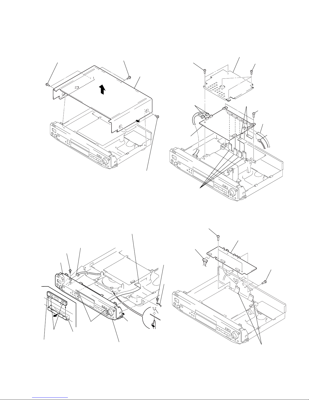
2-1
2-1. CASE REMOVAL 2-3. MB-78 BOARD REMOVAL
2-2. FRONT PANEL SECTION REMOVAL
DVP-S500D/S505D
SECTION 2
DISASSEMBLY
2-4. AU-197 BOARD REMOVAL
Note: Follow the disassembly procedure in the numerical order given.
1 Two tapping screws
2 Two tapping screws
3 Two tapping screws
4 Case
1 Connector
(CN001)
A
!£ Front panel section
3 Rotate the cam gear
in direction A.
!™ Claw
9 Lug
8 Screw
(B3)
2 Flat cable
4 Draw out the
tray by hand.
!¡ Two claws
6 Tray ornamental
panel ass’y
5 Two claws
0 Claw
7 Screw
(B3)
Cam gear
0 Four flat cables
(CN101, 252, 301, 452)
1 Two connectors
(CN001, 002)
4 Connector
(CN361)
5 Two screws
(B3)
3 Flat cable
(CN251)
8 Two screws
(B3)
2 Two flat cables
(CN301, 601)
6 Three screws
(B3)
7 Cover (upper)
9 MB-78
board
5 Two flat cables
(CN201, 203)
2 Four screws
(BVTP3 × 12)
4 AU-197 board
1 Connector
(CN205)
3 Two screws
(B3)
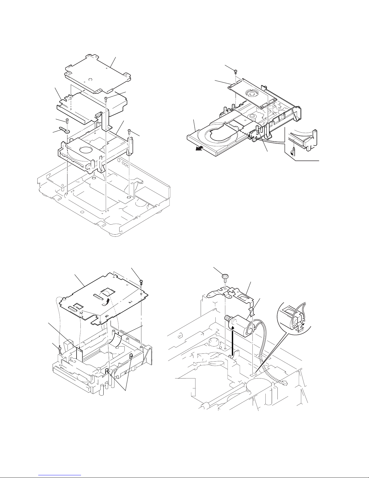
2-2
2-5. MD BLOCK ASS’Y REMOVAL 2-7. TRAY REMOVAL
2-6. TK-47 BOARD REMOVAL 2-8. SKEW MOTOR (M902) REMOVAL
5 Two screws
(B3)
4 Two screws
(B3)
7 MD block ass’y
2 Two screws
(B3)
3 Chassis
bracket (B)
1 Cover (lower)
6 Clamp
2 Flat cable
(spindle
motor)
(CN002)
1 Connector
(CN004)
5 Two claws
3 OP-15
flexible
board
(CN001)
4 Four screws
(BVTP3 × 10)
6 TK-47 board
A
3 Rotate the cam gear
in direction A.
5 Claw
6 Remove the
tray.
4 Pull the tray.
2 Press pully bracket
1 Two screws
(BVTP3 × 10)
2 Claw
4 Skew motor
(M902)
3 Skew gear retainer
1 Screw
(PTTWH2 × 5)
 Loading...