

Sony PVM-20M2MDJ, PVM-14M2MDE, PVM-20M2MDU, PVM-20M2MDE, PVM-20M2MDA Instructions For Use Manual
...
3-861-644-05 (1)
Trinitr on
®
Color Video Monitor
取扱説明書
Instructions for Use Page 21
Mode d’emploi Page 39
Gebrauchsanweisung Seite 57
Instrucciones de uso Página 75
Istruzioni per l’uso Pagina 93
ページ
2
J
EN
F
D
ES
I
安全のための注意事項を守らないと、
警告
この取扱説明書には、事故を防ぐための重要な注意事項と製品の取り扱
いかたを示しています。この取扱説明書をよくお読みのうえ、製品を安
全にお使いください。お読みになったあとは、いつでも見られるところ
に必ず保管してください。
火災や人身事故になることがあります。
PVM-14M2MDJ/14M2MDU/14M2MDE/14M2MDA
PVM-20M2MDJ/20M2MDU/20M2MDE/20M2MDA
1997 by Sony Corporation
日本語
安全のために
ソニーのモニターは正しく使用すれば事故が起きないように、安全には十
分配慮して設計されています。しかし、内部に非常に高い電圧を使用して
いるので、まちがった使いかたをすると、火災や感電などにより死亡や大
けがなど人身事故につながることがあり、危険です。
事故を防ぐために次のことを必ずお守りください。
安全のための注意事項を守る
警告表示の意味
この取扱説明書および製品で
は、次のような表示をしていま
す。表示の内容をよく理解して
から本文をお読みください。
4〜6ページの注意事項をよくお読みください。製品全般の安全上の注意事
項が記されています。
7ページの「使用上のご注意」もあわせてお読みください。
定期点検をする
5年に1度は、内部の点検を、お買い上げ店またはソニーのサービス窓口に
ご依頼ください(有料)。
故障したら使わない
すぐに、お買い上げ店またはソニーのサービス窓口にご連絡ください。
万一、異常が起きたら
煙が出たら
•
異常な音、においがし
•
たら
内部に水、異物が入っ
•
たら
モニターを落とした
•
り、キャビネットを破
損したときは
1 電源を切る。
/
2 電源コードや接続ケーブルを
抜く。
3 お買い上げ店またはソニーの
サービス窓口に連絡する。
警告
この表示の注意事項を守らない
と、火災や感電などにより死亡
や大けがなど人身事故につなが
ることがあります。
注意
この表示の注意事項を守らない
と、感電やその他の事故により
けがをしたり周辺の物品に損害
を与えたりすることがありま
す。
注意を促す記号
注意
行為を禁止する記号
禁止
行為を指示する記号
火災
分解禁止
感電
水場での
使用禁止
プラグをコン
強制
セントから抜く
2
目次
警告 ‥‥‥‥‥‥‥‥‥‥‥‥‥‥‥‥‥‥‥‥‥‥‥‥
注意 ‥‥‥‥‥‥‥‥‥‥‥‥‥‥‥‥‥‥‥‥‥‥‥‥
主な特長 ‥‥‥‥‥‥‥‥‥‥‥‥‥‥‥‥‥‥‥‥‥‥‥
各部の名称と働き ‥‥‥‥‥‥‥‥‥‥‥‥‥‥‥‥‥‥‥
前面 ‥‥‥‥‥‥‥‥‥‥‥‥‥‥‥‥‥‥‥‥‥‥‥‥‥ 8
後面パネル ‥‥‥‥‥‥‥‥‥‥‥‥‥‥‥‥‥‥‥‥‥‥ 10
スクリーンメニューについて ‥‥‥‥‥‥‥‥‥‥‥‥‥
電源について ‥‥‥‥‥‥‥‥‥‥‥‥‥‥‥‥‥‥‥‥
サイドカバーの取り付けかた ‥‥‥‥‥‥‥‥‥‥‥‥‥
コントロールパネルカバーの取り付けかた ‥‥‥‥‥‥‥
お手入れ ‥‥‥‥‥‥‥‥‥‥‥‥‥‥‥‥‥‥‥‥‥‥
保証書とアフターサ−ビス ‥‥‥‥‥‥‥‥‥‥‥‥‥‥
主な仕様 ‥‥‥‥‥‥‥‥‥‥‥‥‥‥‥‥‥‥‥‥‥‥
この取扱説明書では、PVM-20M2MDJとPVM-14M2MDJの2機種について説明
しています。細かい違いについては本文中に説明があります。
4
5
7
8
12
15
16
16
17
17
18
J
日
本
語
この装置は、情報処理装置等電波障害自主規制協議会(VCCI)の基準
に基づくクラスA情報技術装置です。この装置を家庭環境で使用する
と電波障害を引き起こすことがあります。この場合には使用者が適
切な対策を講ずるよう要求されることがあります。
3
警告
火災
火災 感電
分解禁止
禁止
下記の注意を守らないと、
火災や感電により死亡や大けがにつながることがあります。
感電
キャビネットをはずさない、改造しない
内部には電圧の高い部分があり、キャビネットや裏ぶたなどをはずした
り、改造したりすると、火災や感電の原因となります。内部の調整や設
定、点検、修理は、お買い上げ店またはソニーのサービス窓口にご依頼く
ださい。
内部に水や異物を入れない
水や異物が入ると火災や感電の原因となります。
万一、水や異物が入ったときは、すぐに電源を切り、電源コードや接続
ケーブルを抜いて、お買い上げ店またはソニーのサービス窓口にご相談く
ださい。
電源コードを傷つけない
禁止
強制
禁止
電源コードを傷つけると、火災や感電の原因となります。
• 設置時に、製品と壁やラック、棚などの間に、はさみ込まない。
• 電源コードを加工したり、傷つけたりしない。
• 重いものをのせたり、引っ張ったりしない。
• 熱器具に近づけたり、加熱したりしない。
• 電源コードを抜くときは、必ずプラグを持って抜く。
万一、電源コードが傷んだら、お買い上げ店またはソニーのサービス窓口
に交換をご依頼ください。
規定の電源電圧で使う
この取扱説明書に記されている電源電圧でお使いください(交流100V)。
規定外の電源電圧での使用は、火災や感電の原因となります。
油煙、湯気、湿気、ほこりの多い場所では設置・使用しない
上記のような場所に設置すると、火災や感電の原因となります。
この取扱説明書に記されている仕様条件以外の環境での使用は、火災や感
電の原因となります。
3P-2P変換アダプターは使用しない
3Pの電源プラグを2Pに変換するアダプターは確実な接地・接続ができない
ため、感電の原因となることがあります。
禁止
4
注意
下記の注意を守らないと、
けがをしたり周辺の物品に損害を与えることがあります。
ぬれた手で電源プラグをさわらない
ぬれた手で電源プラグを抜き差しすると、感電の原因となることがありま
禁止
注意
注意
す。
接続の際は電源を切る
電源コードや接続ケーブルを接続するときは、電源を切ってください。感
電や故障の原因となることがあります。
指定された電源コード、接続ケーブルを使う
付属の、あるいは取扱説明書に記されている電源コード、接続ケーブルを
使わないと、感電や故障の原因となることがあります。
他の電源コードや接続ケーブルを使用する場合は、お買い上げ店またはソ
ニーのサービス窓口にご相談ください。
禁止
水場での
使用禁止
禁止
通風孔をふさがない
通風孔をふさぐと内部に熱がこもり、火災や故障の原因となることがあり
ます。風通しをよくするために次の項目をお守りください。
• 壁から10cm以上離して設置する。
• 密閉された狭い場所に押し込めない。
• 毛足の長い敷物(じゅうたんや布団など)の上に設置しない。
• 布などで包まない。
• あお向けや横倒し、逆さまにしない。
水のある場所に設置しない
水が入ったり、ぬれたりすると、火災や感電の原因となることがありま
す。雨天や降雪中、海岸や水辺での使用は特にご注意ください。
不安定な場所に設置しない
ぐらついた台の上や傾いたところなどに設置すると、モニターが落ちた
り、倒れたりして、けがの原因となることがあります。
また、設置・取り付け場所の強度を充分にお確かめください。
禁止
直射日光の当たる場所や熱器具の近くに設置・保管しない
内部の温度が上がり、火災や故障の原因となることがあります。
真夏の、窓を閉め切った自動車内では50℃を越えることがありますので、
ご注意ください。
5
下記の注意を守らないと、
注意
けがをしたり周辺の物品に損害を与えることがあります。
モニターは、2人以上で開梱・運搬する
モニターは見た目より重量があります。開梱や運搬は、けがや事故を防ぐ
注意
注意
禁止
ため、必ず2人以上で行ってください。1人で行うと腰を痛めることがあり
ます。
転倒、移動防止の処置をする
モニターをラックに取り付け・取りはずしをするときは、転倒・移動防止
の処置をしないと、倒れたり、動いたりして、けがの原因となることがあ
ります。安定した姿勢で注意深く作業してください。
また、ラックの設置状況、強度を充分にお確かめください。
モニターの上に乗らない、重いものを載せない
倒れたり、落ちたり、壊れたりして、けがの原因となることがあります。
プラグをコン
セントから抜く
注意
注意
お手入れの際は、電源を切って電源プラグを抜く
電源を接続したままお手入れをすると、感電の原因となることがあります。
移動させるときは電源コード、接続ケーブルを抜く
接続したまま移動させると、電源コードや接続ケーブルが傷つき、火災や
感電の原因となることがあります。
定期的に内部の掃除を依頼する
長い間掃除をしないと内部にホコリがたまり、火災や感電の原因となるこ
とがあります。1年に1度は、内部の掃除をお買い上げ店またはソニーの
サービス窓口にご依頼ください(有料)。
特に、湿気の多くなる梅雨の前に掃除をすると、より効果的です。
6

主な特長
画像
解像度
トリニトロン1)管の採用により、中心部の解像度が600本以上の鮮
明な画像が得られます。
くし形フィルター
くし形フィルターの採用により、NTSC信号のクロスカラー妨害
(文字のまわりの虹)やカラーノイズ(色のにじみ)をなくし、
きめ細かで透明度の高い画像が得られます。
ビームカレントフィードバック回路
この回路の採用により、長期間安定したホワイトバランスが得ら
れます。
入力
2カラー方式
NTSC、PALの2つのカラー方式に対応でき、切り換えは自動で
す。入力信号に合った方式で画像を再現します。
アナログRGB/コンポーネント入力端子
ビデオ機器のアナログRGB、コンポーネント信号を入力できま
す。前面パネルのRGB/COMPONENT切り換えボタンでAまたは
Bを選び、スクリーンメニューでRGBまたはコンポーネントを選
びます。
Y/C入力端子(S入力端子)
ビデオ機器などの映像信号を、輝度信号(Y)と色信号(C)の2
つに分離したまま入力できます。これにより、従来のコンポジッ
ト信号にありがちだった信号間の干渉による色のにじみやちらつ
きの少ない、鮮明な画像が得られます。
外部同期信号(EXTSYNC)入力端子
外部同期信号発生器などからの同期信号を入力できます。RGBま
たはコンポーネント信号をモニターするとき、スクリーンメ
ニューで外部同期に設定します。
BNC型入力端子の自動終端開放
(
マークがついている端子のみ)
後面パネルのBNC型入力端子は、出力端子に何もつないでいない
ときは、内部で75Ωに終端されています。出力端子にケーブルを
つなぐと、内部の75Ωが自動的に開放され、入力端子に入った信
号がそのまま出力されます(ループスルー)。
機能
スクリーンメニュー機能
スクリーンメニューを画面に出して、接続するシステムに最適な
モニターの設定や調整をすることができます。
オーバースキャンモード
画面サイズが約20パーセント拡大され、中央部分が見やすくなり
ます。
アンダースキャンモード
通常、画面外に走査されている信号まで画面に表示し、画像全体
をモニターすることができます。
ご注意
アンダースキャン時に、画面上端に赤青緑の走査線が見えること
がありますが、これは本体内部の動作によるもので、入力信号と
は関係ありません。ご了承ください。
スプリット機能
画面を上下二つに分けることができます。上の画面にはRGB/
COMPONENTA入力端子からの信号をモニターし、下の画面に
はRGB/COMPONENTB入力端子からの信号をモニターします。
上下の画面を比較して見ることができます。
自動/手動消磁機能
ブラウン管は、電源を入れたときに自動的に消磁されます。
また、電源を入れたまま消磁するときは、DEGAUSSボタンを押
すと消磁できます。
サイドカバーとフロントパネルカバー
医薬品などの飛沫がモニター内に入るのを防ぐためのサイドカ
バーと、誤って前面パネルのボタンやつまみに触れるのを防ぐた
めのフロントパネルカバーが付属しています。
EIA規格の19インチラックに収納可能
別売りのマウンティングブラケットMB-502B(PVM-14M2MDJ
用)またはSLR-103A(PVM-20M2MDJ用)を使うと、EIA19イン
チラックにマウントすることができます。マウント方法について
はマウンティングブラケットの取扱説明書をご覧ください。
..............................................................................................................................................................................................................................................................
1) トリニトロンはソニー株式会社の登録商標です。
7
各部の名称と働き
前面
RESET
RGB/COMPONENT
A
B
OVER
UNDER
SCAN
SCAN
SPLIT
MENU
EXIT
SELECT
ENTER
LINE
AB
DEGAUSS
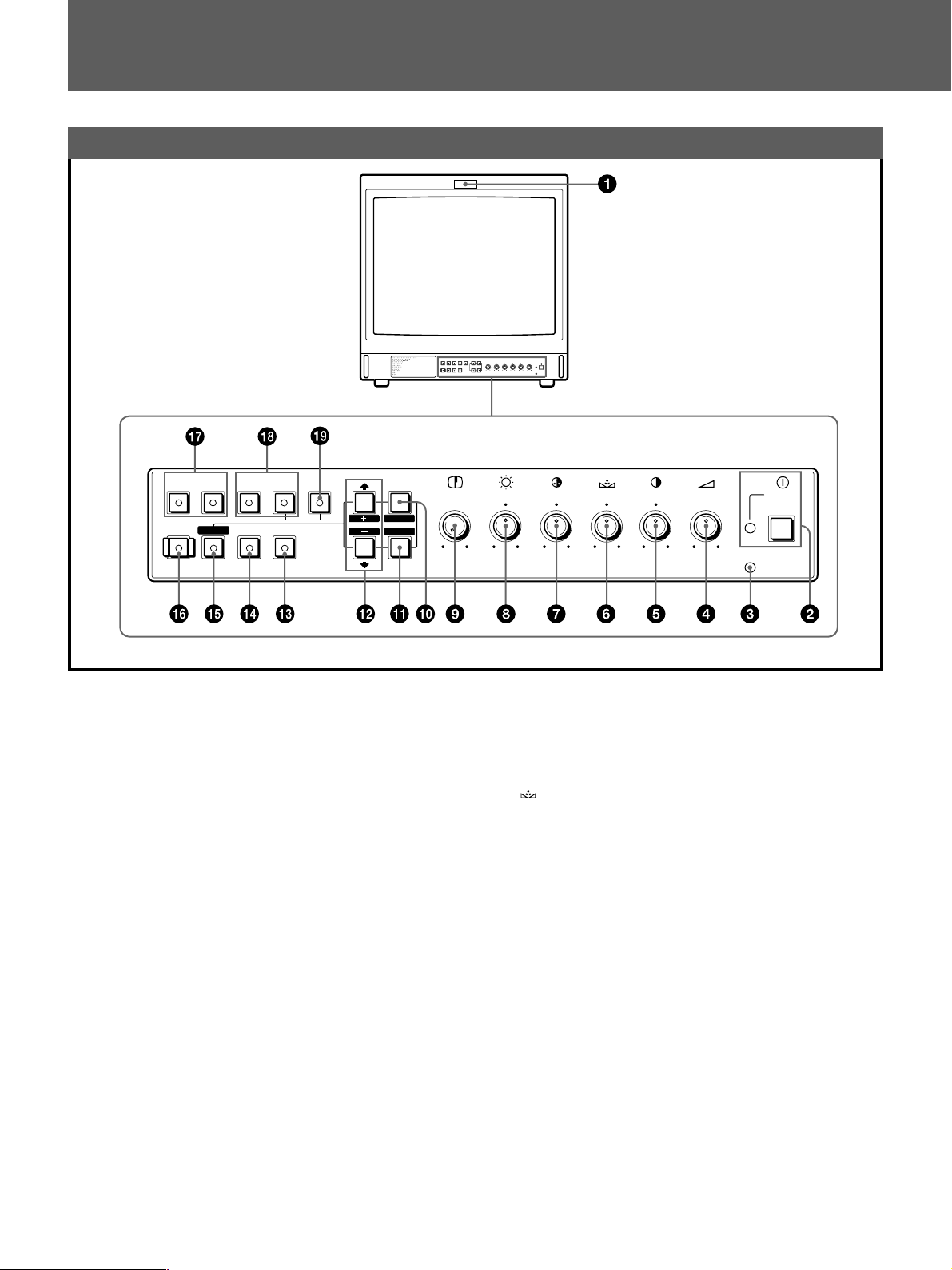
1 タリーランプ
ランプが点灯します。(タリー制御の配線が必要です。)
◆ピン配列については20ページをご覧ください。
2 UPOWER(電源)スイッチとインジケーター
スイッチを押し込むと電源が入り、インジケーター(緑)が
点灯します。もう一度押すと、電源が切れます。
3 REMOTEインジケーター
このインジケーターは、以下の場合に点灯します。
• スクリーンメニューのPRESETメニューで、ONを選択した
とき。
• スクリーンメニューのREMOTE(RS-232C)メニューで、
REMOTEONLYまたはREMOTE&LOCALを選択したと
き。
• REMOTE1端子(8ピンミニDIN)で、リモートONを選択
したとき。
APERTURE
MIN
MAX
POWER
REMOTE
– +
MIN
CONTRAST
PHASECHROMABRIGHT
MAX
PUR GRN MIN MAX MIN MAX
VOLUME
5 >CONTRAST調整つまみ
右へ回すと、コントラストが強くなります。
左へ回すと、コントラストが弱くなります。
PHASE(色相)調整つまみ
6
この調整つまみは、NTSCのカラー方式の信号にだけ働きま
す。
右へ回すと、肌色が緑がかります。
左へ回すと、肌色が紫がかります。
7 ¯CHROMA(色の濃さ)調整つまみ
右へ回すと、色が濃くなります。
左へ回すと、色が薄くなります。
8 ¨BRIGHT(明るさ)調整つまみ
右へ回すと、画面が明るくなります。
左へ回すと、画面が暗くなります。
4 ÁVOLUME(音量)調整つまみ
右へ回すと、音量が大きくなります。
左へ回すと、音量が小さくなります。
8
つづく
9 ŒAPERTURE調整つまみ
右へ回すと、くっきりとした画像になります。
MINの位置で補正のかからないフラットの状態になります。
ご注意
PHASE、CHROMA、APERTUREの各調整つまみはRGB信号
の映像には働きません。
PHASE調整つまみはコンポーネント信号の映像には働きませ
ん。
0 MENU(EXIT)ボタン
メニューを画面に出すときに押します。
ボタンを押すごとに、ひとつ前のメニューに戻ります。
!¡ ENTER(SELECT)ボタン
メニューで内容を決定するときに使います。
!™ 選択>(+)/.(−)ボタン
メニューでカーソル(z)を動かしたり、数値を調整したりす
るときに使います。
!£ OVERSCANボタン
オーバースキャンモードにするときに押します(LED点灯)。
画面サイズが約20パーセント拡大され、中央部分が見やすく
なります。もとの画面サイズに戻すときも、このボタンを押
します。
!•RGB/COMPONENTA/B切り換えボタン
モニターしたい入力信号を選びます(LED点灯)。
A:RGB/COMPONENTA端子からの信号をモニターする
ときに押します。
B:RGB/COMPONENTB端子からの信号をモニターする
ときに押します。
!ª SPLITボタン
RGB/COMPONENTA入力端子とRGB/COMPONENTB入力
端子からのRGB信号を選んでいるときに、このボタンを押す
と画面が上下二つに分かれます。二つのRGB信号を同時にモ
ニターすることができます。
ご注意
RGB/COMPONENTA入力端子とRGB/COMPONENTB入力
端子に入力される信号は同期がとれていることを確認してく
ださい。
!¢ UNDERSCANボタン
アンダースキャンモードにするときに押します(LE D 点
灯)。画面サイズが約5%縮小され、ラスターの四隅まで画面
に表示されます。もとの画面サイズに戻すときも、このボタ
ンを押します。
!∞ RESETボタン
メニュー動作中に、調整中の項目の値を出荷時の値に戻すと
きに押します。
!§ DEGAUSS(消磁)ボタン
消磁したいとき、このボタンを1回押します。
再度使用するときは10分以上間隔をおいてください。
ご注意
消磁中は、画面が垂直方向に流れます。
!¶LINEA/B切り換えボタン
モニターしたい入力信号を選びます(LED点灯)。
A:LINEA端子からの信号をモニターするときに押します。
B:LINEB端子からの信号をモニターするときに押します。
9
各部の名称と働き
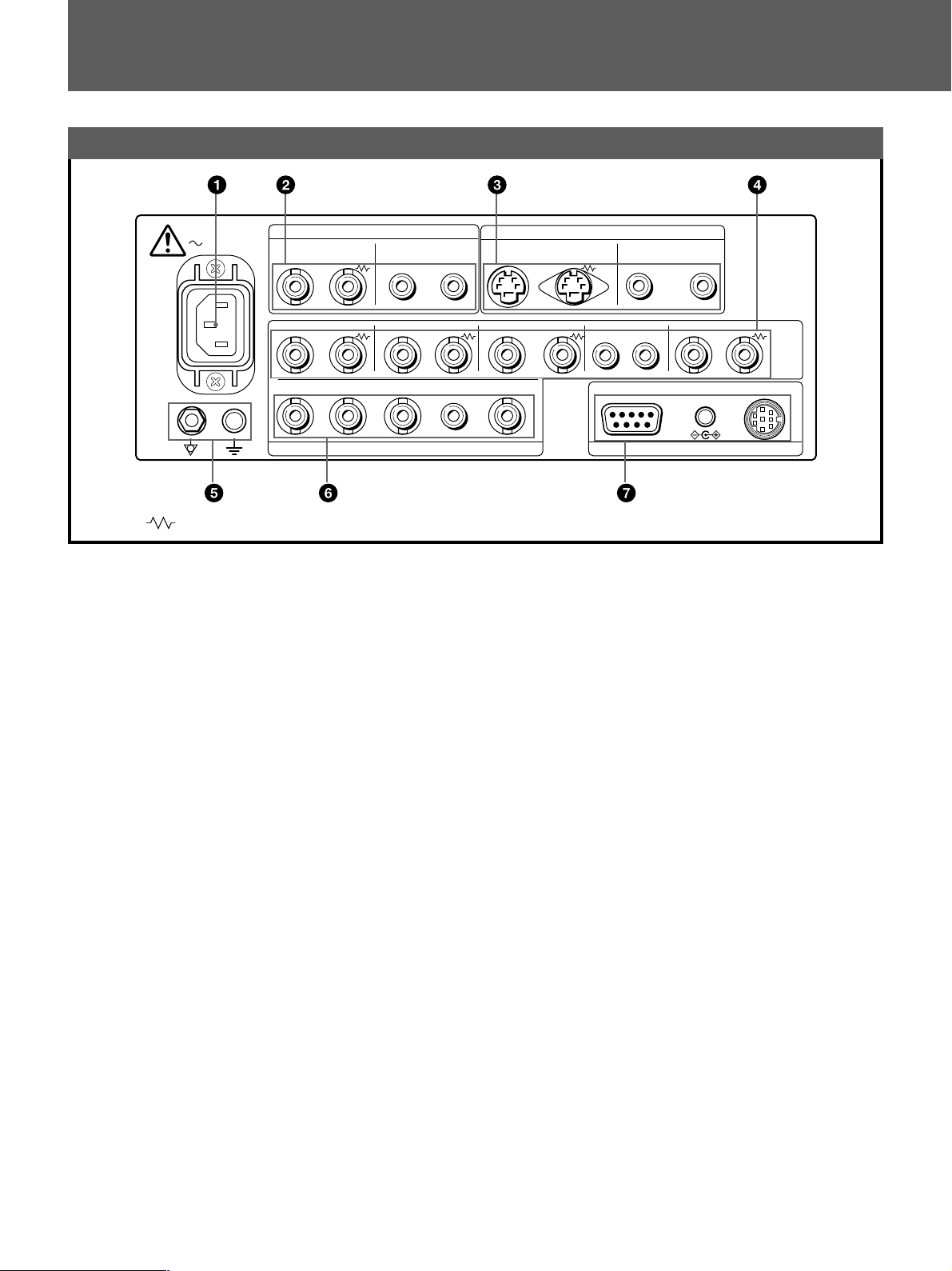
後面パネル
AC IN
( マークは75Ω自動終端を示します。)
VIDEO AUDIO
R/R–Y G/Y B/B–Y
A
IN
R/R–Y
B
IN
LINE A
IN OUTIN OUT
OUT IN OUT IN OUT IN OUT IN OUT
G/Y B/B–Y
IN IN
RGB/COMPONENT
1 ACINソケット
付属の電源コードを接続します。
2 LINEA入出力端子
コンポジットビデオ信号と音声信号のライン入力端子、およ
び、それぞれのループスルー出力端子があります。
この端子に入力した信号をモニターするには、前面パネルの
LINEA切り換えボタンを押します(LED点灯)。
VIDEOIN(映像入力)端子(BNC型)
VTRやカラービデオカメラの映像出力端子と接続します。
ブリッジ接続のときは、他のモニターの映像出力端子と接続
します。
VIDEOOUT(映像出力)端子(BNC型)
VIDEOIN端子に接続した映像信号を出力します(ループス
ルー)。VTRや他のモニターの映像入力端子と接続します。
この端子にケーブルをつなぐと、入力の75Ω終端が自動的に
開放され、VIDEO IN端子に入力された信号がこの端子から
出力されます。
AUDIOIN(音声入力)端子(ピンジャック)
VTRやマイクなどの音声出力端子と接続します。
ブリッジ接続のときは、他のモニターの音声出力端子と接続
します。
AUDIOOUT(音声出力)端子(ピンジャック)
AUDIOIN端子に接続した音声信号を出力します(ループス
ルー)。VTRや他のモニターの音声入力端子と接続します。
10
IN OUT
EXT SYNC
AUDIO
IN IN
3 LINEB入出力端子
4 RGB/COMPONENTA入出力端子
LINE B
Y/C
IN OUT
AUDIO
AUDIO
REMOTE
EXT SYNC
8V/0.8A
REMOTE 1DC OUTRS-232C
Y/C分離入出力端子と音声信号のライン入力端子、および、
それぞれのループスルー出力端子があります。
この端子に入力した信号をモニターにするには、前面パネル
のLINEB切り換えボタンを押します(LED点灯)。
Y/CIN端子(4ピンミニDIN)
VTRやビデオカメラなど、外部の機器のY/C分離出力端子と
接続します。
Y/COUT端子(4ピンミニDIN)
Y/C IN端子に接続したY /C 信号を出力します(ループス
ルー)。VTRや他のモニターなど外部の機器のY/C分離入力
端子と接続します。
この端子にケーブルをつなぐと、入力の75Ω終端が自動的に
開放され、Y/CIN端子に入力された信号がこの端子から出力
されます。
AUDIOIN(音声入力)端子(ピンジャック)
VTRやマイクなどの音声出力端子と接続します。
ブリッジ接続のときは、他のモニターの音声出力端子と接続
します。
AUDIOOUT(音声出力)端子(ピンジャック)
AUDIOIN端子に接続した音声信号を出力します(ループス
ルー)。VTRや他のモニターの音声入力端子と接続します。
RGB信号、またはコンポーネント信号の入力、および、それ
ぞれのループスルー出力端子があります。この端子に入力し
た信号をモニターするには、まず前面パネルのRGB/
COMPONENTA切り換えボタンを押します(LED点灯)。

つづく
次に、RGBA SYSTEMメニューの4項目の中から一つを選
び、RGBまたはCOMPONENT、内部同期または外部同期を
設定します。
◆
メニューの操作については、12〜14ページをご覧ください。
R/R-YIN、G/YIN、B/B-YIN端子(BNC型)
RGB ASYSTEMメニューでRGB-INT SYNCまたは
COMP-INTSYNCを選択したときは、G/Yチャンネルに
含まれている同期信号で動作します。
アナログRGB信号をモニターするとき:
ビデオカメラのアナログRGB出力端子と接続します。
コンポーネント信号をモニターするとき:
ソニーのベータカムビデオカメラなどのR-Y/Y/B-Yコンポー
ネント出力端子と接続します。
R/R-YOUT、G/YOUT、B/B-YOUT端子(BNC型)
それぞれ、R/R-YIN、G/YIN、B/B-YIN端子に接続した映像
信号を出力します(ループスルー)。
これらの端子にケーブルをつなぐと、入力の75Ω終端が自動
的に開放され、R/R-YIN、G/YIN、B/B-YIN端子に入力され
た信号が、これらの端子から出力されます。
アナログRGB信号を出力するとき:
ビデオプリンターや他のモニターのアナログRGB入力端子
と接続します。
コンポーネント信号を出力するとき:
ソニーのベータカムビデオレコーダーなどのR-Y/Y/B-Yコン
ポーネント入力端子と接続します。
AUDIOIN(音声入力)端子(ピンジャック)
アナログRGBまたはコンポーネント信号を入力するとき、こ
の端子に音声信号を入力します。
AUDIOOUT(音声出力)端子(ピンジャック)
AUDIOIN端子に接続した音声信号を出力します。(ループス
ルー)。
EXTSYNCIN(外部同期入力)端子(BNC型)
本機を外部同期で動作させるとき、同期信号発生器などから
の信号を入力します。
この端子に入力した同期信号を使う場合はRGBASYSTEMメ
ニューでRGB-EXTSYNCまたはCOMP-EXTSYNCを
選びます。
EXTSYNCOUT(外部同期出力)端子(BNC型)
IN端子に接続した同期信号を出力します(ループスルー)。
本機と同期して動作させる他のビデオ機器の外部同期入力端
子と接続します。
この端子にケーブルをつなぐと、入力の75Ω終端は自動的に開放
され、IN端子に入力された信号が、この端子から出力されま
す。
5 アース(1/Y)端子
アース線をこの端子に接続します。
6 RGB/COMPONENTB入力端子
RGB信号、またはコンポーネント信号の入力端子。この端子
に入力した信号をモニターするには、まず前面パネルのRGB/
COMPONENTB切り換えボタンを押します(LED点灯)。
次に、RGBBSYSTEMメニューの4項目の中から一つを選
び、RGBまたはCOMPONENT、内部同期または外部同期を
設定します。
◆
メニューの操作については、12〜14ページをご覧ください。
R/R-YIN,G/YIN,B/B-YIN端子(BNC型)
RGBB SYSTEMメニューでRGB-INT SYNCまたは
COMP-INTSYNCを選択したときは、G/Yチャンネルに
含まれている同期信号で動作します。
アナログRGB信号をモニターするとき:
ビデオカメラのアナログRGB出力端子と接続します。
コンポーネント信号をモニターするとき:
ソニーのベータカムビデオカメラなどのR-Y/Y/B-Yコンポー
ネント出力端子と接続します。
AUDIOIN(音声入力)端子(ピンジャック)
アナログRGBまたはコンポーネント信号を入力するとき、こ
の端子に音声信号を入力します。
EXTSYNCIN(外部同期入力)端子(BNC型)
本機を外部同期で動作させるとき、同期信号発生器などから
の信号を入力します。
この端子に入力した同期信号を使う場合はRGBBSYSTEMメ
ニューでRGB-EXTSYNCまたはCOMP-EXTSYNCを
選びます。
7 REMOTE端子
RS-232C端子(DSUB9ピン)
外部機器のRS-232Cコントロール端子に接続します。接続され
た外部機器よりコントロールコマンドを送ることで、モニ
ターの操作を行うことができます。
◆詳しくはプログラマー用インターフェース解説書(別冊)
をご覧ください。
REMOTE1端子(8ピンミニDIN)
外部機器のタリー出力端子に接続します。接続された外部機
器によって本機前面のタリーランプが点灯したり、消えたり
します。この端子には接点出力のリモコンを接続することも
できます。
◆REMOTE端子のピン配列については20ページをご覧くださ
い。
DCOUT(直流電源出力)8V/0.8A端子(極性統一型プラグ)
他の機器に8V/0.8Aの電源を出力します。
11
スクリーンメニューについて
スクリーンメニューについて
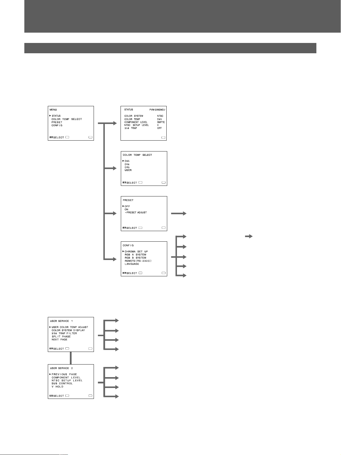
メニューの構成
モニター画面に表示されるスクリーンメニューの操作で、各種の
設定や調整をすることができます。下図は本機のメニューの構成
を示しています。
◆各メニューについて、詳しくは13ページ以降をご覧ください。
1メインメニュー
ENTER
2STATUSメニュー
MENU
3COLORTEMPSELECTメニュー
ENTER
4PRESETメニュー
ENTER
5CONFIGメニュー
ENTER
MENU
MENU
6PRESETADJUST画面
MENU
7CHROMASETUPメニュー
8RGBASYSTEMメニュー
9RGBBSYSTEMメニュー
!ºREMOTE(RS-232C)メニュー
MENU
!¡LANGUAGEメニュー
!™AUTOADJUST画面
12
ユーザーサービスモード
ENTER
ENTER
!£USERCOLORTEMPADJUSTメニュー
!¢COLORSYSTEMDISPLAYメニュー
!∞358TRAPFILTERメニュー
MENU
MENU
!§SPLITPHASEメニュー
!¶COMPONENTLEVELメニュー
!•NTSCSETUPLEVELメニュー
!ªSUBCONTROL画面
@ºVHOLD画面
つづく
A
M
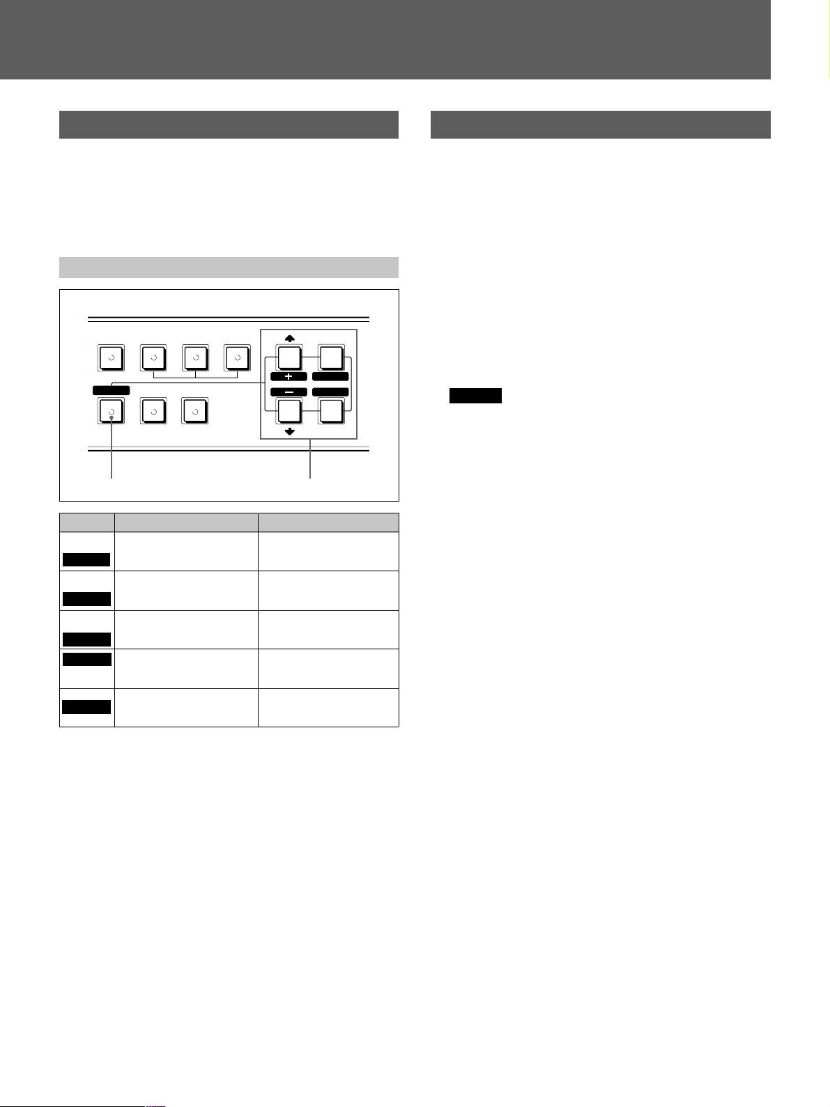
メニューの操作方法
メニュー操作は、前面パネルの5つのボタンを使って行います。メ
インメニューを表示させるには、MENU(EXIT)ボタンを押しま
す。メニューの各画面で操作できるボタンは画面のいちばん下の
行に常に表示されます。
各ボタンの働き
RGB/COMPONENT
ABB SPLIT
RESET
BLUE
UNDER
ONLY
リセットボタン メニュー操作ボタン
ボタン
MENU
EXIT
ENTER
SELECT
RESET
選択メニューのとき
前画面のメニューに戻り
ます。
選択項目を決定します。
>
カーソル(z )を上に動 か
+
します。
–
カーソル(z )を下に動 か
.
します。
SCAN
OVER
SCAN
調整画面のとき
前画面のメニューに戻り
ます。
調整項目を選択します。
調整値を上げます。
調整値を下げます。
現在調整中の項目の値を
出荷時の値に戻します。
MENU
EXIT
SELECT
ENTER
メニュー内容の説明
各メニューの内容を説明します。
各項目の[]の表記は出荷時の設定です。
1 メインメニュー
設定/調整項目を選択します。ENTER(SELECT)ボタンで次の
メニューに進みます。
2 STATUSメニュー
現在の設定を表示します。
3 COLORTEMPSELECTメニュー
色温度をD65、D56、D93、USERから設定します。USERモー
ドは異なる色温度に調整する こと がで きます(色温度の調整に
は測定器が必要です)。 [D65]
ご注意
• USERモードの色温度は、3200K〜10000Kの範囲で調整でき
ます。
• D93は、内視鏡等の用途に適しています。
• D56は、生物顕微鏡等の用途に適しています。
• USERモードの調整は、ユーザーサービスモードのUSER
COLORTEMPADJUSTメニュー(!£)で行います。
◆詳しくは、14ページのUSERCOLORTEMP ADJUSTメ
ニュー(!£)をご覽ください。
4 PRESETメニュー
ONを選択すると、前面パネルのすべてのつまみが働かなくな
り(REMOTEインジケーター点灯)、モニターは内部に記憶さ
れたプリセット(初期設定)値で働きます。プリセット値を調
整するときはPRESETADJUSTを選択します。 [OFF]
5 CONFIGメニュー
本機の設定や調整を行うときに選択します。
6 PRESETADJUST画面
CONTRAST、BRIGHT、CHROMA、PHASE、VOLUME、
APERTUREそれぞれのプリセット(初期設定)値を調整 しま
す。
7 CHROMASETUPメニュー
AUTOADJUST画面(!™)で、CHROMAとPHASE(NTSC信号
のみ)調整を行ったとき、ONにします。 [OFF]
8 RGBASYSTEMメニュー
RGB/COMPONENTA入力端子からの信号をモニターするとき
は、このメニューでRGBまたはCOMPONENTの設定および、
外部同期または内部同期の設定を行ってください。
[RGB-EXTSYNC]
13
スクリーンメニューについて
9 RGBBSYSTEMメニュー
RGB/COMPONENTB入力端子からの信号をモニターするとき
は、このメニューでRGBまたはCOMPONENTの設定、およ
び、外部同期または内部同期の設定を行ってください。
[RGB-EXTSYNC]
!º REMOTE(RS-232C)メニュー
以下の3種類の中から、使用するモードを選択します。
REMOTEOFF:
各種の設定を、前面パネルのボタンと調整つまみで行うとき。
リモートコントローラーは使用できません。
REMOTEONLY:
各種の設定をRS-232Cでコントロールするとき。
メニュー操作ボタンを除いて、前面パネル上での操作はでき
ません。
REMOTE&LOCAL:
前面パネルのボタン、および、RS-232Cでコントロールする
とき。
前面パネルの調整つまみは使用できません。
[REMOTEOFF]
!¡ LANGUAGEメニュー
メニュー表示を英、独、仏、伊、西の各国語に切り換えるこ
とができます。 [ENGLISH]
!™ AUTOADJUST画面
カラーバー信号(フル/SMPTE/EIA)を画面に出してENTER
(SELECT)ボタンを押すと、自動的にCHROMA、PHASE調整
が行われます。この調整を有効にするには、CHROMASET
UPメニュー(7)でONを選択します。
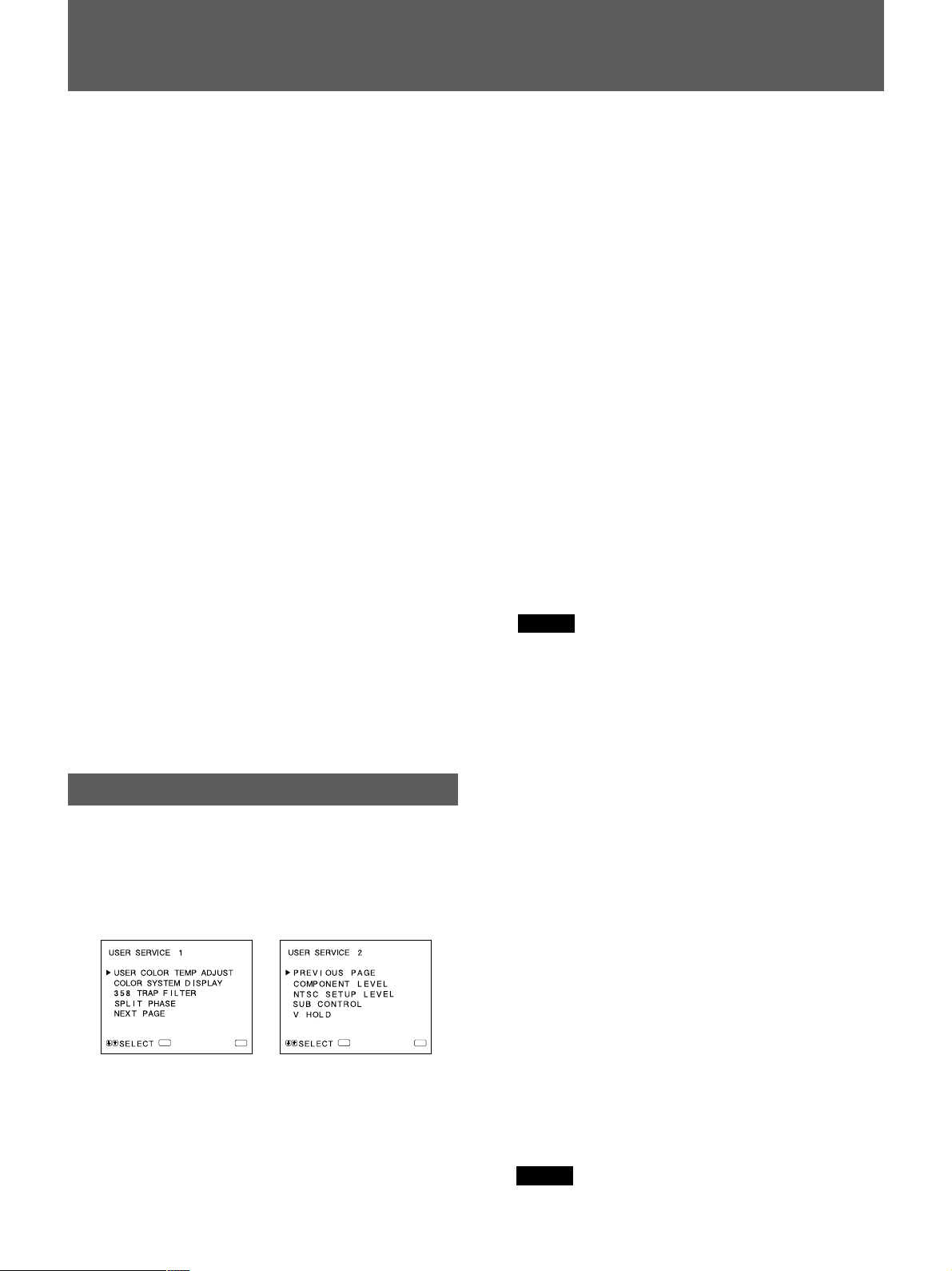
ユーザーサービスモードについて
上記以外の調整・設定を行うためのユーザーサービスモードがあ
ります。
ユーザーサービスモードへの入り方は、MENU(EXIT)ボタンを下
図のUSERSERVICE1が表示されるまで押し続けてください。
USERSERVICEモードの2ページ目に移るにはNEXTPAGEを、
1ページ目に戻るにはPREVIOUSPAGEを選びます。
COLORTEMPRANGE:
USERモードで色温度を調整する場合、調整しようとする色
温度が3200〜5000Kのときは、3200K-5000Kに、5000〜
10000Kのときは、5000K-10000KをADJUSTGAINとADJUST
BIASの調整前に選択します。
[5000K-10000K]
USERCOPY:
USERモードの色温度をD65、D56、D93に設定します。
!¢ COLORSYSTEMDISPLAYメニュー
AUTOを選択すると、入力を変更するたびに現在のカラーシス
テムが画面に数秒間だけ表示されます。 [AUTO]
!∞ 358TRAPFILTERメニュー
NTSC信号再生時にドット妨害が気になるとき、ONを選択す
ると低減します。通常はOFFにしておきます。 [OFF]
!§ SPLITPHASEメニュー
スプリット機能を使用しているとき、上下の画面の位置がず
れている場合に調整することができます。メニュー操作ボタ
ンの選択>(+)ボタンを押すたびに、下の画面(RGB/COMPONENTB入力端子からの信号をモニターしている)が左に移動
します。 [MIN]
ご注意
SPLITPHASEを調整する場合、下側の画面の上部にスキュー
エラーが起こることがあります。
!¶ COMPONENTLEVELメニュー
以下の3種類のなかから、入力されているコンポーネント信号
の種類を選択します。
N10/SMPTE: 100/0/100/0のコンポーネント信号のとき
BETA7.5:
100/7.5/75/7.5のコンポーネント信号のとき
BETA0: 100/0/75/0のコンポーネント信号のとき
[N10/SMPTE]
!• NTSCSETUPLEVELメニュー
NTSC 信号のセットアップのレベルを選択します。日本は0
で、アメリカでは7.5で運用されています。このため輸入ソフ
トには7.5のものがあります。 [0]
ENTER
MENU
ENTER
!£ USERCOLORTEMPADJUSTメニュー
このメニューで調整した値は、13ページのCOLORTEMPSELECTメニュー(3)でUSERを選択したときに働きます。
ADJUSTGAIN:
USERモードのカラーバランス(ゲイン)を調整します。
ADJUSTBIAS:
USERモードのカラーバランス(バイアス)を調整します。
14
!ª SUBCONTROL画面
前面パネルのCONTRAST、PHASE、CHROMA、BRIGHT調
MENU
整つまみの調整範囲を微調整します。これらのつまみは調整
範囲のまん中にクリックがありますので、クリック位置での
微調整に使用できます。
@º VHOLD画面
垂直同期の調整画面です。画面が流れてしまっているとき正
常に映るよう調整します。
ご注意
画面が流れてメニューの表示が読み取れないときは、なにも
接続されていない入力端子を選んでください。
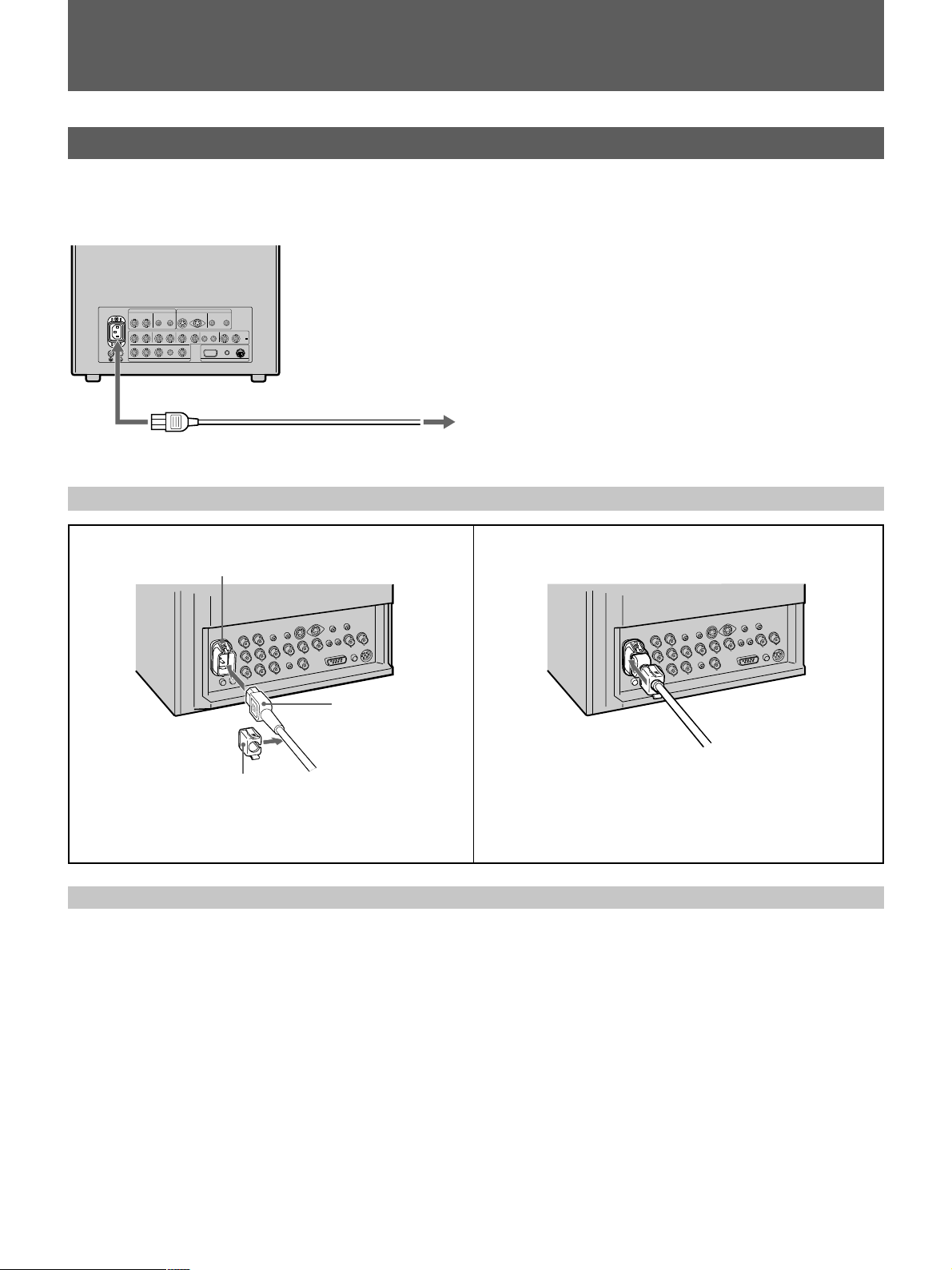
電源について
電源の使いかた
付属の電源コードを後面パネルのACINソケットに差し込み、壁
の電源に接続してお使いください。
ACINへ
電源コードを接続するには
1
電源コードを後面パネルのACINソケットに差し込み、付属の
ACプラグホルダーを電源コードに取り付けます。
ACINソケット
ACプラグホルダー
壁の電源へ
電源コード
2
ACプラグホルダーを本体側のホルダーにはめこみます。
電源コードをはずすには
ACプラグホルダーを上下からはさんで引きぬきます。
15
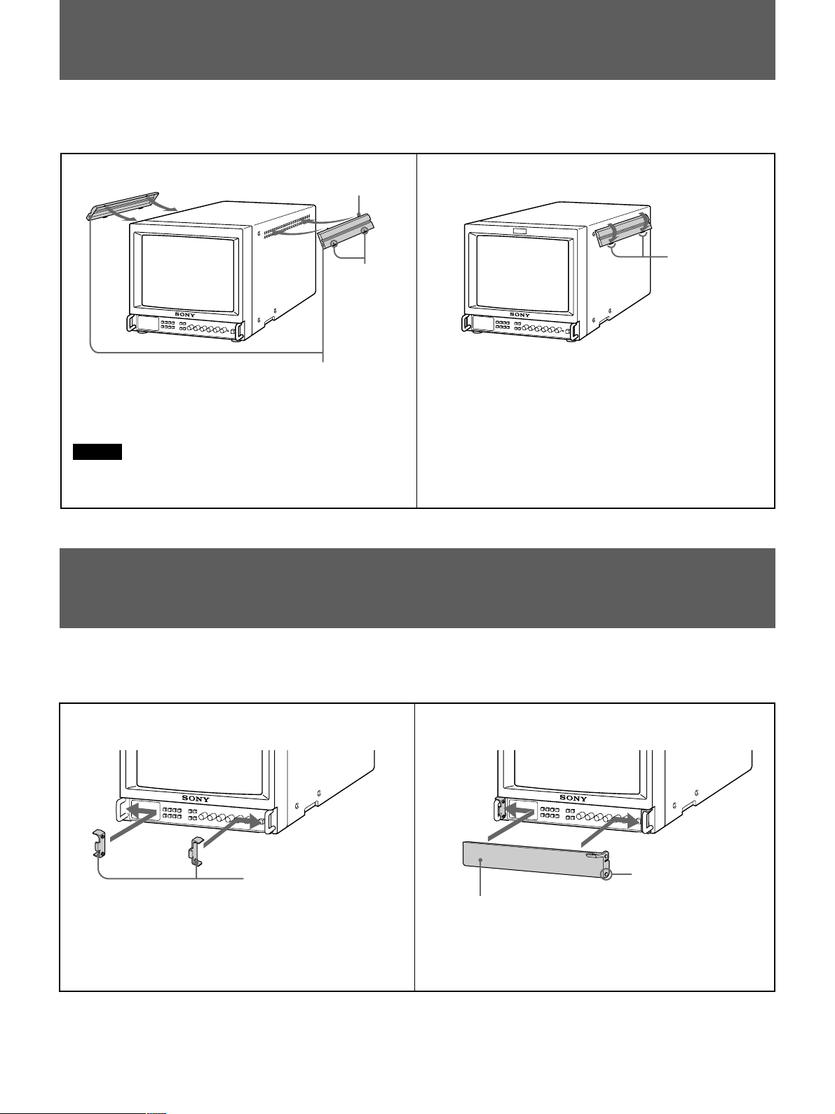
サイドカバーの取り付けかた
本体側面から医薬品などの飛沫が入り込むのを防ぐため、付属の
サイドカバーを取り付けてください。
1
サイドカバーの矢印を下にして、上部のつめを通風孔の最上段
にひっかけます。
ご注意
サイドカバーは通風孔がすべて隠れるように取り付けてくださ
い。
上部のつめ
矢印
サイドカバー
2
下部のつめ
下部のつめを指で押し上げ、通風孔の最下段にはめこみます。
左右両側とも取り付けてください。
コントロールパネルカバーの取り付けかた
誤ってボタンやつまみに触るのを防ぐため、付属のコントロール
パネルカバーを取り付けてください。
1
パネルヒンジ
パネルヒンジを左右の把手に内側から取り付けます。
2
コントロールパネルカバー
コントロールパネルカバーをたわませて、両側面の突起をパネル
ヒンジの下方の穴にはめこみます。
突起
16

お手入れ
保証書とアフターサービス
キャビネットや表面のガラスは柔らかい布でおふきください。
キャビネットの汚れがひどいときは、水で5〜6倍に薄めた中性洗
剤液に柔らかい布をひたし、かたくしぼってから汚れをふきとり
ます。このあと乾いた布でからぶきしてください。
シンナーやベンジンなどの薬品類は、表面の仕上げをいためた
り、表示が消えてしまうことがありますので、使用しないでくだ
さい。なお、お手入れのときは、必ず電源を切ってください。
ホコリは大敵
内部にホコリがたまると、故障や事故の原因になることがありま
す。いつも好調にお使いいただくため、年に一度は内部の掃除、
点検をお買い上げ店または担当セールスマンにご相談ください。
保証書
• この製品には保証書が添付されていますので、お買い上げの際
お受け取りください。
• 所定事項の記載内容をお確かめのうえ、大切に保存してくださ
い。
アフターサービス
調子が悪いときはまずチェックを
この説明書をもう一度ご覧になってお調べください。
それでも具合の悪いときはサービスへ
お買い上げ店、または添付の「サービス窓口・ご相談窓口のご案
内」にあるお近くのソニーサービス窓口にご相談ください。
保証期間中の修理は
保証書の記載内容に基づいて修理させていただきます。詳しくは
保証書をご覧ください。
保証期間経過後の修理は
修理によって機能が維持できる場合は、ご要望により有料修理を
させていただきます。
17

主な仕様
映像信号系
PVM-14M2MDJ/20M2MDJ
カラー方式 NTSC、PAL
解像度 600本
アパチャー補正度 0dB〜+6dB
周波数特性
LINE 10MHz±3dB(輝度信号)
RGB 10MHz±3dB
同期 AFC時定数1.0ms
画像系
PVM-14M2MDJ
ノーマルスキャン CRT有効画面の7%オーバースキャン
アンダースキャン CRT有効画面の5%アンダースキャン
オーバースキャン CRT有効画面の20%オーバースキャン
H直線性 4.0%以下(標準)
V直線性 4.0%以下(標準)
コンバージェンス
中心部: 0.4mm以下(標準)
周辺部: 0.5mm以下(標準)
ラスターサイズ安定度 H:1.0%V:1.5%
高電圧変動率 3.5%
色温度 D65/D56/D93/USER(調整可能温度
3,200K〜10,000K)
入力
LINEA入力端子
VIDEOIN BNC型1Vp-p±6dB、同期負
AUDIOIN ピンジャック(×1)−5dBu
LINEB入力端子
Y/CIN 4ピンミニDIN(×1)
◆ピン配列については20ページをご覧
ください。
AUDIOIN ピンジャック(×1)−5dBu
RGB/COMPONENTA/B入力端子
R/R-Y,G/Y,B/B-YIN:BNC型(×3)
R,G,B: 0.7Vp-p ±6dB(G チャンネルに負の同期
信号がある場合は、内部同期で使用可。
0.3Vp-p)
R-Y,B-Y: 0.7Vp-p±6dB
Y: 0.7Vp-p±6dB(75%クロミナンスの標準
カラーバー信号のとき)
AUDIOIN ピンジャック(×1)−5dBu
以上
EXTSYNCIN BNC型(×1)4Vp-p±6dB、同期負
REMOTE端子 DSUB9ピン(×1)、8ピンミニDIN(×1)
◆ピン配列については20ページをご覧
ください。
a)0dBu=0.775Vr.m.s
a)
、47kΩ以上
a)
、47kΩ以上
a)
、47kΩ
PVM-20M2MDJ
ノーマルスキャン CRT有効画面の7%オーバースキャン
アンダースキャン CRT有効画面の5%アンダースキャン
オーバースキャン CRT有効画面の20%オーバースキャン
H直線性 5.0%以下(標準)
V直線性 5.0%以下(標準)
コンバージェンス
中心部: 0.6mm以下(標準)
周辺部: 1.0mm以下(標準)
ラスターサイズ安定度 H:1.0%V:1.5%
高電圧変動率 4.0%
色温度 D65/D56/D93/USER(調整可能温度
3,200K〜10,000K)
出力
LINEA出力端子
VIDEOOUT BNC型(×1)ループスルー、
75Ω自動終端機能付き
AUDIOOUT ピンジャックループスルー
LINEB出力端子
Y/COUT 4ピンミニDIN(×1)ループスルー、
75Ω自動終端機能付き
AUDIOOUT ピンジャック(×1)ループスルー
RGB/COMPONENTA出力端子
R/R-Y,G/Y,B/B-YOUT:BNC型(×3)ループスルー
75Ω自動終端機能付き
AUDIOOUT ピンジャック(×1)ループスルー
EXTSYNCOUT BNC型(×1)
75Ω自動終端機能付き
DCOUT 8V/0.8A
内蔵スピーカー出力 0.8W
18

つづく
その他
PVM-14M2MDJ
CRT P22規格蛍光体
消費電流 1.2〜0.5A
電源 AC100〜240V、50/60Hz
動作条件
温度 0〜+40℃
湿度 30〜85%(結露のないこと)
気圧 700〜1,060hPa
保存・輸送条件
温度 −10〜+40℃
湿度 0〜90%(結露のないこと)
気圧 700〜1,060hPa
最大外形寸法(幅/高さ/奥行き)
約346×340×431mm(突起部含まず)
質量 約16.7kg
付属品 電源コード(1)
電源プラグホルダー(1)
サイドカバー(2)
コントロールパネルカバー(1)
パネルヒンジ(2)
リモートコントロールコネクター8ピン
ミニDIN(1)
プログラマー用インターフェース解説書
(1)
取扱説明書(1)
保証書(1)
セールス会社窓口のしおり(1)
質量 約30.0kg
付属品 電源コード(1)
電源プラグホルダー(1)
サイドカバー(2)
1)
コントロールパネルカバー(1)
パネルヒンジ(2)
リモートコントロールコネクター8ピン
ミニDIN(1)
プログラマー用インターフェース解説書
(1)
取扱説明書(1)
保証書(1)
セールス会社窓口のしおり(1)
本機の仕様および外観は、改良のため予告なく変更することがあ
りますが、ご了承ください。
本機は「高調波ガイドライン適合品」です。
PVM-20M2MDJ
CRT P22規格蛍光体
消費電流 1.5〜0.6A
電源 AC100〜240V、50/60Hz
1)
動作条件
温度 0〜+40℃
湿度 30〜85%(結露のないこと)
気圧 700〜1,060hPa
保存・輸送条件
温度 −10〜+40℃
湿度 0〜90%(結露のないこと)
気圧 700〜1,060hPa
最大外形寸法(幅/高さ/奥行き)
約450×458×503mm(突起部含まず)
..............................................................................................................................................................................................................................................................
1) AC100V以外で使用する場合は、必ず各電源電圧に対応する指定のACコードをご購入してからお使いください。(P.22参照)
19
主な仕様
12345
6789
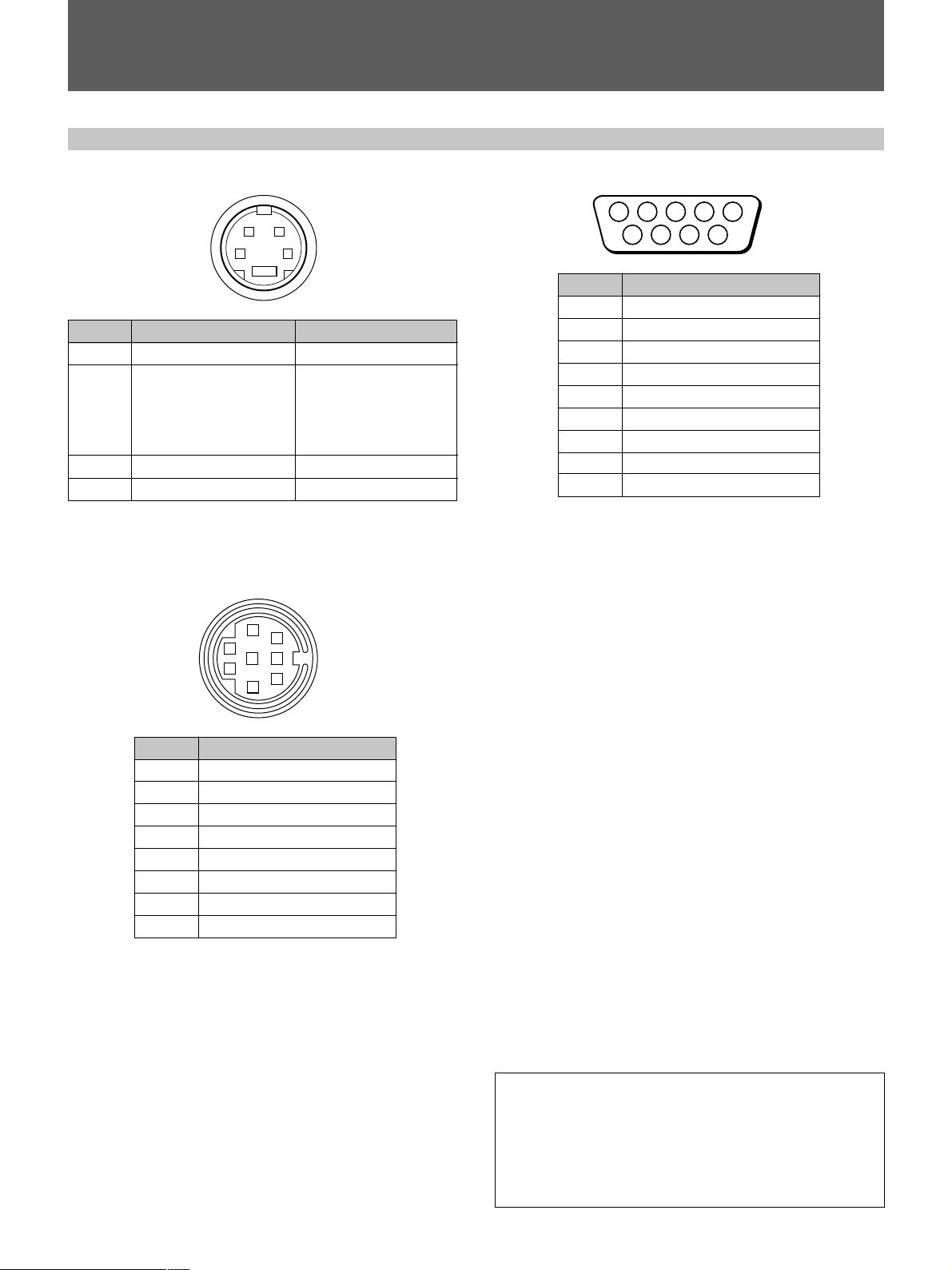
ピン配列
Y/CIN入力端子(4ピンミニDIN)
21
*
ピンNo.
Y入力
1
2
CHROMA
サブキャリア入力
GND(Y入力用)
3
GND(CHROMA入力用)
4
REMOTE1端子(8ピンミニDIN)
信号
5
2
4
1
3
34
信号レベル
1Vp-p、同期負、75Ω
300mVp-p(PAL)/286m
Vp-p(NTSC)、バースト
Y-C間遅延時間
0±100nsec、75Ω
アース
アース
8
7
6
RS-232C端子(DSUB9ピン)
ピンNo. 信号
―
1
2 受信データ
3 送信データ
―
4
5 アース
―
6
7 送信要求
8 送信可
9
―
ピンNo. 信号
1 リモートON/OFF
2ラインA
3アース
4 ラインB
5タリー
6 オーバースキャン
7 RGBA
8 RGBB
本機の仕様および外観は、改良のため予告なく変更することがあ
りますが、ご了承ください。
お問い合わせ
ソニーマーケティング株式会社
情報システム営業本部
メディカルマーケット営業部
東京都港区高輪4-10-18 〒108-0074
Tel.03-5792-2615 Fax.03-5792-2853
20

English
WARNING
c
Owner’s Record
The model and serial numbers are located at the rear.
Record these numbers in the spaces provided below.
Refer to these numbers whenever you call upon your
Sony dealer regarding this product.
Model No.
Serial No.
To prevent fire or shock hazard, do not expose the unit to
rain or moisture.
Dangerously high voltages are present inside the unit. Do
not open the cabinet. Refer servicing to qualified personnel
only.
In the event of a malfunction or when maintenance is
necessary, consult an authorized Sony dealer.
This unit contains substances which can pollute the
environment if disposed carelessly. Please contact our
nearest representative office or your local environmental
office in case of disposal of this unit.
Power Switch
The power switch is a functional switch only.
To isolate the set from the mains supply remove the mains
plug from the wall socket.
FOR CUSTOMERS IN THE UNITED KINGDOM
WARNING
THIS APPARATUS MUST BE EARTHED
IMPORTANT
The wires in this mains lead are coloured in accordance
with the following code:
GREEN-AND-YELLOW— EARTH
BLUE — NEUTRAL
BROWN — LIVE
As the colours of the wires in the mains lead of this
apparatus may not correspond with the coloured markings
identifying the terminals in your plug PROCEED AS
FOLLOWS:
The wire coloured GREEN AND YELLOW must be
connected to the terminal on the plug marked with the letter
E or by the safety earth symbol Y or coloured GREEN or
GREEN-AND-YELLOW.
The wire coloured BROWN must be connected to the
terminal marked with the letter L or coloured RED.
The wire coloured BLUE must be connected to the terminal
marked with the letter N or coloured BLACK.
FOR THE CUSTOMERS IN THE USA
This equipment has been tested and found to comply with
the limits for a Class A digital device, pursuant to Part 15 of
the FCC Rules. These limits are designed to provide
reasonable protection against harmful interference when the
equipment is operated in a commercial environment. This
equipment generates, uses, and can radiate radio frequency
energy and, if not installed and used in accordance with the
instruction manual, may cause harmful interference to radio
communications. Operation of this equipment in a residential area is likely to cause harmful interference in which case
the user will be required to correct the interference at his
own expense.
You are cautioned that any changes or modifications not
expressly approved in this manual could void your authority
to operate this equipment.
ATTENTION – When the product is installed in a
rack:
a) Elevated operating ambient temperature
If installed in a closed or multi-unit rack assembly, the
operating ambient temperature of the rack environment
may be greater than room ambient.
Therefore, consideration should be given to installing the
equipment in an environment compatible with the
manufacturer’s maximum rated ambient temperature of
0 to +40° (Tmra).
b) Reduced air flow
Installation of the equipment in a rack should be such
that the amount of air flow required for safe operation of
the equipment is not compromised.
c) Mechanical loading
Mounting of the equipment in the rack should be such
that a hazardous condition is not achieved due to
uneven mechanical loading.
d) Circuit overloading
Condideration should be given to the connection of the
equipment to the supply circuit and the effect that
overloading of circuits might have on overcurrent
protection and supply wiring.
Appropriate consideration of equipment nameplate
ratings should be used when addressing this concern.
e) Reliable earthing
Reliable earthing of rack-mounted equipment should be
maintained. Particular attention should be given to
supply connections other than direct connections to the
branch circuit (e.g., use of power strips).
EN
English
Ensure that your equipment is connected correctly — If you
are in any doubt consult a qualified electrician.
Be sure to connect the AC power cord to a grounded
outlet.
21
Warning
Important safeguards/notices for use in the
medical environments
1. All the equipments connected to this unit shall be
certified according to Standard IEC601-1, IEC950,
IEC65 or other IEC/ISO Standards applicable to the
equipments.
2. When this unit is used together with other equipment in
the patient area*, the equipment shall be either powered
by an isolation transformer or connected via an
additional protective earth terminal to system ground
unless it is certified according to Standard IEC601-1
and IEC601-1-1.
* Patient Area
1.5m
R
3. The leakage current could increase when connected to
other equipment.
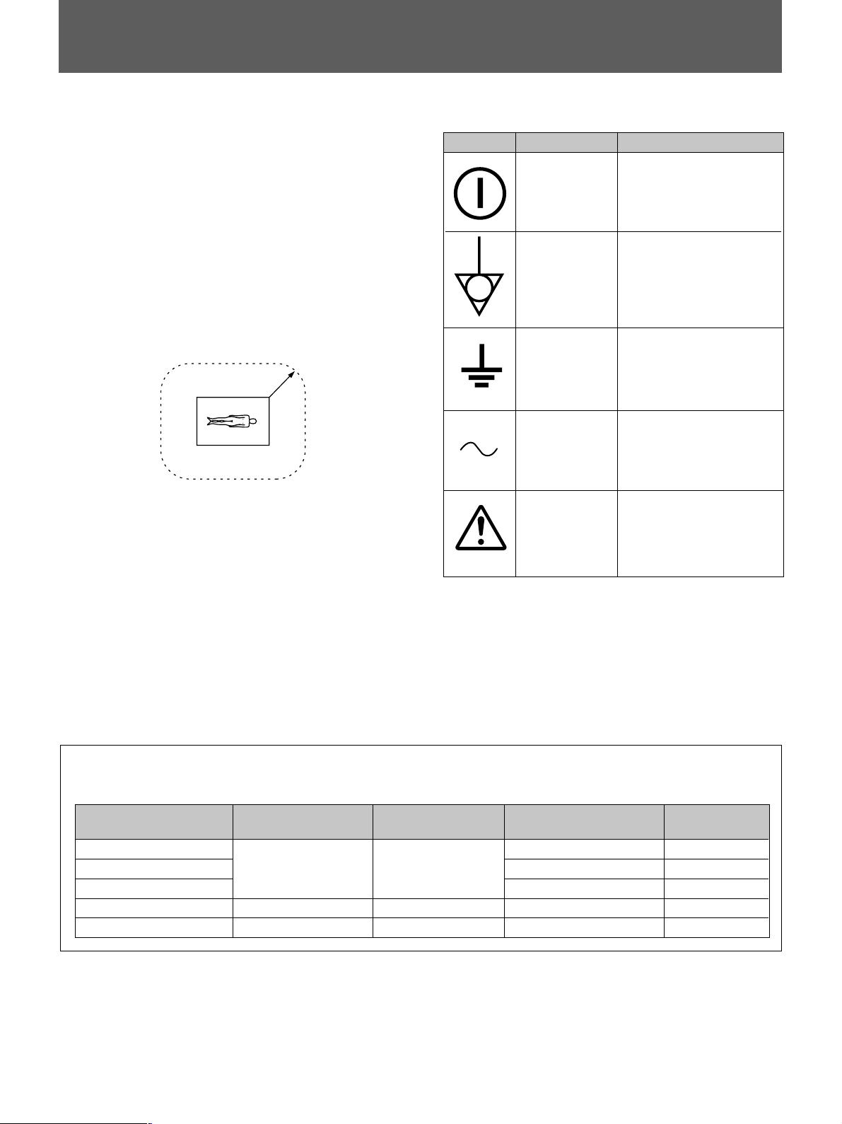
Symbols on the unit
Symbol This symbol indicates
Location
Front panel
Rear panel
Rear panel
Rear panel
Rear panel
Main power switch.
Press to turn the monitor
on or off.
The equipotential terminal
which brings the various
parts of a system to the
same potential.
Functional earth terminal
Alternating current
Attention, consult
ACCOMPANYING
DOCUMENTS
4. The operator should take precautions to avoid touching
the rear panel input and output circuitry and the patient
at the same time.
5. Model PVM-14M2MDU/14M2MDE/14M2MDA/
20M2MDU/20M2MDE/20M2MDA is a video monitor
intended for use in a medical environment to display
video pictures from cameras or other video system.
Warning on power connection
Use a proper power cord for your local power supply.
United State Canada Continental Europe Japan
Plug type HOSPITAL GRADE HOSPITAL GRADE LP-34A VM1050
Female end E41395 LL33182 LS-60 VM1010
Cord type E41395-A LL76662 H05VV-F PVCTF
Minimum cord set rating 10A/125V 10A/125V 10A/250V 12A/125V
Safety approval UL CSA VDE DENTORI
22

Table of contents
Precautions
Precautions ....................................................................... 23
Features............................................................................. 24
Location and Function of Parts and Controls ................... 25
Front Panel...................................................................... 25
Rear Panel....................................................................... 27
Using On-Screen Menus................................................... 29
Power Sources .................................................................. 33
Attaching the Side Covers ................................................ 34
Attaching the Control Panel Cover................................... 34
Specifications ................................................................... 35
On safety
• Operate the unit on 100 – 240 V AC only.
• The nameplate indicating operating voltage, power
consumption, etc. is located on the rear.
• Should any solid object or liquid fall into the cabinet,
unplug the unit and have it checked by qualified
personnel before operating it any further.
• Unplug the unit from the wall outlet if it is not to be used
for several days or more.
• To disconnect the AC power cord, pull it out by grasping
the plug. Never pull the cord itself.
• The socket-outlet shall be installed near the equipment
and shall be easily accessible.
On installation
• Allow adequate air circulation to prevent internal heat
build-up.
Do not place the unit on surfaces (rugs, blankets, etc.) or
near materials (curtains, draperies) that may block the
ventilation holes.
• Do not install the unit in a location near heat sources such
as radiators or air ducts, or in a place subject to direct
sunlight, excessive dust, mechanical vibration or shock.
On cleaning
To keep the unit looking brand-new, periodically clean it
with a mild detergent solution. Never use strong solvents
such as thinner or benzine, or abrasive cleansers since they
will damage the cabinet. As a safety precaution, unplug the
unit before cleaning it.
On repacking
Do not throw away the carton and packing materials. They
make an ideal container which to transport the unit.
If you have any questions about this unit, contact your
authorized Sony dealer.
23
Features
Picture
Trinitron1) picture tube
Trinitron tube provides a high resolution picture. Horizontal
resolution is more than 600 TV lines at the center of the
picture.
Comb filter
When NTSC video signals are received, a comb filter
activates to increase the resolution, resulting in fine picture
detail without color spill or color noise.
Beam current feedback circuit
The built-in beam current feedback circuit assures stable
white balance.
Inputs
Two color systems available
The monitor can display PAL, and NTSC signals. The
appropriate color system is selected automatically.
Analog RGB/component input connectors
Analog RGB or component (Y, R-Y and B-Y) signals from
video equipment can be input through these connectors.
Press the RGB/COMPONENT A/B select button on the
front panel and select RGB or component signals from the
on-screen menu.
Y/C input connector (S input connector)
The video signal, split into the chrominance signal (C) and
the luminance signal (Y), can be input through this
connector, eliminating the interference between the two
signals, which tends to occur in a composite video signal,
assuring video quality.
External sync input connectors
When the external RGB or component signal is input and
sync signal is set to external in the on-screen menu, the
monitor can be operated on the sync signal supplied from
an external sync generator.
Automatic termination
(only terminals with the mark)
The BNC input connectors on the rear panel are terminated
at 75 ohms inside, when no cable is connected to the loopthrough output connectors. When a cable is connected to an
output connector, the 75-ohm termination is automatically
released.
Functions
On-screen menus
You can set color temperature, CHROMA SET UP, and
other settings by using the on-screen menus.
Overscan mode
The display size is enlarged by approximately 20% and the
center part of the screen is easier to watch.
Underscan mode
The signal normally scanned outside of the screen can be
monitored in the underscan mode.
Note
When the monitor is in the underscan mode, the dark RGB
scanning lines may appear on the top edge of the screen.
These are caused by an internal test signal, rather than the
input signal.
Split function
The display splits into two parts (upper and lower). The
upper part of the screen monitors the signal fed through the
RGB/COMPONENT A input connectors and lower part of
the screen monitors the signal fed through the RGB/
COMPONENT B input connectors. You can compare the
two screens.
Auto/manual degaussing
Degaussing of the screen can be performed automatically
when the power is turned on, or manually by pressing the
DEGAUSS button.
Five menu languages
You can select the language used for on-screen menus from
the five languages.
Side cover(s) and control panel cover
The side covers that protect the ventilation holes from
splashes (of medicines, etc.) as much as possible and a
control panel cover that protects the control buttons on the
front panel from undesired touching are supplied.
EIA 19-inch rack mount kit available
Use a suitable kit when rack mounting.
Europe MB-502C (14-inches) /
SLR-103C (20-inches)
Any other area MB-502B (14-inches) /
SLR-103A (20-inches)
..........................................................................................................................................................................................................
1) Trinitron is a registered trademark of Sony Corporation.
24

Location and Function of P arts and Controls
Front Panel
RESET
RGB/COMPONENT
A
B
UNDER
OVER
SCAN
SCAN
SPLIT
MENU
EXIT
SELECT
ENTER
LINE
AB
DEGAUSS
1 Tally indicator
This indicator lights up. The tally control connection is
needed.
For the pin assignment, see “Specifications” on page 37.
2 U POWER switch and indicator
Depress to turn the monitor on. The indicator will light
up in green. To turn the power off, press this again.
3 REMOTE indicator
This indicator lights up in the conditions below:
— When PRESET is set to ON in the menu.
— When REMOTE (RS-232C) is set to REMOTE
ONLY or REMOTE & LOCAL in the menu, or
— When REMOTE ON is set via the REMOTE 1
terminal.
4 Á VOLUME control
Turn this control clockwise or counterclockwise to
obtain the desired volume.
APERTURE
MIN
MAX
POWER
REMOTE
– +
MIN
CONTRAST
PHASECHROMABRIGHT
MAX
PUR GRN MIN MAX MIN MAX
VOLUME
7 ¯ CHROMA (chrominance) control
Turn clockwise to make the color intensity stronger and
counterclockwise to make it weaker.
8 ¨ BRIGHT (brightness) control
Turn clockwise for more brightness and
counterclockwise for less.
9 ΠAPERTURE control
Turn clockwise for more sharpness and
counterclockwise for less.
When the control is set to MIN, the picture becomes flat
without need for corrections.
Note
The APERTURE, CHROMA, PHASE control settings
have no effect on the pictures of RGB signals.
The PHASE control setting has no effect on the pictures
of component signals.
5 > CONTRAST control
Turn clockwise to make the contrast stronger and
counterclockwise to make it weaker.
6 PHASE control
This control is effective only for the NTSC color
system. Turn clockwise to make the skin tones greenish
and counterclockwise to make them purplish.
!º MENU (EXIT) button
Press to make the menu appear.
Press to return to the previous screen in the menu.
!¡ ENTER (SELECT) button
Press to decide a selected item in the menu.
25

Location and Function of Parts and Controls
!™ > (+)/ . (–) buttons
Press to move the cursor (z) or adjust selected value in
the menus.
!£ OVERSCAN button
Press (light on) for overscanning. The display size is
extended by approximately 20% so that the center of
screen is easier to watch. By pressing the button again,
the display returns to the normal size (light off).
!¢ UNDERSCAN button
Press (light on) for underscanning. The display size is
reduced by approximately 5% so that four corners of the
raster are visible. By pressing the button again, the
display returns to the normal size (light off).
!∞ RESET button
During menu adjustments, press to reset the setting in
the menu.
!§ DEGAUSS button
Press this button momentarily. The screen will be
demagnetized.
Wait for 10 minutes or more before activating this
button again.
c
Note
The picture rolls vertically while the screen is being
demagnetized.
!¶ LINE A/B select buttons
Press to select a signal (light on).
A:Press to monitor the signal fed through the LINE A
input connectors.
B: Press to monitor the signal fed through the LINE B
input connectors.
!• RGB/COMPONENT A/B select buttons
Press to select a signal (light on).
A:Press to monitor the signal fed through the RGB/
COMPONENT A input connectors.
B: Press to monitor the signal fed through the RGB/
COMPONENT B input connectors.
!ª SPLIT button
When you select RGB signals fed through the RGB/
COMPONENT A and RGB/COMPONENT B input
connectors, press this button (light on) to split the
display into two parts (upper and lower), and monitor
the both RGB signals simultaneously.
Note
Make sure the signals fed through the RGB/
COMPONENT A and RGB/COMPONENT B input
connectors are synchronized.
26

Rear Panel
c
AC IN
Note
Before connecting the video equipment, see “Important
safeguards/notices for use in the medical environments” on
page 22.
VIDEO AUDIO
R/R–Y G/Y B/B–Y
A
IN
R/R–Y
B
IN
LINE A
OUT IN OUT IN OUT IN OUT IN OUT
G/Y B/B–Y
IN IN
RGB/COMPONENT
1 AC IN socket
Connect the supplied AC power cord to this socket.
“⁄” means Alternating Current.
2 LINE A connectors
Line input connectors for the composite video and audio
signals and their loop-through output connectors.
To monitor the input signal fed through these
connectors, press LINE A select button (light on) on the
front panel.
VIDEO IN (BNC)
Connect to the video output connector of a video
equipment, such as a VTR or a color video camera. For
a loop-through connection, connect to the video output
connector of another monitor.
VIDEO OUT (BNC)
Loop-through output of the VIDEO IN connector.
Connect to the video input connector for a VTR or
another monitor.
When the cable is connected to this connector, the
75-ohms termination of the input is automatically
released, and the signal input to the VIDEO IN
connector is output from this connector.
AUDIO IN (phono jack)
Connect to the audio output connector of a VTR or to a
microphone through a suitable microphone amplifier.
For a loop-through connection, connect to the audio
output connector of another monitor.
AUDIO OUT (phono jack)
Loop-through output of the AUDIO IN connector.
Connect to the audio input connector of a VTR or
another monitor.
IN OUTIN OUT
EXT SYNC
AUDIO
IN IN
Y/C
IN OUT
(The mark indicates automatic termination.)
LINE B
AUDIO
AUDIO
IN OUT
EXT SYNC
8V/0.8A
REMOTE
REMOTE 1DC OUTRS-232C
3 LINE B connectors
Separated Y/C input connectors, audio input
connectors, and corresponding loop-through output
connectors.
To monitor the input signal fed through these
connectors, press LINE B select button (light on) on the
front panel.
Y/C IN (4-pin mini DIN)
Connect to the Y/C separate output connector of a VTR,
video camera or other video equipment.
Y/C OUT (4-pin mini DIN)
Loop-through output of the Y/C IN connector. Connect
to the Y/C separate input connector of a VTR or another
monitor.
When the cable is connected to this connector, the
75-ohms termination of the input is automatically
released, and the signal input to the Y/C IN connector is
output from this connector.
AUDIO IN (phono jack)
Connect to the audio output connector of a VTR or to a
microphone through a suitable microphone amplifier.
For a loop-through connection, connect to the audio
output connector of another monitor.
AUDIO OUT (phono jack)
Loop-through output of the AUDIO IN connector.
Connect to the audio input connector of a VTR or
another monitor.
27

Location and Function of Parts and Controls
4 RGB/COMPONENT A connectors
RGB signal or component signal input connectors and
their loop-through output connectors.
To monitor the input signal fed through these
connectors, press the RGB/COMPONENT A select
button (light on) on the front panel.
Then select one out of four items in the RGB A
SYSTEM menu to set the RGB or COMP (component)
signal and the INT SYNC (internal sync) or EXT SYNC
(external sync) signal.
For the operation through the menus, see pages 29 to
32.
R/R-Y IN, G/Y IN, B/B-Y IN (BNC)
When “RGB-INT SYNC” or “COMP-INT SYNC” is
selected in the RGB A SYSTEM menu, the monitor
operates on the sync signal from the G/Y channel.
To monitor the RGB signal
Connect to the analog RGB signal output connectors of
a video camera.
To monitor the component signal
Connect to the R-Y/Y/B-Y component signal output
connectors of a Sony Betacam equipment.
R/R-Y OUT, G/Y OUT, B/B-Y OUT (BNC)
Loop-through outputs of the R/R-Y IN, G/Y IN, B/B-Y
IN connectors.
When the cables are connected to these connectors, the
75-ohms termination of the inputs is automatically
released, and the signal inputs to the R/R-Y IN, G/Y IN,
B/B-Y IN connectors are output from these connectors.
To output the analog RGB signal
Connect to the analog RGB signal input connectors of a
video printer or another monitor.
To output the component signal
Connect to the R-Y/Y/B-Y component signal input
connectors of a Sony Betacam equipment.
AUDIO IN (phono jack)
Connect to the audio output connector of video
equipment when the analog RGB or component signal is
input.
AUDIO OUT (phono jack)
Loop-through outputs of the AUDIO IN connector.
EXT SYNC (external sync) IN (BNC)
When this monitor operates on an external sync signal,
connect the signal from a sync generator to this
connector.
To use the sync signal fed through this connector, select
“RGB-EXT SYNC” or “COMP-EXT SYNC” in the
RGB A SYSTEM menu.
EXT SYNC (external sync) OUT (BNC)
Loop-through output of the EXT SYNC IN connector.
Connect to the external sync input connector of video
equipment to be synchronized with this monitor.
When the cable is connected to this connector, the
75-ohms termination of the input is released, and the
signal input to the EXT SYNC IN connector is output
from this connector.
5 Ground (1/Y) terminal
Connect a GND cable.
6 RGB/COMPONENT B connectors
RGB signal or component signal input connectors.
To monitor the input signal fed through these
connectors, press the RGB/COMPONENT B select
button (light on) on the front panel.
Then select one out of four items in the RGB B
SYSTEM menu to set the RGB or COMP (component)
signal and the INT SYNC (internal sync) or EXT SYNC
(external sync) signal.
For the operation through the menus, see pages 29 to
32.
R/R-Y IN, G/Y IN, B/B-Y IN (BNC)
When “RGB-INT SYNC” or “COMP-INT SYNC” is
selected in the RGB B SYSTEM menu, the monitor
operates on the sync signal from the G/Y channel.
To monitor the RGB signal
Connect to the analog RGB signal output connectors of
a video camera.
To monitor the component signal
Connect to the R-Y/Y/B-Y component signal output
connectors of a Sony Betacam equipment.
AUDIO IN (phono jack)
Connect to the audio output connector of video
equipment when the analog RGB or component signal is
input.
EXT SYNC (external sync) IN (BNC)
When this monitor operates on an external sync signal,
connect the signal from a sync generator to this
connector.
To use the sync signal fed through this connector, select
“RGB -EXT SYNC” or “COMP-EXT SYNC” in the
RGB B SYSTEM menu.
7 REMOTE connectors
RS-232C (D-sub 9-pin)
Connect to the RS-232C control connector of other
equipment. You can operate the monitor with the
control command from the equipment.
For the details, see the supplied Interface Manual for
Programmers.
REMOTE 1 (8-pin mini DIN)
Connect to the tally output connector of a control
console, effects, etc. The tally indicator on the front
panel will be turned on and off by the connected
equipment.
You can also connect a remote controller using this
connector.
For the pin assignments of these connectors, see
“Specifications” on page 37.
DC OUT 8V/0.8A connector
You can use this connector as a power source for the
other equipment.
DC 8V/0.8A is output.
28
Using On-Screen Menus
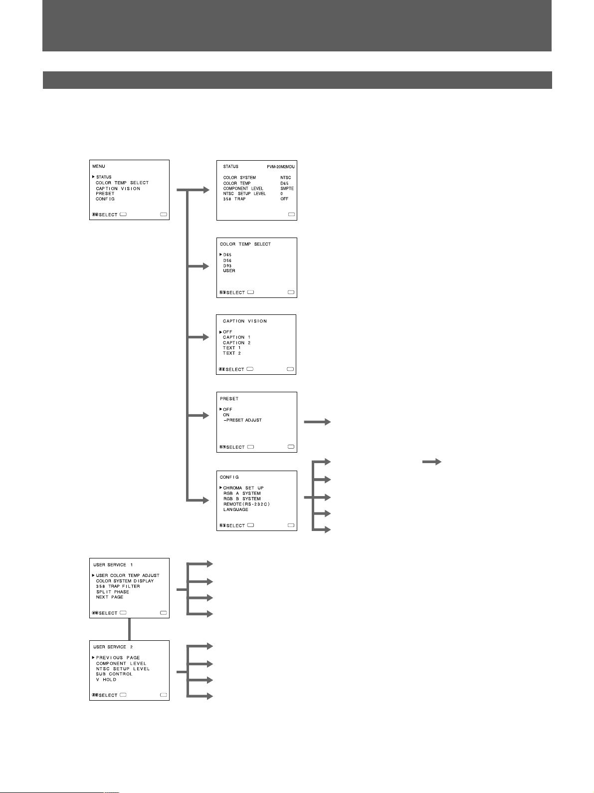
Menu Configuration
The flow chart shows the different levels of on-screen
menus that you can use to make various adjustments and
settings.
For details of each menu, see pages 30 to 32.
1 Main menu
2 STATUS menu
c
ENTER
MENU
3 COLOR TEMP SELECT menu
ENTER
4 CAPTION VISION menu
ENTER
5 PRESET menu
ENTER
6 CONFIG menu
ENTER
MENU
MENU
1)
MENU
7 PRESET ADJUST screen
MENU
8 CHROMA SET UP menu
9 RGB A SYSTEM menu
!º RGB B SYSTEM menu
!¡ REMOTE (RS-232C) menu
MENU
!™ LANGUAGE menu
!£ AUTO ADJUST screen
User Service Mode
!¢ USER COLOR TEMP ADJUST menu
!∞ COLOR SYSTEM DISPLAY menu
!§ 358 TRAP FILTER menu
ENTER
ENTER
MENU
MENU
!¶ SPLIT PHASE menu
!• COMPONENT LEVEL menu
!ª NTSC SETUP LEVEL menu
@º SUB CONTROL screen
@¡ V HOLD screen
..........................................................................................................................................................................................................
1) CAPTION VISION in the Main menu is designed for an exclusive use with the PVM-20M2MDU and 14M2MDU
models.
29
A
M
Using On-Screen Menus
c
c
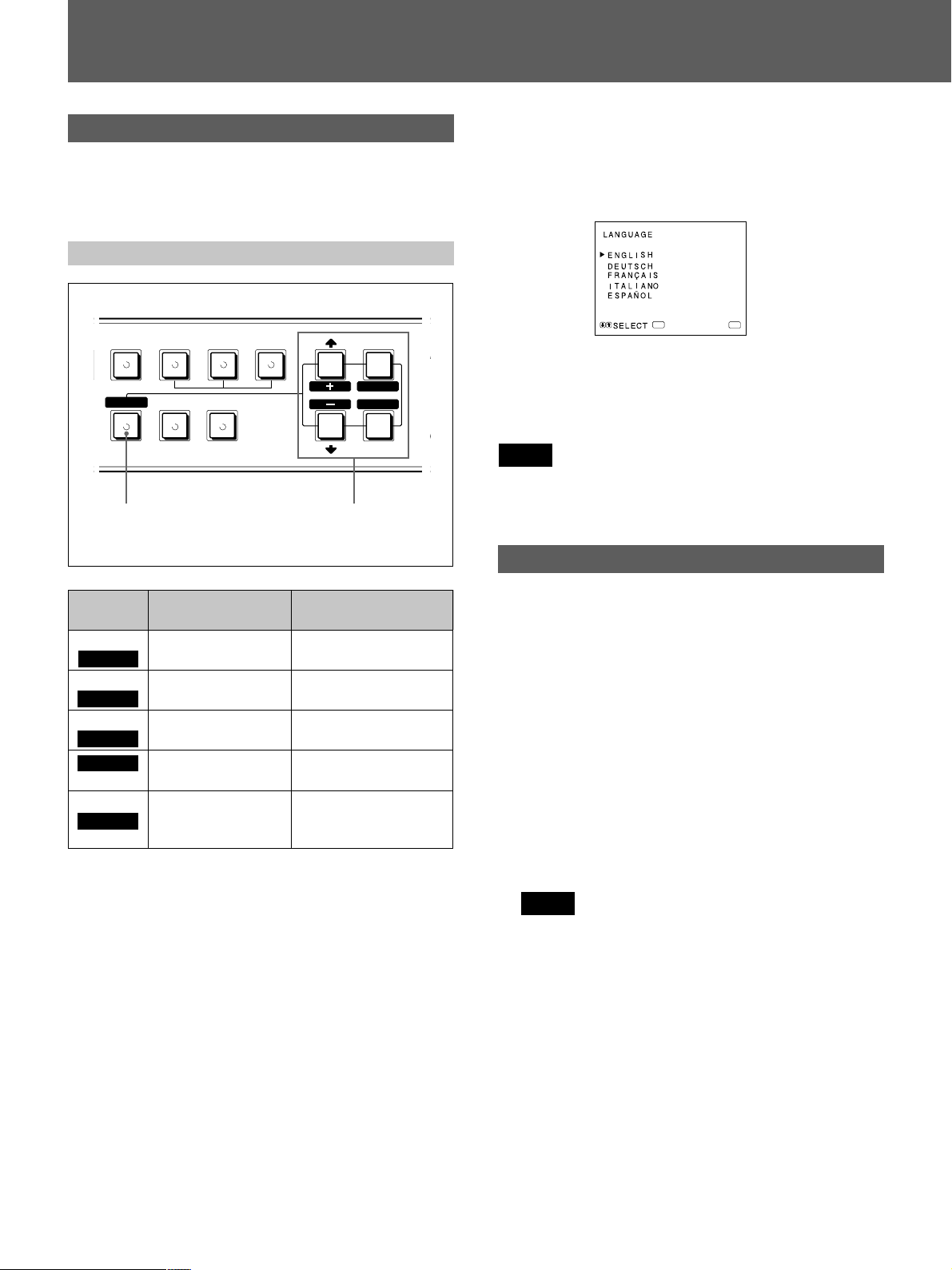
Operating through Menus
There are five buttons for menu operations on the front
panel of the monitor. To display the main menu, first press
MENU (EXIT). The buttons you can use appear at the
bottom of the menu screen.
Functions of the buttons
RGB/COMPONENT
RESET
BLUE
ONLY
RESET
button
ABB SPLIT
UNDER
SCAN
OVER
SCAN
MENU
EXIT
SELECT
ENTER
Buttons for
menu
operations
For PVM-14M2MDE/14M2MDA/20M2MDE/
20M2MDA:
For the first time when the monitor is turned on, the
LANGUAGE menu (!™) will appear on the screen.
So, select the language you want to use.
ENTER
MENU
1 Move the cursor (z) to the desired language by
pressing the ./– or >/+ button.
2 Press the MENU(EXIT) button.
Note
Unless you press the MENU(EXIT) button in the procedure
above, the LANGUAGE menu will always appear
whenever you turn on the monitor.
The Contents of Menu Items
Button
MENU
EXIT
ENTER
SELECT
>
+
–
.
RESET
To select menu
item
return to the
previous menu.
decide a selected
item.
move the cursor (z)
upwards.
move the cursor (z)
downwards.
To adjust selected
menu item
return to the previous
menu.
select an item.
increase selected
value.
decrease selected
value.
reset current
adjustment value to the
factory setting.
(The above items in white type correspond to the marks in
the menu.)
The following sentences show the details of each menu
items.
[ ] indicates the factory setting position.
1 Main menu
Select an item and press the ENTER (SELECT) button
to go to the following menu.
2 STATUS menu
Shows the current settings.
3 COLOR TEMP SELECT menu
Select the color temperature from among D65, D56,
D93 and USER. USER is set to D65 in the factory
setting. You can adjust or change the color temperature
in USER mode (a measuring instrument is needed).
[D65]
Note
The color temperature of the USER mode can be
adjusted in the range from 3200K to 10000K.
You can adjust the color temperature of the USER mode
in the USER COLOR TEMP ADJUST menu (!¢) of
the user service mode.
For the details, see USER COLOR TEMP ADJUST
menu (!¢) on page 31.
30
4 CAPTION VISION menu
This menu is provided only for PVM-20M2MDU/
14M2MDU.
The monitor can display the signal with Caption Vision.
To display it, select the caption type in this menu.
[OFF]
 Loading...