

Page 1
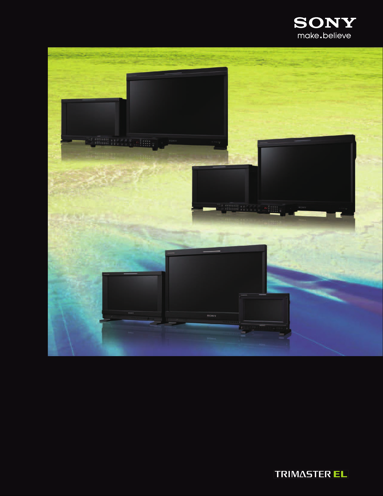
BVM-E / BVM-F / PVM Series
TRIMASTER EL OLED Monitors
BVM-E250 / BVM-E170
Professional OLED Master Monitor
BVM-F250 / BVM-F170
Professional OLED Master Monitor
PVM-2541 / PVM-1741 / PVM-740
Professional OLED Picture Monitor
Page 2
Sony OLED – Re-defining
the Master Monitor and Picture Monitor
Sony is proud to introduce its latest lineup of OLED (organic light emitting diode) monitors.
These include three separate series to fit most any need in your production process.
The BVM E series offers performance and features for work with extremely critical
technical needs. The BVM F series offers features and performance for production and post
production applications where content will deliver to a broadcaster, and the PVM series
offers features and performance for general usages.
Only Sony has the capability to develop products such as these, as the company builds on
over 30 years of CRT and LCD master monitor experience in the production industry, and
has created its own sophisticated OLED display devices and signal processing engines.
Sony has developed these 24.5-inch and 16.5-inch professional OLED display panels for
critical professional use. The OLED is a self-emitting device, and can deliver deep blacks,
high-contrast, accurate color reproduction, and quick response with virtually no motion blur.
And yet it features a wide color gamut, meeting ITU-R BT.709, EBU, and SMPTE-C broadcast
standards, and conforming to the wider DCI-P3 color gamut.*
3
Furthermore, the newly developed OLED processor with cutting-edge technology offers
quality consistency, superb uniformity, and long-term reliability.
Sony optimizes the potential of the OLED panel using unique Super Top Emission OLED
technology along with the dedicated OLED processor. The combination of these
technological developments elevate the BVM-E, BVM-F, and PVM Series to a new level of
next-generation master monitors and picture monitors, re-setting the industry’s ultimate
reference point.
With Sony OLED fully unleashed, Sony starts a new and important chapter in professional
monitor history.
*1 24.5-inch (623.4 mm), measured diagonally.
*2 16.5-inch (419.7 mm), measured diagonally.
*3 The color gamut described in SMPTE RP 431-2-2007. The chromaticity of the green-red region is not covered in full. BVM-E Series only.
2
Page 3
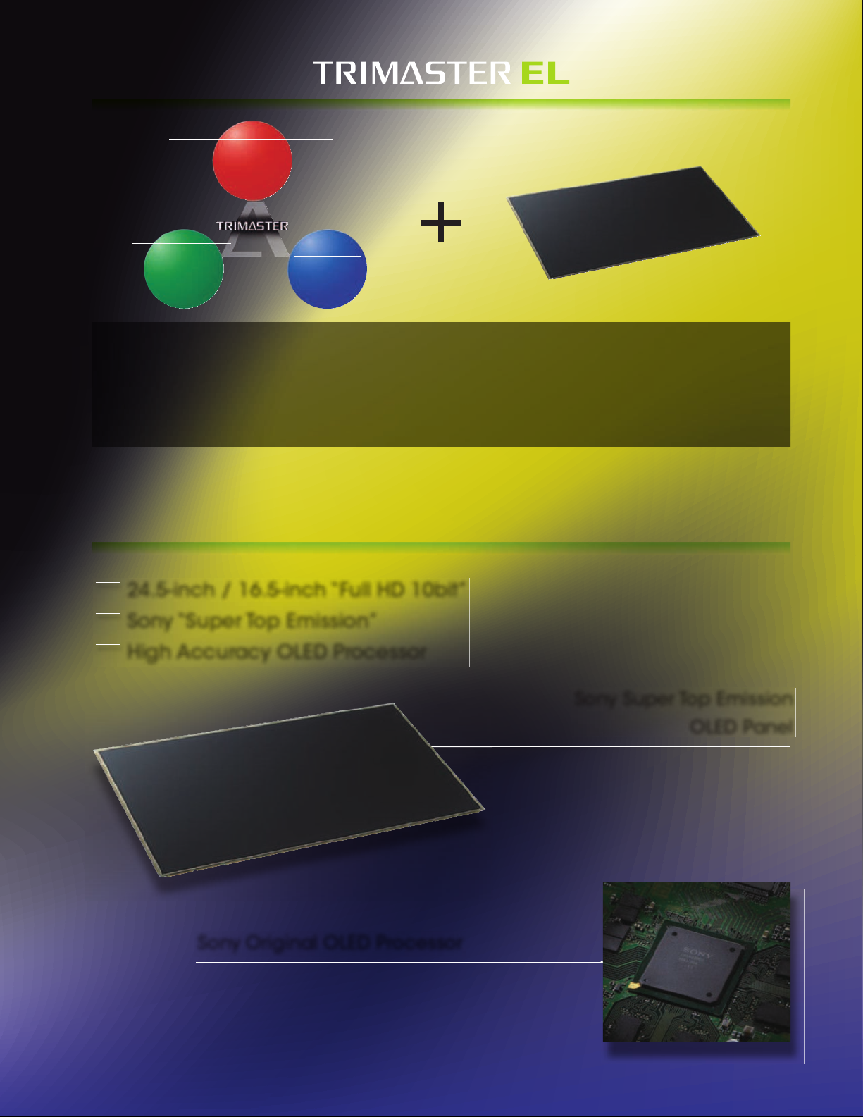
Accurate Color Reproduction
• Color Management System
• Multiple Color Gamuts
• Digital Uniformity
Sony OLED Panel
Precision Imaging
•High Resolution & High Color
Depth Panel
•High Motion Picture Processing
•Accurate Pixel Mapping
TRIMASTER™ Technology is a design architecture used to elicit the full performance capabilities of
professional flat-panel displays. It comprises the core technologies that enable the highest level of color
accuracy, precision imaging, and picture-quality consistency.
EL (Electro-Luminescence) is an ideal self-emission display device with a wide dynamic range and high
picture accuracy. By refining TRIMASTER technology with the new EL device, Sony effectively boosts the
performance expectations of the professional industry.
Quality Picture
Consistency
•Accurate Signal Processing
•Precise Calibration System
•Color Feedback System
Sony Unique OLED Technology
24.5-inch / 16.5-inch “Full HD 10bit”
Sony “Super Top Emission”
High Accuracy OLED Processor
Sony Original OLED Processor
• Designed specifically for Sony OLED panel
• Accurate gamma control of extreme black details
• Superb picture uniformity and reliability
Sony Super Top Emission
OLED Panel
• Accurate black reproduction
• Accurate color reproduction
• Wide dynamic range
• Fast response time
3
Page 4
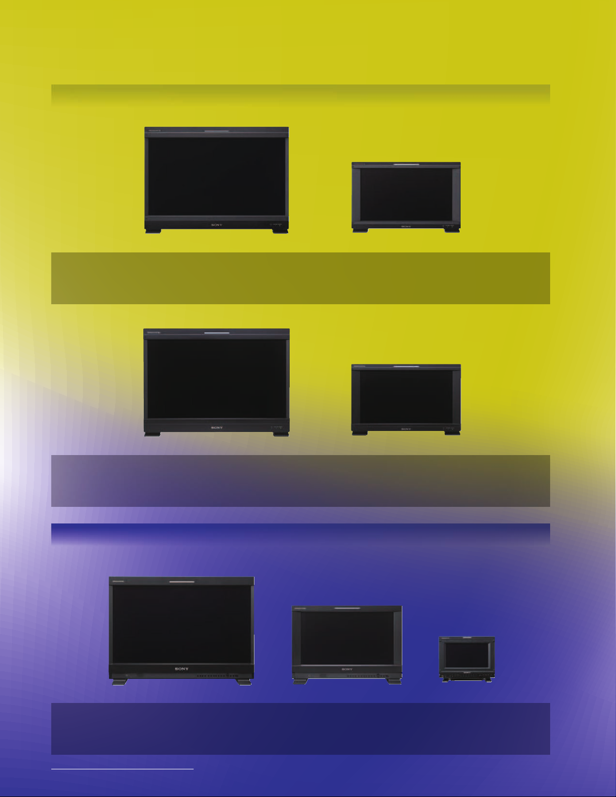
BVM-E Series
TRIMASTER EL OLED Master Monitor
BVM-E250
The groundbreaking BVM-E250 and BVM-E170 are top of the line Sony OLED reference monitors,
incorporating leading-edge technologies to bring out the full performance capabilities required for
critical picture evaluation, where accuracy, stability, and consistency are everything.
BVM-E170
BVM-F Series
BVM-F250
The BVM-F250 and BVM-F170 inherit the same technology and performance of BVM-E Series master
monitors, and are optimized for TV production and broadcasting applications.
BVM-F170
TRIMASTER EL OLED Picture Monitor
PVM Series
PVM-2541
The PVM-2541 and PVM-1741, as well as the PVM-740, are all-in-one OLED picture monitors for a wide
range of applications, delivering unparalleled picture quality with the performance features and
functions found in more expensive monitors, all contained in a compact, robust, one piece design.
4
PVM-1741
PVM-740
Page 5
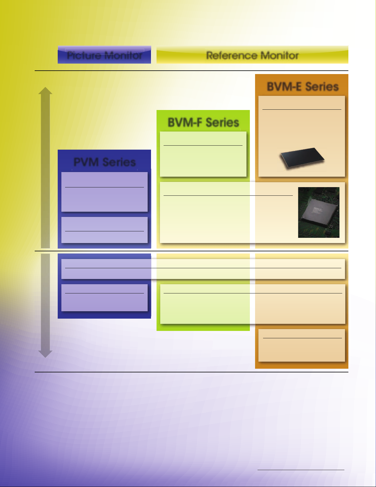
Picture Monitor
Quality / Performance
PVM Series
Standard Panel
• Stunning OLED performance
• Full HD (1920 x 1080) *
• RGB 10bit Driver
Standard Engine
• 10-bit engine
1
Reference Monitor
BVM-E Series
BVM E Panel
Designed as the highest Sony
BVM-F Series
BVM F Panel
Strictly controlled tolerance in
addition to the standard panel
performance.
Professional Display Engine
• 12-bit engine
• Accurate gamma control of extreme black details
• Cutting-edge I/P conversion with extremely low
process delay
• Sophisticated non-linear cubic conversion color
management
performance panel.
Used for the most critical
picture evaluation needs.
• 3G-SDI (x 2)*1 • RGB 4:4:4*1 • HDMI • Auto White Adjustment*2 • Time code*1 • Audio Level Meter*3 • DC operation (17”)
• Waveform
• Audio
Functionality
PVM Functions
Standard Features
BVM Advanced Functions
• Option port x 4 (BKM x 6 selection)
• Dual Link*
• DisplayPort (x1)
• Interlace display
3
• Pixel zoom
• HD frame capture
• 24P/PsF@72 Hz display
• 3D analysis*
Digital Cinema Features
• 2K (2048 x 1080 RGB/XYZ) input
• ASC CDL*
• P&P (Wipe, Butterfly, Blending)
*1 Not applicable for PVM-740.
*2 Supported by firmware V1.1 or later.
*3 Option board required for BVM.
3
2
• User LUT*
2
5
Page 6
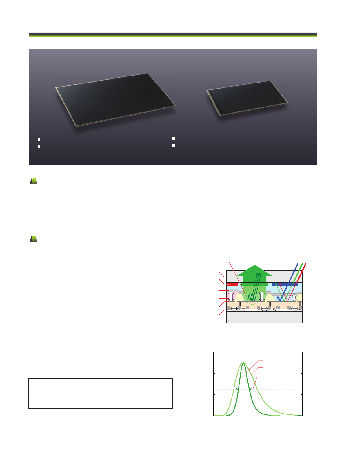
Advantages of the Sony OLED Technology
Advantages of Sony’s OLED Technology
Sony’s OLED – RGB 10-bit, Full HD
Sony’s unique Super Top Emission technology
Deep black with high dynamic range
* 623.4 mm, and 419.7 mm (respectively), viewable area measured diagonally.
Quick response with virtually no motion blur
Wide color gamut and accurate color reproduction
Micro-cavity Structure
Optical Resonance
(Multiple Reection Interference Effect)
Glass Substrate
Glass Substrate
Color Filter
Emission Layer
Anode
TFT
Semi-transparent
Cathode
Wavelength(nm)
Intensity(A.U.)
0.0
0.2
0.4
0.6
0.8
1.0
1.2
400 500 600 700 800
Green Light Emitting Spectrum
With cavity
Without cavity
Reduces
unnecessary
optical ingredients
Sony’s OLED – Self-emitting Display Device
Sony’s OLED creates light by recombining an electron and a hole within certain organic materials. The process of emitting light
is extremely efcient when compared to other technologies currently used for display.
Its organic materials react to the control of the electrical current immediately, and do not emit light in the absence of an
electrical current. In this way, the OLED display panel features superb black performance and quick response to fast-motion
pictures. In addition, Sony’s OLED display panel delivers a wider color gamut.
Super Top Emission Technology
Sony’s Super Top Emission OLED panel is designed to deliver
light emission with the TFT layer on the rear side of the panel.
Therefore, the top emission structure offers more efcient light
emission than is typical with bottom emission structures where
TFT layers are placed on the front side of the panel, limiting
the light-emission aperture.
This Super Top Emission technology has a micro-cavity
structure which incorporates color lters. This cavity structure
uses an optical resonance effect to enhance color purity
and improve light-emission efciency, which gives the monitor
very accurate primary colors. In addition, the color lter of
each RGB also enhances the color purity of emitted light, and
reduces ambient light reection.
Sony’s Super Top Emission OLED panel is completely sealed
by a glass substrate, and the electroluminescent layer is fully
isolated from outside air and moisture. This contributes to
stability and reliability.
24.5” panel* 16.5” panel*
Sony OLED – RGB 10-bit, Full HD
24.5” panel* 16.5” panel*
Sony unique Super Top Emission technology
Deep blacks with wide dynamic range
* 623.4 mm, and 419.7 mm (respectively), measured diagonally.
Sony OLED – Self-emitting Display Device
Sony OLED creates light by recombining an electron and a hole within certain organic materials. The process of emitting light is
extremely efficient when compared to other technologies currently used for display.
Its organic materials react to the control of the electrical current immediately, and do not emit light in the absence of an
electrical current. In this way, the OLED display panel features superb black performance and quick response to fast-motion
pictures. In addition, the Sony OLED display panel delivers a wider color gamut.
Super Top Emission Technology
The Sony Super Top Emission OLED panel is designed to
deliver light emission with the TFT layer on the rear side of
the panel. Therefore, the top emission structure offers more
efficient light emission than is typical with bottom emission
structures where TFT layers are placed on the front side of the
panel, limiting the light-emission aperture.
This Super Top Emission technology has a micro-cavity
structure which incorporates color filters. This cavity structure
uses an optical resonance effect to enhance color purity and
improve light-emission efficiency. In addition, the color filter of
each RGB also enhances the color purity of emitted light, and
reduces ambient light reflection.
The Sony Super Top Emission OLED panel is completely sealed
by a glass substrate, and the electroluminescent layer is fully
isolated from outside air and moisture. This contributes to
stability and reliability.
The diagram on the right shows how the Sony micro cavity
structure takes out of band light that doesn't contribute to the
correct colors and combines it with the in-band color so that
a more saturated and accurate color can be displayed.
Quick response with virtually no motion blur
Wide color gamut and accurate color reproduction
Optical Resonance
(Multiple Reection Interference Effect)
Glass Substrate
Color Filter
Semi-transparent
Cathode
Emission Layer
Anode
Glass Substrate
1.2
1.0
0.8
0.6
0.4
Intensity(A.U.)
0.2
0.0
TFT
Micro-cavity Structure
Green Light Emitting Spectrum
400 500 600 700 800
Wavelength(nm)
With cavity
Without cavity
Reduces
unnecessary
optical ingredients
6
Page 7
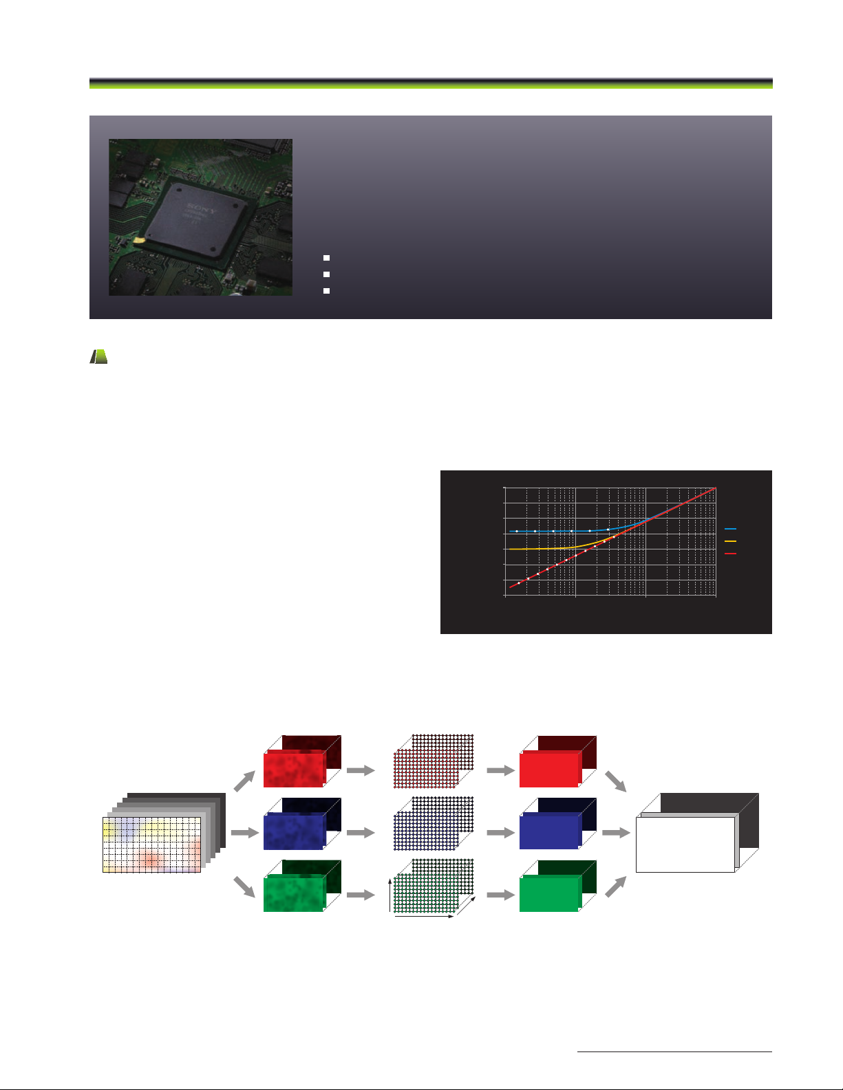
Advantages of the Sony OLED Technology
The OLED processor
– Dedicated to eliciting full performance.
Accurate signal processing across all signal levels
Accurate gamma control
Superb uniformity control
Dedicated Sony OLED Processor*
The BVM-E, BVM-F, and PVM Series of OLED monitors incorporate newly developed OLED-dedicated signal processors to elicit and
maximize OLED panel performance. This technology allows these TRIMASTER EL™ monitors to provide the level of performance
required for critical imaging. These processors accurately control gamma and uniformity, and deliver precision stability control.
* The PVM-740 is equipped with a different processing technology (ChromaTRU™).
Accurate gamma control
Since the Sony OLED panel can display a deeper black than
any other display device, the TRIMASTER EL OLED processor
controls gamma accuracy (black reproduction) by increased
signal processing bit depth.
100
]
2
10
1
BVM-L
0.1
0.01
0.001
0.0001
Luminance [cd/m
0.00001
BVM-E
Input Signal [%]
LCD
CRT
OLED
101
1000.1
Superb uniformity control
The Sony OLED processor offers superb uniformity across all signal levels at every point of the screen. At the factory, OLED-panel
uniformity is precisely measured and corrected using a proprietary RGB LUT (look-up table) adjustment system.
R-LUT
B-LUT
V position
H position
G-LUT
Level
7
Page 8
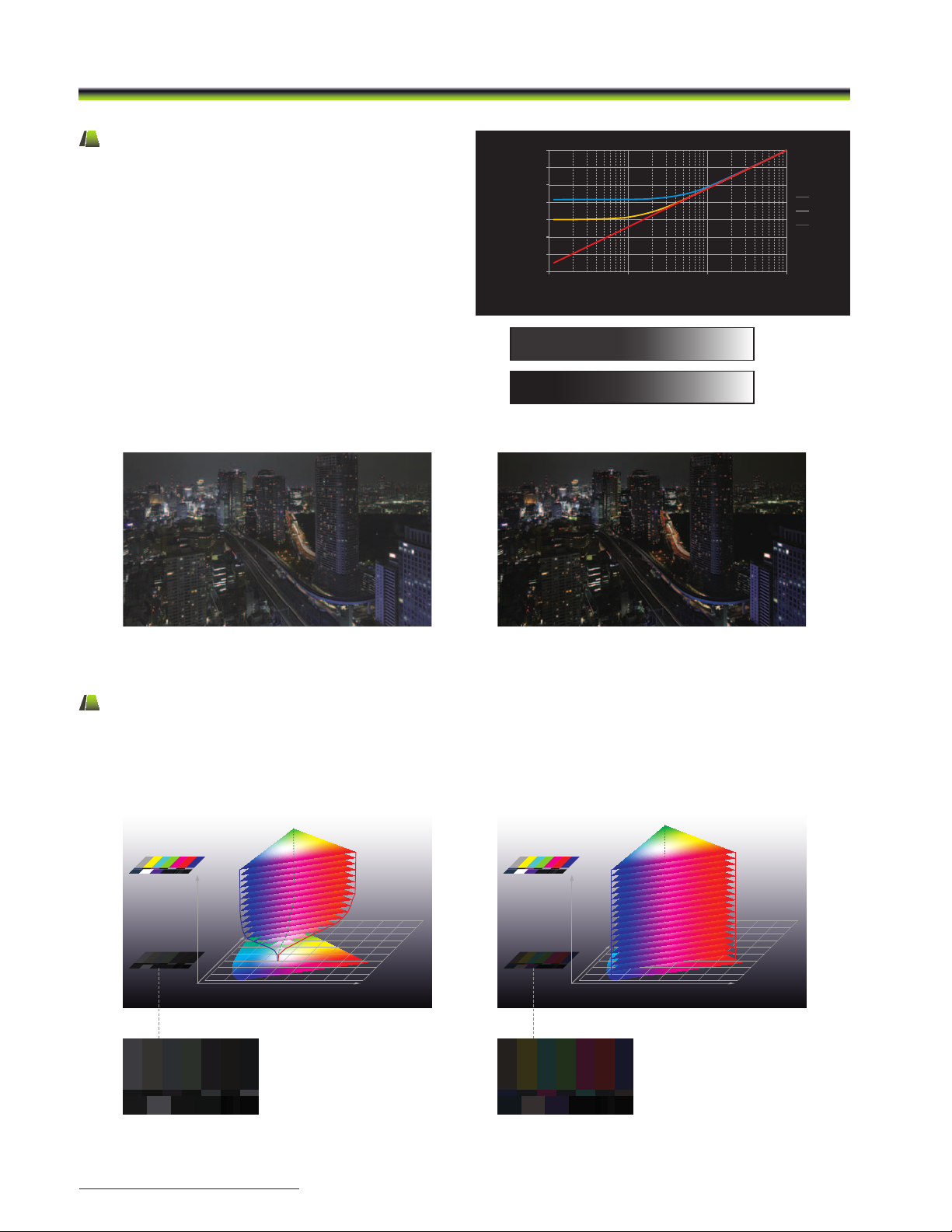
Advantages of the Sony OLED Technology
* Gray scales are simulated images.
Accurate Black Reproduction
A key advantage of the Sony OLED is the fact that each pixel
can be turned completely off. No other display technology
is able to offer this. LCD either raises black luminance due
to intrinsic light leakage, or reduces black luminance with
artificial local dimming technologies. CRT always applies a
bias voltage to place the gun at the proper operating level.
All of these display devices have some limitation in accuracy
of black reproduction. In comparison, Sony TRIMASTER EL
OLED is capable of reproducing accurate black with each
individual pixel, enabling users to evaluate each picture
image faithfully to the signal.
100
]
2
10
1
0.1
0.01
0.001
0.0001
Luminance [cd/m
0.00001
101
Input Signal [%]
Gray scale images corresponding to the input signal
LCD
CRT
OLED
1000.1
LCD
Sony OLED
LCD Sony OLED
Simulated images
Accurate Color Reproduction
Sony Super Top Emission technology not only offers a wide color gamut with its purity of the three primary colors, but also
maintains this wide color gamut throughout the entire luminance range. While all other display devices have limitations in
reproducing accurate colors, especially in the low signal levels, Sony OLED system is truly an ideal display device for picture
evaluation. With OLED, users see the details in the blacks, and see the colors as well.
0.900
0.800
0.700
0.600
0.500
0.400
0.300
0.200
0.100
0.000
0.100 0.200 0.300 0.400 0.500 0.600 0.700 0.800
LCD* Sony OLED*
0.000
0.100
0.900
0.800
0.700
0.600
0.500
0.400
0.300
0.200
0.100 0.200 0.300 0.400 0.500 0.600 0.700 0.800
8
* Color gamut images based on test results by Sony
Page 9
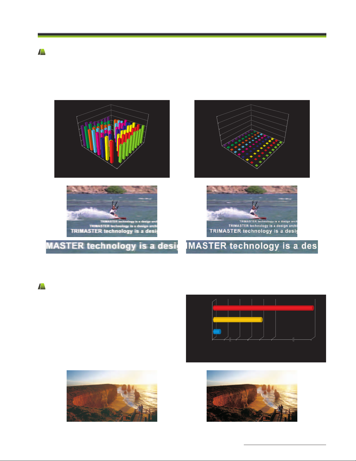
Advantages of the Sony OLED Technology
Quick Response with Virtually No Motion Blur
The Sony OLED gray-to-gray switching speed (measured in microseconds, μs) is much faster than that of the LCD (measured in
milliseconds, ms).* This fast response benefits a variety of applications and uses. For example, in sports broadcasting, when
camera pans would become blurred with an LCD, they remain sharp and clear with OLED. And with moving titles or graphics,
when text can be difficult to read on an LCD, OLED displays clear text, regardless of speed or direction.
* Test results by Sony
10.0
8.0
6.0
4.0
msec
2.0
0.0
100.0
Start Level [%]
75.0
50.0
25.0
0.0
LCD
10.0
8.0
6.0
4.0
msec
100.0
75.0
50.0
Destination
25.0
Level [%]
0.0
LCD
2.0
0.0
100.0
75.0
Start Level [%]
50.0
25.0
100.0
75.0
50.0
Destination
25.0
Level [%]
0.0
0.0
OLED
Sony OLED
Simulated images
Wide Dynamic Range
Sony OLED technology has the ability to control each
individual pixel from an absolute black to peak white. Each
pixel can display the entire dynamic range of the image with
no interference to the adjacent pixels.
LCD
Sony’s OLED
CRT
LCD
x:1
2,000
Contrast ratio
Sony OLED
50,0001 40,00030,00020,000
1,000,000
Simulated images
9
Page 10
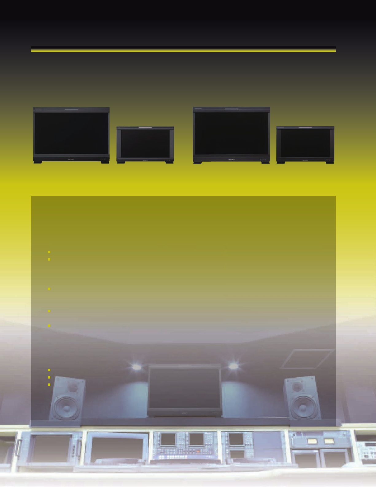
TRIMASTER EL OLED Master Monitor
For Critical Picture Evaluation
BVM-E Series BVM-F Series
BVM-E250 BVM-F250BVM-E170 BVM-F170
The groundbreaking BVM E series and BVM F series are reference monitors,
using the Sony OLED system and incorporating leading-edge technologies
to bring out the full performance capabilities required for critical picture
evaluation, where accuracy is everything.
The Sony OLED uses the Sony Super Top Emission technology with 10-bit RGB panels and OLED processing
Professional display engine
• Nonlinear Cubic Conversion color management system
• Cutting-edge interlaced to progressive conversion technology with extremely low process delay
• 12-bit output accuracy signal processing
Input versatility
• Standard Input: 3G/HD/SD-SDI (x2) (selectable input), HDMI (HDCP) (x1), DisplayPort (x1)*
• Four option slots for input expansion: Six optional BKM boards are available for different needs
Leading-edge features
• Interlace Display, HD Frame Capture, Pixel Zoom, P&P (Side-by-side, Butterfly*
Cinema features (BVM-E Series only)
• Wide color gamut: D-Cine conforming to DCI-P3, BVM Native offering the widest color gamut
• High frame rate: 24P/PsF, 2P/PsF are displayed at 72 Hz and 7 Hz respectively
• 2K Cinema formats with multiple display modes
(Full image display, or Native pixel-to-pixel display with an Image-slide function)
• ASC CDL (American Society of Cinematographers Color Decision List)*
Auto white adjustment with PC application software*
3D signal analysis (as a 2D monitor) with optional BKM-20TG 3G-SDI input adaptor
Closed caption display with optional BKM-244CC HD/SD-SDI closed caption adaptor
*1 Available from firmware V1.1 or later.
*2 BVM-E Series only.
1
2
, Wipe*2, Blending*2)
1
and User LUT*
1
1
10
10
Page 11
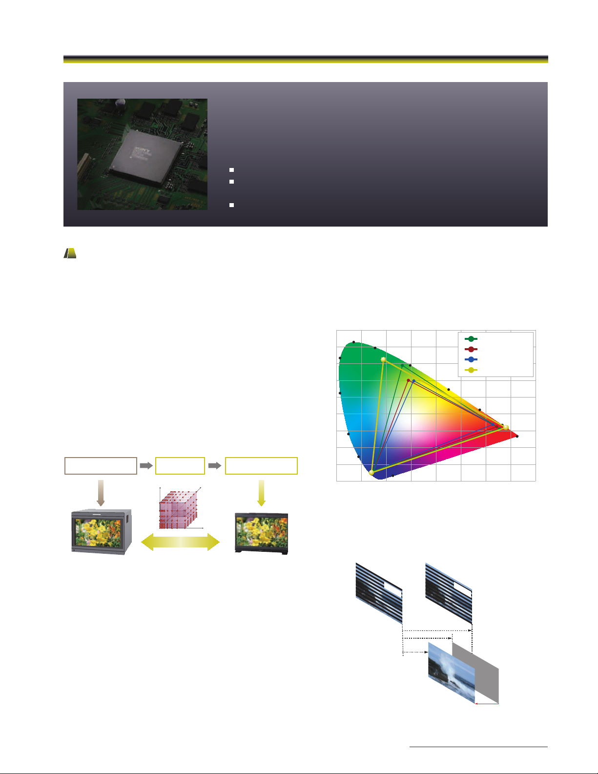
BVM Series
Professional Display Engine
(BVM-E / BVM-F Series-dedicated)
Nonlinear Cubic Conversion color management system
Cutting-edge I/P conversion technology with extremely
low process delay
12-bit output accuracy signal processing
Professional Display Engine
The high-precision signal processing engine has been developed to fulfill the master monitor criteria and is optimized to
maximize OLED panel performance. This engine incorporates 12-bit output accuracy at each process, and provides both a
high quality interlaced to progressive conversion algorithm and a highly accurate color management system.
Nonlinear Cubic Conversion color management
The nonlinear cubic conversion color management system
in the BVM-E and BVM-F Series master monitors use a unique
3D LUT (look-up table) to accurately reproduce the color
gamuts of each broadcast standard such as ITU-R BT.709,
EBU, and SMPTE-C phosphor standards. In addition, the
OLED’s wide color gamut enables D-Cine emulation for digital
intermediate work.*
* D-Cine is a color gamut emulating the color gamut described in SMPTE RP
431-2-2007. The chromaticity of the green-red region is not covered in full;
however, the color shift is subtle in this region.
This feature is supported by the BVM-E Series only.
(CRT RGB)
(R100, G100, B100)
B
3D LUT
G
(OLED RGB)
(R90, G110, B100)
0.900
0.800
0.700
0.600
0.500
0.400
0.300
0.200
0.100
0.000
520
530
510
500
490
480
470
0.100 0.200 0.300 0.400 0.500 0.600 0.700 0.800
550
570
380~410
D-Cine
EBU
SMPTE-C
E250 NATIVE
590
610
700~
780
R
Same color!
Nonlinear Cubic Conversion color management system
Cutting-edge interlaced to progressive conversion
with low process delay
The Sony original interlaced to progressive conversion
technology used in the BVM Series minimizes processing
artifacts found in typical up-conversion processes. This has
been improved in the BVM-E and BVM-F Series so that an
interlaced image is displayed accurately and faithfully.
12-bit output accuracy signal processing
The BVM-E and BVM-F Series use a 12-bit per color display
engine, which allows images to be reproduced with high
precision for display accuracy.
BVM-E Series color gamut
Field 1
BVM-L 11.9 ms
BVM-E / BVM-F 6.2 ms
Sophisticated I/P conversion
Field 2
Original source
1/60=16.6 ms
Picture delay reduced to half
11
Page 12
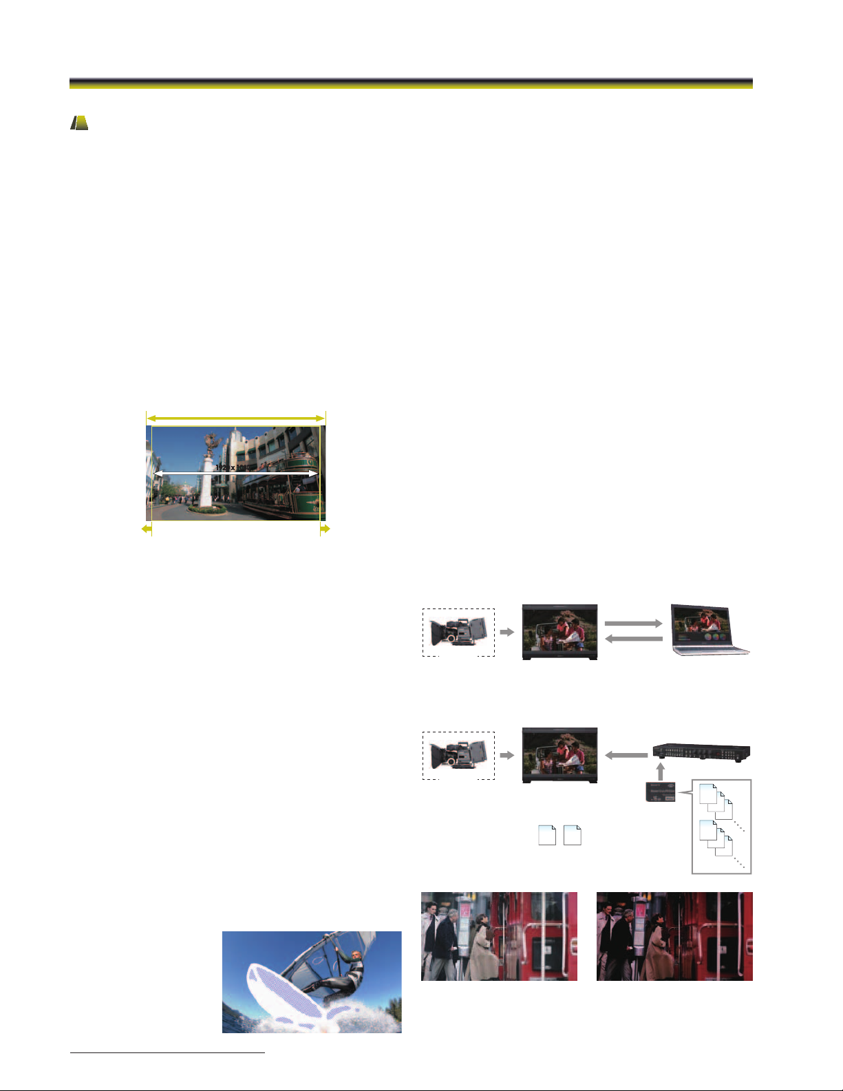
BVM Series
BVM-E Series Digital Cinema Features
The BVM-E Series – comprising BVM-E250 and BVM-E170 master monitors – offers digital cinema features which are
indispensable and ideal for high-quality creative digital cinema onset and post-production workflow.
2K (2048 x 1080, RGB/XYZ) Input
BVM-E250 and BVM-E170 master monitors are capable of
2K (2048 x 1080 resolution, RGB/XYZ) input. The 2K signal
is displayed in two ways as a full 2K image scaled into a
full-HD (1920 x 1080) screen, or as a 2K native display with an
image-slide function.
2048 Image-slide
The 2048 Image-slide function allows 2K resolution (2048 x 1080
pixels) images to be mapped, pixel-to-pixel, on the full-HD
(1920 x 1080 pixels) panel without picture degradation. When
the user needs to view the left or right edge of the picture
frame, they can scroll the image in a horizontal direction.
2048 x 1080
1920 x 1080
1920 x 1080
The image can be horizontally scrolled
S-LOG Gamma
S-LOG gamma is a technique used in Sony’s digital
cinematography cameras that allows the full latitude of the
camera CCD to be maintained throughout the production
chain. Unlike conventional systems, in which highlight
contrast is compressed, S-LOG Gamma logarithmically
converts the video signal using characteristics similar to film
negatives.
This keeps the camera CCD dynamic range intact, even in
extreme highlight areas. Two display modes are offered:
1) S-LOG Full
This mode displays the full dynamic range of the video signal
captured from Sony’s digital cinematography cameras.
2) S-LOG Standard
This mode displays image exposure levels at the lower part
of the S-LOG gamma signal dynamic range, allowing image
areas of regular brightness to be viewed clearly. Higher
exposure levels are clipped in this mode.
Gamut Error Display
This function detects irregular signal input. When an irregular
signal is detected, these master monitors indicate this with a
zebra pattern over the relevant area of the picture.
Gamut Error Display is a
convenient feature that
instantly alerts viewers
to such signals without
requiring the use of a
waveform monitor.
ASC CDL and User LUT Functions
BVM-E Series monitors support the ASC CDL (American
Society of Cinematographers Color Decision List) and User
LUT (Look-up Table) to emulate color grading.
Live images from camera onset can be altered after
importing an ASC CDL format, and/or previewed using a film
print emulation applied to the monitor using Look Creation
Workflow.*
Furthermore, once ASC CDL and User LUT data are created,
information*2 can be saved to Memory Stick® media*3 and
loaded onto the monitor from the BKM-16R controller. Up to
five items of ASC CDL and User LUT data can be imported to
BVM-E Series monitors, so users can easily compare different
color grading (see Look Application Workflow).
These features help with creative decision making and
improve workflow between onset and post-production.
*1 Requires BVM-E firmware V1.1 or later, and third-party software supporting
the BVM-E ASC CDL and User LUT functions (third party software sold
separately).
*2 Up to 1,000 data items.
*3 Can use a Memory Stick, Memory Stick PRO™, Memory Stick Duo™,
Memory Stick PRO Duo
Micro™.
Look Creation Workow
Look Applying Workow
Camera
Camera
1
®
, or (with optional adaptor) Memory Stick
1. Capture
3. Apply
BVM-E250/E170
ASC CDL/User LUT
Image
BVM-E250/E170
ASC CDL/User LUT
Image
ASC
User
CDL
LUT
Preset les
(up to 5 each)
Apply
Memory
Stick
2. Look creation
BKM-16R
ASC
CDL
ASC
CDL
ASC
CDL
User
LUT
User
LUT
User
LUT
Onset graded imageLive image from a camera
Simulated images
12
Page 13
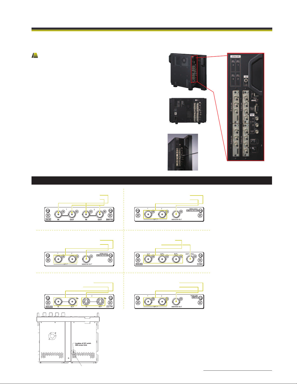
BVM-E Series
• 3G/HD/SD-SDI signal input (x2)
• 3G/HD/SD-SDI monitor output (x2)
BKM-250TG, 3G/HD/SD-SDI Input Adaptor*
* 3G-SDI, HD-SDI and SD-SDI signals are detected automatically
• HD-SDI/SD-SDI signal input (x2)
• HD-SDI/SD-SDI monitor output (x1)
BKM-243HS, HD-SDI/SD-SDI Input Adaptor*
* HD-SDI and SD-SDI signals are detected automatically
• Composite input/output (x1)
• Y/C input/output (x1)
BKM-227W, NTSC/PAL Input Adaptor
• HD-SDI/SD-SDI signal input (x2)
• HD-SDI/SD-SDI monitor output (x1)
BKM-244CC, HD/SD-SDI Closed Caption Adaptor*
* HD-SDI and SD-SDI signals are detected automatically
* Closed-caption decoders (EIA 608 and EIA 708) are equipped
• RGB,Y/PB/PR input (x1)
• EXT SYNC (x1)
BKM-229X, Analog Component Adaptor
• SD-SDI signal input (x2)
• SD-SDI monitor output (x1)
BKM-220D, SD-SDI 4:2:2 Input Adaptor
Signal-interface Options
BVM-E250 Input ports
BVM-E170 Input ports
Standard 3G-SDI interface
Input Versatility
Multi-format signal support
BVM-E250 and BVM-E170 monitors support various input
signals ranging from 720 x 76/0i to 1920 x 1080/0P, 60P,
digital cinema (D-Cine) 2048 x 1080/24P, and numerous
computer signals up to 1920 x 1080.
Standard 3G-SDI inputs plus versatile optional ports
These monitors are equipped with two standard 3G/HD/
SD-SDI inputs and an HDMI (HDCP correspondence) input. In
addition, four option ports are available. This increases system
versatility and allows users to add decoders for signal formats
not supported by the supplied inputs, including extra 3G-SDI,
HD-SDI, or SD-SDI, and Dual-link HD-SDI, RGB, Y/CB/CR, Y/C, and
composite signal inputs.
DisplayPort*
These monitors are also equipped with a standard DisplayPort
for future expansion.
*Expected availability December 2011.
BVM Series
BVM Advanced Features
Input Versatility
Multi-format signal support
BVM-E and BVM-F Series monitors support various input
signals ranging from 720 x 76/0i to 1920 x 1080/0P, 60P,
digital cinema (D-Cine) 2048 x 1080/24P*, and numerous
computer signals up to 1920 x 1080.
* 2048 x 1080/p signals are supported by the BVM-E Series only.
Standard 3G-SDI inputs plus versatile optional ports
These monitors are equipped with two standard 3G/HD/
SD-SDI inputs and an HDMI (HDCP compliant) input.
In addition, four option ports are available. This increases
system versatility and allows users to add decoders for signal
formats not supported by the supplied inputs, including extra
3G-SDI, HD-SDI, or SD-SDI, and Dual-link HD-SDI, RGB, Y/CB/CR,
Y/C, and composite signal inputs.
DisplayPort*
These monitors are also equipped with a standard DisplayPort
for future expansion.
* This will be supported by monitor firmware in V1.1 or later.
Signal-interface Options
BKM-250TG, 3G/HD/SD-SDI Input Adaptor*
• 3G/HD/SD-SDI signal input (x2)
• 3G/HD/SD-SDI monitor output (x2)
BVM-E250 Input ports
BKM-244CC, HD/SD-SDI Closed Caption Adaptor*
• HD-SDI/SD-SDI signal input (x2)
• HD-SDI/SD-SDI monitor output (x1)
BVM-E170 Input ports
Standard 3G-SDI interface
* 3G-SDI, HD-SDI and SD-SDI signals are detected automatically
BKM-243HS, HD-SDI/SD-SDI Input Adaptor*
• HD-SDI/SD-SDI signal input (x2)
• HD-SDI/SD-SDI monitor output (x1)
* HD-SDI and SD-SDI signals are detected automatically
BKM-227W, NTSC/PAL Input Adaptor
• Composite input/output (x1)
• Y/C input/output (x1)
* HD-SDI and SD-SDI signals are detected automatically
VMM-4SNY, Integrated Test and Measurement Module
• Two HDSDI/SDI inputs
• Waveform monitor, Vectorscope, Gamut Error, and Audio display
VMM-4SNY-3GB, Integrated Test and Measurement Module
• Two 3G/HDSDI/SDI inputs
• Waveform monitor, Vectorscope, Gamut Error, and Audio display
* Closed-caption decoders (EIA 608 and EIA 708) are equipped
BKM-229X, Analog Component Adaptor
• RGB,Y/PB/PR input (x1)
• EXT SYNC (x1)
BKM-220D, SD-SDI 4:2:2 Input Adaptor
• SD-SDI signal input (x2)
• SD-SDI monitor output (x1)
13
Page 14
BVM Series
Signal Analyzing Functions
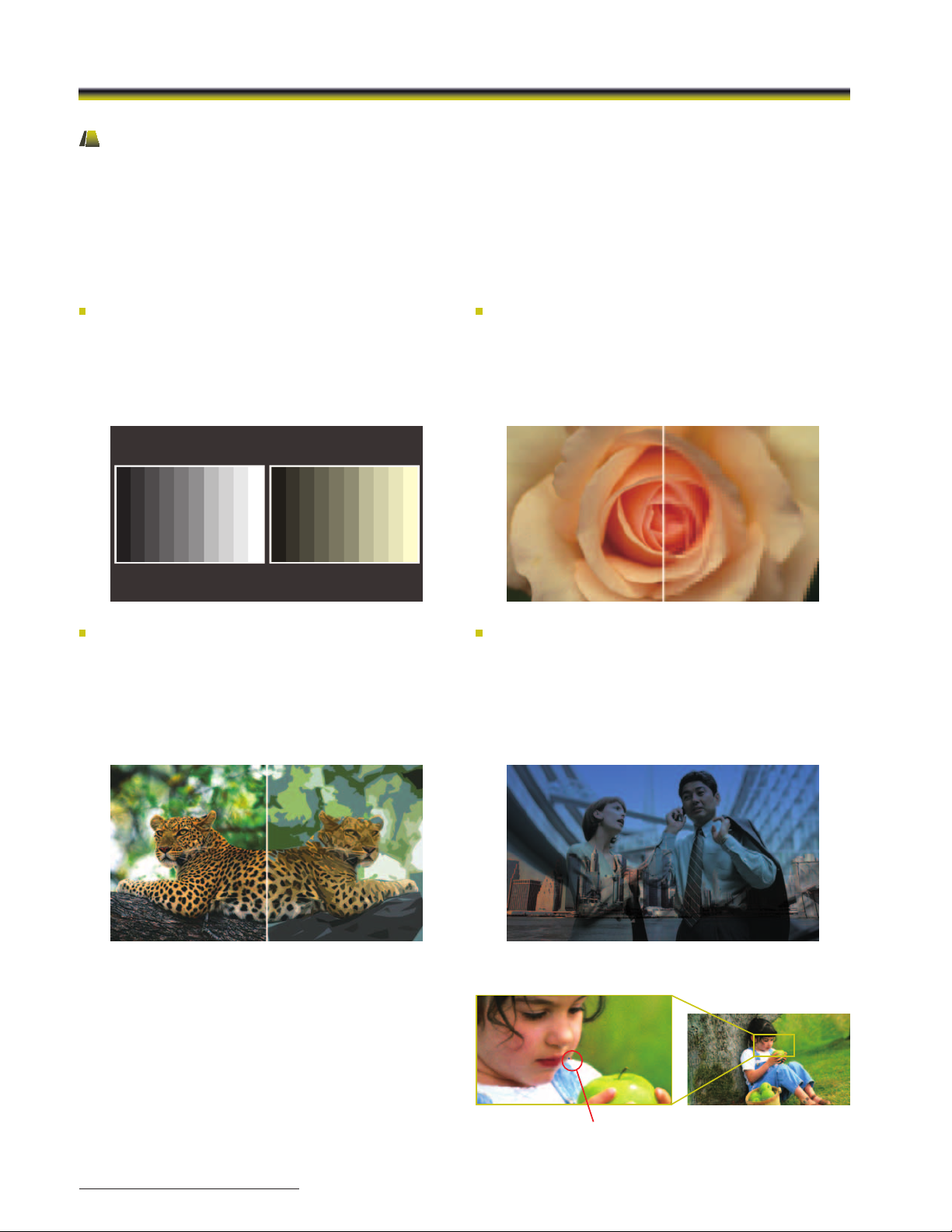
Picture & Picture
The unique Picture & Picture function of the BVM-E and BVM-F Series allows simultaneous display of two input signals on the
monitor’s screen. This function is extremely convenient for making instant adjustments to two input sources, because there is no
need to individually adjust the different characteristics of two monitors.
This function comes in handy for adjustments between two cameras, special-effects creation, time-lapse shooting, and
computer graphics (CG) work. The BVM-E Series offers four Picture & Picture modes and the BVM-F Series offers a side-by-side
mode:
Side-by-side
The two picture images are downscaled using a
digital filter and displayed side-by-side. This feature is
convenient when making white balance adjustments or
determining shooting angles between two cameras.
Butterfly (BVM-E Series only)
The two inputs are displayed as line-symmetric images on the
left and right halves of the screen. By adjusting the H-position
controller, the two images can be moved inward to the
middle of the screen. An instant comparison of the moving
images can then be made easily and accurately, without the
user having to move their eyes.
WIPE (BVM-E Series only)
The area of the two pictures to be displayed is selected using
a vertical WIPE pattern, which is controlled from the BKM-16R.
This function is useful when picture detail of the two images
must be examined on a pixel basis. This is normally used to
review still images.
Blending (BVM-E Series only)
The two picture images are overlapped for display, and the
mix ratio is adjustable. This function is useful to verify whether
a foreground signal is accurately keyed into the background
signal, or when combining shoots with live action and
computer-generated effects.
Pixel Zoom
Pixel Zoom is a function for magnifying images. A selected
area of the displayed picture can be enlarged on a pixel
basis, up to eight times in size both vertically and horizontally.
Because this function does not use scaling, the desired
picture content is magnified and displayed faithfully to the
raw input signal. This function is useful when evaluating
precise picture edges, such as for chroma keying.
* This function is effective when the input signal is displayed in “Native Scan”
mode.
14
Error Signal
Simulated images
Page 15
BVM Series
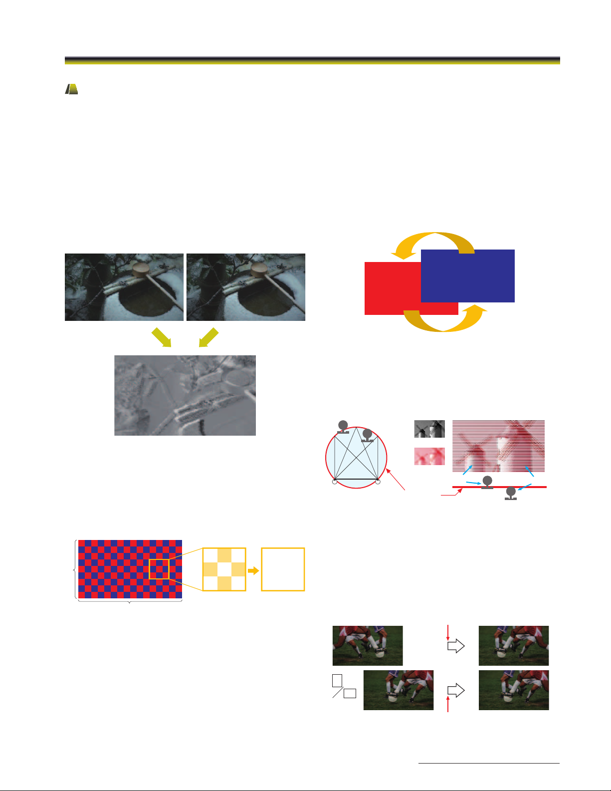
3D Signal Analyzing Functions
By installing the optional BKM-20TG 3G/HD-SDI input adaptor*, the BVM-E and BVM-F Series monitors can support a variety of
3D signal analyses. The 3D signals are displayed in 2D mode.
* Difference display” function require the BKM-20TG serial No. 7300001 or higher, and other functions require the BKM-20TG serial No. 7100001 or higher.
Difference Display
This function displays the difference between the luminance
signal of the left (L) and right (R) images of the 3D signal.
When the luminance levels of the two signals are the same,
the signals are displayed in gray. When they are different, a
monochrome image is displayed according to the variation
in luminance. This function is useful for checking the amount
of parallax.
L/R Switch
Left and right signals can be swapped in a moment without
inserting black frames, simply by manually pushing a function
key. This instant-swap capability enables users to compare
the entire images and check for any sense of incongruity or
for unnatural images.
LinkB
LinkA
R
L
Horopter Check
This function helps users to perceive the subtle difference of
depth between different objects placed on the 3D screen
surface.
Simulated display image
L (Mono)
Checker Board
Left and right input signals are displayed in a grid pattern on
screen. By comparing adjacent images, users can recognize
a difference in brightness and the color setting of the left
and right images, and thus easily adjust the camera’s white
balance and iris settings.
L R L R L R L R L R L R L R L R
L R L R L R L R L R L R L R L R
L R L R L R L R L R L R L R L R
9
L R L R L R L R L R L R L R L R
L R L R L R L R L R L R L R L R
LR L R L R L R L R L R L R L R
L R L
LR L R L R L R L R L R L R L R
R L R
LR L R L R L R L R L R L R L R
L R L
LR L R L R L R L R L R L R L R
L R L
R L R
L R L
16
Simulated images
L-eye R-eye
R (Red)
Horopter
Rear
Front
Image overview when viewed from above
Horizontal Flip
When a half-mirror type of rig is used, either the left or right
signal may be reversed horizontally. The Horizontal flip
function turns the reversed image to the normal view.
* A delay in signal processing occurs, and both the left and right signals
synchronize to the delayed signal.
Delayed by Flip H process
R
L
Delayed for synchronization
15
Page 16
BVM Series
Convenient Features
Interlace Display
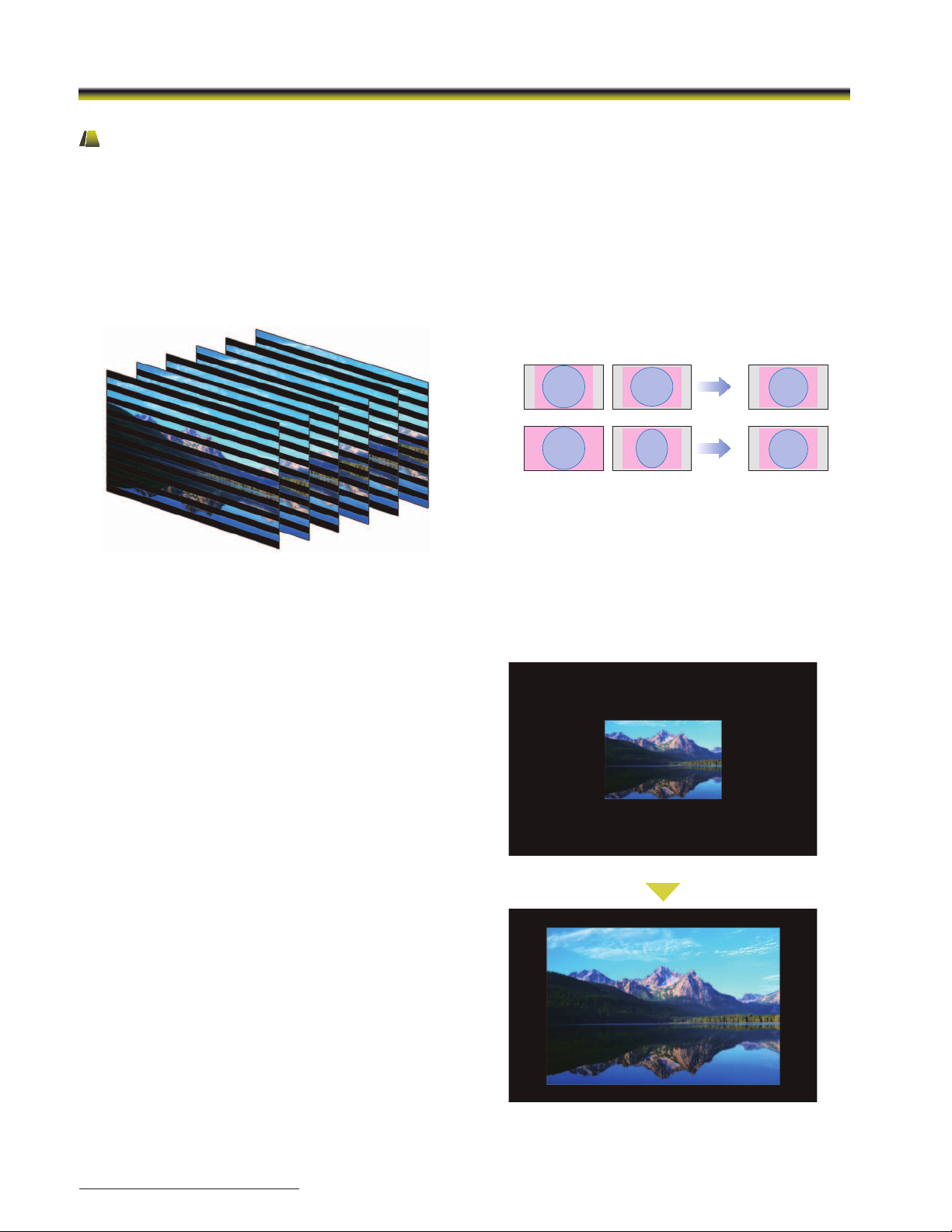
BVM-E and BVM-F Series monitors offer an Interlace Display
feature for 1080i and SD inputs. This lets each BVM-E and
BVM-F monitor display these inputs as a true interlace
display. As with the Native Scan function, Interlace Display
mode offers faithful reproduction of the input signal, and
the displayed interlace fields are free from the picture
degradation that can occur as a result of typical I/P
conversion processes.
Aspect Correction Mode
PAL and NTSC video systems are all based on rectangular
pixels. Display of these formats on a square pixel panel
typically distorts the image. The BVM-E and BVM-F Series use
a unique process called Aspect Correction which, while still
offering native pixel performance, continues to display image
geometry correctly. This scaling technique used in BVM-E
and BVM-F Series monitors corrects horizontal distortion while
keeping the vertical pixel count correctly displayed.
Normal Scan Native Scan (x2) Aspect Correction
Scan Switch
The Scan Switch function allows switching between under
scan (-3%), normal scan (0%), and over scan (mask of the 5%
over scan portion in the normal scan).
Native Scan (pixel-to-pixel display)
Conventional flat-panel monitors reproduce images using
scaling and I/P conversion due to their fixed pixel counts and
progressive scanning processes. The Native Scan function
is a unique display mode that reproduces images without
changing the input signal’s pixel count.
For example, when an SD signal is input, the BVM-E and BVM-F
Series monitors will reproduce the image at a picture size of
720 x 487* pixels. For SD inputs the Native Scan function also
allows the displayed image size to be doubled to 1440 x 974*
by duplicating and doubling each pixel both horizontally and
vertically.
* The 2/9.94i signal specified by Rec. ITU-R BT.601.
SD 4:3
SD 16:9
(Squeeze)
Example of NTSC signal on the 16:9 aspect panel – BVM-E250
720 x 487 Native Scan
487 x 2
487 x 2
HD Frame Capture
The HD Frame Capture function of the BVM-E and BVM-F
Series allow a picture frame from the 3G-SDI and HD-SDI input
to be captured and saved as a picture file on MemoryStick
media.* This picture file can be used as a reference for
various purposes; for example, as for picture-tone adjustments
between past images and for camera-framing adjustments.
* Memory Stick PRO (High-Speed) / Memory Stick PRO Duo (High-Speed)
can be used.
16
1440 x 974 Native Scan (720 x 487) x 2
Simulated images
Page 17
BVM Series
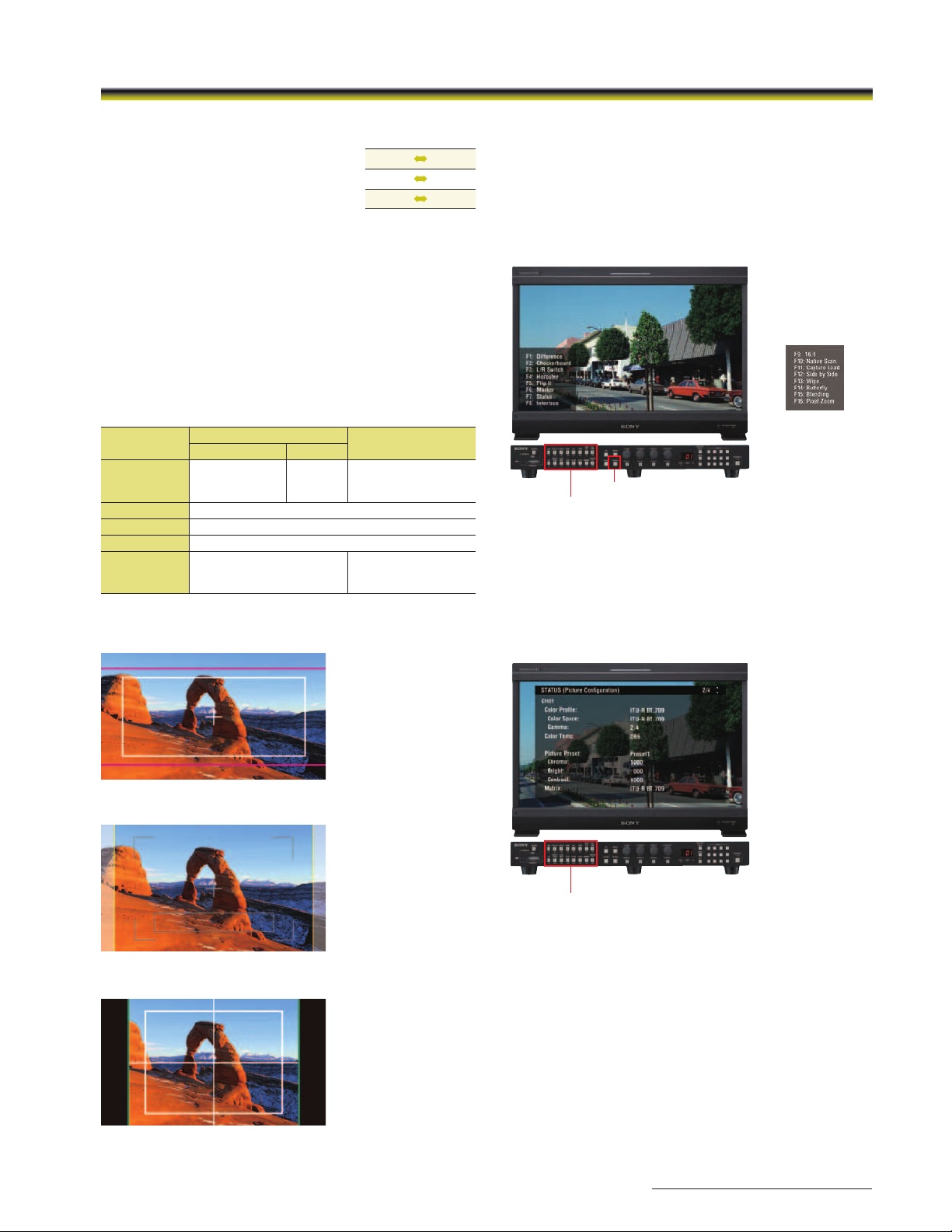
Aspect switch
The aspect ratio can be switched
between 4:3, 16:9, 2.39: 1, and 1.896:1
depending on the input signal.
* The BVM-F Series monitors support 16:9 and 4:3
only.
16:9 4:3
16:9
1.896:1
2.39:1
2.39:1
Marker settings
BVM-E and BVM-F Series monitors can display various markers,
including an aspect marker, safe area marker, and center
marker. In addition to this flexible selection of marker types,
detailed display settings of each marker are offered. For
example, the color, brightness, horizontal/vertical position,
and width of aspect markers can all be controlled, while the
height and width of safe area markers can be adjusted.
Marker Variation
Safe Area Marker
% Dot (Pixel)
Selectable
Markers
Line Colors
Line Width
Line Luminance
Blanking
* The BVM-F Series monitors support Aspect Markers of 16:9 and 4:3 only.
80%, 88%, 90%, 93%,
or variable
White, Red, Green, Blue, Yellow, Cyan, or Magenta
Flexible
1 to 5 dots (factory preset at 2 dots)
High (bright) or Low (dark)
—
Marker Examples
Aspect Marker*
16:9, 15:9, 14:9, 13:9, 4:3,
2.39:1, 2.35:1, 1.896:1,
1.85:1, or 1.66:1
Off: Blanking is released
Black: Blanking
Half: Half blanking
Wide Variety of Functions
The user has a wide variety of over 40 functions to choose
from.
Each of these can be assigned to any of the 16 function
buttons (F1 to F16) on the BKM-16R controller.
Press ENTER to display the F1 to F8 (or F9 to F16) button
assignment on screen.
(The next Function
display)
ENTER button
F1 to F16 function buttons
Screen image is simulated
Status Display
Simply assign STATUS to one of the function buttons (F1 to F16)
on the BKM-16R controller.
The user can instantly grasp the whole monitor status and
configurations without having to search through menus.
Aspect Mode: 2.3:1,
Safe Area: Shape A,
Area Size: 80
Aspect Mode: 14:9,
Safe Area: Shape B,
Area Size: 80
Aspect Mode: 4:3,
Safe Area: Shape C,
Area Size: 80
F1 to F16 function buttons
Screen image is simulated
17
Page 18
BVM Series
Modular Monitor Control Unit (BKM-16R)
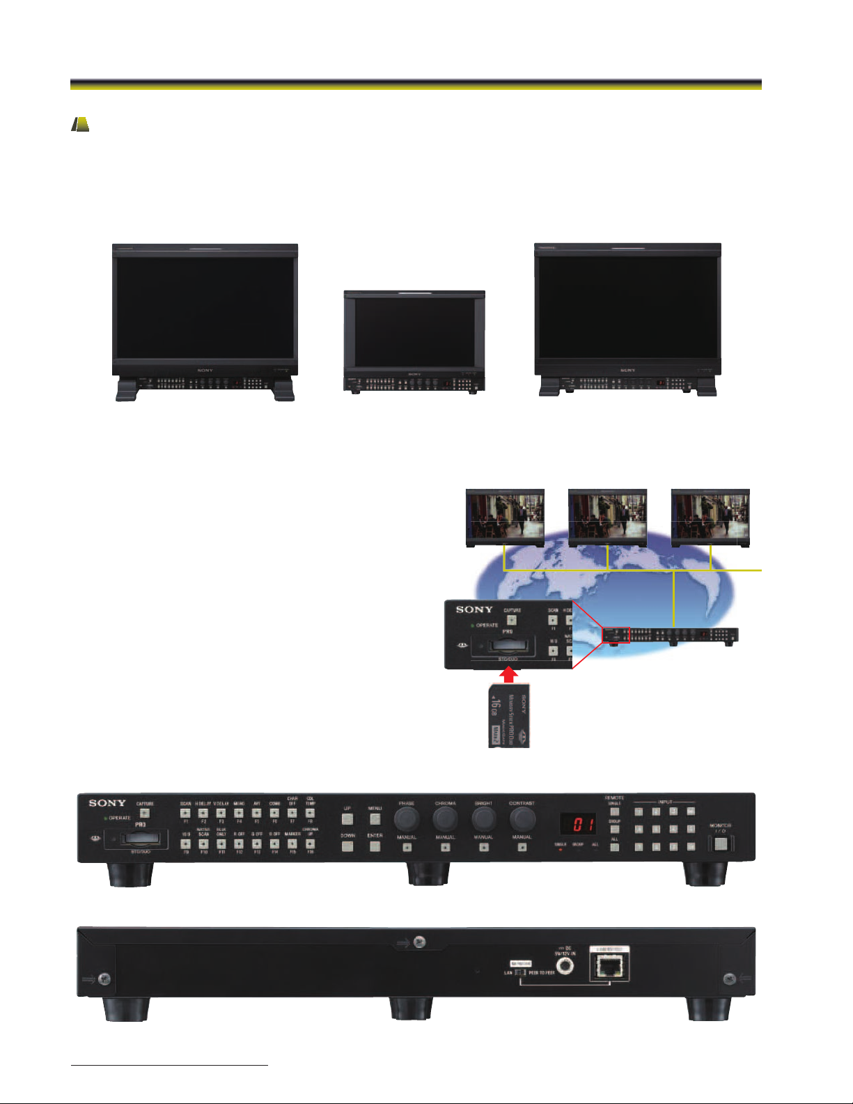
BVM-E and BVM-F Series monitors and their control panels are provided as separate units, allowing greater flexibility for system
integration. The BVM-E and BVM-F Series monitors incorporate a monitor control unit, the BKM-16R as an option.
This BKM-16R control unit can be attached beneath the monitor using the optional controller attachment stand*, or connected
remotely via an Ethernet cable.
* The BVM-E20 and BVM-F20 use the BKM-37H and BKM-38H Attachment Stands. The BVM-E170 and BVM-F170 use the BKM-39H Attachment Stand.
BVM-E250 monitor
BKM-16R monitor control unit
BKM-37H attachment stand
BVM-E170 monitor
BKM-16R monitor control unit
BKM-39H attachment stand
Copy function for monitor setup and adjustment data
The optional BKM-16R control unit includes a Memory Stick slot*1
to save and load monitor configuration and adjustment settings.
This is useful for multiple monitor systems, allowing the transfer of
one monitor’s setup and adjustment data to another.*
2
This data can also be transferred via the BVM’s Ethernet
connection.
*1 Memory Stick, Memory Stick PRO, Memory Stick Duo, Memory Stick PRO Duo,
and Memory Stick Micro (an optional adaptor is required) can be used.
*2 Data can be moved between BVM-E and BVM-F Series monitors.
“+12dB Chroma UP” function
A Chroma UP” button located on the front panel of the BKM-16R
allows the chroma level to be boosted by +12 dB.
This is a convenient feature for adjusting camera white balance
with a higher degree of accuracy.
BKM-16R Monitor Control Unit
BVM-F250 monitor
BKM-16R monitor control unit
BKM-38H attachment stand
Ethernet
Front panel
Rear panel
18
Page 19
BVM Series
Ethernet-based remote control
The BVM-E and BVM-F Series monitors and the BKM-16R
Monitor Control Unit are equipped with an Ethernet port,
allowing remote control of display parameters across a
standard Ethernet connection. One BKM-16R Monitor Control
Unit can control up to thirty-two (32) BVM* monitors.
* Includes BVM-A CRT monitors, BVM-L , PVM-L, and BVM-E/-F Series monitors.
Easy Setup and Adjustment
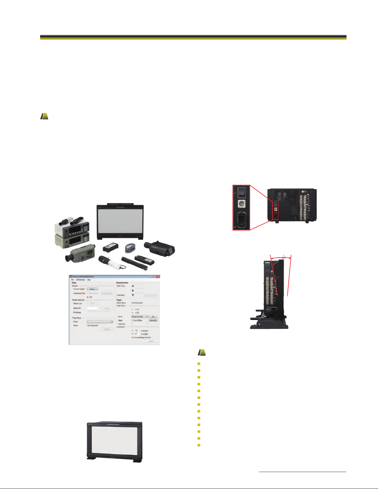
Auto White Adjustment*
The BVM-E and BVM-F Series monitors employ a software-based
color temperature (white balance) calibration function, which
is called “Monitor_AutoWhiteAdjustment”. Combined with a PC
and commercially available calibration tools*2, this function
enables simple adjustment of the monitor’s white balance.
*1 Supported with version 1.1 or later BVM monitor operation system
software.
*2 Konica Minolta CA-210, CA-310, CS-200, DK-Technologies PM639/06,
X-Rite i1 (Eye-One) Pro, Photo Research PR-670, Klein K-10, and ETI
specbos 1211. A connector is required for each color analyzer.
Calibration tools and connectors are sold separately.
1
“Character Off” button
To facilitate parameter adjustments, the On-Screen Menu
indication can be taken off the screen, while in Menu mode.
The On-Screen Menu indication can be toggled on or off with
a simple press of a button on the BKM-16Rs front panel.
Auto Chroma / Phase adjustment*
An Auto Chroma / Phase / Matrix setup function is provided
on BVM-E and BVM-F Series monitors, which automatically
adjusts the monitor’s chroma, phase, and matrix using
external color bars.
* Supports analog signal inputs only.
DC operation
The BVM-E170 and BVM-F170 can be DC operated. Due to
their lightweight and small-size design, with a comparable
height to the former 14-inch BVM-CRT monitors, the BVM-E170
and BVM-F170 are ideal for field and OB van applications.
BVM-E170 rear view
“Monitor_AutoWhiteAdjuestment” GUI image
Built-in Color Sensor for Auto White Adjustment
The BVM-E170 and BVM-F170 are equipped with a built-in
color sensor, which allows the user to calibrate the monitor’s
color temperature (white balance) as needed without an
external probe. Calibration performance is minimally affected
by ambient light.
This function ensures color and gamma consistency, and
reduces user maintenance tasks.
Tilt stand for BVM-E250 / F250
10° 5°
BVM-E250 with the optional BKM-37H tilt stand
Other features
VESA™ Mounting (200 x 100 mm pitch)*
EIA 19-inch Standard Rack-mountable*
Blue Only
Mono
H Delay / V Delay
NTSC Setup Level (0%, 7.5%)
Component Level (SMPTE / EBU-N10 or Betacam)
Aperture
Serial Remote (Ethernet)
Parallel Remote (D-sub 9-pin)
Tally Lamp (Amber)
EXT Sync (for RGB / YUV)
Remote Maintenance
*1 BVM-E20 / BVM-F20 only.
*2 BVM-E170 / BVM-F170 only. Mounting brackets are supplied.
1
2
19
Page 20
TRIMASTER EL OLED Picture Monitor
For Critical Picture Viewing
PVM-2541 PVM-1741 PVM-740
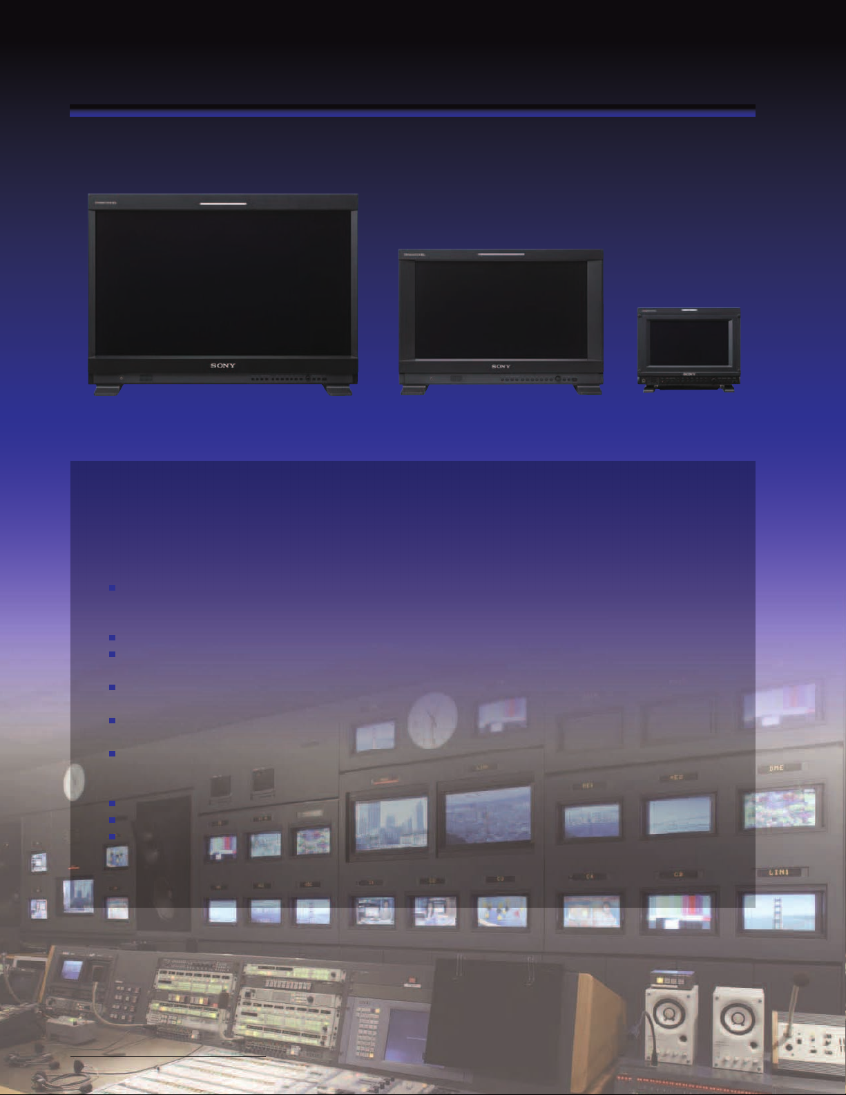
The PVM-2541 and PVM-1741 as well as the PVM-740 are all-in-one
TRIMASTER EL OLED picture monitors, delivering unparalleled picture
quality with the performance features and functions found in more
expensive monitors, all contained in a compact, robust, one piece design.
Sony Super Top Emission OLED display panel with 10-bit RGB:
• 24.-inch*
• 7.4-inch*
Wide dynamic range display
New compact metal chassis
• Lightweight and robust metal body
Standard inputs
• 3G/HD/SD-SDI input (x2)*
Built-in tools
• Waveform monitor, audio level meter, timecode*
Easy-to-use control panel
• Rotary-type switch for quick menu access
• Seven function-assignable buttons for direct and quick access
DC 12V operations (PVM-1741 and PVM-740)
Auto white adjustment with PC application software
External remote control function (parallel and serial remote)
*1 623.4 mm, 419.7 mm, and 188.0 mm (respectively), measured diagonally.
*2 The PVM-740 is equipped with one SDI input connector.
*3 The PVM-740 does not support timecode display.
1
and 16.5-inch*1 (Full HD 1920 x 1080 pixels)
1
(uarter HD 960 x 40 pixels)
2
, HDMI (HDCP) (x1), and Composite (x1)
3
20
Page 21
PVM Series
Groundbreaking Picture Performance with Sony OLED Technologies
The Sony 24.5-inch*3, 16.5-inch*3, and 7.4-inch*3 Super Top Emission OLED display panels provide unparalleled
black performance, a wide color gamut, and quick pixel response with virtually no motion blur.
1
By combining the Sony OLED display panel (Full HD*
, 10-bit driver) and the Sony OLED processing technologies*2,
the PVM Series of OLED monitors deliver exceptional picture quality never before seen in conventional picture
monitors.
*1 The PVM-740 delivers uarter HD (960 x 40) resolution.
*2 The PVM-740 is equipped with the ChromaTRU processing technology.
*3 Viewable area measured diagonally.
Main Features
Sony OLED with Full HD*
and 10-bit RGB
The PVM-241 and PVM-1741 OLED panel with Full HD
resolution (1920 x 1080) and a 10-bit RGB driver, together
with the Sony Super Top Emission OLED display panel, creates
lifelike and smoother-than-ever gradation from dark to bright
portions of a scene such as in a sunrise or sunset.
* The PVM-740 delivers uarter HD (960 x 40) resolution.
Sony OLED
Full HD, 10-bit
8-bit (256-levels) image 10-bit (1024-levels) image
Simulated images
Superb Black Performance
Thanks to the Sony OLED system, deep blacks can be
accurately displayed and the black portion of an image is not
degraded.
Wide Color Gamut and High-purity
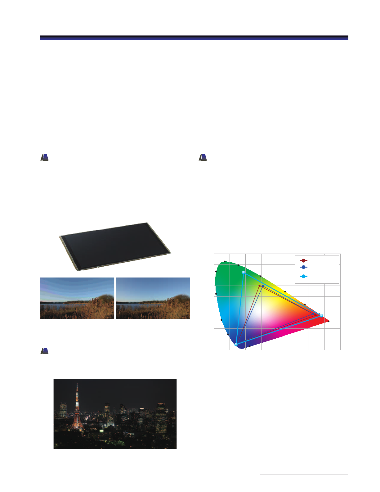
Deep Color Reproduction
The Sony OLED technology shows the largest color range
of any Sony monitor ever offered. Color standards such as
ITU-R BT.709, EBU, and SMPTE-C are displayed more accurately
and, if desired, the OLED panel’s native color gamut can be
displayed. The Sony micro-cavity structure uses an optical
resonance effect in combination with accurate color filters to
calibrate and stabilize RGB color accuracy. This combination
is also effective in reducing ambient light reflection, and
consequently deep color reproduction can be achieved
without degradation, particularly in bright environments.
0.900
0.800
0.700
0.600
0.500
0.400
0.300
0.200
0.100
0.000
520
530
510
500
490
480
470
0.100 0.200 0.300 0.400 0.500 0.600 0.700 0.800
PVM Series OLED monitors color gamut
550
570
380~410
EBU
SMPTE-C
PVM OLED
NATIVE
590
610
700~
780
Black performance image
Simulated image
2121
Page 22
PVM Series
Quick Response with virtually
Blur-free Motion
Because the OLED electroluminescent layer inherently
responds to any electrical current input, it emits light
immediately. By this mechanism, excellent quick response
characteristics can be achieved on fast-motion images.
This efficient virtually blur-free, fast response benefits a variety
of applications and scenes, e.g., in sports broadcasting,
monitoring of camera panning, and text scrolling.
Simulated image
Superb Uniformity
The PVM-2541 and PVM-1741 monitors incorporate a newly
developed OLED process to bring out the full performances of
the Sony OLED panels.
This OLED processor offers superb uniformity across all signal
levels at every point of the screen. At the factory, the OLED
panel uniformity is precisely measured and corrected using a
sophisticated RGB LUT (look-up table) adjustment system.
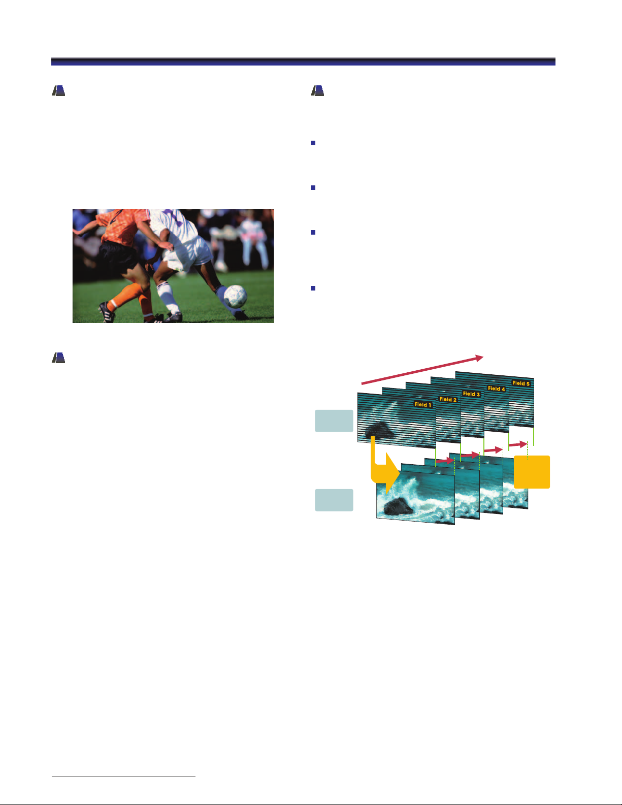
I/P Mode Selection
The PVM-241 and PVM-1741 monitors provide four I/P modes
so that users can select the most suitable mode for each
purpose:
INTER-FIELD:
This mode interpolates images between fields. This is used
for picture quality precedence (e.g., to reduce the jagged
effect on moving pictures).
INTRA-FIELD:
This mode interpolates images within the field, and delivers
naturally reproduced images and quick picture processing.
This mode is available only for 1920 x 1080 SDI signal input.
FIELD MERGE:
This mode combines lines alternately in odd and even
fields, regardless of picture movements. This is used for PsF
(Progressive Segmented Frame) processing and still image
monitoring.
LINE DOUBLER:
This mode interpolates by repeating each line. This is
used for editing and monitoring fast-moving images, and
checking line flicker. The minimum processing time is less
than one field (0.5 frames).
Signal Flow
Interlaced
signal
I/P conversion by
“LINE DOUBLER” mode
(No need to wait for
the next eld to come)
After I/P
conversion
Signal
Processing
period is less
than 1 eld.
2222
LINE DOUBLER I/P mode image
Page 23
PVM Series
Lightweight Compact Design
– Flexible Mounting For Picture
Monitoring
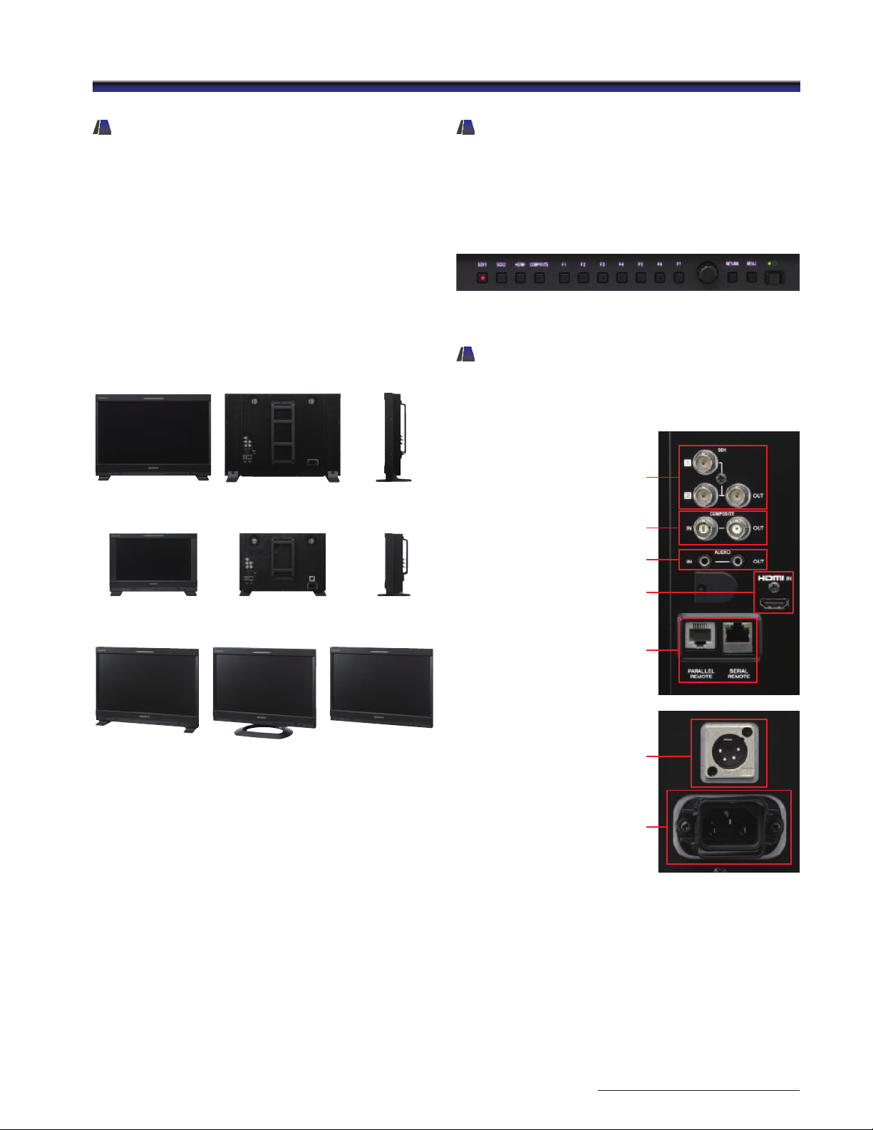
The PVM-2541 and PVM-1741 incorporate a lightweight,
compact metal body. Their design offers flexibility, and can
be adapted according to the application: a desktop unit with
standard table feet, or used with an optional SU-561 stand, or
without the stand for wall applications.
These monitors support VESA mounting with a 100 mm pitch,
and EIA 19-inch standard racks.* This allows the monitors to
be used for all types of application – desktop editing, office
viewing, on a studio monitor wall, or installed in OB vans.
* The PVM-1741 only is available with standard rack-mount brackets.
PVM-2541 front
PVM-2541 rear
PVM-2541 side
Easy-to-use Control Panel
A rotary-type switch and seven function-assignable buttons
allow users quick and intuitive operation. Operation buttons
with LED indicators enable error-free operation, even in dark
environments.*
* LED lights can be switched on/off.
A menu setting is available to dim the lights.
Control panel with LED lights-on
Input Versatility
The PVM-2541 and PVM-1741 monitors are equipped with
built-in standard input interfaces: 3G/HD/SD-SDI (x2), HDMI
(HDCP) input (x1) and composite (x1).
SDI (3G/HD/SD)
input (x2)
output (x1)
Composite input /output
PVM-1741 front
PVM-2541
standard
PVM-1741 rear
PVM-2541
with optional SU-561
PVM-1741 side
PVM-2541
without stand
Audio input / output
HDMI IN
Parallel remote / Serial remote
DC IN
AC IN
2323
Page 24
PVM Series
Waveform Monitor, Audio Level
Meter, and Time Code Display
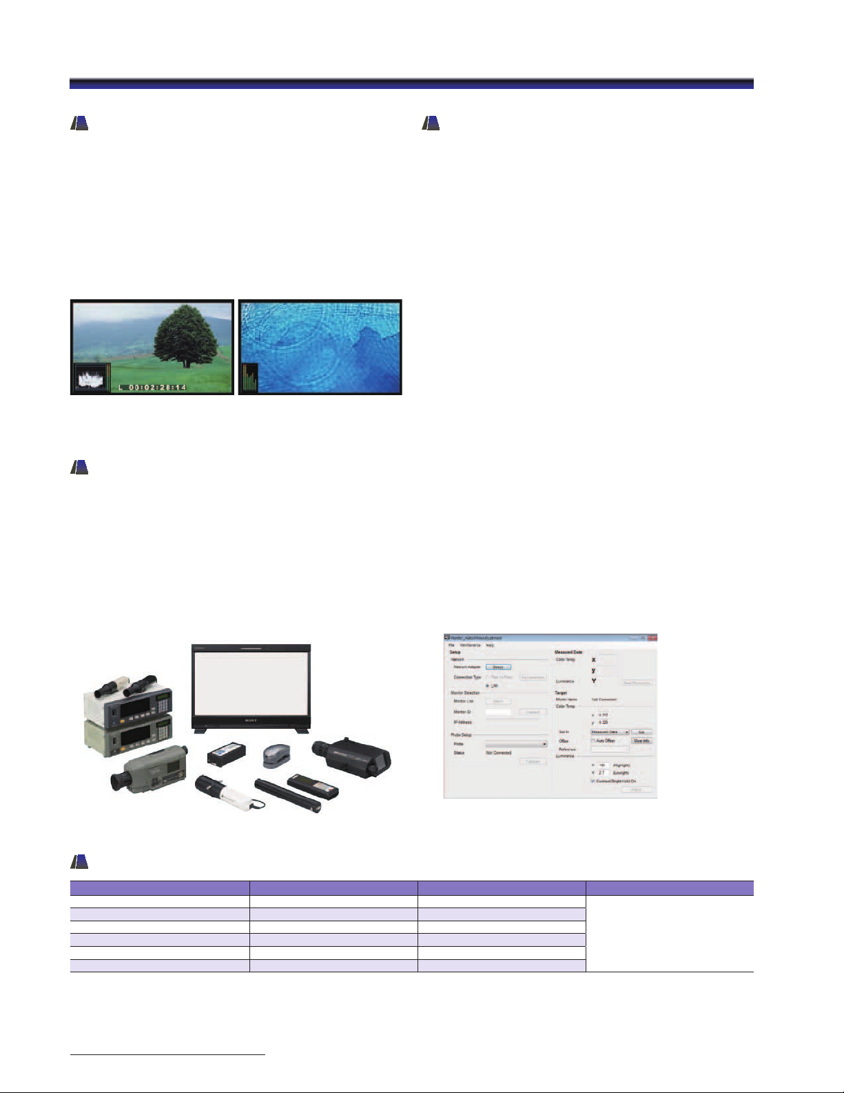
Input signal waveform with a 2-channel audio level meter
can be displayed on screen. When a HDSDI or SDI interface
is connected, the embedded audio level can be displayed
on screen with an 8-channel audio level meter. Time code
embedded on SDI signals can be displayed on screen. Users
can select either LTC or VITC.
* The Audio Level Meter function works only when receiving SDI-embedded
audio signals.
The waveform monitor,
2-channel audio level meter,
and time code display
The 8-channel audio level
meter
Simulated images
Auto White Adjustment
The PVM-2541 and PVM-1741 as well as PVM-740
monitors employ a software-based color temperature
(white balance) calibration function, which is called
“Monitor_AutoWhiteAdjustment”. Combined with a Windows®
PC and commercially available calibration tools*, this function
enables simple adjustment of the monitor’s white balance.
* The Konica Minolta CA-210/CA-310/CS-200, DK-Technologies PM639/06,
X-Rite i1 (Eye-one) Pro, Photo Research PR-670, Klein K-10, and ETI specbos 1211.
External Remote Control Function
The PVM-2541 and PVM-1741 have an external remote control
capability for input/output signal selection and adjustment
of various items via an Ethernet (10BASE-T/100BASE-TX)
connection. Up to 32 monitors and up to four control units
can be connected via Ethernet connection and controlled
remotely on the network. Also these monitors support some
functions of the BKM-16R an optional remote control unit
for BVM-E/BVM-F/BVM-L/PVM-L Series monitors such as the
power on/off switch and the Input Select function.*
* The PVM-241 and PVM-1741 do not support all BKM-16R functions.
“Monitor_AutoWhiteAdjuestment” GUI image
PVM-2541 / PVM-1741 DVI Input Signals
Resolution Dot clock (MHz) fH (kHz) fV (Hz)
640 x 480 25.175 31.5
1280 x 768 68.250 47.4
1280 x 1024 108.000 64.0
1360 x 768 85.500 47.7
1440 x 900 88.750 55.5
1680 x 1050 119.000 64.7
• When a DVI signal is input to the HDMI IN connector using a DVI conversion cable.
• Sides of the displayed picture may be hidden depending on the input signal.
2424
60
Page 25
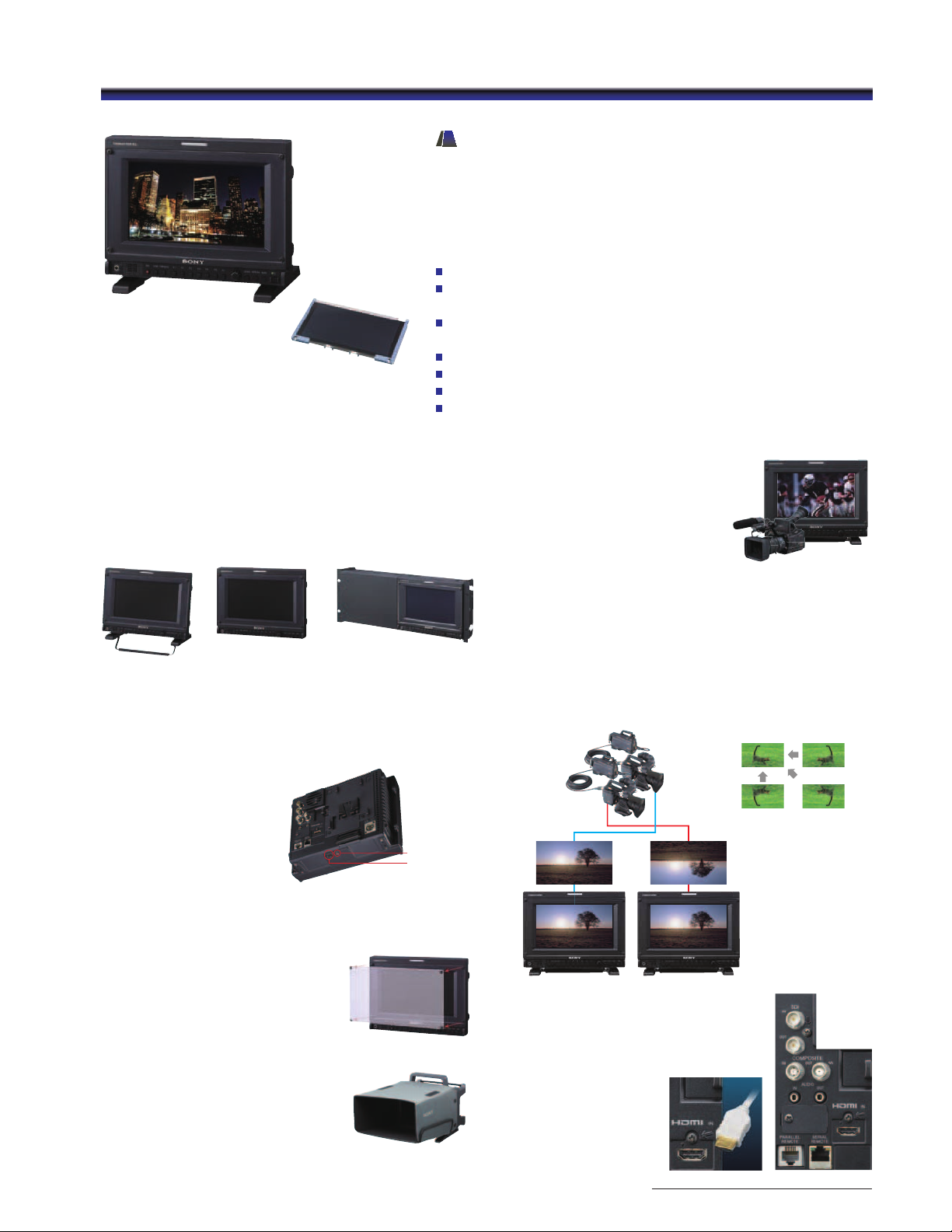
PVM-740
Simulated image
7.4-inch OLED panel
PVM Series
TRIMASTER EL OLED Portable Picture
Monitor – PVM-740
The PVM-740 is a portable monitor in the PVM Series of OLED
monitors. It packs high performance and a variety of features
and functions in its robust and compact body.
Sony Super Top Emission OLED panel with a 10-bit RGB driver
Deep black and high contrast, high-purity deep color reproduction,
and quick response with virtually no motion blur
Wide color gamut and accurate gamma supporting broadcast
standards (SMPTE-C, EBU, and ITU-R BT.709)
Audio level meter and waveform monitor
Screen saver function
Silent mode
External remote function
Robust, light-weight, and compact body
Incorporating a light-weight and compact aluminum-diecast
body with a detachable AR-coated protection panel,
this model is flexible enough to change style according
to user requirements: with or without stand (which is
easily detachable), tilted on a stand (15-degree slant),
rack-mounted, or set on a camera pedestal.
PVM-740
with supplied
stand tilt (15°)
PVM-740
without stand
PVM-740 installed in the
optional MB-531 19”
mounting bracket with
MB-532 mounting panel
Screw holes for camera pedestal
With 3/8-inch and 1/4-inch
screw holes on its base, the
PVM-740 can be installed in
a camera pedestal.
1/4 inch hole
3/8 inch hole
PVM-740 rear and bottom
Camera focus function
The PVM-740 can control and
increase the aperture level of a video
signal, and display images on the
screen with sharpened edges to
help camera focus operation. This
camera focus function can even
be enhanced when combined with
native scan mode.
Simulated image
Flip function
The PVM-740 monitor has a feature to flip a picture without
frame delay, horizontally, vertically, or horizontally and vertically.
This feature is useful and beneficial - for example, when using a
3D image acquisition system with a 3D rig camera. This allows
for much simpler system integration and greater cost efficiency.
Normal image FLIP H
(R)(L)
FLIP V FLIP HV
Detachable AR (anti-reflection)-coated
protection panel
AR-coated protection panel helps
to keep the OLED panel surface
from scratching and helps to keep
reflection from ambient light to a
minimum.
Hood Kit VF-510
For use in the field, the optional
VF-10 Hood Kit provides a
viewing hood, carrying handle
and connector protector
PVM-740 with VF-510 Hood Kit
Input versatility
The PVM-740 is equipped with
built-in standard input interfaces:
3G/HD/SD-SDI (x1),
composite (x1),
and HDMI input (x1).
2525
Page 26
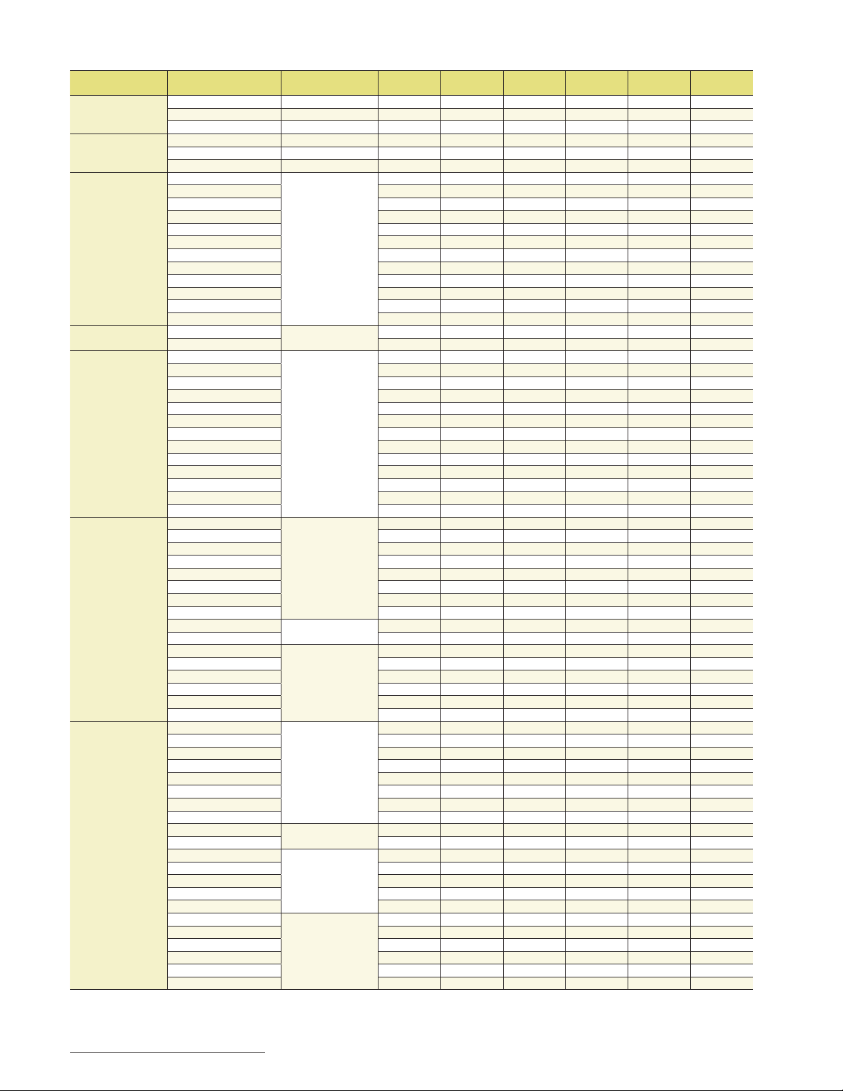
BVM-E / BVM-F Series Signal Formats / Input Adaptors
B/CR
B/CR
Standard
SDI Input
BKM-220D BKM-227W BKM-229X
O O O O
O O O
O O O
O O O
O O O
O O O
O O O
O O O
O O O
4
O*
4
4
O*
4
O*
4
4
O*
4
4
O*
O O
O O
4
O*
4
4
O*
4
4
O*
4
O*
4
O*
4
O*
4
O*
4
O*
4
O*
Input signal Signal system Signal format
Analog composite 487/59.94i NTSC O
576/50i PAL/SECAM O
487/59.94i PAL-M O
Analog Y/C 487/59.94i NTSC O
576/50i PAL/SECAM O
487/59.94i PAL-M O
Analog component, RGB 1080/60i*
1
1080/50i O
1080/24PsF*
1080/25PsF O
1080/30PsF*
1080/24p*
1080/25p O
1080/30p*
720/60p*
1
1
1
1
1
Y/PB/PR, RGB
720/50p O
576/50i O
487/59.94i O
SD-SDI 720 x 487/59.94i
720 x 576/50i O O O O
HD-SDI 1920 x 1080/24PsF*
1920 x 1080/25PsF O O O
1920 x 1080/30PsF*
1920 x 1080/24p*
1920 x 1080/25p O O O
1920 x 1080/30p*
1920 x 1080/50i O O O
1920 x 1080/60i*
1280 x 720/24p*
1280 x 720/25p O O O
1280 x 720/30p*
1280 x 720/50p O O O
1280 x 720/60p*
1
1
1
HD-SDI dual-link 1920 x 1080/24PsF*
1920 x 1080/25PsF O*
1920 x 1080/30PsF*
1920 x 1080/24p*
1920 x 1080/25p O*
1920 x 1080/30p*
1920 x 1080/50i O*
1920 x 1080/60i*
1920 x 1080/50p
1920 x 1080/60p*
2048 x 1080/24PsF*
2048 x 1080/24p*
2048 x 1080/25PsF*
2048 x 1080/25p*
2048 x 1080/30PsF*
2048 x 1080/30p*
3G-SDI 1920 x 1080/24PsF*
1920 x 1080/25PsF O*
1920 x 1080/30PsF*
1920 x 1080/24p*
1920 x 1080/25p O*
1920 x 1080/30p*
1920 x 1080/50i O*
1920 x 1080/60i*
1920 x 1080/50p
1920 x 1080/60p*
1280 x 720/24p*
1280 x 720/25p O*
1280 x 720/30p*
1280 x 720/50p O*
1280 x 720/60p*
1
1
1
2048 x 1080/24PsF*1*
2048 x 1080/24p*1*
2048 x 1080/25PsF*
2048 x 1080/25p*
2048 x 1080/30PsF*1*
2048 x 1080/30p*1*
1
1
1
1
1
1
1
1
1
1
1
1*3
1*3
3
3
1*3
1*3
1
1
1
1
1
1
3
3
3
3
3
3
4:2:2 Y/C
B/CR
10 bit 4:2:2 Y/CB/CR
10 bit 4:4:4 Y/CB/CR, RGB
12 bit 4:4:4 Y/C
B/CR, RGB
10 bit 4:2:2 Y/C
10 bit/12 bit 4:4:4 RGB
12 bit 4:4:4 XYZ
10 bit 4:4:4 Y/CB/CR, RGB
12 bit 4:4:4 Y/C
B/CR, RGB
10 bit 4:2:2 Y/C
10 bit 4:4:4 Y/CB/CR, RGB
10 bit/12 bit 4:4:4 RGB
12 bit 4:4:4 XYZ
*1 Also compatible with 1/1.001 frame rates. *2 Two BKM-243HS or BKM-244CC are used.
*3 Supported with the BVM-E250 and BVM-E170 only. *4 Untested.
O
O
O
O
O
O
BKM-243HS
BKM-244CC
2
O*
2
2
O*
2
O*
2
2
O*
2
2
O*
2
O*
2
O*
2
O*
2
O*
2
O*
2
O*
2
O*
2
O*
BKM-250TG
O
O
O
O
O
O
O
O
O
O
O
O
O
O
O
O
4
O*
4
O*
4
O*
4
O*
4
O*
4
O*
4
O*
4
O*
4
O*
4
O*
4
O*
4
O*
4
O*
4
O*
4
O*
4
O*
4
O*
4
O*
4
O*
26
Page 27
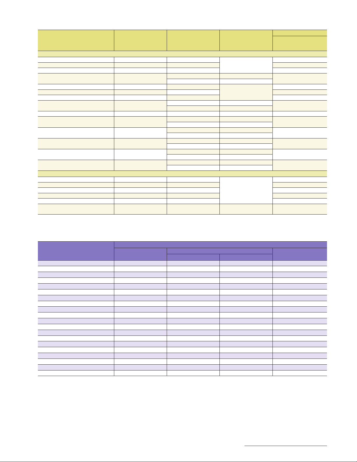
BVM-E / BVM-F Series HDMI Input Signal Formats
System
Interface sampling freq
(MHz)
Aspect Ratio Standard
Viedo Signals
640 x 480/60p* 25.200* 4:3
720 x 480/60p* 27.027* 4:3/16:9 O
CEA-861
1280 x 720/60p* 74.250* 16:9 O
1920 x 1080/60i* 74.250*
16:9 CEA-861
2.39:1
720 (1440) x 480/60i* 27.027* 4:3/16:9
720 x 576/50p 27.000* 4:3/16:9 O
CEA-861
1280 x 720/50p 74.250 16:9 O
1920 x 1080/50i 74.250
16:9 CEA-861
2.39:1
720 (1440) x 576/50i 27.000 4:3/16:9 CEA-861 O
1920 x 1080/60p* 148.500*
1920 x 1080/50p 148.500
1920 x 1080/24p* 74.250*
1920 x 1080/25p 74.250
1920 x 1080/30p* 74.250*
16:9 CEA-861
2.39:1
16:9 CEA-861
2.39:1
16:9 CEA-861
2.39:1
16:9 CEA-861
2.39:1
16:9 CEA-861
2.39:1
Computer Signals
800 x 600/60p 40.000 4:3
1024 x 768/60p 65.000 4:3 O
1280 x 960/60p 108.000 4:3 O
VESA
1280 x 1024/60p 108.000 5:4 O
1400 x 1050/60p 121.750 4:3 O
fH: 28-75 kHz, fV: 48-85 Hz
Max. res.: 1920 x 1080/60p
25.000-162.000
* Also compatible with 1/1.001 frame rates.
RGB 4:4:4 8/10/12 bit
B/CR 4:4:4 8/10/12 bit
Y/C
B/CR 4:2:2 12 bit
Y/C
HDMI
O
O
O
O
O
O
O
O
O
O
PVM-2541 / PVM-1741 / PVM-740 Signal Formats
Signal standard
System
575/50i (PAL) O O O O
480/60i (NTSC)*
576/50p – – – O
480/60p*
640 x 480/60p*
1080/24PsF*
1080/25PsF*
1080/30PsF*
1080/24p*
1080/25p – O*
1080/30p*
1080/50i – O*
1080/60i*
1080/50p – O*
1080/60p*
720/24p*
720/25p – O*
720/30p*
720/50p – O*
720/60p*
1
1
1
1*2
2
1*2
1
1
1
1
1
1
1
Analog composite
PVM-2541 / PVM-1741 PVM-740
O O O O
– – – O
– – – O
– O*
– O*
– O*
– O*
– O*
– O*
– O*
– O*
– O*
– O*
*1 Compatible with 1/1.001 frame rates.
*2 1080/24PsF, 2PsF, and 30PsF are displayed as 1080/48i, 0i, and 60i on the screen, respectively.
*3 10-bit 4:4:4 Y/C
*4 10-bit 4:2:2 Y/C
* 10-bit 4:4:4 Y/C
B/CR and 4:4:4 RGB of 3G-SDI signals are supported.
B/CR of 3G-SDI signal is supported.
B/CR of 3G-SDI signal is supported.
*6 PVM-241 and PVM-1741 can accept DVI signals via the HDMI interface using a conversion cable.
SDI (3G/HD/SD)
3
3
3
3
3
3
3
3
4
4
5
5
5
3
3
O –
O –
– –
O O
O O
O O
O O
O O
4
O*
4
O*
– –
– –
– –
O O*
O O*
HDMI
O*
O*
6
6
6
6
27
Page 28
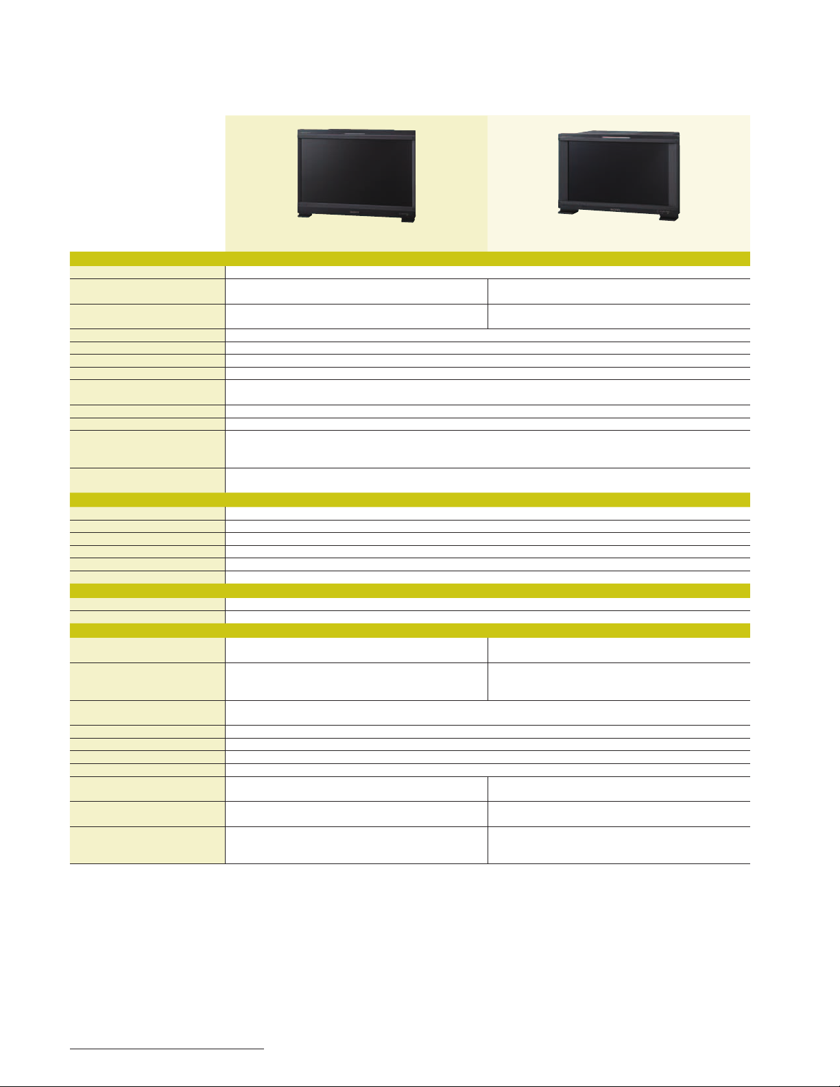
Specifications
BVM-E Series
BVM-E250 BVM-E170
Picture Performance
Panel OLED panel
Picture size (diagonal) 24 5/8 inches
Effective picture size (H x V) 21 1/2 x 12 1/8 inches
Resolution (H x V) 1920 x 1080 pixels (Full HD)
Aspect 16:9
Pixel efficiency 99.99%
Panel drive RGB 10-bit
Panel frame rate 48 Hz / 50 Hz / 60 Hz / 72 Hz / 75 Hz
Viewing angle (panel specification) 89°/89°/89°/89° (typical) (up/down/left/right contrast > 10:1)
Color temperature D55, D61, D65, D93, D-Cine, and user
Standard luminance 100 cd/m
Color space (color gamut) ITU-R BT.709, EBU, SMPTE-C, D-Cine*
Input
SDI BNC (x2)
HDMI HDMI (x1) (HDCP correspondence, Deep Color correspondence)
DisplayPort DisplayPort connector (x1)*
Option port 4 ports
Parallel remote D-sub 9-pin (female) (x1)
Serial remote (LAN) Ethernet (10BASE-T/100BASE-TX), RJ-45 (x1)
Output
SDI BNC (x1)
DC 5 V out Circle 4-pin (female) (x1)
General
Power requirement
Power consumption Approx. 145 W (max.)
Operating temperature 32°F to 95°F (0°C to 35°C)
Operating humidity 0% to 90% (no condensation)
Storage and transport temperature -4°F to +140°F (-20°C to +60°C)
Storage and transport humidity 0% to 90%
Operating, storage, and transport pressure 700 hPa to 1060 hPa
Dimensions (W x H x D) 22 3/4 x 16 3/4 x 5 7/8 inches
Weight 28 lb 11 oz
Supplied accessories
*1 Chromaticity point of SMPTE RP431-2 is not covered in full.
*2 The widest color space setting of the signal reproduced by the BVM-E250 and BVM-E170.
*3 S-GAMUT is available for displaying the color gamut of the wide color space mode S-GAMUT, which is offered with the F23 and F35 Digital cinematography
cameras.
*4 DisplayPort will be supported from the monitor firmware version 1.1 or later.
* Height without legs.
The BVM-E250 / BVM-E170 individual chromaticity points: R (x = 0.681, y = 0.319) / G (x = 0.189, y = 0.724) / B (x= 0.141, y= 0.051) (typical)
AC 100 V to 240 V, 1.6 A to 0.8 A, 50/60 Hz
(average power consumption in the default status)
AC power cord (1), AC plug holder (1), Bracket (1), Operation Manual
(Japanese, English, each 1), CD-ROM (1), Using the CD-ROM Manual (1)
623.4 mm
543.4 x 305.6 mm
(48 Hz, 60 Hz, and 72 Hz are also compatible with 1/1.001 frame rates)
Approx. 72 W
576.0 x 424.0 x 148.0 mm
13.0 kg
2
(preset1 to preset5)
2
(preset (D-Cine))
48 cd/m
(100% white signal input)
Recommended: 68°F to 86°F (20°C to 30°C)
1
, E250 / E170 Native*2, S-GAMUT*
4
AC 100 V to 240 V, 1.2 A to 0.7 A, 50/60 Hz
Approx. 110 W (AC), 100 W (DC) (max.)
(average power consumption in the default status)
17 1/4 x 11 1/4 (10 1/2)*
AC power cord (1), AC plug holder (1), Rack mount bracket (left, right, each 1),
Rack mount attachment screws (4), Operation Manual (Japanese, English,
each 1), CD-ROM (1), Using the CD-ROM Manual (1)
16 1/2 inches
419.7 mm
14 1/2 x 8 1/8 inches
365.8 x 205.7 mm
3
DC 24 V to 28 V, 4.5 A to 3.9 A
Approx. 60 W (AC), 60 W (DC)
436.0 x 282.4 (266.4)*
18 lb 15 oz
8.6 kg
5
x 8 1/2 inches
5
x 214.7 mm
28
Page 29
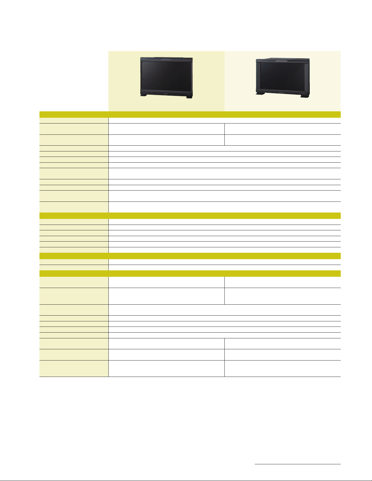
BVM-F Series
BVM-F250 BVM-F170
Picture Performance
Panel OLED panel
Picture size (diagonal) 24 5/8 inches
Effective picture size (H x V) 21 1/2 x 12 1/8 inches
Resolution (H x V) 1920 x 1080 pixels (Full HD)
Aspect 16:9
Pixel efficiency 99.99%
Panel drive RGB 10-bit
Panel frame rate 48 Hz / 50 Hz / 60 Hz / 72 Hz / 75 Hz
Viewing angle (panel specification) 89°/89°/89°/89° (typical) (up/down/left/right contrast > 10:1)
Color temperature D65, D93, and user
Standard luminance 100 cd/m
Color space (color gamut) ITU-R BT.709, EBU, SMPTE-C, F250 / F170 Native*
The BVM-F250 / BVM-F170 individual chromaticity points: R (x = 0.681, y = 0.319) / G (x = 0.189, y = 0.724) / B (x= 0.141, y= 0.051) (typical)
Input
SDI BNC (x2)
HDMI HDMI (x1) (HDCP correspondence, Deep Color correspondence)
DisplayPort DisplayPort connector (x1)*
Option port 4 ports
Parallel remote D-sub 9-pin (female) (x1)
Serial remote (LAN) Ethernet (10BASE-T/100BASE-TX), RJ-45 (x1)
Output
SDI BNC (x1)
DC 5 V out Circle 4-pin (female) (x1)
General
Power requirement
AC 100 V to 240 V, 1.6 A to 0.8 A, 50/60 Hz
Power consumption Approx. 145 W (max.)
(average power consumption in the default status)
Operating temperature 32°F to 95°F (0°C to 35°C)
Operating humidity 0% to 90% (no condensation)
Storage and transport temperature -4°F to +140°F (-20°C to +60°C)
Storage and transport humidity 0% to 90%
Operating, storage, and transport pressure 700 hPa to 1060 hPa
Dimensions (W x H x D) 22 3/4 x 16 3/4 x 5 7/8 inches
Weight 28 lb 11 oz
Supplied accessories
AC power cord (1), AC plug holder (1), Bracket (1), Operation Manual
(Japanese, English, each 1), CD-ROM (1), Using the CD-ROM Manual (1)
*1 The widest color space setting of the signal reproduced by the BVM-F250 and BVM-F170.
*2 DisplayPort will be supported from the monitor firmware version 1.1 or later.
*3 Height without legs.
623.4 mm
543.4 x 305.6 mm
(48 Hz, 60 Hz, and 72 Hz are also compatible with 1/1.001 frame rates)
Approx. 72 W
576.0 x 424.0 x 148.0 mm
13.0 kg
2
(Preset1 to Preset5)
(100% white signal input)
2
AC 100 V to 240 V, 1.2 A to 0.7 A, 50/60 Hz
Approx. 110 W (AC), 100 W (DC) (max.)
(average power consumption in the default status)
Recommended: 68°F to 86°F (20°C to 30°C)
17 1/4 x 11 1/4 (10 1/2)*
AC power cord (1), AC plug holder (1), Rack mount bracket (left, right, each 1),
Rack mount attachment screws (4), Operation Manual (Japanese, English,
each 1), CD-ROM (1), Using the CD-ROM Manual (1)
1
DC 24 V to 28 V, 4.5 A to 3.9 A
Approx. 60 W (AC), 60 W (DC)
436.0 x 282.4 (266.4)*
16 1/2 inches
419.7 mm
14 1/2 x 8 1/8 inches
365.8 x 205.7 mm
3
x 8 1/2 inches
3
x 214.7 mm
18 lb 15 oz
8.6 kg
29
Page 30
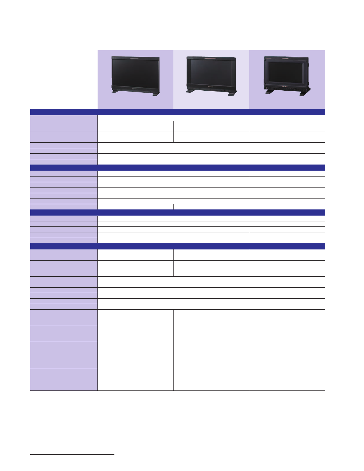
PVM Series
PVM-2541 PVM-1741 PVM-740
Picture Performance
Panel OLED panel
Picture size (diagonal) 24 5/8 inches
Effective picture size (H x V) 21 1/2 x 12 1/8 inches
Resolution (H x V) 1920 x 1080 pixels (Full HD) 960 x 540 pixels (QHD)
Aspect 16:9
Panel drive RGB 10-bit
Viewing angle (panel specification) 89°/89°/89°/89° (typical) (up/down/left/right contrast > 10:1)
Input
Composite BNC (x1), 1.0 Vp-p ±3 dB sync negative
SDI BNC (x2) BNC (x1)
HDMI HDMI (x1) (HDCP correspondence)
Audio Stereo mini jack (x1), -5 dBu 47 kilohms or higher
Parallel remote Modular connector 8-pin (x1) (pin-assignable)
Serial remote (LAN) RJ-45 modular connector (Ethernet) (x1) (10BASE-T/100BASE-TX)
DC IN connector – XLR-type 4-pin (male) (x1), 12 V DC (output impedance 0.05 ohms or less)
Output
Composite BNC (x1), loop-through, with 75 ohms automatic termination
SDI BNC (x1), output signal amplitude: 800 mVp-p ±10%, output impedance: 75 ohms unbalanced
Audio monitor out Stereo mini jack (x1)
Speaker (Built-in) 1.0 W (mono) 0.5 W (mono)
Headphones output Stereo mini jack (x1)
General
Power requirement
Power consumption Approx. 130 W (max.)
Operating temperature 32°F to 95°F (0°C to 35°C)
Operating humidity 30% to 85% (no condensation)
Storage and transport temperature -4°F to +140°F (-20°C to +60°C)
Storage and transport humidity 0% to 90%
Operating, storage, and transport pressure 700 hPa to 1060 hPa
Dimensions (W x H x D)
(with stand)
Dimensions (W x H x D)
(without stand)
Weight 23 lb 5.9 oz
Supplied accessories
AC 100 V to 240 V, 50/60 Hz, 1.4 A to 0.6 A
Approx. 88 W (average power consumption in
(with an optional SU-561 monitor stand)
AC power cord (1), AC plug holder (1),
Operating Instructions (1), CD-ROM (1),
623.4 mm
543.4 x 305.6 mm
the default status)
Recommended: 68°F to 86°F (20°C to 30°C)
22 3/4 x 16 3/4 x 6 3/4 inches
576.0 x 424.8 x 171.4 mm
22 3/4 x 16 1/8 x 4 3/8 inches
576.0 x 408.8 x 110.0 mm
10.6 kg
27 lb 16 oz
12.7 kg
Using the CD-ROM manual (1)
AC 100 V to 240 V, 50/60 Hz, 1.0 A to 0.5 A,
Approx. 90 W (AC power supply) (max.)
Approx. 70 W (AC power supply) (average power
(with an optional SU-561 monitor stand)
AC power cord (1), AC plug holder (1),
Mounting bracket (2) (including 4 screws),
Operating Instructions (1), CD-ROM (1),
16 1/2 inches
419.7 mm
14 1/2 x 8 1/8 inches
365.8 x 205.7 mm
DC 12 V, 7.0 A
consumption in the default status)
17 1/4 x 12 1/8 x 6 3/8 inches
436.0 x 305.6 x 161.0 mm
17 1/4 x 11 1/2 x 4 3/4 inches
436.0 x 289.6 x 120.0 mm
15 lb 14 oz
7.2 kg
20 lb 8 oz
9.3 kg
Using the CD-ROM manual (1)
7 1/2 inches
188.0 mm
6 1/2 x 3 5/8 inches
163.9 x 92.2 mm
AC 100 V to 240 V, 50/60 Hz, 0.5 A to 0.3 A,
DC 12 V, 1.9 A
Approx. 27 W (max.)
0°C to 40°C (32°F to 104°F)
Recommended: 68°F to 86°F (20°C to 30°C)
8 7/8 x 7 1/4 x 6 3/8 inches
222.4 x 183.5 x 161.8 mm
(when AC adaptor is attached)
8 7/8 x 6 5/8 x 2 7/8 inches
222.4 x 166 x 70 mm
(when AC adaptor is detached)
4 lb 6 oz
2.0 kg
5 lb 12 oz
2.6 kg
(When AC adaptor is installed)
AC power cord (1), AC plug holder (1),
AC power adaptor (1), Operating Instructions (1),
CD-ROM (1), Using the CD-ROM manual (1)
30
Page 31
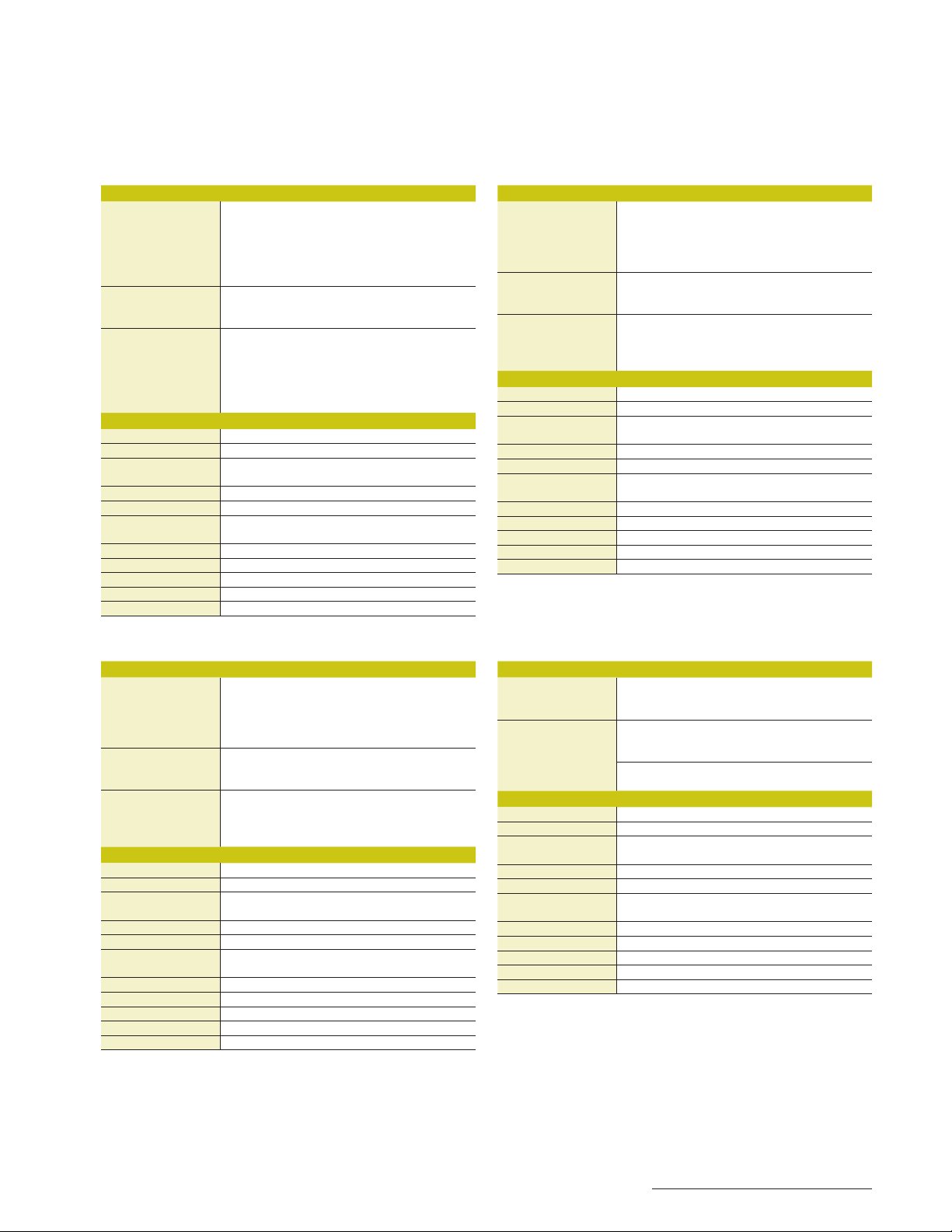
Optional Accessories
BKM-250TG
INPUT/OUTPUT
Serial digital interface BNC (x2),
Monitor out BNC (x2),
Transmission distance 3G-SDI: 70 m (approx. 230 ft) max.
GENERAL
Voltage +3.3 V, +5 V (supplied from the main unit)
Power consumption Approx. 4 W
Operating temperature 32°F to 95°F (0°C to 35°C)
Operating humidity 0% to 90% (no condensation)
Operating pressure 700 hPa to 1060 hPa
Storage and trans.
temperature
Storage and trans. humidity 0% to 90%
Storage and trans. pressure 700 hPa to 1060 hPa
Dimensions (W x H x D) 4 x 13/16 x 6 1/2 inches (100 x 20 x 162 mm)
Weight 270 g (270 g)
Supplied accessories Operating Instructions (1)
Digital component signals sampling frequency:
B/CR: 148.5 MHz/74.25 MHz/74.25 MHz,
3G-SDI: Y/C
G/B/R: 148.5 MHz/148.5 MHz/148.5 MHz
B/CR: 74.25 MHz/37.125 MHz/37.125 MHz,
HD-SDI: Y/C
(When using 5C-FB coaxial cables (Fujikura) or equivalent.)
(When using 5C-FB coaxial cables (Fujikura) or equivalent.)
(When using 5C-2V coaxial cables (Fujikura) or equivalent.)
B/CR: 13.5 MHz/6.75 MHz/6.75 MHz
SD-SDI: Y/C
Output signal amplitude: 800 mVp-p ±10%
Output impedance: 75 ohms unbalanced
HD-SDI: 100 m (approx. 328 ft) max.
SD-SDI: 200 m (approx. 656 ft) max.
Recommended: 68°F to 86°F (20°C to 30°C)
-4°F to +140°F (-20°C to +60°C)
BKM-244CC
INPUT/OUTPUT
Serial digital interface BNC (x2),
Monitor out BNC (x1),
Transmission distance SD-SDI: 200 m (approx. 656 ft) max.
GENERAL
Voltage +3.3 V, +5 V (supplied from the main unit)
Power consumption Approx. 4 W
Operating temperature 32°F to 95°F (0°C to 35°C)
Operating humidity 0% to 90% (no condensation)
Operating pressure 700 hPa to 1060 hPa
Storage and trans.
temperature
Storage and trans. humidity 0% to 90%
Storage and trans. pressure 700 hPa to 1060 hPa
Dimensions (W x H x D) 4 x 13/16 x 6 1/2 inches (100 x 20 x 162 mm)
Weight 9 oz (250 g)
Supplied accessories Operating Instructions (1)
Digital component signals sampling frequency:
SD-SDI: Y/R-Y/B-Y: 13.5 MHz,
B/CR: 74.25 MHz
HD-SDI: Y/C
Quantization: 10 bits/sample
Output signal amplitude: 800 mVp-p ±10%
Output impedance: 75 ohms unbalanced
(when using 5C-2V coaxial cables (Fujikura) or equivalent)
HD-SDI: 100 m (approx. 328 ft) max.
(when using 5C-FB coaxial cables (Fujikura) or equivalent)
Recommended: 68°F to 86°F (20°C to 30°C)
14°F to 104°F (-10°C to +40°C)
BKM-243HS
INPUT/OUTPUT
Serial digital interface BNC (x2),
Monitor out BNC (x1),
Transmission distance SD-SDI: 200 m (approx. 656 ft) max.
GENERAL
Voltage +3.3 V, +5 V (supplied from the main unit)
Power consumption Approx. 2 W
Operating temperature 32°F to 95°F (0°C to 35°C)
Operating humidity 0% to 90% (no condensation)
Operating pressure 700 hPa to 1060 hPa
Storage and trans.
temperature
Storage and trans. humidity 0% to 90%
Storage and trans. pressure 700 hPa to 1060 hPa
Dimensions (W x H x D) 4 x 13/16 x 6 1/2 inches (100 x 20 x 162 mm)
Weight Approx. 9 oz (250 g)
Supplied accessories Operating Instructions (1)
Digital component signals sampling frequency:
SD-SDI: Y/R-Y/B-Y: 13.5 MHz,
B/CR: 74.25 MHz
HD-SDI: Y/C
Quantization: 10 bits/sample
Output signal amplitude: 800 mVp-p ±10%
Output impedance: 75 ohms unbalanced
(when using 5C-2V coaxial cables (Fujikura) or equivalent)
HD-SDI: 100 m (approx. 328 ft) max.
(when using 5C-FB coaxial cables (Fujikura) or equivalent)
Recommended: 68°F to 86°F (20°C to 30°C)
-4°F to +140°F (-20°C to +40°C)
BKM-229X
INPUT/OUTPUT
RGB / Component
External sync input BNC (x1),
GENERAL
Voltage +3.3 V, +5 V (supplied from the main unit)
Power consumption Approx. 4 W
Operating temperature 0°C to 35°C (32°F to 95°F)
Operating humidity 0% to 90% (no condensation)
Operating pressure 700 hPa to 1060 hPa
Storage and trans.
temperature
Storage and trans. humidity 0% to 90%
Storage and trans. pressure 700 hPa to 1060 hPa
Dimensions (W x H x D) 4 x 13/16 x 6 1/2 inches (100 x 20 x 162 mm)
Weight 9 oz (250 g)
Supplied accessories Operating Instructions (1)
RGB: 0.7 Vp-p ±3 dB (Sync on Green, 0.3 Vp-p sync negative)
0.3 Vp-p to 4 Vp-p ± bipolarity ternary or negative polarity
Loop-through, with 75 ohms automatic termination
Recommended: 20°C to 30°C (68°F to 86°F)
-4°F to +140°F (-20°C to +60°C)
BNC (x3)
Component: 0.7 Vp-p ±3 dB
binary
Mini DIN 4-pin (x1),
31
Page 32
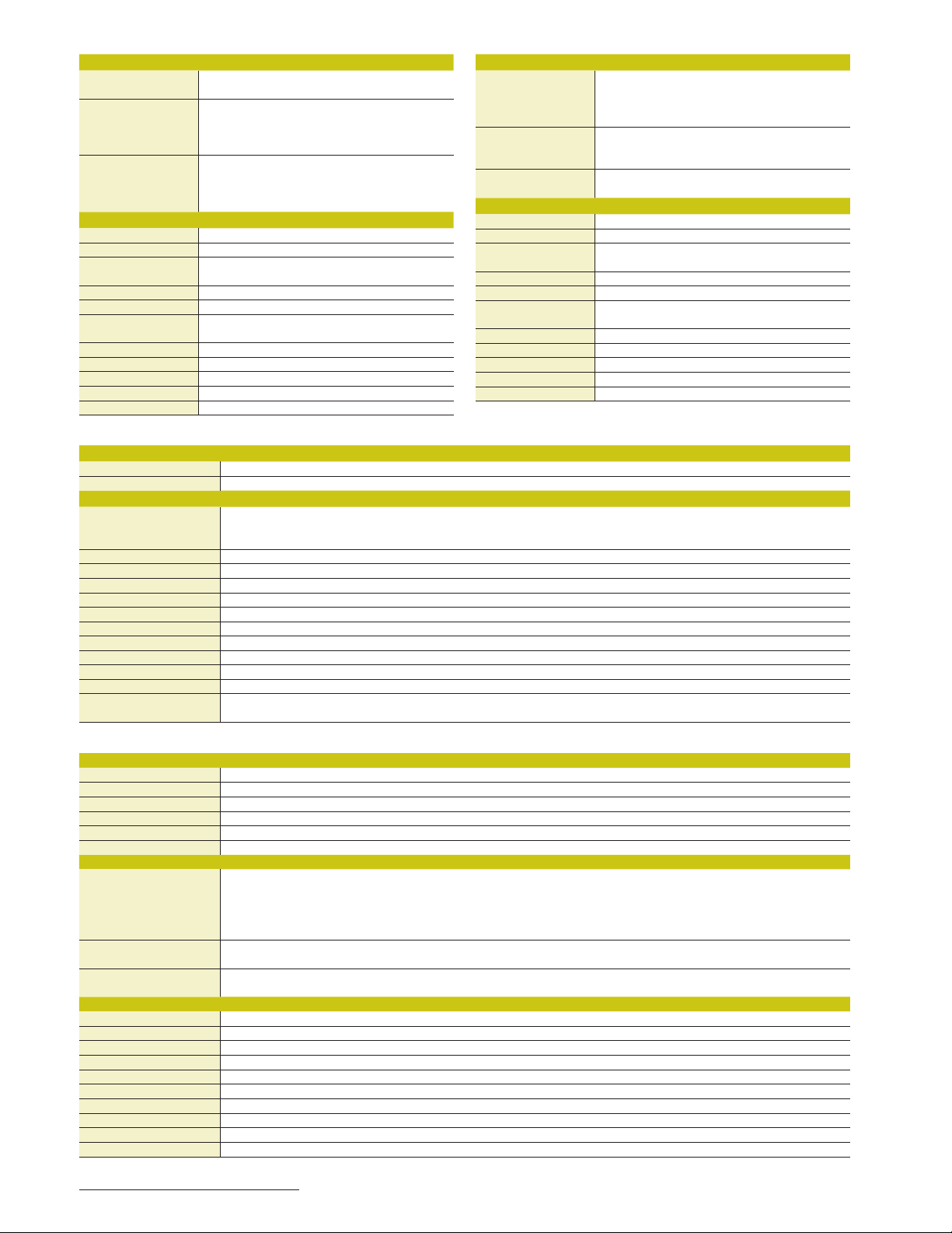
BKM-227W
INPUT/OUTPUT
Composite input BNC (x1),
Y/C input Mini DIN 4-pin (x1)
Monitor out BNC (x1),
GENERAL
Voltage +3.3 V, +5 V (supplied from the main unit)
Power consumption Approx. 1.8 W
Operating temperature 32°F to 95°F (0°C to 35°C)
Operating humidity 0% to 90% (no condensation)
Operating pressure 700 hPa to 1060 hPa
Storage and trans.
temperature
Storage and trans. humidity 0% to 90%
Storage and trans. pressure 700 hPa to 1060 hPa
Dimensions (W x H x D) 4 x 13/16 x 6 1/2 inches (100 x 20 x 162 mm)
Weight 8 oz (240 g)
Supplied accessories Operating Instructions (1)
1 Vp-p ±3 dB sync negative
Y: 1 Vp-p ±3 dB sync negative
C: 0.286 Vp-p ±3 dB (NTSC burst signal level),
0.3 Vp-p ±3 dB (PAL, PAL-M burst signal level)
Loop-through, with 75 ohms automatic termination
Mini DIN 4-pin (x1),
Loop-through, with 75 ohms automatic termination
Recommended: 68°F to 86°F (20°C to 30°C)
-4°F to +140°F (-20°C to +60°C)
BKM-220D
INPUT/OUTPUT
Serial digital interface BNC (x2),
Monitor out BNC (x1),
Transmission distance 200 m (approx. 656 ft) max.
GENERAL
Voltage +5 V (supplied from the main unit)
Power consumption Approx. 1.5 W
Operating temperature 32°F to 95°F (0°C to 35°C)
Operating humidity 0% to 90% (no condensation)
Operating pressure 700 hPa to 1060 hPa
Storage and trans.
temperature
Storage and trans. humidity 0% to 90%
Storage and trans. pressure 700 hPa to 1060 hPa
Dimensions (W x H x D) 4 x 13/16 x 6 1/2 inches (100 x 20 x 162 mm)
Weight 9 oz (250 g)
Supplied accessories Operating Instructions (1)
Digital component signals sampling frequency:
Y/R-Y/B-Y: 13.5 MHz
Quantization: 10 bits/sample
Output signal amplitude: 800 mVp-p ±10%
Output impedance: 75 ohms unbalanced
(when using 5C-2V coaxial cables (Fujikura) or equivalent)
Recommended: 68°F to 86°F (20°C to 30°C)
-4°F to +140°F (-20°C to +60°C)
BKM-16R
INPUT/OUTPUT
LAN 10BASE-T/100BASE-TX connector: RJ-45 (x1)
DC 5 V / 12 V IN Circle 4-pin (male) (x1)
GENERAL
Power requirements DC IN: 5 V, 1.1 A (supplied by the connected monitor)
Current consumption 5 V DC, 1.1 A / 12 V DC, 0.5 A
Power consumption Approx. 6 W
Operating temperature 32°F to 95°F (0°C to 35°C), Recommended: 68°F to 86°F (20°C to 30°C)
Operating humidity 0% to 90% (no condensation)
Operating pressure 700 hPa to 1060 hPa
Storage and trans. temperature 14°F to 104°F (-10°C to +40°C)
Storage and trans. humidity 0% to 90%
Storage and trans. pressure 700 hPa to 1060 hPa
Dimensions (W x H x D) 16 3/4 x 2 3/8 x 7 inches (424 x 58.8 x 174.9 mm)
Weight 4 lb 10 oz (2.1 kg)
Supplied accessories AC adaptor (1), AC power cord (parts number: 1-757-562-1x1 for USA and Canada, 1-575-131-8x for Europe) (1), Rack mount brackets (2),
DC IN: 12 V, 0.5 A (supplied by the connected AC adaptor)
AC adaptor: AC IN: 100 V to 240 V, 50/60 Hz, DC OUT: 12 V, 3 A
Rack mount attachment screws (4), Function labels (2), Operation manual (1)
VMM 4SNY-3GB
Analysis Functions
Waveform monitor Includes cursors, vertical and horizontal sweeps, line select, bowtie, and lowpass lters
Vectorscope 75% and 100% display, Line select, gain, zoom, and cursors
Gamut display As composite or RGB grids, line select, upper and lower alarms
Picture display With line select
Audio display 16 channel display as bar, lissajous, , 5.1 or 7.1 displays, phase, and selection of levels
Alarms Alarm log
Inputs
Serial digital interface BNC (x2) terminating 75Ω
AES/EBU BNC (x1) terminating 75Ω
Reference BNC (x1) terminating 75Ω
GENERAL
Voltage +3.3V, +5V (supplied from main unit)
Power consumption Approx. 12W
Operating temperature 0° to +35°C
Operating humidity 30% to 80% non-condensing
Operation pressure 700 hPa to 1060 hPa
Storage and trans temperature -20° to +60°C
Storage and trans humidity 5% to 90% non-condensing
Dimensions (W x H x D) 7.9 x 0.77 x 6.3 in (200.1 x 19.6 x 160.8mm)
Weight 1.30 lbs. (0.59kg)
Supplied Accessories CD with operating instructions
SD-SDI: Y/R-Y/B-Y: 13.5MHz/6.75MHz/6.75MHz
HD-SDI: Y/Cb/Cr: 74.25MHz/37.125MHz/37.125MHz
3G-SDI: Y/Cb/Cr: 148.5MHz/74.25MHz/74.25MHz
G/B/R: 148.5MHz/148.5MHz/148.5MHz
32kHz, 44.1kHz, 48kHz, 88.2kHz, 96kHz
Analog Black Burst as NTSC or PAL
32
Page 33
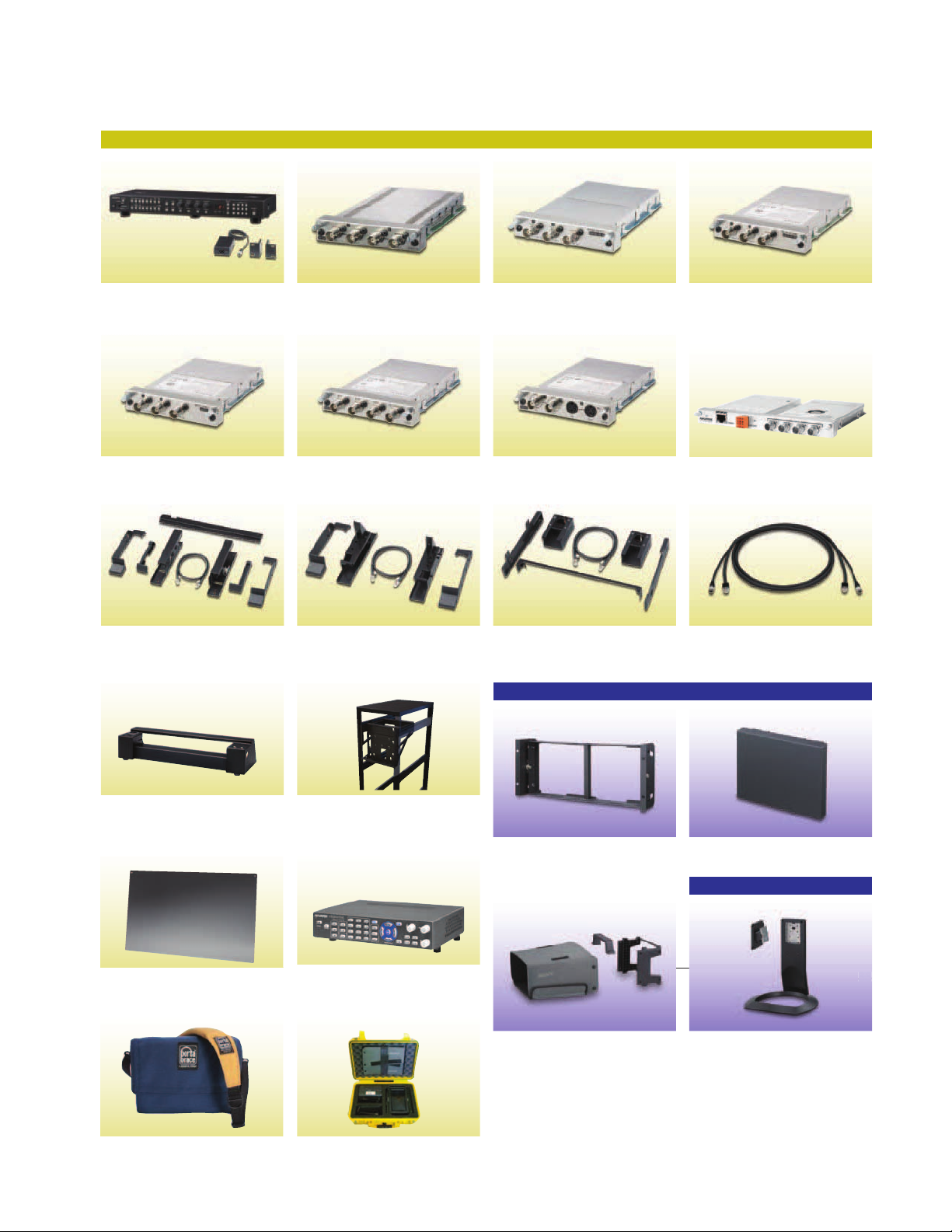
33
Optional Accessories
For BVM-E250, BVM-E170, BVM-F250, and BVM-F170
BKM-16R/7
Monitor Control Unit
BKM-220D
SD-SDI 4:2:2 Input Adaptor
BKM-37H
Controller Attachment Stand
(for BVM-E20 / BVM-F20)
BKM-250TG
3G/HD/SD-SDI Input Adaptor
BKM-229X
Analog Component Adaptor
BKM-38H
Controller Attachment Stand
(for BVM-E20 / BVM-F20)
BKM-244CC
HD/SD-SDI Closed Caption Adaptor
BKM-227W
NTSC/PAL Input Adaptor
BKM-39H
Controller Attachment Stand
(for BVM-E170 / BVM-F170)
For PVM-740
BKM-243HS
HD/SD-SDI Input Adaptor
VMM-4SNY
Integrated Test and Measurement Module
SMF-700
Monitor Interface Cable
PRK-37PM
Table Top Mounting Attachment Kit
(for attaching the BKM 16R and RCU-
CMS to a BVM-E250 or BVM-F250)
PRK-25PM
Protection Panel
(for BVM-E250 and BVM-F250)
LCPVM02KH
Portabrace Monitor Soft Case
(for LMD-940W / PVM-740)
PRK-2500PM
Rack Kit
(for BVM-E250 and BVM-F250)
RCU-CMS
Control panel for VMM-4SNY
PVMLMDFIELDKT
Field Kit consists of case, arm,
hood and quick release
(for PVM-740 / LMD-940W)
Monitor not included.
MB-531
Mounting Bracket
VF-510
ENG Kit (Viewing Hood, Carrying
Handle and Connector Protector)
MB-532
Mounting Panel
For PVM-2541 and PVM-1741
33
SU-561
Monitor Stand
Page 34
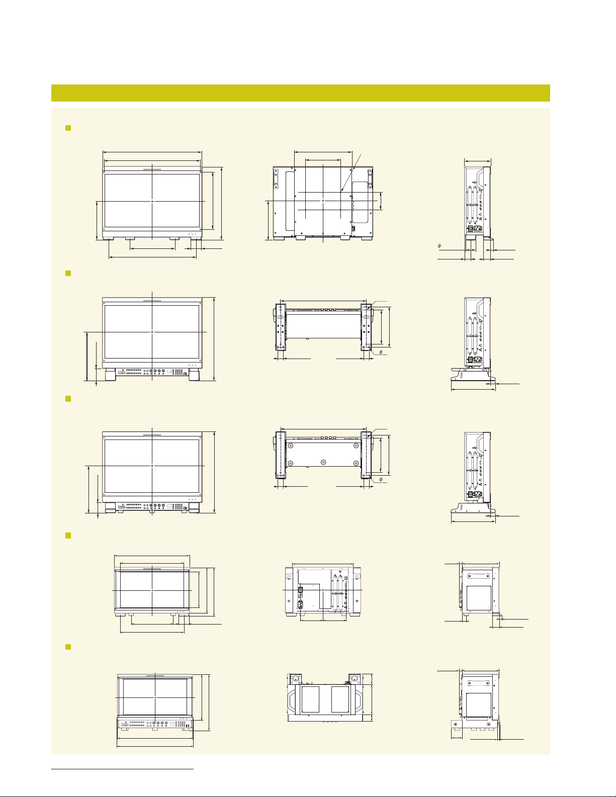
Dimensions
BVM-E Series
BVM-E250 / BVM-F250
Front Rear Side
9 (226)
22 3/4 (576)
21 3/4 (551)
10 (2 54)
20 (508)
/8 (3 31)
3
1
13
2 3/8 (60)
/4 (424)
16
9 (226)
BVM-E250 / BVM-F250 with the optional BKM-16R and BKM-37H with a tilt
Front Bottom Side
/8 (48 3.7 )
1
/4 (285.7)
1
3 (75.7)
11
19
BVM-E250 / BVM-F250 with the optional BKM-16R and BKM-38H
Front Bottom Side
3
1
13 1/4 (334.2)
/16 (30)
7 7/8 (200)
3
/8 (489. 8)
19
3
/8 (489. 8)
19
M4
1 3/16 (30)
4-M5
6- 8
4-M5
Unit: inches (mm)
5 7/8 (148)
4 (10 0)
2 1/4 (55)
1 3/8 (34.4)
/4 (195 )
/8 (230)
3
1
7
9
10 1/2 (266)
19
/32 (15)
1 5/8 (40)
3
1
/16 (30)
/4 (195 )
/8 (230)
3
1
7
/8 (469.6)
5
/2 (61.6 )
1
/4 (271.6)
3
2
10
19
1
3
/16 (30)
1 3/16 (30)
9
6- 8
BVM-E170 / BVM-F170
Front Rear Side
17 1/4 (436)
14 1/2 (365.8)
9 5/8 (244)
14 1/2 (368)
/8 (205.7)
1
8
3
2
/8 (59.95)
/2 (266.4)
/8 (282.4)
1
1
10
11
13
5 1/4
(131)
7
/8 (352)
(134.6)
5 3/8
BVM-E170 / BVM-F170 with the optional BKM-16R and BKM-39H
Front Bottom Side
/2 (62.3)1
1
2
/2 (266.4)
/8 (325.2)
1
1
/4 (438)
17
17 1/2 (443)
7
10
12
7 (175)
/8 (40)
5
11
/16 (17)
15
/16 (23.3)
11
/16 (17)
2 1/2
(62.3)
1
10
/2 (266)
8 1/2 (215)
8 1/2 (215)
11
/32 (8.7)
3
1
/16 (30)
19
1 5/8 (40)
3
/16 (4.4)
/32 (14.7)
34
Page 35
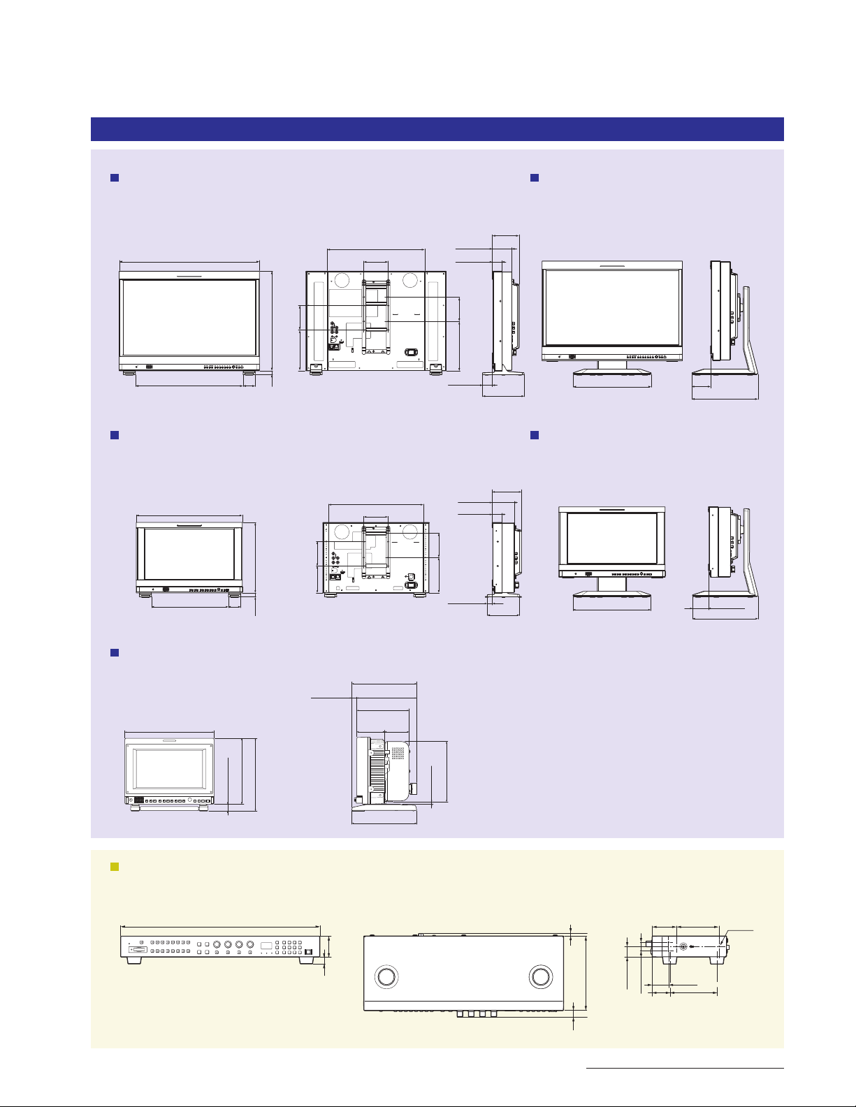
PVM Series
PVM-2541
Front FrontRear Side Side
15 3/4 (400)
22 3/4 (576)
17 1/2 (442)
(50)
/8 (408.8)
1
16
/8 (167.6) 4 (100)
5
/32 (16)
21
6
2
4 (100)
3 1/4 (80)
1 5/8 (40)
4
8 (202.6)
5
/8 (40)
1
(100)
4 3/8 (110)
6 3/4
(171.4)
PVM-2541
with the optional SU-561 stand
12 5/8 (320)
Unit: inches (mm)
3
(76.2)
10 3/4
(269.9)
PVM-1741
PVM-1741
with the optional SU-561 stand
Front FrontRear Side Side
4 3/4 (120)
4
/4
3
5
3 5/8 (90)
1 5/8 (40)
(100)
(145.4)
7
1
/16 (35)
6 3/8
(161)
12 5/8 (320)
17 1/4 (436)
12 3/4 (322)
(50)
15 3/8 (389.6)
4 (100)
/2 (289.6)
1
11
/8 (110.4) 4 (100)
2
/32
(16)
21
3
4
PVM-740
3
/8 (161.8)
Front Side
8 7/8 (222.4)
(166)
(183.5)
8
/
4
(17.5)
/
5
1
32
6
/
7
23
17
/32 (13)
6
5 7/8 (148.8)
5 1/8 (130)
2
2 7/
8
(70)
(60)
6 3/8 (161.5)
3
/
8
6 (149.6)
(5.6)
4
/
1
2
5
/8 (66)
10 3/4
(269.9)
BKM-16R
Front Top Side
16 3/4 (424)
(14.8)
32
/
19
(44)
/
3
1
4
7
/32 (5.3)
17
/32 (13.1)
(156.5)
4
/
1
6
7
2 1/8 (51.5) 3
(18)
(22)
32
/
8
/
23
1 1/2 (37)
Unit: inches (mm)
5
3
1
/8 (34.5)
4 (99.5)
/8 (90)
4-M4
35
Page 36

Sony Electronics Inc.
1 Sony Drive
Park Ridge, NJ 07656
sony.com/trimasterel
DI-0232-B (MK10815V4)
The BVM-E250, BVM-E170, BVM-F250, and BVM-F170
are produced at Sony EMCS Corporation Tokai
Tec, which has received ISO14001 Environmental
Management System certification.
The PVM-2541, PVM-1741, and PVM-740 are produced
under control of the Sony EMCS Corporation Tokai Tec.
Reproduction in whole or in part without written permission is prohibited.
©2012 Sony Electronics Inc. All rights reserved.
Features and specifications are subject to change without notice.
Screen images are simulated.
Sony, ChromaTRU, Trimaster, TRIMASTER EL, Betacam, Memory Stick,
Memory Stick PRO, Memory Stick Duo, Memory Stick PRO Duo, Memory
Stick Micro and the Sony make.believe logo are trademarks of Sony.
HDMI is a trademark of HDMI Licensing, LLC.
All other trademarks are the trademarks of their respective owners.
Printed in USA (8/12)
 Loading...