

Sony SSM-14N5E, SSM-20N5A, SSM-14N5U, SSM-14N5A, SSM-20N5E User Manual
...
SERVICE MANUAL
SIIA
CHASSIS
MODEL
…………… ……… …………………
PVM-14N5A
PVM-14N5E
PVM-14N5MDE
PVM-14N5U
PVM-14N6A
PVM-14N6E
PVM-14N6U
SSM-14N5A
SSM-14N5E
SSM-14N5U
DEST . CHASSIS NO.
AUS SCC-N87D-A
AEP SCC-N86C-A
AEP SCC-N86F-A
US/CND SCC-N84B-A
AUS SCC-N87C-A
AEP SCC-N86B-A
US/CND SCC-N84A-A
AUS SCC-N87A-A
AEP SCC-N86A-A
US/CND SCC-N84E-A
MODEL
…………… ……… …………………
PVM-20N5A
PVM-20N5E
PVM-20N5U
PVM-20N6A
PVM-20N6E
PVM-20N6U
SSM-20N5A
SSM-20N5E
SSM-20N5U
DEST . CHASSIS NO.
AUS SCC-N87F-A
AEP SCC-N86E-A
US/CND SCC-N84D-A
AUS SCC-N87E-A
AEP SCC-N86D-A
US/CND SCC-N84C-A
AUS SCC-N87B-A
AEP SCC-N86G-A
US/CND SCC-N84F-A
TRINITRON® COLOR VIDEO MONITOR
! W ARNING
This manual is intended for qualified service personnel
only .
T o reduce the risk of electric shock, fire or injury , do not
perform any servicing other than that contained in the
operating instructions unless you are qualified to do so.
Refer all servicing to qualified service personnel.
(PVM-14N5MDE only)
Electromagnetic
Compatibility
This device compiles with the requirements of Directive 89/336/EEC
concerning electromagnetic compatibility.
This device meets EN50081-1/92 and EN50082-1/92.
WARNING!!
AN ISOLATION TRANSFORMER SHOULD BE USED DURING ANY
SERVICE TO AVOID POSSIBLE SHOCK HAZARD, BECAUSE OF
LIVE CHASSIS.
THE CHASSIS OF THIS RECEIVER IS DIRECTL Y CONNECTED TO
THE AC POWER LINE.
SAFETY-RELATED COMPONENT WARNING!!
COMPONENTS IDENTIFIED BY MARK
DIAGRAMS, EXPLODED VIEWS AND IN THE PARTS
LIST ARE CRITICAL TO SAFE OPERATION. REPLACE THESE
COMPONENTS WITH SONY PARTS WHOSE PART NUMBERS
APPEAR AS SHOWN IN THIS MANUAL OR IN SUPPLEMENTS
PUBLISHED BY SONY. CIRCUIT ADJUSTMENTS THAT ARE
CRITICAL TO SAFE OPERATION ARE IDENTIFIED IN THIS
MANUAL. FOLLO W THESE PR OCEDURES WHENEVER CRITICAL
COMPONENTS ARE REPLACED OR IMPROPER OPERATION IS
SUSPECTED.
!!
! ON THE SCHEMATIC
!!
ATTENTION!!
AFIN D’EVITER T OUT RISQUE D’ELECTROCUTION PR OVENANT
D’UN CHÁSSIS SOUS TENSION, UN TRANSFORMATEUR
D’ISOLEMENT DOIT ETRE UTILISÉ LORS DE TOUT DÉPANNAGE.
LE CHÁSSIS DE CE RÉCEPTEUR EST DIRECTEMENT
RACCORDÉ À L’ALIMENT ATION SECTEUR.
A TTENTION AUX COMPOSANTS RELATIFS À LA
SÉCURITÉ!!
LES COMPOSANTS IDENTIFIÈS PAR UNE TRAME ET PAR UNE
MARPUE
EXPLOSÉES ET LES LISTES DE PIECES CONT D’UNE
IMPORTANCE CRITIQUE PUR LA SÉCURITÉ DU
FONCTIONNEMENT. NE LES REMPLACER QUE PAR DES
COMPOSANTS SONY DONT LE NUMÉRO DE PIÉCE EST INDIQUÉ
DANS LE PRÉSENT MANUEL OU DANS DES SUPPLÉMENTS
PUBLIÉS PAR SONY. LES RÉGLAGES DE CIRCUIT DONT
L’IMPORTANCE EST CRITIQUE POUR LA SÉCURITÉ DU
FONCTIONNEMENT SONT IDENTIFIES DANS LE PRÉSENT
MANUEL. SUIVRE CES PROCÉDURES LORS DE CHAQUE
REMPLACEMENT DE COMPOSANTS CRITIQUES, OU
LORSQU’UN MAUVAIS FONCTIONNEMENT EST SUSPECTÉ.
!!
! SUR LES SCHÉMAS DE PRINCIPE, LES VUES
!!

TABLE OF CONTENTS
1. OPERATING INSTRUCTIONS
1-1. PVM-14N5/14N6 (A/E/U), PVM-20N5/20N6 (A/E/U) ................................ 1-1
1-2. PVM-14N5MDE ............................................................................................ 1-9
1-3. SSM-14N5 (A/E/U), SSM-20N5 (A/E/U) ................................................... 1-18
2. SERVICE INFORMATION
2-1. CIRCUIT BOARDS LOCATION ................................................................. 2-1
2-2. DISASSEMBLY ............................................................................................ 2-2
2-2-1. Cabinet Removal .................................................................................... 2-2
2-2-2. A Board Removal ................................................................................... 2-2
2-2-3. Service Position ...................................................................................... 2-2
2-2-4. Picture Tube Removal ............................................................................ 2-3
2-2-5. Removal of Anode-cap...........................................................................2-4
3. SET-UP ADJUSTMENTS
3-1. PREPARATIONS (1)..................................................................................... 3-1
3-2. PREPARATIONS (2)..................................................................................... 3-4
3-3. OUTPUTTING IMAGES .............................................................................. 3-4
3-4. RASTER CENTERING ADJUSTMENT ...................................................... 3-4
3-5. LANDING ADJUSTMENT........................................................................... 3-5
3-6. CONVERGENCE ADJUSTMENT ............................................................... 3-6
3-7. INCLINATION OF DEFLECTION YOKE ADJUSTMENT ....................... 3-7
3-8. G2 ADJUSTMENT ........................................................................................ 3-8
3-9. WHITE BALANCE ADJUSTMENTS .......................................................... 3-8
3-9-1. VIDEO (Except SECAM) Adjustment .................................................. 3-8
3-9-2. Analog RGB Adjustment (PVM-14N6A, PVM-14N6E, PVM-14N6U,
PVM-20N6E, PVM-20N6U).................................................................. 3-9
3-9-3. SECAM Cut-off Adjustment ................................................................ 3-10
3-9-4. Sub-Brightness Adjustment.................................................................. 3-10
3-10.FOCUS ADJUSTMENT .............................................................................. 3-10
4. SAFETY RELATED ADJUSTMENTS
4-1. B+ VOLTAGE CHECK ................................................................................ 4-1
4-2. PROTECTION CIRCUIT (HOLD-DOWN CIRCUIT) CHECK .................. 4-2
SIIA Chassis
5. CIRCUIT ADJUSTMENTS
5-1. PREPARATIONS .......................................................................................... 5-1
5-2. DEFLECTION SYSTEM ADJUSTMENT ................................................... 5-1
5-2-1. Vertical Deflection Section Adjustment................................................. 5-1
5-2-2. Horizontal Deflection Section Adjustment ............................................ 5-1
5-2-3. Horizontal Centering Adjustment...........................................................5-2
1

6. SEMICONDUCTORS
7. EXPLODED VIEWS
7-1. CHASSIS (14-INCH) ..................................................................................... 7-2
7-2. CHASSIS (20-INCH) ..................................................................................... 7-3
8. ELECTRICAL PARTS LIST
9. BLOCK DIAGRAMS
10. DIAGRAMS
10-1.FRAME SCHEMATIC DIAGRAMS ..........................................................10-1
10-2.SCHEMATIC DIAGRAMS/PRINTED WIRING BOARDS .....................10-1
SCHEMATIC DIAGRAMS
A (1/2) Board ..................................................................................................... 10-4
A (2/2) Board ..................................................................................................... 10-6
CA Board ...........................................................................................................10-8
CB Board............................................................................................................10-9
Q Board ............................................................................................................10-11
PRINTED WIRING BOARDS
A Board ..............................................................................................................10-2
CA Board ...........................................................................................................10-8
CB Board............................................................................................................10-9
Q Board ............................................................................................................10-10
2
SIIA Chassis
SIIA Chassis
Trinitron
®
Color Video Monitor
3-864-157-11(2)
PVM-14N5A/14N5E/14N5U
PVM-14N6A/14N6E/14N6U
PVM-20N5A/20N5E/20N5U
PVM-20N6A/20N6E/20N6U
Operating Instructions
Page 2
Mode d’emploi
Page 16
Bedienungsanleitung
Seite 30
Manual de instrucciones
Página 44
Istruzioni per l’uso
Pagina 58
######
72
EN
F
D
1998 by Sony Corporation
E
I
C
1-1. PVM-14N5/14N6 (A/E/U), PVM-20N5/20N6 (A/E/U)
OPERATING INSTRUCTIONS
1-1
SECTION 1
This section is extracted
from operating instructions

1-2
2
English
Owner’s Record
The model and serial numbers are located at the rear.
Record these numbers in the spaces provided below.
Refer to these numbers whenever you call upon your
Sony dealer regarding this product.
Model No.
Serial No.
WARNING
To prevent fire or shock hazard, do not
expose the unit to rain or moisture.
Dangerously high voltage are present
inside the unit.
Do not open the cabinet. Refer servicing
to qualified personnel only.
In the event of a malfunction or when maintenance is
necessary, consult an authorized Sony dealer.
For the customers in the U.S.A.
This equipment has been tested and found to comply with
the limits for a Class A digital device, pursuant to Part 15 of
the FCC Rules. These limits are designed to provide
reasonable protection against harmful interference when the
equipment is operated in a commercial environment.
This equipment generates, uses, and can radiate radio
frequency energy and, if not installed and used in
accordance with the instruction manual, may cause harmful
interference to radio communications. Operation of this
equipment in a residential area is likely to cause harmful
interference in which case the user will be required to correct
the interference at his own expense.
You are cautioned that any changes or modifications not
expressly approved in this manual could void your authority
to operate this equipment.
For the customers in the United Kingdom
WARNING
THIS APPARATUS MUST BE EARTHED
IMPORTANT
The wires in this mains lead are coloured in accordance with
the following code:
Green-and-yellow: Earth
Blue: Neutral
Brown: Live
As the colours of the wires in the mains lead of this
apparatus may not correspond with the coloured markings
identifying the terminals in your plug proceed as follows:
The wire which is coloured green-and-yellow must be
connected to the terminal in the plug which is marked by the
letter E or by the safety earth symbol Y or coloured green or
green-and-yellow.
The wire which is coloured blue must be connected to the
terminal which is marked with the letter N or coloured black.
The wire which is coloured brown must be connected to the
terminal which is marked with the letter L or coloured red.
Ensure that your equipment is connected correctly - If you
are in any doubt consult a qualified electrician.
ATTENTION:
Picture distortion may occur if this monitor is positioned
in close proximity to any equipment emitting
electromagnetic radiation.
3
On safety
•Operate the unit only with a power source as
specified in “Specifications” section.
•The nameplate indicating operating voltage, power
consumption, etc., is located at the rear.
•Should any solid object or liquid fall into the cabinet,
unplug the unit and have it checked by qualified
personnel before operating it any further.
•Do not drop or place heavy objects on the power
cord. If the power cord is damaged, turn off the
power immediately. It is dangerous to use the unit
with a damaged power cord.
•Unplug the unit from the wall outlet if it is not to be
used for several days or more.
•Disconnect the power cord from the AC outlet by
grasping the plug, not by pulling the cord.
•The socket-outlet shall be installed near the
equipment and shall be easily accessible.
On installation
•Allow adequate air circulation to prevent internal heat
build-up.
Do not place the unit on surfaces (rugs, blankets, etc.)
or near materials (curtains, draperies) that may block
the ventilation holes.
•Do not install the unit in a location near heat sources
such as radiators or air ducts, or in a place subject to
direct sunlight, excessive dust, mechanical vibration
or shock.
On cleaning
To keep the unit looking brand-new, periodically clean
it with a mild detergent solution. Never use strong
solvents such as thinner or benzine, or abrasive
cleansers since they will damage the cabinet. As a
safety precaution, unplug the unit before cleaning it.
On repacking
Do not throw away the carton and packing materials.
They make an ideal container which to transport the
unit.
If you have any questions about this unit, contact your
authorized Sony dealer.
Table of Contents
Precaution
Features ............................................................ 4
Location and Function of Parts and Controls 5
Front .................................................................... 5
Rear Panel ........................................................... 6
Using On-Screen Menus.................................. 8
On-Screen Menu Configuration .......................... 8
Operation through On-Screen Menus ................. 9
Functions of On-Screen Menus......................... 10
Connections ................................................... 13
How to Connect the AC Power Cord ................ 13
How to Connect a Cable to a BNC Connector.. 13
Specifications................................................. 13
Troubleshooting............................................. 15
About this manual
Before operating the unit, please read this manual
thoroughly and retain it for future reference.
The explanation given in this manual can be applied to
the following models unless noted otherwise.
When explanation differs among models, this is clearly
indicated in this manual.
•PVM-14N5A/14N5E/14N5U (14-inch monitor)
•PVM-14N6A/14N6E/14N6U (14-inch monitor)
•PVM-20N5A/20N5E/20N5U (20-inch monitor)
•PVM-20N6A/20N6E/20N6U (20-inch monitor)
Illustrations of the video monitor are for the PVM20N6A/20N6E/20N6U.
SIIA Chassis
SIIA Chassis
4
Picture
Fine pitch Trinitron
1)
picture tube
The fine pitch Trinitron tube provides a high resolution
picture. Horizontal resolution is more than 500 TV
lines at the center of the picture.
Comb filter
When NTSC video signals are received, a comb filter
activates to make more accurate Y/C separation. This
contributes to less of a decrease in resolution, cross
color and cross luminance phenomena.
Beam current feedback circuit
The built-in beam current feedback circuit assures
stable white balance.
Four color system available
The monitor can display NTSC, PAL, SECAM and
NTSC
4.43
2)
signals. The appropriate color system is
selected automatically.
Input
Analog RGB input connectors
(for PVM-14N6A/14N6E/14N6U/20N6A/20N6E/
20N6U only)
Analog RGB signals from video equipment can be
input through these connectors.
Y/C input connectors
The video signal, split into the chrominance signal (C)
and the luminance signal (Y), can be input through this
connector, eliminating the interference between the
two signals, which tends to occur in a composite video
signal, ensuring video quality.
Automatic termination
(connector with
mark only)
The input connector is terminated at 75 ohms inside
when no cable is connected to the loop-through output
connector. When a cable is connected to an output
connector, the 75-ohm termination is automatically
released.
Features
Functions
On-screen menus
You can set monitor operation settings by using the
on-screen menus.
EIA standard 19-inch rack mounting
By using an MB-502B mounting bracket (for a 14-inch
monitor, not supplied) or SLR-103A slide rail (for a
20-inch monitor, not supplied), the monitor can be
mounted in an EIA standard 19-inch rack.
Attention – when the product is installed in a rack:
•Elevated operating ambient temperature
If installed in a closed or multi-unit rack
assembly, the operating ambient temperature of
the rack environment may be greater than room
ambient.
Therefore, consideration should be given to
installing the equipment in an environment
compatible with the manufacturer’s maximum
rated ambient temperature of 0 to +35 ºC (Tmra).
•Reduced air flow
Installation of the equipment in a rack should be
such that the amount of air flow required for safe
operation of the equipment is not compromised.
•Mechanical loading
Mounting of the equipment in the rack should be
such that a hazardous condition is not achieved
due to uneven mechanical loading.
•Circuit overloading
Consideration should be given to the connection
of the equipment to the supply circuit and the
effect that overloading of circuits might have on
overcurrent protection and supply wiring.
Appropriate consideration of equipment
nameplate ratings should be used when
addressing this concern.
•Reliable earthing
Reliable earthing of rack-mounted equipment
should be maintained. Particular attention should
be given to supply connections other than direct
connections to the branch circuit (e.g., use of
power strips).
1) Trinitron
“Trinitron” is a registered trademark of Sony Corporation.
2) NTSC
4.43
The NTSC
4.43
system refers to an NTSC color system in which the subcarrier frequency is modified to 4.43MHz. When an
NTSC recorded video program is played back with a Trident (PAL/SECAM/NTSC
4.43
) VTR, the NTSC
4.43
signal is output.
..........................................................................................................................................................................................................
5
LINE A LINE B RGB ENTER
MENU/
EXIT
POWER
LINE A LINE B RGB ENTER
MENU/
EXIT
POWER
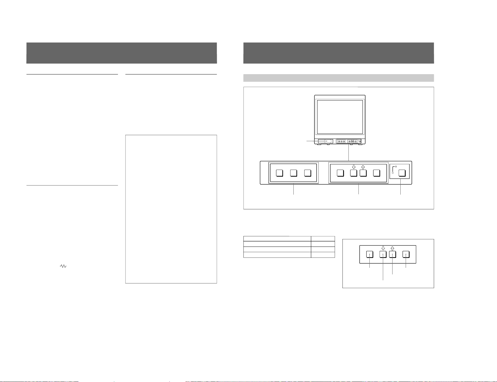
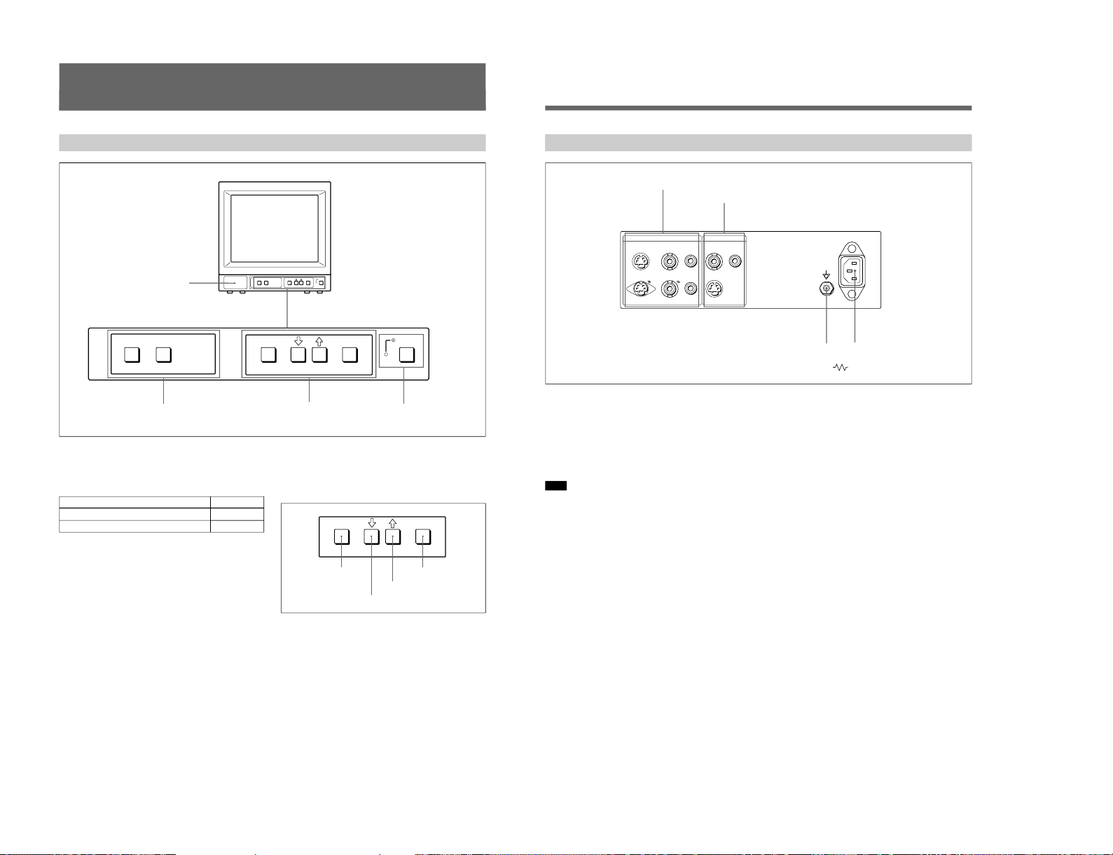
Location and Function of Parts and Controls
Front
1
Speaker
2
LINE A/LINE B/RGB buttons
3
MENU buttons
4
UPOWER
switch and
indicator
1 Speaker
2 LINE A/LINE B/RGB (input select) buttons
Press to select the program to be monitored.
Input signal
Signal fed through the LINE A connector
Signal fed through the LINE B connector
Signal fed through the RGB connectors
a)
a) Provided with the PVM-14N6A/14N6E/14N6U/20N6A/
20N6E/20N6U only.
Press
LINE A
LINE B
RGB
a)
3 MENU buttons
Press to make the menu appear.
For detailed information on MENU buttons, see “Operation
through On-Screen Menus” on page 9.
4 UPOWER switch and indicator
Press to turn the monitor on. The indicator lights in
green.
To turn the power off, press this again.
ENTER
MENU/
EXIT
MENU/EXIT button
. button
> button
ENTER button
1-3
1-4
6
1 LINE A connectors
Input connectors for the composite video, Y/C separate
video and audio signals and their loop-through output
connectors.
To monitor the input signal fed through these
connectors, press the LINE A button on the front
panel.
Note
The Y/C IN connector has priority over the VIDEO IN
connector.
When connecting the cable to the Y/C IN connector,
the Y/C IN connector is automatically selected and the
VIDEO IN connector is disconnected even if the cable
is connected.
Y/C IN connector (4-pin mini-DIN)
Connect to the Y/C separate output connector of a
video camera, VCR or other video equipment.
Y/C OUT connector (4-pin mini-DIN)
Loop-through output of the Y/C IN connector.
Connect to the Y/C separate input connector of a VCR
or another monitor.
When the cable is connected to this connector, the 75ohm termination of the input is automatically released,
and the signal input to the Y/C IN connector is output
from this connector.
VIDEO IN connector (BNC-type)
Connect to the video output connector of video
equipment, such as a VCR or a color video camera.
For a loop-through connection, connect to the video
output connector of another monitor.
VIDEO OUT connector (BNC-type)
Loop-through output connector of the VIDEO IN
connector. Connect to the video input connector for a
VCR or another monitor.
When the cable is connected to this connector, the 75ohm termination of the input is automatically released,
and the signal input to the VIDEO IN connector is
output from this connector.
AUDIO IN connector (phono jack)
Connect to the audio output connector of a VCR or
other equipment. For a loop-through connection,
connect to the audio output of another monitor.
AUDIO OUT connector (phono jack)
Loop-through output of the AUDIO IN connector.
Connect to the audio input connector of a VCR or
another monitor.
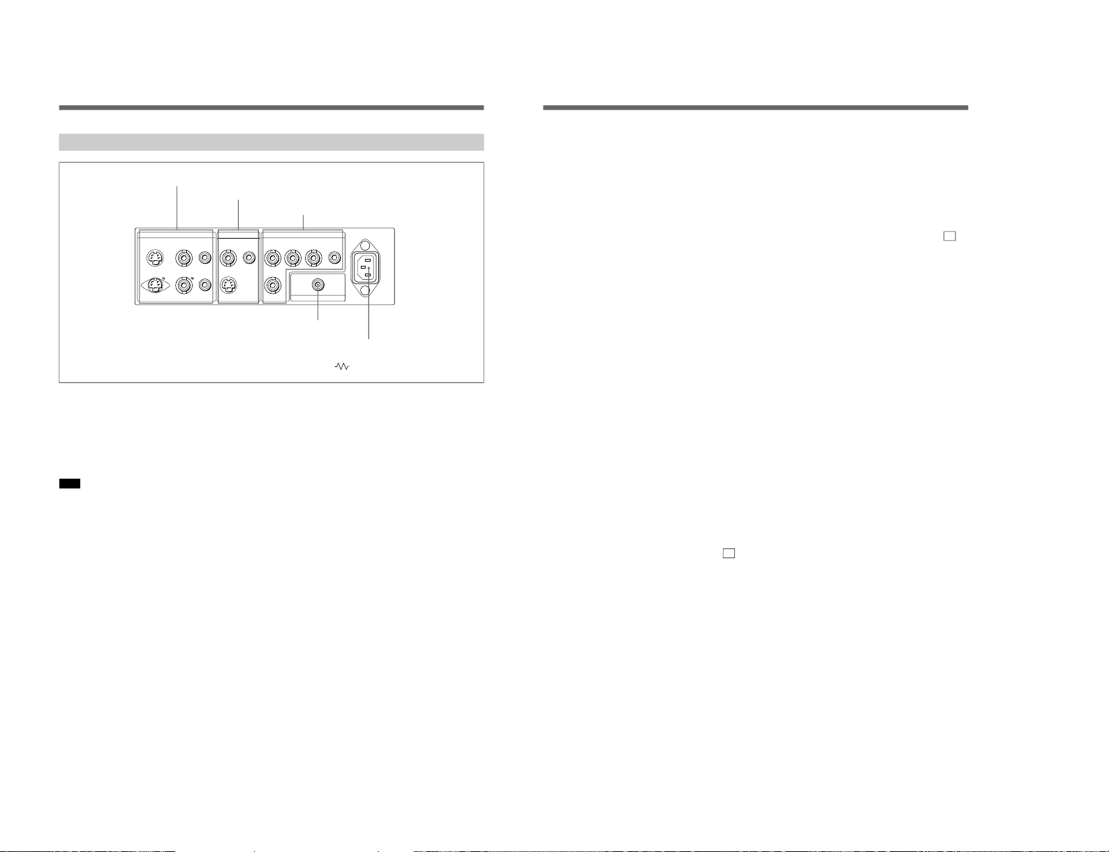
Location and Function of Parts and Controls
Rear Panel
(The mark indicates automatic termination.)
LINE BLINE A RGB ~ AC IN
Y/CINVIDEOINAUDIO
IN
OUT OUT OUT
VIDEOINAUDIO
IN
Y/C
IN
R G B AUDIO
EXT
SYNC
REMOTE
4
REMOTE connector
5
⁄AC IN connector
1
LINE A connectors
3
RGB connectors
2
LINE B connectors
7
2 LINE B connectors
Input connectors for the composite video, Y/C separate
video and audio signals.
To monitor the input signal fed through these
connectors, press the LINE B button on the front
panel.
Y/C IN connector (4-pin mini-DIN)
Connect to the Y/C separate output connector of a
video camera, VCR or other video equipment.
VIDEO IN connector (BNC-type)
Connect to the video output connector of video
equipment, such as a VCR or a color video camera.
For a loop-through connection, connect to the video
output connector of another monitor.
AUDIO IN connector (phono jack)
Connect to the audio output connector of a VCR or
other equipment. For a loop-through connection,
connect to the audio output of another monitor.
3 RGB connectors
(provided with the PVM-14N6A/14N6E/14N6U /
20N6A/20N6E/20N6U only)
Analog RGB input connectors for the R/G/B signals,
external sync signals and audio signals.
To monitor the input signal fed through these
connectors, press the RGB button on the front panel.
R/G/B (input) connectors (BNC-type)
Connect to the analog RGB outputs connectors of a
video camera, VCR or other video equipment. The
monitor operates on the external sync signal.
The monitor also can operate on the sync signal from
the G channel by setting RGB SYNC to SYNC ON
GREEN in the menu.
For detailed information on sync signal setting, see “ 3a
RGB SYNC menu ”on page 12 of “Functions of On-Screen
Menus”.
AUDIO IN connector (phono jack)
Connect to the audio output connectors of video
equipment when the analog RGB signal is input.
EXT SYNC (external sync input) connector
(BNC-type)
Connect to the sync signal output of a video camera,
VCR or other video equipment.
When you set RGB SYNC to SYNC ON GREEN in
the menu, the monitor operates on the sync signal from
the G channel so that it is not necessary to use this
connector.
For detailed information on sync signal setting, see “ 3a
RGB SYNC menu ”on page 12 of “Functions of On-Screen
Menus”.
4 REMOTE connector (phono jack)
(provided with the PVM-14N6A/14N6E/14N6U /
20N6A/20N6E/20N6U only)
This connector functions as follows.
Open: When this connector is open, the current input
signal is selected.
Ground: By grounding this connector, the input
signal selected before the current signal is selected.
5 ⁄AC IN (inlet) connector
Connect the supplied AC power cord to this connector
and to a wall outlet.
SIIA Chassis
SIIA Chassis
8
Using On-Screen Menus
You can make various settings and adjustments of the
monitor using the on-screen menus.
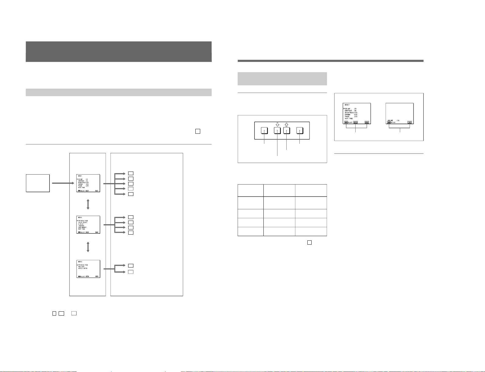
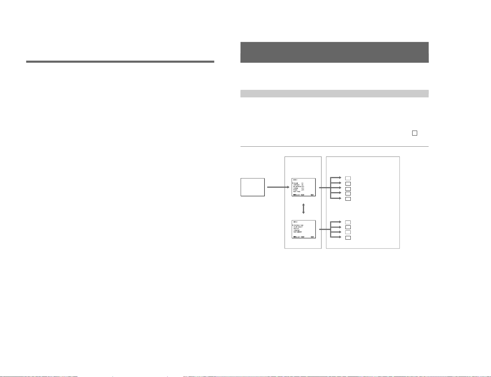
On-Screen Menu Configuration
Regular screen
1 MENU 1
On-screen menu tree-chart
2 MENU 2
3 MENU 3
a)
Item selection menus Adjustment and setting menus
a) These menus ( 3 , 3a and 3b ) are provided with PVM-14N6A/14N6E/14N6U /20N6A/20N6E/20N6U only.
Adjustment and setting menus
You can make desired adjustment or setting on
corresponding menu. The settings and adjustments
remain unchanged until next adjustment even if you
turn off the power.
To reset the settings and adjustments to the factorysettings, select “ FACTORY PRESET” from 2d USER
MEMORY menu.
The on-screen menu is composed of the following two
menu types.
Item selection menu
You can select an adjustment and setting item such as
sound volume, contrast, brightness, color intensity,
color system and menu language by using the >,. and
ENTER buttons.
1a VOLUME menu
1b CONTRAST menu
1c BRIGHTNESS menu
1d CHROMA menu
1e PHASE menu
2a COLOR SELECT menu
2b DISPLAY menu
2c LANGUAGE menu
2d USER MEMORY menu
3a RGB SYNC menu
a)
3b ASPECT RATIO menu
a)
..........................................................................................................................................................................................................
9
ENTER
MENU/
EXIT
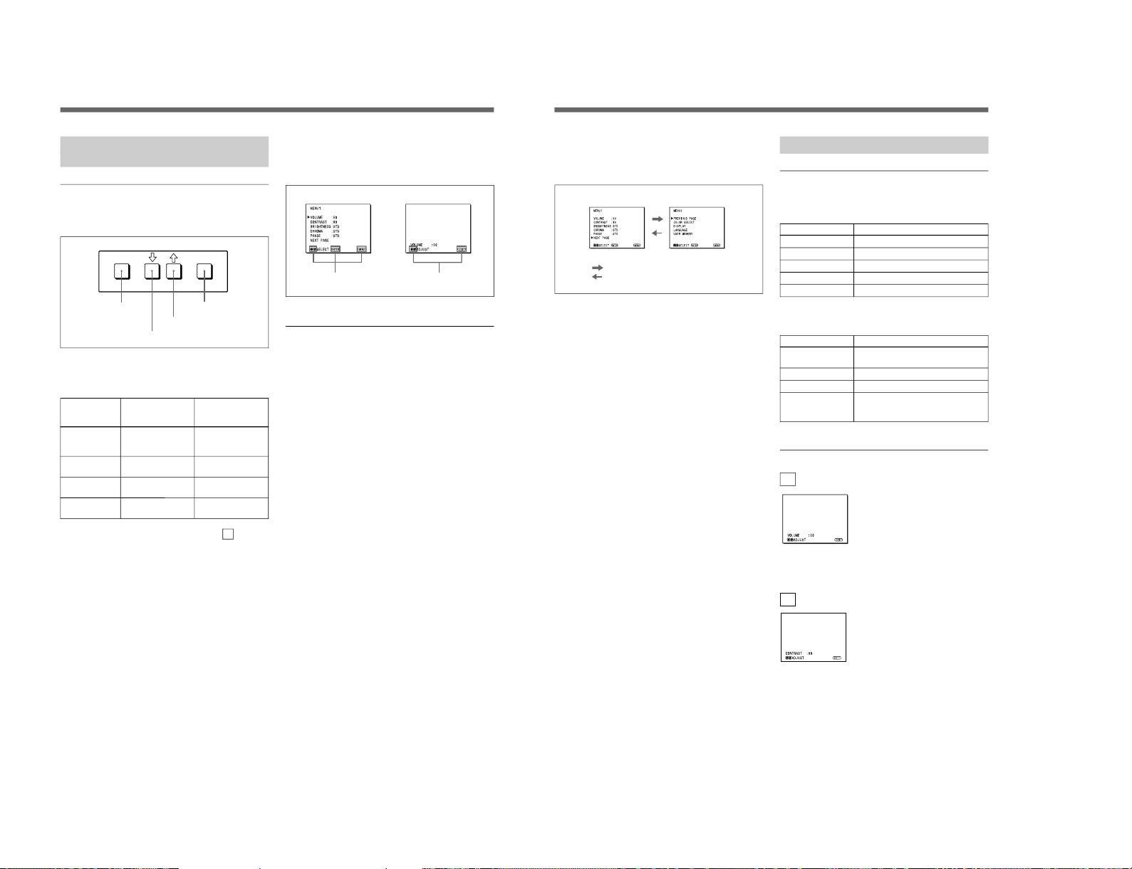
Operation through On-Screen
Menus
Menu operation buttons
There are four menu operation buttons on the front
panel of the monitor.
Button functions depend on the displayed menu. The
following table shows the button functions on the item
selection menus and adjustment and setting menus.
Button
1 MENU/EXIT
2 .
3 >
4 ENTER
a) You can use the ENTER button only on the 2d USER
MEMORY menu of the adjustment and setting menus.
1) 3 MENU 3 is provided with PVM-14N6A/14N6E/14N6U/20N6A/20N6E/20N6U only.
Operating procedures
To display the menu, follow this procedure.
1
Press the MENU/EXIT (1) button.
2 MENU 1 appears.
To select items other than ones not displayed on
MENU 1
Select 2 MENU 2 or 3 MENU 3
1)
.
For details of how to select, see the “To change the item
selection menus” described later.
2
Move the cursor to the desired item by pressing the
. or > (2, 3) button.
3
Press the ENTER (4) button.
The adjustment and setting menu selected in step 2
appears.
For detailed information of menus, see “Functions of OnScreen Menus” on page 10.
Usable buttons depend on the displayed menu. Buttons
that can be used on the menu are displayed at the
bottom line of the screen. You can perform menu
operation using displayed buttons.
Display of the usable menu operation buttons
Menu
Usable buttons
Usable buttons
Function on the
item selection
menus
To return to the
regular screen.
To move the cursor
downward.
To move the cursor
upward.
To decide a
selected item.
Function on the
adjustment and
setting menus
To return to the
item selection
menu.
To decrease value/
select item.
To increase value/
select item.
To decide a
selected item
a)
.
1 MENU/EXIT button
3 > button
2 . button
4 ENTER button
..........................................................................................................................................................................................................
1-5
1-6
10
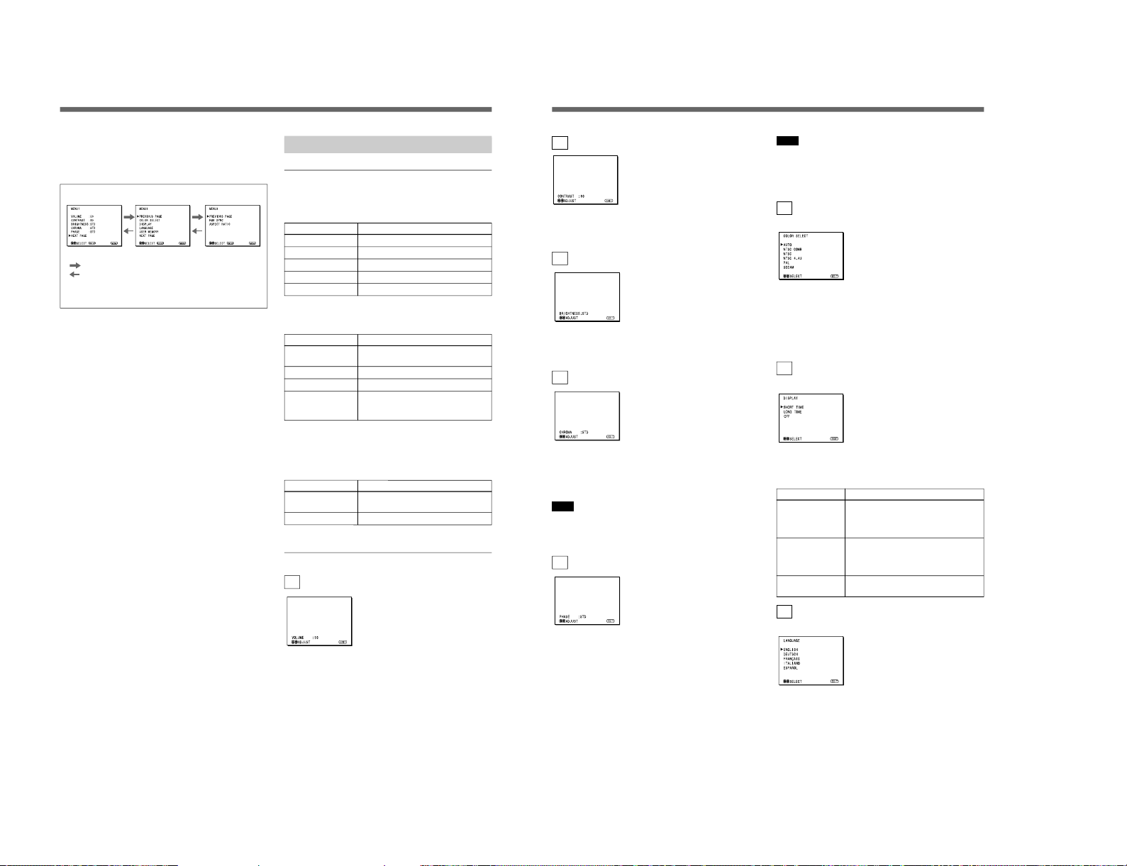
To change the item selection menus
Select NEXT PAGE on the menu to display next item
selection menu and PREVIOUS PAGE on the menu to
display the previous item selection menu.
How to change the item selection menu
To return to the item selection menu from the
adjustment and setting menus
Press the MENU/EXIT (1) button on the currently
displayed adjustment and setting menu.
To close the menu (to return to the regular
screen)
Press the MENU/EXIT (1) button when the item
selection menu is displayed. The on-screen menu
disappears and the regular screen appears.
Using the Last Control Function
If you press the > or . button when the menu is not
displayed, one of the following menu items that you
adjusted last time is displayed.
•VOLUME
•CONTRAST
•BRIGHTNESS
•CHROMA
•PHASE
Then you can adjust the item immediately.
Functions of On-Screen Menus
Item selection menus
1 MENU 1
MENU 1 menu has the following selection items.
Item
VOLUME
CONTRAST
BRIGHTNESS
CHROMA
PHASE
2 MENU 2
MENU 2 menu has the following selection items.
Item
COLOR SELECT
DISPLAY
LANGUAGE
USER MEMORY
3 MENU 3
(for PVM-14N6A/14N6E/14N6U/20N6A/
20N6E/20N6U only)
MENU 3 menu has the following selection items.
Item
RGB SYNC
ASPECT RATIO
Adjustment and setting menu
1a VOLUME menu (Factory setting: 50)
Adjust the speaker volume.
The volume increases by pressing the > button.
The volume decreases by pressing . button.
Using On-Screen Menus
:
:
MENU 1 MENU 2 MENU 3
a)
When selecting NEXT PAGE
When selecting PREVIOUS PAGE
a) MENU 3 is provided with PVM-14N6A/14N6E/14N6U/
20N6A/20N6E/20N6U only.
Functions
To obtain the desired volume
To adjust the contrast
To adjust the brightness
To adjust the color intensity
To adjust the phase
Function
To select the color system of the
input signal
To select period of display
To select the menu language
To store and recall the values and
settings adjusted by a user, and recall
the factory-settings
Function
To select the sync signal when the
RGB signals are input
To select the aspect ratio
11
1b CONTRAST menu (Factory setting: 80)
Adjust the contrast of the screen.
The contrast becomes higher by pressing the > button.
The contrast becomes lower by pressing . button.
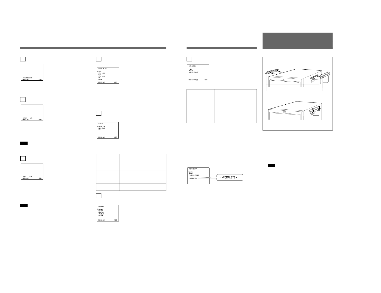
1c BRIGHTNESS menu (Factory setting: STD)
Adjust the brightness of the screen.
The screen becomes brighter by pressing the > button.
The screen becomes darker by pressing . button.
1d CHROMA menu (Factory setting: STD)
Adjust the color intensity of the video signal.
The color intensity strengthens by pressing the >
button.
The color intensity weakens by pressing . button.
Note
The color intensity of an composite video signal or a
Y/C separate signal can be corrected on this menu.
That of the RGB signals cannot be corrected.
1e PHASE menu (Factory setting: STD)
Adjust the phase of the video signals.
The skin tone becomes greenish by pressing the >
button.
The skin tone becomes purplish by pressing the .
button.
Note
The phase of an NTSC composite video signal or a
Y/C separate signal can be corrected on this menu. The
PAL composite video signal or a Y/C separate signal
and RGB signals cannot be corrected.
2a COLOR SELECT menu
(Factory setting: AUTO)
Select the color system of the input signal.
AUTO: Input color systems are automatically
selected.
When you input NTSC signal, comb filter will
activate. To monitor NTSC signal with trap filter,
select NTSC in this menu.
2b DISPLAY menu
(Factory setting: SHORT TIME)
Select the period of displaying the color system of the
current input signals.
The items have the following functions.
Item
SHORT TIME
LONG TIME
OFF
2c LANGUAGE menu
(Factory setting: ENGLISH)
Select the menu language among the five languages,
English, German, French, Italian and Spanish.
Function
To display the kind of color system
being used for several seconds on the
screen each time you change the
signal input.
To display the kind of color system
being used for approximately five
minutes on the screen each time you
change the signal input.
Not to display the kind of the color
system.
SIIA Chassis
SIIA Chassis
12
The following menus are provided with the PVM14N6A/14N6E/14N6U /20N6A/20N6E/20N6U only.
3a RGB SYNC menu
(Factory setting: EXT SYNC)
Select the sync signal when the RGB signals are input.
The items have the following functions.
Item
EXT SYNC
SYNC ON GREEN
3b ASPECT RATIO menu
(Factory setting: 4:3)
Select the aspect ratio of the screen.
2d USER MEMORY menu
The items have the following functions.
Item
STORE
RECALL
FACTORY PRESET
a) The current settings and adjusted values are reset to the
factory settings. The values and settings adjusted and
stored in the internal memory by using the STORE
menu, however, are not changed. To reset internally
stored adjusted values and settings to the factory setting,
select FACTORY PRESET, first, then select STORE.
When you press the ENTER (4) button, the following
message is displayed for about two seconds. The
currently selected item becomes active when pressing
the ENTER (4) button.
Using On-Screen Menus
Function
To store all adjustments and
settings currently set on each
menu into the internal memory.
To recall all adjustments and
settings currently stored in the
internal memory.
To reset the adjustments and
settings currently set on each
menu to the factory settings.
a)
Function
To operate the monitor on an
external sync signal fed through the
RGB SYNC connector.
To operate the monitor on the sync
signal from the G channel.
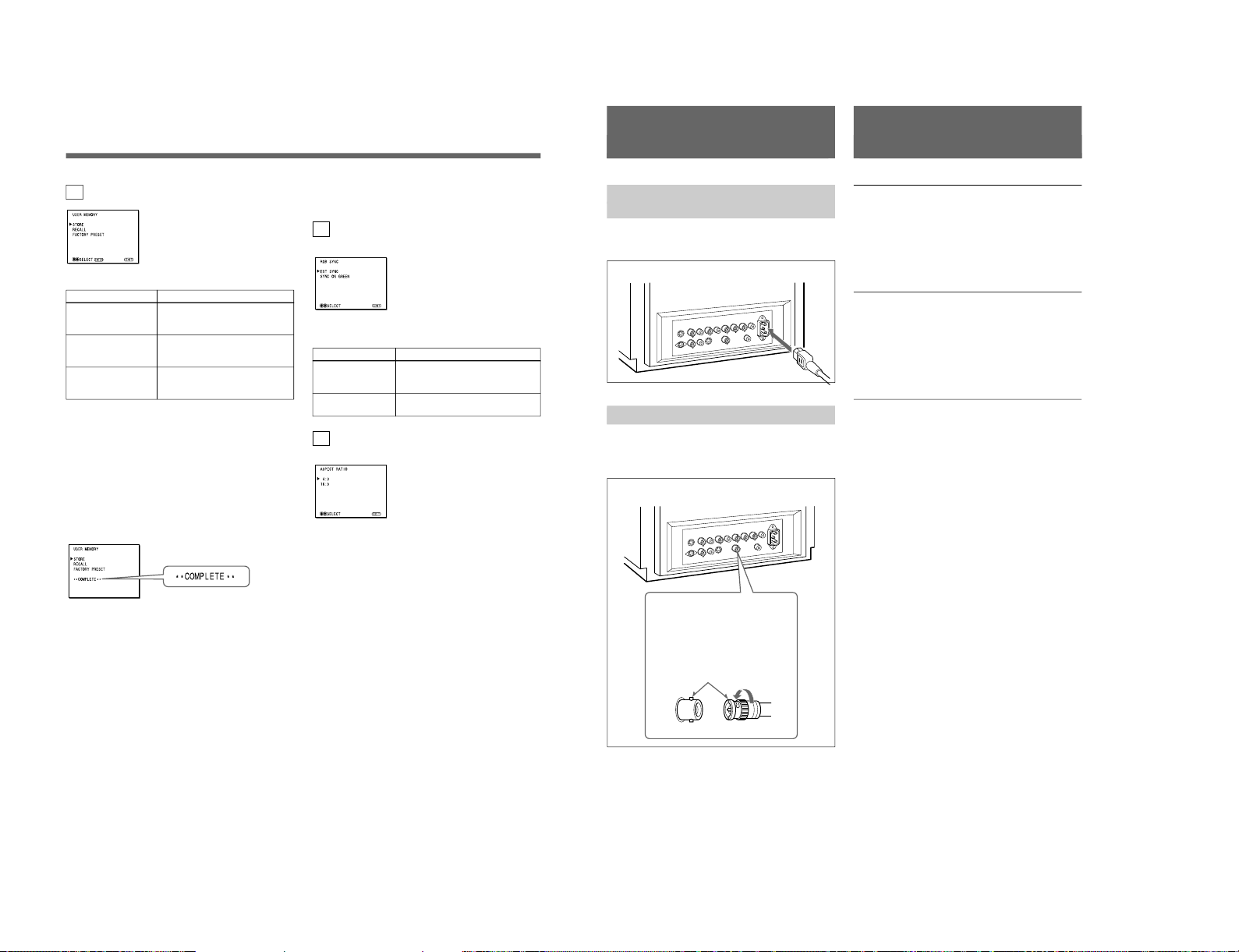
13
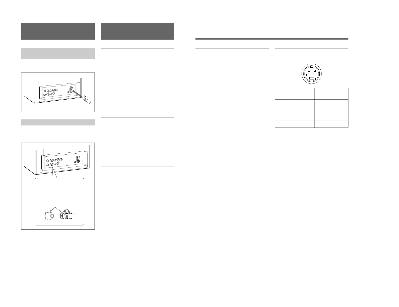
Connections
How to Connect the AC Power
Cord
Connect the AC power cord (supplied) to the ⁄AC IN
connector and to a wall outlet.
How to Connect a Cable to a BNC Connector
Connect the coaxial cable with the BNC connectors to
the BNC connectors on the rear panel as illustrated
below.
Video signal
Color system NTSC, PAL, SECAM, NTSC
4.43
Resolution 500 TV lines
Frequency response
LINE 6 MHz±3dB (Y signal)
RGB 6 MHz±3dB
Picture performance
Normal scan 7 % over scan of CRT effective
screen area
H. linearity Less than 8.0 % (typical)
V. linearity Less than 7.0 % (typical)
Color temperature D65
Inputs
LINE A/B
Y/C IN 4-pin mini-DIN(×2)
See the pin assignment on the next page.
VIDEO IN BNC connector (×2), 1Vp-p +3 dB,
–6 dB, sync negative
AUDIO IN Phono jack (×2), –5 dBu
a)
, more
than 47 kilo-ohms
RGB (PVM-14N6A/14N6E/14N6U/20N6A/20N6E/
20N6U only)
R/G/B BNC connector (×3)
0.7 Vp-p +3 dB, –6 dB
Sync on green: 0.3 Vp-p, negative
AUDIO IN Phono jack (×1), –5 dBu
a)
, more
than 47 kilo-ohms
EXT SYNC BNC connector (×1)
4 Vp-p +3 dB, –6 dB, sync
negative
REMOTE (PVM-14N6A/14N6E/14N6U/20N6A/
20N6E/20N6U only)
Phono jack (×1)
Open: currently selected input
signal
Low state (GND): input signal
selected prior to the current input
signal
a) 0 dBu = 0.775 Vr.m.s.
Insert the connector into the BNC
connector on the rear panel,
matching the slit and pin, and turn
the cable BNC connector clockwise
to secure the BNC connector of a
coaxial cable.
Specifications
1-7
1-8
14
Specifications
Outputs
LINE A
Y/C OUT 4-pin mini-DIN (×1) loop-through,
Automatic 75 ohms termination
VIDEO OUT
BNC connector (×1) loop-through,
Automatic 75 ohms termination
AUDIO OUT
Phono jack (×1) loop-through
Speaker output Output level: 0.8 W
General
CRT PVM-14N5A/14N5E/14N5U/
14N6A/14N6E/14N6U:
14-inch CRT with P-22 phosphor
Visible picture size 340 mm
(13-inch measured diagonally)
PVM-20N5A/20N5E/20N5U/
20N6A/20N6E/20N6U:
20-inch CRT with P-22 phosphor
Visible picture size 490 mm
(19-inch measured diagonally)
Power consumption
PVM-14N5A/14N5E/14N5U: 80W
PVM-14N6A/14N6E/14N6U: 80W
PVM-20N5U/20N6U: 100W
PVM-20N5A/20N6A/20N5E/
20N6E: 105 W
Power requirements
100 to 240 V AC, 50/60Hz
“For use of PVM-14N5U/14N6U/
20N5U/20N6U”, operate these
monitors on 120 V AC.
Operating conditions
Temperature 0 to +35°C
Humidity 0 to 90% (no condensation)
Transport and Storage conditions
Temperature –10 to +40°C
Humidity 0 to 90%
Dimensions (w/h/d)
PVM-14N5A/14N5E/14N5U/
14N6A/14N6E/14N6U:
346 × 340 × 414 mm
(13
5
⁄8 × 131⁄2 × 163⁄8 inches)
PVM-20N5A/20N5E/20N5U/
20N6A/20N6E/20N6U:
449 × 441 × 502 mm
(17
3
⁄4 × 173⁄8 × 197⁄8 inches)
Mass PVM-14N5A/14N5E/14N5U/
14N6A/14N6E/14N6U:
Approx. 15 kg (33 lb 1 oz)
PVM-20N5A/20N5E/20N5U/
20N6A/20N6E/20N6U:
Approx. 28 kg (61 lb 12 oz)
Accesory supplied AC power cord (1)
Operating Instructions (1)
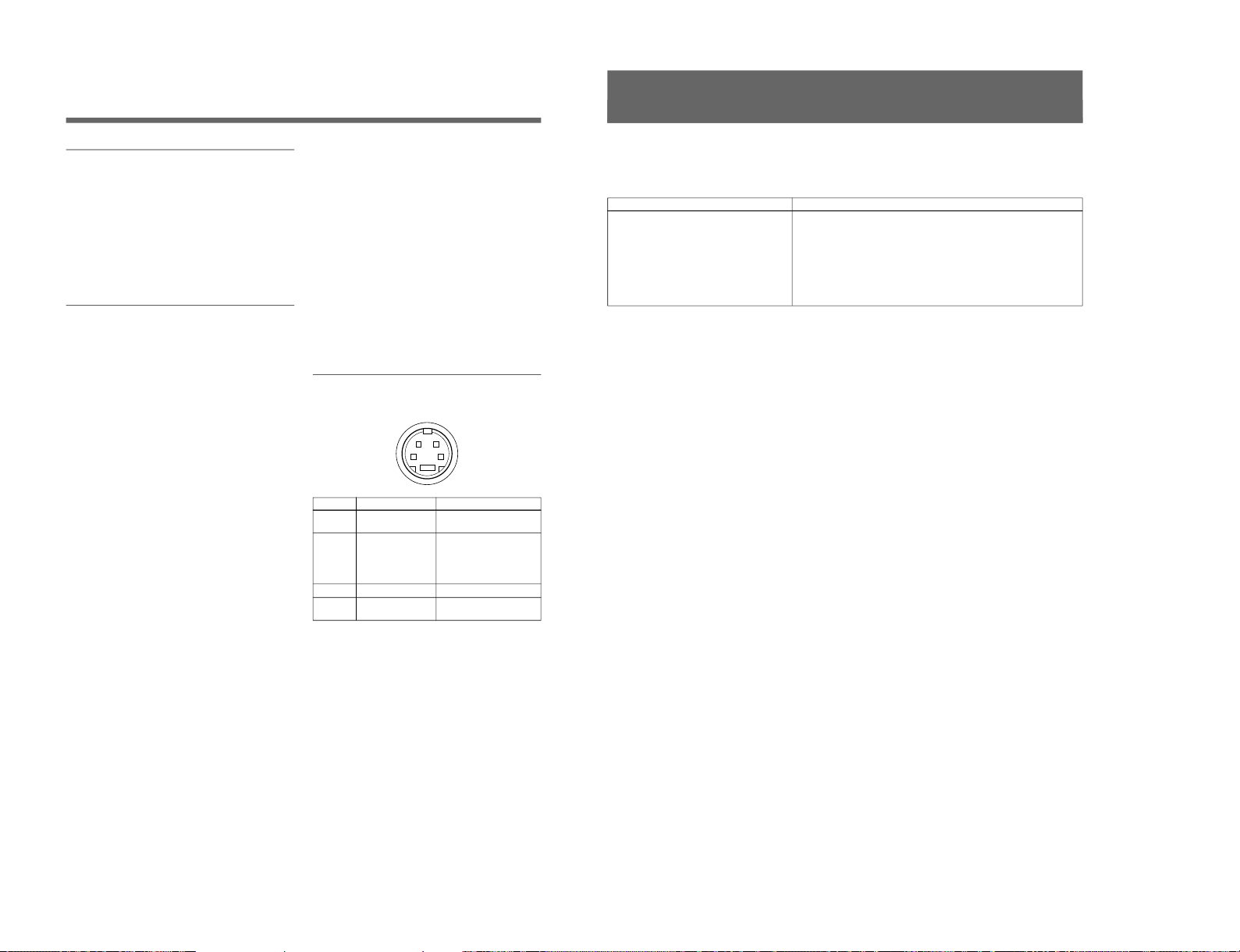
Pin assignment
Y/C IN connector (4-pin mini-DIN)
21
34
*
Pin No.
1
2
3
4
Design and specifications are subject to change
without notice.
Signal
Y-input
CHROMA
subcarrier-input
GND for Y-input
GND for CHROMA-
input
Description
1 Vp-p, sync negative, 75
ohms
0.286 Vp-p (NTSC), 300m
Vp-p (PAL), burst
Delay time between Y and
C: within 0 ± 100 nsec.,
75 ohms
GND
GND
15
This section may help you isolate the problem. Should
the problem persist, unplug the unit and contact your
Sony dealer or local authorized Sony service facility.
Troubleshooting
Symptom
If colors are not accurately reproduced
Possible causes and remedies
The monitor input signal is deviated from the color system specifications (i.e.
signals from VCRs).
Proceed as follows to correct this phenomenon.
1
Confirm the color system of the input signal.
2
Select the same color system as that of the input signal on the COLOR
SELECT menu.
If the problem remains unsolved after corresponding color system is
selected, briefly turn OFF the power, then turn ON the monitor again.
SIIA Chassis
SIIA Chassis
Trinitron
®
Color Video Monitor
3-864-165-11(2)
PVM-14N5MDE
Instructions for Use
Page 2
Mode d’emploi
Page 18
Gebrauchsanweisung
Seite 34
Instrucciones de uso
Página 50
Istruzioni per l’uso
Pagina 66
######
82
EN
F
D
1998 by Sony Corporation
E
I
C
8
1-2. PVM-14N5MDE
1-9
1-10
2
English
Owner’s Recor d
The model and serial numbers are located at the rear.
Record these numbers in the spaces provided below.
Refer to these numbers whenever you call upon your
Sony dealer regarding this product.
Model No.
Serial No.
WARNING
To prevent fire or shock hazard, do not
expose the unit to rain or moisture.
Dangerously high voltage are present
inside the unit.
Do not open the cabinet. Refer servicing
to qualified personnel only.
In the event of a malfunction or when maintenance is
necessary, consult an authorized Sony dealer.
Power Switch
The power switch is a functional switch only. To isolate
the set from the mains supply remove the mains plug
from the wall socket.
For the customers in the U.S.A.
This equipment has been tested and found to comply with
the limits for a Class A digital device, pursuant to Part 15 of
the FCC Rules. These limits are designed to provide
reasonable protection against harmful interference when the
equipment is operated in a commercial environment.
This equipment generates, uses, and can radiate radio
frequency energy and, if not installed and used in
accordance with the instruction manual, may cause harmful
interference to radio communications. Operation of this
equipment in a residential area is likely to cause harmful
interference in which case the user will be required to correct
the interference at his own expense.
You are cautioned that any changes or modifications not
expressly approved in this manual could void your authority
to operate this equipment.
For the customers in the United Kingdom
WARNING
THIS APPARATUS MUST BE EARTHED
IMPORTANT
The wires in this mains lead are coloured in accordance with
the following code:
Green-and-yellow: Earth
Blue: Neutral
Brown: Live
As the colours of the wires in the mains lead of this
apparatus may not correspond with the coloured markings
identifying the terminals in your plug proceed as follows:
The wire which is coloured green-and-yellow must be
connected to the terminal in the plug which is marked by the
letter E or by the safety earth symbol Y or coloured green or
green-and-yellow.
The wire which is coloured blue must be connected to the
terminal which is marked with the letter N or coloured black.
The wire which is coloured brown must be connected to the
terminal which is marked with the letter L or coloured red.
Ensure that your equipment is connected correctly - If you
are in any doubt consult a qualified electrician.
This unit contains substances which can pollute the
environment if disposed carelessly. Please contact our
nearest office or your local environmental office in case of
disposal of this unit.
ATTENTION:
Picture distortion may occur if this monitor is positioned
in close proximity to any equipment emitting
electromagnetic radiation.
3
Table of Contents
Precaution
On safety
•Operate the unit only with a power source as
specified in “Specifications” section.
•The nameplate indicating operating voltage, power
consumption, etc., is located at the rear.
•Should any solid object or liquid fall into the cabinet,
unplug the unit and have it checked by qualified
personnel before operating it any further.
•Do not drop or place heavy objects on the power
cord. If the power cord is damaged, turn off the
power immediately. It is dangerous to use the unit
with a damaged power cord.
•Unplug the unit from the wall outlet if it is not to be
used for several days or more.
•Disconnect the power cord from the AC outlet by
grasping the plug, not by pulling the cord.
•The socket-outlet shall be installed near the
equipment and shall be easily accessible.
On installation
•Allow adequate air circulation to prevent internal heat
build-up.
Do not place the unit on surfaces (rugs, blankets, etc.)
or near materials (curtains, draperies) that may block
the ventilation holes.
•Do not install the unit in a location near heat sources
such as radiators or air ducts, or in a place subject to
direct sunlight, excessive dust, mechanical vibration
or shock.
On cleaning
To keep the unit looking brand-new, periodically clean
it with a mild detergent solution. Never use strong
solvents such as thinner or benzine, or abrasive
cleansers since they will damage the cabinet. As a
safety precaution, unplug the unit before cleaning it.
On repacking
Do not throw away the carton and packing materials.
They make an ideal container to transport the unit.
If you have any questions about this unit, contact your
authorized Sony dealer.
About this manual
Before operating the unit, please read this manual
thoroughly and retain it for future reference.
Attention – when the product is installed in a rack:
•Elevated operating ambient temperature
If installed in a closed or multi-unit rack
assembly, the operating ambient temperature of
the rack environment may be greater than room
ambient.
Therefore, consideration should be given to
installing the equipment in an environment
compatible with the manufacturer’s maximum
rated ambient temperature of 0 to +40 ºC (Tmra).
•Reduced air flow
Installation of the equipment in a rack should be
such that the amount of air flow required for safe
operation of the equipment is not compromised.
•Mechanical loading
Mounting of the equipment in the rack should be
such that a hazardous condition is not achieved
due to uneven mechanical loading.
•Circuit overloading
Consideration should be given to the connection
of the equipment to the supply circuit and the
effect that overloading of circuits might have on
overcurrent protection and supply wiring.
Appropriate consideration of equipment
nameplate ratings should be used when
addressing this concern.
•Reliable earthing
Reliable earthing of rack-mounted equipment
should be maintained. Particular attention should
be given to supply connections other than direct
connections to the branch circuit (e.g., use of
power strips).
Features ............................................................ 5
Location and Function of Parts and Controls 6
Front .................................................................... 6
Rear Panel ........................................................... 7
Using On-Screen Menus.................................. 9
On-Screen Menu Configuration .......................... 9
Operation through On-Screen Menus ............... 10
Functions of On-Screen Menus......................... 11
Attaching the Side Covers ............................ 13
Connections ................................................... 14
How to Connect the AC Power Cord ................ 14
How to Connect a Cable to a BNC Connector.. 14
Specifications................................................. 14
Troubleshooting............................................. 16
SIIA Chassis
SIIA Chassis
4
Be sure to connect the AC power cord to a
grounded outlet.
Important safeguards/notices for use in the
medical environments
1
All the equipments connected to this unit shall be
certified according to Standard IEC601-1, IEC950,
IEC65 or other IEC/ISO Standards applicable to
the equipments.
2
When this unit is used together with other
equipment in the patient area*, the equipment shall
be either powered by an isolation transformer or
connected via an additional protective earth
terminal to system ground unless it is certified
according to Standard IEC601-1 and IEC601-1-1.
* Patient Area
3
The leakage current could increase when
connected to other equipment.
4
The operator should take precautions to avoid
touching the rear panel input and output circuitry
and the patient at the same time.
5
Model PVM-14N5MDE is a video monitor
intended for use in a medical environment to
display video pictures from cameras or other video
system.
R1.5m
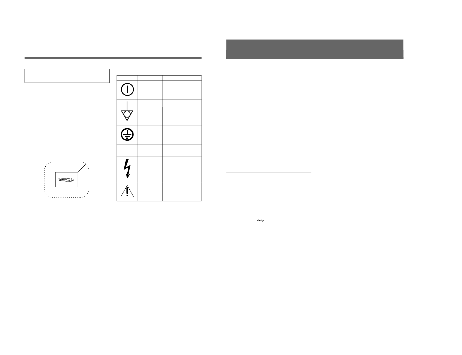
Symbols on the unit
Symbol
Location
Front panel
Rear panel
Inside the unit
Rear panel
Inside the unit
Rear panel
This symbol indicates
Main power switch.
Press to turn the monitor
on or off.
The equipotential terminal
which brings the various
parts of a system to the
same potential.
Protective earth
Alternating current
Presence of uninsulated
“dangerous voltage” within
the product’s enclosure
that may be sufficient to
constitute a risk of electric
shock.
Attention, consult
ACCOMPANYING
DOCUMENTS
⁄
5
Picture
Fine pitch Trinitron
1)
picture tube
The fine pitch Trinitron tube provides a high resolution
picture. Horizontal resolution is more than 500 TV
lines at the center of the picture.
Comb filter
When NTSC video signals are received, a comb filter
activates to make more accurate Y/C separation. This
contributes to less of a decrease in resolution, cross
color and cross luminance phenomena.
Beam current feedback circuit
The built-in beam current feedback circuit assures
stable white balance.
Four color system available
The monitor can display NTSC, PAL, SECAM and
NTSC
4.43
2)
signals. The appropriate color system is
selected automatically.
Input
Y/C input connectors
The video signal, split into the chrominance signal (C)
and the luminance signal (Y), can be input through this
connector, eliminating the interference between the
two signals, which tends to occur in a composite video
signal, ensuring video quality.
Automatic termination
(connector with
mark only)
The input connector is terminated at 75 ohms inside
when no cable is connected to the loop-through output
connector. When a cable is connected to an output
connector, the 75-ohm termination is automatically
released.
Features
Functions
On-screen menus
You can set monitor operation settings by using the
on-screen menus.
EIA standard 19-inch rack mounting
By using an MB-502B mounting bracket (not
supplied), the monitor can be mounted in an EIA
standard 19-inch rack.
For details on mounting, refer to the instruction manuals
supplied with the mounting bracket kit.
Side covers
The monitor can be covered with side covers. The side
covers that protect the ventilation holes from splashes
(of medicines, etc.) as much as possible.
1) Trinitron
“Trinitron” is a registered trademark of Sony Corporation.
2) NTSC
4.43
The NTSC
4.43
system refers to an NTSC color system in which the subcarrier frequency is modified to 4.43MHz. When an
NTSC recorded video program is played back with a Trident (PAL/SECAM/NTSC
4.43
) VTR, the NTSC
4.43
signal is output.
..........................................................................................................................................................................................................
1-11
1-12
6
LINE A LINE B ENTER
MENU/
EXIT
POWER
LINE A LINE B ENTER
MENU/
EXIT
POWER
ENTER
MENU/
EXIT
Location and Function of Parts and Controls
ENTER button
Front
2
LINE A/LINE B buttons
3
MENU buttons
4
UPOWER switch
and indicator
1 Speaker
2 LINE A/LINE B (input select) buttons
Press to select the program to be monitored.
Input signal
Signal fed through the LINE A connector
Signal fed through the LINE B connector
Press
LINE A
LINE B
3 MENU buttons
Press to make the menu appear.
For detailed information on MENU buttons, see “Operation
through On-Screen Menus” on page 10.
4 UPOWER switch and indicator
Press to turn the monitor on. The indicator lights in
green.
To turn the power off, press this again.
MENU/EXIT button
. button
> button
1
Speaker
7
1 LINE A connectors
Input connectors for the composite video, Y/C separate
video and audio signals and their loop-through output
connectors.
To monitor the input signal fed through these
connectors, press the LINE A button on the front
panel.
Note
The Y/C IN connector has priority over the VIDEO IN
connector.
When connecting the cable to the Y/C IN connector,
the Y/C IN connector is automatically selected and the
VIDEO IN connector is disconnected even if the cable
is connected.
Y/C IN connector (4-pin mini-DIN)
Connect to the Y/C separate output connector of a
video camera, VCR or other video equipment.
Y/C OUT connector (4-pin mini-DIN)
Loop-through output of the Y/C IN connector.
Connect to the Y/C separate input connector of a VCR
or another monitor.
When the cable is connected to this connector, the 75ohm termination of the input is automatically released,
and the signal input to the Y/C IN connector is output
from this connector.
VIDEO IN connector (BNC-type)
Connect to the video output connector of video
equipment, such as a VCR or a color video camera.
For a loop-through connection, connect to the video
output connector of another monitor.
VIDEO OUT connector (BNC-type)
Loop-through output connector of the VIDEO IN
connector. Connect to the video input connector for a
VCR or another monitor.
When the cable is connected to this connector, the 75ohm termination of the input is automatically released,
and the signal input to the VIDEO IN connector is
output from this connector.
AUDIO IN connector (phono jack)
Connect to the audio output connector of a VCR or
other equipment. For a loop-through connection,
connect to the audio output of another monitor.
AUDIO OUT connector (phono jack)
Loop-through output of the AUDIO IN connector.
Connect to the audio input connector of a VCR or
another monitor.
Rear Panel
LINE BLINE A ~ AC IN
Y/CINVIDEOINAUDIO
IN
OUT OUT OUT
VIDEOINAUDIO
IN
Y/C
IN
(The mark indicates automatic termination.)
1
LINE A connectors
2
LINE B connectors
4
⁄AC IN connector
3
Ground terminal
SIIA Chassis
SIIA Chassis
8
2 LINE B connectors
Input connectors for the composite video, Y/C separate
video and audio signals.
To monitor the input signal fed through these
connectors, press the LINE B button on the front
panel.
Y/C IN connector (4-pin mini-DIN)
Connect to the Y/C separate output connector of a
video camera, VCR or other video equipment.
VIDEO IN connector (BNC-type)
Connect to the video output connector of video
equipment, such as a VCR or a color video camera.
For a loop-through connection, connect to the video
output connector of another monitor.
AUDIO IN connector (phono jack)
Connect to the audio output connector of a VCR or
other equipment. For a loop-through connection,
connect to the audio output of another monitor.
3 Ground (1) terminal
Connect a GND cable.
4 ⁄AC IN (inlet) connector
Connect the supplied AC power cord to this connector
and to a wall outlet.
Location and Function of Parts and Controls
9
Using On-Screen Menus
You can make various settings and adjustments of the
monitor using the on-screen menus.
Regular screen
1 MENU 1
1a VOLUME menu
1b CONTRAST menu
1c BRIGHTNESS menu
1d CHROMA menu
1e PHASE menu
2a COLOR SELECT menu
2c LANGUAGE menu
2b DISPLAY menu
On-screen menu tree-chart
2 MENU 2
Item selection menus Adjustment and setting menus
2d USER MEMORY menu
Adjustment and setting menus
You can make desired adjustment or setting on
corresponding menu. The settings and adjustments
remain unchanged until next adjustment even if you
turn off the power.
To reset the settings and adjustments to the factorysettings, select “ FACTORY PRESET” from 2d USER
MEMORY menu.
The on-screen menu is composed of the following two
menu types.
Item selection menu
You can select an adjustment and setting item such as
sound volume, contrast, brightness, color intensity,
color system and menu language by using the >,. and
ENTER buttons.
On-Screen Menu Configuration
1-13
1-14
10
ENTER
MENU/
EXIT
Operation through On-Screen
Menus
Menu operation buttons
There are four menu operation buttons on the front
panel of the monitor.
Button functions depend on the displayed menu. The
following table shows the button functions on the item
selection menus and adjustment and setting menus.
Button
1 MENU/EXIT
2 .
3 >
4 ENTER
a) You can use the ENTER button only on the 2d USER
MEMORY menu of the adjustment and setting menus.
1 MENU/EXIT button
3 > button
2 . button
4 ENTER button
Function on the
item selection
menus
To return to the
regular screen.
To move the cursor
downward.
To move the cursor
upward.
To decide a
selected item.
Function on the
adjustment and
setting menus
To return to the
item selection
menu.
To decrease value/
select item.
To increase value/
select item.
To decide a
selected item
a)
.
Operating procedures
To display the menu, follow this procedure.
1
Press the MENU/EXIT (1) button.
1 MENU 1 appears.
To select items other than ones not displayed on
MENU 1
Select 2 MENU 2.
For details of how to select, see the “To change the item
selection menus” described later.
2
Move the cursor to the desired item by pressing the
. or > (2, 3) button.
3
Press the ENTER (4) button.
The adjustment and setting menu selected in step 2
appears.
For detailed information of menus, see “Functions of OnScreen Menus” on page 11.
Usable buttons depend on the displayed menu. Buttons
that can be used on the menu are displayed at the
bottom line of the screen. You can perform menu
operation using displayed buttons.
Display of the usable menu operation buttons
Menu
Usable buttons
Usable buttons
Using On-Screen Menus
11
To change the item selection menus
Select NEXT PAGE on the menu to display next item
selection menu and PREVIOUS PAGE on the menu to
display the previous item selection menu.
How to change the item selection menu
To return to the item selection menu from the
adjustment and setting menus
Press the MENU/EXIT (1) button on the currently
displayed adjustment and setting menu.
To close the menu (to return to the regular
screen)
Press the MENU/EXIT (1) button when the item
selection menu is displayed. The on-screen menu
disappears and the regular screen appears.
:
:
MENU 1 MENU 2
When selecting NEXT PAGE
When selecting PREVIOUS PAGE
Functions of On-Screen Menus
Item selection menus
1 MENU 1
MENU 1 menu has the following selection items.
Item
VOLUME
CONTRAST
BRIGHTNESS
CHROMA
PHASE
2 MENU 2
MENU 2 menu has the following selection items.
Item
COLOR SELECT
DISPLAY
LANGUAGE
USER MEMORY
Adjustment and setting menu
1a VOLUME menu (Factory setting: 50)
Adjust the speaker volume.
The volume increases by pressing the > button.
The volume decreases by pressing . button.
1b CONTRAST menu (Factory setting: 80)
Adjust the contrast of the screen.
The contrast becomes higher by pressing the > button.
The contrast becomes lower by pressing . button.
Functions
To obtain the desired volume
To adjust the contrast
To adjust the brightness
To adjust the color intensity
To adjust the phase
Function
To select the color system of the
input signal
To select period of display
To select the menu language
To store and recall the values and
settings adjusted by a user, and recall
the factory-settings
SIIA Chassis
SIIA Chassis
12
Using On-Screen Menus
1c BRIGHTNESS menu (Factory setting: STD)
Adjust the brightness of the screen.
The screen becomes brighter by pressing the > button.
The screen becomes darker by pressing . button.
1d CHROMA menu (Factory setting: STD)
Adjust the color intensity of the video signal.
The color intensity strengthens by pressing the >
button.
The color intensity weakens by pressing . button.
Note
The color intensity of an composite video signal or a
Y/C separate signal can be corrected on this menu.
1e PHASE menu (Factory setting: STD)
Adjust the phase of the video signals.
The skin tone becomes greenish by pressing the >
button.
The skin tone becomes purplish by pressing the .
button.
Note
The phase of an NTSC composite video signal or a
Y/C separate signal can be corrected on this menu. The
PAL composite video signal or a Y/C separate signal
cannot be corrected.
2a COLOR SELECT menu
(Factory setting: AUTO)
Select the color system of the input signal.
AUTO: Input color systems are automatically
selected.
When you input NTSC signal, comb filter will
activate. To monitor NTSC signal with trap filter,
select NTSC in this menu.
2b DISPLAY menu
(Factory setting: SHORT TIME)
Select the period of displaying the color system of the
current input signals.
The items have the following functions.
Item
SHORT TIME
LONG TIME
OFF
2c LANGUAGE menu
(Factory setting: ENGLISH)
Select the menu language among the five languages,
English, German, French, Italian and Spanish.
Function
To display the kind of color system
being used for several seconds on the
screen each time you change the
signal input.
To display the kind of color system
being used for approximately five
minutes on the screen each time you
change the signal input.
Not to display the kind of the color
system.
13
Attaching the Side
Covers
2d USER MEMORY menu
The items have the following functions.
Item
STORE
RECALL
FACTORY PRESET
a) The current settings and adjusted values are reset to the
factory settings. The values and settings adjusted and
stored in the internal memory by using the STORE
menu, however, are not changed. To reset internally
stored adjusted values and settings to the factory setting,
select FACTORY PRESET, first, then select STORE.
When you press the ENTER (4) button, the following
message is displayed for about two seconds. The
currently selected item becomes active when pressing
the ENTER (4) button.
Using the Last Control Function
If you press the > or . button when the menu is not
displayed, one of the following menu items that you
adjusted last time is displayed.
•VOLUME
•CONTRAST
•BRIGHTNESS
•CHROMA
•PHASE
Then you can adjust the item immediately.
Function
To store all adjustments and
settings currently set on each
menu into the internal memory.
To recall all adjustments and
settings currently stored in the
internal memory.
To reset the adjustments and
settings currently set on each
menu to the factory settings.
a)
In order to protect the ventilation holes from splashes
from medicines, etc., attach the supplied side covers as
illustrated.
1
Hook the tabs on the upper edge into the
ventilation holes, making sure that the arrows on
the cover are facing down.
Note
Attach the side covers on all ventilation holes.
2
Push up the tabs on the bottom edge and fit the
cover into the lowest ventilation holes.
Attach covers on both left and right vents.
2
Side covers
1
Tabs on the upper edge
Arrows
Tabs on the
bottom edge
1-15
1-16
14
Connections
How to Connect the AC Power
Cord
Connect the AC power cord (supplied) to the ⁄AC IN
connector and to a wall outlet.
How to Connect a Cable to a BNC Connector
Connect the coaxial cable with the BNC connectors to
the BNC connectors on the rear panel as illustrated
below.
Insert the connector into the BNC
connector on the rear panel,
matching the slit and pin, and turn
the cable BNC connector clockwise
to secure the BNC connector of a
coaxial cable.
Video signal
Color system NTSC, PAL, SECAM, NTSC
4.43
Horizontal Resolution
500 TV lines
Frequency response
LINE 6 MHz±3dB (Y signal)
Picture performance
Normal scan 7 % over scan of CRT effective
screen area
H. linearity Less than 8.0 % (typical)
V. linearity Less than 7.0 % (typical)
Color temperature D65
Inputs
LINE A/B
Y/C IN 4-pin mini-DIN(×2)
See the pin assignment on the next page.
VIDEO IN BNC connector (×2), 1Vp-p +3 dB,
–6 dB, sync negative
AUDIO IN Phono jack (×2), –5 dBu
a)
, more
than 47 kilo-ohms
a) 0 dBu = 0.775 Vr.m.s.
Outputs
LINE A
Y/C OUT 4-pin mini-DIN (×1) loop-through,
Automatic 75 ohms termination
VIDEO OUT
BNC connector (×1) loop-through,
Automatic 75 ohms termination
AUDIO OUT
Phono jack (×1) loop-through
Speaker output Output level: 0.8 W
Specifications
15
General
Classification of equipment
– Type of protection against electric shock: Class I
equipment
* Standard evaluated to:
EN 60 601-1, EN60 601-1-2
CSA C22.2 No.601.1
UL 2601-1
– Degree of protection against harmful ingress of
water: Ordinary equipment
– Degree of safety of application in the presence of a
flammable anaesthetic mixture:
Not protected equipment
– Mode of operation:
Continuous operation
– Information concerning type and frequency of
technical maintenance:
Not need maintenance equipment
– Main power switch:
Functional switch
CRT 14-inch CRT with P-22
phosphor
Visible picture size 332 mm
(13-inch measured diagonally)
Power consumption
80W
Power requirements
100 to 240 V AC, 50/60 Hz
1.2 - 0.6 A
Operating conditions
Temperature 0 to +40°C
Humidity 30 to 85% (no condensation)
Pressure 700 to 1060 hPa
Transport and Storage conditions
Temperature –10 to +40°C
Humidity 0 to 90%
Pressure 700 to 1060 hPa
Dimensions (w/h/d)
346 × 340 × 414 mm
(13
5
⁄8 × 13
1
⁄2 × 163⁄8 inches)
Mass Approx. 15 kg (33 lb 1 oz)
Accesory supplied
AC power cord (1)
Side covers (2)
Instructions for Use (1)
Pin assignment
Y/C IN connector (4-pin mini-DIN)
21
34
*
Pin No.
1
2
3
4
Design and specifications are subject to change
without notice.
Signal
Y-input
CHROMA
subcarrier-input
GND for Y-input
GND for CHROMA-
input
Description
1 Vp-p, sync negative, 75
ohms
0.286 Vp-p (NTSC), 300m
Vp-p (PAL), burst
Delay time between Y and
C: within 0 ± 100 nsec.,
75 ohms
GND
GND
SIIA Chassis

SIIA Chassis
16
This section may help you isolate the problem. Should
the problem persist, unplug the unit and contact your
Sony dealer or local authorized Sony service facility.
Troubleshooting
Symptom
If colors are not accurately reproduced
Possible causes and remedies
The monitor input signal is deviated from the color system specifications (i.e.
signals from VCRs).
Proceed as follows to correct this phenomenon.
1
Confirm the color system of the input signal.
2
Select the same color system as that of the input signal on the COLOR
SELECT menu.
If the problem remains unsolved after corresponding color system is
selected, briefly turn OFF the power, then turn ON the monitor again.
1-17
1-18
Trinitron
®
Color Video Monitor
3-864-152-11(2)
SSM-14N5E/14N5U/14N5A
SSM-20N5E/20N5U/20N5A
Operating Instructions
Page 2
Mode d’emploi
Page 14
Bedienungsanleitung
Seite 26
Manual de instrucciones
Página 38
Istruzioni per l’uso
Pagina 50
######
62
EN
F
D
1998 by Sony Corporation
E
I
C
1-3. SSM-14N5 (A/E/U), SSM-20N5 (A/E/U)
SIIA Chassis

SIIA Chassis
2
English
Owner’s Record
The model and serial numbers are located at the rear.
Record these numbers in the spaces provided below.
Refer to these numbers whenever you call upon your
Sony dealer regarding this product.
Model No.
Serial No.
WARNING
To prevent fire or shock hazard, do not
expose the unit to rain or moisture.
Dangerously high voltage are present
inside the unit.
Do not open the cabinet. Refer servicing
to qualified personnel only.
In the event of a malfunction or when maintenance is
necessary, consult an authorized Sony dealer.
For the customers in the U.S.A.
This equipment has been tested and found to comply with
the limits for a Class A digital device, pursuant to Part 15 of
the FCC Rules. These limits are designed to provide
reasonable protection against harmful interference when the
equipment is operated in a commercial environment.
This equipment generates, uses, and can radiate radio
frequency energy and, if not installed and used in
accordance with the instruction manual, may cause harmful
interference to radio communications. Operation of this
equipment in a residential area is likely to cause harmful
interference in which case the user will be required to correct
the interference at his own expense.
You are cautioned that any changes or modifications not
expressly approved in this manual could void your authority
to operate this equipment.
For the customers in the United Kingdom
WARNING
THIS APPARATUS MUST BE EARTHED
IMPORTANT
The wires in this mains lead are coloured in accordance with
the following code:
Green-and-yellow: Earth
Blue: Neutral
Brown: Live
As the colours of the wires in the mains lead of this
apparatus may not correspond with the coloured markings
identifying the terminals in your plug proceed as follows:
The wire which is coloured green-and-yellow must be
connected to the terminal in the plug which is marked by the
letter E or by the safety earth symbol Y or coloured green or
green-and-yellow.
The wire which is coloured blue must be connected to the
terminal which is marked with the letter N or coloured black.
The wire which is coloured brown must be connected to the
terminal which is marked with the letter L or coloured red.
Ensure that your equipment is connected correctly - If you
are in any doubt consult a qualified electrician.
ATTENTION:
Picture distortion may occur if this monitor is positioned
in close proximity to any equipment emitting
electromagnetic radiation.
3
On safety
•Operate the unit only with a power source as
specified in “Specifications” section.
•The nameplate indicating operating voltage, power
consumption, etc., is located on the rear.
•Should any solid object or liquid fall into the cabinet,
unplug the unit and have it checked by qualified
personnel before operating it any further.
•Do not drop or place heavy objects on the power
cord. If the power cord is damaged, turn off the
power immediately. It is dangerous to use the unit
with a damaged power cord.
•Unplug the unit from the wall outlet if it is not to be
used for several days or more.
•Disconnect the power cord from the AC outlet by
grasping the plug, not by pulling the cord.
•The socket-outlet shall be installed near the
equipment and shall be easily accessible.
On installation
•Allow adequate air circulation to prevent internal heat
build-up.
Do not place the unit on surfaces (rugs, blankets, etc.)
or near materials (curtains, draperies) that may block
the ventilation holes.
•Do not install the unit in a location near heat sources
such as radiators or air ducts, or in a place subject to
direct sunlight, excessive dust, mechanical vibration
or shock.
On cleaning
To keep the unit looking brand-new, periodically clean
it with a mild detergent solution. Never use strong
solvents such as thinner or benzine, or abrasive
cleansers since they will damage the cabinet. As a
safety precaution, unplug the unit before cleaning it.
On repacking
Do not throw away the carton and packing materials.
They make an ideal container which to transport the
unit.
If you have any questions about this unit, contact your
authorized Sony dealer.
Table of Contents
Precaution
About this manual
Before operating the unit, please read this manual
thoroughly and retain it for future reference.
The explanation given in this manual can be applied to
the following models unless noted otherwise.
When explanation differs among models, this is clearly
indicated in this manual.
•SSM-14N5E/14N5U/14N5A (14-inch monitor)
•SSM-20N5E/20N5U/20N5A (20-inch monitor)
Illustrations of the video monitor are for the
SSM-20N5E/20N5U/20N5A.
Features ............................................................ 4
Location and Function of Parts and Controls 5
Front .................................................................... 5
Rear Panel ........................................................... 6
Connections ..................................................... 7
How to Connect the AC Power Cord .................. 7
How to Connect a Cable to a BNC Connector.... 7
Using On-Screen Menus.................................. 8
On-Screen Menu Configuration .......................... 8
Operation through On-Screen Menus ................. 9
Functions of On-Screen Menus......................... 10
Troubleshooting............................................. 12
Specifications................................................. 13
1-19
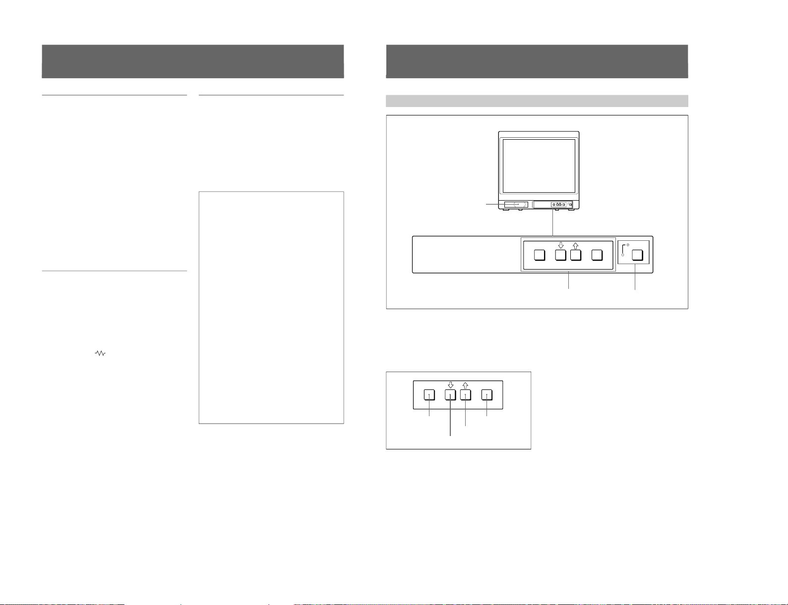
1-20
4
1) Trinitron
“Trinitron” is a registered trademark of Sony Corporation.
2) NTSC
4.43
The NTSC
4.43
system refers to an NTSC color system in which the subcarrier frequency is modified to 4.43 MHz. When an
NTSC recorded video program is played back with a Trident (PAL/SECAM/NTSC
4.43
) VTR, the NTSC
4.43
signal is output.
Features
Picture
Fine pitch Trinitron
1)
picture tube
The fine pitch Trinitron tube provides a high resolution
picture. Horizontal resolution is more than 500 TV
lines at the center of the picture.
Comb filter
When NTSC video signals are received, a comb filter
activates to make more accurate Y/C separation. This
contributes to less of a decrease in resolution, cross
color and cross luminance phenomena.
Beam current feedback circuit
The built-in beam current feedback circuit assures
stable white balance.
Four color system available
The monitor can display NTSC, PAL, SECAM, and
NTSC
4.43
2)
signals. The appropriate color system is
selected automatically.
Input
Y/C input connector
The video signal, split into the chrominance signal (C)
and the luminance signal (Y), can be input through this
connector, eliminating the interference between the
two signals, which tends to occur in a composite video
signal, ensuring video quality.
Automatic termination
(connector with
mark only)
The input connector is terminated at 75 ohms inside
when no cable is connected to the loop-through output
connector. When a cable is connected to an output
connector, the 75-ohm termination is automatically
released.
Functions
On-screen menus
You can set monitor operation settings by using the
on-screen menus.
EIA standard 19-inch rack mounting
By using an MB-502B mounting bracket (for a 14-inch
monitor, not supplied) or SLR-103A slide rail (for a
20-inch monitor, not supplied), the monitor can be
mounted in an EIA standard 19-inch rack.
Attention – when the product is installed in a rack:
•Elevated operating ambient temperature
If installed in a closed or multi-unit rack
assembly, the operating ambient temperature of
the rack environment may be greater than room
ambient.
Therefore, consideration should be given to
installing the equipment in an environment
compatible with the manufacturer’s maximum
rated ambient temperature of 0 to +35 ºC (Tmra).
•Reduced air flow
Installation of the equipment in a rack should be
such that the amount of air flow required for safe
operation of the equipment is not compromised.
•Mechanical loading
Mounting of the equipment in the rack should be
such that a hazardous condition is not achieved
due to uneven mechanical loading.
•Circuit overloading
Consideration should be given to the connection
of the equipment to the supply circuit and the
effect that overloading of circuits might have on
overcurrent protection and supply wiring.
Appropriate consideration of equipment
nameplate ratings should be used when
addressing this concern.
•Reliable earthing
Reliable earthing of rack-mounted equipment
should be maintained. Particular attention should
be given to supply connections other than direct
connections to the branch circuit (e.g., use of
power strips).
..........................................................................................................................................................................................................
5
Location and Function of Parts and Controls
Front
ENTER
MENU/
EXIT
POWER
ENTER
MENU/
EXIT
POWER
1
Speaker
2
MENU buttons
3
UPOWER switch
and indicator
ENTER
MENU/
EXIT
MENU/EXIT button
. button
> button
ENTER button
1 Speaker
2 MENU buttons
Press to make the menu appear.
For detailed information on MENU buttons, see “Operation
through On-Screen Menus” on page 9.
3 UPOWER switch and indicator
Press to turn the monitor on. The indicator lights in
green.
To turn the power off, press this again.
SIIA Chassis
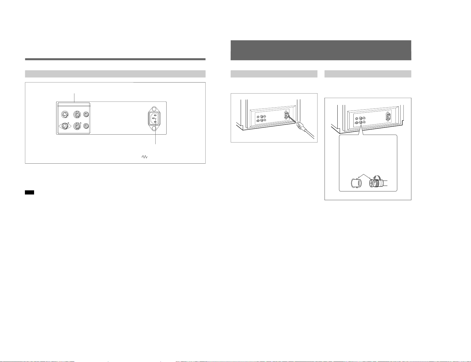
SIIA Chassis
6
Rear Panel
Location and Function of Parts and Controls
1 LINE connectors
Input connectors for the composite video, Y/C separate
video and audio signals and their loop-through output
connectors.
Note
The Y/C IN connector has priority over the VIDEO IN
connector.
When connecting the cable to the Y/C IN connector,
the Y/C IN connector is automatically selected and the
VIDEO IN connector is disconnected even if the cable
is connected.
Y/C IN connector (4-pin mini-DIN)
Connect to the Y/C separate output connector of a
video camera, VCR or other video equipment.
Y/C OUT connector (4-pin mini-DIN)
Loop-through output of the Y/C IN connector.
Connect to the Y/C separate input connector of a VCR
or another monitor.
When the cable is connected to this connector, the 75ohm termination of the input is automatically released,
and the signal input to the Y/C IN connector is output
from this connector.
VIDEO IN connector (BNC-type)
Connect to the video output connector of video
equipment, such as a VCR or a color video camera.
For a loop-through connection, connect to the video
output connector of another monitor.
VIDEO OUT connector (BNC-type)
Loop-through output of the VIDEO IN connector.
Connect to the video input connector for a VCR or
another monitor.
When the cable is connected to this connector, the 75ohm termination of the input is automatically released,
and the signal input to the VIDEO IN connector is
output from this connector.
AUDIO IN connector (phono jack)
Connect to the audio output connector of a VCR or
other equipment. For a loop-through connection,
connect to the audio output of another monitor.
AUDIO OUT connector (phono jack)
Loop-through output of the AUDIO IN connector.
Connect to the audio input connector of a VCR or
another monitor.
2 ⁄AC IN (inlet) connector
Connect the supplied AC power cord to this connector
and to a wall outlet.
(The mark indicates automatic termination.)
2
⁄AC IN connector
1
LINE connectors
LINE ~ AC IN
Y/CINVIDEOINAUDIO
IN
OUT OUT OUT
7
Connections
How to Connect the AC Power Cord
Connect the AC power cord (supplied) to the ⁄AC IN
connector and to a wall outlet.
Insert the connector into
the BNC connector on the
rear panel, matching the
slit and pin, and turn the
cable BNC connector
clockwise to secure the
BNC connector of a
coaxial cable.
How to Connect a Cable to a BNC Connector
Connect the coaxial cable with the BNC connectors to
the BNC connectors on the rear panel as illustrated
below.
1-21
 Loading...