

Page 1
3-862-500-02(1)
Projector
Suspension Support
プロジェクターサスペンションサポート
特約店様用取付説明書
お買い上げいただきありがとうございます。
お客様へ
この取付説明書は、特約店様用に書かれたものです。
警告
お客様が取付説明書に記載された取付工事を行うと、事故などにより死亡や大けがにつな
がることがあります。お客様自身では絶対に取付工事をしないでください。取り付けにつ
いては必ずお買い上げ店またはソニーのサービス窓口にご依頼ください。
特約店の方は、取り付けを安全に行うために、必ずこの説明書をよくお読みください。
Installation manual for Dealers
Manuel d’installation destiné aux revendeurs
Installationshandbuch für Händler
Manual de instalación para proveedores
Manuale d’installazione per i rivenditori
¶wÀª°©˙Æ—gæP©±•Œ
PSS-600
1998 by Sony Corporation
Page 2
日本語
English
耐用荷重:最大
PSS-600 はソニーの LCD データプロジェクターVPL-X600J、
VPL-S600J などの天井吊り下げ用サスペンションサポートで
す。
10 kg
安全のために
下記の注意事項を守らないと、死亡
警告
製品の落下による死亡、大けがなどの
事故を避けるため、下記の注意事項を
強制
必ずお守りください。
・ 設置は、ソニーサービス窓口またはお買い上げ店にご依頼ください。
・ 天井は少なくとも60kgの重量を支えられるように、必要に応じ
て補強を行ってください。
・ ブラケットを天井に直接取り付ける場合には、天井に合わせて、
市販のM10ボルトとナット、ワッシャーをご使用ください。
M10以外のボルト、ナット、ワッシャーで取り付けると落下する
危険があります。
・ 取り付けは手順に従ってください。手順に従わないと落下する危
険や、死亡・大けがになることがあります。
・ PSS-600はソニーのLCDデータプロジェクターの天井吊り下げ
用サスペンションサポートです。それ以外の用途には使用しない
でください。
や大けがになることがあります。
Maximum load: 10 kg (22 lb 1 oz)
The PSS-600 suspension support is designed
to be
used with the Sony VPL-X600U/E/M or VPL-S600U/
E/M LCD data projector, etc.
Caution
• For installation, consult with qualified Sony
personnel.
• The ceiling should be capable of supporting a
weight of at least 60 kg (132 lb 4 oz); if not, the
ceiling must be reinforced.
• When you attach the bracket directly to the
ceiling, use commercially available M10 bolts
with nuts and washers, depending on the
ceiling. Use of other bolts, nuts, and washers
other than M10 may present a danger of falling.
• Be sure to assemble and attach the bracket in
the order indicated; otherwise the projector may
fall.
• The PSS-600 suspension support is designed
for use with Sony LCD data projector. Never
use it for another purpose.
Français
Charge maximale: 10 kg (22 lb 1 oz)
Le support de suspension PSS-600 est conçu pour être
utilisé avec le projecteur de données LCD VPLX600U/E/M ou le VPL-S600U/E/M, etc. de Sony.
Attention
• Pour l’installation, adressez-vous à un personnel
Sony qualifié.
• Le plafond doit pouvoir supporter un poids d’au
moins 60 kg (132 lb 4 oz) ; dans le cas
contraire, il y a lieu de renforcer le plafond.
• Lorsque vous attachez le support directement au
plafond, utilisez des boulons M10 disponibles
dans le commerce avec les écrous et rondelles,
en fonction du plafond. L’utilisation de boulons,
écrous et rondelles différents peut représenter
un danger de chute.
• Assemblez et fixez le support dans l’ordre
indiqué; sinon, le projecteur risque de tomber.
• Le support de suspension PSS-600 est conçu
pour être utilisé avec un projecteur de donées à
cristaux liquides Sony. Ne l’utilisez jamais à
d’autres fins.
2
Deutsch
Maximale Belastbarkeit: 10 kg
Die Aufhängung PSS-600 ist zur Verwendung mit
den LCD-Datenprojektoren VPL-X600E und VPLS600E, usw. von Sony konzipiert.
Vorsicht
• Wenden Sie sich bei der Installation an
qualifizierte Fachkräfte von Sony.
• Die Decke sollte für eine Tragfähigkeit von
mindestens 60 kg ausgelegt ist. Andernfalls muß
die Decke verstärkt werden.
• Wenn Sie die Halterung direkt an der Decke
befestigen, verwenden Sie handelsübliche M10Schrauben mit Muttern und Unterlegscheiben (je
nach Decke). Wenn Sie keine M10-Schrauben, Muttern und -Unterlegscheiben verwenden,
besteht die Gefahr, daß das Gerät herunterfällt.
• Achten Sie darauf, die Halterung in der
angegebenen Reihenfolge zu montieren und
anzubringen. Andernfalls kann der Projektor
herunterfallen.
• Die Aufhängung PSS-600 wurde speziell für
den LCD-Datenprojektor von Sony konzipiert.
Verwenden Sie sie ausschließlich für diesen
Projektor.
Page 3
Español
Italiano
Carga máxima: 10 kg (22 lb 1 oz)
El soporte de suspensión PSS-600 está diseñado para
utilizarse con el proyector de datos LCD VPLX600U/E/M o el VPL-S600U/E/M, etc. de Sony.
Precaución
• Para realizar la instalación, consulte con
personal Sony especializado.
• El techo debe ser capaz de soportar un peso de
al menos 60 kg (132 lb 4 oz) . De no ser así, es
necesario reforzarlo.
• Al fijar el soporte directamente en el techo,
utilice pernos M10, disponibles en las tiendas
del ramo, con tuercas y arandelas en función del
techo. El uso de pernos, tuercas y arandelas que
no sean M10 puede presentar peligro de caída.
• Asegúrese de montar y fijar el soporte en el
orden indicado, ya que en caso contrario es
posible que el proyector se caiga.
• El soporte de suspensión PSS-600 está diseñado
para utilizarse con el proyector de datos LCD de
Sony. No lo utilice para ningún otro propósito.
Portata massima: 10 kg
Il supporto di sospensione PSS-600 è progettato per
essere utilizzato sia con il proiettore di dati LCD
VPL-X600E o il VPL-S600E, etc.
Attenzione
• Per l’installazione, consultare personale
qualificato Sony.
• Il soffitto deve essere in grado di sopportare un
peso di almeno 60 kg. Altrimenti il soffitto
dovrà essere rinforzato.
• Per l’applicazione della staffa direttamente al
soffitto, utilizzare bulloni, dadi e rondelle di
tipo M10, comunemente disponibili in
commercio, in funzione del soffitto. L’uso di
altri tipi di bulloni, dadi e rondelle potrebbe
rappresentare un pericolo di caduta.
• Assicurarsi di montare ed applicare la staffa
seguendo l’ordine indicato. Diversamente il
proiettore potrebbe cadere.
Il supporto di sospensione PSS-600 è stato
•
progettato per essere utilizzato con il proiettore
di dati LCD Sony. Non utilizzarlo per altri scopi.
§§§Â
çj t ¸ q°G10kg
PSS-600 ƒa¨[•Œ§_ Sony VPL-X600M G¥ º
æ⁄ßκv昩Œ VPL-S600M G¥ º æ⁄ßκv昵•æ˜´¨ -
™` N
• ¶w À¿ – Sony § •q™ ±M~ßfi N§H ˚ i¶Ê -
• §—™·™O¿ ¶§‰ºµ 60 kg •H§W ´q™ ؇§O°M¶p
¶ • n°M –•[±j§ß -
• ±N¶Q¨[™ ±µÀ¶b§—™·™O§WÆ…°M –Æ⁄’u§—™·™O™
˛´¨®œ•Œ•´ ‚™ M10 ¡ÆÍ°N¡•¿©M‘È -•Œ
M10 •H•~™ ¡ÆÍ°N¡ •¿©M ‘È©T©w´h¶ ®§U
™¶M¿I-
• ™` N• ´ˆ ”´¸•‹™ ß«©Ó®¯©M¶w À¶Q¨[°Mß_
´hßκv昕H•i؇ |±º ® -
• PSS-600 ƒa¨[ »•Œ©Û Sony µP G¥ º æ⁄ßκv
昰M¨G –§ ±N®‰•Œ©Û®‰•L•ÿ™ -
3
Page 4
目次/Table of contents/Table des matières/Inhalt/
Indice/Indice/•ÿø˝
日本語
部品表....................................................................................... 5
設置寸法................................................................................... 8
天井への取り付けかた.......................................................... 12
天井への取り付け例..............................................................18
主な仕様................................................................................. 22
Français
Composants .............................................................. 5
Schéma d’installation ................................................ 8
Montage au plafond................................................. 13
Exemples d’installation au plafond ..........................18
Spécifications .......................................................... 22
Español
Lista de componentes ............................................... 5
Diagrama de instalación............................................ 8
Montaje en el techo ................................................. 13
Ejemplos de instalación en el techo ........................18
Especificaciones...................................................... 22
English
Parts List ................................................................... 5
Installation Diagram................................................... 8
Attaching to the ceiling ............................................ 12
Installation Examples .............................................. 18
Specifications .......................................................... 22
Deutsch
Teileliste .................................................................... 5
Installationsdiagramm ............................................... 8
Montage an der Decke ............................................ 13
Installationsbeispiele ............................................... 18
Technische Daten ................................................... 22
Italiano
Elenco dei componenti .............................................. 5
Schema dell’installazione ..........................................8
Montaggio al soffitto ................................................ 13
Esempi di installazione al soffitto............................. 18
Caratteristiche tecniche........................................... 22
§§§Â
s°•Û§@ƒ˝™Ì ...................................................................... 5
©w¶Ï§ÿ§o .............................................................................. 8
§—™·™O§W™¶wÀ ................................................................. 13
§—™·™O¶wÀ®“ .................................................................... 18
WÆÊ ................................................................................... 22
4
Page 5
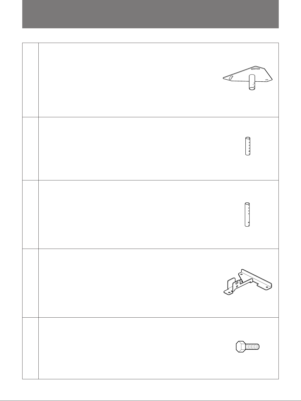
部品表/Parts List/Composants/Teileliste/Lista de
componentes/Elenco dei componenti/ s °•Û§@ƒ˝™Ì
天井用マウントブラケット(1)
Upper ceiling mount bracket (1)
Support supérieur de montage au plafond (1)
Obere Deckenmontagehalterung (1)
(a)
(b)
Soporte superior de montaje en el techo (1)
Staffa superiore di montaggio al soffitto (1)
§W§—™·™O¶wÀ§‰¨[°]1°^
アジャストメントパイプ(1)
Adjustment pipe (1)
Tube de réglage (1)
Einstellrohr (1)
Tubo de ajuste (1)
Tubo di regolazione (1)
’ ` fi°]1°^
(c)
(d)
(e)
アジャストメントパイプ(1)
Adjustment pipe (1)
Tube de réglage (1)
Einstellrohr (1)
Tubo de ajuste (1)
Tubo di regolazione (1)
’ ` fi°]1°^
プロジェクターマウントブラケット(1)
Projector mount bracket (1)
Support de montage du projecteur (1)
Projektormontagehalterung (1)
Soporte de montaje de proyector (1)
Staffa di montaggio del proiettore (1)
ßκvªˆ¶w À§‰¨[°]1°^
ボルトM5×12(3)
Bolt M5 x 12 (3)
Boulon M5 x 12 (3)
Schraube M5 x 12 (3)
Perno M5 x 12 (3)
Bullone M5 x 12 (3)
¡ ÆÍ M5 × 12°]3°^
部品番号/Parts number/
Numéro de pièce/
Teilenummer/
N´umero de componentes/
Numero dei componenti/
s°•Û X
4-063-982-01
5
Page 6
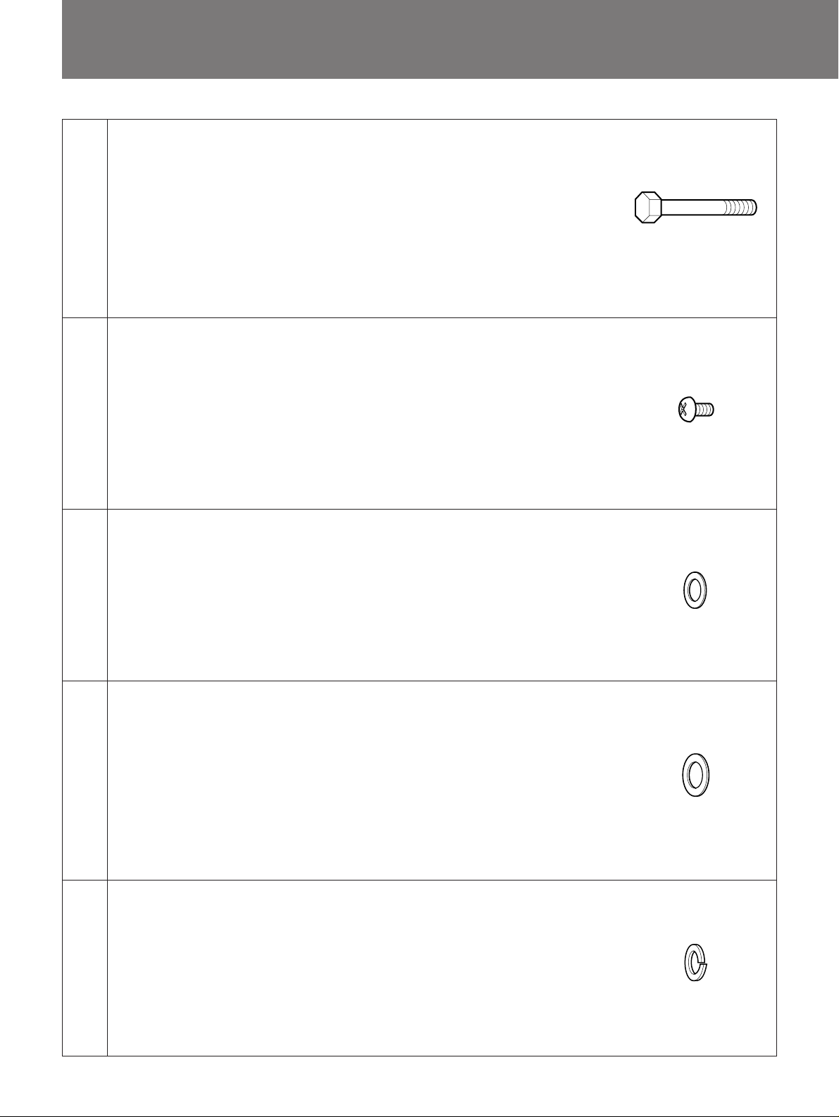
部品表/Parts List/Composants/Teile liste/Lista de componentes/
Elenco dei componenti/ s °•Û§@ƒ˝™Ì
(f)
(g)
(h)
ボルトM8×50(2)
Bolt M8 x 50 (2)
Boulon M8 x 50 (2)
Schraube M8 x 50 (2)
Perno M8 x 50 (2)
Bullone M8 x 50 (2)
¡ ÆÍ M8°—50°]2°^
ネジM4×6(6)
Screw M4 x 6 (6)
Vis M4 x 6 (6)
Schraube M4 x 6 (6)
Tornillo M4 x 6 (6)
Vite M4 x 6 (6)
¡ ÆÍ M4°—6°]6°^
ワッシャーM5用(3)
Washer M5 (3)
Rondelle M5 (3)
Unterlegscheibe M5 (3)
Arandela M5 (3)
Rondella M5 (3)
‘ È M5°]3°^
部品番号/Parts number/
Numéro de pièce/
Teilenummer/
N´umero de componentes/
Numero dei componenti/
s°•Û X
4-047-746-11
部品番号/Parts number/
Numéro de pièce/
Teilenummer/
N´umero de componentes/
Numero dei componenti/
s°•Û X
4-047-765-11
部品番号/Parts number/
Numéro de pièce/
Teilenummer/
N´umero de componentes/
Numero dei componenti/
s°•Û X
4-063-983-01
ワッシャーM8用(4)
部品番号/Parts number/
Numéro de pièce/
Teilenummer/
N´umero de componentes/
Numero dei componenti/
s°•Û X
4-047-748-11
部品番号/Parts number/
Numéro de pièce/
Teilenummer/
N´umero de componentes/
Numero dei componenti/
s°•Û X
4-063-984-01
(i)
(j)
Washer M8 (4)
Rondelle M8 (4)
Unterlegscheibe M8 (4)
Arandela M8 (4)
Rondella M8 (4)
‘ È M8°]4°^
スプリング ワッシャーM5用(3)
Spring washer M5 (3)
Rondelle frein M5 (3)
Federscheibe M5 (3)
Arandela de resorte M5 (3)
Rondella a molla M5 (3)
ºu¬Æ ‘ È M5°]3°^
6
Page 7
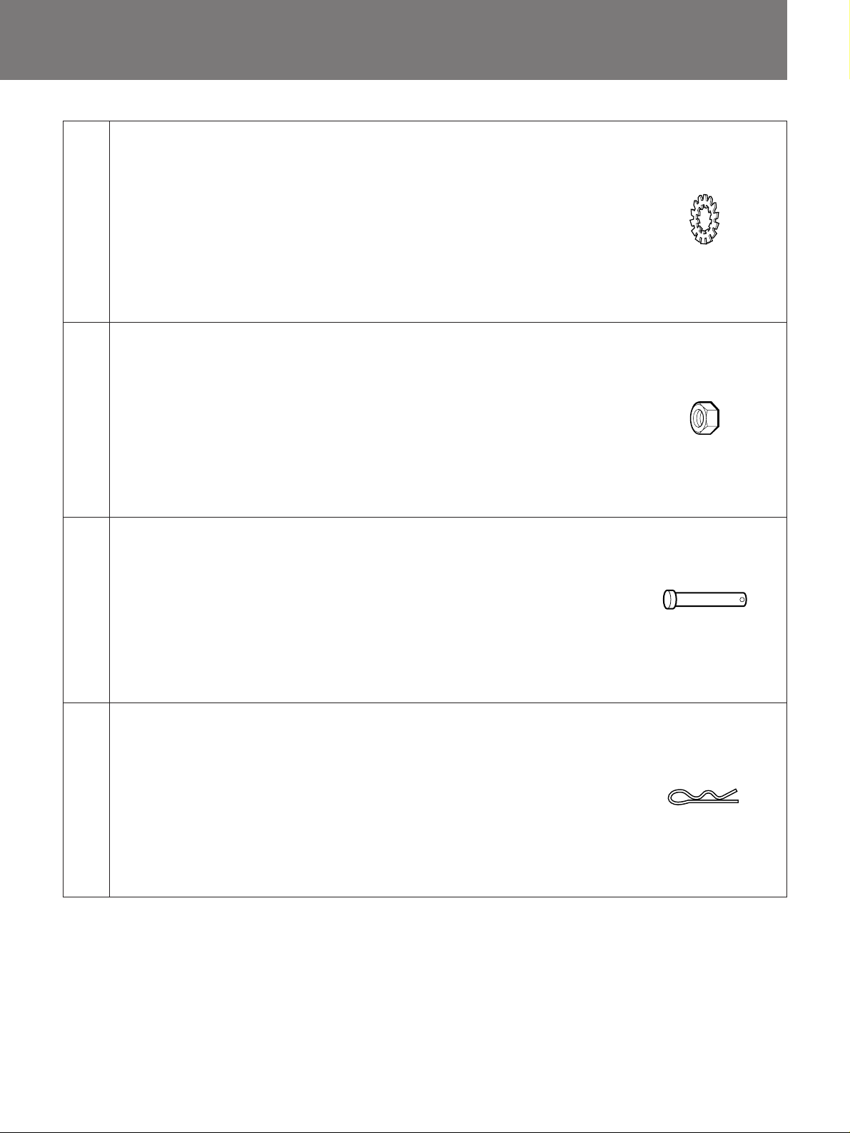
(k)
歯付きワッシャーM8用(4)
Toothed lock washer M8 (4)
Rondelle hélice M8 (4)
Zahnscheibe M8 (4)
Arandela de bloqueo dentada M8 (4)
Rondella di fermo a denti M8 (4)
ø˜æ¶ ‘ È M8°]4°^
部品番号/Parts number/
Numéro de pièce/
Teilenummer/
N´umero de componentes/
Numero dei componenti/
s°•Û X
4-047-743-11
(l)
(m)
(n)
ナットM8(2)
Nut M8 (2)
Ecrou M8 (2)
Mutter M8 (2)
Tuerca M8 (2)
Dado M8 (2)
¡ •¿ M8°]2°^
ピン6mm(2)
6 mm pin (2)
Goupille 6 mm (2)
6-mm-Stift (2)
Pasador de 6 mm (2)
Piedino da 6 mm (2)
6mm ¥° w°]2°^
スナップピン(2)
Snap pin (2)
Clavette à ressort (2)
Klammer (2)
Pasador de retención (2)
Piedino ad incastro (2)
ß® w°]2°^
部品番号/Parts number/
Numéro de pièce/
Teilenummer/
N´umero de componentes/
Numero dei componenti/
s°•Û X
4-047-742-11
部品番号/Parts number/
Numéro de pièce/
Teilenummer/
N´umero de componentes/
Numero dei componenti/
s°•Û X
4-047-744-11
部品番号/Parts number/
Numéro de pièce/
Teilenummer/
N´umero de componentes/
Numero dei componenti/
s°•Û X
4-047-903-11
7
Page 8

設置寸法/Installation Diagram/Schéma d’installation/
Installationsdiagramm/
スクリーンサイズと投射距離の寸法については、以下の説明書をご覧ください。
-取扱説明書
-設置説明書
- レンズの取付説明書(別売のレンズ使用時)
For details of screen size and installation measurement for projection, refer to the following manuals:
- Operating Instructions
- Installation Manual for Dealers
- Installation Manual of the projection lens (when using the optional lens)
Pour plus de détails sur le format d’écran et la distance de projection, consultez les manuels ci-dessous:
- Mode d’emploi
- Manuel d’installation destiné aux revendeurs
- Manuel d’installation de l’objectif (lors de l’utilisation de l’objectif optionnel)
Genaue Angaben zu Projektionsschirmgröße und Installationsmaßen für die Projektion entnehmen Sie bitte den
unten gezeigten Anweisungen:
- Bedienungsanleitung
- Installationsanleitung für Händler
- Installationshandbuch zum Objektiv (bei Verwendung des gesondert erhältlichen Objektivs)
Para obtener información detallada sobre el tamaño de pantalla y las medidas de instalación para proyección,
consulte los manuales como sigue:
- Manual de instrucciones
- Manual de instalación para proveedores
- Manual de instalación del objetivo de proyección (al utilizar el l’obiettivo opzionale)
Per informazioni dettagliate sulla dimensione dello schermo e le misure di installazione del proiettore, fare
riferimento ai manuali come dimostrato qui sotto:
- Istruzioni per l’uso
- Manuale d’installazione per irivenditori
- Manuale d’installazione dell’obiettivo (quando si utilizza l’obiettivo opzionale)
¶ ˆßκv昙 ´Ã ı§ÿ§o©M¶w À¥˙q™ ‘”±°™p°M – —æ\•H§Uª°©˙Æ— -
- ®œ•Œª°©˙Æ—
- gæP©±¶w À§‚•U
- ßκv z Ë™ ¶wÀª°©˙Æ—°]®œ•ŒøÔ¡™ z ËÆ…°^
8
Page 9
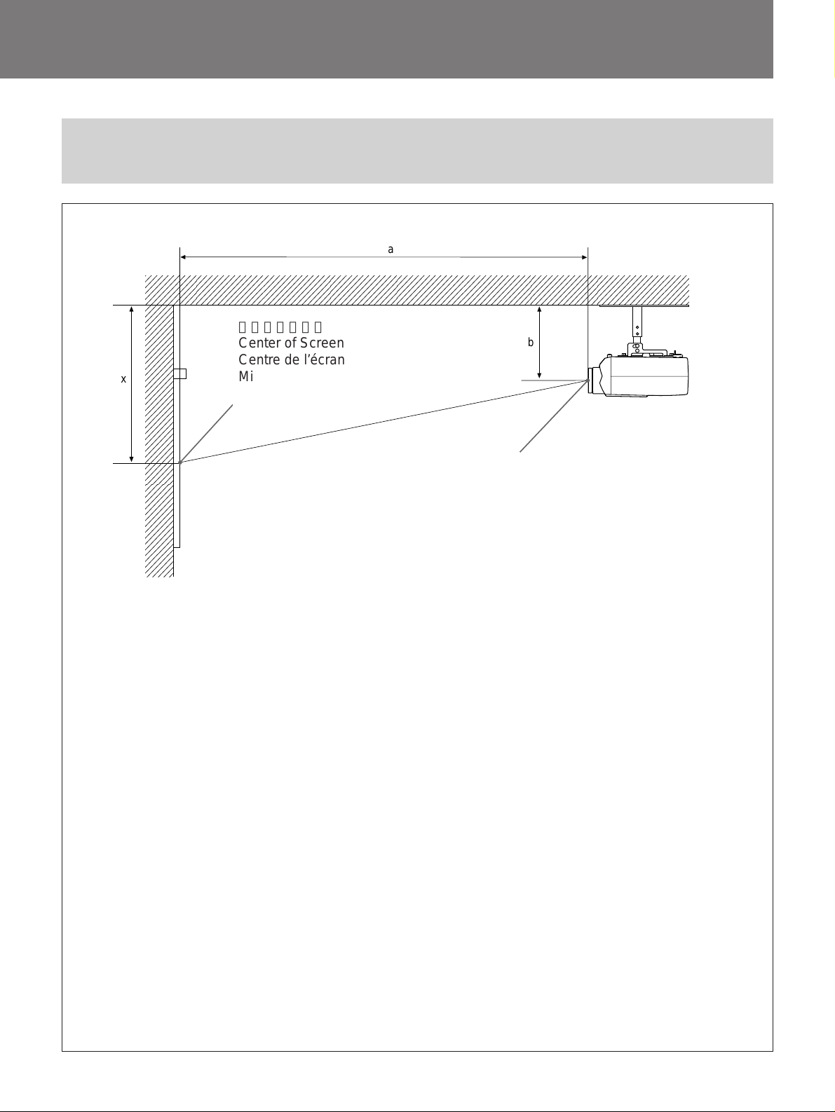
Diagrama de instalación/Schema dell’installazione/
©w¶Ï§ÿ§o
横から見た図/Side view/Vue latérale/Seitenansicht/Vista lateral/
Vista laterale/
x
ºµ¯ œ
スクリーン中心
Center of Screen
Centre de l’écran
Mitte des Projektionsschirms
Centro de la pantalla
Centro dello schermo
´Ã ı§§•°
a
レンズ中心
Center of lens
Centre de l’objectif
Mitte des Objektivs
Centro del objetivo
Centro della lente
Ë¿Y§§§fl
天井
Ceiling
Plafond
b
プロジェクター
Projector
Projecteur
Projektor
Proyector
Proiettore
ßκvæ˜
Decke
Techo
Soffitto
§—™·™O
壁/Wall/Mur/Wand/Pared/
Muro/¿æ¿
a: スクリーンからレンズ中心までの距離/Distance between the screen and the center of lens/
Distance entre l’écran et le centre de l’objectif/Abstand zwischen dem Projektionsschirm und der
Mitte des Objektivs /Distancia entre la pantalla y el centro del objetivo/Distanza fra lo schermo e il
centro della lente/´Ã ı©M Ë¿Y§§§fl§ß °™ Z¬˜
b: 天井からレンズ中心までの距離。詳しくは11ページをご覧ください。/Distance between the
ceiling and the center of lens. For details, see page 11. /Distance entre le plafond et le centre de
l’objectif. Pour plus de détails, reportez-vous à la page 11. /Abstand zwischen der Decke und der
Mitte des Objektivs. Näheres dazu finden Sie auf Seite 11. /Distancia entre el techo y el centro del
objetivo. Para obtener información detallada, consulte la página 11. /Distanza fra il soffitto e il
centro della lente. Per dettagli, vedere a pagina 11. /§—™·™O©M Ë¿Y§§§fl§ß°™ Z¬˜ -¶ ˆ®‰ ‘ ”ª°
©˙°M – —æ\ ƒ 11 -
x: 天井からスクリーン中心までの距離/Distance between the ceiling and the center of screen/
Distance entre le plafond et le centre de l’écran/Abstand zwischen der Decke und der Mitte des
Projektionsschirms/Distancia entre el techo y el centro de la pantalla/Distanza fra il soffitto e il
centro dello schermo/§—™·™O©M´Ã ı§§§fl§ß °™ Z¬˜
9
Page 10
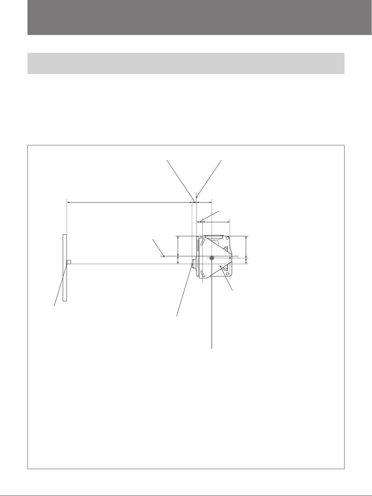
設置寸法/Installation Diagram/Schéma d’installation/
Installationsdiagramm/Diagrama de instalación/
上から見た図/Top view/Vue du dessus/Draufsicht/Vista superior/Vista
dall’alto/
¡µ¯ œ
プロジェクターのレンズの中心とスクリーンの中心が合うよ
うに 設 置してください 。
Align the center of the lens with the center of the
screen.
Alignez le centre de l’objectif sur le centre de l’écran.
Richten Sie die Mitte des Objektivs an der Mitte des
Projektionsschirms aus.
38*
1
(1
/2)*
a
本体中心
Center of the unit
Centre de l’appareil
Mitte des Geräts
Centro de la unidad
Centro dell’apparecchio
ßκv昧§§fl
166.5
(6
57.5
(21/4)
9
/16)
Alinee el centro del objetivo con el centro de la
pantalla.
Allineare il centro della lente con il centro dello
schermo.
–±Nßκvæ˜ Ë¿Y™ §§§flªP´Ã ı™§§§fl ÔªÙ -
キャビネット前面
Front of the cabinet
Avant du meuble
Vorderseite des Gehäuses
Parte frontal de la caja
Parte anteriore dell’apparecchio
133
(51/4)
春fl´e ±
61(213/32)
216.6(817/32)
175(67/8)
49(1
15
/16)
天井用マウントブラケット
Upper ceiling mount bracket
スクリーン中心
Center of the Screen
Centre de l’écran
Mitte des Projektionsschirms
Centro de la pantalla
Centro dello schermo
´Ã ı§§§fl
単位:mm
Units : mm (inches)
Unité : mm (pouces)
Einheit : mm
Unidades : mm (pulgadas)
Unità : mm
ʶϰG mm
* VPL-X600J/S600J本体標準レンズ使用時
* When using the standard lens equipped with VPL-X600U/E/M / S600U/E/M
* Si vous utilisez l’objectif standard qui équipe le VPL-X600U/E/M / S600U/E/M
* Installation mit dem Standardobjektiv des VPL-X600E / S600E
* Al emplear el objetivo estándar equipado con el VPL-X600U/E/M / S600U/E/M
* Quando si utilizza l’obiettivo standard in dotazione con il VPL-X600E / S600E
* ®œ•Œ VPL-X600M / S600M t ™ º–« Ë¿YÆ…
レンズ中心
Center of the lens
Centre de I’objectif
Mitte des Objektivs
Centro del objetivo
Centro della lente
Ë¿Y§§§fl
支柱の中心(支柱の中心は、本体中心とは異なります)
Center of the supporting pole (The center of the
supporting pole is different from that of the unit)
Centre du pivot de support (Le centre du pivot de
support est différent de celui de l’appareil)
Mitte des Ständers (Die Mitte des Ständers entspricht
nicht der des Geräts)
Centro de la columna de soporte (El centro de la
columna de soporte no es el mismo que el de la unidad)
Centro per l’asta di supporto (Il centro per l’asta di
supporto è diverso da quello dell’apparecchio)
§‰¨W§§§fl°]§‰¨W§§§flªPßκv昙 §§§fl§£¶P°^
Support de montage de plafond supérieur
Deckenmontagehalterung
Soporte de montaje superior para techo
Staffa di montaggio al soffitto
§—™·™Oø§¨E¶Q¨[
10
Page 11
Schema dell’installazione/©w¶Ï§ÿ§o
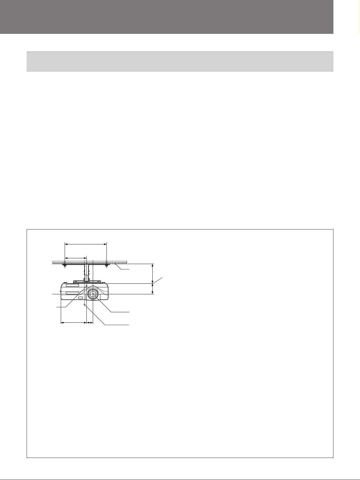
前から見た図/Front view/Vue frontale/Vorderansicht/Vista frontal/Vista
frontale/
•øµ¯ œ
レンズの中心は、支柱の中心より右側に4 9 mmずれていま
す。天井に設置するときは、支柱の中心ではなくレンズの中
心とスクリーンの中心を合わせてください。
The lens is offset 49 mm (1 15/16 inches) to the right
from the center of the supporting pole. When
mounting, take care to align the center of the lens
with the center of the screen; not the center of the
supporting pole.
15
L’objectif est décalé de 49 mm (1
/16 pouces) vers la
droite du centre du pivot de support. Au moment du
montage, veillez à aligner correctement le centre de
l’objectif sur le centre de l’écran; pas le centre du pivot
de support.
Das Objektiv am Projektor ist 49 mm nach rechts von
der Mitte des Ständers versetzt. Achten Sie beim
Installieren darauf, die Mitte des Objektivs, nicht die
Mitte des Ständers, an der Mitte des
Projektionsschirms auszurichten.
250(927/32)
125
29
(4
/32)
1
4
175
(67/8)49(115/16)
1 天井/Ceiling/Plafond/Decke/Techo/Soffitto/§—™·™O
2 レンズ中心/Center of the lens/Centre de l’objectif/Mitte des
Objektivs/Centro del objetivo/Centro della lente/ Ë¿Y§§§fl
3 本体中心/Center of the unit/Centre de l’appareil/
Mitte des Geräts/Centro de la unidad/Centro
dell’apparecchio/ßκv昧§§fl
2
3
d
5
76(3)
単位:mm
Units : mm (inches)
Unité : mm (pouces)
Einheit : mm
Unidades : mm (pulgadas)
Unità : mm
ʶϰG mm
15
El objetivo está desplazado 49 mm (1
/16pulgadas) a
la derecha del centro de la columna de soporte. Al
realizar el montaje, alinee el centro del objetivo con
el centro de la pantalla y no con el centro de la
columna de soporte.
Rispetto al centro per l’asta di supporto, la lente del
proiettore è spostata verso destra di 49 mm. Durante
il montaggio, assicurarsi di allineare il centro della
lente del proiettore e non il centro per l’asta di
supporto con il centro dello schermo.
Ë¿Y•—ßκv昧‰¨[™ §§§fl¶V•kºææ 49 mm-
¶wÀÆ…°M–±NË¿Y™§§§fl°]¶”´Dßκv昶Q¨[™ §§§fl°^ªP´Ã ı™
§§§fl ÔªÙ -
d: 天井からプロジェクターマウントブラケット取り付け面間での
距離
アジャストメントパイプ(b)を使った場合:150/175/200mm
アジャス トメン トパイプ (c) を使った場合:250/275/300mm
Distance between the ceiling and the surface of the mounting bracket
Using adjustment pipe (b) : 150/175/200 mm (6/7/7 7/8 inches)
Using adjustment pipe (c) : 250/275/300 mm (9 7/8 /10 7/8 /11 7/8 inches)
Distance entre le plafond et la surface du supprt de montage
Utilisation du tube de réglage (b): 150/175/200 mm (6/7/7 7/8 pouces)
Utilisation du tube de réglage (c): 250/275/300 mm (9 7/8 /10 7/8 /11 7/8
pouces)
Abstand zwischen der Decke und der Oberlfäche der Hlaterung
Mit Einstellrohr (b): 150/175/200 mm
Mit Einstellrohr (c): 250/275/300 mm
Distancia entre el techo y la base del proyector
Uso del tubo de ajuste (b): 150/175/200 mm (6/7/7 7/8 pulgadas)
Uso del tubo de ajuste (c): 250/275/300 mm (9 7/8 /10 7/8 /11 7/8 pulgadas)
Distanza fra il soffitto e la superficie della staffa di montaggio
Utilizzando il tubo di regolazione (b): 150/175/200 mm
Utilizzando il tubo di regolazione (c): 250/275/300 mm
§—™·™O©Mßκv昶wÀ§‰¨[§ß¶wÀ¶”§ß °™ Z¬˜
®œ•Œ ’ ` fi°] b°^°J150/175/200 mm
®œ•Œ ’ ` fi°] c°^°J250/275/300 mm
4 支柱の中心/Center of the supporting pole/Centre du pivot de
support/Mitte des Ständers/Centro de la columna de
soporte/Centro per l’asta di supporto/§‰¨W§§§fl
5 プロジェクターマウントブラケット取り付け面/The bottom
surface of the mounting bracket /Le dessous du support de
montage /Die Unterseite der Halterung /La base del la
superficie del soporte de montaje /La superficie inferiore
della staffa di montaggio/ßκv昶w À¶Q¨[§ß¶w À ±
11
Page 12
天井への取り付けかた/Attaching to the ceiling/
Montage au plafond/Montage an der Decke/
1
(j)
(h)
(d)
(e)
(e)
(j)
(h)
プロジェクター底面
Bottom of projector
Base du projecteur
Unterseite des Projektors
Base del proyector
Base del proiettore
ßκv昩 ±
2
(f)
(i)
(k)
(b)/(c)
(d)
(k)
(i)
(l)
日本語
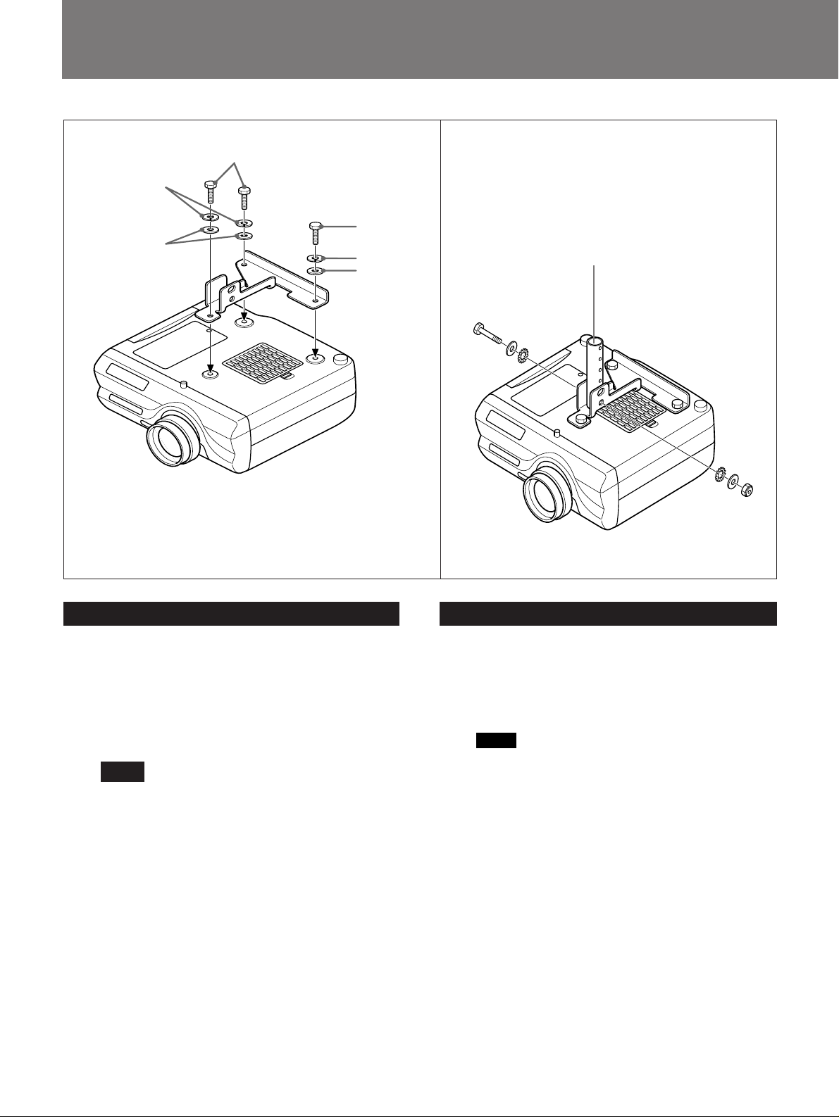
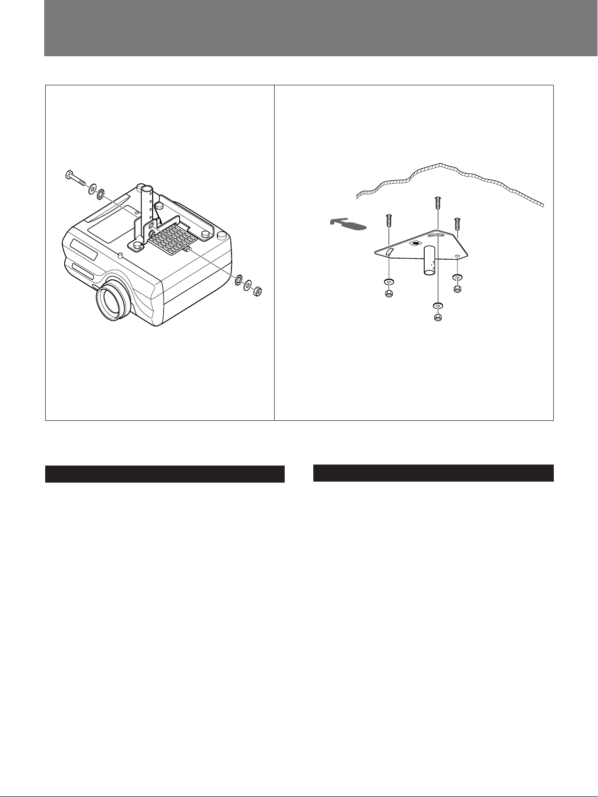
1 プロジェクターを裏返し、プロジェクターマウントブ
ラケット(d) を取り付ける。
ボルトM5× 12(e)(3 本)、ワッシャーM5 用(h)(3
本)、スプリングワッシャーM5 用 (j)(3 本)を使用し
ます。
ご注意
• 取り付けの際に、ボルトをきつく締め すぎないよう
に注意してください。
• プロジェクターや机に傷 が つか ないよう布などを敷
いた上で作業を行ってください。
2 アジャストメン トパイプ (b) または (c) をプロジェク
ターマウントブラケット(d) に取り付ける。
ボルトM8×50 (f)(1 本)、ワッシャーM8 用 (i)(2
本)、歯付きワッシャーM8 用 (k)(2 本)、ナットM8
(l)(1本)を使用します。パイプ (b) は 150/175/200
mm、パイプ (c) は250/275/300mmの範囲で高さを調
節できます。
English
1 Turn the projector upside down and attach the
projector mount bracket (d) using three bolts M5 x
12 (e), three washers M5 (h) and three spring
washers M5 (j).
Notes
• When attaching the bracket, be careful not to
overtighten the bolts.
• Before attaching the projector mount bracket,
place a protective sheet (cloth) beneath the
projector.
2 Attach adjustment pipe (b) or (c) to projector mount
bracket (d) using a bolt M8 x 50 (f), two washers
M8 (i), two thoothed lock washers M8 (k) and a nut
M8 (l).
Adjustable height using the pipe (b) is 150/175/200
mm (6/7/7 7/8 inches).
Adjustable height using the pipe (c) is 250/275/300
mm (9 7/8 /10 7/8 /11 7/8 inches).
12
Page 13
Montaje en el techo/Montaggio al soffitto/
§—™·™O§W™¶wÀ
Français
1 Retournez le projecteur et fixez le support de
montage du projecteur (d) à l’aide de trois boulons
M5 x 12 (e), de trois rondelles M5 (h) et de trois
rondelles frein M5 (j).
Remarques
• Lors de l’installation du support de montage,
veillez à ne pas trop serrer les boulons.
• Avant de fixer le support de montage du
projecteur, placez une protection (chiffon) sous le
prejecteur.
2 Fixez le tube de réglage (b) ou (c) sur le support de
montage (d) à l’aide d’un boulon M8 x 50 (f), de
deux rondelles M8 (i), de deux rondelles hélice M8
(k) et d’un écrou M8 (l).
La hauteur de réglage avec le tube (b) est de 150/
175/200 mm (6/7/7 7/8 pouces)
La hauteur de réglage avec le tube (c) est de 250/
275/300 mm (9 7/8 /10 7/8 /11 7/8 pouces)
Español
1 Dele la vuelta al proyector y fije el soporte de
montaje de proyector (d) con tres pernos M5 x 12
(e), tres arandelas M5 (h) y tres arandelas elásticas
M5 (j).
Notas
• Al fijar el soporte, tenga cuidado de no apretar
excesivamente los pernos.
• Antes de fijar el soporte de montaje de proyector,
coloque un paño de protección debajo del
proyector.
2 Fije el tubo de ajuste (b) o (c) al soporte de montaje
(d) con uno perno M8 x 50 (f), dos arandelas M8
(i), dos arandelas de bloqueo dentadas M8 (k) y una
tuerca M8 (l).
La altura ajustable empleando el tubo (b) es de 150/
175/200 mm (6/7/7 7/8 pulgadas).
La altura ajustable empleando el tubo (c) es de 250/
275/300 mm (9 7/8 /10 7/8 /11 7/8 pulgadas).
Deutsch
1 Drehen Sie den Projektor um, und bringen Sie die
Projektormontagehalterung (d) mit drei M5 x 12Schrauben (e), drei M5-Unterlegscheiben (h) und
drei M5-Federscheiben (j) an.
Hinweise
• Achten Sie beim Anbringen der Halterung darauf,
die Schrauben nicht zu fest anzuziehen.
• Legen Sie eine Schutzfolie oder ein Tuch unter den
Projektor, bevor Sie die
Projektormontagehalterung anbringen.
2 Bringen Sie das Einstellrohr (b) oder (c) mit einer
M8 x 50-Schraube (f), zwei M8-Unterlegscheiben
(i), zwei M8-Zahnscheiben (k) und einer M8-Mutter
(l) an die Projektormontagehalterung (d) an.
Die mit Rohr (b) einstellbare Höhe beträgt 150/175/
200 mm.
Die mit Rohr (c) einstellbare Höhe beträgt 250/275/
300 mm.
Italiano
1 Capovolgere il proiettore ed applicare la staffa di
montaggio (d) usando tre bulloni M5 x 12 (e), tre
rondelli M5 (h) e tre rondelli elastiche M5 (j).
Note
• Durante l’applicazione della staffa, assicurarsi di
non serrare eccessivamente i bulloni.
• Avanti di applicare la staffa di montaggio, porre un
foglio (telo) di protezione sotto il proiettore.
2 Applicare il tubo di regolazione (b) o (c) alla staffa
di montaggio del proiettore (d) usando uno bullone
M8 x 50 (f), due rondelli M8 (i), due rondelli di
fermo a denti M8 (k) e uno dado M8 (l).
Utilizzando il tubo (b), l’altezza è regolabile di 150/
175/200 mm.
Utilizzando il tubo (c), l’altezza è regolabile di 250/
275/300 mm.
§§§Â
1 ¬ ¬‡ßκv昰M À§Wßκv昶w À¶Q¨[°] d°^-
®œ•Œ 3 ”¡ ÆÍ M5 × 12°]e°^°N ‘ È M5°]h°^©M 3
”ºu¬Æ ‘ È M5°]j°^-
™` N
• ¶wÀ¶Q¨[Æ…°M–§±N¡ ÆÍ¿æ±o LÚ -
• ¶w Àßκv昶w À¶Q¨[§ß´e°M –•˝¶bßκv昧U ‘§W§@±i
´O @Ø»°]©Œ•¨°^ -
2 •Œ®‚ ”¡ ÆÍ M8 × 50°]f°^°N®‚”‘È M8°]i°^°N
®‚ ”ø˜æ¶ ‘ È M8°]k°^©M§@ ”¡ •¿ M8°]l°^±N ’
` fi°] b°^©Œ°]c°^ À¶b¶w À¶Q¨[°] d°^§W’`fi °]b°^•i¶b 150/175/200 mm ™dÚ§’`
™´ -’`fi °]c°^•i¶b 250/275/300 mm ™dÚ
§ ’`™´ -
13
Page 14
天井への取り付けかた/Attaching to the ceiling/
Montage au plafond/Montage an der Decke/Montaje en el techo/
3
(f)
(i)
(k)
(d)
(k)
(i)
(l)
4
スクリーン方向
Screen forward
Ecran
Projektionsschirm
Pantalla
Direzione dello
schermo
´Ã ı§Ë¶V
(a)
日本語
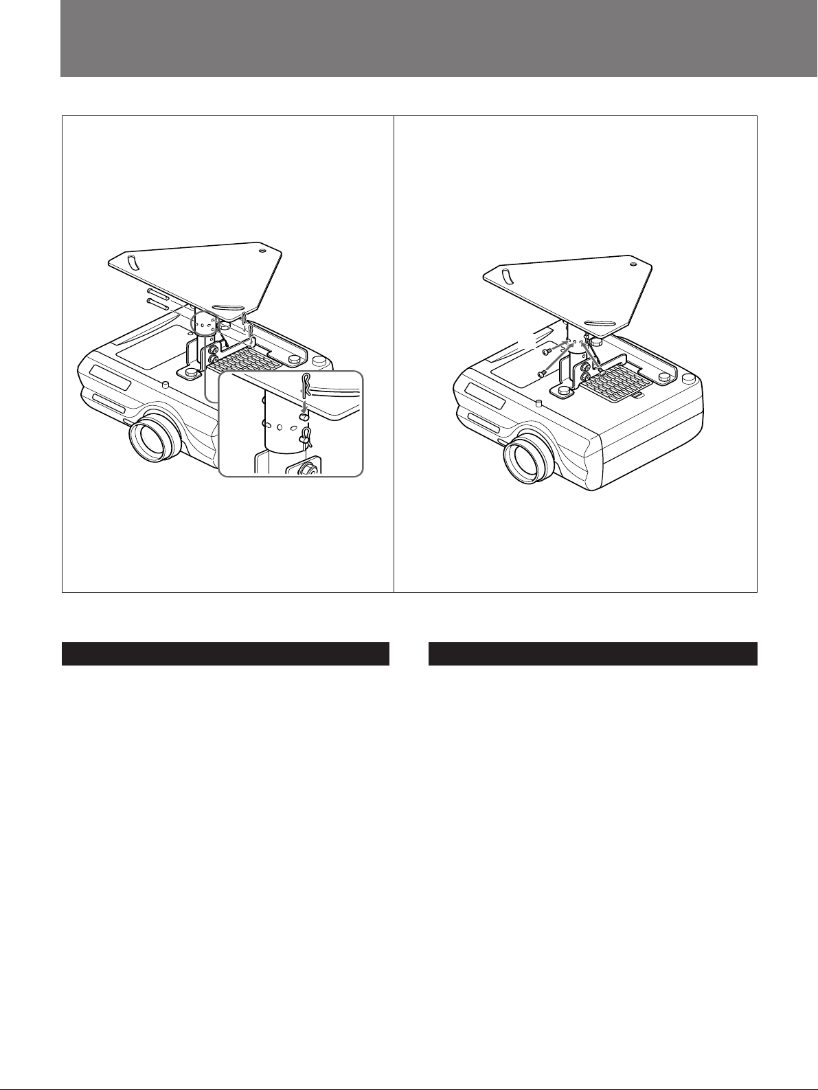
3 プロジェクターマウントブラケット(d) にアジャスト
メン トパ イプを 仮ど め す る。
プロジェクターが 水 平になるように取り付けます。
角度を多少調整することもできますが、この場合投
影される画面は台形になります。
ボルトM8×50 (f)(1 本)、歯 付きワッ シャー M 8 用
(k)(2 本)、ワッシャーM8 用 (i)(2本)、ナットM8
(l)(1 本)を使用します。
4 天井用マウントブラケッ ト ( a ) を天井に取り付ける。
市販の M 1 0 ボルト、ナット、ワッ シャーをご使用く
ださい 。
English
3 Attach the adjustment pipe to the projector mount
bracket (d) using a bolt M8 x 50 (f), two toothed
lock washers M8 (k), two washers M8 (i) and a nut
M8 (l).
Attach the pipes so that the projector becomes level.
You may tilt the projector slightly, but this will
make the projected picture trapezoidal.
4 Attach the upper ceiling mount bracket (a) to the
ceiling.
Use M 10 bolts, nuts and washers (not supplied).
14
Page 15

Montaggio al soffitto/§—™·™O§W™ ¶w À
Français
3 Montez les tubes de réglage sur le support de
montage du projecteur (d) à l’aide d’un boulon M8 x
50 (f), de deux rondelles hélice M8 (k), de deux
rondelle M8 (i) et d’un écrou M8 (l).
Fixez les tubes de façon à mettre le projecteur à
niveau. Vous pouvez incliner légèrement le
projecteur, mais cette opération donnera un aspect
trapézoïdal à l’image projetée.
4 Fixez le support de suspension (a) au plafond.
Utilisez des boulons, des écrous et des rondelles M
10 (non fournis).
Español
3 Fije el tubo de ajuste al soporte de montaje de
proyector (d) con uno perno M8 x 50 (f), dos
arandelas de bloqueo dentadas M8 (k), dos arandelas
M8 (i) y una tuerca M8 (l).
Fije los tubos observando que el proyector quede
nivelado. Aunque es posible inclinar ligeramente el
proyector, tenga en cuenta que esto producirá que la
imagen proyectada aparezca con forma trapezoidal.
Deutsch
3 Bringen Sie das Einstellrohr mit einer M8 x 50-
Schraube (f), zwei M8-Zahnscheiben (k), zwei M8Unterlegscheiben (i) und einer M8-Mutter (l) an die
Projektormontagehalterung (d) an.
Stellen Sie die Rohre so ein, daß der Projektor
waagerecht hängt. Sie können den Projektor
leicht neigen, aber dann nimmt das projizierte
Bild die Form eines Trapezes an.
4 Bringen Sie die Deckenmontagehalterung (a) an der
Decke an.
Verwenden Sie M10-Schrauben, - Muttern und Unterlegscheiben (nicht mitgeliefert).
Italiano
3 Applicare il tubo di regolazione staffa di montaggio
del proiettore (d) usando uno bullone M8 x 50 (f),
due rondelli di fermo a denti M8 (k), due rondelli
M8 (i) e uno dado M8 (l).
Montare i tubi di regolazione in modo da sospendere
il proiettore in modo equilibrato. È possibile
inclinare leggermente il proiettore, ma l’immagine
proiettata avrà una forma trapezoidale.
4 Fije el soporte de montaje superior (a) en el techo.
Emplee arandelas, tuercas y pernos M 10 (no
suministrados).
§§§Â
3 •Œ§@ ”¡ ÆÍ M8 × 50°]f°^°N®‚ ”ø˜æ¶ ‘ È M8
°]k°^°N®‚”‘È M8°]i°^©M§@ ”¡ •¿ M8°]l°^±N
’ ` fi À¶bßκv昶w À¶Q¨[ °] d°^§W]m’`fi®œßκv昧ٕ ƒa¨E -±z•i•H®œßκvæ˜
µy L …± °M¶˝ o |®œßκvµe ±ße±Ëߌ -
4 ±Nƒa¨E¶Q¨[°]a°^ À¶b§—™·™O§W -
®œ•Œ M10 ¡ ÆÍ°N¡ •¿©M ‘ È°]•º™˛±a°^ -
4 Applicare la staffa di montaggio (a) al soffitto.
Usare bulloni, dadi e rondelle M 10 (non in
dotazione).
15
Page 16
天井への取り付けかた/Attaching to the ceiling/
Montage au plafond/Montage an der Decke/Montaje en el techo/
5
6
(a)
(m)
(n)
(g)
日本語
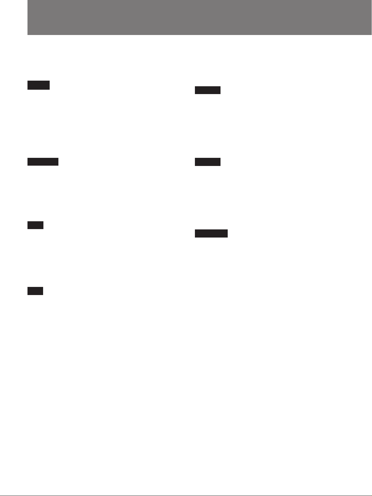
5 アジャス トメン トパ イプ を 天 井 用 マウン トブラケット
( a) に差し込み、仮どめする。
ピン 6 mm(m)(2 本)とスナッ プピン (n)(2 本)を使
用します。パイプ (b)は150/175/200mm、パイプ(c)は
250/275/300 mmの範囲で高さを調節できます。
6 手順5 で仮どめした天井用マウントブラケッ ト (a)とア
ジャストメントパイプを固定 する。
ネジM4 × 6 (g)(6 本)を使用します。
次に手 順 3 で仮どめしたボ ルトをきつく締め て、ア
ジャストメントパイプを固定します。
English
5 Insert the adjustment pipe into the upper ceiling
mount bracket (a). Attach the pipe with the two 6
mm pins (m) and the two snap pins (n).
Pipe (b) can be adjusted to a height of 150/175/200
mm (6/7/7 7/8 inches); pipe (c) can be adjusted to a
length of between 250/275/300 mm (9 7/8 /10 7/8 /11
7
/8 inches).
6 Secure the ceiling mount bracket (a) and the
adjustment pipe you attached in step 5.
Use six M4 × 6 bolts (g).
Then, tighten the bolts you attached in step 3 to
secure the adjustment pipe.
16
Page 17

Montaggio al soffitto/§—™·™O§W™¶wÀ
Français
5 Introduisez le tube de réglage dans le support de
suspension au plafond (a). Fixez le tube à l’aide de
deux goupilles de 6 mm (m) et de deux clavettes à
ressort (n).
Le tube (b) peut se régler selon une hauteur de 150/
175/200 mm (6/7/7 7/8 pouces); le tube (c) peut se
régler selon une longueur de 250/275/300 mm (9 7/8 /
10 7/8 /11 7/8 pouces).
6 Fixez le support de montage au plafond (a) et le tube
d’ajustement qui sont attachés à l’étape 5.
Utilisez six boulons M4 × 6 (g).
Serrez ensuite les boulons que vous avez insérés à
l’étape 3 pour fixer le tube d’ajustement.
Español
5 Inserte el tubo de ajuste en el soporte de montaje de
techo (a). Fije el tubo con dos pasadores de 6 mm
(m) y dos pasadores de retención (n).
El tubo (b) puede ajustarse a una altura de 150/
175/200 mm (6/7/7
el (c) puede ajustarse a una longitud
comprendida entre 250/275/300 mm(9
/11 7/8 pulgadas).
7
/8 pulgadas), mientras que
7
/8 /10 7/8
Deutsch
5 Setzen Sie das Einstellrohr in die
Deckenmontagehalterung (a) ein. Bringen Sie das
Rohr mit den zwei 6-mm-Stiften (m) und den zwei
Klammern (n) an.
Rohr (b) kann auf eine Länge von 150/175/200
mm eingestellt werden, Rohr (c) auf eine Länge
von 250/275/300 mm.
6 Sichern Sie die in Schritt 5 angebrachten
Deckenmontagehalterung (a) und das Einstellrohr.
Verwenden Sie dazu die sechs Schrauben M4 × 6 (g).
Ziehen Sie dann die in Schritt 3 angebrachten
Schrauben an, um das Einstellrohr zu sichern.
Italiano
5 Inserire il tubo di regolazione all’interno della staffa
di sospensione (a). Applicare il tubo con due piedini
di 6 mm (m) e due piedini a ad incastro (n).
Il tubo (b) può essere regolato ad una lunghezza
variabile fra 150/175/200 mm e il tubo (c) può
essere regolato ad una lunghezza variabile fra 250/
275/300 mm.
6 Asegure el soporte de montaje de techo (a) y el tubo
de ajuste que ha montado en el paso 5.
Emplee seis pernos M4 × 6 (g).
A continuación, apriete los pernos que ha montado
en el paso 3 para fijar el tubo de ajuste.
§§§Â
5 ±N ’ ` fi¥°§J§—™·™Oƒa¨E¶Q¨[°] a°^¶}•Œ®‚ ” 6
mm ¥° w°] m°^©M®‚ ”ß® w°] n°^©T©w¶Ì’`fi -
’ ` fi°] b°^•i¶b 150/175/200 mm §ß °°]•H 25
mm ° j°^ ’ `°Q ’ ` fi°] c°^•i¶b 250/275/ 300
mm §ß°’` -
6 •Œ 6 ¡˚ M4 × 6 ¡ÆÍ°]g°^©T©w§—™·™O•Œ¶w À¶Q¨[
°]a°^©M¶b ƒ 5 ®B À§W™ ’ ` fi -
µM´·¿æ Ú¶b ƒ 3 ®B¶w§W™¡ ÆÍ°M®©T©w ’ ` fi -
6 Fissare la staffa di montaggio al soffitto (a) e il tubo
di regolazione applicati al passo 5.
Usare sei bulloni M4 × 6 (g).
Serrare quindi i bulloni applicati al passo 3 in modo
da fissare il tubo di regolazione.
17
Page 18
天井への取り付け例/Installation Examples/Exemples
d’installation au plafond/Installationsbeispiele/
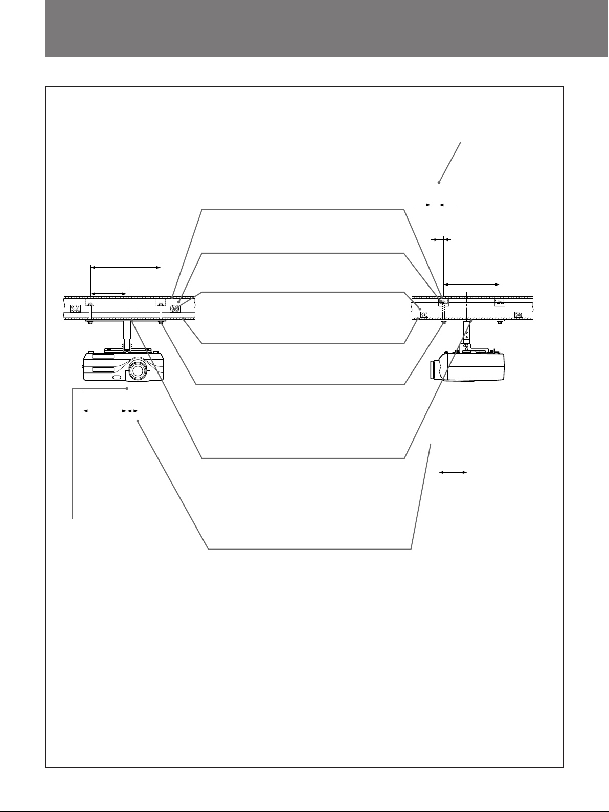
以下はサスペンションサポートが天井に取り付けられたとき
の様子を示します。天井の材質によって補強方法は多少異な
りま す 。
ご注意
取り付ける前に天井の最大耐用荷重が6 0 kg以上あることをお
確かめください。
Les illustrations suivantes représentent le support de
suspension du projecteur fixé au plafond.
L’installation s’effectue différemment en fonction de
la constitution du plafond.
Remarque
Vérifiezque la charge maximale du plafond soit
suérieure à 60 kg (132 lb 4 oz) avant l’installation.
Las siguientes ilustraciones muestran el soporte de
suspensión para proyector fijado al techo. La
instalación varía en función del material del techo.
Nota
Compruebe la capacidad de carga máxima del techo
sea superior a 60 kg (132 lb 4 oz) antes de realizar la
instalación.
The following illustrations show the projector
suspension support attached to with the ceiling.
Installation is different depending on the material of
ceiling.
Caution
Before installation, check that the maximum ceiling
loading is in excess of 60 kg (132 lb 4 oz) .
In den Abbildungen unten ist dargestellt, wie die
Projektoraufhängung an der Decke angebracht wird.
Die Installation unterscheidet sich je nach Material
der Decke.
Hinweis
Überprüfen Sie vor der Installation, ob die maximale
Belastbarkeit der Decke mindestens 60 kg beträgt.
Le seguenti illustrazioni mostrano il montaggio al
soffitto del supporto di sospensione del proiettore. La
procedura di installazione varia a seconda del tipo di
soffitto.
Attenzione
Prima di procedere con l’installazione, verificare che
il peso massimo di portata del soffitto sia superiore a
60 kg.
§Uœœ•‹¶b§—™·™O§W¶wÀƒa¨[™§Ë™k-¶wÀ§Ë™k¶]§—™·™Oߘƶ”
ß-
™`N
¶w À´e°M –•˝¿À¨d§—™·™O™ çj ¸´ q¨Oß_¶b 60 kg •H§W-
18
Page 19

Ejemplos de instalación en el techo/Esempi di
installazione al soffitto/§—™·™O¶w À®“
板天井に取り付ける場合/For wooden ceiling/Pour un plancher/Montage an
einer Holzdecke/Para techos de madera/Montaggio ad un soffitto in legno/
¶wÀ§_§Ïªs§—™·™O§W™ ı¶X
平屋または最上階の場合/For-one-story house or uppermost floor/Pour maison à un étage ou plafond
sous un toit/Decke eines einstöckigen Hauses oder des obersten Stockwerks/ Para casas de una
planta o plantas superiores/Montaggio in una casa a piano unico o all’ultimo piano/ •Œ§_• ©–©Œ ªº”
キャビネット前面
Front of the
cabinet
Avant du meuble
Vorderseite des
Gehäuses
Parte frontal de la
caja
Parte anteriore
dell’apparecchio
春fl´e ±
(1
38*
1
/2)*
補強材/Reinforcing material/Matériau de renfort/
Verstärkungsmaterial/Mterial de refuerzo/
250
(927/32)
125
29
(4
/32)
49
15
/16)
(1
175
7
(6
/8)
支柱中心
Center of the supporting pole
Centre du pivot de support
Mitte des Ständers
Centro de la columna de soporte
Centro per l’asta di supporto
ßκv昧§§fl
* VPL-X600J/S600J本体標準レンズ使用時
* When using the standard lens equipped with VPL-X600U/E/M / S600U/E/M
* Si vous utilisez l’objectif standard qui équipe le VPL-X600U/E/M / S600U/E/M
* Installation mit dem Standardobjektiv des VPL-X600E / S600E
* Al emplear el objetivo estándar equipado con el VPL-X600U/E/M / S600U/E/M
* Quando si utilizza l’obiettivo standard in dotazione con il VPL-X600E / S600E
* ®œ•Œ VPL-X600M / S600M t ™ º– «Ë¿YÆ…
Materiale di rinforzo/ºW±jߘÆ
梁(5×20cm)/Roof beam (2” x 8”) /Traviesa
(2” x 8”) /Trägerbalken (ca. 5 x 20 cm) /Viga de
techo (2” x 8”) /Trave del soffitto (circa 5 x 20
cm.) /©–±Á°]5 × 20 cm°^
天井/Ceiling line/Niveau du plafond/Deckenlinie/
Línea de techo/Livello del soffitto/§—™·™O
ナットとワッシャーで締めたM10ボルト/
M10 bolt with nut and washer/Boulon M10 avec
écrou et rondelle/M10-Schraube mit Mutter und/
Perno M10 con tuerca y arandela/Bullone M10
con dado e rondella/•Œ¡ •¿©M ‘È¿æ Ú™ M10
¡ÆÍ
天井用マウントブラケット
Upper ceiling mount bracket
Support de montage de plafond supérieur
Deckenmontagehalterung
Soporte de montaje superior para techo
Staffa di montaggio al soffitto
§—™·™Oƒa¨E¶Q¨[
レンズ中心
Center of the lens
Centre de I’objectif
Mitte des Objektivs
Centro del objetivo
Centro della lente
Ë¿Y§§§fl
61
(213/32)
216.6
17
(8
/32)
133(51/4)
単位:mm
Units : mm (inches)
Unité : mm (pouces)
Einheit : mm
Unidades : mm (pulgadas)
Unità : mm
くぎ
Nail
Clou
Nagel
Punta
Chiodo
§§l
ʶϰG mm
19
Page 20
天井への取り付け例/Installation Examples/Exemples d’installation
au plafond/Installationsbeispiele/
その他の階の場合/For other floors/Autres sols/Zwischendecken/Para otros suelos/Per altri piani/
®‰•Lºh™ ı¶X
125
29
(4
(9
/32)
250
27
/32)
38*
(1
上の階の床
/Floor line/Niveau du plancher/
Bodenlinie/Línea de suelo/Livello del
pavimento/§W§@ºh™¶a™O
梁
/Joist (2” x 8”) /Traverse/Deckenbalken
(ca. 5 x 20 cm) /Traviesa (2” x 8”) /
Travetto(circa 5 x 20 cm.) /©–±Á°]5 × 20 cm°^
梁(5×20cm)
/Roof beam (2” x 8”) /
Tra v e r s e ( 2 ” x 8 ” ) /Trägerbalken (ca. 5 x 2 0
cm) /Viga de techo (2” x 8”) /Trave del soffitto
(circa 5 x 20 cm.) /©–±Á°]5 × 20 cm°^
1
/2)*
キャビネット前面
Front of the cabinet
Avant du meuble
Vorderseite des
Gehäuses
Parte frontal de la
caja
Parte anteriore
dell’apparecchio
春fl´e ±
61
13
(2
/32)
216.6
17
(8
/32)
49
15
/16)
175
(67/8)
支柱中心
(1
Center of the supporting pole
Centre du pivot de support
Mitte des Ständers
Centro de la columna de soporte
Centro per l’asta di supporto
ßκv昧§§fl
/Ceiling line/Niveau du plafond/
天井
Deckenlinie/Línea de techo/Livello del
soffitto/§—™·™O
ナットとワッシャーで締めたM10ボルト/M10
bolt with nut and washer/Boulon M10 avec
écrou et rondelle/M10-Schraube mit Mutter
und Unterlegscheibe/Perno M10 con
tuerca y arandela/Bullone M10 con dado e
rondella/•Œ¡ •¿©M ‘ È¿æÚ™ M10 ¡ÆÍ
天井用マウントブラケット
Upper ceiling mount bracket
Support de montage de plafond supérieur
Deckenmontagehalterung
Soporte de montaje superior para techo
Staffa di montaggio al soffitto
§—™·™Oƒa¨E¶Q¨[
レンズ中心
Center of the lens
Centre de I’objectif
Mitte des Objektivs
Centro del objetivo
Centro della lente
Ë¿Y§§§fl
133(51/4)
*VPL-X600J/S600J本体標準レンズ使用時
*When using the standard lens equipped with VPL-X600U/E/M / S600U/E/M
*Si vous utilisez l’objectif standard qui équipe le VPL-X600U/E/M / S600U/E/M
*Installation mit dem Standardobjektiv des VPL-X600E / S600E
*Al emplear el objetivo estándar equipado con el VPL-X600U/E/M / S600U/E/M
*Quando si utilizza l’obiettivo standard in dotazione con il VPL-X600E / S600E
*®œ•Œ VPL-X600M / S600M t ™ º– «Ë¿YÆ…
20
単位:mm
Units : mm (inches)
Unité : mm (pouces)
Einheit : mm
Unidades : mm (pulgadas)
Unità : mm
ʶϰG mm
Page 21
Ejemplos de instalación en el techo/Esempi di installazione al
soffitto/§—™·™O¶wÀ®“
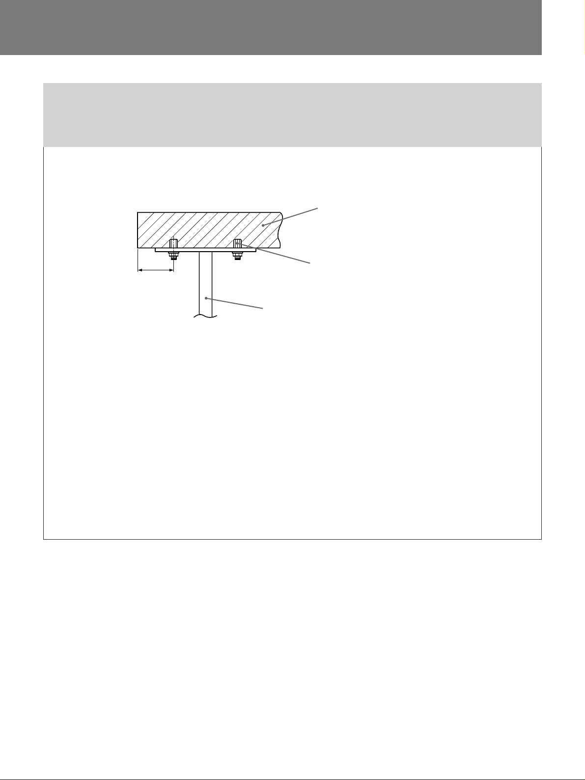
コンクリート天井に取り付ける場合/For concrete ceiling/Pour un plafond en
béton/Betondecke/Para techos de hormigón/Montaggio ad un soffitto di
cemento/
壁端から80mm以上距離を
とってください。
Place bolts at least 80 mm
(3 1/4 inches) away from
wall. /Ecartez les boulons
de 80 mm (3 1/4 pouces)
du mur minimum. /
Schrauben mindestens 80
mm von der Wand entfernt
anbringen. /Coloque los
pernos a una distancia de
al menos 80 mm (3 1/4
pulgadas) delapared./
Collocare i bulloni ad
almeno 80 mm dal muro. /
®œ¡ ÆͪP¿ 濨¤ Z 80 mm
•H§W-
¶bVæƧg§—™·™O§W¶wÀÆ…
プロジェクター
Projector
Projecteur
Projektor
Proyector
Proiettore
ßκvæ˜
コンクリート天井/Concrete ceiling/Plafond en
béton/Betondecke/Techo de hormigón/Soffitto di
cemento/VæƧg§—™·™O
コンクリートアンカー(12mm径以上)/Anchor for
concrete (over 12 mm; 1/2 inch dia.) / Ancrage pour
béton (supérieur à 12 mm; 1/2 pouce de diamètre) /
Betonanker (mehr als 12 mm Durchmesser) /
Anclaje para hormigón (con diámetro superior a 12
mm; 1/2 pulgada) /Catena per cemento (oltre 12
mm di diametro)/VæƧg¡„©T°]™ Æ| 12 mm •H§W°^
天井用マウントブラケット
Upper ceiling mount bracket
Support de montage de plafond supérieur
Deckenmontagehalterung
Soporte de montaje superior para techo
Staffa di montaggio al soffitto
§—™·™Oƒa¨E¶Q¨[
21
Page 22
主な仕様/Specifications/Spécifications/Technische
Daten/Especificaciones/Caratteristiche tecniche/ WÆÊ
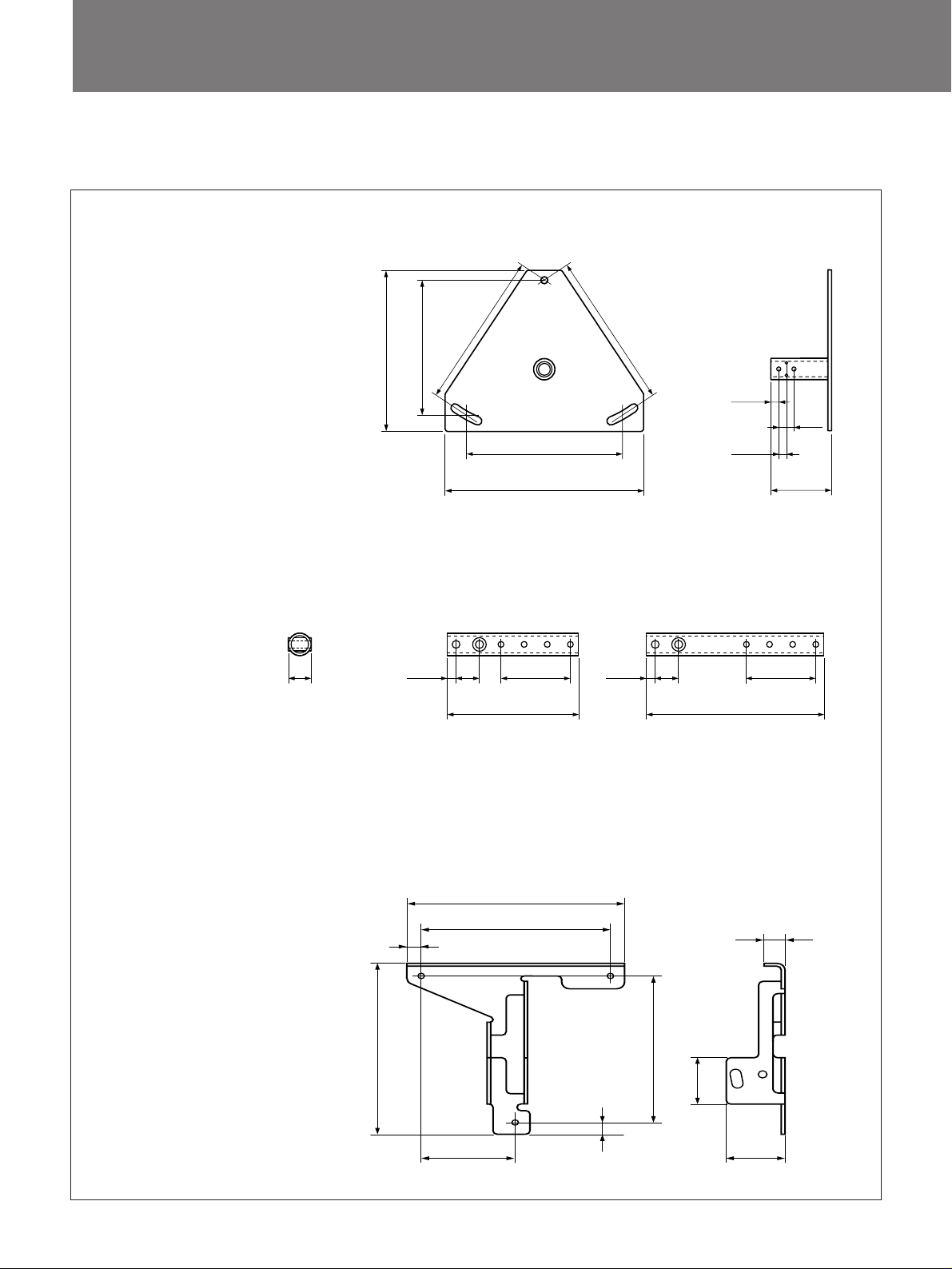
外形寸法/Dimensions/Mesures/Abmessungen/Dimensiones/Dimensioni/§ÿ§o
天井用マウントブラケット
(a)
Upper ceiling mount bracket
Support de suspension au plafond
Deckenhalterung
Soporte de suspensión de techo
/16)
3
250
27
(9
/32)
/32)
17
250(927/32)
Staffa di montaggio al soffitto
§—™·™Oƒa¨E¶Q¨[
216.6(8
258.8(10
27
250(9
317.5(12
アジャストメントパイプ/Adjustment pipes/Tubes de réglage/Einstellrohre/ Tubos de ajuste/Tubi di regolazione/
/32)
1
/2)
12.7(
25(
12.7(
31
1
/2)
/32)
1
/2)
94.8(3
23
/32)
’`fi
(c)
9.5
3
(
/8)
25
31
/32)
(
75
(215/16)
240(97/16)
26(11/32)
(b)
9.5
(3/8)
25
31
(
/32)
140(51/2)
(2
75
15
/16)
プロジェクターマウントブラケット/Projector mount bracket/Support de montage du projecteur/
Projektormontagehalterung/ Soporte de montaje de proyector/Staffa di montaggio del proiettore/
ßκv昶w À¶Q¨[
13
/32)
/16)
15
単位:mm
Units : mm (inches)
(d)
12.7(1/2)
/16)
1
188.4(7
163(613/32)
Unité : mm (pouces)
Einheit : mm
Unidades : mm (pulgadas)
179.1(7
150.6(5
51.1(2)
Unità : mm
ʶϰG mm
81.5(37/32)
12.7(
1
/2)
22
19.1(
52(2
1
/16)
3
/4)
Page 23
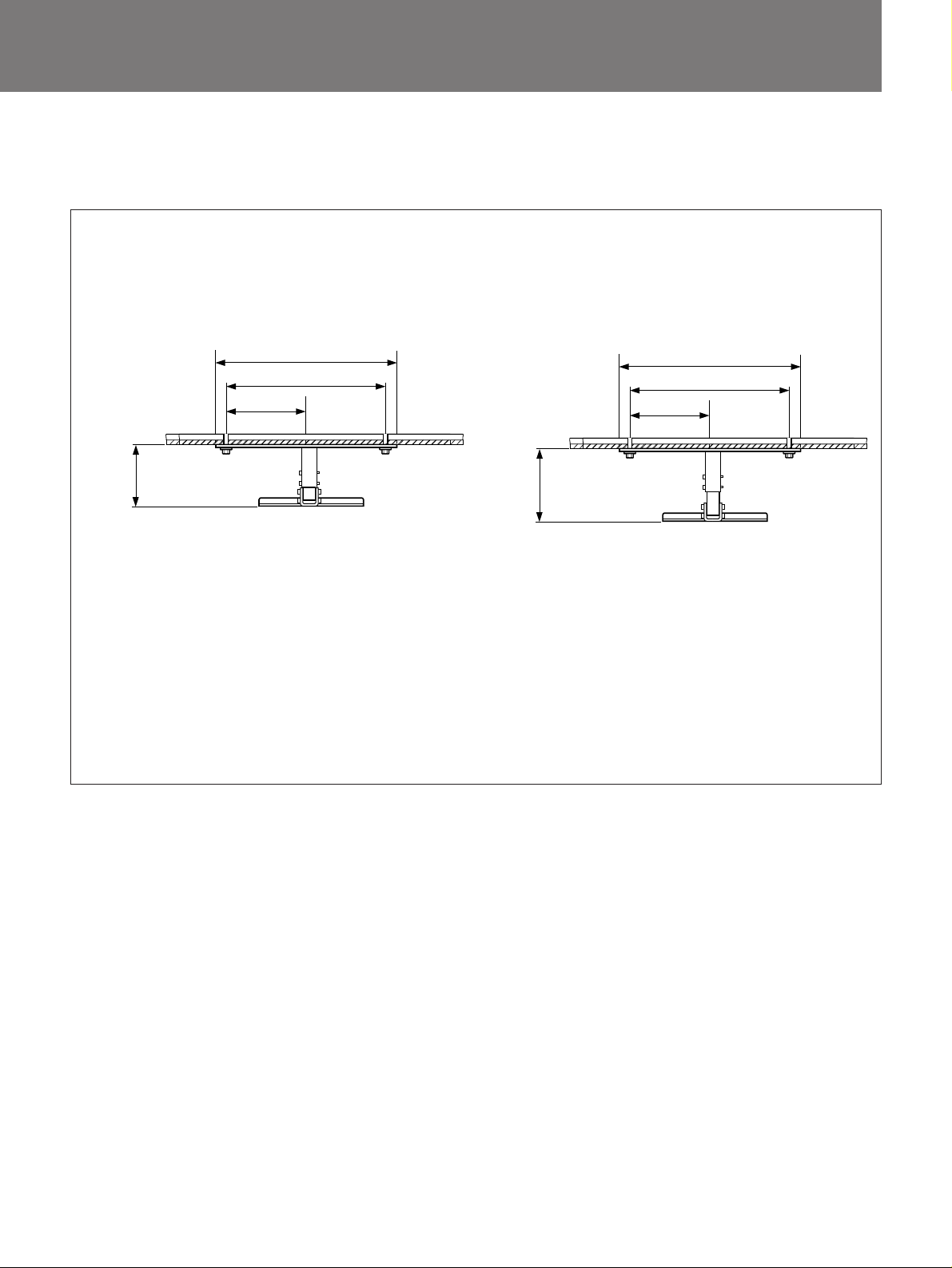
組み上げ時の寸法/Dimensions of the assembled bracket/Dimensions du support assemblé/
Abmessungen de montierten Halterung/Dimensiones del soporte de monitaje/Dimensioni della staffa
montata/¶Q¨[ ’ À´·§ß§ÿ§o
前から見た図/Front view/Vue frontale/Vorderansicht/Vista frontal/Vista frontale/•øµ¯ œ
317.5(121/2)
250(9
125(429/32)
/8)
7
(6/7/7
150/175/200
単位:mm
Units : mm (inches)
Unité : mm (pouces)
Einheit : mm
Unidades : mm (pulgadas)
Unità : mm
ʶϰG mm
27
/32)
/8)
7
/8/11
7
/8/10
7
250/275/300
(9
317.5(12
250(9
29
125(4
/32)
27
1
/2)
/32)
質量 約2.7 kg/Mass Approx. 2.7 kg (5 lb 15 oz) /Poids : 2,7 kg approx. (5 lb 15 oz) /Gewicht : ca. 2,7
kg/Masa: 2,7 kg aprox. (5 lb 15 oz) /Peso approssimativo: 2,7 kg/ ´ q ¨˘ 2.7 kg
耐用荷重 最大10 kg/Loading Maximum loading :10 kg (22 lb 1 oz) /Charge maximale: 10 kg (22 lb 1
oz) /Carga Carga máxima: 10 kg/Carico Carico massimo: 10 kg (22 lb 1 oz) /Portata massima: 10 kg/
çj¸´q 10 kg
仕様および外観は、改良のため予告なく変更することがあり
ますが、ご了承ください。
La conception et les spécifications sont sujettes à
modifications sans préavis.
Diseño y especificaciones sujetos a cambios sin
previo aviso.
•~ߌ§ŒWÆʶp¶ ‹ßÛ°MƧ§£•t¶Êq™æ -
Design and specifications are subject to change
without notice.
Änderungen, die dem technischen Fortschritt dienen,
bleiben vorbehalten.
Il design e le caratteristiche tecniche sono soggetti a
modifiche senza preavviso.
23
Page 24
お問い合わせは
「ソニー業務用製品ご相談窓口のご案内」
ソニー株式会社
ソニーマーケティング株式会社情報システム営業本部
〒
141-0001
〒
108-0074
Printed in U.S.A.
にある窓口へ
東京都品川区北品川6-7-35
東京都港区高輪4-10-18
 Loading...