

Page 1
3-865-453-01(1)
Projector
Suspension Support
プロジェクターサスペンションサポート
特約店様用取付説明書
お買い上げいただきありがとうございます。
お客様へ
この取付説明書は、特約店様用に書かれたものです。
警告
お客様が取付説明書に記載された取付工事を行うと、事故などにより死亡や大けがにつ
ながることがあります。お客様自身では絶対に取付工事をしないでください。取り付け
については必ずお買い上げ店またはソニーのサービス窓口にご依頼ください。
特約店の方は、取り付けを安全に行うために、必ずこの説明書をよくお読みください。
Installation manual for Dealers
Manuel d’installation destiné aux revendeurs
Installationshandbuch für Händler
Manual de instalación para proveedores
Manuale d’installazione per i rivenditori
PSS-2000
1998 by Sony Corporation
Page 2
日本語
Français
耐用荷重:最大50kg
PSS-2000はソニーのLCDデータプロジェクターVPL-X2000Jの天
井吊り下げ用サスペンションサポートで す。
安全のために
下記の注意事項を守らないと、死亡
警告
製品の落下による死亡、大けがなどの
事故を避けるため、下記の注意事項を
強制
必ずお守りください。
・ 設置は、ソニーサービス窓口またはお買い上げ店にご依頼ください。
・ 天井は少なくとも250kgの重量を支えられるように、必要に応
じて補強を行ってください。
・ ブラケットを天井に直接取り付ける場合には、天井に合わせて、
市販のM10 ボルトとナット、ワッシャーをご使用ください。
M10以外のボルト、ナット、ワッシャーで取り付けると落下する
危険があります。
・ 取り付けは手順に従ってください。手順に従わないと落下する危
険や、死亡・大けがになることがあります。
・ PSS-2000はソニーのLCDデータプロジェクターの天井吊り下
げ用サスペンションサポートです。それ以外の用途には使用しな
いでください。
や大けがになることがあります。
Charge maximale: 50 kg (110 lb 6 on)
Le support de suspension PSS-2000 est conçu pour
être utilisé avec les projecteurs de données à cristaux
liquides Sony, tels que le VPL-X2000U/E/M.
Attention
• Pour l’installation, adressez-vous à un personnel
Sony qualifié.
• Le plafond doit pouvoir supporter un poids d’au
moins 250 kg (551 lb 2 on) ; dans le cas contraire,
il y a lieu de renforcer le plafond.
• Lorsque vous attachez le support directement au
plafond, utilisez des boulons M10 disponibles
dans le commerce avec les écrous et rondelles, en
fonction du plafond. L’utilisation de boulons,
écrous et rondelles différents peut représenter un
danger de chute.
• Assemblez et fixez le support dans l’ordre
indiqué; sinon, le projecteur risque de tomber
auquel cas vous courez un risque de blessure
voire un danger de mort.
• Le support de suspension PSS-2000 est conçu
pour être utilisé avec un projecteur de donées à
cristaux liquides Sony. Ne l’utilisez jamais à
d’autres fins.
English
Maximum load: 50 kg (110 lb 6 oz)
The PSS-2000 suspension support is designed for use
with Sony LCD Data projectors the VPL-X2000U/E/M.
Caution
• For installation, consult with qualifies Sony
personnel.
• The ceiling should be capable of supporting a
weight of at least 250 kg (551 lb 2 oz); if not,
the ceiling must be reinforced.
• When you attach the bracket directly to the
ceiling, use commercially available M10 bolts
with nuts and washers, depending on the
ceiling. Use of other bolts, nuts, and washers
other than M10 may present a danger of falling.
• Be sure to assemble and attach the bracket in
the order indicated; otherwise the projector may
fall, resulting in grievous bodily injury or even
death.
• The PSS-2000 suspension support is designed
for use with Sony LCD data projector. Never
use it for another purpose.
Deutsch
Maximale Belastbarkeit: 50 kg
Die Aufhängung PSS-2000 wurde speziell für LCDDatenprojektoren von Sony wie z. B. den
VPL-X2000E konzipiert.
Vorsicht
• Wenden Sie sich bei der Installation an
qualifizierte Fachkräfte von Sony.
• Die Decke muß für eine Tragfähigkeit von
mindestens 250 kg ausgelegt sein. Andernfalls
muß die Decke verstärkt werden.
• Wenn Sie die Halterung direkt an der Decke
befestigen, verwenden Sie handelsübliche M10Schrauben mit Muttern und Unterlegscheiben (je
nach Decke). Wenn Sie keine M10-Schrauben,
-Muttern und -Unterlegscheiben verwenden,
besteht die Gefahr, daß das Gerät herunterfällt.
• Achten Sie darauf, die Halterung in der
angegebenen Reihenfolge zu montieren und
anzubringen. Andernfalls kann der Projektor
herunterfallen. Dabei könnte es zu schweren
Unfällen kommen!
• Die Aufhängung PSS-2000 wurde speziell für
den LCD-Datenprojektor von Sony konzipiert.
Verwenden Sie sie ausschließlich für diesen
Projektor.
2
Page 3
Español
Carga máxima: 50 kg (110 lb 6 oz)
El soporte de suspensión PSS-2000 está diseñado para
emplearse con proyectores de datos LCD de Sony,
como el VPL-X2000U/E/M.
Precaución
• Para realizar la instalación, consulte con personal
Sony especializado.
• El techo debe ser capaz de soportar un peso de al
menos 250 kg (551 lb 2 oz) . De no ser así, es
necesario reforzarlo.
• Al fijar el soporte directamente en el techo, utilice
pernos M10, disponibles en las tiendas del ramo,
con tuercas y arandelas en función del techo. El
uso de pernos, tuercas y arandelas que no sean
M10 puede presentar peligro de caída.
• Asegúrese de montar y fijar el soporte en el orden
indicado, ya que en caso contrarlo es posible que
el proyector se caiga, y puede existir riesgo de
lesiones graves o fallecimiento.
• El soporte de suspensión PSS-2000 está diseñado
para utilizarse con el proyector de datos LCD de
Sony. No lo utilice para ningún otro propósito.
中文
Italiano
Portata massima: 50 kg.
Il supporto di sospensione PSS-2000 è stato concepito
per uso esclusivo con proiettori di dati LCD Sony,
come il modello VPL-X2000E.
Attenzione
• Per l’installazione, consultare personale
qualificato Sony.
• Il soffitto deve essere in grado di sopportare un
peso di almeno 250 kg. Altrimenti il soffitto
dovrà essere rinforzato.
• Per l’applicazione della staffa direttamente al
soffitto, utilizzare bulloni, dadi e rondelle di
tipo M10, comunemente disponibili in
commercio, in funzione del soffitto. L’uso di
altri tipi di bulloni, dadi e rondelle potrebbe
rappresentare un pericolo di caduta.
• Assicurarsi di montare ed applicare la staffa
seguendo l’ordine indicato. Diversamente il
proiettore potrebbe cadere si potrebbero correre
grossi rischi.
• Il supporto di sospensione PSS-2000 è stato
progettato per essere utilizzato con il proiettore
di dati LCD Sony. Non utilizzarlo per altri
scopi.
3
Page 4

目次/Table of contents/Table des matières/Inhalt/
Indice/Indice/
部品表 .........................................................................................................................................................................................................6
設置寸法......................................................................................................................................................................................................8
天井への取り付けかた ........................................................................................................................................................................... 12
天井への取り付け例 ............................................................................................................................................................................... 16
主な仕様................................................................................................................................................................................................... 22
Parts List ................................................................................................................................................................... 6
Installation Diagram .................................................................................................................................................. 8
Attaching to the Ceiling ........................................................................................................................................... 12
Installation Examples .............................................................................................................................................. 16
Specifications .......................................................................................................................................................... 22
Composants .............................................................................................................................................................. 6
Schéma d’installation ................................................................................................................................................ 8
Montage au plafond ................................................................................................................................................ 12
Examples d’installation au plafond.......................................................................................................................... 16
Spécifications .......................................................................................................................................................... 22
Teileliste .................................................................................................................................................................... 6
Installationsdiagramm ............................................................................................................................................... 8
Montage an der Decke............................................................................................................................................ 12
Installationsbeispiele ............................................................................................................................................... 16
Technische Daten ................................................................................................................................................... 22
Lista de componentes ............................................................................................................................................... 6
Diagrama de instalatión ............................................................................................................................................ 8
Montaje en el techo................................................................................................................................................. 12
Ejemplos de instalación en el techo........................................................................................................................ 16
Especificaciones ..................................................................................................................................................... 22
Elenco dei componenti.............................................................................................................................................. 6
Schema dell’installazione.......................................................................................................................................... 8
Montaggio al soffitto ................................................................................................................................................ 12
Esempi di installazione al soffitto ............................................................................................................................ 16
Caratteristiche tecniche........................................................................................................................................... 22
4
Page 5

5
Page 6
部品表/Parts List/Composants/Teileliste/Lista de
componentes/Elenco dei componenti/
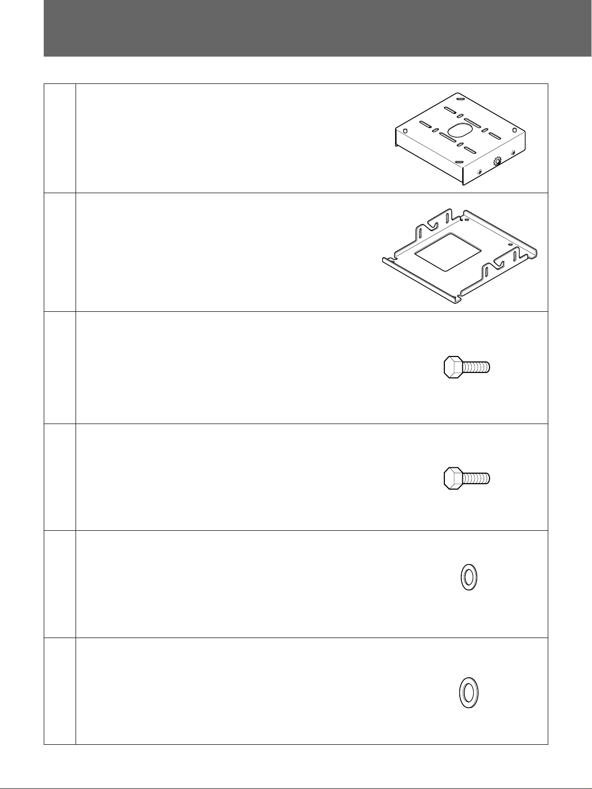
(a)
(b)
(c)
ベースボックス
Base box (1)
Socle (1)
Basisgehäuse (1)
Caja base (1)
Base (1)
サスペンションブラケット
Suspension bracket (1)
Support de suspension (1)
Aufhängehalterung (1)
Soporte de suspensión (1)
Staffa di sospensione (1)
ボルトM8×
Bolt M8 × 20 (2)
Boulon M8 × 20 (2)
Schraube M8 × 20 (2)
Perno M8 × 20 (2)
Bullone M8 × 20 (2)
(1)
20 (2)
(1)
部品番号/Parts number/
Numéro de pièce/
Teilenummer/
N´umero de componentes/
Numero dei componenti/
4-047-766-01
(d)
(e)
(f)
ボルトM6×
Bolt M6 × 12 (4)
Boulon M6 × 12 (4)
Schraube M6 × 12 (4)
Perno M6 × 12 (4)
Bullone M6 × 12 (4)
ワッシャーM8用
Washer M8 (2)
Rondelle M8 (2)
M8-Unterlegscheibe (2)
Arandela M8 (2)
Rondella M8 (2)
ワッシャーM6用
Washer M6 (4)
Rondelle M6 (4)
M6-Unterlegscheibe (4)
Arandela M6 (4)
Rondella M6 (4)
12 (4)
(2)
(4)
部品番号/Parts number/
Numéro de pièce/
Teilenummer/
N´umero de componentes/
Numero dei componenti/
4-056-754-01
部品番号/Parts number/
Numéro de pièce/
Teilenummer/
N´umero de componentes/
Numero dei componenti/
4-047-748-01
部品番号/Parts number/
Numéro de pièce/
Teilenummer/
N´umero de componentes/
Numero dei componenti/
4-056-755-01
6
Page 7
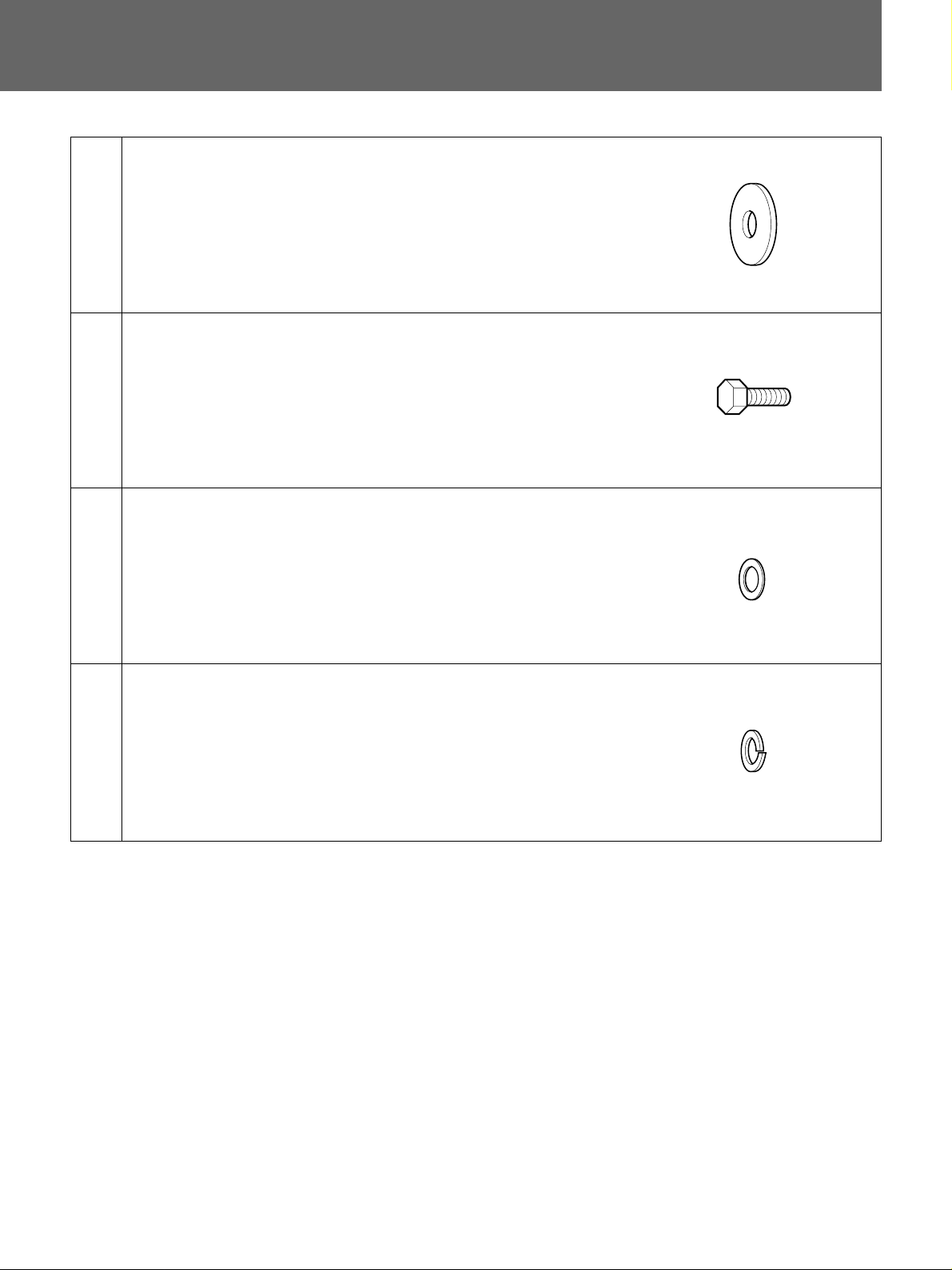
(g)
スペーサー(2)
Spacer (2)
Entretoise (2)
Abstandsring (2)
Espaciador (2)
Anello distanziatore (2)
部品番号/Parts number/
Numéro de pièce/
Teilenummer/
N´umero de componentes/
Numero dei componenti/
4-056-753-01
(h)
(i)
(j)
ボルトM10×25(4)
Bolt M10 × 25 (4)
Boulon M10 × 25 (4)
Schraube M10 × 25 (4)
Perno M10 × 25 (4)
Bullone M10 × 25 (4)
ワッシャーM10用 (4)
Washer M10 (4)
Rondelle M10 (4)
M10-Unterlegscheibe (4)
Arandela M10 (4)
Rondella M10 (4)
スプリングワッシャーM10用(4)
Spring washer M10 (4)
Rondelle élastique M10 (4)
M10-Federscheibe (4)
Arandela elástica M10 (4)
Rondella elastica M10 (4)
部品番号/Parts number/
Numéro de pièce/
Teilenummer/
N´umero de componentes/
Numero dei componenti/
4-068-372-01
部品番号/Parts number/
Numéro de pièce/
Teilenummer/
N´umero de componentes/
Numero dei componenti/
4-068-371-01
部品番号/Parts number/
Numéro de pièce/
Teilenummer/
N´umero de componentes/
Numero dei componenti/
4-068-373-01
7
Page 8

設置寸法/Installation Diagram/Schéma d’installation/
Installationsdiagramm/
スクリーンサイズと投射距離の寸法については、プロジェクター本体の取扱説明書または設置説明書をご覧ください。
For details of screen size and installation measurement for projection, refer to the Operating Manual or Installation
Manual for Dealers of the projector.
Pour plus de détails sur le format d’écran et la distance de projection, consultez le mode d’emploi du projecteur ou
le manuel d’installation destinéaux revendeurs du projecteur.
Genaue Angaben zu Projektionsschirmgröße und Installationsmaßen für die Projektion entnehmen Sie bitte der
Bedienungsanleitung oder der Installationsanleitung für Händler zum Projektor.
Para obtener información detallada sobre el tamaño de pantalla y las medidas de instalación para proyección,
consulte el manual de instrucciones del proyector o el manual de instalación para proveedores del proyector.
Per informazioni dettagliate sulla dimensione dello schermo e le misure di installazione del proiettore, fare
riferimento alle istruzioni per l’uso del proiettore o al manuale d’installazione per i rivenditori del proiettore.
8
Page 9
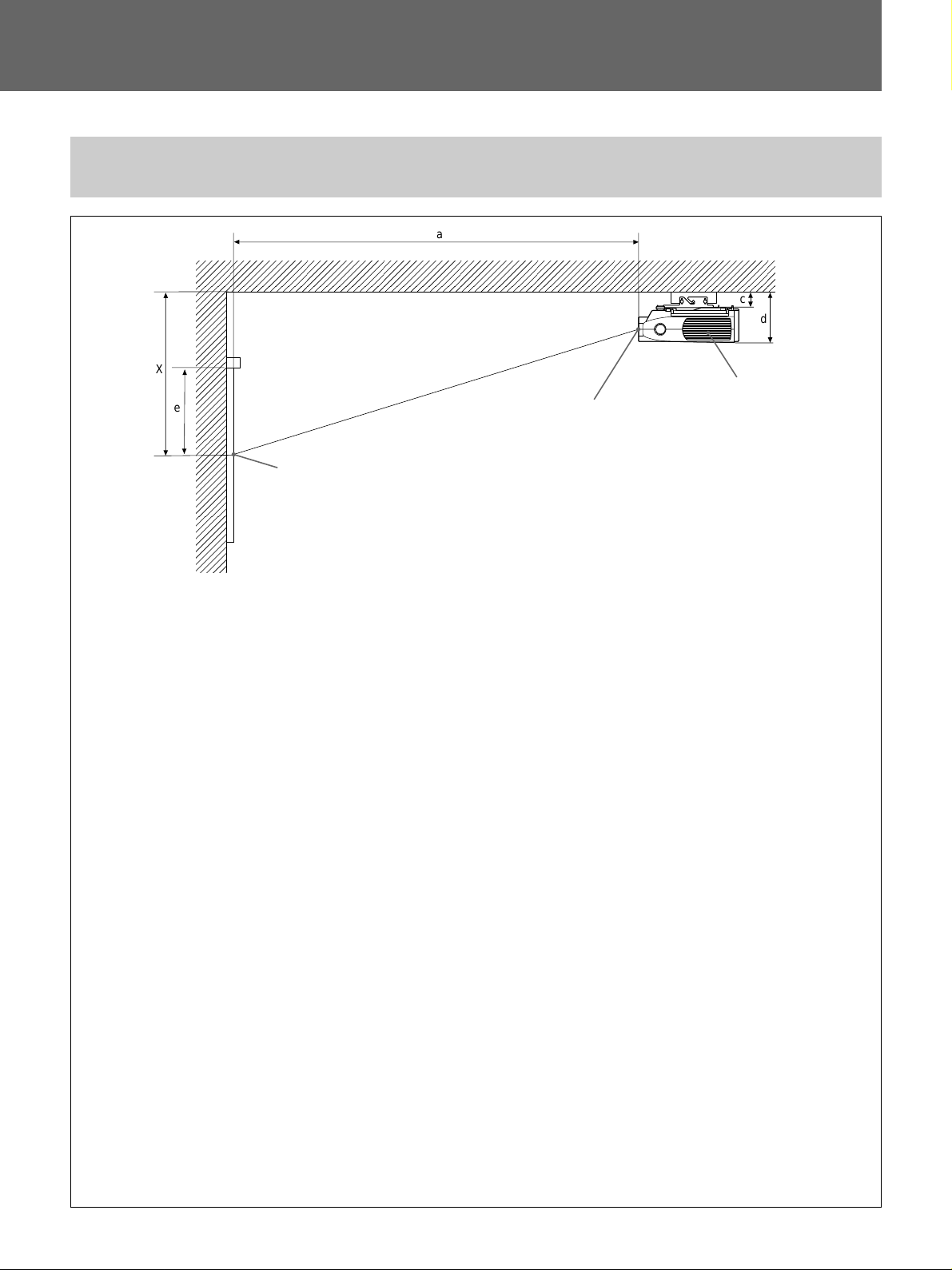
Diagrama de instalación/Schema dell’installazione/
横から見た図/Side view/Vue latérale/Seitenansicht/Vista lateral/Vista
laterale/
a
X
e
壁/
Wall/
Mur/
Wand/
Pared/
Muro/
a: レンズ中心からスクリーンまでの距離
Distance between the center of lens and the screen
Distance entre le centre de I’objectif et l’écran
Abstand zwischen der Mitte des Objektivs und dem Projektionsschirm
Distancia entre el centro del objetivo y la pantalla
Distanza fra il centro della lente e lo schermo
スクリーン中心/Center of
Screen/Centre de l’écran/
Mitte des Projektionsschirms/
Centro de la pantalla/Centro
dello schermo/
レンズ中心
Center of lens
Centre de I’objectif
Mitte des Objektivs
Centro del objetivo
Centro della lente
天井
Ceiling
Plafond
c
Decke
Techo
d
Soffitto
プロジェクター
Projector
Projecteur
Projektor
Proyector
Proiettore
c: 天井からサスペンションブラケット取付面までの距離:104.7mm
Distance between the ceiling and the mounting surface of the suspension bracket: 104.7 mm (4
Distance entre le plafond et le bas du projecteur: 104,7 mm (4
Abstand zwischen der Decke und der Montagefläche der Aufhängehalterung: 104,7 mm
Distancia entre el techo y la superficie de montaje del soporte de suspensión: 104,7 mm (4
Distanza dal soffitto alla superficie di montaggio della staffa di sospensione: 104,7 mm
d: 天井からプロジェクターの上面までの距離:330.3mm
Distance between the top of the projector and the ceiling: 330.3 mm ( 13inches)
Distance entre le dessus du projecteur et le plafond: 330,3 mm ( 13 pouces)
Abstand zwischen der Oberseite des Projektors und der Decke: 330,3 mm
Distancia entre la parte superior del proyector y el techo: 330,3 mm ( 13 pulgadas)
Distanza fra la parte superiore del proiettore ed il soffitto: 330,3 mm
e: スクリーン有効画面上端からスクリーン中心までの距離
Distance from the top edge of available projected picture to the center of screen
Distance entre le bord supérieur de l’image projetée disponible et le centre de l’écran
Abstand zwischen oberem Rand des verfügbaren projizierten Bildes und der Mitte des Projektionsschirms
Distancia desde el borde superior de la imagen proyectada disponible hasta el centro de la pantalla
Distanza dall’estremità superiore dell’immagine proiettata disponibile al centro dello schermo
x: 天井からスクリーンの中心までの距離
Distance between the ceilig and the center of the screen
Distance entre le plafond et le centre de l’écran
Abstand zwischen der Decke und der Mitte des Projektionsschirms
Distancia entre el techo y el centro de la pantalla
Distanza fra il soffitto e il centro dello schermo
1
/8 pouces)
1
/8 inches)
1
/8 pulgadas)
9
Page 10
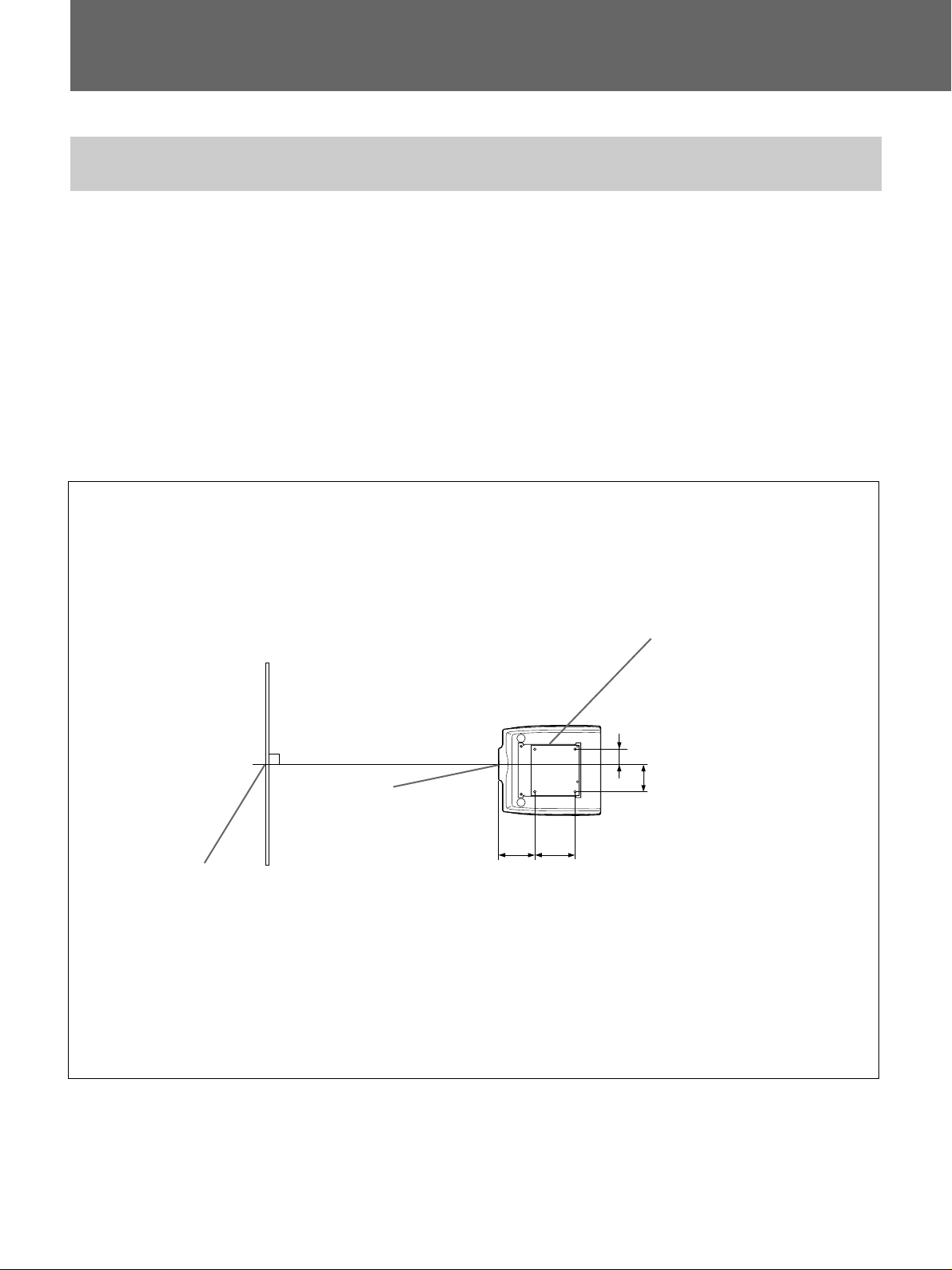
設置寸法/Installation Diagram/Schéma d’installation/
Installationsdiagramm/Diagrama de instalación/
上から見た図/Top view/Vue du dessus/Draufsicht/Vista superior/Vista
dall’alto/
プロジェクターのレンズの中心とスクリーンの中心が合うように設
置してく ださい。
Align the center of the lens with the center of the
screen.
Alignez le centre de l’objectif sur le centre de l’écran.
Richten Sie die Mitte des Objektivs an der Mitte des
Projektionsschirms aus.
Alinee el centro del objetivo con el centro de la
pantalla.
キャビネット前面
Front of the cabinet
Avant du meuble
Vorderseite des Gehäuses
Parte frontal de la caja
Parte anteriore
dell’apparecchio
Allineare il centro della lente con il centro dello
schermo.
ベースボックス
Base box
Socle
Basisgehäuse
Caja base
Base
スクリーン中心
Center of the Screen
Centre de l’écran
Mitte des Projektionsschirms
Centro de la pantalla
Centro dello schermo
レンズ中心
Center of lens
Centre de I’objectif
Mitte des Objektivs
Centro del objetivo
Centro della lente
227.1
15
(8
/16)
254
(10)
89 (3
1
/2)
1
165 (6
単位
Units : mm (inches)
Unité : mm (pouces)
Einheit : mm
Unidades : mm (pulgadas)
Unità : mm
/2)
: mm
10
Page 11
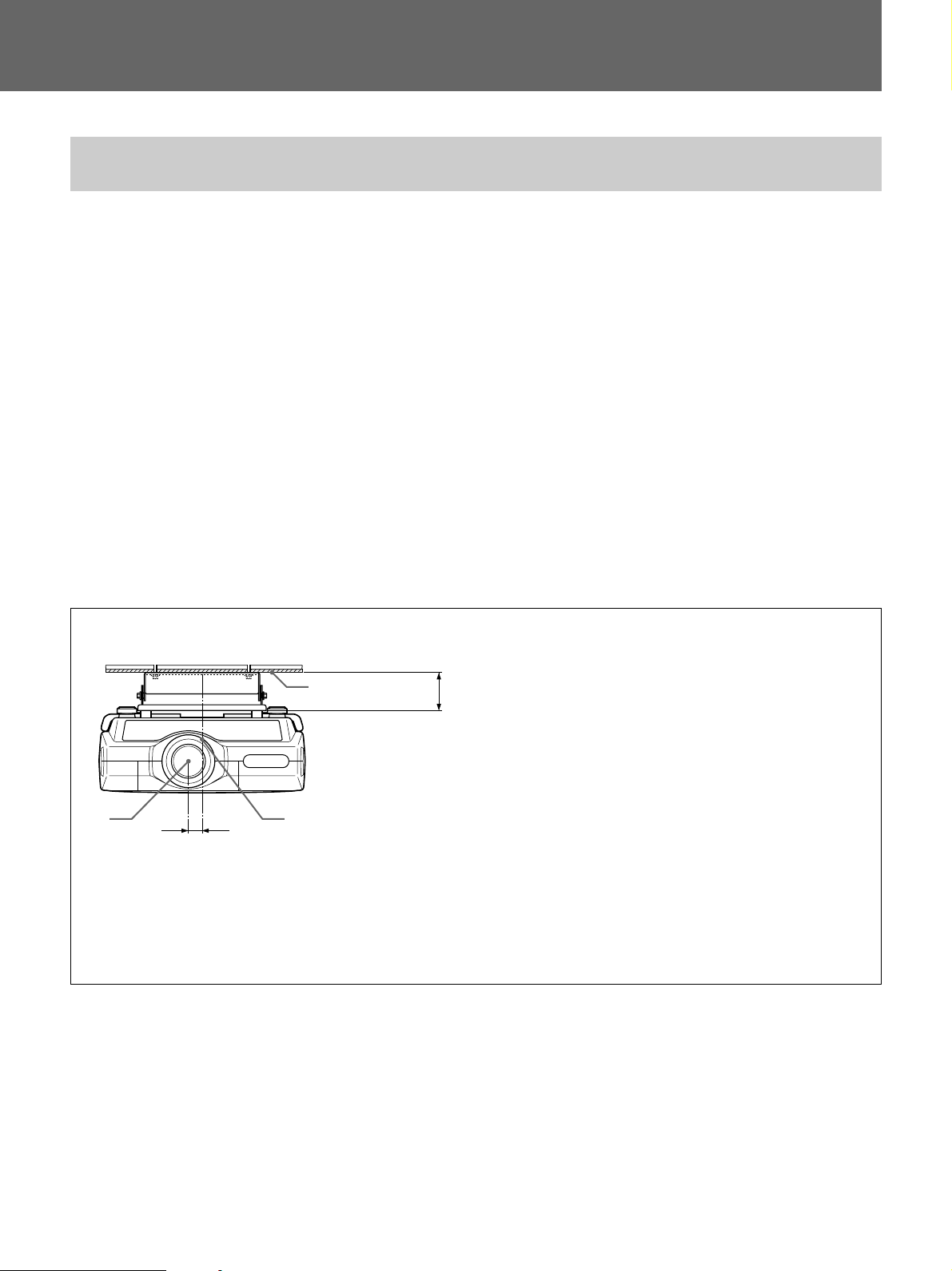
Schema dell’installazione/
前から見た図/Front view/Vue frontale/Vorderansicht/Vista frontal/Vista
frontale/
レンズの中心は、プロジェクターの中心より左側に38mmずれて
います。天井に設置するときは、プロジェクターの中心ではな くレ
ンズの中心と スクリーンの中心を合わせてください。
The lens is offset 38 mm (1 1/2 inches) to the left from
the center of the projector. When mounting, take care
to align the center of the lens with the center of the
screen; not the center of the projector.
L’objectif lentille est décalé de 38 mm (1
1
/2 pouces)
vers la gauche à partir du centre du projecteur. Lors
du montage, veillez à aligner correctement le centre
de l’objectif sur le centre de l’écran; pas le centre du
projecteur.
El objetivo está desplazado 38 mm (1
la izquierda del centro del proyector. Al realizar el
montaje, alinee el centro del objetivo con el centro de
la pantalla y no con el centro del proyector.
La lente del proiettore è spostata di 38 mm a sinistra
rispetto al centro del proiettore. Durante il montaggio,
assicurarsi di allineare il centro della lente al centro
dello schermo e non al centro del proiettore.
1
/2 pulgadas) a
Das Objektiv ist gegenüber der Mitte des Projektors
um 38 mm nach links versetzt. Achten Sie beim
Installieren darauf, die Mitte des Objektivs, nicht die
Mitte des Projektors, an der Mitte des
Projektionsschirms auszurichten.
1
32
38 mm
(1 1/2 inches)
(1 1/2 pouces)
(1 1/2 pulgadas)
c: 天井からサスペンションブラケット取り付け面までの距離:104.7 mm /
Distance between the ceiling and the mounting surface of the
suspension bracket: 104.7 mm (4 1/8 inches)/Distance entre le
c
plafond et la surface de montage du support de suspension:
104,7mm (4
Montageoberfläche der Aufhängehalterung: 104,7 mm/Distancia
entre el techo y la superficie de montaje del soporte de
suspensión: 104,7 mm (4 1/8 pulgadas)/Distanza fra il soffitto e
la superficie di montaggio della staffa di sospensione: 104,7
mm.
天井/Ceiling/Plafond/Decke/Techo/Soffitto/
1
プロジェクターの中心/Center of projector/Centre du
2
projecteur/Mitte des Projektors/Centro del proyector/
Centro del proiettore/
レンズの中心/Center of lens/Centre de l’objectif/Mitte des
3
Objektivs/Centro del objetivo/Centro della lente/
1
/8 pouces)/Abstand zwischen der Decke und der
11
Page 12
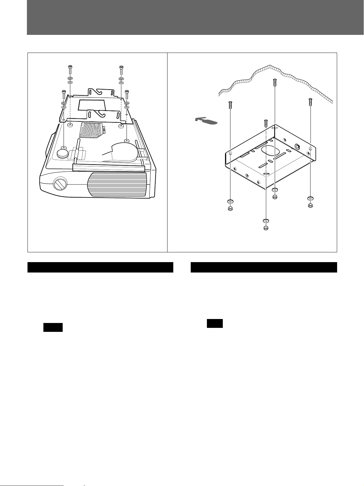
天井への取り付けかた/Attaching to the Ceiling/
Montage au plafond/Montage an der Decke/
1
(h)
(j)
(i)
(h)
(j)
(i)
(b)
プロジェクター底面
Bottom of projector
Base du projecteur
Unterseite des Projektors
Base del proyector
Base del proiettore
(h)
(j)
(i)
(h)
(j)
(i)
2
スクリーン方向
Screen forward
Ecran
Projektionsschirm
Pantalla
Direzione dello
schermo
(a)
日本語
1 プロ ジェク タ ー を裏返し、サスペンションブラケ ット(b)を取
り付ける。
ボルトM10×25(h)、スプリ ングワッシャーM10用(j)、ワッ
シャーM10用(i)を使用します。
ご注意
取り付けの際に、ボル トをきつく締めすぎないよう に注意
してください。
2 ベースボックス(a)を天井に取 り付ける 。
市販のM10ボルト、ナッ ト、ワッシャーをご使用ください。
English
1 Turn the projector upside down and attach the
suspension bracket (b).
Use M10 × 25 bolts (h), M10 spring washers (j) and
M10 washers (i).
Note
When attaching the bracket, be careful not to
overtighten the bolts.
2 Attach the base box (a) to the ceiling.
Use M10 bolts, nuts and washers (not supplied).
12
Page 13
Montaje en el techo/Montaggio al soffitto/
Français
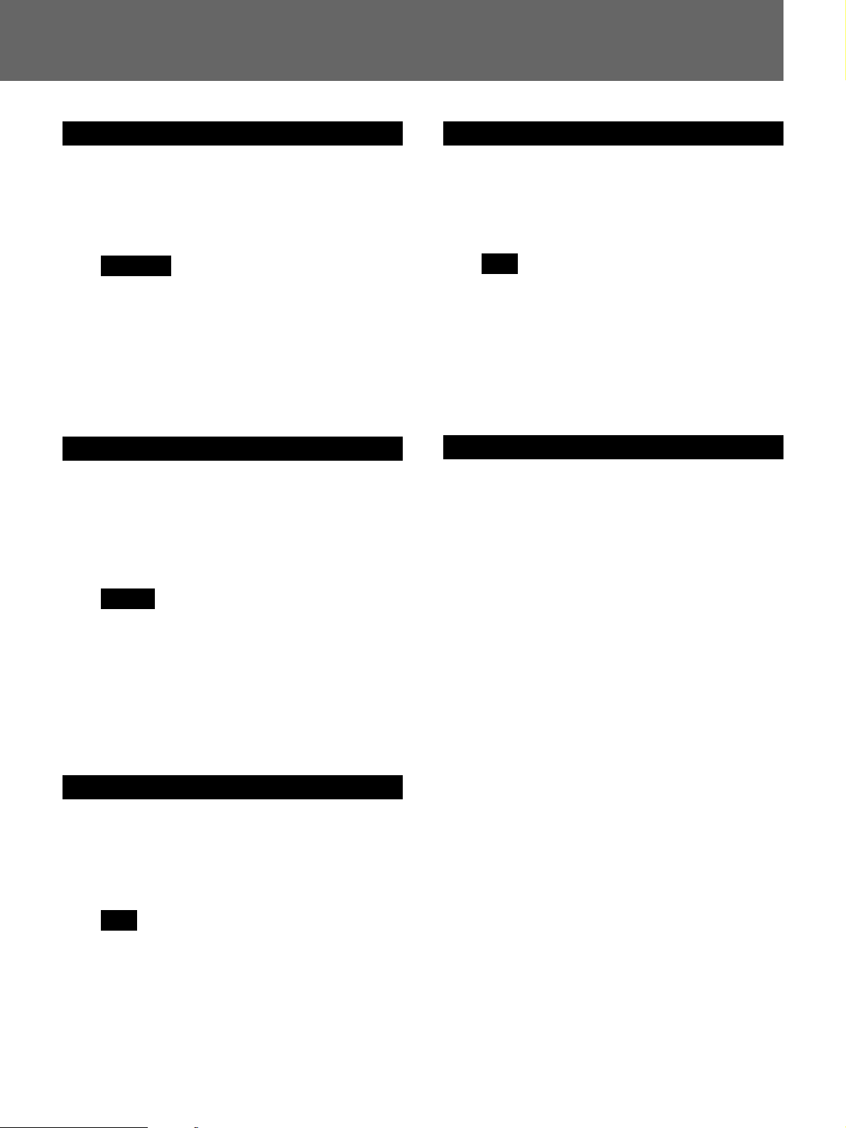
1 Retournez le projecteur et fixez le support de
suspension (b).
Utilisez les boulons M10 × 25 (h), les rondelles
élastiques M10 (j) et les rondelles M10 (i).
Remarque
Lors de la fixation du support, ne serrez pas trop les
écrous.
2 Fixez le socle (a) au plafond.
Utilisez les boulons M10, les écrous et les rondelles
(non fournies).
Deutsch
1 Legen Sie den Projektor auf den Kopf, und bringen
Sie die Aufhängehalterung (b) an.
Verwenden Sie dazu die Schrauben M10 × 25 (h), die
M10-Federscheiben (j) und die M10-Unterlegscheiben
(i).
Hinweis
Achten Sie beim Anbringen der Halterung darauf, die
Schrauben nicht zu stark anzuziehen.
Italiano
1 Capovolgere il proiettore e fissare la staffa di
sospensione (b).
Utilizzare bulloni M10 × 25 (h), rondelle elastiche M10
(j) e rondelle M10 (i).
Nota
Durante l’installazione della staffa, assicurarsi di non
serrare eccessivamente i bulloni.
2 Fissare la base (a) al soffitto.
Utilizzare bulloni M10, dadi e rondelle (non in
dotazione).
中文
2 Bringen Sie das Basisgehäuse (a) an der Decke an.
Verwenden Sie dazu M10-Schrauben, -Muttern und Unterlegscheiben (nicht mitgeliefert).
Español
1 Dele la vuelta al proyector y fije el soporte de
suspensión (b).
Emplee los pernos M10 × 25 (h), las arandelas
elásticas M10 (j) y las arandelas M10 (i).
Nota
Al fijar el soporte, asegúrese de no apretar
excesivamente los pernos.
2 Fije la caja base (a) al techo.
Emplee los pernos M10, tuercas y arandelas (no
suministradas).
13
Page 14
天井への取り付けかた/Attaching to the ceiling/Montage au plafond/
Montage an der Decke/Montaje en el techo/Montaggio al soffitto/
3
(c)
(e)
(g)
(a)
(g)
(b)
(e)
(c)
4
(d)
(d)
(a)
(f)
(f)
(d)
(f)
(d)
(f)
(b)
日本語
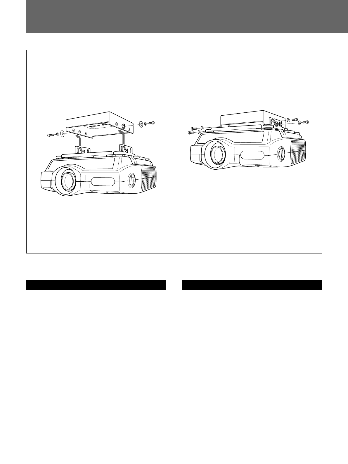
3 ボルトM8×20(c)2本を、ワッシャー(e)、スペーサー(g)
の順に通しベースボックス(a)のヒ ンジ部に仮止めする。
ベースボックスのヒンジ部に、 サスペンシ ョ ンブラケ ット(b)
を引っかけプロジェクターを吊るす。
4 ボルトM6×12(d)4本とワッシャーM6(f)を取り付けて、
プロ ジ ェ クターのスクリ ー ン角度を合わせる。角度調整後、
ボルトM6×12(d)4本すべてと手順3で仮止めしたボル
トM8×20(c)2本をしっかり締めて固定する。
5 固定後にプロジェクター本体のレンズシフト機能 を用いて
画像とスクリーンの位置を調整する。
14
English
3 Tighten loosely two bolts M8 × 20 (c), washers (e)
and spacers (g) to the base box hinge pins (a). Hang
the projector with the suspension bracket (b) on the
base box hinge pins (two bolts M8 × 20 (c)).
4 Attach four bolts M6 × 12 (d) and washers M6 (f),
tighten all bolts M6 × 12 (d) (angle holding) and two
bolts M8 × 20 (c) (attached in step 3) to secure the
projector to the screen angle.
5 After having secured the projector, adjust the
position of the screen and projected image using
SHIFT function of the projector.
Page 15
Français
Español
3 Serrez légèrement les deux boulons M8 × 20 (c), les
rondelles (e) et les entretoises (g) aux goupilles du
socle (a). Accrochez le projecteur aux goupilles du
socle (deux boulons M8 × 20 (c)) au moyen du
support de suspension (b).
4 Fixez les quatre boulons M6 × 12 (d) et les rondelles
M6 (f), serrez tous les boulons M6 × 12 (d)
(maintien angulaire) et les deux boulons M8 × 20 (c)
(fixés à l’étape 3) pour fixer le projecteur selon
l’angle de l’écran.
5 After having secured the projector, adjust the
position of the screen and projected image using
SHIFT function of the projector.
Deutsch
3 Bringen Sie zwei Schrauben M8 × 20 (c),
Unterlegscheiben (e) und Abstandsringe (g) an den
beiden Scharnierstiften des Basisgehäuses (a) an.
Drehen Sie diese Schrauben zunächst nicht ganz
fest. Hängen Sie den Projektor mit der
Aufhängehalterung (b) in die Scharnierstifte am
Basisgehäuse ein (zwei Schrauben M8 × 20 (c)).
4 Bringen Sie vier Schrauben M6 × 12 (d) und M6-
Unterlegscheiben (f) an. Ziehen Sie alle Schrauben
M6 × 12 (d) (Winkelhalterung) und die beiden in
Schritt 3 angebrachten Schrauben M8 × 20 (c) fest,
und sichern Sie damit den Projektor im richtigen
Winkel zum Projektionsschirm.
3 Fije dos pernos M8 × 20 (c), las arandelas (e) y los
espaciadores (g) a los pasadores de bisagra de la caja
base (a). Cuelgue el soporte de suspensión del
proyector (b) en los pasadores de bisagra de la caja
base (dos pernos M8 × 20 (c)).
4 Fije cuatro pernos M6 × 12 (d) y las arandelas M6
(f). A continuación, apriete todos los pernos
M6 × 12 (d) (sujeción en ángulo) y los dos pernos
M8 × 20 (c) (insertados en el paso 3) para asegurar
el proyector al ángulo de la pantalla.
5 Una vez fijado el proyector, ajuste la posición de la
pantalla y la imagen proyectada mediante la función
SHIFT del proyector.
Italiano
3 Applicare due bulloni M8 × 20 (c), rondelle (e) e
distanziatori (g) ai piedini della cerniera della base
(a). Applicare il proiettore con la staffa di
sospensione (b) ai piedini della cerniera della base
(due bulloni M8 × 20 (c)).
4 Applicare quattro bulloni M6 × 12 (d) e rondelle M6
(f), serrare tutti i bulloni M6 × 12 (d) (staffa ad
angolo) e due bulloni M8 × 20 (c) (applicati al punto
3) per fissare il proiettore all’angolo dello schermo.
5 Dopo aver fissato il proiettore, regolare la posizione
dello schermo e dell’immagine proiettata usando la
funzione SHIFT del proiettore.
5 Nach dem Sichern des Projektors stellen Sie mit der
Funktion SHIFT des Projektors die Position von
Projektionsschirm und projiziertem Bild ein.
中文
15
Page 16
天井への取り付け例/Installation Examples/Exemples
d’installation au plafond/Installationsbeispiele/
以下はサスペンションサポートが天 井に取り付けられたときの様子
を示します。天井の材質によって補強方法は多少異なります。
ご注意
取り付ける前に天井の 最大耐用 荷重が250kg以上あることをお確
かめください。
The following illustrations show the projector
suspension support attached to with the ceiling.
Installation is different depending on the material of
ceiling.
Caution
Before installation, check that the maximum ceiling
loading is in excess of 250 kg (551 lb 2 oz).
Les illustrations suivantes représentent le support de
suspension du projecteur fixé au plafond.
L’installation s’effectue différemment en fonction de
la constitution du plafond.
Remarque
Vérifiezque la charge maximale du plafond soit
suérieure à 250 kg (551 lb 2 on) avant l’installation.
Las siguientes ilustraciones muestran el soporte de
suspensión para proyector fijado al techo. La
instalación varía en función del material del techo.
Nota
Compruebe la capacidad de carga máxima del techo
sea superior a 250 kg (551 lb 2 oz) antes de realizar la
instalación.
Le seguenti illustrazioni mostrano il montaggio al
soffitto del supporto di sospensione del proiettore. La
procedura di installazione varia a seconda del tipo di
soffitto.
Attenzione
Prima di procedere con l’installazione, verificare che
il peso massimo di portata del soffitto sia superiore a
250 kg.
In den Abbildungen unten ist dargestellt, wie die
Projektoraufhängung an der Decke angebracht wird.
Die Installation unterscheidet sich je nach Material
der Decke.
Hinweis
Überprüfen Sie vor der Installation, ob die maximale
Belastbarkeit der Decke mindestens 250 kg beträgt.
16
Page 17
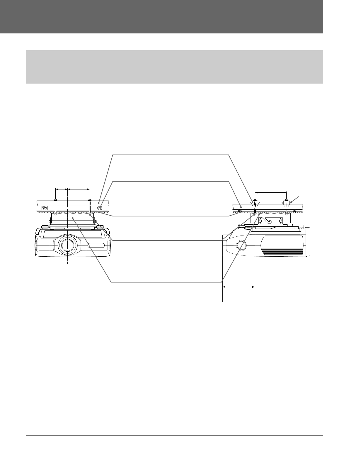
Ejemplos de instalación en el techo/Esempi di
installazione al soffitto/
板天井に取り付ける場合/For wooden ceiling/Pour un plancher/Montage an
einer Holzdecke/Para techos de madera/Montaggio ad un soffitto in legno/
平屋または最上階の場合/For-one-story house or uppermost floor/Pour maison à un étage ou plafond
sous un toit/Decke eines einstöckigen Hauses oder des obersten Stockwerks/ Para casas de una
planta o plantas superiores/Montaggio in una casa a piano unico o all’ultimo piano/
くぎ
Nail
Clou
Nagel
Punta
Chiodo
(3
89
補強材/Reinforcing material/Matériel de
renfort/Verstärkungsmaterial/Material de
165
1
/2)
(6 1/2)
refuerzo/Materiale di rinforzo/
梁
(5×20 cm)
Poutre de toit/Dachträgerbalken (ca. 5 x
20 cm) /Viga de techo (2” x 8”) /Trave del
soffitto (circa 5 x 20 cm.) /
/Roof beam (2” x 8”) /
254
(10)
レンズ中心
Center of lens
Centre de I’objectif
Mitte des Objektivs
Centro del objetivo
Centro della lente
単位
: mm
Units : mm (inches)
Unité : mm (pouces)
Einheit : mm
Unidades : mm (pulgadas)
Unità : mm
天井/Ceiling line/Niveau du plafond/
Deckenlinie/Línea de techo/Livello del
soffitto/
ナットとワッシャーで締めた
M10 bolt with nut and washer/Boulon
M10 avec écrou et rondelle/M10Schraube mit Mutter und/Perno M10 con
tuerca y arandela/Bullone M10 con dado
e rondella/
ベースボックス
Base box
Socle
Basisgehäuse
Caja base
Base
M10
ボルト/
キャビネット前面
Front of the cabinet
Avant du meuble
Vorderseite des Gehäuses
Parte frontal de la caja
Parte anteriore
dell’apparecchio
227.1
15
(8
/16)
17
Page 18
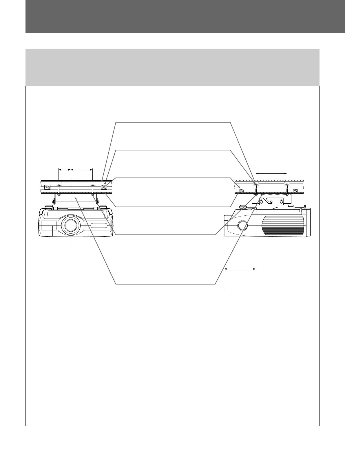
天井への取り付け例/Installation Examples/Exemples d’installation au
plafond/Installationsbeispiele/
その他の階の場合/For other floors/Autres sols/Zwischendecken/Para otros
suelos/Per altri piani/
上の階の床/Floor line/Niveau du plancher/
Stockwerkslinie/Línea de suelo/Livello del
pavimento/
165
89
1
(3
レンズ中心
Center of lens
Centre de I’objectif
Mitte des Objektivs
Centro del objetivo
Centro della lente
/2)
(6
1
/2)
梁/Joist (2” x 8”)/Traverse/Deckenbalken(ca.
5 x 20 cm)/Viga(2” x 8”)/Travetto(circa 5 x 20
cm.)/
梁
(5×20 cm)
(2” x 8”) /Dachträgerbalken (ca. 5 x 20 cm) /
Viga de techo (2” x 8”) /Trave del soffitto (circa
5 x 20 cm.) /
天井/Ceiling line/Niveau du plafond/
Deckenlinie/Línea de techo/Livello del
soffitto/
ナットとワッシャーで締めた
M10 bolt with nut and washer/Boulon
M10 avec écrou et rondelle/M10Schraube mit Mutter und
Unterlegscheibe/Perno M10 con tuerca y
arandela/Bullone M10 con dado e
rondella/
ベースボックス
Base box
Socle
Basisgehäuse
Caja base
Base
/Roof beam (2” x 8”) /Traverse
ボルト
M10
/
キャビネット前面
Front of the cabinet
Avant du meuble
Vorderseite des Gehäuses
Parte frontal de la caja
Parte anteriore
dell’apparecchio
227.1
15
(8
254
(10)
/16)
単位
: mm
Units : mm (inches)
Unité : mm (pouces)
Einheit : mm
Unidades : mm (pulgadas)
Unità : mm
18
Page 19
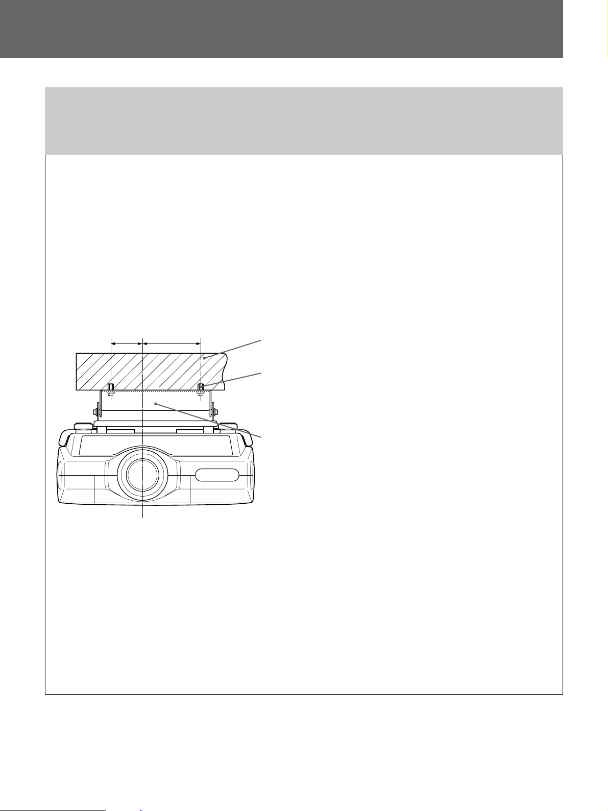
Ejemplos de instalación en el techo/Esempi di installazione al
soffitto/
コンクリート天井に取り付ける場合/For concrete celing/Pour un plafond en
béton/Betondecke/Para techos de hormigón/Montaggio ad un soffitto di
cemento/
壁端から100mm以上距離をとってください。
Place bolts at least 100 mm (4 inches) away
from wall. /Ecartez les boulons de 100 mm
(4 pouces) du mur minimum. /Schrauben
mindestens 100 mm von der Wand entfernt
anbringen. /Coloque los pernos a una
distancia de al menos 100 mm (4 pulgadas)
de la pared. /Collocare i bulloni ad almeno
100 mm dal muro. /
89
1
/2)
(3
レンズ中心
Center of lens
Centre de I’objectif
Mitte des Objektivs
Centro del objetivo
Centro della lente
165
(6 1/2)
コンクリート天井/Concrete ceiling/Plafond en béton/Betondecke/
Techo de hormigón/Soffitto di cemento/
コンクリートアンカー
mm; 13/32 inch dia.) / Ancrage pour béton (supérieur à 10 mm; 13/32
pouce de diamètre) /Betonanker (mehr als 10 mm Durchmesser)
/Anclaje para hormigón (con diámetro superior a 10 mm; 13/32
pulgada) /Catena per cemento (oltre 10 mm di diametro)/
ベースボックス
Base box
Socle
Basisgehäuse
Caja base
Base
(10 mm
径以上
/Anchor for concrete (over 10
)
19
Page 20
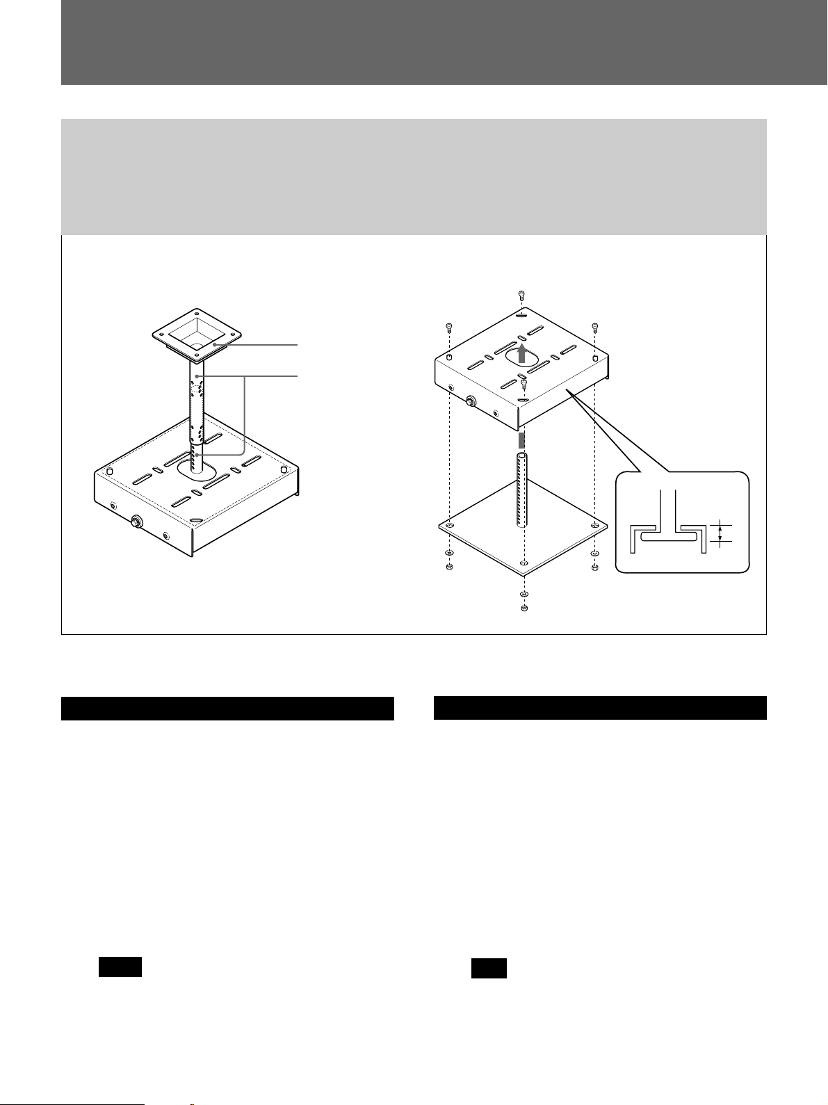
天井への取り付け例/Installation Examples/Exemples d’installation au
plafond/Installationsbeispiele/
PSS-10を併用する場合/Using PSS-2000 and PSS-10/Utilisation du PSS-2000 et
du PSS-10/Die PSS-2000 und die PSS-10/Empleo de las unidades PSS-2000
y PSS-10/Uso dei componenti PSS-2000 e PSS-10/
(a)
PSS-10
2
(a)
1
3
(a)
PSS-10
(A)
日本語
1 PSS-10の上側のサポートを天井に取 り付ける 。
(PSS-10の取付説明書をご覧ください。)
2 PSS-10の下側のサポートをベースボッ クスの穴に下か ら 通
し、PSS-10に付属のM10ボルト、ワッシャーM10用、M10
ナッ トで固定する。
3 支柱が希望の長さになるように調整してから、上下のサ
ポートを固定する。
(PSS-10の取付説明書をご覧ください。)
ご注意
PSS-2000とPSS-10の取り付けは、PSS-10の下側をPSS2000のブラケットに通すため ブラケッ トの板厚分5.5mm
(A)がPSS-10の取付寸法の調整数値からマイナスになり
ます。
20
English
1 Attach the upper part of the PSS-10 to the ceiling.
(See the PSS-10 installation manual for details.)
2 Insert the lower part of the PSS-10 into the hole in the
base box and secure them using the M10 bolts, M10
washers, and M10 nuts supplied with the PSS-10.
3 Adjust the length and secure the upper and lower
parts of the PSS-10.
(See the PSS-10 installation manual for details.)
Note
The distance between the projector and the ceiling
will be decreased by 5.5 mm (7/32 inch) (A) from the
installation measurements of the PSS-10 when the
PSS-2000 and the PSS-10 are used together.
Page 21

Ejemplos de instalación en el techo/Esempi di installazione al
soffitto/
Français
1 Fixez la partie supérieure du PSS-10 au plafond. (Voir
le manuel d’installation PSS-10 pour plus de détails.)
2 Insérez la partie inférieure du PSS-10 dans l’orifice du
socle et fixez-la à l’aide des écrous M10, des rondelles
M10 et des écrous M10 fournis avec le PSS-10.
3 Réglez la longueur et fixez les parties supérieure et
inférieure du PSS-10.
(Voir le manuel d’installation PSS-10 pour plus de détails.)
Remarque
La distance entre le projecteur et le plafond diminue de
5,5 mm (
d’installation du PSS-10 lorsque le PSSPSS-10 sont utilisés conjointement.
7
/32 pouce) (A) à partir des mesures
2000 et le
Deutsch
1 Bringen Sie den oberen Teil der PSS-10 an der Decke
an. Einzelheiten dazu finden Sie in der
Installationsanleitung zur PSS-10.
2 Fügen Sie den unteren Teil der PSS-10 in die
Aussparung des Basisgehäuses ein, und sichern Sie die
Teile mit den M10-Schrauben, M10-Unterlegscheiben
und M10-Muttern, die mit der PSS-10 geliefert werden.
Italiano
1 Fissare la parte superiore del PSS-10 al soffitto.
(Per i dettagli, consultare il manuale d’installazione del
PSS-10).
2 Inserire la parte inferiore del PSS-10 nel foro situato
nella base e fissare entrambe le parti mediante i bulloni
M10, le rondelle M10 e i dadi M10 in dotazione con il
PSS-10.
3 Regolare la lunghezza e fissare le parti superiore ed
inferiore del PSS-10. (Per i dettagli, consultare il
manuale d’installazione del PSS-10).
Nota
La distanza fra il proiettore ed il soffitto verrà
diminuita di 5,5
indicate per l’installazione del PSS-10 qualora il PSS-
2000 e il PSS-10 siano utilizzati insieme.
中文
(A) mm rispetto alle misurazioni
3 Stellen Sie die gewünschte Länge ein, und sichern Sie
den unteren und oberen Teil der PSS-10.
(Einzelheiten dazu finden Sie in der
Bedienungsanleitung zur PSS-10.)
Hinweis
Der Abstand zwischen der Decke und dem Projektor
verringert sich gegenüber den Installationsmaßen für die
PSS-10 um 5,5 mm (A), wenn die PSS10 zusammen benutzt werden.
2000 und die PSS-
Español
1 Fije la parte superior del PSS-10 al techo.
(Para obtener más información, consulte el manual de
instalación del PSS-10.)
2 I
nserte la parte inferior del PSS-10 en el orificio de la
caja base y bloquéelos con los pernos M10, las arandelas
M10 y las tuercas M10 suministrados con el PSS-10.
3 Ajuste la longitud y asegure las partes superior e
inferior del PSS-10.
(Para obtener más información, consulte el manual de
instalación del PSS-10.)
Nota
La distancia entre el proyector y el techo disminuirá en
5,5 mm (
de instalación del PSS-10 si utiliza conjuntamente las
unidades PSS-
7
/32 pulgada) (A) con respecto a las medidas
2000 y PSS-10.
21
Page 22
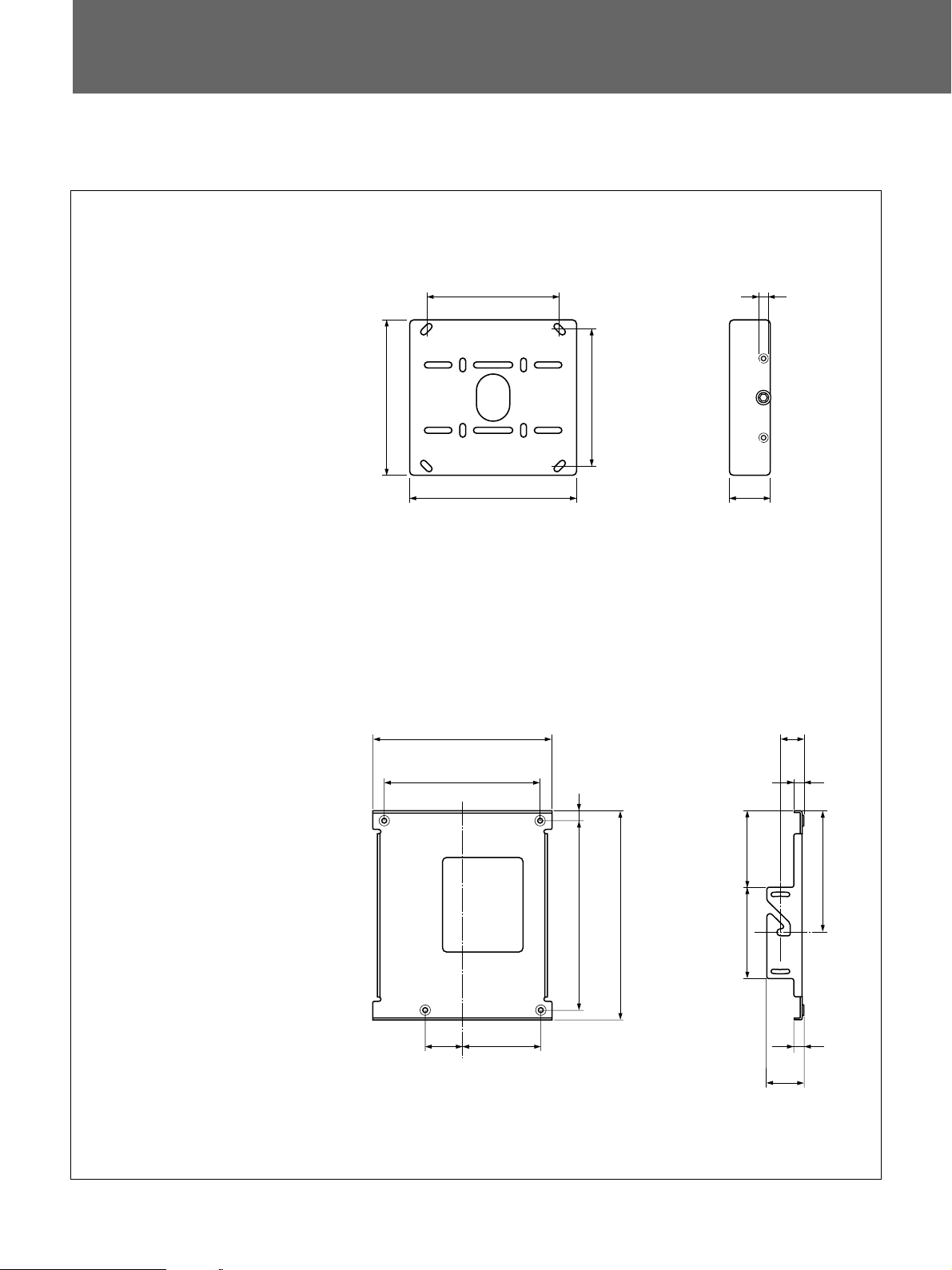
主な仕様/Specifications/Spécifications/Technische
Daten/Especificaciones/Caratteristiche tecniche/
最大外形寸法/Dimensions/Mesures/Abmessungen/Dimensiones/Dimensioni/
ベースボックス
Base box
Socle
Basisgehäuse
Caja base
Base
サスペンションブラケット
Suspension bracket
Support de suspension
Aufhängehalterung
Soporte de suspensión
Staffa di sospensione
(a)
3
298.4
(b)
)
4
/
(11
(13
(11
350
25
304
31
254
(10)
320.7
(12
/32)
/32)
15.9
5
/8)
(
254
(10)
5
/8)
76.2
(3)
44.4
(1 3/4)
17.9
23
/32)
(1)
25.5
(
単位
: mm
Units : mm (inches)
Unité : mm (pouces)
Einheit : mm
Unidades : mm (pulgadas)
Unità : mm
22
(2
72
27
/32)
152
(5 31/32)
)
16
/
3
360 (14
)
16
/
3
411 (16
)
16
/
15
150.6
(5
177.8 (7)
69.8
3
(2
/4)
7
17.9
23
(
)
16
/
239.5 (9
/32)
Page 23

質量 約5.5kg
耐用荷重 最大50kg
仕様および外観は、改良のため予告なく変更することがありますが、ご了承ください。
Mass : Approx. 5.5 kg (12 lb 2 oz)
Loading: Maximum 50 kg (110 lb 4 oz)
Design and specifications are subject to change without notice.
Poids : 5.5 kg approx. (12 lb 2 on)
Charge: 50 kg max. (110 lb 4 on)
La conception et les spécifications sont sujettes à modifications sans préavis.
Gewicht : ca. 5.5 kg
Belastbarkeit: max 50 kg
Änderungen, die dem technischen Fortschritt dienen, bleiben vorbehalten.
Masa: 5.5 kg aprox. (12 lb 2 oz)
Carga: 50 kg máximo (110 lb 4 oz)
Diseño y especificaciones sujetos a cambios sin previo aviso.
Peso: 5.5 kg approssimativo
Carico: 50 kg massimo
Il design e le caratteristiche tecniche sono soggetti a modifiche senza preavviso.
23
Page 24

お問い合わせは
「ソニー業務用製品ご相談窓口のご案内」
ソニー株式会社
ソニーマーケティング株式会社情報システム営業本部
〒
141-0001
〒
108-0074
Printed in U.S.A.
にある窓口へ
東京都品川区北品川6-7-35
東京都港区高輪4-10-18
 Loading...