

Page 1
Color Video
Projector
3-865-080-11(1)
Installation Manual for Dealers
CAUTION
THIS INSTALLATION MANUAL IS FOR USE BY QUALIFIED PERSONNEL
ONLY.
GB
VPH-V20M/V20U
VPH-V22M
1998 by Sony Corporation
Page 2

English
Before Installing
Table of Contents
Installation
Before Installing ................................................................ 3
Projector Dimensions .............................................................. 3
Installation Procedures ............................................................ 6
Installation Diagrams ........................................................ 8
Floor Installation Using Front Projection Flat Screen ............8
Ceiling Installation Using Front Projection Flat Screen .........9
When the Screen Size is Not Described in the Diagrams .....10
Floor Installation Using Rear Projection Screen...................11
Ceiling Installation Using Rear Projection Screen ...............12
Level Projection, Floor Installation ...................................... 13
Level Projection, Ceiling Installation ................................... 14
Modifications of Parts ..................................................... 15
Adjustment
Opening the Top Panel .......................................................... 15
Removing the Cabinet........................................................... 16
Detaching the Lens Block .....................................................18
Changing the CRT Spacer.....................................................19
Adjusting the Lens Spacer for 150- to 250-inch
Projection ..............................................................................23
Changing the Polarity............................................................24
Lens Focus Adjustment .................................................. 25
Preparation ............................................................................ 25
Adjusting the Lens Focus...................................................... 26
Registration Adjustment ................................................. 27
Preparations ........................................................................... 28
Adjusting the Red Registration .............................................28
Adjusting Blue Registration .................................................. 29
When the Registration Adjustment is Complete ................... 29
2 Installation
Table of contents
Page 3
Before Installing
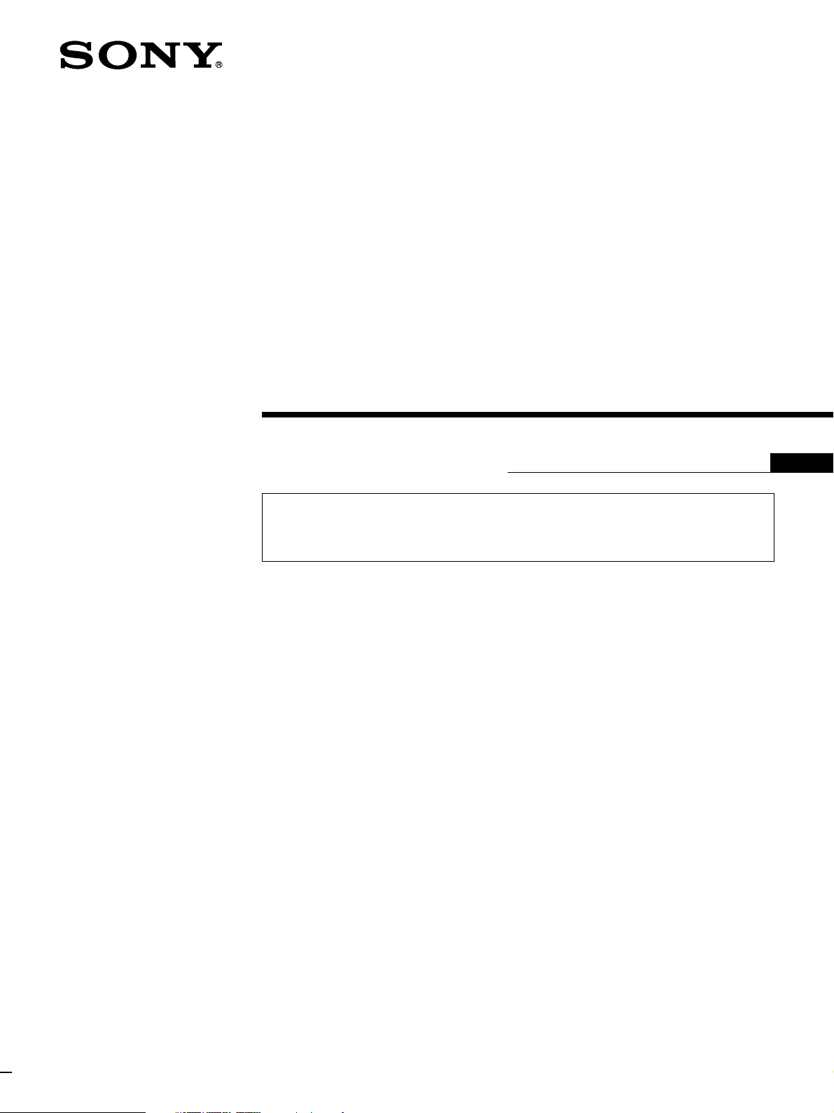
Projector Dimensions
Side
Center of the green lens
/8)
3
186.5 (7
28.5 (1 1/8)
/2)
1
87.5 (3
3
)
/2
1
239 (9
/8)
288.5 (11
Front
Rear
19.5 (25/32)
/2)
1
86 (3
60 (2 3/8) 60 (2 3/8)
597.5 (23 5/8)
302 (12)
59 (2 3/8)
/32)
21
16 (
578 (22
/4)
3
154.5
(5
7
/8)
150 (6)
Unit: mm (inches)
Unit: mm (inches)
GB
English
25 (1)
340 (13 1/2) 25 (1)
533 (21)
/32)
21
16 (
Unit: mm (inches)
Installation 3
Page 4
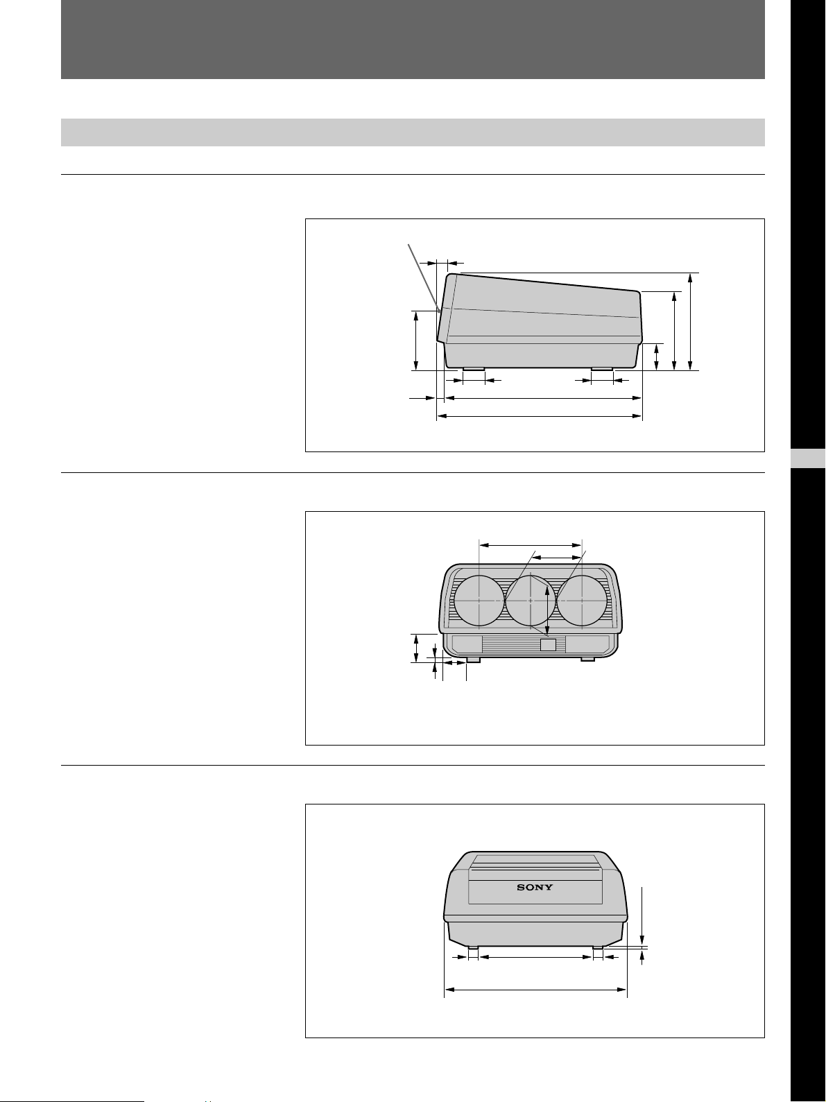
Before Installing
Top
533 (21)
/8)
7
72(2
/2)
1
189 (7
/8)
5
598 (23
Unit: mm (inches)
Illumination
To obtain a clear picture, the screen should not be exposed to illumination
or sunlight directly from the front.
• Ceiling mounted spot lighting is recommended. Use a construction over
light scattering illumination such as fluorescent lamps.
• Cover the windows that face the screen with opaque draperies.
• It is desirable to install the projector in a room whose floor and walls are
of reflecting material, it would be desirable to change to a dark carpet and
wall paper.
Caution
Take care not to touch portions of the projector other than those indicated
in this manual because dangerous high voltages are present. To change the
polarity, first turn the MAIN POWER switch off.
4 Installation
Page 5
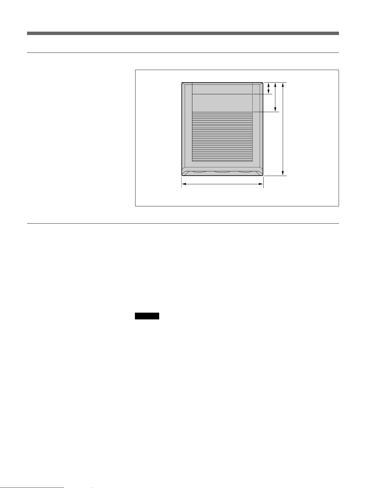
Necessary Clearance for Maintenance
When you install the projector, be sure to provide the clearance around it
as shown for maintenance service.
/8)
7
630 (24
R569 (22 1/2)*
150 (6)
730 (28 3/4)
*R:Radius
Unit: mm (inches)
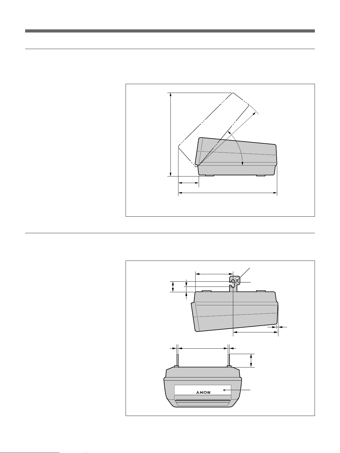
Necessary Dimensions for Ceiling Installation
Raise the brackets at the bottom.
/2)
1
63.5 (2
3 (1/8)
/2)
1
37.6 (1
251 (10)
362 (14 3/8)
Bracket
Hole used for installation
on the ceiling
320 (12 5/8)
3 (1/8)
/4)
3
93.5 (5
You may reattach the
nameplate upside down.
11 (7/16)
Unit: mm (inches)
Installation 5
Page 6
Before Installing
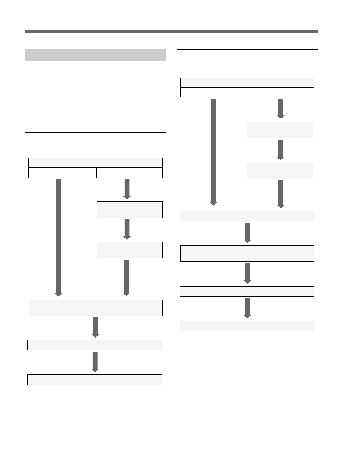
Installation Procedures
This projector is adjusted at the factory for projection
on a 100-inch front projection type screen when the
projector is installed on the floor/desk. If you install
the projector under other conditions, modifications of
some parts in the projector are required. Therefore,
installation procedures vary depending on the screen
size, installation method and type of screen.
Floor Installation Using Front Projection
Flat Screen
Select the screen size.
70-149 inches 150-250 inches
Change the CRT spacers.
(Page 19)
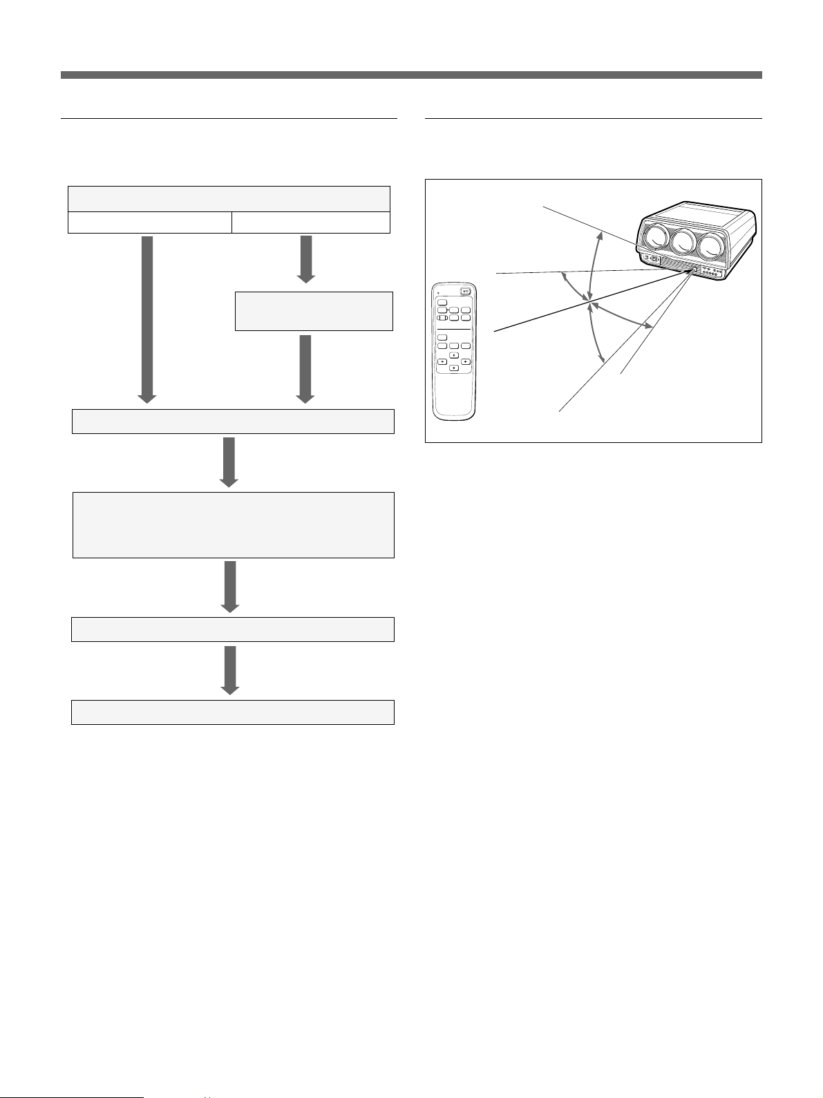
Ceiling Installation Using Front Projection
Flat Screen
Select the screen size.
70-149 inches 150-250 inches
Change the CRT spacers.
(Page 19)
Adjust the lens spacers.
(Page 23)
Change the polarity. (Page 24)
Adjust the lens spacers.
(Page 23)
Install the screen and the projector in accordance with the
standard measurements. (Page 8)
Adjust the lens focus. (Page 26)
Adjust the registration. (Page 27)
Install the screen and the projector in accordance with the
standard measurements. (Page 9)
Adjust the lens focus. (Page 26)
Adjust the registration. (Page 27)
6 Installation
Page 7
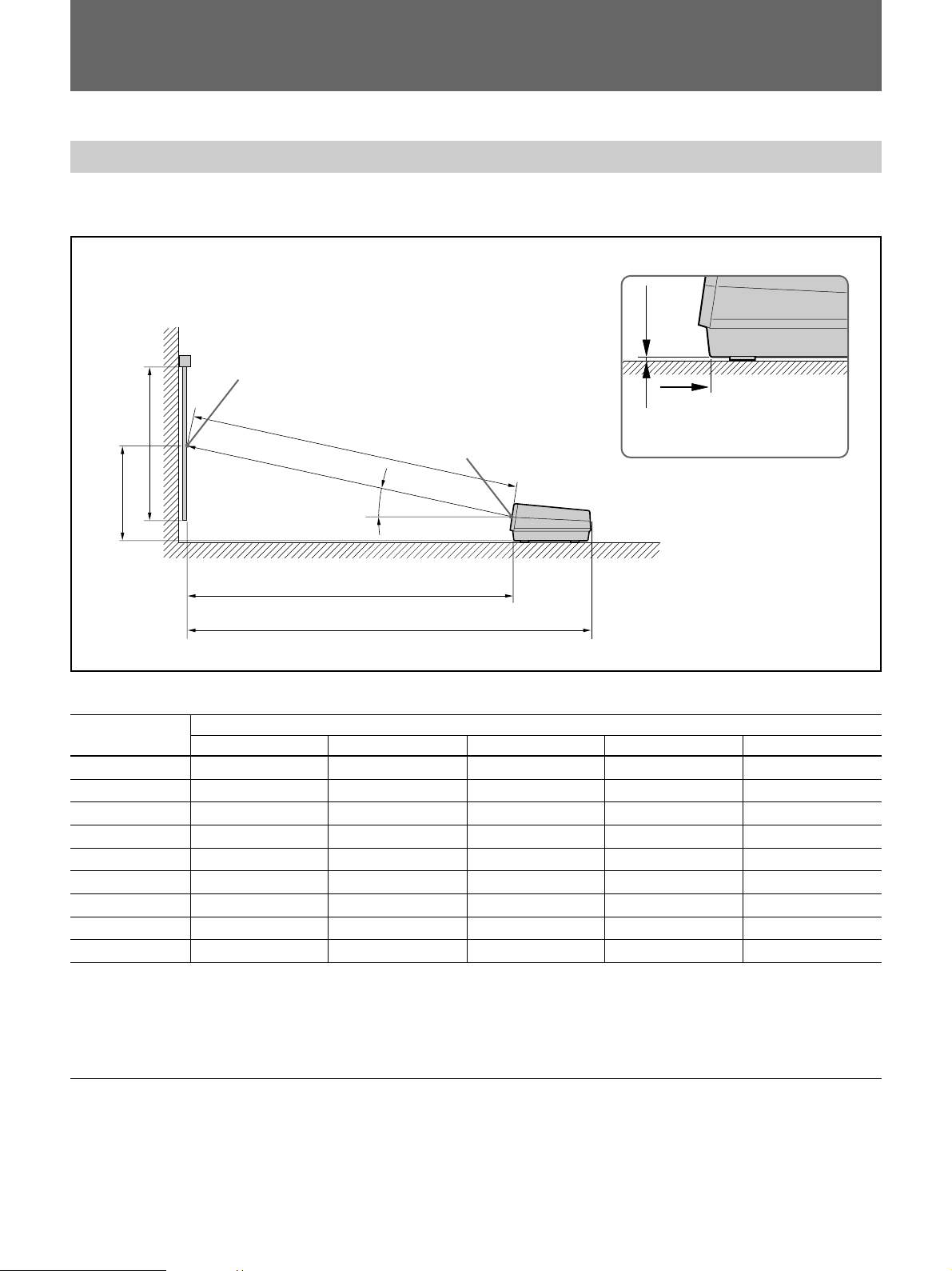
Floor or Ceiling Installation Using Rear
Projection Flat Screen
Determine the angle of optical axis.
12° 0° or 2°
Operable range of the Remote
Commander
30°
Change the CRT spacers.
(Page 19)
Change the polarity. (Page 24)
Install the screen and the projector in accordance with the
standard measurements.
• Floor installation (pages 11, 13)
• Ceiling installation (pages 12, 14)
Adjust the lens focus. (Page 26)
MUTING
PIC
VIDEO
RESET
TEST
R CENT B CENT
INPUT SELECT
S VIDEO INPUT A
M SEL
30°
ASPECT
PAGE
30°
30°
Approx. 7 m (23 feet) (max.)
Adjust the registration. (Page 27)
Installation 7
Page 8
Installation Diagrams
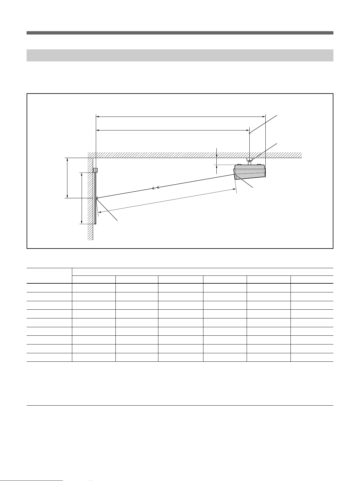
Installation Diagrams
Floor Installation Using Front Projection Flat Screen
Be sure that the projector is parallel to the floor.
B
Wall
Center of the screen
A
C
B
D
Screen size Length: mm (inches)
(inches) A B C D E
70 1,067 (42 1 / 8) 674 (26 5 / 8) 2,406 (94 3 / 4) 2,363 (93 1 / 8) 2,934 (115 5 / 8)
72 1,097 (43 1 / 4) 685 (27) 2,480 (97 3 / 4) 2,441 (96 1 / 8) 3,012 (118 5 / 8)
80* 1,219 (48) 740 (29 1 / 4) 2,734 (107 3 / 4) 2,681 (105 5 / 8) 3,252 (128 1 / 8)
100* 1,524 (60 1/ 8) 873 (34 3 / 8) 3,368 (132 5 / 8) 3,301 (130) 3,872 (152 1 / 2)
120** 1,829 (72 1 / 8) 1,006 (39 5 / 8) 4,004 (157
150 2,286 (90 1 / 8) 1,214 (47 7 / 8) 4,961 (195 3 / 8) 4,857 (191 1 / 4) 5,428 (213 3 / 4)
180 2,743 (108 1 / 8) 1,414 (55 3 / 4) 5,918 (231 1 / 8) 5,793 (228 1 / 8) 6,364 (250 5/ 8)
200 3,048 (120 1 / 16) 1,544 (60 7 / 8) 6,555 (258 1 / 8) 6,417 (252 3 / 4) 6,988 (275 1 / 4)
250 3,810 (150 1 / 8) 1,884 (74 1 / 4) 8,142 (320 5 / 8) 7,967 (313 3 / 4) 8,538 (336 1 / 4)
Center of the green lens
12°
E
Floor
11
/ 16) 3,923 (154 1 / 2) 4,494 (177)
16 mm
D
“B” and “D” correspond to
those in the illustration below.
Tolerance in length:±1%
*Sony screen VPS-80FH
**Sony screen VPH-100FH
***Sony screen VPS-120FH
Necessary modifications of parts(only for use of the 150- to 250-inch screens)
• CRT spacer change (page 19)
• Lens spacer adjustment (Page 23)
8 Installation
Page 9
Ceiling Installation Using Front Projection Flat Screen
Be sure that the projector is parallel to the ceiling. Use the Sony PSS-722
projector suspension support.
E
D
Ceiling
B
Center of the green lens
C
A
Center of the screen
Screen size Length: mm (inches)
(inches) A B C D E F
70 1,067 (42 1 / 8) 813 (32 1 / 8) 2,406 (94 3 / 4) 2,614 (103) 2,934 (115 5 / 8) 139 (5 1 / 2)
72 1,097 (43 1 / 4) 824 (32 1 / 2) 2,480 (97 3 / 4) 2,692 (106) 3,012 (118 5 / 8) 139 (5 1 / 2)
80* 1,219 (48) 879 (34 5 / 8) 2,734 (107 3 / 4) 2,932 (114 3 / 4) 3,252 (128 1 / 8) 139 (5 1 / 2)
100* 1,524 (60 1/ 8) 1,012 (39 7 / 8) 3,368 (132 5 / 8) 3,552 (139 7 / 8) 3,872 (152 1 / 2) 139 (5 1 / 2)
120** 1,829 (72 1 / 8) 1,145 (45 1 / 8) 4,004 (157
150 2,286 (90 1 / 8) 1,350 (53 1 / 4) 4,961 (195 3 / 8) 5,108 (201 1 / 8) 5,428 (213 3 / 4) 136 (5 3 / 8)
180 2,743 (108 1 / 8) 1,550 (61 1 / 8) 5,918 (231 1 / 8) 6,044 (238) 6,364 (250 5/ 8) 136 (5 3 / 8)
200 3,048 (120 1 / 16) 1,680 (66 1 / 4) 6,555 (258 1 / 8) 6,668 (262 5/ 8) 6,988 (275 1 / 4) 136 (5 3 / 8)
250 3,810 (150 1 / 8) 2,020 (79 9 / 16) 8,142 (320 5 / 8) 8,218 (323 5 / 8) 8,538 (336 1 / 4) 136 (5 3 / 8)
11
/ 16) 4,174 (164 3 / 8) 4,494 (177) 139 (5 1 / 2)
Rotation axis of the
PSS-722
PSS-722
Tolerance in length:±1%
Necessary modification of parts
*Sony screen VPS-80FH
**Sony screen VPS-100FH
***Sony screen VPS-120FH
• CRT spacer change (only for use of 150- to 250-inch screens) (page 19)
• Lens spacer adjustment (only for use of 150- to 250-inch screens) (page
23)
• Horizontal and vertical deflection changes (page 24)
Installation 9
Page 10

Installation Diagrams
When the Screen Size is Not Described in the Diagrams
When using the front projection flat screen for floor and ceiling
installations, use the following graph to decide the distance between the
screen and the projector (L).
L m L inches
8
300
7
250
6
5
4
3
Viewable area of the screen
200
150
100
72 100 150 200 250
234567
50 100 150 200
factory-preset
2345
Screen
A inches
A m
B inches
B m
10 Installation
A
B
3
/4B
L
Center of the green lens
Page 11

Floor Installation Using Rear Projection Flat Screen
When the angle of optical axis is 12°
C
B
“B” and “C” correspond to those in
the illustration below.
E
D
C
a
B
Floor
Wall
Center of the screen
A
a (angle of optical axis) =12°
Tolerance in length:±1%
Screen size Length: mm (inches)
(inches) A B C D E
70* 1,067 (42 1 / 8) 690 (27 1 / 4) 2,363 (93 1 / 8) 2,406 (94 3 / 4) 2,934 (115 5 / 8)
100 1,524 (60 1/ 8) 889 (35) 3,301 (130) 3,368 (132 5 / 8) 3,872 (152 1 / 2)
*Sony screen VPS-702R
Necessary modifications of parts
• Horizontal deflection change (page 24)
Installation 11
Page 12

Installation Diagrams
Ceiling Installation Using Rear Projection Flat Screen
When the angle of optical axis is 12°
E
C
PSS-722
Rotation axis of the PSS-722
Ceiling
a
B
Center of the screen
D
A
Wall
a (angle of optical axis)=12°
Tolerance in length:±1%
Screen size Length: mm (inches)
(inches) A B C D E
70* 1,067 (42 1 / 8) 674 (26 5 / 8) 2,614 (103) 2,406 (94 3 / 4) 2,934 (115 5 / 8)
100 1,524 (60 1/ 8) 873 (34 3 / 8) 3,552 (139 7 / 8) 3,368 (132 5 / 8) 3,872 (152 1 / 2)
*Sony screen VPS-702R
Necessary modifications of parts
• Vertical deflection change (page 24)
12 Installation
Page 13

Level Projection, Floor Installation
When the angle of optical axis is 0° or 2°
B
“B” and “D” correspond to those in
the illustration below.
b
Floor
D
C
B
a
D
E
Wall
Center of the screen
A
a (angle of optical axis)=0° or 2°
Tolerance in length:±1%
Screen size Length: mm (inches) Angle (°)
(inches) A B C D E a b
70*
100
1,067 (42 1 / 8) 165 (6 1 / 2) 2,397 (93 3 / 4) 2,439 (103) 2,982 (116 3 / 4)0 12
1,067 (42 1 / 8) 676 (26 5 / 8) 2,450 (95 3 / 4) 2,433 (95 7 / 8) 2,982 (116 3 / 4)2 10
1,524 (60 1/ 8) 167 (6 5/ 8) 3,368 (132 5 / 8) 3,402 (134) 3,954 (155 3 / 4)0 12
1,524 (60 1/ 8) 715 (28 1 / 4) 3,441 (135 1 / 2) 3,402 (134) 3,951 (155 5 / 8)2 10
*Sony screen VPS-702R
Necessary modifications of parts
• CRT spacer change (page 20)
• Horizontal deflection change (page 24)
Installation 13
Page 14

Installation Diagrams
Level Projection, Ceiling Installation
When the angle of optical axis is 0° or 2°
B
F
E
C
b
B
a
D
Wall
C
Center of the screen
“B” and “C” correspond to those in
the illustration below.
A
Center of the screen
a(angle of optical axis)=0° or 2°
Tolerance in length:±1%
Screen size Length: mm (inches) Angle (°)
(inches) A B C D E F a b
70*
100
1,067 (42 1 / 8) 165 (6 1 / 2) 2,397 (93 3 / 4) 2,439 (103) 2,698 (106 1 / 4) 2,982 (116 3 / 4)012
1,067 (42 1 / 8) 676 (26 5 / 8) 2,450 (94 3 / 4) 2,433 (95 7 / 8) 2,691 (106) 2,982 (116 3 / 4)210
1,524 (60 1/ 8) 167 (6 5/ 8) 3,368 (132 5 / 8) 3,402 (134) 3,669 (144 1 / 2) 3,954 (155 3 / 4)012
1,524 (60 1/ 8) 715 (28 1 / 4) 3,441 (135 1 / 2) 3,402 (134) 3,661 (144 1 / 4) 3,951 (155 5 / 8)210
*Sony screen VPS-702R
Necessary modifications of parts
• CRT spacer change (page 20)
• Vertical deflection change (page 24)
14 Installation
Page 15

Modifications of Parts
When modifying certain parts in the projector, such as changing polarity,
open the top panel, remove the cabinet, or detaching the lens block.
Opening the Top Panel
Use a medium size Philips head screwdriver.
1 Open the control panel cover and remove the two screws.
Panel cover
2 Pull the top panel slightly toward you and remove it.
Installation 15
Page 16

Modifications of parts
Removing the Cabinet
1 Open the control panel cover and remove the three screws on the
control panel.
2 Slide the nameplate upward and pull it toward you to remove.
3 Remove the two connectors from the control panel and remove the
control panel.
16 Installation
Page 17

4 Remove the three screws.
5 Raise the cabinet and slide it away from you to remove.
To reinstall the cabinet
Caution
Make sure that the cables inside the projector are not caught when
replacing the cabinet or the control panel.
1 Replace the cabinet.
2 Tighten the three screws on the nameplate attachment portion.
3 Connect the two connectors to the control panel, then replace the control
panel.
4 Insert the nameplate.
5 Tighten the three screws on the control panel.
Installation 17
Page 18

Modifications of parts
Detaching the Lens Block
1 Remove the cabinet.
2 Remove the 4 screws from the sides and the 4 screws from the lens
base of the projector.
3 Pull the lens block out toward you.
18 Installation
Page 19

Changing the CRT Spacer
To change the CRT spacers for 150- to 250- inch projection
Use an 8 mm nutdriver.
1 Remove the cabinet. (See “Removing the cabinet”.)
2 Detach the lens block. (See “Detaching the lens block”.)
3 Loosen the four nuts and remove the two spacers from the top and the
bottom of each CRT.
G spacer Spacer for 100" projection
G BR
4 Insert the supplied spacers for 200" front projection, 0.2 mm spacers
t and G spacers as follows:
Red and blue CRTs: A spacer for 200" and a 0.2 mm spacer t for the
top, a spacer for 200" for the bottom
Insert the spacer for 200” front projection with the thinner end toward the
center CRT.
Green CRT: The G spacer removed in step 3 and a 0.2 mm spacer t for
the top, the G spacer removed in step 3 for the bottom
Installation 19
Page 20

Modifications of parts
Spacer for 200" front projection
G spacer
R G B
(supplied)
0.2 mm spacer t
(supplied)
5 Tighten the four nuts of each CRT securely for accurate lens angles.
6 Reinstall the lens block, the cabinet and the top panel.
To change the CRT spacers for rear projection
Use an 8 mm nutdriver.
1 Remove the cabinet. (See “Removing the cabinet”.)
2 Detach the lens block. (See “Detaching the lens block.”)
3 Loosen the four nuts and remove two spacers from the top and the
bottom of each CRT.
G spacer Spacer for 100" projection
R G B
20 Installation
Page 21

4 Insert the supplied 0.8 mm spacers s for 100" rear projection, 0.2 mm
spacers t, the spacers for 100" projection and G spacers as follows:
When the angle of optical axis is 0°
Blue and red CRTs: A 0.8 mm spacer s and the spacer for 100"
removed in step 3 for the top, the spacer for 100" removed in step 3 for the
bottom
Green CRT: A 0.8 mm spacer s and the G spacer removed in step 3 for
the top, the G spacer for the bottom
0.8 mm spacer s for 100"
rear projection (supplied)
R G B
G spacer
Spacer for 100" projection*
* Spacers removed in step 3
Installation 21
Page 22

Modifications of parts
When the angle of optical axis is 2°
Red and blue CRTs: A 0.8 mm spacer s, a 0.2 mm spacer t and the
spacer for 100" removed in step 3 for the top, the spacer for 100" removed
in step 3 for the bottom
Green CRT: A 0.8 mm spacer s, 0.2 mm spacer t and the G spacer
removed in step 3 for the top, the G spacer removed in step 3 for the
bottom
0.8 mm space s for 100"
rear projection (supplied)
0.2 mm spacer t
R G B
G spacer*
Space for 100" projection*
*Spacers removed in step 3
5 Tighten the four nuts of each CRT securely for accurate lens angles.
22 Installation
6 Reinstall the lens block, the cabinet and the top panel.
Page 23

Adjusting the Lens Spacer for 150- to 250-inch Projection
1 Remove the cabinet.
2 Detach the lens block.
3 Detach the red and blue lenses from the lens base.
Remove the four nuts of each lens to detach.
4 Adjust the positions of the lens spaces.
For 100" projection
Guide mark
For 200" projection
Guide mark
100
100
Guide mark
Turn the ring so that the figure 200 is
aligned with the guide mark.
Align and
insert.
200
200
Guide mark
Installation 23
Page 24

Modifications of parts
Changing the Polarity
The projector is preset at the factory for use in front projection when
installed on the floor/desk. When the projector is installed on the ceiling or
used in rear projection, change the polarity. Horizontal and/or vertical
deflections should be changed depending on the type of installation.
Front projection, ceiling: Horizontal and vertical
Rear projection, floor/desk: Horizontal
Rear projection, ceiling: Vertical
To change
horizontal deflection
1
White lead
E-1
E-2
E-3
To change
vertical deflection
1
CN414
CN415
CN416
CN417
CN418
CN419
22
E board D board
S1
S2
HDC H1
Preparation
• Turn off the power.
• Open the top panel. (See page 15).
Changing the horizontal deflection
1 Reverse the polarity of connectors E-1, E-2 and E-
3 on the E board.
2 Set the S1 and S2 switches on the D board to the
control panel side position.
24 Installation
Changing the vertical deflection
1 Move the connectors on the D board from the
receptacles CN414, CN416 and CN418 to
receptacles CN415, CN417 and CN419,
respectively.
2 Set the S3, S4 and S5 switches on the D board to
the control panel side position.
Note
Make sure to insert the connectors firmly.
S3
S4
VDC V1
S5
V2
Page 25

Lens Focus Adjustment
The lens focus is adjusted at the factory for a 100” flat screen. For other
types of screens, you should adjust the lens focus.
5-2
MAIN
Blue Green Red
POWER n ON
Preparation
POWER n ON
1 2
TEST
5-1
For:
blue lens
green lens
red lens
B RAS G RAS R RAS
ON
OFF
OFF
BAR
HATCH
OFF
ON
OFF
BAR
OFF
OFF
ON
1 Install the projector in the correct location.
2 Open the top panel. (See page 15.)
3 Connect the supplied power cord (mains lead) to the AC IN socket and
to an AC outlet.
4 Press down the MAIN POWER switch. Press the POWER button on
the control panel, if necessary.
Adjustment 25
Page 26

Lens Focus Adjustment
Adjusting the Lens Focus
1 Press the TEST button on the control panel.
2 Set the BAR switch to HATCH.
A cross hatch pattern is displayed.
3 Check that the cross hatch pattern is displayed inside the screen. If not,
adjust the location of the projector.
4 Check that a white marker is displayed at the upper right as illustrated
below.
If not, correct the polarity. (See page 24.)
White marker
5 Adjust the lens focus.
1 Set the B RAG, G RAS and R RAS switches as illustrated above.
2 Adjust the focus of blue, green and red lenses as follows:
VPH-V20M/V20U
2 Loosen the screw, slide it to
adjust the focus on the
corners, then tighten it.
1 Loosen the screw, slide it to
adjust the focus on the
center, then tighten it.
VPH-V22M
2 Loosen the screw, slide the
three ribs to adjust the focus
Rib
on the corners, then tighten
the screw.
1 Loosen the screw, slide it to
adjust the focus on the
center, then tighten it.
26 Adjustment
Page 27

Registration Adjustment
Use a small screwdriver to adjust the controls through the holes.
MAIN POWER n O ON
B b v V
B CENT
R CENT
TEST
BAR n HATCH
Controls for registration adjustment
POWER n ON
Screen size
72”
(70”-85”)
100”
(85”-125”)
150”
(125”-175”)
200”
(175”-250”)
To adjust:
Red registration
Blue registration
MODEL
SELECT
B RAS G RAS R RAS
OFF
ON
100
100
200
200
SIZE
SELECT
ON
ON
150/72
NORMAL
150/72
NORMAL
ON
OFF
CENT SIZE LIN SKEW BOW
GV
MAIN-V-SIZE
MAIN-H-SIZE
GH
RV
RH
BV
BH
The circled numbers correspond to the step numbers (circled numbers) in the adjustment procedure on the next page.
MAIN-V-LIN
MAIN-V-BOW
MAIN-V-PIN
MAIN-H-PIN
TILT-1 TILT-2 TILT-3 TILT-4
MAIN-H-KEYS
These controls are used for the
reference green registration
adjustment. If necessary,
consult qualified Sony
personnel.
Adjustment 27
Page 28

Registration Adjustment
Preparations
1 Press the TEST button on the control panel to display the cross hair
2 Set the G RAS switch to ON and the B RAS and R RAS switches to
3 Check the location of the projector, polarity and lens focus.
4 Set the MODEL SELECT and SIZE SELECT switches to appropriate
Adjusting the Red Registration
Vertical registration adjustment
pattern.
OFF.
A green cross hatch pattern is displayed.
positions according to the screen size.
1 Set the B RAS switch to OFF and the G RAS and R RAS switches to
ON.
Green and red hatch patterns are displayed.
2 Press the R CENT button on the control panel and set the H and V
adjustment levels to “00” with the arrow buttons.
3 Adjust the RV CENT control so that the red and green horizontal lines
converge in the center of the screen.
4 Adjust the RV SIZE control (and the RV LIN control, if necessary) so
that the red and green horizontal lines converge at the upper and lower
sides of the screen.
Observe the horizontal lines in this part.
(If necessary, repeat steps 3 and 4.)
5 Adjust the RV SKEW and RV BOW controls if the red and green
horizontal lines do not converge in the middle of the screen.
6 Adjust the RV TILT-1 through TILT-4 controls so that the red and
green horizontal lines converge on the corners of the screen.
28 Adjustment
Page 29

Horizontal registration adjustment
7 Adjust the RH CENT control so that the red and green vertical lines
8 Adjust the RH SIZE control (and the RH LIN control, if necessary) so
(If necessary, repeat steps 7 and 8.)
9 Adjust the RH SKEW and RH BOW controls so that the red and green
!º Adjust the RH TILT-1 through TILT-4 controls so that the red and
Adjusting Blue Registration
converge in the center of the screen.
that the red and green vertical lines converge at the right and left sides
of the screen.
Observe the vertical lines in this part.
vertical lines converge in the middle of the screen.
green vertical lines converge on the corners of the screen.
Proceed to the following blue registration adjustment in the same manner
as with red registration adjustment. Set the R RAS switch to OFF and the
B RAS and G RAS switches to ON.
Vertical registration adjustment
!¡ Press the B CENT button on the control panel and set the H and V
adjustment levels to “00” with the arrow buttons.
!™ Adjust the BV CENT control to adjust the center of the screen.
!£ Adjust the BV SIZE control, and the BV LIN control if necessary, to
adjust the upper and lower sides of the screen.
!¢ Adjust the BV SKEW and BV BOW controls to adjust the middle of
the screen, if necessary.
!∞ Adjust the BV TILT-1 through TILT-4 controls to adjust jthe corners.
Horizontal registration adjustment
!§ Adjust the BH CENT control to adjust the center of the screen.
!¶ Adjust the BH SIZE control, and the BH LIN control if necessary, to
adjust the right and left sides of the screen.
!• Adjust the BH SKEW and BH BOW controls to adjust jthe middle of
the screen.
!ª Adjust the BH TILT-1 through TILT-4 controls to adjust the corners.
When the Registration Adjustment is Complete
1 Set the R RAS, G RAS and B RAS switches to ON, and the BAR
switch to BAR.
2 Press the TEST button on the control panel to return to the normal
display.
3 Reinstall the top panel. (See page 17.)
Adjustment 29
Page 30

Sony Corporation Printed in Japan
 Loading...