

Page 1

INTERFACE UNIT
PFV-L10
電気製品は、安全のための注意事項を守らないと、火災
や人身事故になることがあります。
このオペレーションマニュアルには、事故を防ぐための重要な注意事項と製
品の取り扱いかたを示してあります。このオペレーションマニュアルをよく
お読みのうえ、製品を安全にお使いください。お読みになったあとは、いつ
でも見られるところに必ず保管してください。
OPERATION MANUAL
[Japanese/English]
1st Edition (Revised 1)
Page 2
安全のために
ソニー製品は安全に十分に配慮して設計されています。しかし電気製品は、
安全のための注意事項を守らないと、火災や感電などにより死亡や大けがな
ど人身事故につながることがあり、危険です。
事故を防ぐために次のことを必ずお守りください。
安全のための注意事項を守る
2(J)〜 3(J)ページの注意事項をよくお読みください。
オプションユニットの装着について
危険を避けるために、オプションユニットの装着はサービストレーニングを
受けた技術者、もしくはソニーのサービス担当者または営業担当者にご依頼
ください。
定期点検を実施する
長期間安全に使用していただくために、定期点検を実施することをおすすめ
します。点検の内容や費用については、ソニーのサービス担当者または営業
担当者にご相談ください。
警告表示の意味
このオペレーションマニュアル
および製品では、次のような表
示をしています。表示の内容を
よく理解してから本文をお読み
ください。
この表示の注意事項を守らない
と、火災や感電などにより死亡
や大けがなど人身事故につなが
ることがあります。
この表示の注意事項を守らない
と、感電やその他の事故により
けがをしたり周辺の物品に損害
を与えたりすることがあります。
故障したら使用を中止する
ソニーのサービス担当者、または営業担当者にご連絡ください。
万一、異常が起きたら
1 電源を切る。
異常な音、に
おい、煙が出
たら
炎が出たら
,
2 電源コードや接続コードを抜く。
3 ソニーのサービス担当者、または営業担当者に
修理を依頼する。
すぐに電源を切り、消火する。
,
注意を促す記号
行為を禁止する記号
行為を指示する記号
Page 3

目次
警告 ..............................................................................................................
注意 ..............................................................................................................
概要 ................................................................................................................
特長 ..................................................................................................................4(J)
別売り基板 ............................................................................................................4(J)
各部の名称と働き .............................................................................................
仕様 .................................................................................................................
2 (J)
3 (J)
4 (J)
6 (J)
8(J)
日
本
語
1 (J)
Page 4
下記の注意を守らないと、
火災や感電により死亡や大けがにつながることがあります。
外装を外さない、改造しない
外装を外したり、改造したりすると、感電の原因となります。
内部の調整や設定および点検を行う必要がある場合は、必ずサービストレー
ニングを受けた技術者にご依頼ください。
内部に水や異物を入れない
水や異物が入ると火災や感電の原因となります。
万一、水や異物が入ったときは、すぐに電源を切り、電源コードや接続コー
ドを抜いて、ソニーのサービス担当者または営業担当者にご相談ください。
指定の電源コードを使用する
指定以外の電源コードを使用すると、火災や感電の原因となります。
他の電源コードを使用する場合は、ソニーのサービス担当者または営業担当
者にご相談ください。
電源コードを傷つけない
電源コードを傷つけると、火災や感電の原因となります。
電源コードを加工したり、傷つけたりしない。
•
重いものをのせたり、引っ張ったりしない。
•
熱器具に近づけたり、加熱したりしない。
•
電源コードを抜くときは、必ずプラグを持って抜く。
•
ラックマウントするとき、レールにはさみ込まない。
•
万一、電源コードが傷んだら、ソニーのサービス担当者に交換をご依頼くだ
さい。
油煙、湯気、湿気、ほこりの多い場所では設置•使用しない
上記のような場所で設置・使用すると、火災や感電の原因となります。
表示された電源電圧で使用する
機器に表示されたものと異なる電源電圧で使用すると、火災や感電の原因と
なります。
2 (J)
Page 5
下記の注意を守らないと、
けがをしたり周辺の物品に損害を与えることがあります。
通風孔をふさがない
通風孔をふさぐと内部に熱がこもり、火災や故障の原因となることがありま
す。風通しをよくするために次の項目をお守りください。
壁から10cm 以上離して設置する。
•
密閉された狭い場所に押し込めない。
•
毛足の長い敷物(じゅうたん・布団など)の上に設置しない。
•
布などで包まない。
•
あお向けや横倒し、逆さまにしない。
•
安定した場所に設置する
ぐらついた台の上や傾いたところなどに設置すると、製品が落下してけがの
原因となることがあります。
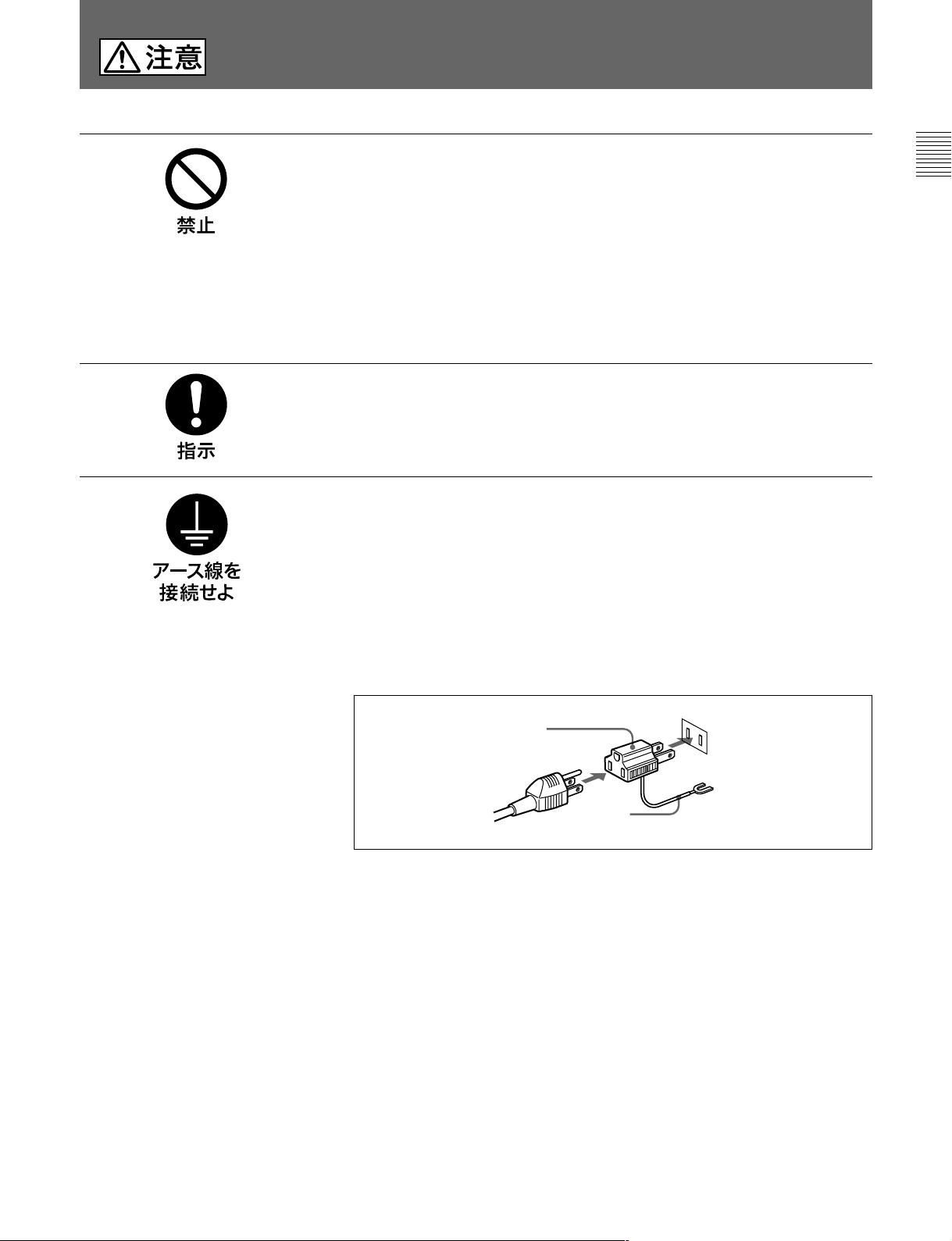
安全アースを接続する
安全アースを接続しないと、感電の原因となることがあります。次の方法で
アースを接続してください。
電源コンセントが3極の場合
•
指定の電源コードを使用することで安全アースが接続されます。
電源コンセントが2極の場合
•
指定の3 極→2 極変換プラグを使用し、変換プラグから出ている緑色の
アース線を建物に備えられているアース端子に接続してください。
変換プラグ
アース線
安全アースを取り付けることができない場合は、ソニーのサービス担当者ま
たは営業担当者にご相談ください。
3 (J)
Page 6

概要
イン ター フェ ースユニットPFV-L10は、アナログやデジタルの様々な
方式によるビデオ/オーディオ信号を扱う機器間のインターフェー
スをとるためのユニットです。
本体は、電源部、マザーボード、10個のオプション基板用スロットで
構成されています。
これらのスロ ットに オプ ション基板を装着する こ とで、本機から基板
に電源が供給され、基板の機能が動作します。別売りのオプショ
ン基 板群の中からシステ ムの目的に合わせ て基板 を選択 して本機
に装着することにより、1台のPFV-L10で各種の処理を行う柔軟性
に富んだシステム設計が可能となります。
特長
独立機能の基板による多様な処理への対応
別売りの基板により、様々なインターフェース機能を1台のPFV-L10
で構成することができます。最大10枚の基板を装着できます。
◆別売り基板については、「別売り基板」をご覧く ださい。
電源ブロックの使用による高信頼性
2
2系統の電源供給により、片方の電源が停止しても、もう一方から
の電源供給が行われる、信頼性の高い設計です。
別売り基板
次の基板の中から、使用の目的に合わせて必要な基板を選択し、
本機に装着します。
BKPF-L601C A/D
アナログコンポーネントビデオ信号(Y、R-Y、B-Y)またはRGB信号
を変換し 、4 系統の4:2:2コンポーネ ントシリアル デジタルビ デ オ
信号として出力します。525/625ラインは、入力信号より自動判別
します。
BKPF-L602C
4:2:2シリアルデジタルビデオ信号をD/A変換し、G/B/R/SYNC
またはY/B-Y/R-Y/SYNC信号として出力 し ます。
BKPF-L603 SDI
コ ンポジットまたはコンポーネン トのシ リアルデジ タルビデオ信号を
8分配します。
BKPF-L605
(コンポーネント
シリアルデジタルビデオ信号にAES/EBUフォーマットのデジタル
オーディ オ信号を多重 します。
コンバーター
ビデオ
ディストリビューター
オーディオ/ビデオマルチプレクサー
/NTSC
コンバーター
D/A
コンポジット)
ラックマウント
EIAの19インチラッ ク にマウントできるサイズになっています。
ラックマウント時には、 ラックマウントキッ トRMM-10を取り付ける構
造になっていま す。RMM-10を装着する場合は、ソニーのサービ
ス担当者にご依頼ください。
BKPF-L606
(コンポーネント
オーディオ信号が多重されたシリ アルデジタルビデオ信号から
AES/EBUフォーマットのデジ タルオーディオ信号 を分離し、分離し
たデジタルオーディオ信号と、入力したシリアルデジタル信号をそ
のま ま出力 します。
BKPF-L608C
4:2:2コンポーネント シリ アルデジ タルビデオ信号を、 アナログのリ
ファレンス信号に同期させる シン クロナイ ザ−機能を持っています。
BKPF-L611 3
3系統の入力信号をそれぞれ2分配して出力します。入力信号は、
540Mbps、360Mbps、270Mbps(4:2:2SDI)、177Mbps(4fscPAL
SDI)、143Mbps(4fscNTSCSDI)の5つのフォーマットに 対 応し て
います。
オーディオ/ビデオデマルチプレクサー
/NTSC
フレームシンクロナイザーボード
チャンネル
コンポジット)
ディストリビューションボード
SDI
4 (J)
Page 7

BKPF-L612 2
2系統の入力信号をそれぞれ4分配して出力します。入力信号は、
540Mbps、360Mbps、270Mbps(4:2:2SDI)、177Mbps(4fscPAL
SDI)、143Mbps(4fscNTSCSDI)の5つのフォーマットに 対 応し て
います。
BKPF-L613C
ビューター(コンポーネント)
コンポーネン トシリアルデジタル ビ デオ信号を4分配して出力すると
ともに、モニター用としてア ナログ信号に変換し て出力します。
BKPF-L632
4:2:2コンポーネントSDI信号を、NTSC/PALコンポジット アナログ
ビデオ信号に変換 します。2系統の入力信号をそれぞれ3分配して
出力します。
チャンネル
アナログモニター機能付き
モニタリングコンポジットエンコーダーボード
BKPF-L641 NTSC/PAL to 4:2:2
アナログNTSC/PALコンポジット信 号を、 525/625ライン4:2:2コン
ポーネントシリアルデジタルビデオ信号に変換します。
BKPF-L642 4:2:2 to NTSC/PAL
525/625ライン4:2:2コンポーネントシリアルデジタルビデオ信号を、
アナログNTSC/PALコンポジット信号に 変 換します。
BKPF-L703A
1系統のアナログビデオ信号を8系統に分配して出力します。
BKPF-L704
入力ビデオ信号に同期したブ ラックバースト信 号を生成して、出力
します。 出力数は6出力で、出力位相は−4H〜+4Hの範囲で連
続的に可変できます。約40IREまでセットアップを付加する機能も
備えています。
アナログビデオディストリビューター
ブラックバーストリジェネレーターボード
ディストリビューションボード
SDI
ディストリ
SDI
ボード
ボード
BKPF-L751
4チャ ン ネルのアナログオーディオ信号をA/D変換 し、2系統の
AES/EBU信号をとして出力します。サンプリ ング周波数は48kHz
で、分解能24ビットのΔΣ方式のA/D変換ICを使用しています。
入力チャンネル1/2と3/4の信号を、AES/EBU1、2 のどちら かか
ら出力することができます。基準信号は、525/625のビデオ信号、
HDの3値シンク、48kHzのワ−ドクロックが使用可能です。また、
ワ− ドクロックを基準信号として出力できます。
BKPF-L752
2系統のAES/EBU信号をD/A変換し、4チャンネルのアナログ
オー ディオ 信 号とし て 出 力します 。サンプリング周波数は48kHz
で、分解能24ビットのΔΣ方式のD/A変換ICを使用しています。
また、ディ エンファシスをON/OFFすることができます。
BKPF-L753A
1系統のアナログステレオオー デ ィオ信号を4系統に、また 1 系統
のアナログモノラルオーディオ信号を8 系統に分配して出力しま
す。基板上のスイッチの設定で、アナログオーディ オ信号の入出力
ゲインをミ8、ミ4、0、+4、+8dBから選択できます。また、 基板上のボ
リュー ムで、選択したゲインごとに±2dBの範囲でゲインを連続調
整する ことができます。
BKPF-L754
400Hz(または440Hz)および1kHzの発振器を内蔵し、2系統
の出力からそれぞれ異なる周波数の信号を供給することができま
す。 出力レベルは、0dBm、+4dBm、+8dBmから選択することも
できますし、ボリュームにより0〜10dBmの範囲で連続調整する
こ と もでき ます。
オーディオ
オーディオ
アナログオーディオディストリビューター
オーディオシグナルジェネレーターボード
コンバーターボード
A/D
コンバーターボード
D/A
BKPF-L723
入力ビデオ信号を最大約1.5µsec遅延して出力します。出力数は
最大6出力です。遅延量は、350nsec単位で3段階、75nsec単位
で5段階、15nsec単位で5段階の調整が可能で、さらに15nsecの
微調整ができます。また、300mまでのケーブル補償調整機能を
持っていま す。
ビデオディレイディストリビューションボード
5 (J)
Page 8

各部の名称と働き
1
インジケーター
2
POWER
3
前面
A
スイッチ
インジケーター
4
POWER
A
B
スイッチ
B
INTERFACE UNIT
PFV-L10
B
POWER
I
O
5
ブランクパネル
後面
1
インジケーター
A
POWER
I
O
A
電源ユニットA の電源が入る と緑色に点灯 します。
次のような場合、赤く点滅します。
•電源ユニット内の温度が規定以上に上昇した場合
•換気用ファンが停止した場合
•電源ユニットBのみが電源ONの場合、または電源ユニットA の
出力電圧に異常が生じた場合
•電源負荷が規定以上に大きい場合。
-AC IN
A
B
STATUS OUT
U
9
〜AC IN端子B
8
〜AC IN端子A
3
インジケーター
7
STATUS OUT
6 U
信号用アース)端子
(
B
端子
電源ユニットB の電源が入る と緑色に点灯 します。
次のような場合、赤く点滅します。
•電源ユニット内の温度が規定以上に上昇した場合
•換気用ファンが停止した場合
•電源ユニットAのみが電源ONの場合、または電源ユニットB の
出力電圧に異常が生じた場合
•電源負荷が規定以上に大きい場合。
2
POWER (電源)
スイッチ
A
電源ユニットAの電源をON/OFFします。
6 (J)
4
POWER (電源)
スイッチ
B
電源ユニットBの電源をON/OFFします。
Page 9

5
ブランクパネル
基板を取り付ける と きは外します。
6
U(信号用アース)端子
必要に応じて接地してください。
7
STATUS OUT (
ステータス出力) 端子
次の情報を外部機器に出力します。
•基板が正しく動作していない。
•内部の温度が規定以上に上昇している。
•電源ユニットの出力電圧に異常が生じた。
•電源がOFFになっている。
•換気用ファンが停止している。
•電源の負荷が規定以上に大きい。
(D-sub 15ピン)
8
〜AC IN(AC
電源入力)端子
A
電源ユニットAのAC電源入力端子です。
指定の電源コードを使ってAC電源を接続します。
9
〜AC IN(AC
電源入力)端子
B
電源ユニットBのAC電源入力端子です。
指定の電源コードを使ってAC電源を接続します。
Pin No
1スロット1に装着した基板のステータス出力
2スロット2に装着した基板のステータス出力
3スロット3に装着した基板のステータス出力
4スロット4に装着した基板のステータス出力
5スロット5に装着した基板のステータス出力
6スロット6に装着した基板のステータス出力
7スロット7に装着した基板のステータス出力
8スロット8に装着した基板のステータス出力
9スロット9に装着した基板のステータス出力
10 電源ユニットB の状態
11 電源ユニットA の状態
1 2 換 気 用ファンの 状 態
13 電源負荷状態
14 スロット10に装着した基板のステータス出力
15 GND
機能
正常時:ローレベル
正常時:ローレベル
正常時:ローレベル
正常時:ローレベル
正常時:ローレベル
正常時:ローレベル
正常時:ローレベル
正常時:ローレベル
正常時:ローレベル
正常時:ローレベル
正常時:ローレベル
正常時:ローレベル
正常時:ローレベル
正常時:ローレベル
7 (J)
Page 10

仕様
電源電圧 AC100〜120/220〜240V、50/60Hz
消費電流 100V:1.4A、240V:0.58A
供給可能電力 +5VDC最大13A
使用温度 +5℃〜40℃
保存温度 −20℃〜+60℃
湿度 30〜70%(25℃)
最大外形寸法 440×88×353mm(幅/高さ/奥行き)
重量 約7.0kg(別売り基板含まず)
ステータス出力 STATUSOUT:D-sub15ピン
付属品 オペレーションマニュアル(1)
インストレーシ ョンマニュ アル(1)
別売り品
AC電源コード(125V、10A、2.5m)
部品番号:1-776-997-11
ACプラグ変換アダプター(3ピン→ 2ピン)
部品番号:1-793-461-11
RMM-10ラックマウントキッ ト
仕様および外観は、改良のため予告なく変更することがあります
が、ご了承ください。
8 (J)
Page 11

WARNING
To prevent fire or shock hazard, do not expose the unit to
rain or moisture.
To avoid electrical shock, do not open the cabinet. Refer
servicing to qualified personnel only.
THIS APPARATUS MUST BE EARTHED.
AVERTISSEMENT
WARNING: THIS WARNING IS APPLICABLE FOR USA
ONLY.
If used in USA, use the UL LISTED power cord specified
below.
DO NOT USE ANY OTHER POWER CORD.
Plug Cap Parallel blade with ground pin
(NEMA 5-15P Configuration)
Cord Type SJT, three 16 or 18 AWG wires
Length Less than 2.5 m (8 ft. 3in.)
Rating Minimum 10 A, 125 V
English
English
Afin d’éviter tout risque d’incendie ou d’électrocution, ne pas
exposer cet appareil à la pluie ou à l’humidité.
Afin d’écarter tout risque d’électrocution, garder le coffret
fermé. Ne confier l’entretien de l’appareil qu’à un personnel
qualifié.
CET APPAREIL DOIT ÊTRE RELIÉ À LA TERRE.
VORSICHT
Um Feuergefahr und die Gefahr eines elektrischen Schlages
zu vermeiden, darf das Gerät weder Regen noch
Feuchtigkeit ausgesetzt werden.
Um einen elektrischen Schlag zu vermeiden, darf das
Gehäuse nicht geöffnet werden. Überlassen Sie
Wartungsarbeiten stets nur qualifiziertem Fachpersonal.
DIESES GERÄT MUSS GEERDET WERDEN.
For the customers in the USA
This equipment has been tested and found to comply with
the limits for a Class A digital device, pursuant to Part 15 of
the FCC Rules. These limits are designed to provide
reasonable protection against harmful interference when the
equipment is operated in a commercial environment. This
equipment generates, uses, and can radiate radio frequency
energy and, if not installed and used in accordance with the
instruction manual, may cause harmful interference to radio
communications. Operation of this equipment in a residential
area is likely to cause harmful interference in which case the
user will be required to correct the interference at his own
expense.
Using this unit at a voltage other than 120 V may require the
use of a different line cord or attachment plug, or both. To
reduce the risk of fire or electric shock, refer servicing to
qualified service personnel.
WARNING: THIS WARNING IS APPLICABLE FOR OTHER
COUNTRIES.
1. Use the approved Power Cord (3-core mains lead)/
Appliance Connector/Plug with earthing-contacts that
conforms to the safety regulations of each country if
applicable.
2. Use the Power Cord (3-core mains lead)/Appliance
Connector/Plug conforming to the proper ratings (voltage,
ampere).
If you have questions on the use of the above Power Cord/
Appliance Connector/Plug, please consult a qualified service
personnel.
You are cautioned that any changes or modifications not
expressly approved in this manual could void your authority
to operate this equipment.
The shielded interface cable recommended in this manual
must be used with this equipment in order to comply with the
limits for a digital device pursuant to Subpart B of Part 15 of
FCC Rules.
This symbol is intended to alert the user to the
presence of important operating and
maintenance (servicing) instructions in the
literature accompanying the appliance.
1 (E)
Page 12

Table of Contents
For the customers in Europe
This product with the CE marking complies with both the
EMC Directive (89/336/EEC) and the Low Voltage Directive
(73/23/EEC) issued by the Commission of the European
Community.
Compliance with these directives implies conformity to the
following European standards:
• EN60950: Product Safety
• EN55103-1: Electromagnetic Interference (Emission)
• EN55103-2: Electromagnetic Susceptibility (Immunity)
This product is intended for use in the following
Electromagnetic Environment(s):
E1 (residential), E2 (commercial and light industrial), E3
(urban outdoors) and E4 (controlled EMC environment, ex.
TV studio)
Pour les clients européens
Ce produit portant la marque CE est conforme à la fois à la
Directive sur la compatibilité électromagnétique (EMC) (89/
336/CEE) et à la Directive sur les basses tensions (73/23/
CEE) émises par la Commission de la Communauté
Européenne.
La conformité à ces directives implique la conformité aux
normes européennes suivantes:
• EN60950: Sécurité des produits
• EN55103-1: Interférences électromagnétiques (émission)
• EN55103-2: Sensibilité électromagétique (immunité)
Ce produit est prévu pour être utillisé dans les
environnements électromagnétiques suivants:
E1 (résidentiel), E2 (commercial et industrie légère), E3
(urbain extérieur) et E4 (environnement EMC contrôlé ex.
studio de télévision).
Overview.............................................................. 3 (E)
Features ........................................................... 3 (E)
Optional Boards............................................... 3 (E)
Locations and Functions of Parts...................... 5 (E)
Specifications....................................................... 7 (E)
Für Kunden in Europa
Dieses Produkt besitzt die CE-Kennzeichnung und erfüllt
sowohl die EMV-Direktive (89/336/EEC) als auch die
Direktive Niederspannung (73/23/EEC) der EG-Kommission.
Die Erfüllung dieser Direktiven bedeutet Konformität für die
folgenden Europäischen Normen:
• EN60950: Produktsicherheit
• EN55103-1: Elektromagnetische Interferenz (Emission)
• EN55103-2: Elektromagnetische Empfindlichkeit
(Immunität)
Dieses Produkt ist für den Einsatz unter folgenden
elektromagnetischen Bedingungen ausgelegt:
E1 (Wohnbereich), E2 (kommerzieller und in beschränktem
Maße industrieller Bereich), E3 (Stadtbereich im Freien) und
E4 (kontrollierter EMV-Bereich, z.B. Fernsehstudio).
2 (E)
Page 13

Overview
The PFV-L10 Interface Unit is an apparatus for
interfacing various kinds of equipment to process
analog and digital video and audio signals. The unit is
composed of a power block, a main board and then
slots to accommodate optional boards .
When an optional board is installed in one of the slots,
the power is supplied from the PFV-L10 to the board,
and the functions of the board are activated. Select the
appropriate optional boards and install them into the
PFV-L10, allowing the unit to execute various signalprocessing functions.
Features
Various kinds of signal processing with
optional boards
With the appropriate optional boards installed, various
functions regarding serial digital video signals can be
processed in a single PFV-L10 unit.
Up to then boards can be installed in combination in
the PFV-L10.
For the optional boards, see the next section.
Reliable operation assured by two AC lines
A pair of built-in power supply units enable the PFVL10 to be supplied with power from two separate lines.
If one of the power blocks stops supplying power, the
other block will supply full power. Thus, highly
reliable operation is maintained.
Rack mounting
The unit can be mounted in a standard 19-inch rack.
To mount the unit to the rack, the RMM-10 Rack
Mount Kit is necessary. For mounting the RMM-10,
consult your Sony service personnel.
Optional Boards
Select boards with the required functions, and install
them in slots of the PFV-L10.
BKPF-L601C A/D Converter
This board converts the analog component video
signals (Y, R-Y, B-Y) or the RGB signals to the digital
signals, and supplies them as four lines of the 4:2:2
component serial digital video signals.
BKPF-L602C Video D/A Converter
This board converts the 4:2:2 serial digital video signal
to analog signals, and supplies them as the G/B/R/
SYNC or Y/B-Y/R-Y/SYNC signals.
BKPF-L603 SDI Distributor
This board distributes a composite or component serial
digital video signal to eight outputs.
BKPF-L605 Audio/Video Multiplexer
(Component/NTSC Composite)
This board multiplexes AES/EBU-format digital audio
signals to a serial digital video signal.
BKPF-L606 Audio/Video Demultiplexer
(Component/NTSC Composite)
This board demultiplexes AES/EBU-format digital
audio signals from a serial digital signal, and outputs
the demultiplexed audio signal and the input serial
digital signal as is.
BKPF-L608C Frame Synchronizer Board
This board has a function to synchronize 4:2:2
component serial digital video signals with the
reference audio signal.
BKPF-L611 3-ch SDI Distribution Board
This board accepts three input signals, each of which is
divided into two and output. The unit conforms to five
signal formats: 540 Mbps, 360 Mbps, 270 Mbps (4:2:2
SDI), 177 Mbps (4fsc PAL SDI), and 143 Mbps (4fsc
NTSC SDI).
BKPF-L612 2-ch SDI Distribution Board
This board accepts two input signals, each of which is
divided into four and output. The unit conforms to
five signal formats: 540 Mbps, 360 Mbps, 270 Mbps
(4:2:2 SDI), 177 Mbps (4fsc PAL SDI), and 143 Mbps
(4fsc NTSC SDI).
3 (E)
Page 14

Overview
BKPF-L613C SDI Distributor with Analog
Monitor Out (Component)
This board distributes a component serial digital video
signals to four outputs, and converts it to an analog
signal for monitoring.
BKPF-L632 Monitoring Composite Encoder
Board
This board converts a 4:2:2 component SDI signal to
an NTSC or PAL composite analog video signal. The
unit accepts two channel signals, each of which is
divided into three and output.
BKPF-L641 NTSC/PAL to 4:2:2 Board
This board converts analog NTSC/PAL composite
video signals to 525/625-line 4:2:2 component serial
digital video signals.
BKPF-L642 4:2:2 to NTSC/PAL Board
This board converts 525/625-line 4:2:2 component
serial digital video signals to analog NTSC/PAL
composite video signals.
BKPF-L703A Analog Video Distributor
This board distributes a serial digital video signal to
eight outputs.
BKPF-L704 Black Burst Regenerator Board
This board generates a black burst signal which is
synchronized with an input signal. The board supplies
six output signals whose phase can be adjusted
between –4H and +4H continuously. Setup up to
about 40 IRE can be added.
BKPF-L723 Video Delay Distribution Board
The signal input to this board is delayed up to 1.5
µsec, and the delayed signal is supplied to up to six
output lines. The amount of delay can be adjusted in
three steps of 350 nsec, five steps of 75 nsec, or five
steps of 15 nsec, and also up to 15 nsec by fine
adjustment. Cable compensation up to 300 meters
long is also available.
BKPF-L751 Audio A/D Converter Board
This board converts the four-channel analog audio
signals to AES/EBU format digital audio signals,
which are supplied to two audio lines. The sampling
frequency is 48 kHz, and a ∆Σ-system A/D conversion
IC with 24-bit resolution is used. The signals input to
channels 1/2 and 3/4 can be supplied to either the
AES/EBU 1 or 2 output. As a reference signal, a 525/
625 video signal, an HD 3-value sync signal, or a 48
kHz word clock can be used, and the word clock signal
can be output as a reference signal.
BKPF-L752 Audio D/A Converter Board
This board converts the AES/EBU format digital audio
signals of two lines to analog audio signals, which are
output as the four-channel analog audio signals. The
sampling frequency is 48 kHz, and a ∆Σ-system D/A
conversion IC with 24-bit resolution is used. The deemphasis function is set to ON or OFF.
BKPF-L753A Analog Audio distributor
This board divides a pair of analog stereo audio
signals, and distributes them to four lines, or one
monaural audio signal to eight lines, and supplies the
divided signals. The gain of the input and output
signals can be selected with the switches on the board
among from –8, –4, 0, +4, and +8 dB, and it can also
be continuously adjusted with the control on the board
within the range of ±2 dB for each selected gain.
BKPF-L754 Audio Signal Generator Board
This board generates 400 Hz (or 440 Hz) and 1 kHz
signals, which are output from two output lines. The
output-signal frequency can be set for each line, and
the output signal level can be set to 0 dBm, +4 dBm, or
+8 dBm or can be controlled continuously with the
control knob.
4 (E)
Page 15

Locations and Functions of Parts
1 Indicator A
2 POWER A switch
3 Indicator B
4 POWER B switch
Front panel
INTERFACE UNIT
PFV-L10
B
POWER
I
O
Rear panel
A
POWER
I
O
1 Indicator A
Lights in green when power unit A is turned on.
Flashes in red in the following cases:
•The temperature inside power unit has risen to a
specified level.
•The ventilation fans have stopped rotating.
•Only power unit B is turned on, or trouble occurs
with the output voltage of power unit A.
•A voltage load exceeds the specified level.
Cover plates
5
-AC IN
A
B
STATUS OUT
U
9 ~AC IN B connector
8 ~AC IN A connector
7 STATUS OUT connector
6 U (signal ground) terminal
3 Indicator B
Lights in green when power unit B is turned on.
Flashes in red in the following cases:
•The temperature inside power unit has risen to a
specified level.
•The ventilation fans have stopped rotating.
•Only power unit A is turned on, or trouble occurs
with the output voltage of power unit B.
•A voltage load exceeds the specified level.
2 POWER A switch
Turns on and off power unit A.
4 POWER B switch
Turns on and off power unit B.
5 (E)
Page 16

Locations and Functions of Parts
5 Cover plates
Remove the corresponding plates to install the optional
boards.
6 U (signal ground) terminal
For signal ground. Connect to a ground wire as
required.
7 STATUS OUT connector (15-pin)
Outputs the following error statuses of the PFV-L10.
•The inserted optional board does not function
correctly.
•The temperature inside the unit has risen to a
specified level.
•Trouble occurs with the output voltage of power unit
A or B.
•The power is turned off.
•The ventilation fans have stopped rotating.
•A voltage overload has occurred.
Pin No. Functions
1 Status output of the board inserted in slot 1.
Normal: Low level
2 Status output of the board inserted in slot 2.
Normal: Low level
3 Status output of the board inserted in slot 3.
Normal: Low level
4 Status output of the board inserted in slot 4.
Normal: Low level
5 Status output of the board inserted in slot 5.
Normal: Low level
6 Status output of the board inserted in slot 6.
Normal: Low level
7 Status output of the board inserted in slot 7.
Normal: Low level
8 Status output of the board inserted in slot 8.
Normal: Low level
9 Status output of the board inserted in slot 9
Normal: Low level
10 Status output of the power unit B.
Normal: Low level
11 Status output of the power unit A.
Normal: Low level
12 Status output of the ventilation fans.
Normal: Low level
13 Status output of the voltage load.
Normal: Low level
14 Status output of board inserted in slot 10
Normal: Low level
15 GND
8 ~AC IN A connector
To supply power to power unit A, connect to an AC
power supply using an appropriate AC power cord.
9 ~AC IN B connector
To supply power to power unit B, connect to an AC
power supply using an appropriate AC power cord.
6 (E)
Page 17

Specifications
Power requirements 100 to 120/220 to 240 V AC,
50/60 Hz
Current drain 100 V: 1.4 A, 240 V: 0.58 A
Peak inrush current
(1) Power ON, current probe method: 20 A (100 V),
25 A (240 V)
(2) Hot switching inrush current, measured in
accordance with European
standard EN55103-1: 18 A
(230 V)
Power supply capacity +5 V DC: max. 13 A
Operating temperature 5°C to 40°C (41°F to 104°F)
Storage temperature –20°C to +60°C
(–4°F to +140°F)
Operating humidity 30% to 70% (at 25°C/77°F)
Dimensions 440 × 88 × 353 mm (w/h/d)
Mass Approx. 7.0 kg (15 lb 43 oz)
Status output STATUS OUT: D-sub 15-pin
Supplied accessories Operation Manual (1)
7
/8 × 3 1/2 × 14 inches)
(16
(not including the optional
boards)
Installation Manual (1)
Optional accessories
AC power cord (for USA and Canada only)
125 V, 10 A, 2.4 m (8 ft.)
Part No.: 1-557-377-11
AC power cord (for Europe only)
250 V, 10 A, 2.4 m (8 ft.)
Part No.: 1-782-929-21
RMM-10 Rack Mount Kit
Design and specifications are subject to change
without notice.
7 (E)
Page 18

Page 19

The material contained in this manual consists of
information that is the property of Sony Corporation and is
intended solely for use by the purchasers of the equipment
described in this manual.
Sony Corporation expressly prohibits the duplication of any
portion of this manual or the use thereof for any purpose
other than the operation or maintenance of the equipment
described in this manual without the express written
permission of Sony Corporation.
Le matériel contenu dans ce manuel consiste en
informations qui sont la propriété de Sony Corporation et
sont destinées exclusivement à l’usage des acquéreurs de
l’équipement décrit dans ce manuel.
Sony Corporation interdit formellement la copie de quelque
partie que ce soit de ce manuel ou son emploi pour tout
autre but que des opérations ou entretiens de l’équipement
à moins d’une permission écrite de Sony Corporation.
Das in dieser Anleitung enthaltene Material besteht aus
Informationen, die Eigentum der Sony Corporation sind,
und ausschließlich zum Gebrauch durch den Käufer der in
dieser Anleitung beschriebenen Ausrüstung bestimmt sind.
Die Sony Corporation untersagt ausdrücklich die
Vervielfältigung jeglicher Teile dieser Anleitung oder den
Gebrauch derselben für irgendeinen anderen Zweck als die
Bedienung oder Wartung der in dieser Anleitung
beschriebenen Ausrüstung ohne ausdrückliche schriftliche
Erlaubnis der Sony Corporation.
Page 20

PFV-L10 (SY, 和, 英)
3-866-912-02(1)
Sony Corporation
B & P Company
Printed in Japan
2002.11.13
1999
 Loading...