

Page 1

™
VAIO Slimtop
LCD
Computer User Guide
PCV-L620
®
i
Page 2

© 1999 Sony Electronics Inc. Reproduction
in whole or in part without written
permission is prohibited. All rights
reserved. This manual and the soft ware
described herein, in whole or in part, may
not be reproduced, translated, or reduced
to any machine-readable form without
prior written approval.
Sony, VAIO, the VAIO lo go, VAIO Slimtop,
Ergo-Angle, AutoAlert, VAIO Smart,
Handycam, VAIO Digital Studio, Memory
Stick, i.LINK, Media Bar, Mavica, and
PictureGear are trademarks of Sony.
Windows and the Windows logo are
registered trademarks of Microsoft
Corporation. K56flex is a trademark of
Lucent Technologies Inc. and Rockwell
International. All other trademarks are
trademarks of their respective owners.
Declaration of Conformity
Trade Name: SONY
Model No.: PCV-L620
Responsible Party:
Address:
Telephone No: 201-930-6970
This device complies with Part 15 of FCC Rules.
Operation is subject to the two following
conditions: (1) This device may not cause harmful
interference, and (2) this device must accept any
interference received, including interference that
may cause undesired operation.
Sony Electronics Inc.
1 Sony Drive
Park Ridge, NJ 07656
Owner’s Record
The model number and serial
number are located on the back of
your Sony computer. Record the
model and serial numbers in the
space provided here. Refer to the
model and serial numbers when
you call your Sony Service Center.
Model Number:_____________
Serial Number:______________
Page 3

Contents
Features .............................................................................................1
Unpacking Your Computer............................................................ 3
Locating Controls and Connectors................................................ 5
Attaching the Stand to the System Unit .....................................12
Configuring Microsoft
Registering Your Computer......................................................... 14
Using the Programmable Power Keys (PPK) ............................15
Using Memory Stick™ Media......................................................22
Using PC Cards..............................................................................25
Using the Standby Function.........................................................27
Shutting Down Your Computer.................................................. 28
Using the System Recovery CD(s)............................................... 30
Using the Application Recovery CD(s) ...................................... 32
About the Software on Your Computer .....................................33
For Answers to Your Software Questions.................................. 38
Troubleshooting.............................................................................40
Specifications..................................................................................44
Index................................................................................................ 47
®
Windows® 98 Second Edition...........13
Page 4

Page 5

Features
For a complete description of the specifications of your Sony computer, see “Specifications”
✍
on page 44.
❑
i.LINK® (IEEE-1394): Two built-in i.LINK ports provide you with
front and rear digital connection capability. The i.LINK name and
logo identify a digital interface (IEEE-1394) for high speed
communication.
❑
Exceptional performance: Your computer includes a fast Intel®
processor and a V.90 compatible data/fax modem.
❑
Ergo-Angle™ Multimedia LCD display: With its exclusive dualhinge pedestal, this 14.1" TFT Liquid Crystal Display (LCD) provides
twice the flexibility of other LCDs. Select the perfect viewing angle
and enjoy the built-in Harman/Kardon
❑
AutoAlert™ E-mail Notification System: Custom software
®
stereo speakers.
automatically downloads e-mail on a pre-set schedule via Micr osoft
Outlook
®
98. A light on the LCD display instantly lets you know
when new mail is received.
❑
VAIO Smart convertible keyboard: The innovative palm rest
converts to a keyboard cover for a sleek look when not in use. Six
Programmable Power Keys let you launch any application with the
push of a button; dual-sided mouse connections for left- or righthand use.
❑
Sony Memory Stick™ media slot: The next generation of digital
media, smaller than a stick of gum. Easily deliver information from
one Memory Stick-equipped electronic device to another, so you can
transfer images, sounds, data and text between cameras, computers,
and more.
*
®
* Actual upload and download speeds may vary due to line conditions, ISP support, and government
regulations.
Sony VAIO User’s Guide
1
Page 6

2
VAIO Slimtop LCD Computer User Guide
❑
Compact components: Enjoy the small footprint and versatile setup
options available by positioning the components in an arrangement
of your choice.
❑
Sony audio and video quality: High-fidelity 3D audio system and
high-powered 3D graphics (AGP) enable you to take advantage of
today’s advanced multimedia applications, games, and
entertainment software.
❑
Preinstalled software titles: All the software on your computer is
preinstalled, configured, and ready for you to use right out of the box.
❑
Microsoft® Windows® 98 Second Edition operating system: Your
system includes the latest operating system from Microsoft.
❑
Communications: Access popular online services, browse the
Internet, send faxes, and more.
Page 7
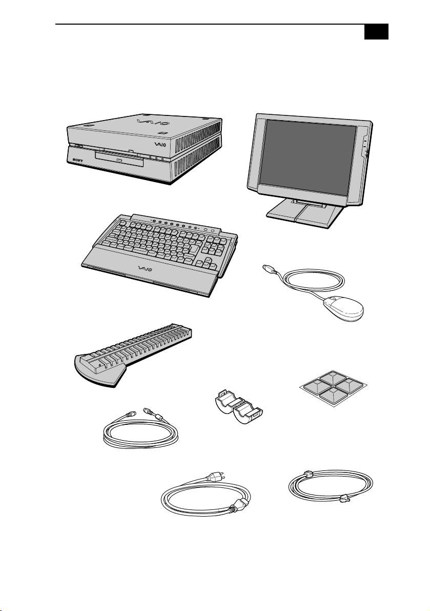
Unpacking Your Computer
Computer and Supplied Accessories
System unit
Keyb oard
Unpacking Your Computer
LCD
3
Mouse
(for vertical installation;
screw is included)
Keyboard cable
Stand
Spacers
Ferrite core
Phone cable
Power cabl e
Page 8

4
VAIO Slimtop LCD Computer User Guide
Manuals
❑
Read Me First contains last-minute supplementary information and
software support numbers.
❑
The VAIO Slimtop LCD Computer User Guide (this manual) contains
features and specifications of your computer. It also includes
information on the applications included with your system and how
to contact software vendors, get started with your computer, and
solve common problems.
❑
The VAIO Consumer Information Guide contains safety and regulatory
information, ergonomic considerations, information on help
resources, and your computer’s limited warranty statement.
❑
The Microsoft® Windows®98 Getting Started manual explains how to
use the basic features of the Windows
®
operating system.
Recovery CDs
❑
System Recovery CD(s) – Enables you to reinstall software that
shipped with your computer if it is corrupted or accidentally erased.
For more information, see “Using the System Recovery CD(s)” on
page 30.
❑
Application Recovery CD(s) – Allows you to reinstall individual
applications or device drivers if they are corrupted or accidentally
erased. For more information, see “Using the Application Recovery
CD(s)” on page 32.
Other
❑
Setting up your VAIO Slimtop LCD Computer (poster)
❑
Packet containing special product offers
Software CDs
❑
Microsoft
®
Works Suite 99 (5-CD set)
Page 9
Locating Controls and Connectors
Locating Controls and Connectors
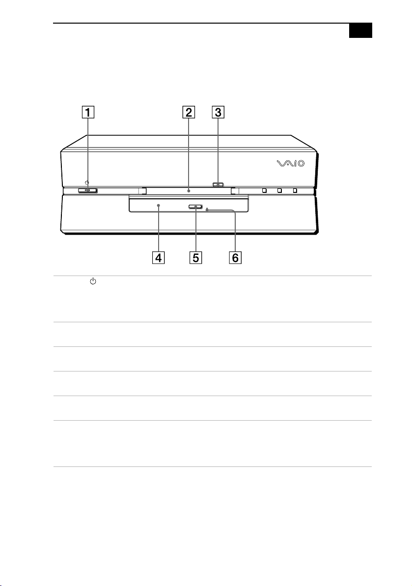
Front Panel
1 Power switch and indicator light
Turns on/off the computer and the display.
The indicator light is green while the power is on, and amber when
the computer is in standby mode.
2 Floppy disk drive
Reads/writes data from/to the 3.5 inch floppy disk.
3 Floppy disk eject button
Ejects the floppy disk.
4 DVD-ROM drive
Reads data from the DVD-ROM/CD-ROM.
5 DVD-ROM/CD-ROM eject button
Ejects the DVD-ROM/CD-ROM.
6 Manual eject hole
If the DVD-ROM/CD-ROM does not come out when you press the
DVD-ROM/CD-ROM eject button, insert a thin, pointed object into
this hole to eject the DVD-ROM/CD-ROM manually.
5
FD DISC HD
Page 10
6
VAIO Slimtop LCD Computer User Guide
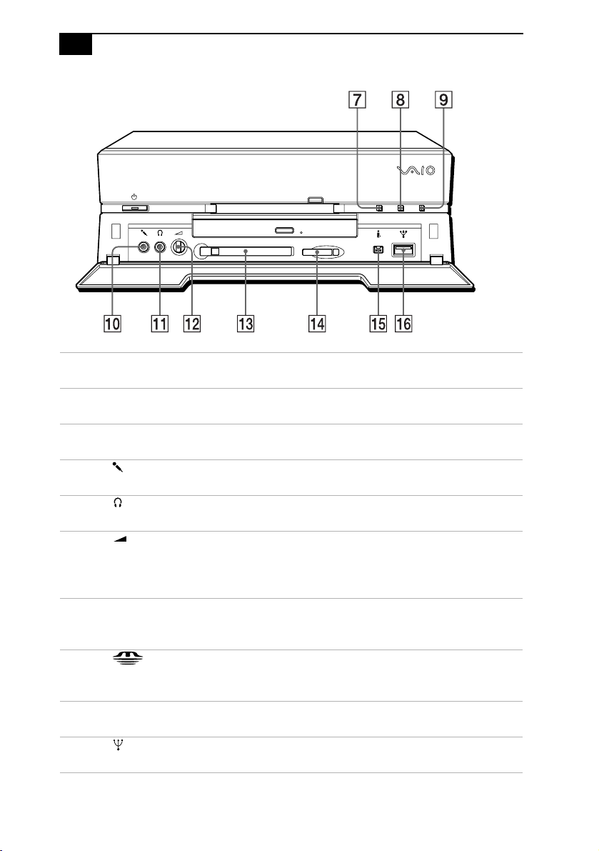
FD DISC HD
7
FD (Floppy disk drive) access indicator light
Lights in green while reading/writing data from/to the floppy disk.
8
Disc (DVD-ROM drive) access indicator light
Lights in amber while reading data from the DVD-ROM/CD-ROM.
9
HD (drive) access indicator light
Lights in green while reading/writing data from/to the hard disk.
0
MIC (Microphone) connector*
Connects a microphone (not supplied).
qa
PHONES (Headphones) connector*
Connects headphones (not supplied).
qs
VOLUME control
Adjusts the volume of the headphones connected to the PHONES
connector. VAIO Slimtop LCD computer users should note that this
does not control the volume of the integrated LCD speakers.
qd
PC CARD slot
A PC Card (also called a PCMCIA card) can be installed in this slot. PC
cards enable you to add functionality to your system.
qf MEMORY STICK
Insert a Sony Memory Stick
using Memory Stick media.
qg
i.LINK (4-pin)
Connects a digital device such as a Sony Digital Handycam Camcorder.
qh
USB (Universal Serial Bus) connector
Connects a USB device.
media slot
™
card into this slot. See for details on
* See “Using a Headphone or Microphone” on page 9 for important information about connecting a
microphone and headphone.
Page 11
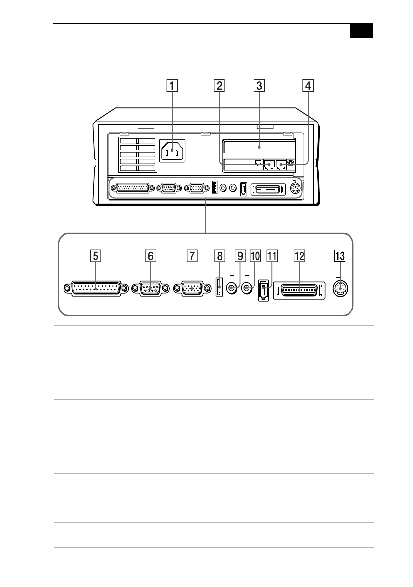
Rear Panel
PRINTER SERIAL MONITOR
Locating Controls and Connectors
LINE PHONE
USB LINE
I.LINK S400
OUTIN
KEYBOARD
LCD
7
PRINTER SERIAL MONITOR
1 AC INPUT connector
Connects the supplied power cord.
2 LINE jack
Connects a phone cable to the wall jack.
3 EMPTY PCI SLOT
For a PCI Add-On Card (not supplied).
4 TELEPHONE jack
Connects the phone to the computer.
5 PRINTER connector
Connects a parallel device such as a printer or scanner.
6 SERIAL connector
Connects a serial device such as a digital still camera.
7 MONITOR connector
Connects a standard CRT display.
8 USB (Universal Serial Bus) connector
Connects a USB device.
9 LINE IN connector
Connects an audio device.
USB LINE
OUTIN
I.LINK S400
LCD KEYBOARD
Page 12

8
VAIO Slimtop LCD Computer User Guide
0 LINE OUT connector
Connects an audio device or an active speaker.
qa i.LINK (6-pin)
Connects a digital device such as a Sony Digital Handycam
Camcorder.
qs LCD MONITOR connector
Connects the LCD that comes with the VAIO Slimtop LCD computer.
Note: Do not connect any display to this connector other than the LCD
that is supplied with this system.
qd KEYBOARD connector
Connects a keyboard.
®
Using the Wheel Mouse
For information about the Wheel Mouse that connects to either side of
your keyboard, see MouseWare Help. To access MouseWare Help, from
the Start menu, point to Programs, MouseWare, and then click
MouseWare Help.
To set up the mouse for left-handed use:
1
Click the My Computer icon on your desktop.
2
Click Control Panel, and then click Mouse. The Mouse Properties
dialog box appears.
3
In the Quick Setup tab, click Device Setup.
4
In the Device Setup Wizard dialog box, click Next.
5
Select the radio button next to “Left side of the keyboard.”
6
Click Next three times, and then click Finish.
7
Click Apply.
Page 13
Locating Controls and Connectors
9
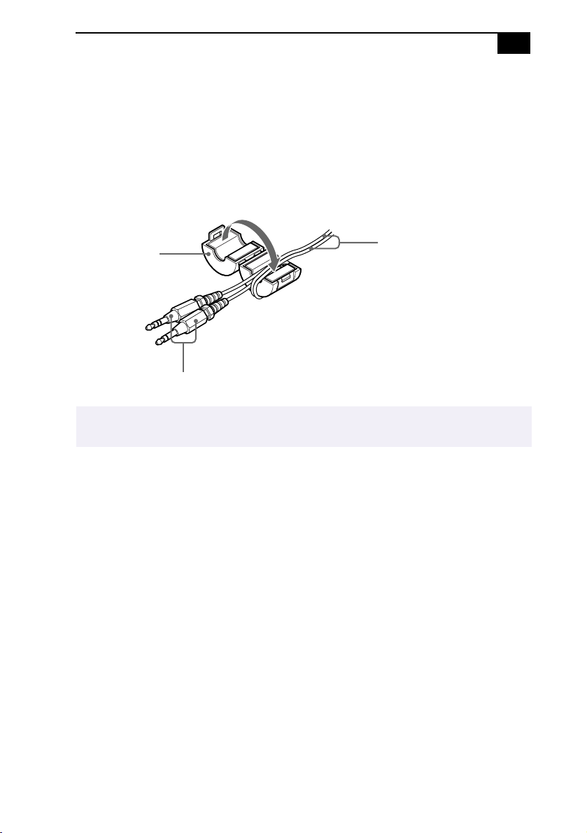
Using a Headphone or Microphone
When you connect a microphone or headphone to your computer,
attaching a ferrite core will reduce electrical interference. Attach the
supplied ferrite core at the end of the headphone or microphone cable
closest to the computer. Wrap the cable through the center of the ferrite
core. The following illustration shows how to attach the ferrite core when
you are using both a headphone and microphone.
Microphone and
Ferrite core
Plugs connected to
the computer
The LCD and keyboard cables already include a ferrite core. Do not remove the ferrite core
✍
from these cables.
headphone cables
Page 14
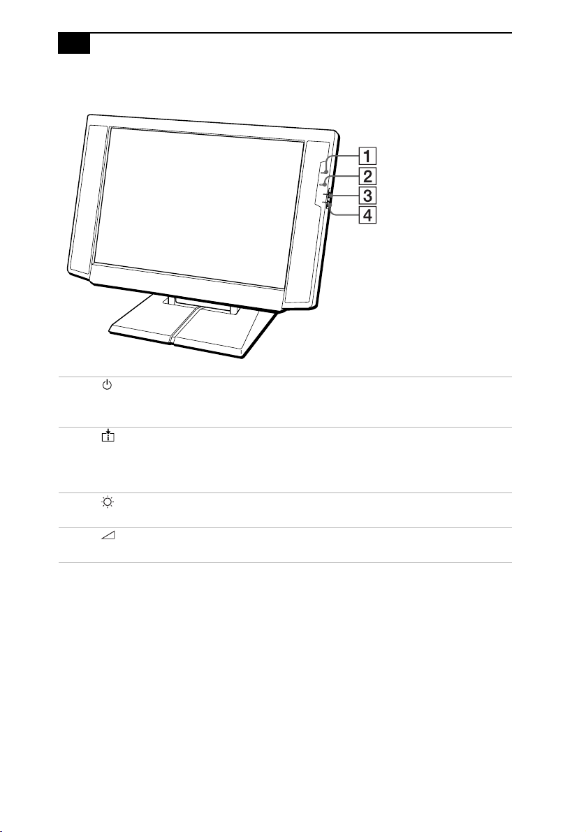
10
VAIO Slimtop LCD Computer User Guide
LCD
1 Power indicator light
Light is green while the power is on. When the computer enters the
standby mode, this indicator light is amber.
2 Information LED
Light turns red to alert the user to activities, such as the arrival of
e-mail. See “Using the AutoAlert E-mail Notification System” on
page 18.
3 Brightness control
Adjusts the brightness of the screen.
4 Volume control
Adjusts the volume of the integrated speakers on the LCD display.
Page 15
Locating Controls and Connectors
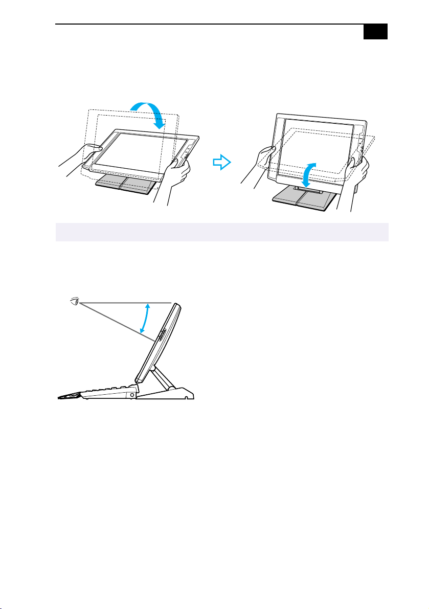
To adjust the height and viewing angle of the display
Holding both sides of the display, push the display panel out and up, and
then adjust the viewing angle.
The LCD display is designed to maintain the best ergonomic viewing angle.
✍
Set the display height so that it does not touch the keyboard, and adjust
the viewing angle approximately 27 degrees from eye level to the center
of the screen.
11
Page 16
12
VAIO Slimtop LCD Computer User Guide
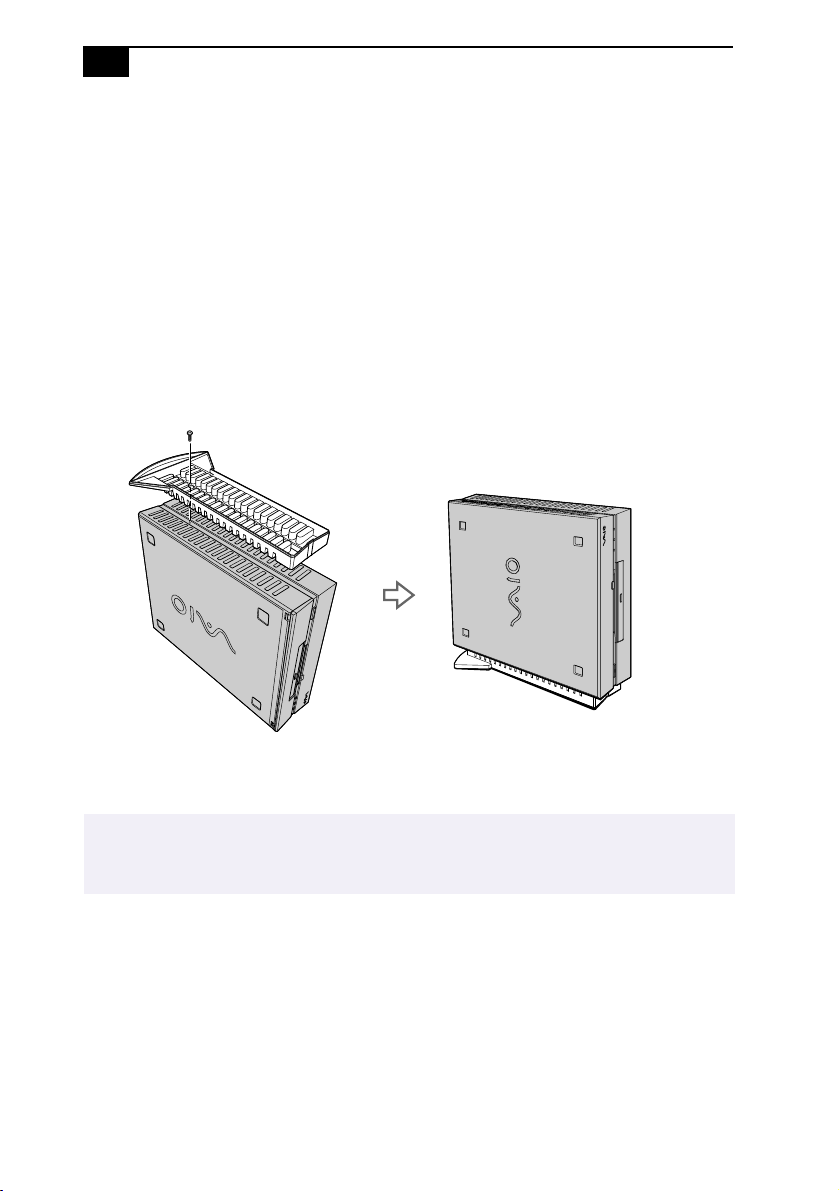
Attaching the Stand to the System Unit
The main system unit can be oriented horizontally or vertically. If you
place the system in a vertical position, you must attach the supplied stand
to ensure stability.
1
Place the system unit on its right side, with the front of the system
facing forward.
2
Insert the grooved side of the stand into the ventilation holes of the
system so that the two screw holes are aligned and the stand’s fins are
at the rear of the unit.
3
Secure the stand to the unit with the supplied screw.
The stand keeps the system cool by allowing air to flow under it. If you choose to place the
✍
system unit in a vertical position, it is important to use the stand and to place the system unit
on its left side, as in the illustration above; otherwise, the system may overheat.
Page 17

Configuring Microsoft® Windows® 98 Second Edition
Configuring Microsoft® Windows® 98
Second Edition
13
The first time you turn on your computer, you need to complete a few
steps to configure the Wi ndows
installed on your computer. You do not need to repeat these steps each
time you turn on your computer.
You must complete the process described below before you can use your computer.
✍
First, ensure that you have a phone cable connected between your
computer and phone jack. Then, follow the on-screen instructions, which
will guide you through the configuration process. The following is an
overview of the process. For details on the benefits of registration, see
“Registering Your Computer” on page 14.
1
Entering information:
❑
Enter your name and follow the online instructions to register.
❑
Read and accept the License Agreement.
❑
Enter your Product ID number located on the cover of the
Microsoft
2
Windows® 98 Second Edition operating system setup: Click the
Finish button on the Windows 98 Setup Wizard screen.
3
Selecting your computer settings: If necessary, change the Time Zone,
Date, and Time on the Date/Time Properties screen.
4
You may sign up for Internet access with a Sony preferred Internet
Service Provider.
®
Windows 98 Getting Started manual.
®
98 operating system that is already
Page 18

14
VAIO Slimtop LCD Computer User Guide
Registering Your Computer
Take advantage of Sony’s commitment to quality customer support and
receive these benefits by registering your computer:
❑
Sony Customer Support—Talk to a Support Representative to
troubleshoot problems you may be having with your computer.
❑
Limited warranty—Protect your investment. See “Limited Warranty
Statement” in the VAIO Consumer Information Guide for details.
You must register your computer to extend the warranty from the initial 90-day warranty
✍
period to one year from the original date of purchase.
❑
Express Service—Provides convenient resolution of problems.
If you did not already register when you first turned on your computer,
follow these steps to use the computer online registration service.
1
Click the registration icon on the VAIO desktop.
2
Enter the information requested on the first online registration form.
Press the Tab key to move from box to box.
3
Click the Next button to advance to the next form.
4
Complete the remaining forms by clicking the Next button each time
you complete a form.
The computer automatically transfers your registration information
using your built-in modem and a toll-free telephone number.
You may sign up for Internet access with a Sony preferred Internet
Service Provider.
Page 19

Using the Programmable Power Keys (PPK)
15
Using the Programmable Power Keys (PPK)
Your Sony computer comes with technology that allows you to get to
your favorite applications easily. Each Programmable Power Key (PPK)
on your VAIO Smart convertible keyboard comes programmed to launch
a preset application with a single press of the key. If you wish, you can
use the PPK Setup software to change the Programmable Power Keys’
preset functions. The PPK Setup software also allows you to set your
computer’s internal timer to launch certain applications automatically.
The Programmable Power Keys are located at the top of your keyboard,
and are numbered P1 through P6. The keys work even when the
computer is turned off. Pressing one turns on the computer and launches
the preset application.
The six Programmable Power Keys come to you preprogrammed to
perform the functions listed in the table below.
Key Function
®
P1 (INTERNET) Starts Microsoft
P2 (MAIL) Starts Microsoft
P3 (WORK) Starts Microsoft
P4 (FINANCE) Starts Intuit® Quicken® Basic 99.
P5 (SETUP) Starts PPK Setup.
P6 (HELP) Opens a menu of help options.
Internet Explorer for Windows® 98.
®
Outlook
®
Works Suite 99
®
98.
Page 20

16
VAIO Slimtop LCD Computer User Guide
Changing the Functions of the Programmable Power Keys
To change the function of a Programmable Power Key:
1
Press the P5 button on the keyboard, or double-click the PPK Setup
icon on the taskbar. The PPK Setup screen appears.
2
Click the Programmable Power Key tab (“PPK1,2,3” or “PPK4,5,6”)
for the Programmable Power Key you want to change.
3
Click the icon showing the key whose function you want to change.
The Assignment screen appears.
4
Select “Change the assigned application” and click Next. The How to
Choose an Application screen appears.
5
Click “Select application from Registered Files list” and then click
Next. The Assign Function screen appears.
Other options on the How to Choose an Application screen include “Register new
✍
application,” “Select Predefined Functions,” and “Create a new Preset Script.” You can
press the Help button to learn more about these options.
6
Select (highlight) an application in the Registered Files column and
then click Finish.
7
The PPK tab appears. Click Apply. The application you have just
selected is now assigned to the Programmable Power Key you chose
in step 3.
8
Click OK to exit PPK Setup.
Page 21

Using the Programmable Power Keys (PPK)
17
Using the Internal Timer
Y ou can use PPK Setup’s internal timer to start an application at a specific
time. The timer can start applications even when the power is off.
1
Press the P5 button on the keyboard, or double-click the PPK Setup
icon on the taskbar. The PPK Setup screen appears.
2
Click the Timer tab.
3
Click the clock icon.
4
If an application is already assigned to the timer, the Assignment
screen appears. Choose “Change the assigned application” and then
click Next.
If no application is currently assigned to the timer, the Assignment
screen does not appear; proceed to step 5.
5
The How to Choose an Application screen appears. Choose “Select
application from Registered Files list” and then click Next.
6
The Assign Function screen appears. Select an application in the
Registered Files column and then click Finish.
7
The Timer tab appears. Click Apply, then click the Set button.
8
The Timer Schedule Setting screen appears.
❑
Select “One time only” if you want the application to launch only
once.
❑
Select “Weekly” if you want the application to start at a certain
time on a regular basis, such as weekly or on certain days of the
week.
Then, click Next.
9
Specify the day and time for the timer to start. Note that the time is in
24-hour format. If you selected “Weekly” in the previous step, you
have the option of specifying more than one day. Then, click Next.
Page 22

18
VAIO Slimtop LCD Computer User Guide
10
The Post Processing screen appears. Entering information on this
screen is optional. If you wish, you can set the computer to shut
down or enter system standby mode after the timer finishes
launching an application. Click the Help button for instructions.
When you have finished, or if you do not wish to choose any options
on the Post Processing screen, click Finish.
11
The Timer tab appears. Click Apply. The timer is now set to launch
the application you selected in step 5.
12
Click OK to exit PPK Setup.
Some software applications take longer than others to launch. It is advisable to confirm in
✍
advance the amount of time your selected application takes to start.
Using the AutoAlert E-mail Notification System
Your VAIO Slimtop LCD computer can be set up to notify you with an
Information LED when new mail arrives in your e-mail mailbox. The
Information LED turns red to indicate that new e-mail has arrived. For
this AutoAlert E-mail Notification System to work, you must use
Microsoft
software, and you must have an Internet Service Provider with dial-up
capabilities set up.
®
Outlook® 98 or Outlook Express as your default e-mail
As an alternative, you can program PPK Setup to set the Information LED
to turn on when PPK Setup has successfully completed the task of dialing
up and connecting to receive mail. In this case, the Information LED turns
on to indicate that your e-mail account has been accessed successfully,
regardless of whether or not you have mail; this works with Netscape
Communicator
Outlook
✍
See “LCD” on page 10 for an illustration showing the Information LED’s
location.
®
The e-mail software you choose to use with PPK must be set as your default e-mail software.
98.
™
4.5, Microsoft® Outlook® Express, and Microsoft®
Page 23

Using the Programmable Power Keys (PPK)
To use the AutoAlert E-mail Notification System
1
Press the P5 button on the keyboard, or double-click the PPK Setup
icon on the taskbar. The PPK Setup screen appears.
2
Click the Registration tab.
3
Click the Preset Script button. The Preset Script Assignment screen
appears.
4
Under “What do you want to do?” select “Get Message” and choose
Outlook 98 Mail Downloading from the drop-down list box. Then,
click Next.
5
The Information LED screen appears. Select “Turn on the Information
LED when new e-mail message has arrived,” then select “MAPI,”
and then click Next.
This only works if you are using Microsoft Outlook 98 or Outlook Express as your default
✍
e-mail software. If you have chosen Netscape Communicator 4.5 instead, you can select
“Turn on the Information LED when process is finished successfully.” This causes the
Information LED to light when PPK Setup has launched your e-mail software and
checked for mail, rather than after it actually downloads your e-mail.
6
The Enter Application Name screen appears. Enter an application
name and description of your choice. For example, you might type
“MyE-mail” as the application name and “Download e-mail” as the
description. Then, click Finish.
19
7
Now you can use either a PPK button or the timer to download your
e-mail. Follow the instructions under “Changing the Functions of the
Programmable Power Keys” on page 16 or “Using the Internal
Timer” on page 17. When you come to the Assign Function screen,
select your newly named application from the Registered Files list.
To turn off the Information LED, click the PPK icon in the Windows®
✍
task tray.
Some e-mail applications are programmed to ask for a password before downloading
mail. If your e-mail software has this feature, PPK may not be able to download your
mail successfully. You can solve this problem by setting your e-mail software to
remember your password rather than prompting you for it.
Page 24

20
VAIO Slimtop LCD Computer User Guide
PPK Setup Software Restrictions
If you use software that uses a phone line
❑
The computer may not be able to disconnect the phone line due to
communication and server conditions.
❑
Be sure to monitor the status of the software when running PPK
Setup, and manually disconnect the phone line if you notice a
malfunction. Furthermore, when using the timer to start the software,
it is advised that you set the computer to shut down or enter system
standby mode after a certain length of time. This allows the computer
to disconnect the phone line if the computer fails to disconnect the
line normally.
If you are using the timer to download e-mail automatically
It is advisable to set up your e-mail software to redial automatically if it
does not connect the first time. It is also advisable to set the e-mail
software to disconnect the phone line automatically when all mail has
been downloaded.
If you are using Microsoft® Outlook® 98
When using the AutoAlert E-mail Notification System with Microsoft
Outlook 98, it is advisable to select the Dial automatically setting in your
Microsoft Outlook 98 software. If you have not chosen this setting and
wish to do so, start Outlook 98, click Tools, and then select Options. Select
the check box “Automatically dial when checking for new messages.”
Click OK.
Page 25

Using the Programmable Power Keys (PPK)
21
Changing the Window Design of Sony Software
To change the window design of Sony software
1
Click the Start button, point to Settings, and then click Control Panel.
2
Click UI Design Selector.
3
Click << or >> and select the desired design.
4
Click Apply.
The “UI Design Selector” window design changes. The window design
for your Sony software will match the “UI Design Selector” window.
To try another selection, click << or >>. Then, click OK.
The UI Design Selector closes and the window design of your Sony
software window design displays.
Note: You may use the feature with UI Design Selector-compatible software only.
✍
Page 26

22
VAIO Slimtop LCD Computer User Guide
Using
Your Sony computer is designed to support the new Memory Stick IC
recording media. The Memory Stick card is a small, versatile device that
allows you to share data between various types of Sony equipment.
✍
If you want to create a slide show that launches automatically when you
insert a Memory Stick, follow these steps to transfer images from your
hard drive to a Memory Stick.
1
Memory Stick
When you use the card, your computer automatically launches Windows Explorer. This allows
you to view the contents of the card.
Insert the card into the card slot.
™ Media
2
Click the My Computer icon on the desktop.
3
Click the Removable Disk S: icon.
4
Create a new folder and name it “DCIM.”
5
Open the DCIM folder and create a new folder named “100MSDCF.”
6
Click the Start button, select VAIO, then click PictureGear to launch
the PictureGear application.
7
Select the digital images you want to save in your slide show.
8
From the PictureGear File menu, point to File Pr ocess, and then select
Still Format Conversion.
9
Select Memory Stick as the Output Format.
10
Use the Browse button to select the DCIM/100MSDCF folder on the
Removable Disk (S:) drive.
11
Click OK to save the file.
Page 27

Using Memory Stick™ Media
You can also add MPEG1 video files to your Slide Show by following the
steps below. Note that the order in which digital still photos (DSC0xxxx
files) and video clips (MOV0xxxx files) appear in your Slide Show is
determined by the number (xxxx) in the file name.
1
Insert the card into the card slot.
2
Click the My Computer icon on the desktop.
3
Click the Removable Disk S: icon.
4
Create a new folder and name it “MSSONY.”
5
Open the MSSONY folder and create a new folder named
“MOML0001.”
6
From the PictureGear File menu, point to File Pr ocess, and then select
Still Format Conversion.
7
Copy the MPEG file into the MOML0001 folder.
8
Rename the MPEG file MOV0xxxx.mpg, where xxxx is any four-digit
number .
9
To begin showing your slides, eject the Memory Stick and then
reinsert it. The slide show will begin automatically.
23
Page 28

24
VAIO Slimtop LCD Computer User Guide
To protect data on Memory Stick media from accidental changes
The Memory Stick card contains a write-protect tab. The write-protect
tab prevents accidental changes to a Memory Stick card. When you slide
the write-protect tab to the LOCK position, the Memory Stick card is
write-protected, which means you cannot delete, copy, or save
information on the Memory Stick card. When you slide the tab to the unLOCK position, you can write to or modify the Memory Stick card
contents.
LOCK
To unlock To lock
LOCK LOCK
To change the way the computer reacts when a Memory Stick card
is inserted into the Memory Stick media slot
Change the options on the Memory Stick tab in the PPK Setup software.
Page 29

Using PC Cards
25
Using PC Cards
This computer has a card bus PC card slot that supports a Type I or II PC
card.
To insert a PC card
You do not need to shut down your computer when inserting a PC card.
✍
1
Open the front panel.
2
Insert the PC card into the PC card slot until it clicks into position.
When the card is completely inserted, the eject button pops out. If you cannot insert the card,
✍
do not forcibly insert it. In this case, make sure the card is not inserted upside-down or
backward, and then reinsert the card into the slot carefully.
See the manual that came with the PC card for details on using it.
To close the front panel when the eject button is protruding, fold the button down onto the
computer.
Page 30

26
VAIO Slimtop LCD Computer User Guide
To eject a PC card
If you eject the PC card incorrectly, the system may not work correctly.
✍
1
Click the Start button on the Windows® taskbar, click Settings, and
then click Control Panel.
2
Click the PC Card icon.
3
Click the name of the card that you want to eject, then click Stop.
4
When the message “You may safely remove this device” appears,
click OK.
5
Push the PC card eject button on the front panel of the system unit.
You may need to pull out the eject button before you can eject the
card.
The card is ejected from the card connector. Remove the card by holding it
by its edge and pulling it out carefully.
Page 31

Using the Standby Function
27
Using the Standby Function
When you are finished using your computer, you can put it in standby
mode rather than turn it off completely. Putting the computer in standby
mode allows you to return quickly to normal computer use.
To put the computer in standby mode manually
1
Save your work and close any applications that are running. (You can
leave Windows running.)
2
Press the (Standby) button on the top of the keyboard.
The computer goes into standby mode.
Alternatively, you can click the Start button on the Windows
click Shut Down, select Standby, and then click OK.
To let the computer go into standby mode automatically
Click the My Computer icon on your desktop. Click Control Panel, and
then click the Power Management icon. On the Power Schemes tab, select
from the options in the Power schemes drop-down list. Then, choose
settings for the power scheme you have selected. To save the settings
under a name that is not offered in the Power schemes pulldown menu,
choose your settings and then click Save As. Type in a name, and click
OK. Click Apply to finalize your power settings.
®
taskbar,
To resume from standby mode
There are three ways to bring your computer back from the standby
mode: press the space bar on your keyboar d, press the left mouse button,
or momentarily depress the power button on your computer.
If the display does not return from standby when you press the (Standby) button, your
✍
system may be in video standby mode. Press the space bar on the keyboard to return from
video standby.
Page 32

28
VAIO Slimtop LCD Computer User Guide
Standby Mode Indicators
You can tell which mode the computer is in by the color of the power
indicator light.
Color Mode
Amber Computer is in standby mode.
Green Computer is out of standby mode, ready to use.
No color Computer is turned off.
In standby mode you may periodically hear the computer’s fan turn on and off, depending on
✍
the room’s temperature. This is normal functioning in standby mode.
Shutting Down Your Computer
When you are ready to turn off your computer for an extended period of
time, use the following procedure to shut down the computer.
!
To avoid the potential loss of data, do not use the power switch to shut down
the computer.
To shut down your computer
If you plan to shut down your computer for a short period of time, you may want to use
✍
standby mode instead. See “Using the Standby Function” on page 27.
1
Click the Start button on the Windows® taskbar to open the Start
menu.
2
Click Shut Down to display the Shut Down Windows dialog box.
3
Select the Shut Down option.
4
Click OK to complete the shutdown process.
Respond to any prompts about saving documents.
✍
5
Wait for your computer to turn off automatically — the power
indicator light turns off.
6
Turn off any peripherals connected to your computer. The LCD
display turns off automatically when the computer shuts down.
Page 33

Shutting Down Your Computer
You can also shut down your computer using the (Power) button on the keyboard.
✍
Pressing this button causes the system to perform a shutdown but does not give you any of
the other options available on the Windows
®
Shut Down menu.
29
About the Power Switch
If your system “locks up” or “crashes,” press and hold the power switch
for four seconds to force your system to power off. You may need to
repeat this procedure. See “Locating Controls and Connectors” on page 5
for the power switch’s location.
Page 34

30
VAIO Slimtop LCD Computer User Guide
Using the System Recovery CD(s)
You can reinstall software titles that shipped with your computer if they
are corrupted or accidentally erased. You may not need to recover the
entire contents of your hard drive. If you experience a problem with your
computer, reinstalling an individual device driver or software title may
correct the problem.
Use the Application Recovery CD(s) to reinstall individual applications
or device drivers. See “Using the Application Recovery CD(s)” on
page 32.
The System Recovery CD(s) contain a backup copy of all the software
originally installed on your hard disk drive. They can be used only to
recover the hard disk of the Sony computer you purchased.
The System Recovery utility gives you three options:
❑
Full Restore without Format restores all the software titles that
originally came with your computer without formatting the hard
disk.
❑
Full Restore with Format formats the hard disk drive and then
restores all the original software. If your hard drive is partitioned into
C and D drives, the computer will offer you the option to reformat
the drive into a single partition.
❑
Operating System Only (Windows 98® Restore with Format) formats
the hard disk drive and restor es the Windows
the device drivers that shipped with your computer. This option is
recommended for advanced users only.
®
operating system and
!
If you choose the Full Restore with Format or Operating System Only option,
your hard disk will be formatted, which removes all the information on the hard
disk drive. You will lose any software you have installed and any other files you
have created since you started to use your computer. This means you will have
to reinstall any applications that were not included with the computer when you
purchased it. If you choose the Full Restore without Format option, you may
need to reinstall applications that were not included with the computer when
you purchased it. If you have any questions on using the System Recovery CD(s),
contact Sony Customer Support.
Page 35

Using the System Recovery CD(s)
To use the System Recovery CD(s)
You need to complete the Windows registration process when you use the System Recovery
✍
CD(s). Make sure you have the product ID number located on the cover of your Microsoft
Windows manual. You will need this number to complete the recovery process.
1
Insert the Sony System Recovery CD in the DVD-ROM drive.
The System Recovery utility boots from the DVD-ROM drive. It must be in the drive when
✍
you turn on the computer.
2
Shut down your computer as described in “Shutting Down Your
Computer” on page 28.
3
Wait 30 seconds and turn on your computer.
4
Click OK to signify you have read and accept the Microsoft End-User
License Agreement.
5
When the System Recovery menu appears, follow the on-screen
instructions to complete the recovery process.
Your system may include one or two System Recovery CDs. If you have two System Recovery
✍
CDs, insert the first CD to run the System Recovery program. You are prompted to insert the
second CD once the information from the first CD has been installed.
The recovery process takes 30 to 60 minutes to complete.
31
Page 36

32
VAIO Slimtop LCD Computer User Guide
Using the Application Recovery CD(s)
The Application Recovery CD(s) allow you to reinstall individual
applications and device drivers if they are corrupted or accidentally
erased. Reinstalling an individual device driver or software title may
correct a problem you are experiencing with your computer, and you may
not need to recover the entire contents of your hard drive. If you do need
to reinstall all the software titles that shipped with your computer, use the
System Recovery CD(s). See “Using the System Recovery CD(s)” on
page 30.
You must be in Windows to run the Application Recovery CD(s). The
application will not run from DOS. If you have any questions on using
the Application Recovery CD(s), contact Sony Customer Support.
To use the Application Recovery CD(s)
1
Turn on your computer. If your computer is already on, close all
applications.
2
When the Windows desktop appears, insert the Sony Application
Recovery CD in the DVD-ROM drive. The Application Recovery
utility loads automatically.
3
When the Application Recovery menu appears, follow the on-screen
instructions to complete the recovery process.
Your system may include one or two Application Recovery CDs. If you have two Application
✍
Recovery CDs, insert the first CD to run the Application Recovery program. You may be
prompted to insert the second CD, depending on the application you wish to restore.
Page 37

About the Software on Your Computer
33
About the Software on Your Computer
Your VAIO Digital Studio computer is ready to help you work, play,
learn, and communicate as soon as you turn it on. This section gives you
an overview of the activities you can perform with your software titles.
For support information, see “For Answers to Your Software Questions”
on page 38.
Adobe Acrobat® Reader
Adobe Systems Incorporated
Acrobat Reader software allows you to view, navigate, and print electronic
documents in Adobe’s Portable Document Format (PDF), an open file format that
is intended to preserve the fidelity of documents created on all major computer
platforms.
®
Adobe PhotoDeluxe
Adobe Systems Incorporated
Create amazing photo effects with PhotoDeluxe. Without learning complex
software, you can enhance, restore, and be creative with your photos. Includes
built-in guided activities, stock photos, clip art, and templates to assist you.
Adobe Premiere® LE
Adobe Systems Incorporated
Adobe Premiere LE offers an interface and editing tool for producing movies
for video, multimedia, or the web. View source clips and edited footage
simultaneously in the monitor window. Create video clips up to three hours long
with complete audio-video synchronization.
Home Edition
America Online
®
America Online
America Online is the world's most popular Internet online service. Stay in touch
with family and friends with Easy-to-Use E-mail, manage your personal finances,
get the latest news and sports scores, and chat with thousands of others who share
your interests.
AT&T WorldNet® Service
AT&T
Fast, reliable Internet access from AT&T WorldNet Service. AT&T WorldNet
Service provides web-based e-mail, a personalized start page from Excite, easy
access to the Excite search engine, free web pages, online and live agent technical
support, instant messaging, and special shopping discounts at Market Square.
Page 38

34
VAIO Slimtop LCD Computer User Guide
CompuServe® 2000
CompuServe Interactive Services
The all new CompuServe 2000 delivers a powerful tool for Internet users who
want serious and timely information, in-depth research, and professional
communities backed by state-of-the-art technologies, including high-speed access
and powerful e-mail messaging.
Digital Media Bar™
Sony Electronics
Media Bar software is your all-in-one solution for audio/video playback. Media
Bar software handles all common computer multimedia formats, and controls
selected Sony devices. Media Bar software encompasses audio/video library
cataloging and playlist management, in addition to digital video quality control
and effects features. Media Bar seamlessly integrates a variety of new media
formats with an easy-to-use software interface.
DVgate™
Sony Electronics
Connect a digital video camera recorder to the i.LINK connector and capture your
own video clips. You can edit the clips from your video, add others, and combine
clips into new movie segments.
EarthLink TotalAccess™
EarthLink Network, Inc.
An Internet Service Provider that supplies access, information, and assistance to
its customers, introducing them to the Internet. Member benefits include e-mail,
newsgroups, a Personal Start Page, a free 6 MB web site, a member magazine, and
24-hour technical support.
eMail inChorus™
Softlink, Inc.
This communications tool turns your e-mail into multimedia e-mail. With
eMail inChorus
™
, in minutes you can send your colleagues and friends
presentations and e-mails narrated with your pre-recor ded voice and
illustrated with graphics and animated annotation.
McAfee’s VirusScan
®
Network Associates, Inc.
Protect your computer from viruses. VirusScan can detect viruses from floppy
disks, Internet downloads, e-mail attachments, intranets, shared files, CD-ROMs,
and online services.
Page 39

About the Software on Your Computer
Microsoft® Encarta® Encyclopedia 99
35
Microsoft Corporation
Microsoft Encarta Encyclopedia combines current, comprehensive content with
up-to-date multimedia technology, providing users with unique, engaging
learning experiences. With the 1999 edition, Encarta provides a wealth of
information resources and unique interactive features.
®
Microsoft
Internet Explorer for Windows® 98
Microsoft Corporation
Internet Explorer delivers the web the way you want it. It's safe, easy to use, and
you can personalize how you access the web. Outlook Express and other tools in
Internet Explorer also help you have a great experience when you are on the web!
Microsoft® Money 99 Basic
Microsoft Corporation
Microsoft Money 99 is personal finance software that lets you perform your
financial tasks, everything from paying bills to planning for the future, in a
smarter, faster way. With Money's online services, you can pay bills and bank
from the comfort of home.
®
Microsoft
Outlook® 98
Microsoft Corporation
Outlook 98 is Microsoft's premier messaging and collaboration client. It combines
the leading support for Internet standards-based messaging systems with
integrated calendar, contact, and task-management features.
Microsoft® Word 97
Microsoft Corporation
The world's leading word processor, allows you to create professional-looking
letters, school reports, and other documents using ready-to-use templates,
automatic formatting, and spelling and grammar checkers.
®
Microsoft
Works 4.5
Microsoft Corporation
Microsoft Works 4.5 is an integrated program for creating spreadsheets,
databases, calendars, and more. The Works Calendar reminds you of important
dates.
Netscape Communicator®
Netscape Communications
Netscape Communicator is the all-in-one Internet tool that makes it easy to
browse the web, send Internet e-mail, chat, read newsgroups, and compose great
web documents.
Page 40

36
VAIO Slimtop LCD Computer User Guide
PictureGear™
Sony Electronics
This image management software displays images from your hard drive, a Sony
digital still camera, or a Sony Mavica
light-table format, so that you can easily view the contents of an entire folder.
Prodigy Internet™
®
camera. The images appear in a convenient
Prodigy Communications Corporation
An Internet service that helps you find what you need online faster and smarter.
Prodigy delivers powerful online content, such as sports scores, stock quotes,
news, and easy access to Excite™, plus a personal e-mail account and quality
customer service, all at a competitive price.
Quicken® Basic 99
Intuit, Inc.
Quicken is the fastest, easiest way to organize your finances. Quicken works just
like your checkbook, so it's easy to learn and use. Quicken manages all of your
finances, bank accounts, credit cards, investments, and loans. You can even pay
your bills online.
Smart Capture
Sony Electronics
Smart Capture is a fun new way to send multimedia messages via e-mail. Smart
Capture manages the i.LINK connection between your computer and a Sony
Digital Handycam
interface. It allows you to capture and compr ess video or still images that you can
save or share via e-mail. A smart solution to computer, digital audio/video, and
network convergence.
®
Camcorder or other cameras that support the i.LINK
Smart Connect
Sony Electronics
Smart Connect allows you to use an i.LINK cable to connect your VAIO computer
to another VAIO computer that supports Smart Connect. You can then use one
computer to copy, delete, and edit files on the other computer. You can also print
from a printer attached to either computer.
Page 41

About the Software on Your Computer
37
Sound Forge
®
Sonic Foundry
Sound Forge allows you to put powerful audio processing tools and effects to
work on your desktop. Simply cut, copy, and paste your way to striking
multimedia files for use in everything from Web pages to desktop presentations.
®
WinFax
Basic Edition
Symantec Corporation
WinFax Basic Edition incorporates an easy-to-use interface that allows you to
send and receive faxes easily. Upgrade to WinFax Pro to receive additional
features.
About Your Recovery CDs
Application Recovery CD(s)
Sony Electronics
The Application Recovery CD program allows you to reinstall individual
applications and device drivers. Use it to restore corrupted or accidentally
erased files.
System Recovery CD(s)
Sony Electronics
The System Recovery CD program allows you to restore the software
titles that shipped with your computer if they become corrupted or are
erased accidentally. It can be used only to restore the hard disk of the
Sony computer you purchased.
Page 42

38
VAIO Slimtop LCD Computer User Guide
For Answers to Your Software Questions
Acrobat® Reader, Adobe PhotoDeluxe® Business Edition
(Adobe Systems Incorporated)
website http://www.adobe.com/
phone 206-628-2746 (fee-based support)
fax 206-628-5737
e-mail techdocs@adobe.com
hours M-F, 6 AM-5 PM PT
America Online
website http://www.aol.com/
phone 800-827-3338
hours 7 days a week, 6 AM - 2 PM ET
AT&T WorldNet® Service (AT&T)
website http://www.worldnet.att.net
phone 800-400-1447
e-mail worldnet@attmail.com
hours 7 days a week, 24 hours a day
CompuServe® 2000 (CompuServe Interactive Services
website http://www.compuserve.com/
phone 800-848-8990
hours M-F, 8 AM - 1 AM ET, S-S 10 AM - 10 PM ET
EarthLink TotalAccess™ (EarthLink Network, Inc.)
website http://help.earthlink.net/techsupport/
phone 800-395-8410
e-mail support@earthlink.net
hours 7 days a week, 24 hours a day
®
(America Online)
)
eMail inChorus™ (Softlink,Inc.)
website http://www.sonk.com
phone 408-970-3370
e-mail support@sonk.com
Page 43

For Answers to Your Software Questions
GTE Easy Sign-up (GTE Internet)
phone 800-927-3000
hours 7 days a week, 24 hours a day
McAfee’s VirusScan (Network Associates, Inc.)
website http://support.mcafee.com
phone 408-988-3832
e-mail cybr@nai.com
hours M - F 9 AM - 5 PM Central Time
39
Mindspring Internet Desktop (MindSpring Enterprises, Inc.)
website http://help.mindspring.com/support
phone 800-719-4660
Quicken® Basic (Intuit Inc.)
website http://www.intuit.com/support
phone 900-555-4688
hours 7 days a week, 24 hours a day
Sound Forge® (Sonic Foundry)
website http://www.sonicfoundry.com/support/
phone 608-256-5555
fax 608-256-7300
e-mail support@sonicfoundry.com
hours M - F, 8 AM - 7 PM CT
WinFax
®
Basic Edition (Symantec Corporation)
website http://www.symantec.com/techsupp/
phone 800-798-0850
fax 800-554-4403 in North America
541-984-2490 outside North America
®
Windows
98 Second Edition Operating System, Works 4.5, Word 97,
Money 99 Basic, Encarta Encyclopedia 99, Internet Explorer 5, Outlook 98
(Microsoft Corporation)
website http://www. sony.com/pcsupport
phone 888-4SONYPC (888-476-6972)
*
hours 7 days a week, 24 hours a day
* Support from 1-888-4SONYPC is free of charge for 90 days after the original date of purchase.
Page 44

40
VAIO Slimtop LCD Computer User Guide
Troubleshooting
This section describes how to solve common problems you may
encounter when using your computer. Many problems have simple
solutions, so try these suggestions before you call Sony Customer
Support.
My computer does not start
❑
Check that the computer is plugged into a power source and that it is
turned on. Check that the power light is lit on the front panel of the
computer.
❑
Confirm that a diskette is not in the diskette drive (unless you are
using a bootable diskette).
❑
Confirm that the power cord and all cables are connected firmly, as
described on the color poster.
❑
If you plugged the computer into a power strip or UPS, make sure the
power strip or UPS is turned on and working.
My computer or software program “locks up”
❑
Close the application that is currently “locked up” by pressing
Ctrl+Alt+Delete. In the Close Program dialog box, scroll down until
you locate “(Not responding)” next to an application. Select this
application and click End Task. Windows attempts to close the
application. If the attempt is unsuccessful, a second dialog box
appears. Select End Task again.
❑
If you are unable to “unlock” the application, repeat the above steps
but select Shut Down when the Close Program dialog box appears.
❑
If the above steps fail to “unlock” your computer, save any unsaved
work, if possible. Press Alt+F4. Select Restart and click OK.
❑
If you cannot restart as described in the preceding steps, you can
restart the computer by pressing Ctrl+Alt+Delete or by pressing the
power switch for more than six seconds.
Pressing Ctrl+Alt+Delete may result in the loss of changes made to files that are
✍
currently open.
❑
Contact the software publisher or designated provider for technical
support. See “For Answers to Your Software Questions” on page 38
for a list of phone numbers and web addresses or see Read Me First.
Page 45

Troubleshooting
My DVD-ROM/CD-ROM drive tray does not open
❑
Make sure the computer is turned on.
❑
If the Eject button does not work, you can open the tray by inserting a
41
straightened heavyweight paper clip into the emergency eject hole.
When I click an application icon, a message such as “You must insert the
application CD into your CD-ROM (DVD-ROM) drive” appears and the
software does not start
❑
Some titles require specific files that are located on the application’s
DVD-ROM/CD-ROM. Insert the disc and try starting the program
again.
❑
Check to make sure you inserted the DVD-ROM/CD-ROM with the
label side facing up.
My modem connection is slow
The computer ’s modem uses K56flex™ technology/V.90. Many factors
influence modem connection speed, including telephone line noise or
compatibility with telephone equipment (such as fax machines or other
modems). If you think your modem is not connecting properly to other
computer-based modems, fax machines, or your Internet Service
Provider, check the following:
❑
Have your phone company check that your phone line is free from
any line noise.
❑
If your problem is fax-related, check that there are no problems with
the fax machine you are calling. The modem that receives your call
may be slower or may use a different communications protocol than
your modem. If this is the case, the connection speed may be slower
than expected.
❑
For optimum performance, ensure you are calling an Internet Se rvice
Provider number that is V.90-compliant.
❑
If you are having a problem connecting with your Internet Service
Provider, check that the ISP is not experiencing technical problems.
❑
If you have a second phone line available, try connecting the modem
to this line.
Page 46

42
VAIO Slimtop LCD Computer User Guide
My modem does not work
❑
Check that the phone line is plugged into the line jack.
❑
Check that the phone line is working. You can check the line by
plugging in an ordinary phone and listening for a dial tone.
❑
Check that the phone number the program is dialing is correct.
❑
Verify that the software you are using is appropriately configured to
recognize and interact with the Sony computer modem. Call the
software publisher if you do not know how to configure the software
to recognize the modem. All programs, preinstalled by Sony, are
compatible.
❑
If you suspect your modem is not functioning, you can perform a
simple test to find out. Click the My Computer icon on your desktop.
Click Control Panel, and the click Modems. Click the Diagnostics tab
and select COM2. Click More Info. If your modem is functioning, a
More Info dialog box will display. If your modem is not functioning,
an error message will appear.
My microphone is too sensitive to background noise
If you find there is too much background noise when you record sound,
you should adjust the microphone gain by following these steps:
1
Right-click the speaker icon (Volume) in the lower-right Windows®
task tray.
2
Click Open Volume Controls. The Volume Control screen appears.
3
In the Options menu, select Properties. The Properties screen
appears.
4
Change the setting for “Adjust volume for” from Playback to
Recording, then click OK.
5
Click the Advanced button under Microphone Balance. The
Advanced Controls for Microphone screen appears.
6
Deselect the check box for 1 Mic Gain (+20dB), then click the Close
button.
7
Close the Recording Control window.
Page 47

Troubleshooting
My mouse does not work
❑
Check that the mouse is plugged into one of the PS/2® connectors on
the keyboard. The other connector connects the keyboard to the
computer.
❑
There may be dust or dirt inside the mouse mechanism. To clean the
mouse, follow these steps:
❑
T urn of f your computer. See “Shutting Down Your Computer” on
page 28 for details.
❑
Remove the mouse ball cover on the back of the mouse by
turning the ring that covers the mouse ball counter-clockwise.
❑
Turn the mouse upright, and drop the mouse ball into your hand.
❑
Using a piece of tape, remove any dust or dirt on the mouse ball
and inside the mouse ball socket.
❑
Return the mouse ball to the socket, and replace the mouse ball
cover. Secure the cover by turning the ring clockwise.
I cannot find the Windows® taskbar
❑
Check that the taskbar is not hidden or shrunken.
❑
Use the mouse to point to the left, right, top, and bottom edge s o f the
screen.
43
See Read Me First for additional information on using your Sony computer.
✍
To Reach Sony
For further assistance, call 1-888-4SONYPC (1-888-476-6972).
Page 48

44
VAIO Slimtop LCD Computer User Guide
Specifications
Model PCV-L620
Processor 500 MHz
Hard Disk Drive 13 GB
Standard SDRAM 128 MB PC-100 SDRAM, expandable to 256 MB
Video RAM 8 MB SGRAM
Graphics 2X AGP 3D graphics hardware acceleration
Sound Capabilities High fidelity 3D PCI audio Aureal AU8810
Diskette Drive 3.5” 1.44 MB FDD
DVD-ROM/CD-ROM Drive 4.8X (max.) DVD-ROM reading
Modem K56flex technology/V.90 compatible
Expansion Capabilities Two PCI slots
Connection Capabilities
(Front)
Connection Capabilities
(Rear)
Connection Capabilities
(Keyboard)
Supplied Accessories Stand (for vertical installation)
24X (max.) CD-ROM reading
PC card (Card bus support)
Memory Stick media slot
left and right connectors
VAIO Smart™ Convertible Keyboard
Spacers (for bottom of the system)
*
Pentium® III
†
Ultra DMA
(ATi Rage LT Pro)
data/fax modem
USB port
Microphone
Headphone
i.LINK (4-pin)
USB port
Modem line (RJ-11)
Phone line (RJ-11)
Parallel (printer)
Serial port
VGA monitor
LCD display
Line In
Line Out
Keyboard
i.LINK (6-pin)
Mouse (PS/2-style)
Power cable
Phone cable
Keyboard cable
PS/2 Wheel Mouse
**
††
Page 49

Specifications
45
Model PCV-L620
Service 90-day limited express service
Limited Warranty 90-day parts/labor standard
Power Requirements 130 watts maximum
Dimensions CPU: 11.2”(w) x 3.6” (h) x 13.4” (d)
Weight CPU: 11.9 lbs. (5.4kg)
Operating Temperature 50º F to 95º F (+10º C to 35º C)
* MHz denotes microprocessor internal clock speed; other factors may affect application performance.
† GB means one billion bytes when referring to hard drive capacity. Accessible capacity may vary.
** Data on a DVD-ROM is read at a variable transfer rate, ranging from 2X at the innermost track to 4.8X at
the outermost track(the data transfer standard 1X rate is 1385 kbytes/s). The average data transfer rate
is 3.6X(4986 kbytes/s). Data on a CD-ROM is read at a variable transfer rate, ranging from 10.5X at the
innermost track to 24X at the outermost track(the data transfer standard 1X rate is 150 kbytes/s). The
average data transfer is 18X(2700 kbytes/s).
†† Maximum speed for faxing is 14.4 kbytes/s. Your modem is capable of downloading at 56 kbytes/s using
K56flex technology or V.90. Your phone service, online service, or Internet Service Provider, however, may
not support this technology or operate at this speed.
***Certain restrictions apply.
Specifications are subject to change without notice.
Extendible to one year from original
date of purchase upon registration
Extendible to one year from original
date of purchase upon registration
(280 mm x 90 mm x 335 mm)
Keyboard: 15.9” (w) x 1.8” (h) x 7.1” (d)
(398 mm x 45 mm x 178 mm)
Display: 16.1” (w) x 13.1” (h) x 6.9” (d)
(403 mm x 327 mm x 172 mm)
Display: 7.05 lbs (3.2 kg)
Keyboard: 2.9 lbs. (1.3kg)
***
††
Page 50

46
Page 51

Index
47
Index
A
AC input connector
Application Recovery CD
AutoAlert E-mail Notification System
18
B
brightness control, on LCD
C
CD-ROM drive
CD-ROM, troubleshooting
cleaning, mouse
computer, troubleshooting
E
eject button, for floppy disk
eject hole, for CD-ROM
F
ferrite core (pictured)
ferrite core, connecting
floppy disk drive
H
headphones connector
9
using
7
32
10
5
41
43
40
5
5
3
9
5
6
line jack
line OUT connector
7
8
M
Memory Stick media
6
slot
22
using
microphone connector
9
using
modem, troubleshooting
monitor connector
6
41
7
mouse
cleaning
troubleshooting
mouse (pictured)
43
43
3
P
PC (PCMCIA) card, using
PC card slot
6
phone cable (pictured)
power cable (pictured)
power indicator
on LCD
10
on system unit
power switch
printer connector
problem solving
5
7
40
Programmable Power Keys (PPK),
15
using
25
3
3
5
I
Information LED, on LCD
K
keyboard
(pictured)
cable (pictured)
connector
3
3
8
L
LCD
(pictured)
adjusting
connector
line IN connector
3
11
8
7
10, 19
R
registering Windows 98
registering your computer
13
14
S
serial connector
software, bundled
software, support contact numbers
spacers (pictured)
stand
(pictured)
attaching
standby mode
System Recovery CD
system unit (pictured)
7
33
3
3
12
27
30
3
38
Page 52

T
telephone jack
troubleshooting
turning on and off the computer
7
40
5, 28, 40
U
Universal Serial Bus (USB) connector
unpacking the computer
unpacking, system (pictured)
3
3
V
volume control for headphones
volume control, on LCD
6
10
W
Windows 98
13
6, 7
48
 Loading...