

Page 1
Page 2
Information in this document is subject to change
without notice.
Sony, VAIO and CLIE are trademarks or
registered trademarks of Sony. Microsoft,
Windows, Windows Media, Outlook, Bookshelf
and other Microsoft products are trademarks or
registered trademarks of Microsoft Corporation
in the United State and other countries.
The word Bluetooth and the Bluetooth logo are
trademarks of
Bluetooth SIG, Inc. AMD, the
AMD logo, other AMD product names and
combinations thereof are trademarks of
Advanced Micro Devices, Inc. Intel Inside logo,
Pentium and Celeron are trademarks or registered
trademarks of Intel Corparation. Transmeta, the
Transmeta logo, Crusoe Processor, the Crusoe
logo and combinations thereof are trademarks of
Transmeta Corporation in the USA and other
countries. Graffiti, Hotsync, PalmModem, and
Palm OS are registered trademarks, and the
Hotsync logo and Palm are trademarks of Palm,
Inc. or its subsidiaries. (M) and Motrola are
trademarks of Motrola, Inc. Other Motrola
pruducts and services with (R) mark like
Dragomball are the trademarks of Motrola, Inc.
All other name of systems, products and services
in this manual are trademarks or registered
trademarks of their respective owners.
In this manual, the (TM) or (R) mark are not
specified.
Caution Markings for Lithium/Ion Battery - The
following or similar texts shall be provided on
battery pack of equipment or in both the
operating and the service instructions.
CAUTION: Danger of explosion if battery is
incorrectly replaced. Replace only with the same
or equivalent type recommended by the
manufacturer. Discard used batteries according
to the manufacturer’s instructions.
CAUTION: The battery pack used in this device
may present a fire or chemical burn hazard if
mistreated. Do not disassemble, heat above
100°C (212°F) or incinerate.
Dispose of used battery promptly.
Keep away from children.
CAUTION: Changing the back up battery.
• Overcharging, short circuiting, reverse
charging, multilation or incineration of the cells
must be avoided to prevent one or more of the
following occurrence; release of toxic materials,
release of hydrogen and/or oxygen gas, rise in
surface temperature.
• If a cell has leaked or vented, it should be
replaced immediately while avoiding to touch
it without any protection.
Service and Inspection Precautions
1. Obey precautionary markings and
instructions
Labels and stamps on the cabinet, chassis, and
components identify areas requiring special
precautions. Be sure to observe these precautions, as
well as all precautions listed in the operating manual
and other associated documents.
2. Use designated parts only
The set’s components possess important safety
characteristics, such as noncombustibility and the
ability to tolerate large voltages. Be sure that
replacement parts possess the same safety
characteristics as the originals. Also remember that
the ! mark, which appears in circuit diagrams and
parts lists, denotes components that have particularly
important safety functions; be extra sure to use only
the designated components.
3. Always follow the original design
when mounting parts and routing
wires
The original layout includes various safety features,
such as inclusion of insulating materials (tubes and
tape) and the mounting of parts above the printer
board. In addition, internal wiring has been routed and
clamped so as to keep it away from hot or high-voltage
parts. When mounting parts or routing wires, therefore,
be sure to duplicate the original layout.
4. Inspect after completing service
After servicing, inspect to make sure that all screws,
components, and wiring have been returned to their
original condition. Also check the area around the repair
location to ensure that repair work has caused no damage,
and confirm safety.
5. When replacing chip components...
Never reuse components. Also remember that the
negative side of tantalum capacitors is easily damaged
by heat.
6. When handling flexible print
boards...
• The temperature of the soldering-iron tip should be
about 270°C.
• Do not apply the tip more than three times to the same
pattern.
• Handle patterns with care; never apply force.
Caution: Remember that hard disk drives are easily
damaged by vibration. Always handle with care.
ATTETION AU COMPOSANT AYANT
LES COMPOSANTS IDENTIFÉS PAR UNE
MARQUE
SCHÉMATIQUES ET LA LISTE DES PIÈCES
SONT CRITIQUES POUR LA SÉCURITÉ DE
FONCTIONNEMENT. NE REMPLACER CES
COMPOSANTS QUE PAR DES PIÈSES SONY
DONT LES NUMÉROS SONT DONNÉSDANS
CE MANUEL OU DANS LES SUPPÉMENTS
PUBLIÉS PAR SONY.
RAPPORT
À LA SÉCURITÉ!
!!
! SUR LES DIAGRAMMES
!!
– 2 –
Confidential
PCG-Z1V/Z1VE/Z1VT (J)
PCG-Z1VAP1/Z1VAP2/Z1VA/Z1VFP (AM)
PCG-Z1VCP/Z1VGP/Z1VJP/Z1VLP/Z1VTP (AO)
Page 3

TABLE OF CONTENTS
Section Title Page
CHAPTER 1. SPECIFICATIONS....................................................... 1-1
(to 1-1)
CHAPTER 2. BLOCK DIAGRAM...................................................... 2-1
(to 2-1)
CHAPTER 3. FRAME HARNESS DIAGRAM .............................. 3-1
(to 3-1)
CHAPTER 4. EXPLODED VIEWS AND PARTS LIST
Palmrest
P-1 ................................................................................................................. 4-2
Bottom
B-1 ................................................................................................................. 4-3
Main Board
M-1 ................................................................................................................ 4-4
LCD
L-1 ................................................................................................................. 4-5
Accessories
A-1 ................................................................................................................. 4-6
DIP Switch .............................................................................................. 4-7
(to 4-7)
CHAPTER 5. OTHERS
5-1. The Barcode Label ..................................................................................... 5-1
5-2. CTO Information ........................................................................................ 5-2
(to 5-2)
1
[MA]
History of the changes is shown as the
Revision History at the end of this data.
– 3 –
Confidential
PCG-Z1V/Z1VE/Z1VT (J)
PCG-Z1VAP1/Z1VAP2/Z1VA/Z1VFP (AM)
PCG-Z1VCP/Z1VGP/Z1VJP/Z1VLP/Z1VTP (AO)
Page 4
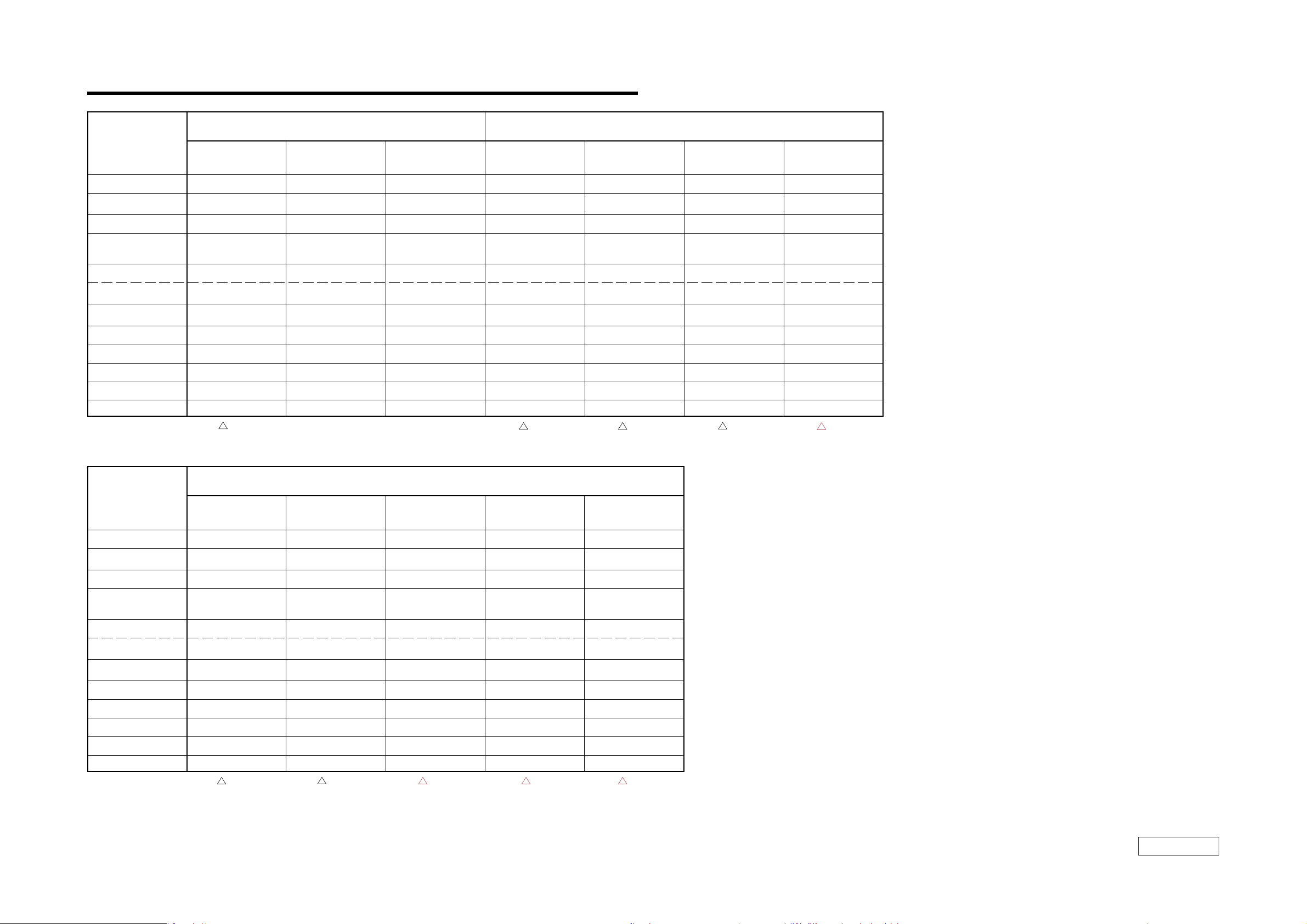
CHAPTER 1.
SPECIFICATIONS
JAM
PCG-Z1VT/P PCG-Z1V/P PCG-Z1VE PCG-Z1VAP1∗ PCG-Z1VAP2∗ PCG-Z1VA∗ PCG-Z1VFP
CPU Pentium-M 1.7 GHz Pentium-M 1.6 GHz Pentium-M 1.3 GHz Pentium-M 1.6 GHz Pentium-M 1.7 GHz Pentium-M 1.6 GHz Pentium-M 1.6 GHz
LCD 14.1SXGA+ 14.1SXGA+ 14.1SXGA+ 14.1SXGA+ 14.1SXGA+ 14.1SXGA+ 14.1SXGA+
HDD 80GB 60GB 40GB 60GB 80GB 60GB 60GB
MEMORY
(STANDARD/MAX) 512 MB/1GB 512 MB/1GB 256 MB/768MB 512 MB/1GB 1GB/1GB 512 MB/1GB 512 MB/1GB
On Board 512MB 512MB 256MB 512MB 512MB 512MB 512MB
SLOT – – – – 512MB – –
OPT-DRIVE COMBO COMBO COMBO COMBO COMBO COMBO COMBO
Wireless LAN aa a aaaa
Bluetooth aa a aaa ✕
AC Adaptor PCGA-AC16V6 PCGA-AC16V6 PCGA-AC16V6 PCGA-AC16V6 PCGA-AC16V6 PCGA-AC16V6 PCGA-AC16V6
Battery PCGA-BP2V PCGA-BP2V PCGA-BP2V PCGA-BP2V PCGA-BP4V PCGA-BP2V PCGA-BP2V
OS XP Professional XP Professional XP Home Edition XP Professional XP Professional XP Home Edition XP Professional
1
[MA]
1
[MA]
1
[MA]
1
[MA]
2
[MA]
AO
PCG-Z1VGP PCG-Z1VLP PCG-Z1VCP PCG-Z1VTP PCG-Z1VJP
CPU Pentium-M 1.6 GHz Pentium-M 1.6 GHz Pentium-M 1.6 GHz Pentium-M 1.6 GHz Pentium-M 1.6 GHz
LCD 14.1SXGA+ 14.1SXGA+ 14.1SXGA+ 14.1SXGA+ 14.1SXGA+
HDD 60GB 60GB 60GB 60GB 60GB
MEMORY
(STANDARD/MAX) 512 MB/1GB 512 MB/1GB 512 MB/1GB 512 MB/1GB 512 MB/1GB
On Board 512MB 512MB 512MB 512MB 512MB
SLOT – – –––
OPT-DRIVE COMBO COMBO COMBO COMBO COMBO
Wireless LAN aa aaa
Bluetooth ✕✕ ✕✕✕
AC Adaptor PCGA-AC16V6 PCGA-AC16V6 PCGA-AC16V6 PCGA-AC16V6 PCGA-AC16V6
Battery PCGA-BP2V PCGA-BP2V PCGA-BP2V PCGA-BP2V PCGA-BP2V
OS XP Professional XP Professional XP Professional XP Professional XP Professional
1
[MA]
1
[MA]
2
[MA]
2
[MA]
2
[MA]
• The trademarks or registered trademarks of above table, refer to page 2.
• The model that is accompanied by astarisk (∗) is CTO model.
•
本表中の商標・登録商標については、2ページをご参照下さい。
•
機種名に(∗ )がつくのは、CTOモデルです。
1–1
(END)
Confidential
PCG-Z1V/Z1VE/Z1VT (J)
PCG-Z1VAP1/Z1VAP2/Z1VA/Z1VFP (AM)
PCG-Z1VCP/Z1VGP/Z1VJP/Z1VLP/Z1VTP (AO)
Page 5
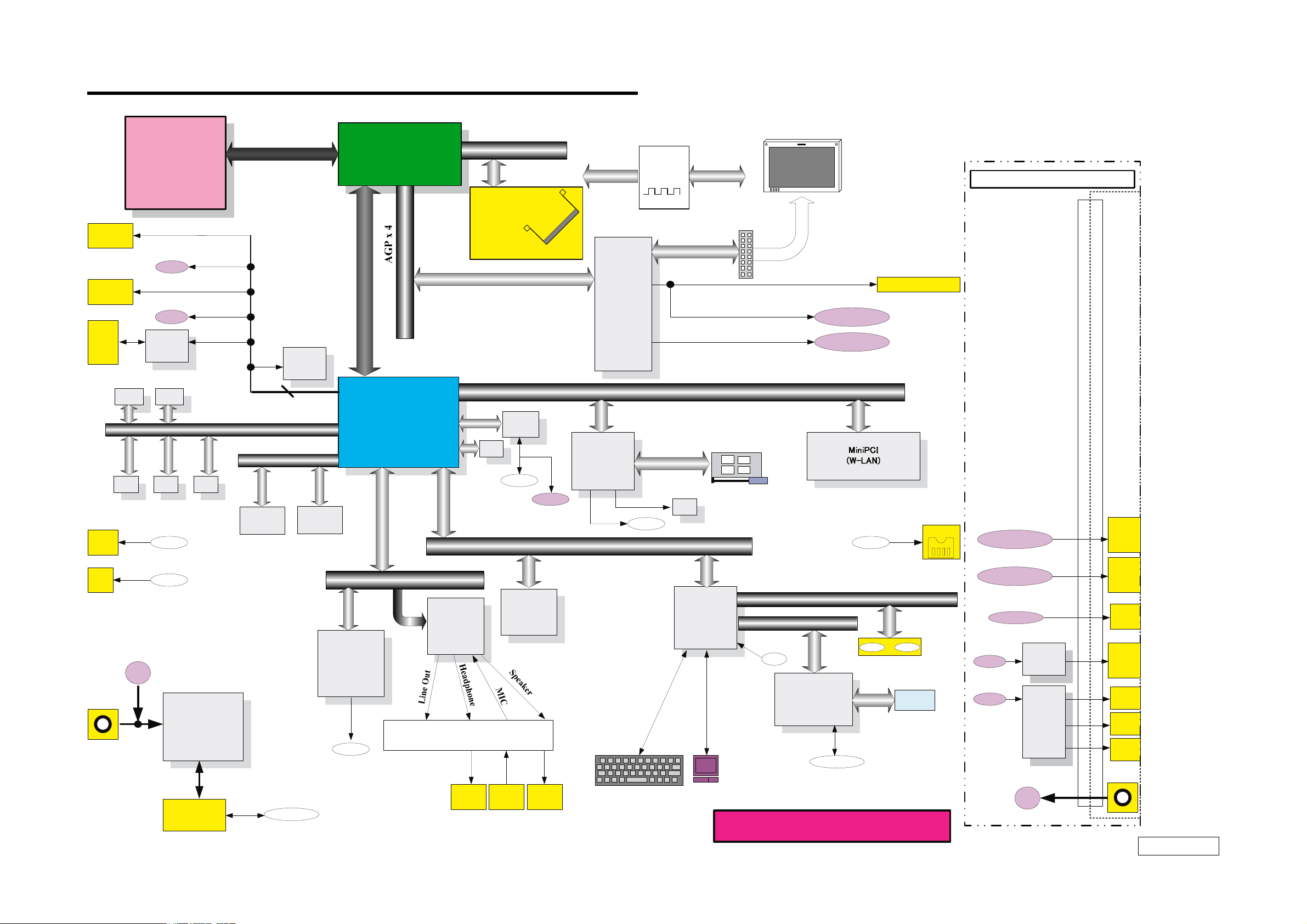
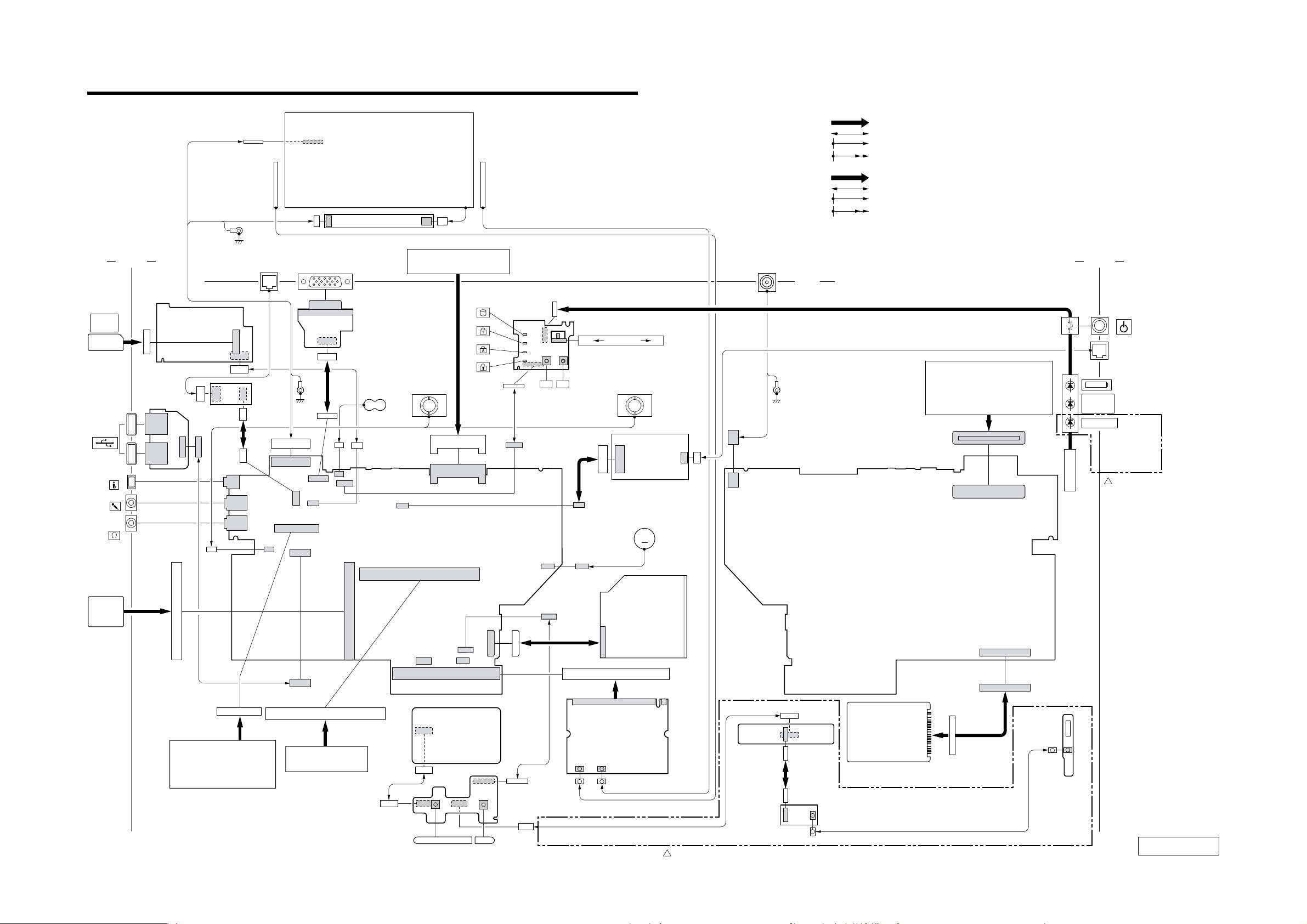
CHAPTER 2.
BLOCK DIAGRAM
USB Left
CONN
USB Left
CONN
MS
CONN
RJ4 5
For SPD
EEP ROM
On DIMM 1
EEP ROM
For VID
Pentium-M
Processor
1MB L2
479pins
uFCBGA
USB1
USB3
Memory
Stick
Module
For SPD
EEP ROM
On DI MM2
EEP ROM
RJ-4 5
EEP ROM
For Passwor d
Port-0
Port-1
Port-2
Port-3
Port-4
SMBUS2
For ClockGEN
CP U Local Bus
Bluetooth
Port-5
Internal
HDD
Module
Port0-5
IDE(A TA100)
Primary
Opt ical
dr ive
Memory
CONT ROL LER
HUB (MCH )
732 FCBGA
IO Control Hub
ICH4-m
421mBGA
Seconda ry
266MHz Memory Bus
(DDR)
On Board
Memory
256MB
or
512MB
SDRAM SO-DIMM
EEP ROM
+
Ether
PHY
For LAN
RJ-4 5
RJ-4 5
LPC
SMBUS2
Gr aphics
M6-C16
(ATI )
CARDBU S
& i.LINK
RICOH
R5C5 51
CL KGEN
ICS
950812YGD
Refer to Clock Gene rator
Block Dia gra m
PCI BUS(3.3V)
CardBus/16bitCa rd
For i.LI NK
EEP ROM
i.LINK0
SMBUS2
L
CD CONN
PC Card
Conne ctor
1 Slot
LCD
SXGA+(14)
SONY
Cable
Dock-VGA DB-15
Dock -DVI
i.LINK0
VGA DSUB-15
i.LINK
Port Repr icator
Dock-DVI
DVI
RJ11
DC Ja ck
DCin
RJ-1 1
Power
Circuit
Batter y
BATTERY 1
MDC
(Mode m
Daughter
Card)
Module
RJ-1 1
AC LINK
Audi o
YMF753
(Yama ha)
AMP, etc.
PHONE
OUT
FW H
8M
(Fla sh BIOS
ROM )
MIC
IN
b
Speaker
L&R
Internal KeyBoar d
Membr ane
2–1
(END)
SMBUS1
H8S/2160
KBC/EC
SPIC
LID
& SM BUS MUX
TouchP ad
SMBUS 0
FA N0 ATF0
I/O Expa nde r
BATTERY 1
SONY CO NFI DENTIAL
Ot her
Cont r ol
Dock-VGA DB-15
RJ-4 5
USB3
USB1
USB=>P RT
PL-2305
USB HUB
UPD720110
DCin
PCG-Z1VCP/Z1VGP/Z1VJP/Z1VLP/Z1VTP (AO)
VGA
DB-15
RJ4 5
PRT
DB-25
USB
CONN
USB
CONN
USB
CONN
DC J ack
1/1
Confidential
PCG-Z1V/Z1VE/Z1VT (J)
PCG-Z1VAP1/Z1VAP2/Z1VA/Z1VFP (AM)
Page 6
MAGIC
GATE
MEMORY
STICK
USB
i LINK
MIC
HEAD
PHONE
Side L
MEMORY STICK
CONNECTOR
110
CN4601
CNX-199
BOARD
SIDE A
LCD HARNESS
IFX-286
BOARD
SIDE A
1414
CN5301
CN5402CN5401
110
1
35
CN4602
9
1
CN5300
CN5400
CN2270
14
WIRELESS
LAN ANT
(L)
NETWORK MONITOR
RJ-45 HARNESS
110
IFX-249
BOARD
SIDE B
8
9
21
89
21
CN1501
4
CN1394
1
3
J2150
2
1
J2250
23
1
1
11
6
1
CN2702
CN721
39
INVERTER UNIT
15
CN5501
10
5
CN5500
15
1
FFC IFX248
FPC
(VGA)
1
15
1012
2
1
CN3902
CHAPTER 3.
FRAME HARNESS DIAGRAM
LCD
UNIT
CNX-200
BOARD
SIDE B
BATTERY
CN2602
9
BATTERY PACK
SPEAKER
L ch
CN4051
8
MBX-71
BOARD
SIDE A
WIRELESS
D6003
D6000
D6001
D6002
CN6000
1
LAN ANT
(R)
SWX-131
BOARD
SIDE A
16
16 2
1
FFC
SWX131
CN2901
115
CN6001
S6002
1
8
OFF WIRELESS ON
P1P2
S6003
FPC (MODEM)
1092
1
CN2001
CN60
2
1
J1
S6003
SPEAKER
R ch
MODEM
DC FAN
MOTOR
CARD
M
From board to connector (direct connection)
Harness (connector at both end)
Harness (soldered at one end)
Connectors soldered on board and appearing on the panel
基板からコネクタへ(ダイレクト接続)
ハーネス(両端がコネクタ付き)
ハーネス(一方が半田付け)
コネクタ(基板側半田付け, パネル側コネクタ)
DC IN 16V
Side R
Rear
FPC (LED-W)
POWER
HARNESS (RJ-11)
MODULAR
JACK
PORT REPLICATOR
PCGA-PRZ1
HARNESS
CN3901
J2
(WITH DC JACK 2P)
1
2
1
2 100
99
CN2701
Wireless
LAN
Bluetooth
PCG-Z1VT/P,
Z1V/P, Z1VE,
Z1VA, Z1VAP1,
Z1VAP2
1
[MA]
MBX-71
BOARD
SIDE B
PC
CARD
PC CARD
CONNECTOR
CN1401
34
68
CABLE ASSY
23
CN2821
24
KEYBOARD
UNIT
10
CN2601
199
1
2
200
CARD MEMORY
(EXPANSION MEMORY)
1
CN801
1
2
FFC
TP
CN5101
12
1
SWX-132
BOARD
SIDE B
CN4501
29 1
30
2
CN4502
TOUCH
PA D
119
20
2
CN2801
14
CN1202
50
2
49
1
2
13
1
FFC SWX132
FPC
(OPT)
124
WIRELESS
CN1601
LAN
CARD
COMBO
DRIVE
1163123
24
CN5600
HDD
CN5601
IFX-250
BOARD
150
FPC (HDD)
CN1202
BLUETOOTH
ANT
SIDE B
14
1
CN5100
CN5102
S5101S5100
1
6
FFC IFX250
J5J6
PCG-Z1VT/P, Z1V/P, Z1VE, Z1VA, Z1VAP1, Z1VAP2
1
[MA]
BLUETOOTH
MODULE
CABLE (WITH U.F.L CONNECTOR)
IFX-251
BOARD
SIDE A
Confidential
PCG-Z1V/Z1VE/Z1VT (J)
PCG-Z1VAP1/Z1VAP2/Z1VA/Z1VFP (AM)
3–1
PCG-Z1VCP/Z1VGP/Z1VJP/Z1VLP/Z1VTP (AO)
(END)
Page 7

CHAPTER 4.
LCD
Palmrest
Bottom
Main Board
[MA]1[MA]1[MA]
1
[MA]
1
[MA]2[MA]
2
[MA]
2
[MA]
2
EXPLODED VIEWS AND PARTS LIST
• The prts list is compiled by blocks of a palmrest and bottom etc.
The sections of the parts list are different depending on the model.
Please refer to list of contents shown in the below.
Section Page
Palmrest
P-1 ...................................................................................................... 4-2
Bottom
B-1 ..................................................................................................... 4-3
Main Board
M-1 ..................................................................................................... 4-4
LCD
L-1 ...................................................................................................... 4-5
Accessories
A-1 ..................................................................................................... 4-6
DIP Switch ............................................................................................ 4-7
分解図と部品表は.パームレスト,ボトムなどのブロックごと
・
に分かれています。機種によって部品表のセクションが異な
りますので,詳細は右下の一覧表を参照してください。
NOTE:
• Items marked “ * ” are not stocked since they are seldom required
for routine service. Some delay should be anticipated when ordering
these items.
• The mechanical parts with no reference number in the exploded
views are not supplied.
• When two or more parts are shown, use the parts described first as
the main part.
• The parts marked “ $ ” are the High Value Modules (HVM).
• The parts marked “ # ” are the parts on which barcode label is
attached.
For the barcode label, refer to CHAPTER 5.
• The parts marked “ & ” are the “Customer Replacable parts (CRP)
” that can be replaced by Field Customer Support.
Especially the parts with the <&> mark require the special attention
to use them. Here fore, check first whether the desired part is one
of the targetted parts of the Customer Replacable Parts (CRP), or
the non-targetted parts by referring to the exploded view.
The components identified by mark ! or
dotted line with mark ! are critical for safety.
Replace only with part number specified.
Les composants identifés par une marque
! sont critiques pour la sécurité.
Ne les remplacer que par une piéce portant
le numéro spécifié.
【使用上の注意】
・
印の部品は常備在庫しておりません。
*
・図面番号のない部品は供給しません。
・併記部品の場合,上部記載部品をメイン部品として使用して
ください。
・部品名称の前に$印のついた部品は,HighValueModule(HVM)
です。
・商品名称の前に#印のついた部品は,バーコードラベル貼付部品
です。
バーコードラベルについてはCHAPTER5を参照してください。
・商品名称の前に&印のついた部品は,お客様窓口などでも交換
可能なCustomerReplacableParts(CRP)です。
特に<&>印のついた部品は,使い分けが必要な部品ですので,
分解図でCoustomerReplacableParts対象部品か.対象外部品か
を必ず御確認ください。
! 印の部品, または! 印付きの点線で囲まれた部品
は, 安全性を維持するために重要な部品です。従っ
て交換時は,必ず指定の部品を使用して下さい。
Palmrest Bottom Main Board LCD Accessoris
Z1VT/P P-1 B-1 M-1 L-1 A-1
J Z1V/P P-1 B-1 M-1 L-1 A-1
Z1VE P-1 B-1 M-1 L-1 A-1
U-CTO P-1 B-1 M-1 L-1 A-1
AM
Z1VFP P-1 B-1 M-1 L-1 A-1
Z1VGP P-1 B-1 M-1 L-1 A-1
Z1VLP P-1 B-1 M-1 L-1 A-1
AO Z1VCP P-1 B-1 M-1 L-1 A-1
Z1VTP P-1 B-1 M-1 L-1 A-1
Z1VJP P-1 B-1 M-1 L-1 A-1
4–1
Confidential
PCG-Z1V/Z1VE/Z1VT (J)
PCG-Z1VAP1/Z1VAP2/Z1VA/Z1VFP (AM)
PCG-Z1VCP/Z1VGP/Z1VJP/Z1VLP/Z1VTP (AO)
Page 8

P-1. Palmrest
[MA]1[MA]1[MA]
1
[MA]1[MA]
1
[MA]1[MA]1[MA]
1
[MA]
2
[MA]2[MA]2[MA]2[MA]
2
[MA]
2
[MA]2[MA]
2
P-1
12
10
14
13
M-1
G
11
B3
15
B4
I
M-1
16
H
M-1
17
18
Ref.No. Part No. Description
31-796-622-11 TOUCH PAD
*4 4-670-302-01 BRACKET (TP)
5 A-8117-905-A $ SWX-132 (3) (S)
61-824-948-11 CABLE, FLEXIBLE FLAT (TP)
*8 4-670-303-01 PLATE (PARM REST L)
9 4-670-975-02 SHEET (TP)
11 4-647-180-01 COIL SPRING
12 1-824-947-11 CABLE, FLEXIBLE FLAT (IFX248)
13 A-8117-909-A $ # IFX-286 (S)
14 4-670-314-01 SHEET (MS)
15 4-670-294-03 ESCUTCHEON (JACK)
18 4-669-735-01 ADHESIVE TAPE (16SH)
19 4-661-451-01 ADHESIVE TAPE TOUCHPAD
20 4-674-011-01 CUSHION (BT)
21 4-675-270-01 SHEET (PW LED)
22 1-824-946-11 CABLE, FLEXIBLE FLAT (SWX131)
23 A-8117-902-A $ SWX-131 (3) (S)
24 1-687-010-12 PWB, FLEXIBLE PRINT (LED-W)
25 4-673-768-01 SHEET (LED B)
*26 4-670-313-02 PLATE (PARM REST R)
Ref.No. Part No. Description
*27 4-670-301-01 BRACKET (OD)
28 1-824-950-11 CABLE, FLEXIBLE FLAT (SWX132)
31 FILAMENT TAPE (W12X30) (*1)
B2 4-673-648-01 SCREW, M2 (+B) (EG)
B3 4-676-936-01 +SCREW, M2 +SPECIAL HEAD SELF S
B16 4-672-834-91 SCRWE, +B EG GRIP
*1 Use the FILAMENT TAPE.
JAM AO
9
F
B-1
PCG-Z1V/T,
Z1V/P, Z1VE,
Z1VA, Z1VAP1,
Z1VAP2
1
[MA]
19
8
E
B-1
7
B
D
M-1
C
26
K
M-1
J
B-1
21
22
6
5
M-1
L
28
B3
31 (*1)
B3
27
20
23
24
B3
25
29
A
4
B2
3
C
2
1
A
B
B2
30
B16
B2
PCG-Z1VT/P, Z1V/P, Z1VE, Z1VA, Z1VAP1, Z1VAP2
1
[MA]
B2
31 (*1)
• This prts list contains two different types of parts.
31 (*1)
• The model that is accompanied by asterisk (∗) is the CTO model.
・
・
Ref. No. Part No. Description
11-234-803-21 BLUETOOTH MODULE
2A-8117-910-A $ IFX-250 (3) (S)
7 1-824-949-11 CABLE, FLEXIBLE FLAT (IFX250)
10 X-4626-401-1 HOUSING (PARM REST) ASSY
X-4626-402-1 HOUSING (PARM REST) ASSY
16 4-678-382-01 LABEL ID
4-678-382-11 LABEL ID
4-678-382-21 LABEL ID
4-678-382-31 LABEL ID
4-678-382-41 LABEL ID
4-678-382-51 LABEL ID
4-678-382-61 LABEL ID
4-678-382-71 LABEL ID
4-679-371-01 LABEL ID
4-679-371-11 LABEL ID
4-679-371-21 LABEL ID
17 1-477-792-11 $ # KEYBOARD UNIT (JP)
1-477-792-21 # KEYBOARD UNIT (US)
1-477-792-81 # KEYBOARD UNIT (LA)
1-477-792-91 # KEYBOARD UNIT (KR)
1-478-193-11 # KEYBOARD UNIT (TW)
1-478-193-21 # KEYBOARD UNIT (TH)
29 A-8117-911-A $ IFX-251 (3) (S)
30 1-827-266-21 CABLE, COAXIAL (WITH U.F.L CONNECTOR)
The fisrt type is the parts is theat are common to all models.
The other type is the parts that are different depending on each model.
この部品表は,機種共通の部品と,機種によって使い分けが必要な部品に分かれています。
機種名に(∗ )がつくのはCTOモデルです。
●●●●●●
●●●●●●
●●●●●●
●●●●●●
●
●●●
●●●●●●
●●●●●●
1
Z1VT/P
●
[MA]
Z1VE
Z1V/P
●
●●
●●● ● ●
1
[MA]
Z1VA ∗
Z1VAP1 ∗
Z1VAP2 ∗
●
1
1
[MA]
[MA]
Z1VCP
●
●
[MA]
Z1VJP
Z1VTP
●
●
2
[MA]
Z1VLP
Z1VFP
Z1VGP
● ●●●●●
●
●
●
●
●
●
2
[MA]
1
[MA]
1
[MA]
2
Confidential
PCG-Z1V/Z1VE/Z1VT (J)
PCG-Z1VAP1/Z1VAP2/Z1VA/Z1VFP (AM)
4–2
PCG-Z1VCP/Z1VGP/Z1VJP/Z1VLP/Z1VTP (AO)
Page 9

B-1. Bottom
[MA]
1
[MA]1[MA]
1
[MA]
2
[MA]
1
[MA]
2
[MA]
2
[MA]
2
[MA]
2
B-1
107
B1
105
104
146
145
PCG-Z1VCP
2
[MA]
B2
108
P-1
B8
147
101
F
103
106
B1
PCG-Z1VCP
2
[MA]
P-1
E
B8
102
146
109
112
M-1
M
R
M-1
148
B2
S
M-1
149
M-1
N
M-1
142 (*1)
B6
Ref.No. Part No. Description
101 4-673-387-01 SHEET (BHF)
102 4-671-053-01 & SHEET (SCREW S)
103 4-670-341-01 & SHEET (SCREW)
104 4-670-340-01 SHEET (BT)
105 4-673-386-01 SPACER (P)
* 106 4-670-328-01 BRACKET (HDR)
M-1
U
112
B2
115
114
116
143 (*2)
B2
112
V
* 108 4-670-327-01 BRACKET (HDL)
109 4-672-493-01 COVER (SC)
110 4-670-319-01 COVER (PR)
*111 4-670-333-01 LOCK (PR)
112 4-662-881-02 CUSHION, KEY BOARD
113 1-825-310-12 SPEAKER, BOX WITH (2.3CM)
M-1
T
113
B2
B10
114 4-675-315-01 SHEET (K1035)
115 1-761-606-14 CARD, MODEM
1161-687-012-11 PWB, FLEXIBLE PRINT (MODEM)
117 4-672-491-01 SHEET (FIN)
1181-400-255-11 FERRITE CORE
119 4-674-429-01 THERMAL PAD (GFX)
120 4-670-320-01 SHEET (MDC)
121 4-670-345-03 COVER (HINGE)
122 4-670-322-04 BASE, DISPLAY
124 4-671-461-01 TAPE (M)
125 4-671-235-01 SHEET (M)
126 1-962-037-11 HARNESS (RJ11)
127 1-687-011-11 PWB, FLEXIBLE PRINT (OPT)
* 128 4-670-346-01 BRACKET (ODR)
129 X-4625-673-2 BEZEL (ODP) ASSY
130 1-796-626-12 $ # COMBO DRIVE (UJDA745, 9.5MM)
* 131 4-670-330-01 BRACKET (ODL)
132 4-670-318-03 COVER (BT)
Ref. No. Part No. Description
107 A-8067-943-A $ # ASSY HDD 80GB (I. 40) (S)
A-8111-360-A $ # ASSY HDD 60GB (T. 30) (S)
A-8116-402-A $ # ASSY HDD 60GB (I. 40) (S)
A-8116-404-A $ # ASSY HDD 40GB (I. 40) (S)
123 1-761-660-13 CARD, WIRELESS LAN (CLX11B 11CH)
1-761-660-23 CARD, WIRELESS LAN (CLX11B 14CH)
1-761-784-11 CARD, WIRELESS LAN
144 4-674-985-01 SHEET (MINI-PCI)
145 4-679-415-01 PLATE (UL) 1
146 4-676-302-01 TAPE (COMMON)
147 4-679-417-01 SPACER (UL) 1
148 4-679-416-01 PLATE (UL) 2
149 4-679-418-01 SPACER (UL) 2
122
B13
125
B2
X
M-1
112
121
B2
131
127
117
130
112
124
126
128
B10
123
144
PCG-Z1VT/P,
Z1V/P, Z1VE
1
[MA]
B13
Y
129
B9
F
111
112
110
M-1
Q
M-1
P
B3
O
M-1
G
M-1
H
E
119
109
M-1
I
120
B3
142 (*1)
Y
P-1
J
M-1
W
Z
118
B
O
M-1
V
141
M-1
B6
142 (*1)
133
B16
M-1
142 (*1)
C
B2
B16
138
138
B7
133
139
140
135
B6
134
M-1
A
114
B10
Z
B9
D
M-1
Ref.No. Part No. Description
133 4-670-335-02 LEVER, RELEASE
134 4-671-074-01 LABEL (DOOR IO)
135 4-635-956-01 SPRING (B), COMPRESSION COIL
136 4-670-338-02 KNOB (BR)
137 4-670-336-02 KNOB (BL)
138 4-670-325-01 & FOOT
139 X-4625-671-2 DOOR (IO) ASSY
140 4-670-324-03 # HOUSING (BOTTOM)
141 4-673-385-01 SHEET (GP)
142 FILAMENT TAPE (W12X30) (*1)
143 CAPTON TAPE (W10X20) (*2)
B1 4-672-839-01 HEAD, M3 FLAT
B2 4-673-648-01 GRIP, M2 (+B) (EG)
B3 4-676-936-01 +SCREW, M2 +SPECIAL HEAD SELF S
B6 4-672-834-61 & SCREW, +B EG GRIP
B7 4-672-834-81 & SCREW, +B EG GRIP
B8 4-672-834-51 & SCREW, +B EG GRIP
B9 4-673-646-01 DIA. (4.6) (M2)
B10 4-673-647-01 M2 (+BSW)
B13 4-671-538-01 SCREW (M2X4), SPECIAL HEAD
B16 4-672-834-91 & SCRWE, +B EG GRIP
*1 Use the FILAMENT TAPE.
*2 Use the CAPTON TAPE.
JAM AO
Z1VE
Z1V/P
Z1VT/P
Z1VA ∗
Z1VAP1 ∗
Z1VAP2 ∗
●●
●●●● ● ●●
●
●●●●●
●●●
●●●
1
1
2
1
Z1VLP
Z1VFP
Z1VGP
Z1VTP
Z1VCP
● ●
●●●●
●
●
●
●
●
2
1
Z1VJP
2
137
136
132
• This prts list contains two different types of parts.
The fisrt type is the parts is theat are common to all models.
The other type is the parts that are different depending on each model.
• The model that is accompanied by asterisk (∗) is the CTO model.
この部品表は,機種共通の部品と,機種によって使い分けが必要な部品に分かれています。
・
機種名に(∗ )がつくのはCTOモデルです。
・
4–3
[MA]
[MA]
[MA]1[MA]
[MA]
[MA]1[MA]
[MA]2[MA]
[MA]
Confidential
PCG-Z1VAP1/Z1VAP2/Z1VA/Z1VFP (AM)
PCG-Z1VCP/Z1VGP/Z1VJP/Z1VLP/Z1VTP (AO)
PCG-Z1V/Z1VE/Z1VT (J)
Page 10

M-1. Main Board
[MA]
1
[MA]
1
M-1
206
R
B-1
1
[MA]
PCG-Z1VAP2
207
239
208
M
B-1
A
B-1
204
B2
212
209
B-1
T
205
B9
213
P-1
D
210
N
B-1
213
211
202
B-1
I
J
B-1
S
B-1
F
201
203
214
P-1
G
P-1
P-1
L
C
238
215
K
B-1
B2
216
B-1
B6
B6
W
K
B12
B12
J
217
P-1
H
219
H
B-1
U
B6
220
B-1
205
218
B2
B2
B6
236
I
B-1
226
237
224
225
234
B8
P
B-1
235
221
K
227
204
B-1
234
E
B2
L
Q
B-1
B-1
D
204
204
222
205
233
228
223
B8
L
B2
B
B-1
B-1
X
G
B-1
230
232
229
205
231
B11
B2
Ref.No. Part No. Description
* 201 4-670-289-01 HEAT SPREADER
202 4-671-078-01 SHEET (MEMO), THERMAL
203 4-671-187-01 SHEET (HS)
204 4-662-881-02 CUSHION, KEY BOARD
205 4-672-493-01 COVER (SC)
206 1-687-009-11 PWB, FLEXIBLE PRINT (HDD)
208 4-670-342-01 SHEET (PR)
209 4-670-321-01 SHEET (PCC)
210 1-694-760-21 JACK, SMALL TYPE
211 1-694-760-31 JACK, SMALL TYPE
212 1-817-281-14 CONNECTOR, PC CARD
213 4-670-343-01 SPACER (ETHER)
214 A-8117-906-A $ IFX-249 (3) (S)
215 1-962-080-11 HARNESS, RJ-45
216 4-671-235-01 SHEET (M)
217 A-8117-907-A $ CNX-199 (3) (S)
218 1-794-548-21 CONNECTOR, USB (A)
219 1-824-973-11 CABLE ASSY
* 220 4-670-331-01 BRACKET (USB)
221 1-687-013-12 PWB, FLEXIBLE PRINT (VGA)
222 A-8117-908-A $ # CNX-200 (3) (S)
* 223 4-670-329-01 BRACKET (IO)
224 1-756-038-11 BATTERY, NICKEL HYDROGEN
225 4-642-711-01 SHEET (BATTERY), ADHESIVE
226 4-674-010-01 THERMALPAD (MCH)
227 4-673-971-02 SHEET (CPU)
228 4-672-944-01 THERMAL SHEET (CPU)
229 4-672-945-01 GUARD (FIN)
230 1-763-964-12 DC FAN
* 231 4-670-332-02 HOLDER (DC)
Ref. No. Part No. Description
207 A-8117-897-A $ # MBX-71 (B3) (S)
A-8117-899-A $ # MBX-71 (C3) (S)
A-8117-900-A $ # MBX-71 (D3) (S)
239 A-8067-880-A $ # COMPLETE PWB MM-10
• This prts list contains two different types of parts.
Ref.No. Part No. Description
232 4-674-795-01 SHEET (DC)
233 1-961-978-12 HARMESS (WITH DC JACK 2P)
234 4-673-671-01 THERMALPAD (FET)
235 4-673-670-01 THERMALPAD (COIL)
236 4-671-186-01 SHEET (BFAN)
* 237 4-670-291-01 BRACKET (FAN)
238 4-671-077-01 SHEET (GFX), THERMAL
B2 4-673-648-01 GRIP, M2 (+B) (EG)
B6 4-672-834-61 SCREW, +B EG GRIP
B8 4-672-834-51 SCREW, +B EG GRIP
B9 4-673-646-01 DIA. (4.6) (M2)
B11 4-635-966-01 SCREW (HEX)
B12 4-673-751-01 NUT (M2) (TYPE2)
The fisrt type is the parts is theat are common to all models.
The other type is the parts that are different depending on each model.
• The model that is accompanied by asterisk (∗) is the CTO model.
この部品表は,機種共通の部品と,機種によって使い分けが必要な部品に分かれています。
・
機種名に(∗ )がつくのはCTOモデルです。
・
J AM AO
Z1VE
Z1V/P
Z1VT/P
●●
●●●● ●●●●●
●
1
[MA]
Z1VAP1 ∗
Z1VAP2 ∗
●
1
[MA]1[MA]
Z1VA ∗
1
[MA]
2
Z1VFP
1
[MA]
Z1VGP
1
[MA]
Z1VLP
Z1VCP
[MA]2[MA]2[MA]
[MA]
Z1VJP
Z1VTP
2
4–4
Confidential
PCG-Z1V/Z1VE/Z1VT (J)
PCG-Z1VAP1/Z1VAP2/Z1VA/Z1VFP (AM)
PCG-Z1VCP/Z1VGP/Z1VJP/Z1VLP/Z1VTP (AO)
Page 11

L-1. LCD 14-inch SXGA+
305
B16
B2
304
B8
303
319
B2
B4
321
- Made by TS -
323 (*2)
306
P
307
B2
B2
315
N
O
B16
316
313
M
308
312
P
314
322
311
309
310
B3
L-1
Ref.No. Part No. Description
301 X-4625-667-3 HOUSING (BEZEL) ASSY
302 4-671-221-02 & CAP (DOWN)
303 4-670-189-01 & CUSHION (UP)
304 1-754-292-12 ANTENNA (2.4GHZ L AND R)
305 4-669-620-03 HINGE (L)
306 A-8114-655-A $ # LCD (UNIT) (14SXGA+) (S)
307 4-669-613-02 COVER (WLL)
308 A-8114-751-A DISPLAY ASSY (S)
309 4-669-615-03 COVER (DISPLAY)
310 4-669-622-01 MAGNET
311 4-669-614-02 COVER (WLR)
312 4-669-612-02 COVER (CABLE)
313 1-477-753-11 INVERTER UNIT
314 4-675-311-01 SHEET (WLCL)
315 4-673-641-01 SHEET (CORNER)
316 4-669-621-02 HINGE (R)
317 4-671-222-01 SHEET (LH)
318 1-961-999-21 HARNESS, LCD (SXGA+)
319 4-670-188-01 & CUSHION (CENTER)
320 4-670-190-01 & CUSHION (SIDE)
302
B8
301
320
M
318
B2
N
O
317
321
B4
321 4-675-342-01 SHEET (HIS)
322 4-675-312-01 ADHESIVE TAPE (WLCL)
323 CAPTON TAPE (W10X30) (*2)
B2 4-673-648-01 SCREW, M2 (+B) (EG)
B3 4-676-936-01 +SCREW, M2 +SPECIAL HEAD SELF S
B4 4-672-834-71 SCREW, +B EG GRIP
B8 4-672-834-51 & SCREW, +B EG GRIP
B16 4-672-834-91 SCREW, +B EG GRIP
*2 Use the CAPTON TAPE.
4–5
Confidential
PCG-Z1V/Z1VE/Z1VT (J)
PCG-Z1VAP1/Z1VAP2/Z1VA/Z1VFP (AM)
PCG-Z1VCP/Z1VGP/Z1VJP/Z1VLP/Z1VTP (AO)
Page 12

A-1. Accessories
[MA]1[MA]1[MA]
1
[MA]
1
[MA]1[MA]
1
[MA]
1
[MA]1[MA]
1
[MA]1[MA]
1
[MA]
2
[MA]2[MA]2[MA]2[MA]
2
A-1
1
[MA]
801
AC Adaptor
802
Power Cord
803
Battery Pack
804
Power Coard
1
[MA]
809
Battery Pack
Ref.No. Part No. Description
! 801 1-477-749-51 $ & ADAPTOR, AC
Ref. No. Part No. Description
!802 1-782-476-22 & CORD, POWER
1-790-732-32 & CORD, POWER
803 A-8114-136-A $ & BP2V (J) ASSY (S)
A-8114-137-A $ & BP2V (U) ASSY (S)
1-756-328-22 $ & BATTERY PACK, LITHIUM ION (PCGA-BP2V)
!804 1-757-562-21 & CORD, POWER
!805 1-555-074-31 & CORD, POWER
!806 1-575-131-61 & CORD, POWER
!807 1-823-947-32 & POWER-SUPPLY CORD
!808 1-770-019-12 & ADAPTOR, CONVERSION PLUG 3P
809 A-8114-139-A $ & BP4V (U) ASSY (S)
—4-679-331-01 & QUICK START, 2800UA
—4-679-384-01 & INSTRUCTION MANUAL (XP Professional, XP Home Edition)
— 4-679-642-11 & SPEC SHEET, 2800LA
— 4-679-643-11 & QUICK START, 2800LA
— 4-679-658-11 & INSTRUCTION MANUAL (XP Professional)
—4-679-658-21 & INSTRUCTION MANUAL (XP Professional)
—4-679-658-41 & INSTRUCTION MANUAL (XP Professional)
—4-679-659-31 & INSTRUCTION MANUAL (XP Professional)
J AM AO
Z1VE
Z1V/P
Z1VT/P
●●●
●●●
●●●
1
Z1VAP1 ∗
●●●
●●●●●
●
●●●
1
1
Z1VFP
Z1VA ∗
Z1VAP2 ∗
●
●
2
1
Z1VTP
Z1VCP
●
2
Z1VJP
2
Z1VLP
Z1VGP
●
●●●●●
●
● ●
●
●
● ●
●
●
1
1
1
1
1
1
[MA]
805
Power Coard
[MA]
806
Power Coard
[MA]
807
Power Coard
[MA]
808
Adaptor Conversion
Plug 3P
• This prts list contains two different types of parts.
The fisrt type is the parts is theat are common to all models.
The other type is the parts that are different depending on each model.
• The model that is accompanied by asterisk (∗) is the CTO model.
この部品表は,機種共通の部品と,機種によって使い分けが必要な部品に分かれています。
・
機種名に(∗ )がつくのはCTOモデルです。
・
[MA]
[MA]
[MA]
[MA]
[MA]
[MA]
[MA]
[MA]2[MA]
[MA]
4–6
Confidential
PCG-Z1V/Z1VE/Z1VT (J)
PCG-Z1VAP1/Z1VAP2/Z1VA/Z1VFP (AM)
PCG-Z1VCP/Z1VGP/Z1VJP/Z1VLP/Z1VTP (AO)
Page 13

DIP Switch
The DIP switch setting is following table.
DIPスイッチの設定は下の表をご覧ください
Set the DIP switch on the MBX-71 board (Main board) to match with the LCD that is used in this computer.
MBX-71 Board(メインボード)のDIPスイッチは,下図のように本機で使用するLCDに合わせて設定します。
1
2
3
4
ON
The lower position where ON indication is shown is the ON position.
The upper position is the OFF position.
下側(ONと表記のある側)がON,上側がOFF
No.
1234
ON/OFF
1011
0 : ON 1: OFF
4–7
(END)
Confidential
PCG-Z1V/Z1VE/Z1VT (J)
PCG-Z1VAP1/Z1VAP2/Z1VA/Z1VFP (AM)
PCG-Z1VCP/Z1VGP/Z1VJP/Z1VLP/Z1VTP (AO)
Page 14

5-1. The Barcode Label
The half-tone dot meshing part will be used as repair data.
バーコードラベルの網掛け部は,修理データとして使用いたします。
CHAPTER 5.
OTHERS
[ Main Section ] (Bottom) [ COMBO Drive ] (Top)
B
E
E
[ MBX-71 Board ] (Side A)
[ LCD ] (Bottom)
[ HDD ] (Top)
E
A, B
A, B
E
GCF
[ IFX-286 Board ] (Side B)
A, B
A, B
[ KEYBOARD ] (Bottom)
A:PartNo.
C
A, B
B:SerialNo.
C:RevisionNo.
D:ProductCode
E:MakerBarcode
F:GlobalUserID(iLink)
G:MacAddress
:Barcode
Confidential
PCG-Z1V/Z1VE/Z1VT (J)
5–1
PCG-Z1VAP1/Z1VAP2/Z1VA/Z1VFP (AM)
PCG-Z1VCP/Z1VGP/Z1VJP/Z1VLP/Z1VTP (AO)
Page 15

5-2. CTO Information
(
)
(
)
1. PCG-Z1VA/Z1VAP1/Z1VAP2
1
[MA]
PCG-Z1V Series CTO Component List
Ver.1.0
Configuration Parts
M/B
HDD
LCD
Expansion Memory
Battery
Opt.Drive
W-LAN
Bluetooth
Office
OS
MBX-71 (B3) (S)
MBX-71 (C3) (S)
80GB
60GB
14SXGA+ A-8114-655-A
512MB A-8067-880-A
BP2V
BP4V A-8114-139-A
COMBO DRIVE 1-796-626-12
Available 1-761-660-13
Available Bundle WinXP Pro
WinXP Home
CPU:1.7Ghz/Memory (On-Board):512MB
CPU 1.6Ghz/Memory (On-Board):512MB
Product Code
Model Name
A-8117-897-A
A-8117-899-A
A-8067-943-A
A-8116-402-A
A-8114-137-A
-
-
The parts marked " " are commonly used in all models. For the component of the
parts that are not shown here, please refer to the PCG-Z1V* Service Manual.
28156630 28156530 28156930
PCG-Z1VA PCG-Z1VAP1 PCG-Z1VAP2
-
-
-
--
a
-
aa
-
aa
aa
-
aa
a
-
a
-
a
a
-
a
aaa
aaa
a
a
-
--
-
--
aa
aa
Confidential
5–2
(END)
PCG-Z1VAP1/Z1VAP2/Z1VA/Z1VFP (AM)
PCG-Z1VCP/Z1VGP/Z1VJP/Z1VLP/Z1VTP (AO)
PCG-Z1V/Z1VE/Z1VT (J)
Page 16

PCG-Z1V/Z1VE/Z1VT (J)
PCG-Z1VAP1/Z1VAP2/Z1VA/Z1VFP (AM)
PCG-Z1VCP/Z1VGP/Z1VJP/Z1VLP/Z1VTP (AO)
List of PCG-Z1 Series (As of October, 2003)
Service Manual
Parts No.
9-876-075-XX
9-876-076-XX PCG-Z1A
9-876-078-XX PCG-Z1FP
9-876-077-XX PCG-Z1MP
9-876-079-XX PCG-Z1GP
9-876-080-XX PCG-Z1LP
9-876-331-XX
9-876-339-XX PCG-Z1RA
9-876-340-XX
9-876-332-XX PCG-Z1RGP
9-876-333-XX PCG-Z1RLP
9-876-335-XX PCG-Z1RCP
9-876-334-XX PCG-Z1RTP
9-876-345-XX PCG-Z1V/P PCG-Z1VAP2 ∗ PCG-Z1VLP
JAMEUAO
PCG-Z1/P
PCG-Z1T/P
PCG-Z1R/P
PCG-Z1RT/P
PCG-Z1VT/P PCG-Z1VAP1 ∗ PCG-Z1VGP
PCG-Z1VE PCG-Z1VA ∗ PCG-Z1VCP
PCG-Z1VFP PCG-Z1VTP
Model Name
PCG-Z1M
PCG-Z1SP
PCG-Z1RMP
PCG-Z1RSP
PCG-Z1VJP
∗ : CTO model
: Additional Models
This manual and the constituent data may not be
replicated, copied nor reprinted in whole or in part
without prior written authorization of Sony Corporation.
9-876-345-03
Sony Corporation
– 16 –
本マニュアルの一部,または全部について,無断で
データの複製,複写,転載することを禁じます。
English / Japanese
2003J2700-1
© 2003 Sony Corporation
Published by Sony EMCS VAIO-GSC [SNT]
Page 17

Revision History
Suffix Ver. Date Contents QM No.
-01 Ver. 1 2003.09.18 First Edition
-02 Ver. 2 2003.10.06 Front Page (Model Line Up), Page 1-1, Page 3-1, Page 4-1, Page 4-2, Page 4-3, Page 4-4, N2003_066AK
1
Page 4-6, Page 5-2, Back Cover
-03 Ver. 3 2003.10.23 Front Page (Model Line Up), Page 1-1, Page 4-1, Page 4-2, Page 4-3, Page 4-4, Page 4-6, N2003_081AK
2
Back Cover
<Remarks>
[Confidential]
PCG-Z1V/Z1VE/Z1VT (J)
PCG-Z1VAP1/Z1VAP2/Z1VA/Z1VFP (AM)
PCG-Z1VCP/Z1VGP/Z1VJP/Z1VLP/Z1VTP (AO)
 Loading...