

Sony PCG-FH150, PCG-FH190, PCG-FH170, PCG-FH140, PCG-FX120 Service Manual
...
Confidential
PCG-FX120/FX140/FX150/FX170/FX190
US Model
Canadian Model
SERVICE MANUAL
NOTEBOOK COMPUTER
9-872-179-11
Illust : PCG-FX170
S400
— 2 —
PCG-FX120/FX140/FX150/FX170/FX190 (UC)
Information in this document is subject to change without notice.
Sony and VAIO are trademarks of Sony. Intel logo and Intel Inside
logo are registered trademarks of Intel Corporation. Pentium MMX
is a trademark of Intel Corporation. Microsoft, MS-DOS, Windo ws,
the W indows 95 and W indows 98 log o are trademarks of Microsoft
Corporation.
All other trademarks are trademarks or registered trademarks of
their respective owners. Other tr ademarks and trade names may be
used in this document to refer to the entitles claiming the marks and
names or their produces. Sony Corporation disclaims any proprietary
interest in trademarks and trade names other than its own.
Service and Inspection Precautions
1. Obey precautionary markings and instructions
Labels and stamps on the cabinet, chassis, and components identify areas
requiring special precautions. Be sure to observe these precautions, as well
as all precautions listed in the operating manual and other associated
documents.
2. Use designated parts only
The set’s components possess important safety characteristics, such as
noncombustibility and the ability to tolerate large voltages. Be sure that
replacement parts possess the same safety characteristics as the originals.
Also remember that the 0 mark, which appears in circuit diagrams and
parts lists, denotes components that have particularly important safety
functions; be extra sure to use only the designated components.
3. Always follow the original design when mounting
parts and routing wires
The original layout includes various safety features, such as inclusion of
insulating materials (tubes and tape) and the mounting of parts above the
printer board. In addition, internal wiring has been routed and clamped so
as to keep it away from hot or high-voltage parts. When mounting parts or
routing wires, therefore, be sure to duplicate the original layout.
4. Inspect after completing service
After servicing, inspect to make sure that all screws, components, and wiring
have been returned to their original condition. Also check the area around
the repair location to ensure that repair work has caused no damage, and
confirm safety.
5. When replacing chip components...
Never reuse components. Also remember that the negati ve side of tantalum
capacitors is easily damaged by heat.
6. When handling flexible print boards...
•The temperature of the soldering-iron tip should be about 270C.
•Do not apply the tip more than three times to the same pattern.
•Handle patterns with care; never apply force.
Caution: Remember that hard disk drives are easily damaged by
vibration. Always handle with care.
Caution Markings for Lithium/Ion Battery - The following or similar
texts shall be provided on battery pack of equipment or in both the
operating and the service instructions.
CAUTION: Danger of explosion if battery is incorrectly replaced.
Replace only with the same or equivalent type recommended by
the manufacturer. Discard used batteries according to the
manufacturer’s instructions.
CAUTION: The battery pack used in this de vice may present a fire
or chemical burn hazard if mistreated. Do not disassemble, heat
above 100°C (212°F) or incinerate.
Dispose of used battery promptly.
Keep away from children.
CAUTION: Changing the back up battery.
• Overcharging, short circuiting, reverse charging, multilation or
incineration of the cells must be avoided to prevent one or mor e of
the following occurrences; release of toxic materials, release of
hydrogen and/or oxygen gas, rise in surface temperature.
• If a cell has leaked or vented, it should be replaced immediately
while avoiding to touch it without any protection.
ATTENTION AU COMPOSANT AYANT RAPPORT
À LA SÉCURITÉ!
LES COMPOSANTS IDENTIFÉS P AR UNE MARQUE 0 SUR LES
DIAGRAMMES SCHÉMA TIQUES ET LA LISTE DES PIÈCES SONT
CRITIQUES POUR LA SÉCURITÉ DE FONCTIONNEMENT. NE
REMPLACER CES COMPOSANTS QUE PAR DES PIÈSES SONY
DONT LES NUMÉROS SONT DONNÉS DANS CE MANUEL OU
DANS LES SUPPÉMENTS PUBLIÉS PAR SONY.
Confidential

— 3 —
TABLE OF CONTENTS
CHAPTER 1. REMOVAL
1-1. Flowchart ......................................................................... 1-1
1-2. Main Electrical Parts Location Diagram ......................... 1-1
1-3. Removal........................................................................... 1-2
1. Hinge Cover ..................................................................... 1-2
2. Keyboard Unit, Palm Rest Assy, Hood Keyboard Assy,
Touch Pad, CNX-125 Board ............................................ 1-2
3. Display Assy, DVD-ROM Drive, Combination Drive Bay
(CD-RW/DVD-ROM)......................................................1-3
4. HDD Assy, DC Fan..........................................................1-3
5. Latch Detector, PWS-13 Board ....................................... 1-4
6. PC Card Connector, Modem card, MBX-49 Board
Lithium Battery................................................................ 1-4
7. Speaker Unit, SWX-73 Board ......................................... 1-5
8. SO-DIMM........................................................................ 1-5
9. Modem Card .................................................................... 1-6
10. LCD Section (FX190 Model) – Made by SA – ............... 1-7
1.Bezel Housing Assy, LCD Unit (15 inch) .................... 1-7
2.Inverter Assy, LCD Harness, FPC,
Display Housing Assy .................................................. 1-8
11. LCD Section (FX150/FX170 Model) – Made by SA – ... 1-9
1.Bezel Housing Assy, LCD Unit (15 inch) .................... 1-9
2.Inverter Assy, LCD Harness, FPC,
Display Housing Assy ................................................ 1-10
12. LCD Section (FX140 Model) – Made by SA– ..............1-11
1.Bezel Housing Assy.................................................... 1-11
2.Bracket LCD Left, Bracket LCD Right,
LCD Unit (14 inch) .................................................... 1-12
3.FPC, Inverter Assy, Display Housing Assy, ......................
LCD Harness .............................................................. 1-12
13. LCD Section (FX120 Model) – Made by AC–.............. 1-13
1.Bezel Housing Assy.................................................... 1-13
2.Bracket LCD Left, Bracket LCD Right,
LCD Unit (13 inch) .................................................... 1-14
3.FPC, Inverter Assy, Display Housing Assy, ......................
LCD Harness .............................................................. 1-14
1-4. Replacing the CPU ........................................................ 1-15
1. Removing the CPU ........................................................ 1-15
2. Installing the CPU.......................................................... 1-15
1-5. DIP Switch Setting of the MBX-49 Board .................... 1-16
(to 1-17)
Section Title Page
• Abbreviations
UC : US model / Canadian model
PCG-FX120/FX140/FX150/FX170/FX190 (UC)
Confidential
Section Title Page
CHAPTER 2. SELF DIAGNOSTICS
2-1. Required Tools and Peripheral Devices ........................... 2-1
2-2. Tools and Peripheral Device Connection.........................2-3
2-3. Starting up the Service Diagnostics ................................. 2-4
2-4. Outline of Service Diagnostics Functions ....................... 2-4
2-5. Inspecting W indows.........................................................2-7
2-6. Self diagnostics Change History...................................... 2-8
(to 2-8)
CHAPTER 3. BLOCK DIAGRAM............................... 3-1
(to 3-2)
CHAPTER 4. FRAME HARNESS DIAGRAM........ 4-1
(to 4-2)
CHAPTER 5. EXPLODED VIEWS AND
PARTS LIST............................................5-1
5-1. Main Section .................................................................... 5-2
5-2. LCD Section (FX190 Model) – Made by SA –............... 5-5
5-3. LCD Section (FX150/FX170 Model) – Made by SA –... 5-7
5-4. LCD Section (FX140 Model) – Made by SA –............... 5-9
5-5. LCD Section (FX120 Model) – Made by AC –............. 5-11
(to 5-12)
1-1
Confidential
PCG-FX120/FX140/FX150/FX170/FX190 (UC)
CHAPTER 1.
REMOVAL
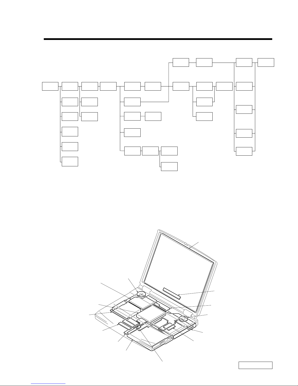
1-1. Flowchart
• P XX means pages that appears in this manual.
• Remember that hard disk drives are easily damaged by vibration. Always handle with care.
1-2. Main Electrical Parts Location Diagram
POWER
OFF
HOOD
KEYBOARD
ASSY
SO-DIMM
BATTERY
PACK
HINGE
COVER
MODEM
CARD
KEYBOARD
UNIT
P 1-2P 1-2
P 1-5P 1-5
P 1-5
P 1-2
P 1-6
P 1-2 P 1-3
P 1-4
3 through 7
P 1-4
P 1-4
P ALM REST
ASSY
P 1-3
DC
FAN
PC CARD
CONNECTOR
FDD
SPEAKER
UNIT
SWX-73
BOARD
P 1-3
DISPLAY
ASSY
P 1-4
FPC
INVERTER
ASSY
BRACKET
LCD LEFT
BRACKET
LCD RIGHT
DISPLAY
HOUSING
ASSY
BEZEL
HOUSING
ASSY
DVD-ROM
COMBINATION
DRIVE
LCD
UNIT
PWS-13
BOARD
P 1-4
P 1-3
HDD
∗P 1-7
(P 1-9)
〈P 1-11〉
[
P 1-13]
∗P 1-7
(P 1-9)
〈P 1-12〉
[
P 1-14]
∗P 1-8
(P 1-10)
〈P 1-12〉
[
P 1-14]
∗P 1-8
(P 1-10)
〈P 1-12〉
[
P 1-14]
∗P 1-8
(P 1-10)
〈P 1-12〉
[
P 1-14]
∗:FX190 Model
( ):FX150/FX170 Model
〈 〉:FX140 Model
[ ]:FX120 Model
〈P 1-12〉
[
P 1-14]
〈
P 1-12〉
[
P 1-14]
∗P 1-8
(P 1-10)
〈P 1-12〉
[
P 1-14]
LCD
HARNESS
P 1-2
PARM REST
PLATE
P 1-2
BRACKET
PAT
P 1-2
TOUCH
PAD
CNX-125
BOARD
P 1-2
MODEM
CARD
LATCH
DETECTOR
I/O
BRACKET
MBX-49
BOARD
P 1-4
LITHIUM
BATTERY
P 1-4
LCD Unit
Inverter Assy
Speaker Unit
DVD-ROM Drive
Combination Drive
(CD-RW/DVD-ROM)
PWS-13 Board
FD Drive
CNX-125 Board
MBX-49 Board
Speaker Unit
DC Fan
HDD
SWX-73 Board
Touch Pad
Modem Card
1-2
Confidential
PCG-FX120/FX140/FX150/FX170/FX190 (UC)
1-3.Removal
1. Hinge Cover
2. Keyboard Unit, Palm Rest Assy, Hood Keyboard Assy, Touch Pad, CNX-125 Board
2Hinge Cover
1Door I/O
3
4
2Hinge Cover
3Hood Keyboard Assy
6Keyboard Unit
0Palm Rest Assy
5
8M2X4
Special Head
(Black)
7Screw (M2),
0 Number P3 Kind (X4) (Black)
PWS-13 Board
CN4004
MBX-49 Board
CN2004
MBX-49 Board
CN1902
1M2X4 Special Head (Black)
4M2X4 Special Head (Black)
qsM2X4 Special Head (x4) (Black)
qhBracket Pat
qjTouch pad
qfPalm Rest
Plate
qkCNX-125
Board
2Pull it up sliding it
to the right.
9Pull it to the front slightly
and raise to remove it.
qdRemove by
pulling slightly
to the front
qgRemove by
pressing to
the rear
qa
1-3
Confidential
PCG-FX120/FX140/FX150/FX170/FX190 (UC)
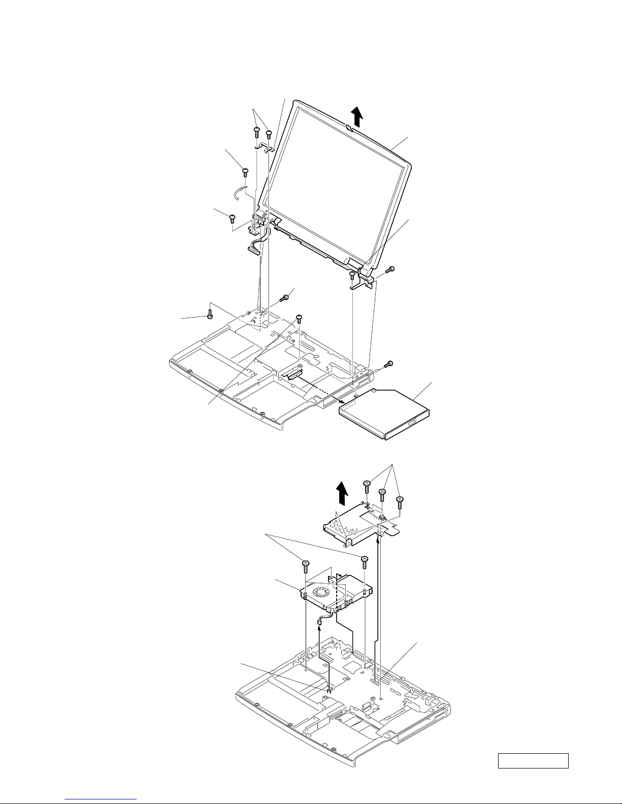
3. Display Assy, DVD-ROM Drive, Combination Drive (CD-R W/DVD-ROM)
4. HDD Assy, DC Fan
Display Assy
3
8M2X6 Special Head (Black)
9
1Screw (M2),
0 Number P3 Kind
(Black)
7M2X6
Special Head (Gold)
2M2X6 Special Head
(Gold)
6M2.6 Cross
(Hole) Bind
(Black)
6M2.6 Cross (Hole) Bind (X2) (Black)
6M2.6 Cross (Hole) Bind (Black)
4+B 2X12 (Black)
4+B M2 (X2) (Gold)
5Plate Ground
DVD-ROM Drive
Combination Drive
(CD-RW/DVD-ROM)
6DC Fan
5
MBX-49 Board
CN102
3HDD Assy
2FPC 50 Pin (for HDD)
1M2X6 Special Head (X6) (Gold)
4Screw (M2) 0 Number
P3 Kind (X4) (Black)
MBX-49 Board
CN2201
1-4
Confidential
PCG-FX120/FX140/FX150/FX170/FX190 (UC)
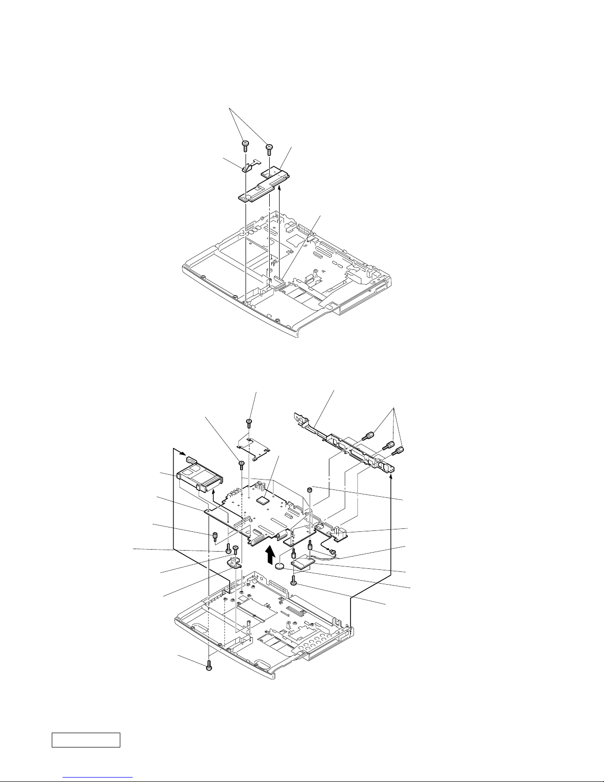
5. Latch Detector, PWS-13 Board
6. PC Card Connector, Modem Card, MBX-49 Board, Lithium Battery
∗1 When removing the CPU, refer to “ 1-4. Replacing the CPU ”.
∗2 Modem card can be removed from the bottom.
Refer to the subsequent paragraph “ 9. Modem card ” for more details.
4PWS-13 Board
3
2Latch Detector
1M2X4 Special Head (X2) (Black)
MBX-49 Board CN2701
qkMBX-49 Board
9PC Card Connector
qdM2 Grip (X2) (Black)
8+B 2X14 (X2)
(Silver)
3Screw (MBX)
(Silver)
qjI/O Bracket
qhScrew (HEX) (X6) (Silevr)
7
qs
5Bracket Bay Connector
4M2X4 Special Head
(X2) (Black)
CN151
Modem Card
*
2
qsNUT M2 TYPE2 (X2)
CPU
*
1
1M2X4 Special Head
(X2) (Black)
2M2X4 Special Head
(X5) (Black)
6Screw (M2) 0 Number
P3 Kind (X2) (Black)
0Lithium Battery
qgSpacer (MBX)
(X2)
1-5
Confidential
PCG-FX120/FX140/FX150/FX170/FX190 (UC)
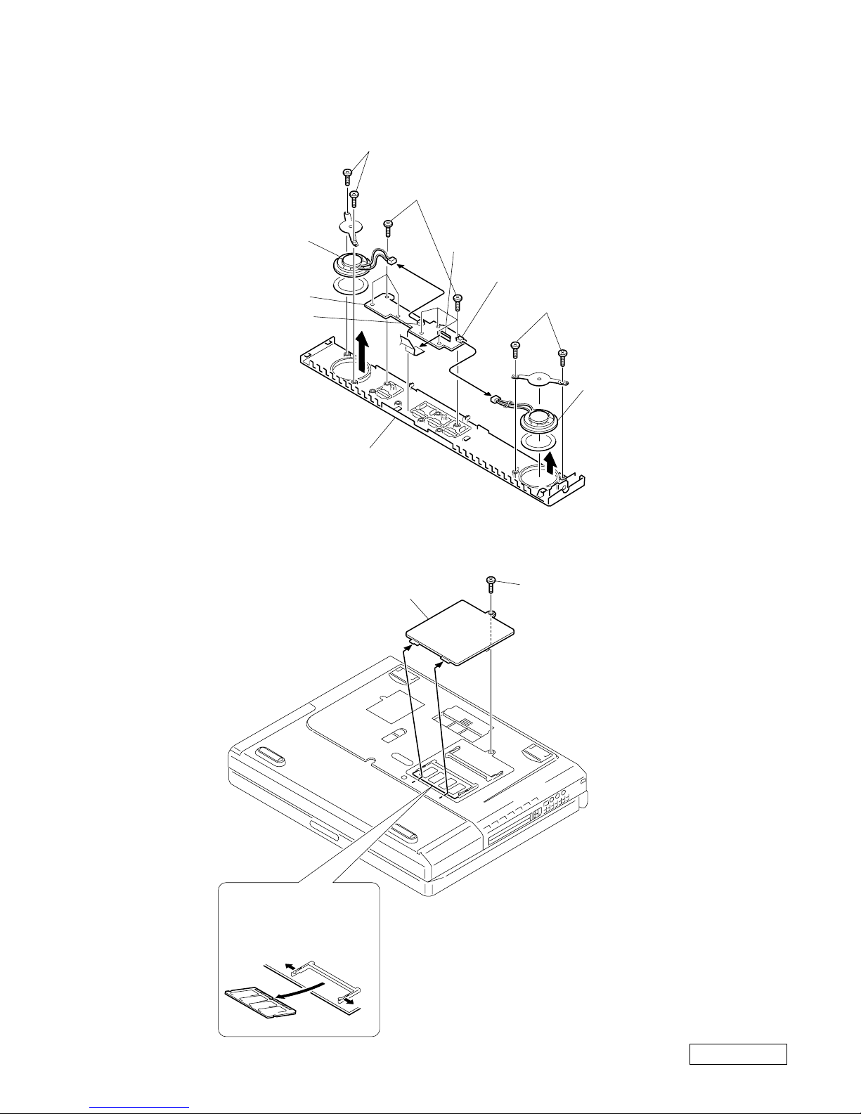
7. Speaker Unit, SWX-73 Board
8. SO-DIMM
4Speaker Unit
6Hood Keyboard
5SWX-73 Board
4Speaker Unit
2M2X4 (X7) (Black)
1
1
1
3M2X4 (X2) (Black)
3M2X4 (X2) (Black)
SWX-73 Board
CN303
SWX-73 Board
CN301
SWX-73 Board
CN302
2DIMM Door
1M2X4 Special Head (Black)
b
a
a
Removal of SO-DIMM
a → b
1-6
Confidential
PCG-FX120/FX140/FX150/FX170/FX190 (UC)
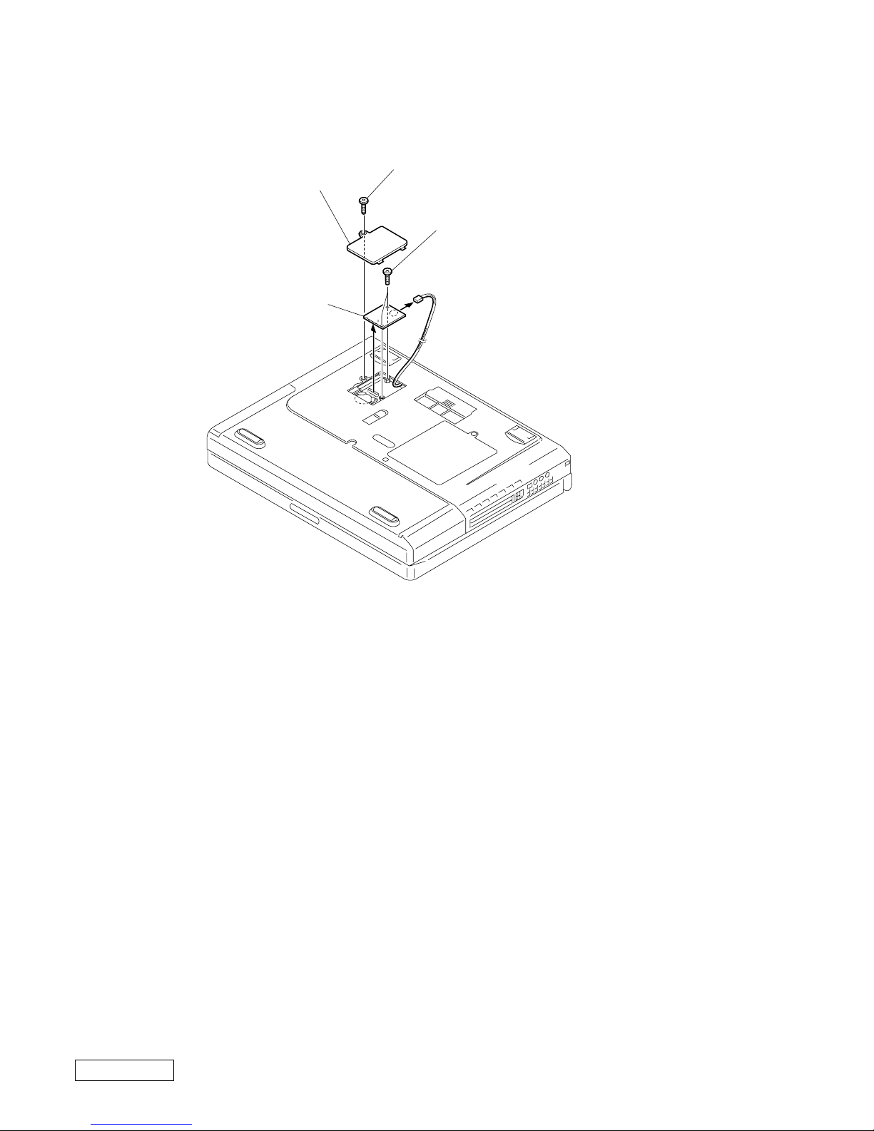
9. Modem Card
2Modem Door
4Modem Card
1M2X4 Special Head (Black)
3M2 Grip (X2) (Black)
5
1-7
Confidential
PCG-FX120/FX140/FX150/FX170/FX190 (UC)
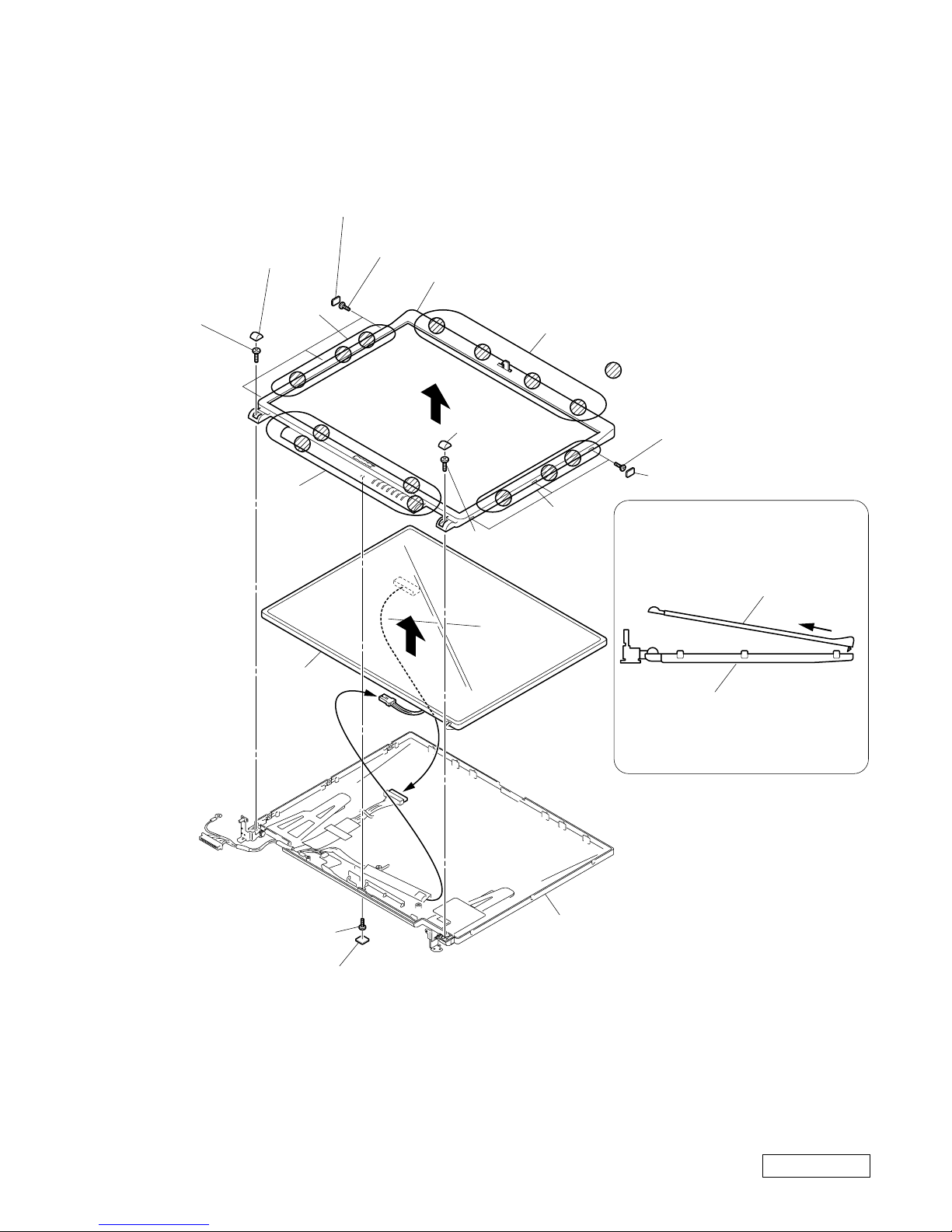
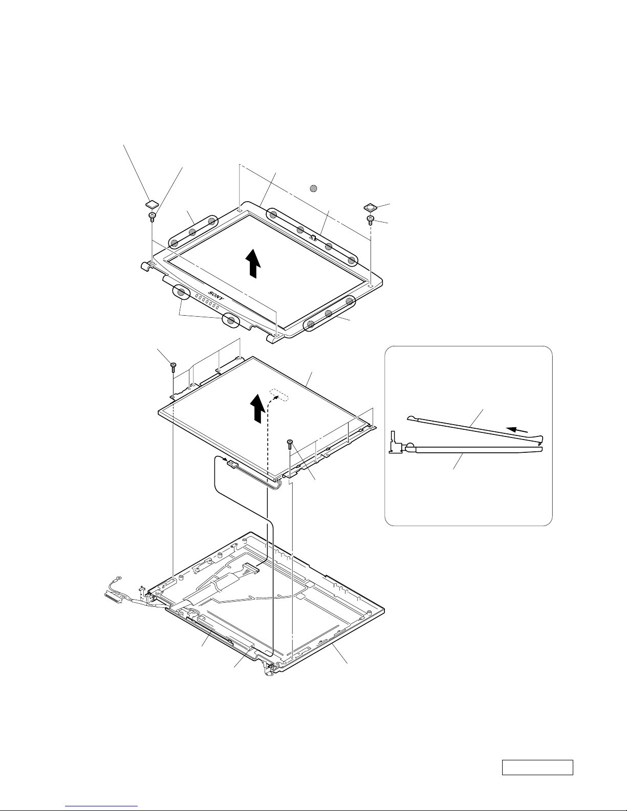
10. LCD Section (FX190 Model) – Made by SA –
1. Bezel Housing Assy, LCD Unit (15 inch)
How to release the claw A.
Pull the Bezel Housing Assy
as shown to release the claw A.
Bezel Housing Assy
Display Housing Assy
A
Order of releasing the claws C → B → A
Order of locking the claws A → B → C
Display Housing Assy
: claw part
1Side (15) Screw Cover (X3) (Gold)
5Lower Screw Cover
3Cover Screw
Shaft
3Cover Screw
Shaft
4+P 2.6X6
Lock Precision
Type3 (Black)
4+P 2.6X6 Lock
Precision Type3
(Black)
6M2X4 Special Head
(Black)
1Side (15) Screw Cover (X3)
2+P M2X3 (X3) (Gold)
2+P M2X3 (X3)
A
B
7
0
8
9
B
C
Bezel Housing Assy
LCD unit
1-8
Confidential
PCG-FX120/FX140/FX150/FX170/FX190 (UC)
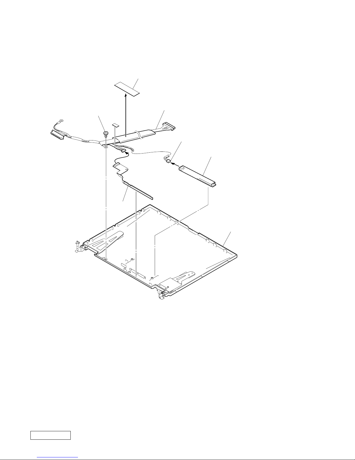
2. Inverter Assy, LCD Harness, FPC, Display Housing Assy
1
3
2Inverter Assy
9Display Housing Assy
Inverter Assy
CN2
4FPC
7M2X4 Special Head
(Black)
8LCD Harness
5
6Shield Tape (SK)

1-9
Confidential
PCG-FX120/FX140/FX150/FX170/FX190 (UC)
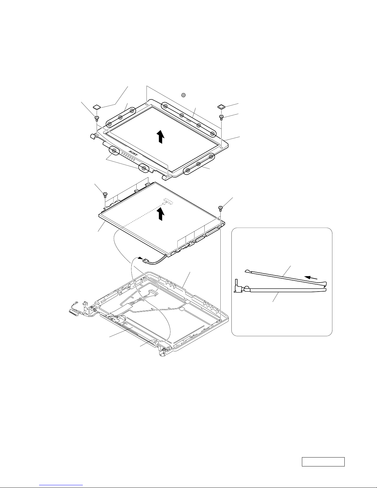
11. LCD Section (FX150/FX170 Model) – Made by SA –
1. Bezel Housing Assy, LCD Unit (15 inch)
How to release the claw A.
Pull the Bezel Housing Assy
as shown to release the claw A.
Bezel Housing Assy
Display Housing Assy
A
Order of releasing the claws C → B → A
Order of locking the claws A → B → C
Display Housing Assy
: claw part
1Side (15) Screw Cover (X3) (Gold)
5Lower Screw Cover
3Cover Screw
Shaft
3Cover Screw
Shaft
4+P 2.6X6
Lock Precision
Type3 (Black)
4+P 2.6X6 Lock
Precision Type3
(Black)
6M2X4 Special Head
(Black)
1Side (15) Screw Cover (X3)
2+P M2X3 (X3) (Gold)
2+P M2X3 (X3)
A
B
7
0
8
9
B
C
Bezel Housing Assy
LCD unit

1-10
Confidential
PCG-FX120/FX140/FX150/FX170/FX190 (UC)
2. Inverter Assy, FPC, Display Housing Assy
1
3
2Inverter Assy
9Display Housing Assy
Inverter Assy
CN2
4FPC
7M2X4 Special Head
(Black)
8LCD Harness
5
6Shield Tape (SK)
1-11
Confidential
PCG-FX120/FX140/FX150/FX170/FX190 (UC)
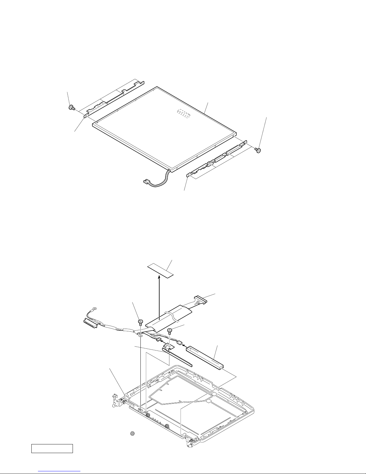
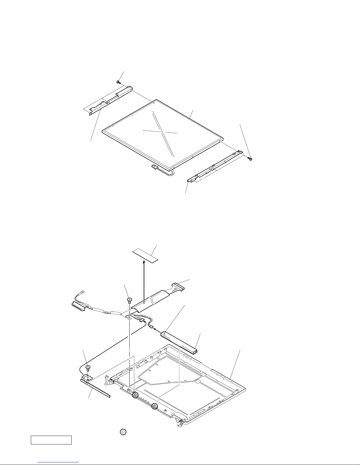
12. LCD Section (FX140 Model) – Made by SA–
1. Bezel Housing Assy
Order of releasing the claws c → b → a
Order of locking the claws a → b → c
How to release the claw a
5
a
Pull the Bezel Housing
Assy as shown to release
the claw a.
: claw part
a
b
c
b
1Cover Screw Lower
1Cover Screw Upper
2M2X4 Special
Head (X2) (Black)
2M2X4 Special Head (X2)
(Black)
4M2X4 Special Head (X5) (Black)
4M2X4 Special
Head (X5) (Black)
6
7
3
Display Housing Assy
Inverter Assy
Inverter Assy
CN2
Bezel Housing Assy
Display Housing Assy
Bezel Housing Assy
LCD Unit
1-12
Confidential
PCG-FX120/FX140/FX150/FX170/FX190 (UC)
2. Bracket LCD Left, Bracket LCD Right, LCD Unit (14 inch)
3. FPC, Inverter Assy, Display Housing Assy, LCD Harness
5LCD Unit
2Bracket LCD Right
4Bracket LCD Left
1+P M2x3 Lock (X4)
(Black)
3+P M2x3 Lock (X4)
(Black)
: claw part
5M2X4 Special Head (Black)
6M2X4 Special Head
(Black)
9Display Housing Assy
4FPC
2Inverter Assy
3
1
7
8Shield Tape (SK)
0LCD Harness
1-13
Confidential
PCG-FX120/FX140/FX150/FX170/FX190 (UC)
13. LCD Section (FX120 Model) – Made by AC–
1. Bezel Housing Assy
Bezel Housing Assy
Display Housing Assy
A
7
4M2X4
Special
Head (X5) (Black)
6
5
LCD Unit
How to release the claw A.
Pull the Bezel Housing Assy
as shown to release the claw A.
: claw part
B
B
3
1Upper Screw Cover (x2)
2M2X4
Special
Head (X2) (Black)
2M2X4
Special
Head (X2)
(Black)
1Lower Screw Cover (x2)
A
C
Bezel Housing Assy
Display Housing Assy
Inverter Assy
CN2
Inverter Assy
4M2X4
Special
Head (X4)
(Black)
Order of releasing the claws C → B → A
Order of locking the claws A → B → C
1-14
Confidential
PCG-FX120/FX140/FX150/FX170/FX190 (UC)
2. Bracket LCD Left, Bracket LCD Right, LCD Unit (13 inch)
3. FPC, Inverter Assy, Display Housing Assy, LCD Harness,
5LCD Unit
1+PS M2x3 (X3) (Black)
1+PS M2X3 (X3) (Black)
4Bracket LCD Left
2Bracket LCD Right
: claw part
9M2X4
Special Head (Black)
4M2X4
Special Head
(Black)
Inverter Assy
CN1
2Inverter Assy
qaDisplay Housing Assy
7
8Shield Tape (SK)
5FPC
3
1
0LCD Harness
1-15
Confidential
PCG-FX120/FX140/FX150/FX170/FX190 (UC)
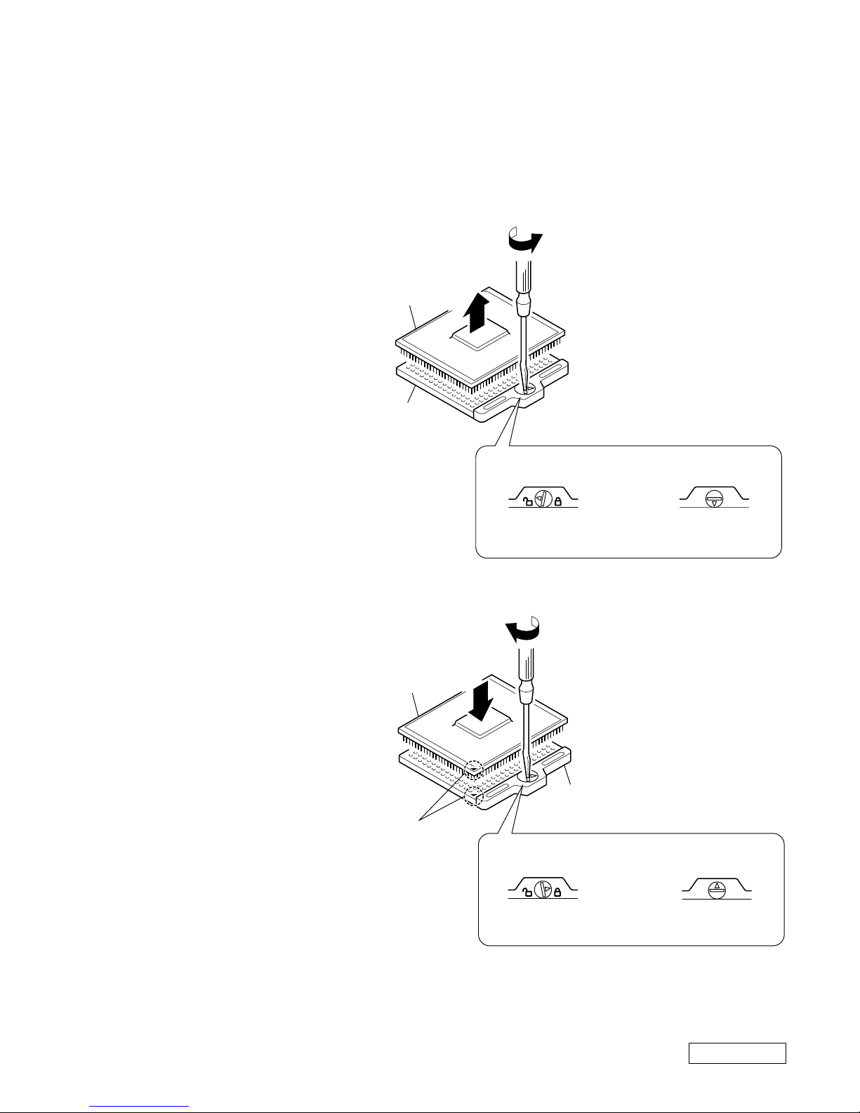
1-4.Replacing the CPU
NOTE:
This computer uses either one of the two types of CPU socket.
The CPU locking position and the lock-release position are different depending on the types of the CPU socket.
1. Removing the CPU
2. Installing the CPU
1 Align the triangle reference mark of
the CPU with that of the CPU socket
and insert all the pins of the CPU to
the corresponding holes of the CPU
socket.
2 Insert a flat-blade screwdri ver into the
notch as shown in the illustration and
rotate it so that the protrusion comes
to the lock position.
1 Insert a flat-blade screwdriv er into the
notch as shown in the illustration and
rotate it so that the protrusion comes
to the lock release position.
2 Pull the CPU gently upward to lift it
out of the CPU socket.
NOTE:
Rotate a flat-blade screwdriver to the lock position securely. If not, the operation of the CPU may become unstable.
1
2
FX120/FX140 Model FX150/FX170/
FX190 Model
2
1
FX120/FX140 Model FX150/FX170/
FX190 Model
CPU socket
CPU
Lock release position
(made by HIROSE)
Lock release position
CPU socket
CPU
Lock position
(made by HIROSE)
Lock position
Reference
marks
1-16
Confidential
PCG-FX120/FX140/FX150/FX170/FX190 (UC)
1-5. DIP Switch Setting of the MBX-49 Board
The DIP switch on the MBX-49 board (main board) is set to match with the LCD that is used in this computer,
because several types of LCD are used as shown in the following table and the DIP switch setting differs depending
on the LCD type.
NOTE:
The main LCD is used in most cases but there are also cases that the sub LCD is used.
MODEL
FX190
FX150/FX170
Name of LCD
SA
HI
SA
HI
Part No.
1-476-576-11
A-8048-250-A
1-418-574-41
A-8066-124-A
DIP switch setting
The upper position where ON indication is
shown is the ON position .
The lower position is the OFF position.
The upper position where ON indication is
shown is the ON position .
The lower position is the OFF position.
The upper position where ON indication is
shown is the ON position .
The lower position is the OFF position.
The upper position where ON indication is
shown is the ON position .
The lower position is the OFF position.
12345678
10011111
0 : ON 1: OFF
No.
ON/OFF
12345678
01010111
0 : ON 1: OFF
No.
ON/OFF
12345678
01111111
0 : ON 1: OFF
No.
ON/OFF
12345678
00110111
0 : ON 1: OFF
No.
ON/OFF
Note
Main
Sub
Main
Sub
1234567
8
O
N
1234567
8
O
N
1234567
8
O
N
1234567
8
O
N
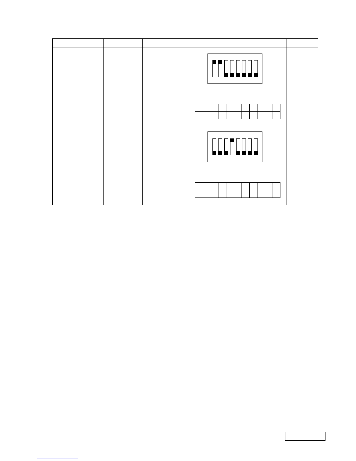
1-17
Confidential
PCG-FX120/FX140/FX150/FX170/FX190 (UC)
(END)
MODEL
FX140
FX120
Name of LCD
SA
AC
Part No.
1-418-716-21
1-418-882-11
DIP switch setting
The upper position where ON indication is
shown is the ON position .
The lower position is the OFF position.
The upper position where ON indication is
shown is the ON position .
The lower position is the OFF position.
Note
Main
Main
12345678
00111111
0 : ON 1: OFF
No.
ON/OFF
12345678
11101111
0 : ON 1: OFF
No.
ON/OFF
1234567
8
O
N
1234567
8
O
N
2-1 PCG-FX120/FX140/FX150/FX170/FX190 (UC)
Confidential
CHAPTER 2.
SELF DIAGNOSTICS
2-1. Required Tools and Peripheral Devices
Test Items
Serial Port (COM) test
Parallel Port (printer) test
Audio related tests
Modem test
PC Card test
IEEE1394 test
Test of Serial/Parallel
DVD-ROM Drive and Combination
Drive (CD-RW/DVD-ROM) tests
FDD test
(Diagnostics starting software)
(Diagnostics software)
Battery related tests
(Power supply for diagnostics)
HDD related tests
Tools and Peripheral Devices
1 Serial Loopback Tool
Specified Loopback Tool (Refer to next page.)
2 Parallel Loopback Tool
Specified Loopback Tool (Refer to next page)
3 Stereo microphone
4 Headphone
5 56K Modem and Line Simulator
6 PC Card Tester
PCCtest 450 Made by Sycard Corp.
7 VAIO for IEEE1394 Test
8 Port Replicator PCGA-PRFX1 for Serial/Parallel tests
9 DVD-ROM and Combination Drive
(CD-RW/DVD-ROM) supplied
10 External FDD
11 Diagnostics FD Media
12 Diagnostics CD-ROM Media
13 Battery supplied
14 AC Adaptor supplied
15 HDD
2-2PCG-FX120/FX140/FX150/FX170/FX190 (UC)
Confidential
• The serial loopback tool and the parallel loopback tool are necessary for diagnostics of the serial communication line and
the parallel communication line. Fabricate the serial loopback tool and the parallel loopback tool locally referring to the
connection diagrams shown below.
[Reference] On Serial/Parallel Loopback Tool
Serial Loopback Tool : For diagnostics of serial port
Parallel Loopback Tool : For diagnostics of parallel port
NOTE: The black round mark "z" indicates soldering.
NOTE: The black round mark "z" indicates soldering.
1
2
3
4
5
6
7
8
9
DB9S
DCD
RX
TX
DTR
GND
DSR
RTS
CTS
RI
• Connector Types DB9S (Female)
• Interface Standard RS-232C
• Loopback Data & Handshake
SERIAL LOOPBACK CONNECTOR CONNECTION DIAGRAM
• Connector Types DB25P(Male)
• Interface Standard Centronics
• Loopback Status to Commands
PARALLEL LOOPBACK CONNECTOR CONNECTION DIAGRAM
1
2
3
4
5
6
7
8
9
10
11
12
13
14
15
16
17
18
19
20
21
22
23
24
25
D0
D1
D2
D3
D4
D5
D6
D7
-ACK
BUSY
PE
SLCT
-STROBE
-AUTO FD
-ERROR
-INT
-SLCT IN
GND
GND
GND
GND
GND
GND
GND
GND
DB25P
2-3 PCG-FX120/FX140/FX150/FX170/FX190 (UC)
Confidential
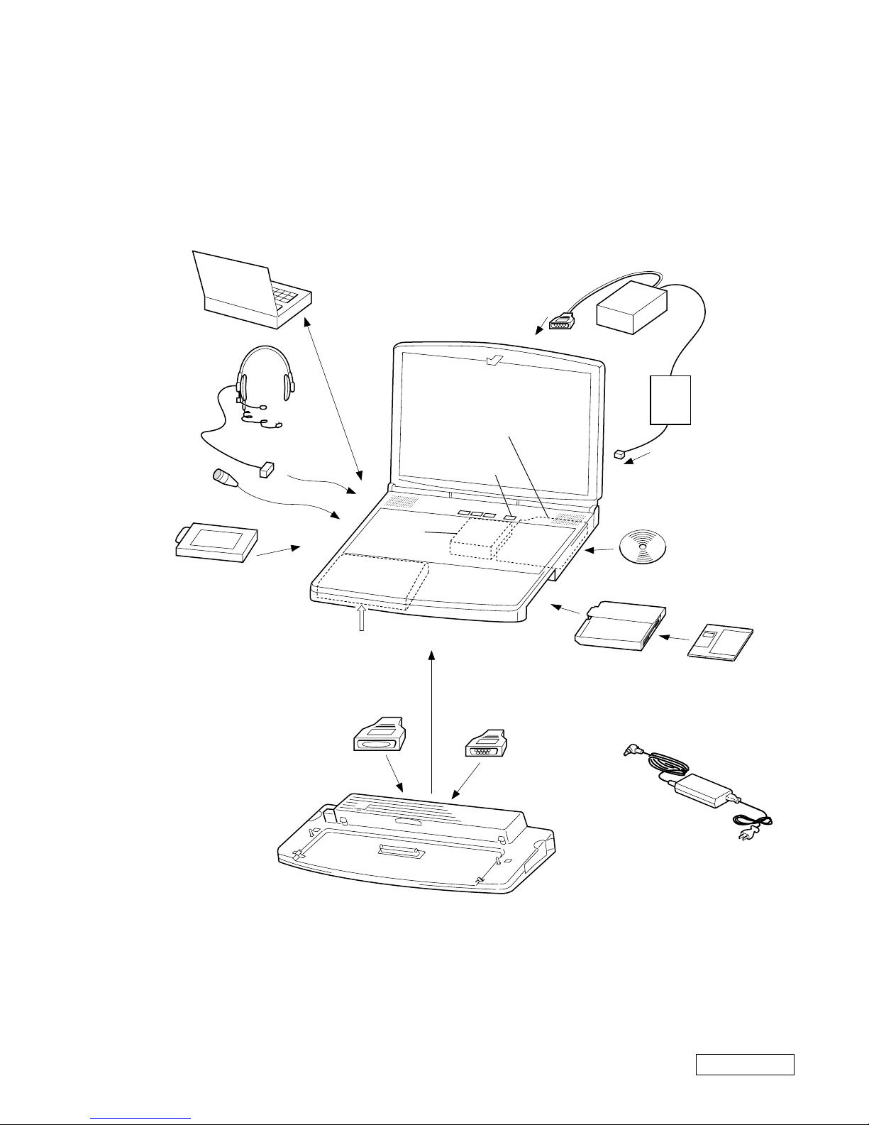
2-2. Tools and Peripheral Device Connection
System Connection Diagram
2Parallel
loopback tool
Modem
qdBattery
1Serial
loopback tool
Port Replicator
Serial I/F
9Combination Drive
(CD-RW/DVD-ROM)
DVD-ROM
Power SW
5Transmission
line simulator
6PC card tester
qsDiagnostics
CD-ROM media
qfAC adaptor
8Port Replicator PCGA-PRFX1
7VAIO for IEEE1394 test
jack
Phone
Serial
output
Parallel
output
0FDD
qaDiagnostics
FD media
qgHDD
3Stereo microphone
MIC IN
4Headphones
Headphones
connector

2-4PCG-FX120/FX140/FX150/FX170/FX190 (UC)
Confidential
2-3. Starting up the Service Diagnostics
1. The service diagnostics floppy disk and CD disc are prepared for the respective models separately. Insert the service
diagnostics floppy disk and CD disc of the desired model, then turn on the main power of the personal computer.
Reads automatically the model information stored in the CD-ROM and displays the test menu. If the CD does not
supported the model, an error message is displayed.
2. The driver software is installed from the CD disc, the necessary ROM information is automatically read and the initial
settings are made, then the following self-diagnostics menu appears.
*************** Main Menu ****************
1:Check ROM Information... d:Parallel Loopback test...
2:Battery test... e:PC Card Slot test...
3:CD/DVD Drive test... f:Video test...
4:FDD test... g:PPK test...
5:HDD test... h:GUID (IEEE1394) test...
6:Keyboard test... i:IEEE1394 Interface test...
7:LED test... j:IrDA test...
8:Main memory test... k:Jog dial test...
9:Main system test... l:Short aging test...
a:FAN test... m:Long aging test...
b:Touch pad test... n:Aging test including the HDD test...
c:Serial Loopback test... o:Exit from Diagnostics MENU
3. When the service diagnostics ends with success, the message “Pass” appears. When it ends with failure detecting an error,
the message “Fail” appears. Press the “Esc” key to abort the self diagnostics.
2-4. Outline of Service Diagnostics Functions
• Check ROM Information...
Displays the model information, serial number, BIOS and other information saved in the BIOS ROM.
Does not test whether or not the personal computer is normal.
• Battery test...
T ests the battery as to whether the battery is attached or removed, the main po wer is supplied from an A C po wer adapter or
not, and the battery is charged or discharged. The test procedure appears on display. Perform the battery test following the
messages on display.
Remove and attach the battery → Check (Removal and attachment of battery)
Disconnect and connect the AC power → Check (Disconnection and connection of AC power)
Remove and attach the battery → Check (Discharge and charge of battery)
• CD/DVD Drive test...
Tests the CD, CD-R, Combination drive ( CD-RW/ DVD-ROM) , CD-RW and DVD drives.
• FDD test...
Tests the floppy disk drive.

2-5 PCG-FX120/FX140/FX150/FX170/FX190 (UC)
Confidential
• HDD test...
T ests whether the HDD returns a response when communication is established with the hard disk drive. The HDD can be
tested without damaging the HDD data (without formatting the HDD) in this test since the HDD data is tentatively stored
in memory during the test.
If the main power is turned off by mistak e while the test is under way, the HDD data can be damaged. Tests the following
test automatically.
1. HDD interface test (Tests whether or not the HDD is recognized)
2. HDD seek test
3. HDD read test
4. HDD write test
5. HDD random read test and random write test (It takes about 2 hours for the 18 GB HDD. This time is a guideline and
changes depending on the model.)
6. Returns to the main menu.
• Keyboard test...
Tests the keyboard. When the “Auto select” menu is selected, the keyboard type in use is recognized from the model
information that is written in ROM when shipped from the factory and the test is executed accordingly. When a specific
keyboard type is selected such as US, UK, or JP, then the keyboard of the selected type is tested. If the model of your
computer is JP and the keyboard type is replaced by either the US type or UK type keyboard, select the k eyboard type after
it is replaced.
NOTE: The “Fn” key can be checked by pressing the “Fn” and “→” keys at the same time. Other keys can be
checked by pressing the respective keys.
• LED test...
T ests the LED. This test tur ns on one LED after another. The person conducting the test must visually check whether each
LED is normal or not.
• Main Memory test...
T ests the main memory. The Main Memory test contains the follo wing three test menus. Select the desired menu that suits
your need. The test is exited automatically when the respective test items end normally.
⋅ Fast: Tests once. (Taking one and half minutes to two minutes)
⋅ Medium: Test ten times.
⋅ Heavy: Test twenty times.
Press the “Esc” key to abort the test.
• Main System test...
Tests the fundamental functions of the CPU, etc. The test is exited automatically when all test items end normally.
• FAN test...
Tests the fan. Tests whether the fan rotates and stops. Listen to the rotating sound or feel the wind of the fan to judge
whether the fan rotates and stops. The test procedure appears on display. Perform the F AN test f ollo wing the messages on
display. Press “Y” to resume rotation when the f an comes to stop. Press “Y” when the fan starts rotating indicating that the
test ends in success.

2-6PCG-FX120/FX140/FX150/FX170/FX190 (UC)
Confidential
• Touch pad test...
Tests the touch pad. Tests whether the cursor moves, and whether right-clicking and left-clicking function properly.
The dialog box appears three times. Move the cursor to the box that appears. The tests are performed in the follo wing order .
(1) Touch pad
(2) Left-click button
(3) Right-click button (Two times)
• Serial loopback test...
Performs the loopback test of the serial port. Connect the port replicator and the loopback tool to the serial port.
• Parallel loopback test...
Performs the loopback test of the parallel port. Connect the port replicator and loopback tool to the parallel port.
• PC card Slot test...
Tests the PC card slot. Implements the 16-bit/card-bus test for the two slots of the main unit.
• Video test...
The video test cannot be performed on the MS-DOS prompt.
Go to Video inspection of Chapter “2-5. Inspecting Windows” for the video test.
• PPK test...
T ests the PPK. If the test is not completed within the specified time, an error is triggered due to the time-out set for this test.
When two or more PPKs are set, follow the instructions that appear on the screen.
• GUID test...
This test is not required normally. Displays the GUID (i.Link ID value), and judges whether the value on the display is
appropriate.
• IEEE 1394 Interface test...
Performs the 1394 communication test. Another personal computer to communicate with is necessary for this test. The
models released from the year 2000 have already been confirmed that they do not cause any problems regarding the
IEEE1394 interface. Even models released before 2000 will cause no problem if the same type of IEEE1394 interface IC
chip (the IC chip used in the iLink block connected to the PCI bus) is used in both personal computers that are connected.
In other combinations, the IEEE1394 interface test is not confirmed. (Use of the models released from the year 2000 is
recommended.)
1. Connect the iLink cable.
2. Start up the personal computer at the other end of the IEEE1394 interface test connection using the tool floppy disk
that must be created beforehand by copying programs from the service diagnostics CD disc. (Prepare a floppy disk
that is formatted to contain the DOS system. Create a tool floppy disk by copying the entire TOOL folder of the CD
disc to a floppy disk.)
3. Select the 1394 test from the menu at the connected computer to enter the reception state.
4. After the connected personal computer has entered the reception state, select the 1394 test at the personal computer to
be tested. The IEEE1394 interface test then starts. Send and receive of the random data are repeated five times
(i.e., this test is repeated five times.)

2-7 PCG-FX120/FX140/FX150/FX170/FX190 (UC)
Confidential
• IrDA test...
The computer cannot perform this test.
• Jog dial test...
The computer cannot perform this test.
• Short aging test.../Long aging test...
Performs the aging test. The short aging test ends when all test items have been performed once. The long aging test checks
the machine for about 10 hours by repeating the test items.
• Aging test including the HDD...
NOTE:Note that this test destroys the entire contents of the user’s hard disk drive.
Perform this test only when destructive testing of HDD is desired.
The aging test is performed first, then read and write tests of the hard disk are implemented following the aging test.
There are two tests; SHORT and LONG. However, the contents of the SHORT aging test are the same as those of the
LONG aging test. The test starts immediately when the menu item is selected.
• Exit from Diagnostics MENU...
Quits the service diagnostics program and the DOS prompt appears. If you exit the service diagnostics program by
mistake, start up the program again.
2-5. Inspecting Windows
The Windows inspection contains the following three types of inspection.
Audio
Modem
Video
Before starting inspections, create a floppy disk from the service diag CD to be serviced.
The files to be used for inspection are stored in the following sub directory inside the CD. Cop y all the files in the folder t o the
floppy disk.
Audio \windiag\wave
Modem \windiag\modem
Video \windiag\video
• Audio
A microphone and headphones are required for this inspection.
Double-click “t_auw01” icon (MS-DOS icon) in the floppy disk that is created in adv ance. The display of the DOS prompt
opens and the inspection starts. Once inspection starts, follow the instructions on the display to inspect the audio.
• Modem
A modem and a line simulator are required for this inspection.
Double-click “modem” icon (MS-DOS icon) in the floppy disk that is created in advance.
The display of the DOS prompt opens and the inspection starts.
 Loading...