

Page 1
Page 2

Information in this document is subject to change without notice.
Sony and VAIO are trademarks of Sony. Microsoft, MS-DOS,
Windows, the Windows 95, Windows 98, Windows 2000 and
Windows ME logo are trademarks of Microsoft Corporation.
All other trademarks are trademarks or registered trademarks of
their respective owners. Other trademar ks and trade names may be
used in this document to refer to the entitles claiming the marks and
names or their produces. Sony Corporation disclaims any proprietary
interest in trademarks and trade names other than its own.
Caution Markings for Lithium/Ion Battery - The following or similar
texts shall be provided on battery pack of equipment or in both the
operating and the service instructions.
CAUTION: Danger of explosion if battery is incorrectly replaced.
Replace only with the same or equivalent type recommended by
the manufacturer. Discard used batteries according to the
manufacturer’s instructions.
CAUTION: The battery pack used in this de vice may present a fire
or chemical burn hazard if mistreated. Do not disassemble, heat
above 100°C (212°F) or incinerate.
Dispose of used battery promptly.
Keep away from children.
CAUTION: Changing the back up battery.
• Overcharging, short circuiting, reverse charging, multilation
or incineration of the cells must bi avoided to prevent one or
more of the following occurrences; release of toxic materials,
release of hydrogen and/or oxygen gas, rise in surface
temperature.
• If a cell has leaked or vented, it should be replaced
immediately while avoiding to touch it without any protection.
Service and Inspection Precautions
1. Obey precautionary markings and instructions
Labels and stamps on the cabinet, chassis, and components identify areas
requiring special precautions. Be sure to observe these precautions, as
well as all precautions listed in the operating manual and other associated
documents.
2. Use designated parts only
The set’s components possess important safety characteristics, such as
noncombustibility and the ability to tolerate large voltages. Be sure that
replacement parts possess the same safety characteristics as the originals.
Also remember that the 0 mark, which appears in circuit diagrams and
parts lists, denotes components that have particularly important safety
functions; be extra sure to use only the designated components.
3. Always follow the original design when
mounting parts and routing wires
The original layout includes various safety features, such as inclusion of
insulating materials (tubes and tape) and the mounting of parts above the
printer board. In addition, internal wiring has been routed and clamped so
as to keep it away from hot or high-voltage parts. When mounting parts or
routing wires, therefore, be sure to duplicate the original layout.
4. Inspect after completing service
After servicing, inspect to make sure that all screws, components, and wiring
have been returned to their original condition. Also check the area around
the repair location to ensure that repair work has caused no damage, and
confirm safety.
5. When replacing chip components...
Never reuse components. Also remember that the negati ve side of tantalum
capacitors is easily damaged by heat.
6. When handling flexible print boards...
•The temperature of the soldering-iron tip should be about 270C.
•Do not apply the tip more than three times to the same pattern.
•Handle patterns with care; never apply force.
Caution: Remember that hard disk drives are easily damaged by
vibration. Always handle with care.
Confidential
– 2 –PCG-C1VN (UC)
Page 3

TABLE OF CONTENTS
Section Title Page
CHAPTER 1. REMOVAL
1-1. Flowchart ......................................................................... 1-1
1-2. Main Electrical Parts Location Diagram ......................... 1-1
1-3. Removal ...........................................................................1-2
1. Key Board Unit ................................................................ 1-2
2. Cursor Sensor Module ..................................................... 1-2
3. Parm Rest Sub Assy......................................................... 1-3
4. SWX-62 Board ................................................................ 1-3
5. SWX-63 Board ................................................................ 1-4
6. Speaker (30X15 With Harness) ....................................... 1-4
7. IFX-128 Board ................................................................. 1-5
8. Nickel Hydrogen Battery ................................................. 1-5
9. Assy HDD 12.0 GB ......................................................... 1-6
10. MBX-45 Board ................................................................ 1-6
11. Fan With Heatsink ........................................................... 1-7
12. PC Card Connector (Ejector) ........................................... 1-7
13. LCD Housing Assy .......................................................... 1-8
14. CNX-108 Board ............................................................... 1-8
15. Bezel Assy .......................................................................1-9
16. LCD 1210 Assy................................................................1-9
17. CCD SD22 Assy, Inverter Unit ...................................... 1-10
(to 1-10)
CHAPTER 2. SELF DIAGNOSTICS
2-1. Note.................................................................................. 2-1
2-2. Necessary Equipment ...................................................... 2-1
2-3. Starting the Diagnostics ...................................................2-1
2-4. Diagnosis with Diagnostic Program ................................ 2-1
2-5. Test Items......................................................................... 2-2
2-6. Windows Test................................................................... 2-5
2-7. Other Test not Supported ................................................. 2-5
(to 2-5)
CHAPTER 3. BLOCK DIAGRAM ............................... 3-1
(to 3-2)
CHAPTER 4. FRAME HARNESS DIAGRAM ........ 4-1
(to 4-2)
CHAPTER 5. EXPLODED VIEWS AND
PARTS LIST
5-1. Main Section ....................................................................5-1
5-2. LCD Section .................................................................... 5-3
5-3. Accessories ...................................................................... 5-5
(to 5-5)
• Abbreviations
UC : US model / Canadian model
– 3 –
Confidential
PCG-C1VN (UC)
Page 4
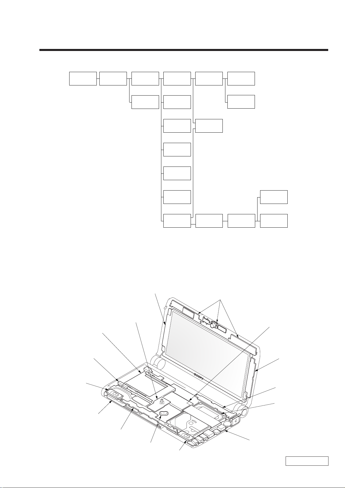
1-1. Flowchart
CHAPTER 1.
REMOVAL
POWER
OFF
KEY BOARD
UNIT
P 1-2
PARM REST
SUB ASSY
P 1-3
CURSOR
SENSOR
MODULE
P 1-2
ASSY HDD
12.0 GB
P 1-6
SWX-62
BOARD
P 1-3
SWX-63
BOARD
P 1-4
SPEAKER
(30X15 WITH
HARNESS)
P 1-4
IFX-128
BOARD
P 1-5
NICKEL
HYDROGEN
BATTERY
P 1-5
LCD
HOUSING
ASSY
P 1-8 P 1-9
MBX-45
BOARD
P 1-6
CNX-108
BOARD
P 1-8
BEZEL
ASSY
FAN WITH
HEATSINK
P 1-7
PC CARD
CONNECTOR
(EJECTOR)
P 1-7
LCD 1210
ASSY
P 1-9
• P XX means pages that appears in this manual.
• Remember that hard disk drives are easily damaged by vibration. Always handle with care.
CCD SD22
ASSY
P 1-10
INVERTER
UNIT
P 1-10
1-2. Main Electrical Parts Location Diagram
LCD 1210 Assy
CCD SD22 Assy
Cursor Sensor
Module
MBX-45 Board
PC Card Connector
(Ejector)
Speaker
(30X15 With Harness)
Fan With Heatsink
SWX-63 Board
Nickel Hydrogen
Battery
Speaker
(30X15 With Harness)
IFX-128 Board
Inverter Unit
SWX-62 Board
Assy HDD 12.0 GB
CNX-108 Board
Confidential
1-1 PCG-C1VN (UC)
Page 5
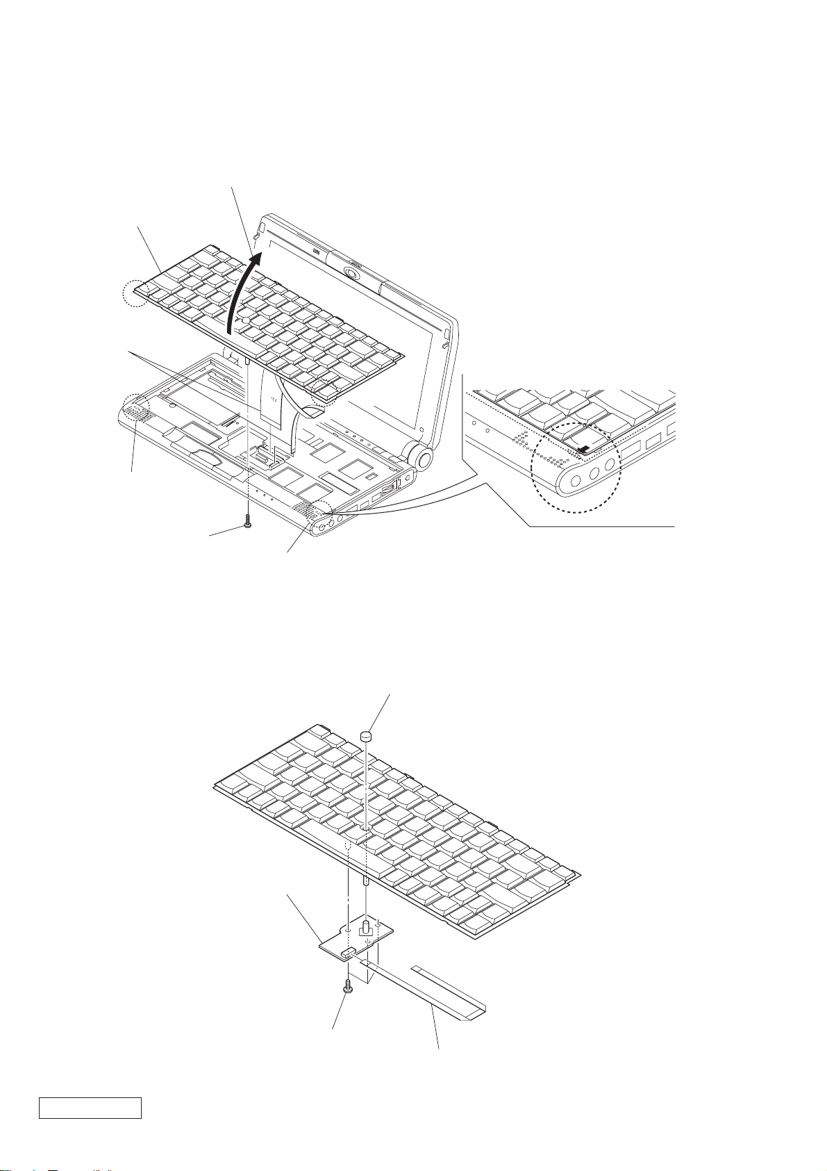
1-3. Removal
1. Key Board Unit
Key Board Unit
4 Harness
2 Claw
3 Open in the direction of arrow.
1 M2X8
2. Cursor Sensor Module
Cursor Sensor Module
2 Claw
1 Cap Sensor
Confidential
2 M2X3 Grip
3 FFC (MBX-TP1)
1-2PCG-C1VN (UC)
Page 6
3. Parm Rest Sub Assy
1 Heatsink (Card Slot)
4 M2X6
8 FFC
(MBX-SWX63)
5 M2X6
9 Claw
7 FFC
(MBX45-SWX62)
5 M2X6
Parm Rest Sub Assy
2 Undo three claws and
remove the main cover (L).
3 Undo three claws and
remove the main cover (R).
4. SWX-62 Board
6 M2X8
6 M2X8
SWX-62 Board
2 FFC
(MBX45-SWX62)
1-3 PCG-C1VN (UC)
1 M2X4
Confidential
Page 7
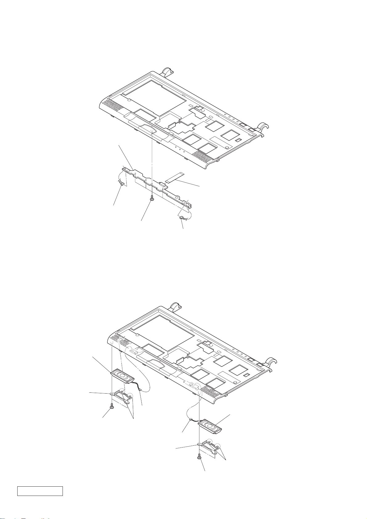
5. SWX-63 Board
SWX-63 Board
3 FFC (MBX-SWX2)
2 Harness
6. Speaker (30X15 With Harness)
Speaker
(30X15 With Harness)
3 Speaker
Retainer
1 M2X4
1 M2X4
4 Harness
2 Claw
2 Harness
Speaker
(30X15 With Harness)
Confidential
4 Harness
3 Speaker
Retainer
2 Claw
1 M2X4
1-4PCG-C1VN (UC)
Page 8
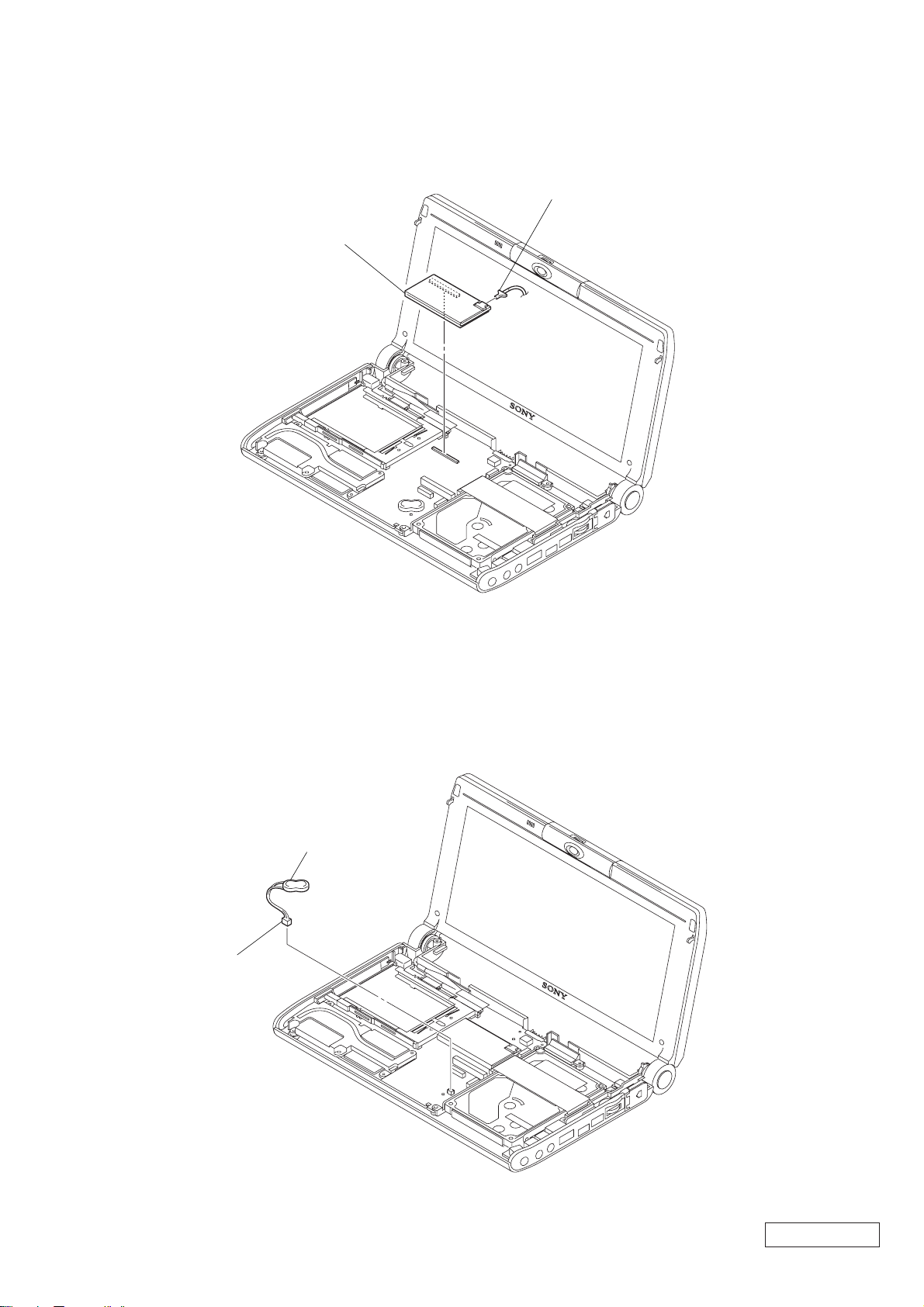
7. IFX-128 Board
1 Harness
IFX-128 Board
8. Nickel Hydrogen Battery
2 Nickel Hydrogen Battery
1 Harness
Confidential
1-5 PCG-C1VN (UC)
Page 9

9. Assy HDD 12.0 GB
1 FFC (MBX-45-CNX108)
2 M2X5
2 M2X5
Assy HDD 12.0 GB
10. MBX-45 Board
6 Escutcheon (L)
Sub Assy
MBX-45 Board
3 Print PWB Simple
Substance
4 M2X5
5 Hole Blind
1 LCD Harness
3 Harness With
Connector (DC)
2 Harness
Confidential
1-6PCG-C1VN (UC)
Page 10

11. Fan With Heatsink
Thermal Sheet (T)
Fan With Heatsink
The fan with heatsink must be installed
*
with the thermal sheet (T) in soft state to
protect the CPU from the stress.
For this purpose, with the thermal sheet
(T) pasted, warm the fan with heatsink to
about 70 °C, and when the thermal sheet
(T) has become soft, install the fan with
heatsink on the main board.
12. PC Card Connector (Ejector)
1 Harness
2 M2X4
1 +PS 2X8
PC Card Connector (Ejector)
Confidential
1-7 PCG-C1VN (UC)
Page 11

13. LCD Housing Assy
LCD Housing Assy
1 LCD Harness
14. CNX-108 Board
2 M2X5
3 M2X3 Grip
1 Harness With
Connector (DC)
2 M2X6
Confidential
CNX-108 Board
3 Modular Harness
4 Escutcheon R
1-8PCG-C1VN (UC)
Page 12

15. Bezel Assy
6 Blind Rubber
(Left)
1 Undo three claws
and remove the hinge
cover assy.
8 Undo ten claws and
remove the bezel assy.
7 M2X5
3 M2X6
16. LCD 1210 Assy
2 Blind Rubber
(Lower)
LCD 1210 Assy
2 Blind Rubber
(Lower)
5 M2X5
4 Blind Rubber (Right)
1 Undo three claws and
remove the hinge cover assy.
3 M2X6
2 LCD Harness
1 M2X4
3 Harness
Confidential
1-9 PCG-C1VN (UC)
Page 13

17. CCD SD22 Assy, Inverter Unit
6 Microphone Assy,
3 LCD Harness
5 Spring Bolt
(M2.6)
CCD SD22 Assy
4 M2X4
1 Flexible Print PWB
2 Inverter Unit
0 Spring Bolt
9 Microphone
Cover Assy
7 Blind Plate
qa Microphone
Holder
(M2.6)
8 M2X3
(Microphone)
qd Tapping Screw
qs Ring (F)
When mounting the ring (F),
*
Align markings of camera
(side of gear) and groove of
ring (F).
If disintegrated, do not turn
*
ring (F).
Focus adjustment is off.
(1.7X3)
qf Bearing (C)
CCD SD22 Assy
Do not dismantle
*
the CCD SD22 Assy.
For example, removing
the connector.
Groove
Marking
Confidential
1-10PCG-C1VN (UC)
(END)
Page 14

CHAPTER 2.
SELF DIAGNOSTICS
2-1. Note
This diagnostics document covers the checking items and the selftest that can be conducted on the set and the FDD & CDROM drive.
2-2. Necessary Equipment
• PCG-C1VN set
• Floppy disk drive
• CD-ROM drive
• Battery
• AC adapter
• CD-ROM for Diagnostics
• FD for Diagnostics (DOS system should be loaded)
• Other jigs and tools necessary for the test
(All may not be required, but if not missing, some items cannot be tested.)
• PCG-C1VN series (IEEE 1394 Interface, etc.)
2-3. Starting the Diagnostics
Connect the FDD, CD-ROM drive, battery, and AC adapter to the PCG-C1VN set (simply called the set).
Insert the FD for Diagnostics in the FDD, and CD-ROM for Diagnostics in the CD-ROM drive.
2-4. Diagnosis with Diagnostic Program
With the FD for Diagnostics inserted in the FDD and the CD-R OM for Diagnostics in the CD-ROM dri ve, turning on the po wer
switch on the set allows the diagnostic program to start from the CD, then the following screen to appear.
• Diagnostics Menu
************ Main Menu ************
1:Check ROM Information... c:GUID (IEEE1394) test...
2:Battery test... d:IEEE1394 Interface test...
3:HDD test... e:IrDA test...
4:Keyboard test... f:Jog dial test...
5:LED test... g:Camera test...
6:Main memory test... h:Shutter Button test...
7:Main system test... i:Short aging test...
8:Fan test... j:Long aging test...
9:Touch pad test... k:Aging test including the HDD test...
a:Video test... l:Exit from Diagnostics MENU
b:PPK test...
Confidential
2-1 PCG-C1VN (UC)
Page 15

Select one menu item, and that item will be tested automatically.
As some items will prompt you to press a key or hear a sound, perform operation following the instructions.
• For the contents of menu items, refer to 2-5. Test Items. (Contents may change a little.)
If the test successfully completed,
******
PASS
******
or, if the test failed
******
FAIL
******
is displayed.
To abort the test, press the [Esc] key.
2-5. T est Items
• Check ROM Information...
Model information, serial number, BIOS, etc. written to the BIOS ROM are displayed.
Whether the information is correct is not tested.
• Battery test...
The battery test is conducted. Battery mounting/demounting, AC power supply/shut-of f, and battery char ging/discharg ing
are checked.
As the test procedure is displayed, conduct the test following the displayed procedure.
Battery mount/demount → Check (Mount/demount the battery)
AC power connect/disconnect → Check (Supply/shut off the AC power)
Battery mount/dismount → Check (Charge/discharge the battery)
• HDD test...
Communication is made to the HDD to check if a response is returned.
In this test, the data in HDD are temporarily transferred to the memory, and therefore no data are destroyed (HDD formatting is not executed).
The HDD data may be destroyed if the power is interrupted during the test.
In this test, the following items are executed automatically.
1. HDD interface test (whether HDD is recognized is checked)
2. HDD seek test
3. HDD read test
4. HDD write test
5. HDD random read/random write test
(It takes about 2 hours to test 18 GB HDD. The time will vary depending on the model.)
6. Return to Main Menu
Confidential
2-2PCG-C1VN (UC)
Page 16

• Keyboard test...
The keyboard is tested. Choose “Auto select”, and the test will be ex ecuted by judging the type of k e yboard follo wing the
specifications at the shipment from the model information written to the ROM. Choosing JP, US, or UK allows each type
of keyboard to be tested.
When the keyboard was replaced with US or UK type ev en if the type of the set is JP, select US or UK type used at present.
Note: To check the [Fn] key in the test, press the [Fn] + [→] keys. In checking the other keys, press each key.
• LED test...
The LED is tested. Each LED is lit sequentially. An inspector checks visually whether LED is normal or not.
First, check LEDs on the front side (left → right), and then check LEDs in the center (left → right).
Note: The memory stick access test cannot be executed on the MS-DOS. Execute it on the Windows.
• Main Memory test...
The memory is tested. The test consists of three test menus, and therefore select the desired menu.
Respective tests quit automatically when they successfully completed.
Fast : 1 time (1 minute 30 seconds to 2 minutes)
Medium: 10 times
Heavy : 20 times
To abort the test, press the [Esc] key.
• Main System test...
Fundamental functions of the CPU are tested. The test quits automatically when the test of all items successfully completed.
• FAN test...
The fan is tested. The fan rotation and stop are checked.
Check the fan operating condition from the sound or airflow. Execute the test following the message. First press the [Y]
key if the fan stops. Then, press the [Y] key when the fan rotates.
• Touch pad test...
The touch pad is tested.
The cursor movement and the left/right clicking are checked. As the dialog box is displayed three times, move the cursor
into the dialog box.
Conduct the test in the following order.
1. Left click button
2. Right click button
3. Touch pad*
(* If you operate with the touch pad before this test starts up, the test fails in starting up.)
• Video test...
The video is tested. Each time the key is pressed, sev eral patterns are displayed. The inspector checks visually whether the
patterns are normal or not. If normal, press the [Y] key.
Note: Conduct this test after making sure which patterns are normal.
• PPK test...
This test cannot be executed for this set.
Confidential
2-3 PCG-C1VN (UC)
Page 17

• GUID (IEEE1394) test...
Normally, this is not used. GUID (i.LINK ID) value is displayed. Whether this value is correct is not checked.
• IEEE1394 Interface test...
The communication test of 1394 is executed. Another PC is required as a communication counterpart. The models released
after year 2000 will operate normally. F or the models released earlier than year 2000, the model having same 1394 chip as
that of PC to be tested will operate normally. (Accordingly, it is recommended to use the models released after year 2000
as a communication counterpart.)
Connect the i.LINK cable, and start the communication counterpart PC using the TOOL FD created from the CD in
advance. (To create the TOOL FD, copy the contents of TOOL folder in the CD to the FD that stores the DOS system.)
From the MENU in the communication counterpart PC, select the 1394 test to place the PC in the receive state. After
confirming that the communication counterpart PC is in the receive state, select the 1394 test on the machine to be tested ,
and the test will start. Random data transmission and receiving are repeated 10 times. (This test is repeated 10 times.)
• IrDA test...
This test is not executed for this set.
• Camera test...
The built-in camera is tested. Whether an image captured in the camera is displayed correctly and the camera rotation
switch functions normally can be checked. Perform operation sequentially following the instructions given on the screen.
• Shutter Button test...
The Shutter button on the camera is tested. The time-out has been set, and if the button is not operated for the specified
time, an error occurs.
• Jog dial test...
The jog dial turning and clicking are tested. The < > mark will be displayed, then turn the jog dial downward to meet with
(^_^) mark and click the jog dial. Next, turn the jog dial upward to meet with (^_^) mark displayed upward and click the
jog dial.
• Short aging test.../Long aging test...
The aging test is executed. The short test quits when the test of all items is e xecuted once. In the long test, respecti ve item s
are tested repeatedly over a total of about 10 hours.
• Aging test including the HDD test...
Execute this test when destructive test is applied to the HDD. The HDD read/write test is executed after the aging test.
Though two test menus, short and long, are available, the contents of a ging test are same as Short aging test.../Long aging
test... The test will start immediately if the menu is selected.
Note: Executing this test will destroy the contents of user’s HDD, thus requiring extreme care.
• Exit from Diagnostics MENU
The diagnostic test quits and the DOS prompt is displayed. If you exited from diagnostic test by mistake, restart the
diagnostic program.
Confidential
2-4PCG-C1VN (UC)
Page 18

2-6. Windows T est
There are two kinds of menus in the Windows test, as follows:
Audio
Modem
Before the test, create the FD from the CD for service diagnostics of the model concerned.
The files used for each test are saved in the following directories in the CD. Copy all files in the folder.
Audio ¥windiag¥wave
Modem ¥windiag¥modem
• Audio
This test requires the microphone and headphone.
Double-click the t_auw01 icon (MS-DOS icon) in the FD created in advance.
The DOS prompt screen will open and the test will start. After that, execute the test following the instructions on the
screen.
• Modem
This test requires the modem and circuit simulator.
Double-click the Modem icon (MS-DOS icon) in the FD created in advance.
The DOS prompt screen will open and the test will start.
2-7. Other Test not Supported
• PCMCIA test
The 16 bit PC-CARD test is substituted by using the CD-ROM.
The CardBUS and ZV cannot be tested because special tools are necessary.
Confidential
2-5 PCG-C1VN (UC)
(END)
Page 19

CHAPTER 3.
CN
Exp. Memory
EM-33
S DRAM
VCC 3.3V (+3 VSUS)
Memory
SDR
128MB
VCC 3.3V (+3 VSUS)
BLOCK DIAGRAM
MIC
CAM
/ BCX-SD22 1 A
1/6" 760H + INT/PG CONV
LCD
1024 x 480
Wide X G A
TFT
CPU
TM56 00
CPU CORE & N or th Br idg e
L1(64k) & L2(128k) Cache
Memory Contro l l e r
+VCPUCORE(1.3- 1. 6V )
+3 VRUN
+2.5VRUN
HC
LK0
29.4989M
CN
4
TV OUT
Hz
CN
Graphics
ATI
Mobility-M1
8MB SGRAM
+3VSUS
+2.5VSUS
+2.5VVID
VGA
3
PCI (3.3V)
Inver ter
MJPEG
Kawatetsu
M-CHip
+3VRUN
SM Bus 1
CN
5 6
Frame
Buffer
33MHz
CN MODEM CARD
CardBus
Ricoh
R5C457II
+3VRUN
+2.5VSUS
CN
i.LINK
i.LINK
TI
TSB43L V 2 2
+3VRUN
24.576MHz
BusMaste r
--------- ----- ----- ----REQ0/GNT0 PCLK0 AD19 PIRQD i.LINK (Sony)
REQ1/GNT1 PCLK1 AD20 PIRQC Audio (YAMAHA)
REQ2/GNT2 PCLK5 AD23 PIRQB CardBus (Richo)
REQ3/GNT3 PCLK6 AD16 PIRQA Video (ATI)
REQ4/GNT4 PCLK4 AD21 PIRQB Modem
REQ5/GNT5 PCLK2 AD22 PIRQB M-Chip (Kawatetsu)
PCLK0/3 TM5400
(TRANSEMETA)
1
2
3
PCLK IDSEL INTA
PCLKF AD18 PIIX4E (Intel)
CN X-108
I/O C onnector
CN
CN
DC IN
CN
USB
CN
VGA
CN
HDD
5V(+5VPIDE)
PCGA-BP51 system
BATT
11.1V/1800 mAh
PORT80
Ext BIOS
H8 Crisis
(Serial)
Clock G
enerator
South Bridge
FW8237MB
CN
SD,Control
PIIX 4 E
+3VA L W
+3VRUN
2USB0
14.31818MHz
32.768kHz
IMIC9716CTB-D
HCLK0 (66MHz)
PCLK* (33MHz)
REF1 (14.31818MHz)
48MHz (48MHz)
+3VRUN
+2.5VRUN
24.576MHz
6
Audio
YMF754-R
+2.5VSUS
+2.5VRUN
4
YAMAHA
N IN/OUT
LI
Mic in
HeadPhone
Out
CN
CN
MIC
IN
HeadPhone
OUT
AV Jack
8bit X-Bus (3.3V)
CN
BIOS
2MB Flas h R OM
1
DC
CN
PS & Charger
VCC 5V (ALW, SUS, RUN)
VCC 3V (ALW, SUS, RUN)
VCC 2.5V (SUS, RUN)
+VCPUCORE (1.20 - 1. 65V)
+3VRUN
I/O Exp ander1
(ADR=0111 101x )
+3VA L W
5
ATF0 - CPU
ADM1030
(ADR=100110x)
+3VA L W
SM Bus 0
M Bus 1
S
I/O Expander0
(ADR=0111 100x)
+3VA L W
10.000MHz
EC+KBC
H8S/2147A
100QFP (16x16 )
+3VA L W
+5VA L W
+3VREF
MS
TI
F731791P BK
MS_+VSUMIRE
+3VRUN
Flash Memor y
Magic
Gate
JOG
SWX-63
CN
(TP & SP connection)
CN
STBY/PWR/BAT / I NFO/BT LED
Track Point S W
MBX-45 (Main
SONY PROPRIETARY
3-1 3-2
System Board)
INFORMATION
CN CN
eyboad
K
Track
Point
Sensor+ Cn t l
JOG G/A
"SOMETARO"
+3VRUN
S
LOT
Memory S t i c k
(END)
SWX-62
PWR&Shutter SW
CN
Power S W Shutt e r S W
CN
MS/IDE/NUM/CAPS / SCRL LED
BT SW
Confidential
PCG-C1VN (UC)
Page 20

CHAPTER 4.
FRAME HARNESS DIAGRAM
LCD HOUSING ASSY
LCD HARNESS
Side L
CN1401
i.LINK
PC
CARD
CONNECTOR
MEMORY
STICK
CN3202
1
2
SPEAKER
Lch
MIC
LCD
UNIT
CN1300
1
PC
CARD
CN2301
10
1
125
CN900
KEY BOARD
UNIT
SWX-63 BOARD
SIDE A
CCD SD22 ASSY
FROM board connector (direct connection)
Harness (connector at both end)
Harness (soldered at one end)
LITHIUM ION
BATTERY PACK
CN1900
61
Rear
POWER
BUTTON
CAPTURE
BUTTON
INVERTER UNIT
NICKEL HYDROGEN
CN101
BATTERY
IFX-128
CN1700
CN3700CN1200
1120 40
35
21
199
2
2
1
BOARD
SIDE A
100
100
CN1000
99
MBX-45 BOARD
6834
SIDE A
16 1
CN3200
FFC (MBX-SWX2)
CN3201
12
216
115
CURSOR
SENSOR
MODULE
CN1
1
2
CN1901
CN903
21
10 1
CN902
CN2000
CN901
40 1
CN1001
18
PRINT PWB SIMPLE
FFC (MBX-TP1)
SUBSTANCE
HDD
(12.0GB)
150
FFC (MBX-SWX1)
12
CN1800
140 2
EXTENSION
SWX-62 BOARD
SIDE A
10 1
1139
CN600
CN3100
MODULAR HARNESS
HARNESS WITH CONNECTOR (DC)
MBX-45 BOARD
SIDE B
M
DC FAN
(WITH HEATSINK)
FFC (MBX45-CNX108)
1
CN3002
2
CN3202
39 1
40 2
CNX-108 BOARD
SIDE A
Side R
MODULAR
JACK
JOG
DIAL
14
CN3001
1
21
CN3003
DC IN
CN3004
USB
14
J3000
MIC IN
J3001
HEADPHONE OUT
J3002
VIDEO OUT & LINE OUT
VGA CABLE
ASSY
FDD ASSY or
CD-ROM
DRIVE
MEMORY MODULE
PCGA-MM164
BUTTON
SPEAKER
Rch
4-1 4-2
Confidential
PCG-C1VN (UC)
(END)
Page 21

CHAPTER 5.
EXPLODED VIEWS AND PARTS LIST
NOTE:
• The mechanical par ts with no reference number in the
exploded views are not supplied.
• Items mar ked “ * ” are not stocked since they are seldom
required for routine service. Some delay should be
anticipated when ordering these items.
• When the same reference numbers are written down in the
list, please use the one listed in the first place as the main
part.
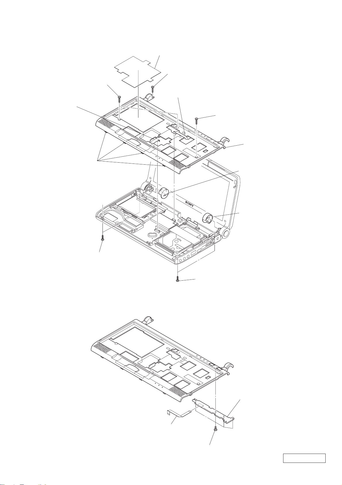
5-1. Main Section
207
54
The components identified by mark 0 or
dotted line with mark 0 are critical for safety.
Replace only with part number specified.
Les composants identifiés par une marque
0 sont critiques pour la sécurité.
Ne les remplacer que par une pièce portant
le numéro spécifié.
52
B5
22
B11
23
24
B5
25
B11
26
Ref.No. Part No. Description
1 A-8066-204-A SWX-62 MOUNT
2 1-794-957-11 FFC (MBX45-SWX62)
3 4-643-063-01 BUTTON, POWER
4 4-648-579-01 LED (KEY BOARD)
* 5 4-648-584-02 RETAINER, SPEAKER
6 1-529-886-11 SPEAKER (30X15 WITH HARNESS)
7 4-648-697-01 SHEET (SPEAKER), ADHESIVE
8 1-791-607-12 FFC (MBX-SW2)
9 4-648-580-01 LED (POWER)
10 A-8066-206-A SWX-63 MOUNT
12 X-4622-964-1 REST SUB ASSY, PALM
13 1-772-335-21 SENSOR MODULE, CURSOR
14 1-791-606-11 FFC (MBX-TP1)
15 1-418-674-23 KEY BOARD UNIT
17 1-763-589-11 FAN WITH HEATSINK
18 1-793-637-11 CONNECTOR, PC CARD (EJECTOR)
* 19 4-648-856-01 SHEET (T), INSULATING
22 1-791-650-11 SUBSTANCE, PRINT PWB SIMPLE
* 23 4-643-048-12 BRACKET (L), HDD
24 1-794-958-11 FFC (MBX45-CNX108)
25 A-8066-145-A ASSY HDD 12.0GB (S)
* 26 4-643-049-12 BRACKET (R), HDD
27 1-959-997-21 HARNESS, MODULAR
28 1-791-608-11 CONNECTOR, HARNESS WITH (DC)
29 4-648-550-01 ESCUTCHEON (R)
31 A-8066-200-A CNX-108 COMPLE
32 4-643-040-01 COVER (L), MAIN
34 4-643-041-01 COVER (R), MAIN
35 4-636-934-01 SPACER (SPRING)
36 4-635-956-01 SPRING (B), COMPRESSION COIL
12
B1
66
B2
38 X-4623-005-2 CABINET SUB ASSY, BOTTOM
39 4-635-946-11 FOOT
40 4-643-028-11 LID, MEMORY
41 A-8047-772-A MBX-45 J/UC ASSY (S)
42 A-8066-571-A IFX-128 COMPLE
43 4-643-811-03 SHEET (IFX), INSULATING
44 1-756-038-21 BATTERY, NICKEL HYDROGEN
45 4-643-046-01 BLIND, HOLE
46 4-648-575-02 SHEET (T), THERMAL
47 4-648-586-01 SHEET (M), BLIND
48 X-4623-006-1 ESCUTCHEON (L) SUB ASSY
50 4-643-050-02 SPRING, TORSION
52 4-648-548-21 LABEL, ID
* 54 4-646-035-01 HEATSINK (CARD SLOT)
58 4-645-941-01 GASKET (RING)
62 4-648-546-01 WINDOW (M)
63 4-651-288-01 SHEET (BOARD), BLIND
64 4-651-484-01 SHEET, EMI
65 4-651-287-01 SPACER (CARD)
66 4-640-515-21 GASKET
B1 4-639-112-01 SCREW M2X4
B2 4-644-002-21 SCREW M2 (SB) (2X6)
B4 4-644-002-01 SCREW M2 (SB) (2X4)
B5 4-635-301-01 SCREW M3X4
B6 4-644-637-11 GRIP, M2 EG (2X8)
B7 7-628-253-35 SCREW +PS 2X8
B10 4-645-214-01 GRIP, M2 (2X3)
B11 4-644-002-31 SCREW M2 (SB) (2X5)
To paste the thermal sheet (T) (46) to the fan with
*
heatsink, warm the thermal sheet (T) adequately until it
becomes soft.
For further information, refer to the removal (page 1-7).
B6
50
19
62
43
58
40
B6
A
32
B10
39
B6
28
38
B11
45
34
29
31
B10
B2
27
35
36
B11
13
C
B10
B2
C
7
6
10
5
B1
9
8
B
14
2
15
18
17
B2
47
45
46
4
3
1
B1
65
64
63
B4
B7
B
A
48
B11
44
41
42
Confidential
5-1 5-2
PCG-C1VN (UC)
Page 22

5-2. LCD Section
B11
104
101
B2
102
105
106
B4
130
108
B8
B10
107
109
110
A
B8
111
129
B
131
112
124
113
A
B9
121
B4
B4
114
123
115
B
127
122
116
116
125
119
120
126
B4
117
118
Ref.No. Part No. Description
101 X-4623-091-1 COVER ASSY, HINGE
102 4-648-046-01 RUBBER (LOWER), BLIND
103 4-643-076-01 RUBBER (RIGHT), BLIND
104 4-643-077-01 RUBBER (LEFT), BLIND
105 X-4622-406-3 BEZEL ASSY
106 4-644-102-01 INSULATOR (UPPER), MICROPHONE
107 A-8046-178-A LCD 1210 ASSY (S)
108 X-4622-314-1 COVER ASSY, MICROPHONE
109 4-643-033-02 HOLDER, MICROPHONE
110 4-643-080-01 RING (F)
111 4-643-066-03 HINGE (C)
112 4-643-067-11 CABINET, MICROPHONE
113 4-643-034-01 NUT (MIC), PLATE
114 4-643-079-02 BEARING (C)
115 4-643-035-01 LATCH (L)
116 4-643-051-01 SPRING, COMPRESSION
117 X-4623-099-1 HOUSING ASSY
118 4-643-081-11 HINGE (LCD)
119 1-476-365-11 INVERTER UNIT
120 4-643-064-02 INSULATING SHEET (INVERTER)
121 1-960-040-12 HARNESS, LCD
122 A-8047-774-A CCD SD22 ASSY (S)
123 4-644-103-01 INSULATOR (UNDER), MICROPHONE
* 124 4-645-340-01 GUARD, CABLE
125 4-643-029-01 LATCH (R)
126 4-643-072-02 LEVER, SWITCH
127 4-643-038-01 CLAMP
129 4-643-812-11 PLATE (MICROPHONE), BLIND
130 4-646-976-02 CUSHION (LATCH)
131 4-651-914-02 TAPE (MICROPHONE)
B2 4-644-002-21 SCREW M2 (SB) (2X6)
B4 4-644-002-01 SCREW M2 (SB) (2X4)
* B8 4-640-695-11 BOLT (M2.6), SPRING
B9 3-318-382-21 SCREW (1.7X3), TAPPING
B10 4-645-214-01 GRIP, M2 (2X3)
B11 4-644-002-31 SCREW M2 (SB) (2X5)
Do not dismantle the CCD SD22 assy (122).
*
For example, removing the connector.
When mounting the ring (F) (110), align markings of camera
*
(side of gear) and groove of ring (F).
If disintegrated, do not turn ring (F) (110).
*
Focus adjustment is off.
Confidential
PCG-C1VN (UC)
B11
103
B2
102
101
5-3 5-4
Page 23

5-3. Accessories
202
Display Adaptor (1)
Ref.No. Part No. Description
ACCESSORIES
***********
202 1-757-026-11 CABLE, VGA
0 203 1-418-518-21 ADAPTOR, A.C.
204 1-756-074-21 BATTERY PACK, LITHIUM ION
0 206 1-782-614-31 CORD, POWER
207 4-643-958-01 CAP (IN BAG), SENSOR
209 1-765-080-31 CORD, CONNECTION
210 A-8056-432-A EM-33 MOUNTED PWB
203
AC Adaptor
204
Battery Pack (1)
206
Power Cord (1)
4-650-622-11 WELCOME MAT, C1
4-650-626-11 USER GUIDE, C1
4-650-629-11 QUICK START, C1
The components identified by mark 0 or
dotted line with mark 0 are critical for safety.
Replace only with part number specified.
Les composants identifiés par une marque
0 sont critiques pour la sécurité.
Ne les remplacer que par une pièce portant
le numéro spécifié.
207
Spare Cap
(for Stick) (2)
209
AV Connecting Cable
210
EM-33 Mounted PWB
Confidential
5-5 PCG-C1VN (UC)
(END)
Page 24

PCG-C1VN (UC)
PCG-C1VN (UC)
9-872-126-11
Sony Corporation
XXX
– 34 –
9-872-126-11
2000J0500-1
This manual and the constituent data may not be
replicated, copied nor reprinted in whole or in part
without prior written authorization of Sony Corporation.
English
2000J0500-1
Printed in XXX
© 2000 Sony Corporation
 Loading...