

Page 1

Welcome.......................................................9
Using Your VAIO Computer ...... ...............1 1
Using the Keyboard...................................................12
Functions of the keyboard keys .........................................13
Combinations and functions with the Windows key .........14
Indicators ...........................................................................15
Combina t i o n s a n d fun c t i o n s w i t h the F n key . .............. .....16
Using VAIO Action Setup........................................19
Using the Jog Dial Control........................................20
Launcher mode ..................................................................20
Guide m o d e............................ ............................................21
Using the Jog Dial control with Sony software.................21
Using the Jog Dial control with other software .................22
Interna l timer..... .................... .............. .............. .................23
Using Memory Stick Media......................................24
Types o f Me m o ry St i c k m e d i a..................... ......................24
Notes on using Memory Stick media.................................26
Using PC Cards.........................................................28
To insert PC card...............................................................28
To remove a PC Card while your computer is on..............29
Notes on PC Cards .............................................................29
Using Power Saving Modes......................................31
Norma l mo d e .. .............. .............. .............. .................... .....3 1
Standby mode ....................................................................31
Hibernate mod e.......... ....................................................... .3 1
Notes on power saving modes...........................................32
Connectin g a Telep hon e Cab l e ................ ................33
To connect a telephone cable .... .......... .......... .......... ...........33
Connectin g to a LAN........... .......... ...........................34
To set up a net w o rk........... .............. .............. ..................... 3 5
1
Page 2

Change text in this var iable definition to docum ent title.
Connecting t o a Wirel e ss LAN.......... ................ .......36
Turnin g O n Wire l e ss LAN................................................36
The Wireless LAN Access Point ...................................... 36
Communicating with an Access Point (infrastructure)..... 37
Communicating without an access point (ad-hoc)............ 38
Turning Off Wireless LAN............................................... 40
Notes on u si n g W i re l ess LAN .......................................... 40
Connecting Peripheral Devices ...............41
Connecting a Floppy Disk Drive ..............................42
To connect a floppy disk drive.......................................... 42
To insert a floppy disk into the floppy disk drive............. 43
To remove a floppy disk from the floppy disk drive........ 44
To disconnect a floppy disk drive when the computer is on.
44
To carry an floppy disk drive.......... .................... .............. 45
Notes on handling floppy disks......................................... 45
Connecting a PC Card Bus Drive .............................46
To connec t a n opt i c al drive............. .............. .................... 46
To insert a disc.................................................................. 47
To remove the drive.......................................................... 48
Notes on CD and DVD discs............................................ 49
Connecting an i.L INK Opt i cal Disc Dri ve...............50
To connec t a n i. LINK optical disc dr i v e............. .............. 5 0
To disconnect an i.LINK optical disc drive...................... 52
Notes on using i.LINK optical disc drives........................ 52
Connecting a USB Mouse or Keyboard ...................53
To connect a USB mouse or keyboard.............................. 53
Connecting a USB Device........................................55
To connec t a USB device.............. .............. .............. ........ 5 5
2
Page 3

Connecting a USB Printer.........................................56
To connec t t o a US B printer ................... .............. ............. 5 6
Connecting an i.LINK Audio-Video Device.............58
To connec t a dig i tal vide o ca mera recorder..................... ..58
Notes on connecting an i.LINK device..............................59
Connecting an External Display................................60
To connec t a co mpu ter disp l ay ............. .............. ...............60
To connec t a pro j e c t o r ........ .................... .............. ............. 6 1
Changing the display when connecting an external computer
display o r p rojector ..... ........ .............. .............. .............. .....62
Connecting wi th an othe r VAI O comput er................63
Connectin g Ext ernal Speakers ....... ......... ..................64
To connect external speakers.............................................64
Connecting a Microphone.........................................65
To connect a microphone........................ .......... ............ ..... 65
To record from a microphone or audio equipment............65
Adjus t in g t h e volume................................................... ......66
Expanding Your Computer Capabilities ...................68
Personal Digital Assistant..................................................68
Wireless LAN Access Point ..............................................68
Wirele ss LAN PC Ca rd.... ..................................................69
Customizing Your VAIO Computer..........71
Displaying the Sony Notebook Setup Screen .... .......72
Sony Notebook Setup tabs.................................................73
Controlling Power Management ...............................74
Viewing th e Power Man a ge m e n t st a t u s i c o n s ................... 7 4
To access PowerPanel Help................ .. .. .. .... .. .. .. .. .. .... .. .....74
Power Management profiles..............................................75
Power Ma n a g e m en t commands .. .................... .............. .....7 7
Conserving battery power..................................................78
3
Page 4

Change text in this var iable definition to docum ent title.
Displaying Battery Info r m ati o n........... .....................79
To display the Battery Information window..................... 79
To displ ay t he Battery Informa t i o n to o l b a r ................... .... 79
To clos e th e Ba t t e ry In fo rmation t o o l b a r.......................... 79
Batte ry i con d escrip t i o n s...... ............................................. 80
Display i n g d e t ailed battery informatio n . .............. ............ 80
Changing the window design of Sony software................ 81
Selecting the D is p lay Mode............... .......................83
To selec t the d i sp l a y mod e...................... .............. ............ 83
Adding Memory.........................................85
Precaution s and Procedures................................. .....86
Typic al expansi o n memory co n fi g u ration........... .............86
Installing a Memory Module ....................................87
Removing a Memor y Mod ule.......................... .........90
Confirming Added Memory Capacity......................92
About the So ft wa re on Your Comp uter...93
Software Overview...................................................93
DVgate application notes..........................................99
Digital video captures ....................................................... 99
Adjusti n g im ag e resolut i o n ............. .............. .............. ...... 99
Hard disk drive partition........................................ ........ ...99
Software Support Information................................101
Sony Service Center........................................................ 103
Using the Recovery CDs ........................105
Application, Driver, and System Recovery CDs....106
4
Page 5

Using Your Recovery CDs......................................107
To use the A p p li cation Recovery CD( s)............. ............. 1 0 7
To use the Driver Recovery CD(s) ..................................108
To use the S y st e m Recovery CD(s)................... ..............109
Troubleshooting......................................113
Troubleshooting Your Computer .. .............. ....... .....114
My computer does not start. ............................................114
My compu t e r sta rts, but a B IOS error a p p ea rs. ............ ...114
My computer starts, but the message “Operating system not
found” appears and Windows does not start....................115
My computer stops responding or does not shut down. ..116
The Power Management setting is not responding..........116
The sound of my computer’s fan is too loud...................117
Why does the System Properties dialog box display a slower
CPU speed than advertised? ............................................117
Troubleshooting the LCD Screen................ ............118
My LCD screen is blank. .................................................118
The image on my connected external display is not centered
or sized pr o p erly. .................. .............. .............. ...............118
I cannot simultaneously display movies, DVD video, or the
Smart Capture (Finder) window on the LCD display and an
external display................................................................118
I want to change the video resolution of my display.......118
Troubleshooting the Mouse and Touchpad.............119
My mouse d o es n o t work.. .............. .............. .............. .....1 1 9
My touchpad does not work properly..............................119
The pointer does not move while I am using the Touchpad or
Mouse...............................................................................119
Troubleshooting Drives, PC Cards and Peripheral De-
5
Page 6

Change text in this var iable definition to docum ent title.
vices........................................................................121
My floppy disk drive icon doesn’t appear even though it is
connected. ....................................................................... 121
My optical drive is not playing my disc properly........... 121
My optic a l d i sc d r ive tray does not op e n ......... ............... 122
I cannot use digital video (DV) devices. The message “DV
equipment seems to be disconnected or turned off” appears.
122
My PC Card i s not worki n g ............................................ 123
Troubleshooting i.LINK devices ............................124
I cannot establish a connection between two VAIO comput-
ers when using an i.LINK cable...................................... 124
Troubleshooting Software........................ .. ..... ....... .125
My software program stops responding or crashes......... 125
When I click an application icon, the message “You must insert the application CD into your CD-ROM (DVD-ROM)
drive” appears, and the software does not start. .............. 125
I cannot use the DVgate software. .................................. 125
My computer’s start-up time seems longer after I have in-
stall e d AOL. What can I d o ?.... ....................................... 125
What software do I use for CD-R/CD-RW software func-
tions? ............................................................................... 126
Troubleshooting the Modem............. ....... ....... ........1 27
My modem does not work. ............................................. 127
My modem connection is slow....................................... 127
Troubleshooting Wireless LAN fun ctions..............128
I cannot use the Wireless LAN functionality.................. 128
The computer cannot connect to a Wireless LAN Access
Point. ............................................................................... 128
I cannot access the Internet............................................. 128
The dat a tr an s f e r speed is slow.... ................................... 129
The communication speed is interrupted or slowed down
6
Page 7

when MPEG2 data is transferred.....................................129
Data tran sfers are interru p t e d .. .............. .................... .......129
Troubleshooting Audio ........................ ....... ....... .....131
My speakers have no sound.............................................131
There is noise distortion while listening to music with USB
speakers or USB headphones...........................................131
My microphone does not work........................................132
Troubleshooting Memory Stick Media .............. .....133
Image files do not open even though I insert Memory Stick
media i n t o the sl o t...... ......................................................133
Memory Stick media does not work. I cannot access the re-
movable drive. .................................................................133
Getting Help.............................................1 3 5
Support Options.......................................................135
7
Page 8

Change text in this var iable definition to docum ent title.
8
Page 9

Welcome
Congratulations on your purchase of this Sony VAIO® computer, and
welcome to the VAIO User Guide.
This User Guide prov ides detailed information on all aspects of using
your new VAIO computer, from keyboard functions to preinstalled
software applications.
In the left navigation window, click the topics you want to learn more
about, and that information will be displayed in this main window.
✍ Click here to find the latest updates and supplemental information about your
computer.
9
Page 10

Change text in this var iable definition to docum ent title.
10
Page 11

Using Your VAIO Computer
This section describe s the following aspects of your new computer:
❑ Using the Keyboard
❑ Using VAIO Action Setup
❑ Using the Jog Dial Cont rol
❑ Using Memory Stick Media
❑ Using PC Cards
❑ Using Power Saving Modes
❑ Connecting a Telephone Cable
❑ Connecting to a LA N
❑ Connecting to a Wireless LAN
11
Page 12
Change text in this var iable definition to docum ent title.
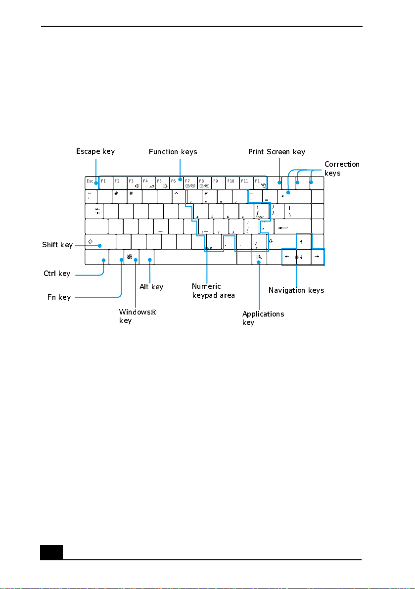
Using the Keyboard
Your keyboard is very similar to a typewriter’s, but your computer keyboard has
additional keys that perform specific c omputer-related tasks.
Keyboard
Shift key
Ctrl key
Fn key
Escape key
Esc
F1 F2 F3 F4 F5 F6 F7 F8 F9 F10 F11 F12
!
2134567890
Q
Tab
A
Caps Lock
Z
Shift
Fn Alt Alt
Ctrl Ctrl
Function keys
$% & ( )
Y
T
R
E
W
H
G
F
D
S
B
V
C
X
Alt key
Numeric
U
I
O
P
J
K
L
<
M
N
>
keypad area
Windows
key
®
Applications
key
Print Screen key
NumLk
Prt Sc
Scr Lk
SysRq
+
Backspace
Enter
?
Shift
Navigation keys
Insert
Pause
Correction
keys
Delete
Break
Home
Page
Up
Page
Down
End
12
Page 13

Using the Keyboard
Functions of the keyboard keys
Key Description
Numeric keypad are a Contains the keys found on a typical calculator. Use the
numeric keypad area to type numbers or to perform
mathematical calculatio n s such as addition and
subtraction. Numbers appear on t he front beveled edge of
the numeric keys. You must press the Num Lock key to
activate the numeric keypad. (When you do so, the Num
Lock indicator lights up. )
Navigation keys Several keys are devoted to moving the cursor on the
screen (the four arrow keys which also function as the
Home, End, Page Up, and Page Down keys).
Correction key s The Insert, Backspace, and Delete keys enable you to
make corrections in your documents.
Function keys The twelve function keys along the top of the keyboard
are used to perform designated tasks. For example, in
many applic at ion s, F1 is th e Hel p k ey. The task asso cia te d
with each functio n key may vary among applications .
Escape key The Esc (Escape) key is used to cancel commands.
Print Screen key The Print Screen key takes an electronic snapshot of the
screen and moves it to the W indows ® Clipboa rd. You can
then paste the screen shot into a document and print it.
13
Page 14
Change text in this var iable definition to docum ent title.
Key Description
Operator keys (Shift,
Ctrl, Alt keys)
Several keys are always use d with at least one other key:
Ctrl, Alt, and Shift. When held down with another key,
the Ctrl (Control) and Alt (Alternate) keys offer another
way to give commands. For example, in many
application s, inst ead of c hoosing the Save command fro m
a menu, you can hold down Ctrl and pres s the S key
(referred to as Ctrl+S). The Shift key operates the same
way as on a typewriter; it is use d to produ ce capita l l etter s
or special symbols, s uch as @ and $.
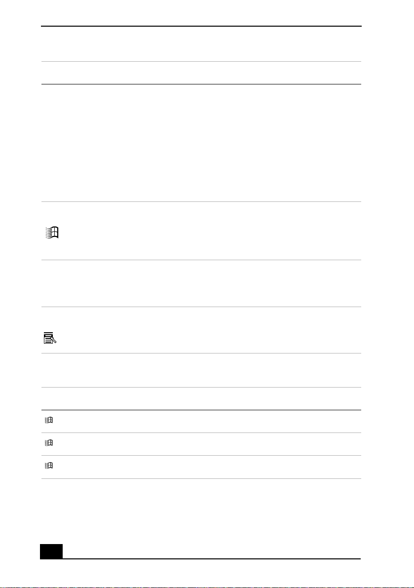
Windows® key The key with th e Wi ndows® logo displ ays t he W indo ws
Start menu; it’s the equivalent of clicking Start on the
taskbar. See “Combinations and functions with the
Windows key” for more information.
Fn key The Fn key is used in combination with other keys to
issue commands. See “Com binations and functi ons with
the Fn key” for more information.
Applications key The Applications key displays a shortcut menu of
context-sensitive choices. Pressing this key is the
equivalent of cl icking the right mouse button.
Combinations and functions with the Windows key
®
Combination Function
+ F1 Displays VAIO® Help and Support Center.
+ Tab Switches the se lected button on the taskbar.
+ E Displays Windows® Explorer.
14
Page 15

Using the Keyboard
Combination Function
+ F Displays the Sea rch window to find a file or fol der. This
is the equivalent of selecting Search from the Start
menu.
+ Ctrl + F Displays the search results window where you ca n
locate other compu ters. This is the equivalent of
selec ti n g Se a r ch , an d th en Co m pu t er s f ro m th e Sta r t
menu.
+ M Minimizes all displayed windows (with Num Lock off).
Shift + + M Returns al l minimized windows to their previous size.
+ R Displays the Run window. This is the equivalent of
selecting Run from the Start menu.
Fn + + Insert Displays the System Properties window. This is the
equivalent of selecting Contro l Pa nel, and then System
from the Start menu.
Indicators
Indicator Function
Power Lights up when th e power to the computer is tu r ned on, flashes in
Standby mode, and turns off when the computer is in Hibern ate
mode or powered off.
Battery
Hard disk Lights up when data is read from or written to the h ard disk drive.
Lights up when the c omputer is usin g bat tery powe r , fl ashe s when
the battery is running out of power, double-flashes when the
battery is charging.
Do not enter Standby mode or turn off the computer when this
indicator light is on.
15
Page 16
Change text in this var iable definition to docum ent title.
Indicator Function
Wireless
LAN
Memory
Stick®
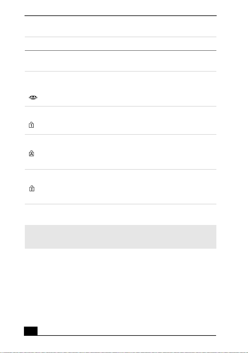
Num Lock Lights up when the number keys are a in the numeric keypad are
Caps Lock Lights up when the le tters appear in uppe rcase as you type. The
Scroll Lock Lights up when the screen scroll s differently. (Exactly h o w i t
Lights up when the Wireless LAN func tion is running.
Lights up when data is read from or written to the Memory Stick
media. (Do not ente r St andby m ode or turn off the computer whe n
this indica tor lig ht i s on.) W hen in dic at or is of f , th e Me mory St ick
media is not being accessed.
active. When indicator is off, the alphanum eric character keys in
the keypad area are active.
Shift key lower s the case of typed letters when Caps Lock is on.
When the indicator is off, the letters appear in lowe r cas e as you
type (unless you hold down the Shift key).
scrolls depends on the specif ic appl icat ion. Thi s funct ion does not
work with all applications.) When indicator is off, information
moves across the displ ay normally.
Combinations and functions with the Fn key
✍ If you switch user identities during a computing session, the Fn+F7 key
functionality (if available on your computer) will be interrupted. To switch to an
external display or monitor, see “Selecting the Display Mo de” for more information.
16
Page 17
Combinations/
Feature Functions
Using the Keyboard
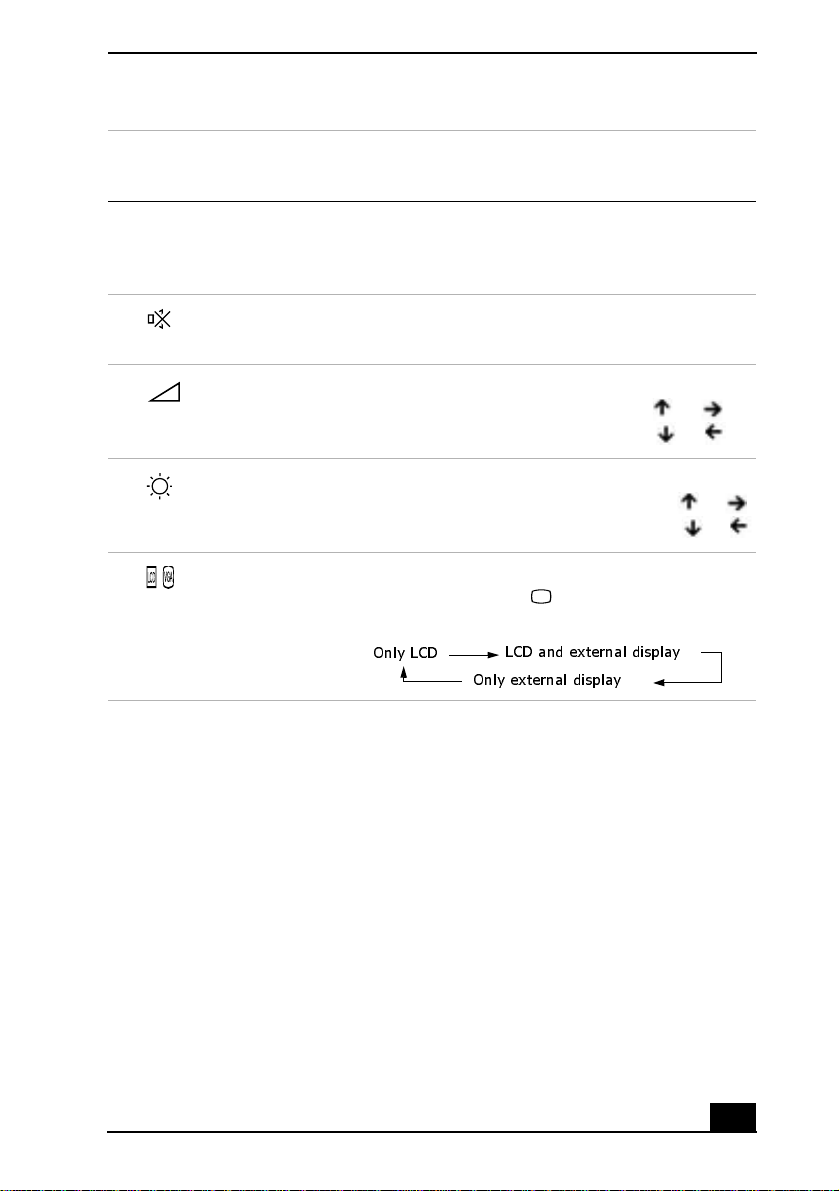
Fn+ (ESC)
Standby
Fn+ (F3)
Speaker switch
Fn+ (F4)
Speaker volume
Fn+ (F5)
Brightness control
Fn+ (F7)
Switch to the
external display
Puts the system into Standby mode, a power
management s tate . To return the system to the ac ti ve
state, press any key on your computer.
Toggles the built-in speaker off and on.
Adjusts the built-in speaker volume.
To increase volume , press Fn+F4, then or .
To decrease volume, press Fn+F4, then or .
Adjusts the brightness of the LCD.
To increase the intensity, press Fn+F5 and or .
To decrease th e intensity, press Fn+F5 and or .
Toggles between the LCD, external display
(connected to the VGA Monitor port), and both
LCD and external display modes.
Only LCD
LCD and external display
Only external display
17
Page 18

Change text in this var iable definition to docum ent title.
Combinations/
Feature Functions
Fn+ (F12)
Hibernate
Fn+B
Bass Boost
Fn+ F Display cont rol. Mi nimiz es and m axim izes th e LCD
Provides for the l owest leve l of po wer consump tion.
When you execute this comma nd, the state of the
system and state of the peripheral devices are
written to the hard disk, and the system power is
turned off. To return the system to the original state,
press the power button briefly to turn on the power.
Toggles the bass-b oos t function off and on. This
feature is available only while using headphones.
screen. If the default display resoluti on is reduced,
this function maximizes the display resolution to fit
the screen size. Ma xi mizing th e d isplay screen
enables you to view the display at a greate r
resolution.
✍ Some functions are not available until Window s® launches.
18
Page 19

Using VAIO Action Setup
Using VAIO Action Setup
VAIO Action Setup manages t he setti ngs for yo ur co mputer’ s Jog Di al™ con trol,
MEMORY STICK
Memory Stick® media, and i.LINK®
TM
*
interface. With VAIO Action
Setup, you can:
❑ Change the Jog Dia l setting
❑ Change the USB de vice connection setting
❑ Change the time setting.
For more information on ch anging the settings us ing VAIO Action Setup, rightclick the Jog Dial control icon or in the taskbar, and click Help Topics.
* i.LINK is a trademark of Sony used only to designate that a produ c t contains an IEEE 1394
connection . T he i.LINK connection may vary, depending on the software applications, operatin g system and compatible i.LINK devic es. All produ cts with an i.LINK connectio n may
not communicat e w ith each other. Refer to the documentation that came with your compatible i.LINK device for informat ion on operati ng conditions and proper connection. Befo re
connecting compatible i.LINK PC peripherals to your system, such as a CD-RW or hard disk
drive, conf irm their op e ra ting s yst em com p at ibility and required op er atin g con di tio ns.
19
Page 20
Change text in this var iable definition to docum ent title.
Using the Jo g Dial C on tro l
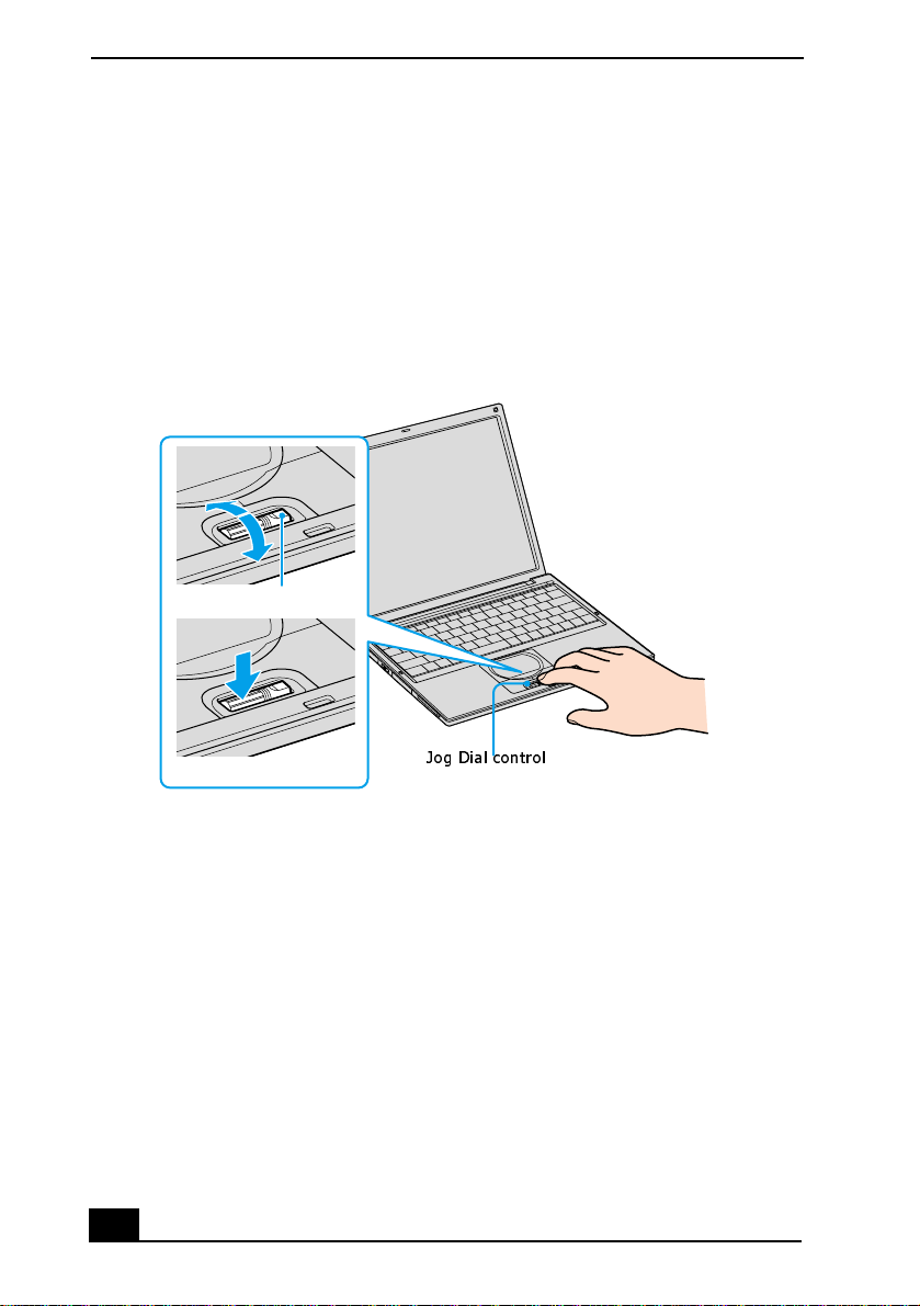
Your computer is equipped with a Jog Dial™ control on the bottom center
portion of the unit. The Jog Dial control enables you to ope n an application,
folder, or document from a predefined list by rotating and pres sing the Jog Dial
control. In addition, when you press the Jog Dial control, you can turn on your
computer automatically and start the selected application or document.
Using the Jog Dial Control
Jog Dial control
The Jog Dial control window always appears in the displ ay. It is either in the
launcher mode or in the guide mode.
For information on how to ch ange the Jog Dial control’s settings, right-clic k the
Jog Di al co nt r ol icon in th e taskbar, an d click He lp Topic s.
Launcher mode
The Jog Dial control window is in launcher mode until a soft ware application is
launched or the Jog Dial control window becomes active. When an arrow is
displayed next to an item in the Jog Dial control window, you can display a
submenu of that ite m by selecting it and press ing the Jog Dial control but ton.
20
Page 21
Using the Jog Dial Control
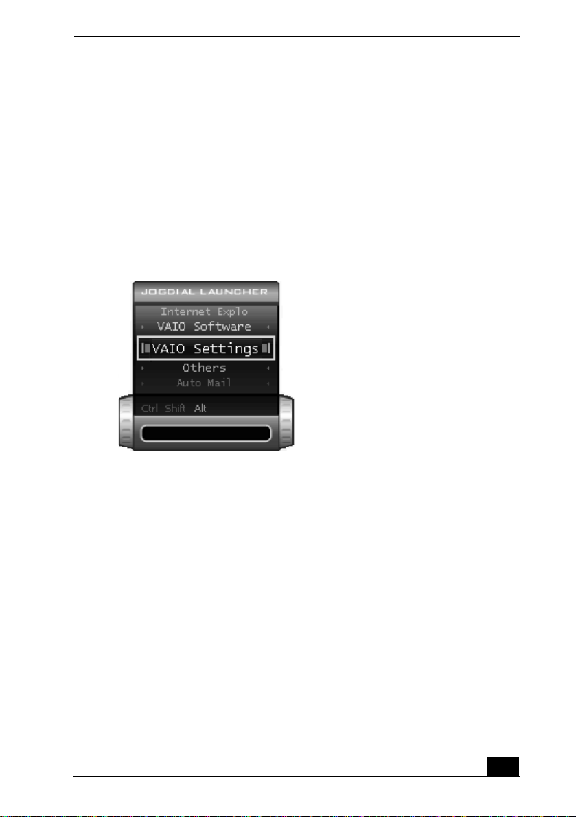
Using Launcher mode
To use the Jog Dial control , double-click the Jog Dial control window or the Jog
Dial control icon in the taskbar. Alternatively, you can press the Jog Dial control
while pressing the Ctrl key on the keyboar d to swi tch to the launcher mode.
1 Turn the Jog Dial control to selec t the item you want, and press the Jog Dial
control. The window swi tches to the guide mode and shows the Jog Dial
control’s function.
Jog Dial Launcher Dialog Box
2 Turn or press the Jog Dial control to use the desired function.
Guide mode
The Jog Dial control window is in the guide mode when software is in use and
the soft ware window is active. Depending on the software you are using, you can
select items from the displayed list using the Jog Dial control. Some Sony
software applications have two modes in List Vi ew, Simple Menu, and Full
Menu. You can switch the mode by pressing the Shift key while turning the Jog
Dial control.
Using the Jog Dial control with Sony software
If Sony software that supports the Jog Dial™ control is active, you can use the
Jog Dial’s functions that are allocated to that software. For more information on
functions allocated to software, see the software application’s online Help.
21
Page 22

Change text in this var iable definition to docum ent title.
Using the Jog Dial control with other software
If the software you are using does not support the Jog Dial control, you can still
perform the following functions:
Action Description
Maximize Window* Press the J og Dial control button to maximize the size
of the active window. Press it again to return to
normal window size.
Minimize W indow* Press the Jog Dial control button to minimize the size
of the active window. Press it again to return to
normal window size.
Finish W indow* Press the Jog Dial control button to close the active
application.
Scroll* Press the Jog Dial control button to begin scrolling
within the ac tive window.
Jog Dial Launcher Press the Jog Di al c ontro l butt on t o r eturn t he J og Dial
control to Jog Launch er mode.
Menu Bar Press the Jog Dia l contro l but ton, an d then us e the J og
Dial control to scroll through the active window’s
toolbar.
* Some softw are ap plic a tio n s do not sup por t the se fun ctio n s .
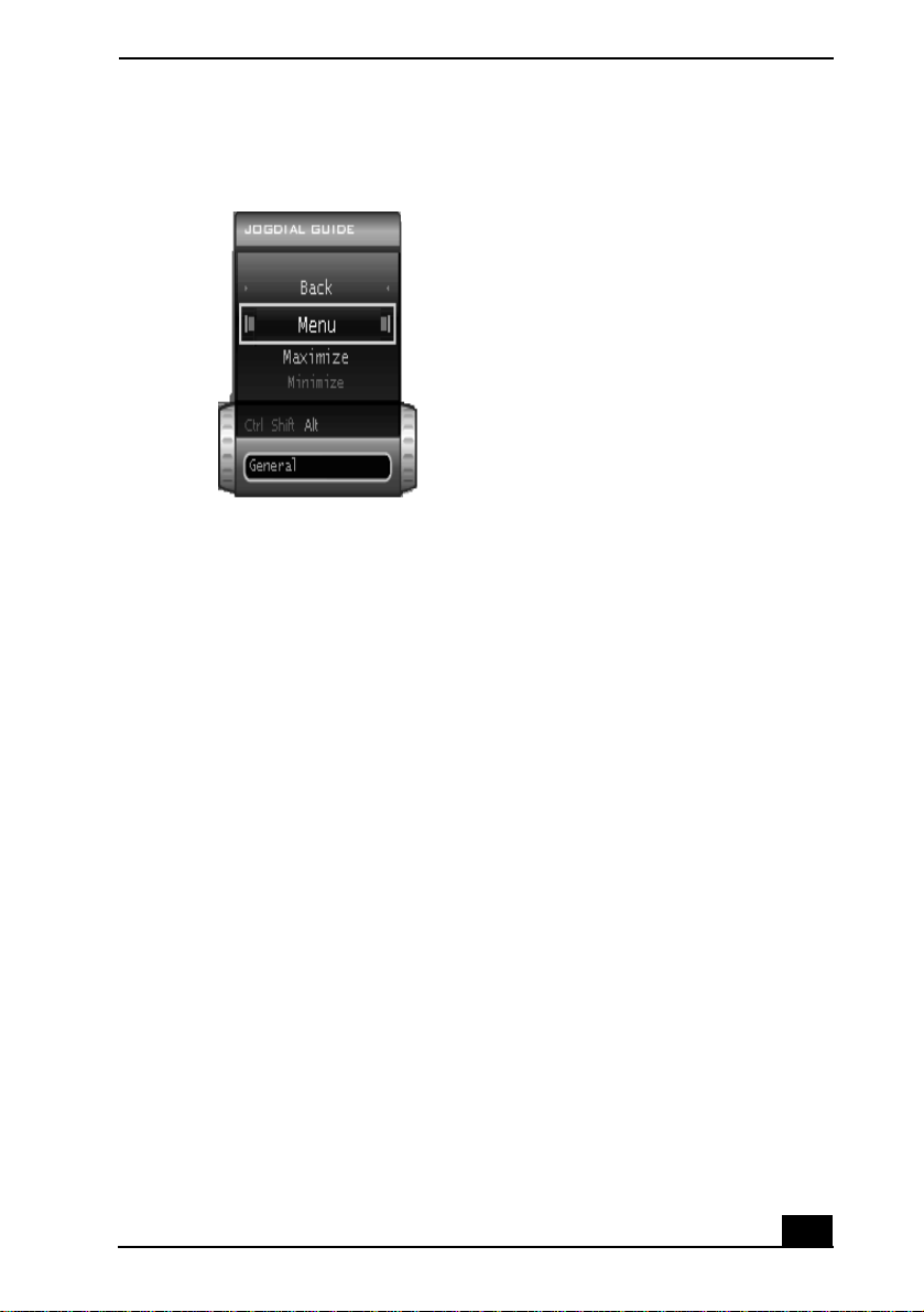
Using a dialog box
When a window such as Screen Properties is active, the Dialog box is displayed
in the Jog Dial™ window. You can select an item in the window by rotating the
Jog Dial control. Pressing the Jog Dial control is the equivalent of pressing Enter.
22
Page 23
Using the Jog Dial Control
Jog Dial Guide Dialog Box
Inte rnal t imer
You can use the internal timer to start an application at a specific time. When set,
the tim e can la u nch application s ev en when th e co mputer is tu r n ed off.
1 Rotate or push the Jog Dial™ control, and select VAIO Action Setup in the
Jog Dial Launcher window.
2 Click Timer from the left menu, and then click the clock icon.
3 Select either Recommended Se ttings, Pro gr am Files, All Files, or Drag &
Drop from the left menu, then select the file or application you want to
launch in the right window.
4 Click Next until the One-Time-Only Setting dialog box appears.
5 Select the D ate and Time and click Next twice .
6 Click Finish, and close the VAIO Action Setup window.
23
Page 24

Change text in this var iable definition to docum ent title.
Using Memory Stick Media
This new compact, portable, and versatil e rec ording medium has a data capaci ty
exceeding th at of a fl oppy disk. The media is specia lly designed for exch anging
and sharing digi tal data with compatible products. Because it is removable, you
can use the media for external data storage.
Types of Memory Stick media
Your computer uses two types of Memory St ick® media:
❑ MagicGate™ Memory Stick media (here aft er referred as MG Memory
Stick media), is provi de d with copyri ght protect ion. (T he MG Memory Sti ck
media are color ed white .)
❑ Memory Stick media, does not have the same copyright protection as
MagicGate. (The Memory Stick media are colored purple.)
For music, which requi res copyright protection, you can only use MG Memory
Stick medi a. You can also use compatible MagicGate dev ices to record and play
back music when they are connected to your computer.
You can store mixed data on the Memory Stick medi a. For exam ple, you can
copy an image onto MG Memory Stick media that alrea dy contains music.
What is MagicGate?
MagicGate t echnology is copyright protection that consists of authentication and
encryption technology. Authentication technology ensures that protected content
is only transferred between complian t devices and media. Prot ected content is
recor d ed and transferred in an encrypt ed format to preven t u n author ized
duplication or playback.
✍ Ensure that the MG Memory Stick media has the M G mark .
To insert a Memory Stick media
1 Hold the Memory Stick media with the label facing up and the arrow facing
toward the Memory Stick® media slot.
2 Carefully insert the Memory Stick media into the slot until it clicks into
place.
24
Page 25
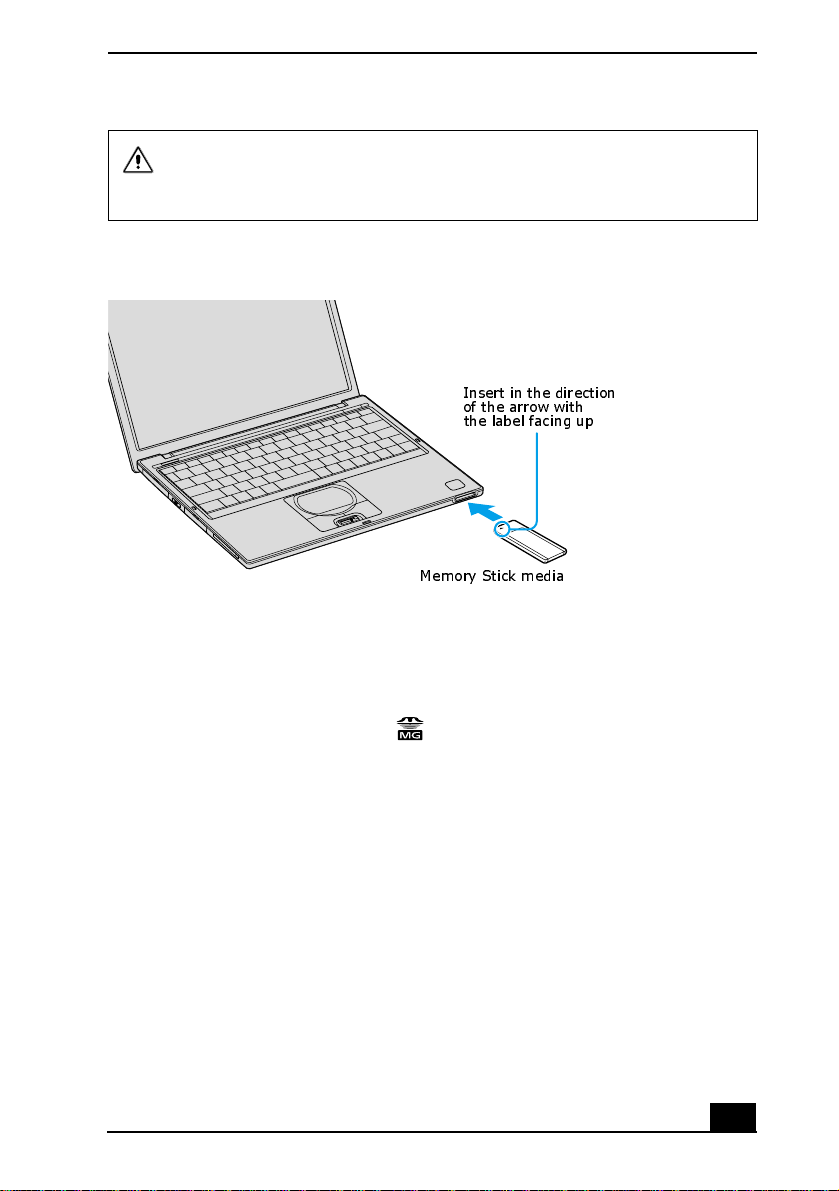
Inserting the media in the wrong direction may damage the connector pins.
To avoid damagi ng the computer or the Memory Stick Media, do not force
the Memory Stick media into the slot.
Inserting Memory Stick
Using Memory Stick Media
Insert in the direction
of the arrow with
the label facing up
Memory Stick media
To view the contents of Memory Stick media
1 Click Start on the Windows® taskbar, and the n My Com puter.
2 Click the Sony Memory Stick
icon. The Sony Memory Stick window
appears, dis playing the contents of your MemoryStick media.
To remove a Memory Stick media
1 Wait a minimum of 10 seconds after the media finishes reading or writing
data before removing it. If the media is removed premature ly, an error
message appear s, prompting you to continue or exit. Reinsert the media into
the slot a nd press Enter to continue. This enables the media to finish reading
or writing data.
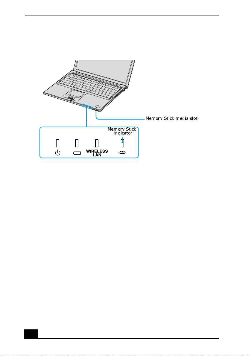
2 Make sure the Memory Stick indicato r is of f. When the indicator is off, th e
Memory Stick media is not being accessed.
25
Page 26
Change text in this var iable definition to docum ent title.
Memory Stick media indicator
Memory Stick media slot
Memory Stick
indicator
3 Push th e m ed i a in to w a rd th e computer.
4 When the media ejects, pull it out. The Memory Stick media may eject
completely from the s lot.
Notes on using Memory Stick media
❑ When the media’s write-protect tab is set to LOCK, you cannot record or
erase dat a.
❑ Before using Memory Stick media, you shoul d back up important data.
❑ You can enjoy video clips tha t you have recorded with compatible Memory
Stick dig ital camcorders.
❑ The media slot accommodates one media at a time.
❑ To copy images from a digital video camera via Memory Stick® media, see
“Connecting an i.LINK Audio-Video Device” for more information.
❑ Only MG™ Memory Stick me dia can be used with copyright protected data
like mu si c.
❑ Do not remove the media or turn off the power while the access light is on.
26
Page 27

Using Memory Stick Media
❑ Do not use the media in locations that are subj ect to static elec tricity or
electri cal noise .
❑ Do not touch the media connec tor with your finger or metallic objects.
❑ Do not attach labels other than the supplied label to a media.
❑ Do not bend, drop, or shock the media.
❑ Do not disassemble or modify the media.
❑ Do not allow the media to get wet .
❑ Do not use or store the media in a location that is subject to:
❑ Extreme ly hi g h temperatu r es, such as in a ca r par k ed in th e su n .
❑ Direct sunlight.
❑ High humidity or place s with corrosive substances.
❑ To prolong the life of the media, use the supplied storage case. See the
instructions supplied with your media for more information on its use.
27
Page 28
Change text in this var iable definition to docum ent title.
Using PC Cards
Your computer includes a PC Card slot, which enables you to connect portable
external devices, such as an optical disc drive.
✍ The PC Card slot accommoda te s a Type I or T ype II PC Card . Thi s slo t is co mpat ib le
with Card Bus. Type III PC Cards are not supported.
To insert PC card
✍ You do not need to shut down the computer before inse rting or removi ng a PC Card.
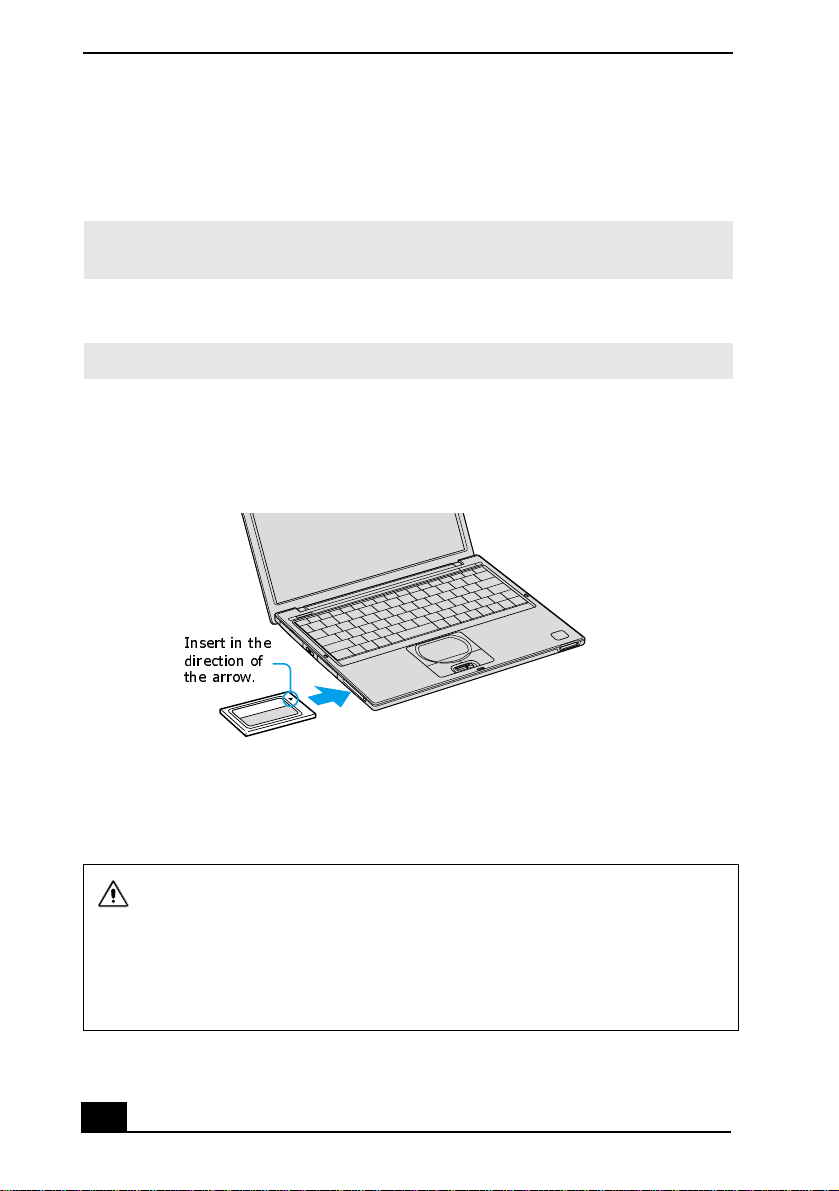
1 Insert the PC Card into the PC Card sl ot with the front labe l facing up.
Inserting PC Card
Insert in the
direction of
the arrow.
2 Gently push the PC Card into the slot until it is firmly seated in the port and
the release button pops out.
Do not force a PC Card into the slot. It may damage the connector pins.
When a PC Card is inserted, do not place your computer in a bag or case.
Pressure or shock to a PC Card may damage your comput er.
Touching the head of the PC Card will not cause damage to the connector
pins, but damage can occur if the head of the PC Card i s sticking out of the
computer while the unit is being transported.
28
Page 29
Using PC Cards
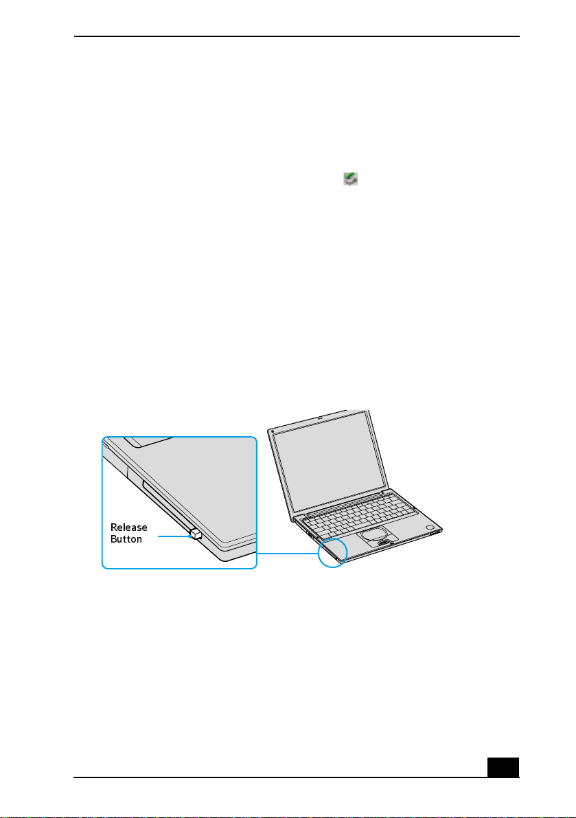
To remove a PC Card while your computer is on
Failure to follow this procedure may result in a malfunction.
1 Before disconnecting this drive, close all active applications to help prevent
data loss.
2 Doub l e - c li ck the Safe ly Re m o v e Hardware icon in th e taskbar. The
Safely Remove Hardware window appears.
3 In the Hardware devices box , select the appropriate PC Card name if it is not
already selecte d, and click Stop. The Stop a Hardware device window
appears.
4 Make sure the appropriate PC Card name is selected, and click OK. A
message appears stating it is safe to remove the hardware.
5 Press the Releas e button. The PC Card pops out.
6 Gently grasp the PC Card and pull it out.
Release Button
Release
Button
Notes on PC Cards
❑ For some PC Cards, if you alternate between normal power operation a nd
the Standby or Hibernate power management modes while the card is
inserted, you may find that a device connected to your system is not
recog n ized. Restart you r system to correct the proble m.
29
Page 30

Change text in this var iable definition to docum ent title.
❑ Some PC Cards may require that you disable idle devices when using the PC
Card. You can use Sony Notebook Setup to disable devi ces. See “Displ aying
the Sony Notebook Setup Screen” for more information.
❑ Be sure to use the most recent software driver provided by the PC Card
manufacturer.
❑ If an exclamation mark (!) appears on the Device Manager tab in th e System
Properties dia log box, remove the software driver , and reinstall it.
❑ You may not be able to use some PC Cards or some fun ctions of the PC Ca rd
with this computer. If you have difficulty inserti ng a card, check that you are
orienting the c ard co rrectly. See the manual supplied with your PC Card for
more information on its use.
30
Page 31

Using Power Saving Modes
Using Power Saving Modes
When you use a battery as the power source for your computer, you can use the
power management settings to conserv e bat tery life. In addition to the normal
operating mode, which enables you to turn off spe cific devices, your compute r
has two di sti nct p ower sav ing mo des: S ta ndb y and Hi be rnate . When usin g ba tte ry
power, the computer automatically enters Hibernate mode when the remain ing
battery charge drops be low 5 percent, regardless of the power management
setting you select.
✍ If the battery level falls below 10 percent, you should either attach the A C adapter to
recharge the batte ry or turn off your computer and insert a fu lly charged battery.
Normal mode
Normal mode is the normal state of your computer when it is in use. The power
indicator displ ays gree n when your compute r is in this mode. To save power, you
can turn off a s p ec if i c de v ic e su ch as th e LC D or th e h ar d dis k .
Standby mode
In Standb y Mode the computer sa ves the current st ate of the system in RAM and
switches off power to the CPU. The amber power indicator flashes in this mode.
To activate Standby mode
1 Press the key combination Fn+Esc. You can also use the PowerPanel™
utility to enter Standby mode.
2 Press any key to return to normal mode.
Hibernate mode
In the Hibernate mode, the state of the system is s aved on the hard disk drive and
power is turned of f. The power indicator is off in this mode.
31
Page 32

Change text in this var iable definition to docum ent title.
To activa te H ibernate mode
1 Press the key combination Fn+F12, or press the power button and release it
immediately. The “ Save t o Disk Manager” screen appears, and th e computer
enters Hibernate mode.
✍ Do not move the computer until its power indicator turns off.
2 Press the power button to return to normal mode.
Notes on power saving modes
❑ Standby uses more powe r than Hibernate.
❑ Standby requires less time than Hibernate to return to normal mode.
32
Page 33

Connecting a Telephone Cable
Connecting a Telephone Cable
You need to connect a telephone cable (not supplied) to register your VAIO®
computer, use online services and the Internet, and use Sony Com puting Support.
To connect a telephone cable
1 Open the port panel on the right side of the computer, and locate the modem
jack.
Plugging in Te lephone Jack
T elephone cable (not supplied)
Modem jack
Port panel cover
2 Plug one end of the tel ephone cable into t he Mo dem ja ck. Make sure i t cli cks
into pl ace.
3 Plug the other end into the wall jack.
✍ Your com puter does not w ork with party lines, cannot be connected to a coin-
operated telephone, and may not work with multiple phone lines or a private br anch
exchange (PBX). Some of these connections may result in excess el ectrical current
and could ca use a malfunction in the internal modem.
If you connect a phone line coming throug h a splitter, the modem or connected
device may not work proper ly.
33
Page 34

Change text in this var iable definition to docum ent title.
Connecting to a LAN
You can connect your computer to 10BASE-T and 100BASE-TX-type Local
Area Networks (LANs) by using the comput er’s Ethernet port. For the detailed
settings and devices needed to connect to the network, ask your network
administrator.
Connecting to LAN
Ethernet
port
34
Warning: Only connect 10BASE-T and 100BASE-TX cables to the
Ethernet port. Do not connect any other type of network cable or a
telephone ca ble . C onnecti ng cables ot her than t hos e lis te d ab ove m ay re sul t
in an electric current overload and could cause a malfunction, excessive
heat, or fire in the port. To connect the unit to the network, contact your
network administrator.
If you enable Wake on LAN, the power saving mode will be switched t o
Standby m ode.
Page 35

Connecting to a LAN
To set up a network
1 From the Start menu, click Control Panel. The Control Panel window
appears.
2 Click Network and Internet Connections. The Network and Internet
Connections window appears.
3 Under “Pick a task,” click “Set up or ch ange your home or small office
network,” depending on your configurat ion. The Network Setup Wizard or
the Location Inform ation dialog box appea r s , depending on your choice.
4 Follow the on-screen instruc tions.
35
Page 36

Change text in this var iable definition to docum ent title.
Connecting to a Wireless LAN
Your computer is equipped with a built-in mini PCI card that allows for wireless
connections. With Sony’s Wireless Local Area Network (LAN) functionality, all
compatible digital device s can communicate freely without cable connec tions. A
Wire less LAN is a net work in which a mobil e user can connec t to a LAN through
a wireless (radio) connection. You can opt to purchase a Wireless LAN Access
Point to set up a LAN.
Turning On Wireless LAN
To enable Wireless LAN functionality, first locate the Wireless LAN switch that
is located on the left side of the computer. Move the switch to the ON position.
The Wireles s LAN indicator on the bottom left front portion of the computer
lights up.
Connecting to a wireless LAN
Wireless LAN
switch
Wireless LAN
indicator
The Wirele ss LAN Access Poin t
The Wireless LAN Access Point, also called the access point, is design ed for
building a Wireless LAN environmen t. If you purchase an access point , you can
easily build a wire less LAN environment by plugging the access point into an
AC power outlet, and usi ng the provided software wit h com patible devices.
Because a wireless LAN configuration requires no wiring, you can operate
multiple computers more freely than ever before .
36
Page 37

Connecting to a Wir eless LAN
You can also connect an access point to a telephone line, Integra ted Services
Digital Networ k (ISDN) route r , c able mode m, or Digita l Subs cribe r Line (xDSL)
modem to share acce ss to the Internet amon g multipl e computers.
Communicating via Wireless LAN Access Point
Access point (not supplied)
✍ For information on available Sony products, go to:
http://www.sonystyle.com/wirelesslan.
Communicating with an Access Point (infrastructure)
An infrastructure network is one that extends an existing wired local network to
wireless devices by providing an access point. The access point brid ges the
wirele s s an d wi r ed LA N , an d act s as a central co nt r o ll er for th e Wire l e s s LA N .
The access point coordinates transmis sion and reception from multiple wireless
devices within a specific range.
To communicate with an access point [[Cannot confirm steps yet]]
1 Locate the Wireless LAN switch that is located on the left side of the
computer. Move the switch to the ON position.
2 From the Start menu, point to Connect To, and click Wireless Net work
Connection. The Wireless network Connection Status window appears.
3 Click Network and Internet Connections, an d then Network Connections.
4 Double-click the W ireless Network Connection icon. The Connect to
Wireless Network dialog box opens.
37
Page 38

Change text in this var iable definition to docum ent title.
Connecting to a wireless LAN
5 Select a network from the Available Networks list box.
6 Click Connect.
Communicating without an access point (ad-hoc)
An ad-hoc network is one in which a local network is created only by the
wireless devices themselves, with no other central controller or access point.
Each device communicates di rectly with other devices in the network. You can
set up an ad-hoc network easily at home.
To communicate without an access point [[Cannot confirm steps yet]]
1 Turn on the Wireless LAN switch located on the left side of the computer.
The Wireles s LAN indicator on th e bott om left front port ion of the computer
lights up. See “Turning On Wireless LAN” for more information.
2 Click Start on the taskbar, point to Connect To, and click Wireless Network
Connection.
38
Page 39
Connecting to a Wir eless LAN
3 Click View Avail able Wireless Networks. The Connect to Wireless Network
dialog box appears.
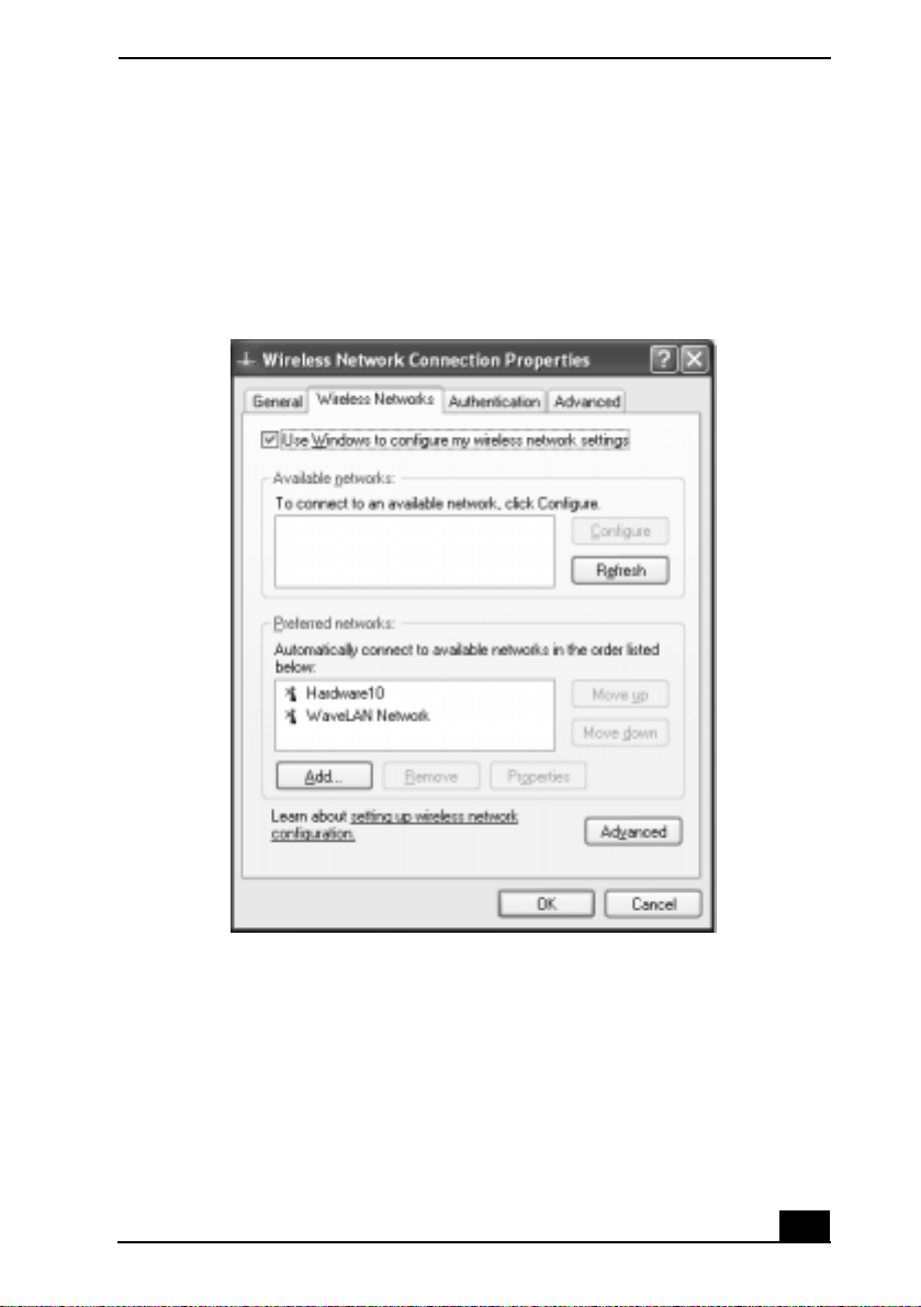
4 Click the Advanced button. The Wir eless Network Connection Properties
dialog box appears.
Setting Wireless Network Connection Properties
5 Select the Wireless Networks tab.
6 Click the Add... button. The Wireless Network Properti es dialog box
appears.
7 Enter a Network name (SSID). Choose a 6-digit name.
8 Check the box to select Data encryption (WEP enabled).
39
Page 40

Change text in this var iable definition to docum ent title.
9 Check the box to select Network Authentication (Shared mode).
10 Clear the box to deselect the option “The key is provided for me
automatically.” Some information boxes become visible.
11 Fill in the Network key. Choose a 5-digit name.
12 Click OK. Your new Network name appears in the Pref erred networks
window.
13 Click Advanced. The Advanced dialog box appears.
14 Select the option “Compute r-to-computer (ad hoc) networks only.”
15 Click Close.
16 Click OK.
Turning Off Wireless LAN
To turn off Wireless LA N f un c tional it y, locat e the Wirele ss LA N s w it ch th at is
located on the left side of the computer, above the PC Card slot. Move the switch
to the OFF position. The Wirele ss LAN indicator on the bot tom left front portion
of the comp u ter turns off.
Turning off the Wir eless LAN funct ionality while accessi ng remote
documents, files, or resources may result in data loss.
Notes on using Wireless LAN
❑ Sony Wire les s LAN devices support the IEEE802.11b standa rd. Devices
connecting to a Wireless LAN using the IE EE802.11a standard cannot
connect to devices using the IEEE802.11b standard.
❑ Wireles s LAN communication occurs on divided frequency bands known as
channels. Third-pa rty W ire less LAN Access Point cha nnels may be prese t to
different channels from Sony devices.
❑ If using a Wireless LAN Access Point, refer to connectivity information
contained in those instr uctions.
40
Page 41

Connecting Peripheral Devices
You can add functionality to your notebook by connecting a variety of
peripherals, as discussed in the following sections:
❑ Connecting a Floppy Disk Drive
❑ Connecting a PC Card Bus Drive
❑ Connecting an i.LINK Optical Disc Drive
❑ Connecting a USB Mouse or Keyboard
❑ Connecting a USB Devi ce
❑ Connecting a USB Pri n ter
❑ Connecting an i.LINK Audio-Video Device
❑ Connecting an Ex ternal Display
❑ Connecting with another VAIO computer
❑ Connecting Ex ternal Speakers
❑ Connecting a Mic rophone
❑ Expanding Your Computer Capabi lities
41
Page 42

Change text in this var iable definition to docum ent title.
Connecting a Floppy Disk Drive
You can connect a floppy disk drive (not supplied) to a USB port on your
computer, port replicator, or docking station.
To connect a floppy disk drive
✍ You do not need to shut down your computer before connecting or disconnecting a
floppy disk drive.
Before disconnecting the floppy disk drive, see “To disconnect a floppy disk drive
when th e com p uter is on” for more information.
1 Before connecting this drive, close any active applications to he lp prevent
data loss.
2 Plug the USB connector into the USB port. The logo on the floppy disk
drive should face upward.
42
Page 43

Connecting an Floppy Disk Drive
Connecting a Floppy Disk Drive
Floppy disk drive
(not supplied)
USB ports
USB connector
To insert a floppy disk into the floppy disk drive
1 Hold the floppy disk with the label facing up.
2 Gently push the floppy disk into the drive until it clicks into place.
43
Page 44

Change text in this var iable definition to docum ent title.
Inserting a Floppy Disk
Floppy disk
Floppy disk drive
To remove a floppy disk from the floppy disk drive
1 Close all applications that we re opened from the disk an d wait for t h e LED
indicator to turn off.
2 Push the Eject button, and remove the disk.
✍ Do not push the Eject button when the LED indicator is turned on; otherwi se, you
may lose da ta .
Removing a Floppy Disk
Eject button
LED indicator
To disconnect a floppy disk drive when the computer is on
1 Before disconnect ing this d rive , clo se any ac ti ve appl icati ons to help pre ven t
data loss.
2 Dou bl e- click th e Sa f ely Remov e Hardware icon in th e ta s k b ar. The
Safely Remove Hardware window appears.
44
Page 45

Connecting a Floppy Disk Drive
3 In the Hardware devices box, select Y-E Data USB Floppy, and click Stop.
The Stop a Hardware device window appears.
4 Make sure Y-E Data USB Floppy is selected, and click OK. A message
appears stating it is safe to remove the hardware.
5 Unplug the floppy disk driv e from the co mpu ter, port re plicator , or docking
station.
To carry an floppy disk drive
❑ Fold the fl oppy disk drive cable and conn ector into the s ide compartment on
the floppy disk dri ve.
Carrying an Floppy Disk Drive
Notes on handling floppy disks
❑ Do not open the shutter manually and touch the surface of the floppy disk.
❑ Keep floppy disks away from magn ets.
❑ Keep floppy disks away from direct sunlight and other heat sources.
45
Page 46

Change text in this var iable definition to docum ent title.
Connecting a PC Card Bus Drive
[[Cannot confirm steps yet]]
You can use an optional optical drive with your computer. If you use an optiona l
drive when your computer i s running on battery power, the battery life will be
shorter. The drive draws power from the computer through a PC Card.
If you connect a non-Sony DVD drive to your VAIO® computer, the DVD
playback may not function properly. The DVD software (supplied) must
be installed to play a DVD.
For best performance, use a Sony compatible DVD drive .
To connect an optical drive
Procedures for connecting an optical dri ve may vary , depending on the specific
drive you purchase. See the manual supplied with your optical drive for more
information on it s installation and use.
✍ You can connect an optical drive while th e com puter is on. For specif ic instructions
on using you r supplied Application, D river, and System Rec overy CDs, see “Using
Your Recovery CDs” for more information.
1 Remove the PC Card from the bottom side of the optical drive .
Removing PC Card
2 Insert the PC Ca rd into the PC Card slot with the logo f acing up. See “Us ing
PC Cards” for details.
46
Page 47

Connecting a PC Card Bus Drive
Inserting PC Card
Make sure logo faces up
✍ A protective cover is attached to the lens of the optical drive at the factory. Before
using the optical dri ve, remove the protectiv e cover.
To insert a disc
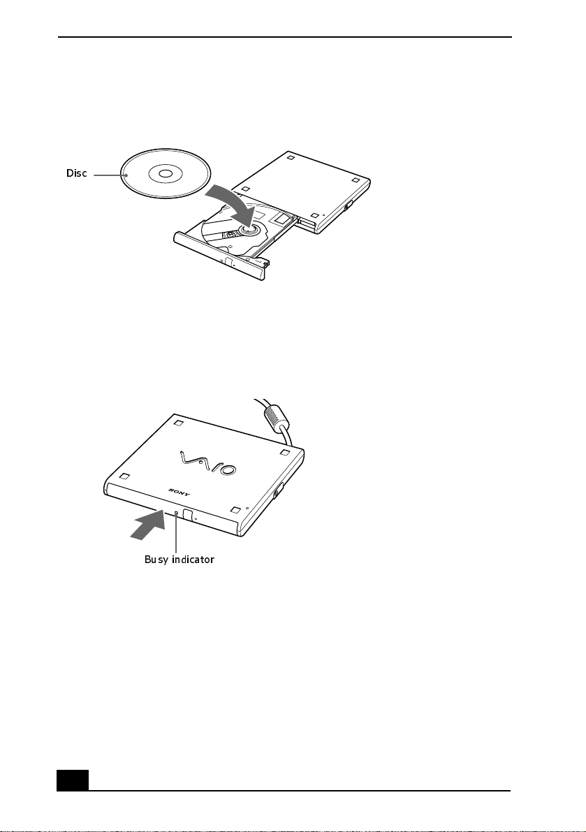
1 Press the Eject button. The disc tray slides out.
Optical Drive
Eject button
2 Place the dis c in the tray with the label fac ing up.
3 Push the disc onto the hub un til the disc clic ks into place.
47
Page 48
Change text in this var iable definition to docum ent title.
Inserting Disc
Disc
4 Close the tray b y pus hing i t i n gentl y. The Busy indicato r on t he drive flash es
while your computer is reading data from the disc.
Flashing Busy Indicator
Busy indicator
To remove the d r iv e
Remove the PC Card from the computer. See “To disconnect a floppy disk drive
when the computer is on” for more information.
48
Page 49

Connecting a PC Card Bus Drive
Notes on CD and DVD discs
Handling CD or DVD discs
❑ Do not touch the surface of the disc.
❑ Do not drop or bend the disc.
❑ Avoid using adhe sive labels to identify your discs. Adhesive labels may
come off while the disc is in use in your optical drive a nd damage to the unit.
Cleaning CD or DVD discs
❑ Fingerprints and dust on the surface of a dis c may cause data reading er rors.
Proper care of the disc is essential to maintain its reliability. Do not use
solvents such as b en zine, t h in n er , commercially ava ilable cleaners or antistatic sp r ay, as they m a y d a mage the disc.
❑ For normal clean ing, hol d t he dis c by it s edge and use a soft c loth t o wipe the
surfa ce from the center o u tward.
❑ If the disc is badly soiled, moisten a soft cloth with water, wring it out well,
and use it to wipe the surface of the disc from the center out. Wipe off any
remaining moisture with a dry soft cloth.
49
Page 50

Change text in this var iable definition to docum ent title.
Connecting an i.LINK Optical Disc Drive
You can connect an i.LINK®* optical disc drive to you r computer, port
replicator, or docking station. This computer is preinstalled with software that
enables you to create CDs and play DVD movies. The i.LINK optical disc drive
draws power from the computer th rough a peri pheral cable. This peripher al cable
connects to both the i.LINK port and DC OUT jack on the computer.
†
✍ If you use an optional drive when your computer is running on battery power, the
battery life will be shorter .
To connect an i.LINK optical disc drive
1 Before connecting this drive, close any active applications to he lp prevent
data loss.
2 Turn on power to the comput er.
3 Insert the L-shaped conne ctor of the peripheral cable (supplied with the
i.LINK drive) in t o th e match in g ja ck on th e i.LINK dr ive. Se cu r e th e
connector by turning the LOCK device clockwise.
* i.LINK is a trademark of Sony us ed only to designat e that a product contains an IEEE1394
connection. The i.LINK connection may vary, depending on the software applications, operating system and compatible i.L I N K devices. All products with an i.LINK connection may
not communicate w ith each other. Refer to the documentation that came with your compatible i.LINK device for information on operating conditions and proper connection. Before
connecting compatible i .LINK PC pe ripherals to your sys tem, such as a CD-R W or har d disk
drive, confirm their operating system compatibility and required operating conditions.
† If you connect and use an option al drive when your computer is run ning on battery pow er,
the battery life w ill be reduced.
50
Page 51

Connecting i.LINK optical disc drive
L-shaped cable
connector
i.LINK cable
DC OUT jack
i.LINK port
Connecting an i.LINK Optical Disc Drive
4 Insert the straight-shaped, two-prong connector of the peripheral cable into
both the computer’s i.LINK port and DC OUT jack.
5 The i.LINK drive’s power indicator lights up, and the computer
automatically dete cts and identi f ies the connected drive.
6 Click Start on the Windows® operat ing system taskbar, and select My
Computer to verify that an icon for the i.LINK optica l disc drive was added
in the wi ndow.
✍ The Sony i.LINK optical disc drive is compatible only with certain Sony VAIO®
PCG series computers pre installed w ith Microsoft® Windows® XP Home Edition or
Professional.
51
Page 52

Change text in this var iable definition to docum ent title.
To disconnect an i.LINK optical disc drive
1 Before disconnect ing this d rive , clo se any ac ti ve appl icati ons to help pre ven t
data loss.
2 Dou bl e- click th e Sa f ely Remov e Hardware icon in th e ta s k b ar. The
Safely Remove Hardware window appears.
3 In the Hardware devices box, select the appropriate i.LINK drive if it is not
already selected, and click Stop. The Stop a Hardware device window
appears.
4 Make sure th e ap propriate i.LIN K d rive is s elected , an d click OK . A
message appears stating it is safe to remove the hardware .
5 Unplug the i.LINK optical disc drive from the computer, port replicator, or
docking station.
Notes on using i.LINK optical disc drives
❑ You can use the supplied Application Recovery, Driver Recovery, and
System Recovery CDs with an i.LINK optical disc drive. See “Application,
Driver, and System Recovery CDs” for more information.
❑ Do not use a n optional i.LINK optical disc drive and an optio nal optical dis c
drive with PC Card at the same time. Connecting both drives may cause a
system malfunction.
52
Page 53

Connecting a USB Mouse or Keyboard
Connecting a USB Mouse or Keyboard
You can connect a universal serial bus (USB) mouse or keyboard to your
computer, port replicator, or docking station. Make sure th e USB devic e is
compatible wit h the Windows® operating system.
To connect a USB mouse or keyboard
1 Turn off your computer before you connect or disconnect the mouse or
keyboard.
2 Locate the USB port on your computer, port replicator, or docking
station.
3 Plug the mouse or keyboard cable into this port.
✍ You can use a Sony USB mouse (n ot supplied) with this computer . The USB mouse
softwar e driver is pr einstalle d; however, the fir st time you connect a mouse, onscreen in stallati o n in st ru ctions may ap p ea r. Pres s E n te r to co m p le te the on -s cr ee n
instructions.
Connecting a USB Mouse or Keyboard
53
Page 54

Change text in this var iable definition to docum ent title.
✍ See the manual that came with your mouse or keyboard for more information on its
installation an d use.
54
Page 55

Connecting a USB Device
Connecting a USB Device
You can connect a universal serial bus (USB) device, such as speakers or
microphones, to your com puter, port replicator , or do cking s tati on. Make sure the
USB device is compa tible with the Windows® operati ng system.
To connect a USB device
1 Locate the USB port.
2 Plug the USB cab le (not suppli ed) int o this port, and plug the oppo site end of
the cable into the USB device, if it is not alre ady connected.
Connecting a USB Device to a USB Port
To U S B ports
✍ See the manual that cam e with your USB device for more information on its
insta lla ti on an d use.
55
Page 56
Change text in this var iable definition to docum ent title.
Connecting a USB Printer
You can connect a universal serial bus (USB) printer to your compu ter, port
replicator, or docking station. Make sure the USB device is compatible with the
Windows® operating system.
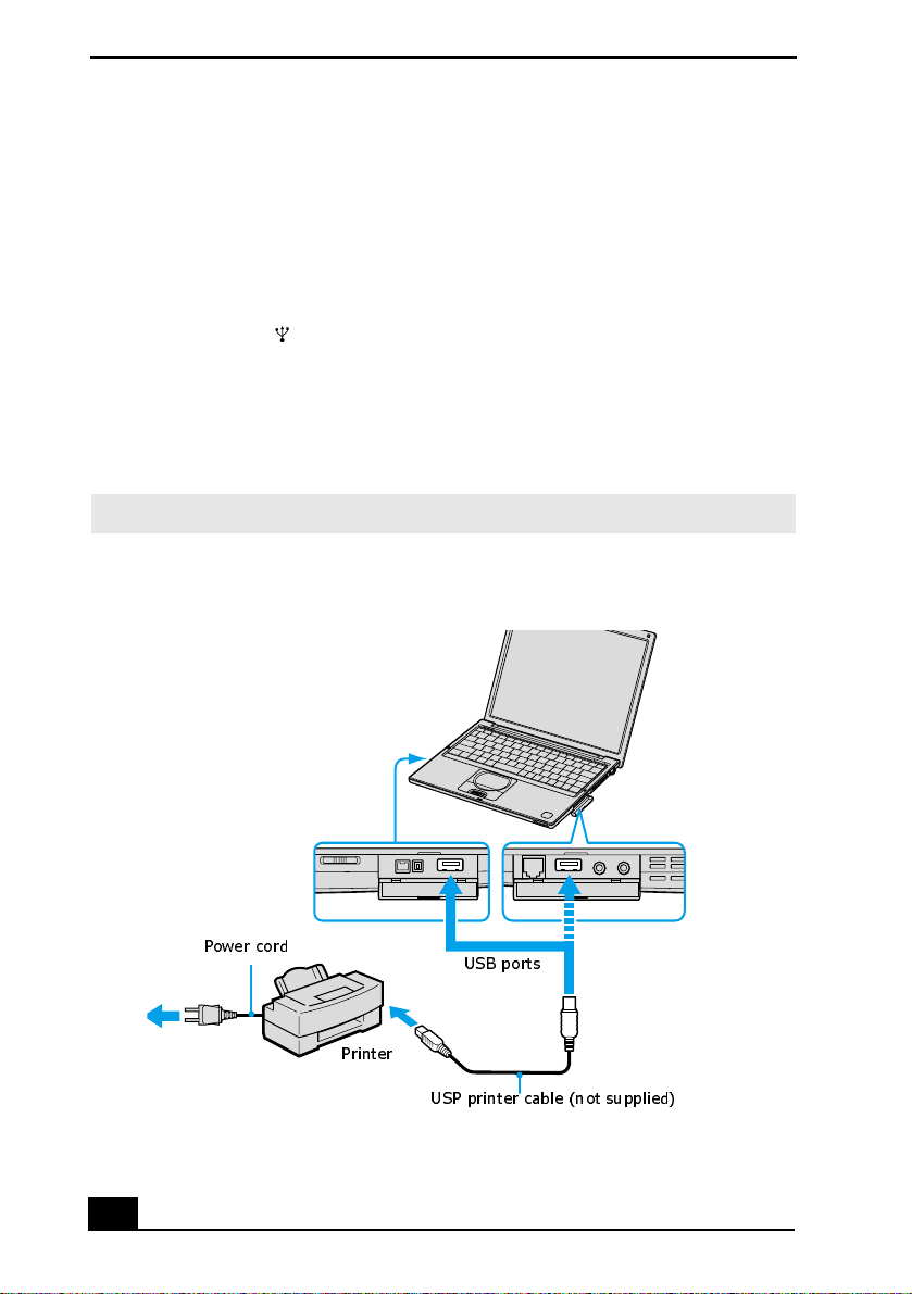
To connect to a USB printer
1 Locate the USB port.
2 Plug the USB printer cable (not supplied) into the USB port, and plug the
opposite end of th e ca ble into the USB port on your printer.
3 Make sure your computer’s printer settings are properly set.
the Sony Note book Setup Screen” for more in formation.
See “Displaying
✍ To use a prin te r, you nee d to in st all the driv e r so ft w ar e th a t ca m e w it h yo u r pr in te r.
Connecting a USB Printer Cable
Power cord
Printer
USB ports
56
USP printer cable (not supplied)
Page 57

Connecting a USB Printer
✍ See the manual t hat came with your pri n ter for more inform ation on its installation
and use.
57
Page 58

Change text in this var iable definition to docum ent title.
Connecting an i.LINK Audio-Video Device
You can connect an i.LINK®* enable d d ig i tal video camera re co r d er to th e
i.LINK® S400 (IEEE 1394) port on your computer, port replicator, or docking
station.
To connect a digital video camera recorder
1 Plug the i.LINK® cable (not supplied) into the i.LINK port on the
computer, port replicator, or docking station.
2 Plug the opposite end of the i.LINK cable into the DV IN/OUT port on the
digital video camera recorder.
Connecting Digital V ideo Camera Recorder to i.LINK Port
To i.LINK port
Digital video
camera recorder
i.LINK cable
(not supplied)
* i.LINK is a trademark of Sony us ed to designate that a product contains an IEEE 1394 con-
nector. The i.LINK connection may vary, depending on the software application, operating
system, and compatible i.LINK devices. All products with an i.LINK connection may not
communicate with each other. Refer to the documentation that came with your compatible
i.LINK d evice for more inf or m ation on operating conditions and prop er connection. Before
connecting compatible i.LINK PC peripheral s to your system, such as a CD-RW or hard disk
drive, confirm their operating system compatibility and required operating conditions.
*
To D V In /Out
port
58
Page 59

Connecting an i.LINK Audio -Video Device
* In this illustration, a Sony digital video camera recorder is connected to the computer.
Instructions for connecti ng a different type of digit al video camera r ecorder may diff er.
Notes on connecting an i.LINK device
❑ Only the Sony digital video camera port labeled DV IN/OUT or i.LINK are
i.LINK-compatible.
❑ Do not connect more than one digital video camera at a time . T he software
supplied with your computer will not recognize multiple cameras.
❑ The i.LINK port does not supply power to external devices. If the external
device requires power from the i.LINK port, you cannot use the device with
the co mputer.
❑ The computer supports transfer rates up to 400 Mbps; however, the actual
transfer rate is the lowest transfer rate of the external device.
❑ The i.LINK features available may vary depending on the software
applications y ou use . See the docum entat ion th at accomp anied your soft ware
for more information.
❑ See the manual that came with your digital video camera recorder for more
information on its installation and use.
59
Page 60
Change text in this var iable definition to docum ent title.
Connecting an External Display
You can connect any of the following external displays to your computer, port
replicator, or docking station:
❑ Computer display (monitor)
❑ Projector
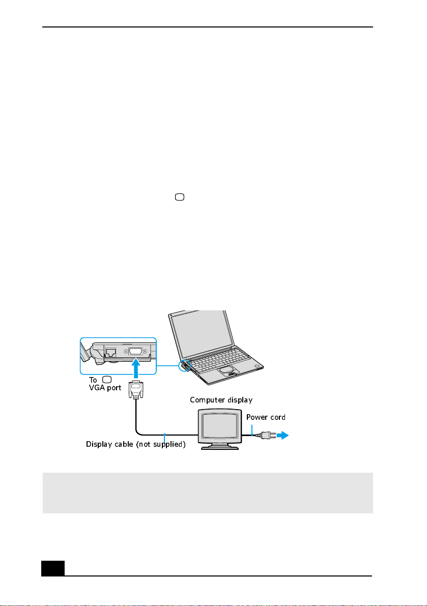
To connect a computer display
1 Turn off the computer before you connect the computer display.
2 Locate the VGA (Monitor) port.
3 Plug the display cable (no t supplied) into the VGA (Monitor) port.
4 Verify that the power cord is plugged into the computer display and an AC
outlet.
5 Turn on all external devices before turning on the computer.
Connecting an External Computer Display
To
VGA port
Computer display
Power cord
Display cable (not supplied)
✍ You cannot use the monit o r port on your computer when the docking station is
connected to the computer; however, you can use the monitor por t on the docking
station.
60
Page 61

Connecting an External Di splay
To connect a projector
1 Turn off the computer before you connect the projector.
2 Locate the VGA (Monitor) port and the Headphone jack.
3 Plug the display cable (not supplied) into the VGA port, and plug the
opposite end into the appropriate port on the projector.
4 Plug the audio cable (not supplied) into the Headphone jack, and plug the
opposite end into the appropriate port on the projector.
5 Verify that the power cord is plugged into the projector and an AC outlet.
6 Turn on all external devices before you turn on the computer.
Connecting a Projector
To Headphone jack
To VGA port
Audio cable
(not supplied)
Display cable
(not supplied)
Projector
Power cord
✍ See the manual that came with your projector for more information on its installation
and use.
61
Page 62

Change text in this var iable definition to docum ent title.
Changing the display when connecting an external computer
display or projector
When you connect an external display to the VGA (Monitor) port, you c an
toggle the output between the Liquid Crystal Display (LCD), the ext ernal
monitor, or both devices.
To chang e
Press the
Fn+F7 key combination to select a display. See “Select ing the Display
Mode” for more information.
To Press Result
Switch to an
external display
Fn+F7 Toggles between the LCD, the external display
connected to the Moni tor port, or both the LCD
and external display.
Only LCD
LCD and external display
Only external display
✍ Connect the extern al dis pl ay to t he no te book or port repl ic ator b ef ore you tur n on t he
unit, otherwise the Fn+F7 key combination will not work.
62
Page 63
Connecting wit h another VAI O computer
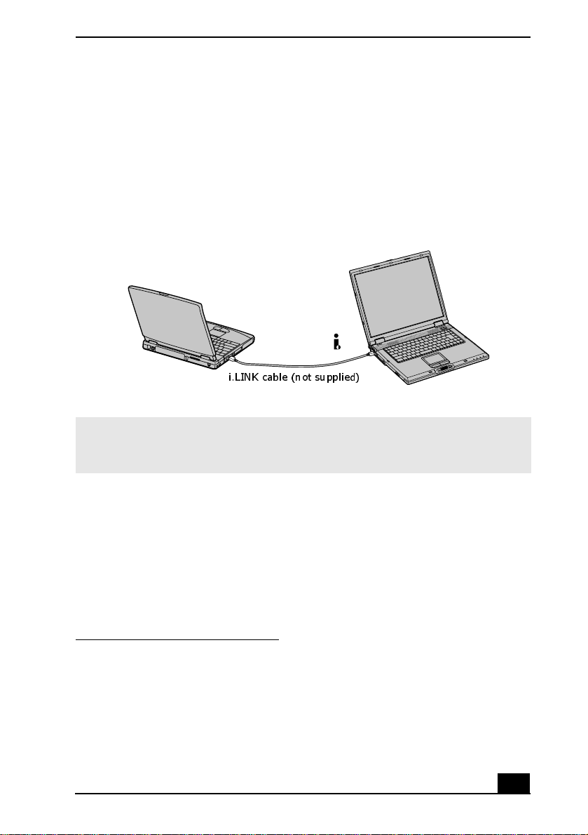
Connecting with another VAIO computer
Use an i.LI NK®* cable (not supp li ed) to c onnect your VAIO computer t o anothe r
computer that al so has an i. LINK port. You can use one computer to ed it, copy or
delete f iles on the other computer. Yo u can also print from a printer attached to
either computer.
Connecting with an i.LINK Cable
i.LINK cable (not supplied)
✍ When you connect two VAIO computer s, you must assign each computer a unique
name. You can identify the computers by this uni que name when the two computers
are networ ked together.
* i.LINK is a trademark of Sony used to designate that a product contains an IEEE 1394 con-
nection. The i.LINK connection may vary, depending on the software applications, operating
system, and compatible i.LINK devices. All products w ith an i.LINK connector may not
communicate wi th each other. Refer to the documentation that came with your compatible
i.LINK device for information on operating conditions and proper connection. Before connecting compatible i.LINK PC peripherals to your system, such as a CD-RW or hard disk
drive, conf irm their op e ra ting s yst em com p at ibility and required op er atin g con di tio ns.
63
Page 64
Change text in this var iable definition to docum ent title.
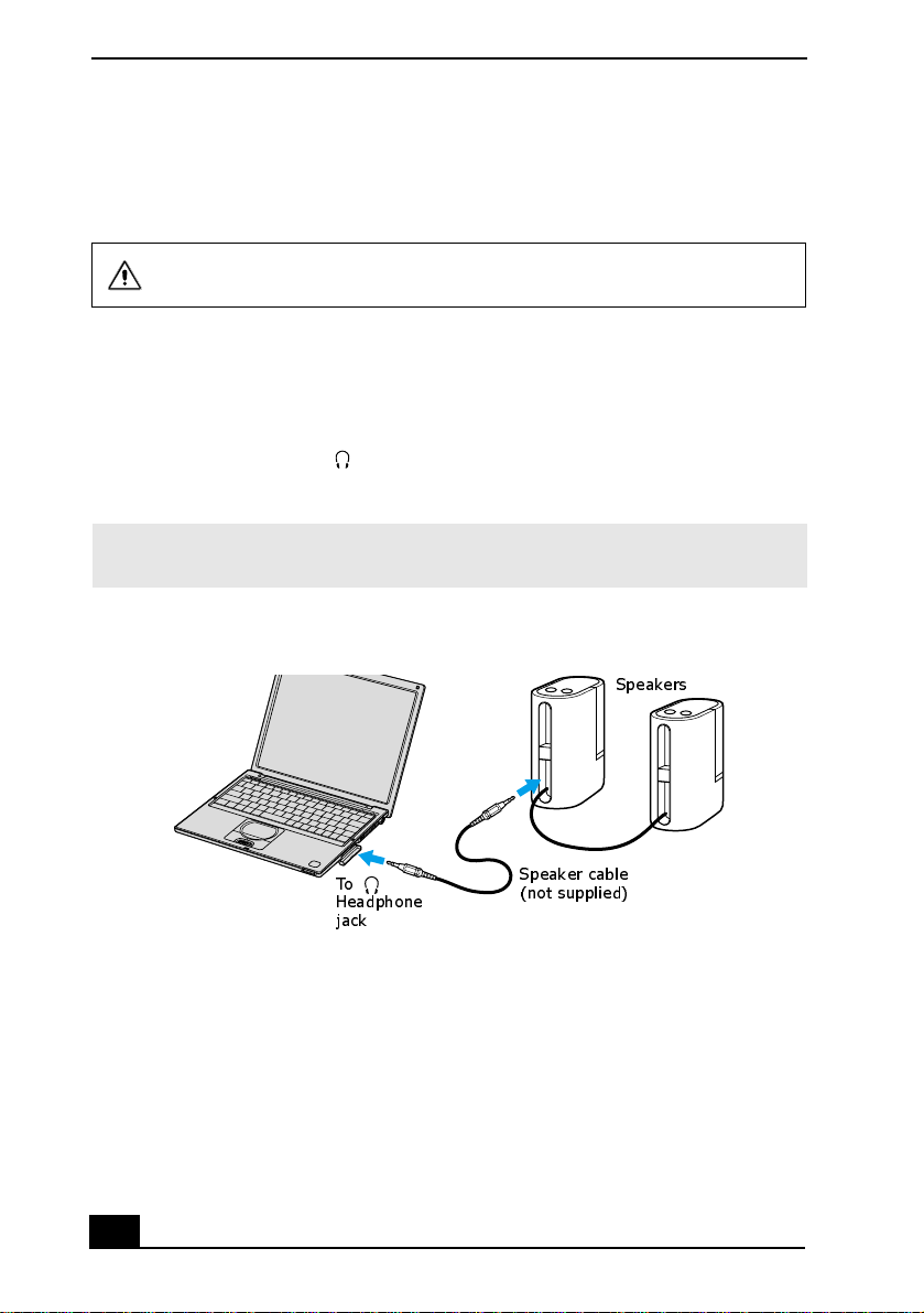
Connecting External Speakers
You can enhance the sound quality of your computer by connecting exte rnal
speakers (not supplied).
Do not place floppy disks on the speakers; the speakers’
magnetic field may damage the data on the floppy disks.
To connect external speakers
1 Verify that your speakers are designed for computer use.
2 Turn down the volume of the speake rs.
3 Locate the Headphone jack, and plug the speake r cable (not supp lie d) in to
this jack .
✍ See the manual that cam e with your speakers for more information on its installatio n
and use.
Connecting Speakers to the Headphone Jack
Speakers
64
To
Headphone
jack
Speaker cable
(not supplied)
Page 65

Connecting a Microph one
Connecting a Microphone
You can enhance the quality of sound input by using a microphone (not
supplied).
To connect a microphone
1 Verify that your microphone is designed for computer use and complia nt
with the plug-in power microphone. Do uble check
2 Locate the Microphone jack. A protruding dot above the Microphone
jack distinguishes this jack from the Headphone jack.
3 Plug the microphone cable (not supplied) into the Microphone jack.
✍ See the manual that came with your microphone for m ore information on its
installation an d use .
Connecting to a Microphone Jack
Microphone
(not supplied)
To
Microphone jack
To record from a microphone or audio equipment
You can record messages, memos, or other recordings in analog by connecting a
microphone or oth er audio equipment to the Microphone jack of your computer,
port replicator, or doc king station and swit ching the jack functionality. The
Microphone jack is for MIC IN (monaural).
1 Doub l e - c li ck the Volume icon on the taskbar. The Volume Control
window appears.
2 From the Options menu, click Properties. The Properties window appears.
65
Page 66

Change text in this var iable definition to docum ent title.
3 In the Adjust volume for box, click t he Recording opti on b utton t o s elec t it,
and then click OK. Th e Recording Control window appears.
4 If it is not already turned on, click the Select check box at the bottom of the
Microphone column. Close the Recording Control window.
5 Click Start on the taskbar, and select All Programs, Accessories,
Entertainment, and then Sound Recorder. The Sound - Sound Recorder
window appears.
✍ You are ready to begin recordin g. For help using Sound Recorde r, click Help in the
Sound Recorde r window.
Adjusting the volume
You can adjust the volume for playing or recording, but you can only adjust the
recording volume in the Recording Control window. If you adjust the volume,
the adjus tment is only e f fective for playing sou nd. I t does not adjust the volume
for recording sound.
To adjust the volume when playing
1 Double-click Volume icon in the taskbar. The Volume Control window
appears.
2 In the Volume Control colum n, mo ve the sli der up for i nc reased v olume and
down for decreased volume.
Sound device Function
Volume Control Adjust the sound level from the speakers or
headphones.
Wave Adjust the wavfile sound or the system sound of
Windows.
SW Synth
CD Audio Adjust the volum e of th e CD in the opti onal opti cal
drive.
66
Page 67

Connecting a Microph one
Sound device Function
Microphone Adjust the internal or external micr ophone volume.
Telephony Adjust the modem or telephone lin e volume.
PC Beep Adjust the beep sound when inserting or removing
the PC Card and other devices.
67
Page 68

Change text in this var iable definition to docum ent title.
Expanding Your Computer Capabilities
You can connect the follo wing peripheral d evices to your computer to expand its
capabilit ies and enhance its versatility to meet your needs:
❑ A Personal Digital Assistant (P DA)
❑ A Wireless LAN Access Point
❑ A Wireless LAN PC Card
Personal Digital Assistant
A handheld PDA is the quintessential personal planner and entertainment center
that fits in your pocket. With a PDA, you can easily perform the following
functions:
❑ Enter your schedul e details in the calendar and view them by the day, week,
or month, and even set an alarm to remind you of impo rtant even ts.
❑ Keep your contact na mes, addre sses, phon e numbe rs, and othe r detai ls in t he
address book and find t hem when you need them.
❑ Add tasks to the To Do List, prioritize them, and assign them due dates.
❑ Synchronize your dat a with the software on your computer to back up your
data.
❑ Track e xpenses when you are out of the office and transfer the data to your
notebook.
❑ Exchange data with your com puter.
Wireless LAN Access Point
The Wireless LAN Access Point is designed for building a wireles s Local Area
Network (LAN) environment. The Acces s Poi nt comes with the Wire less LAN
PC Card and required softwa re. You can easily bui ld a wire less LAN
environment by pluggi ng t he Acce ss Po int int o an AC power out le t, ins tal lin g the
Wireles s LAN PC Card in your computer, an d usi ng the provided software.
Because a wireless LAN configuration requires no wiring, you can operate
multiple computers more freely than ever before .
You can also connect your Access Point to a tel ephone line, Integra ted Services
Digital Network (ISDN) route r, cable modem, or Digital Subscribe r Line (xDSL)
modem to sh are access to the Internet amon g multipl e computers.
68
Page 69

Expanding Your Computer Capabilities
Wireless LAN PC Card
The W ir eless LAN PC Card, which comes with the Wireless LAN Access Point,
can be purchased separa tely and is designed for building a wireless LAN
environment. You can use the Wireless LAN PC Card with or without the ac cess
point. With th e ac ce s s bo i nt , y ou can build a wir e less LAN be t w ee n co mputers
that are equippe d wit h the W i reless LAN PC Card a nd gain a ccess to the In ternet .
Without the Access Point, you ca n achieve direct communic ation (Peer-to-Peer
mode) between computers.
✍ For more infor mation on S o n y Wireless LAN, go to
http://www.sonystyle.com/vaio/wirelesslan.shtml
69
Page 70

Change text in this var iable definition to docum ent title.
70
Page 71

Customizing Your VAIO
Computer
You can customize the settings of your computer. The following sections
briefly describe how to change your computer’s default settings. You can
also refe r to Sony Notebook Setup Help for more detailed information.
❑ Displaying the Sony Notebook Setup Screen
❑ Controlli ng P ower Management
❑ Displaying Battery Information
❑ Selecting the Display Mode
71
Page 72

Change text in this var iable definition to docum ent title.
Displ aying the Sony Notebook Setup Screen
✍ See the manual supplie d w ith your comp uter display for more inform ation on its
installa tion and use .
To display th e Sony Notebook Setup screen
1 From the Start menu, point to All Programs, and then Sony Notebook Setup .
2 From the Sony Notebook Setup menu, click Sony Notebook Setup.
Sony Notebook Setup Screen
3 Select the tab for the item you want to cha nge. See “Sony Notebook Setup
tabs” for more information.
4 After you finish making your change s, click OK.
72
Page 73

Displaying the Sony Notebook Setup Screen
Sony Notebook Setup tabs
Tab Description
About This Compute r Display system in form ation, including memory
capacity, serial number, and BIOS version.
Initial Setting Change the volume of the sounds that play while the
operating system is loading. Select the order of drives
and devices from which you want to load the operating
system. You can specify the hard drive as well as ot her
drives inserte d into your computer.
Touchpad Change touchpad settings, or enable/disable touchpad
functionality if you are using an external mouse.
Power On Password Set the password to secure your computer.
Bass Boost Set the Bass Boost option.
✍ For more information about each opti on, click Help on the Sony Notebook Setup
screen to display the Help file.
73
Page 74

Change text in this var iable definition to docum ent title.
Controlling Power Management
The PowerPanel™ utility enables you to co ntrol the power management of your
computer and provides key information about system activity and battery life.
The following sections briefly describe how to conserve your computer’s battery
power. You can also refer to PowerPanel Help for more information.
Viewing the Power Management status icons
The Power Management status icons are displayed on the taskbar. Move the
pointer over t he icons to s ee the tool ti p tha t dis plays info rmati on a bout the activ e
profile.
The current profile icon’s appearance changes depending on which powe r
management profile is currently sele cted. To change the power management
profile, right-click the current profile icon, and then select a profile from the popup list. See “Power Management profiles” for a desc ription of available
options.To select another power manage me nt command, click tha t icon in the
Power Management toolbar.
✍ When you use the battery pack to power your computer, your system selects the
Maximum Battery Life power management profile by def ault. If you s elect a
different power management profile while us ing battery pow er, that profile is
selected automatically the next time you use the battery pack to power your
computer.
Refer to PowerPane l H elp for informatio n on customizing the Power Management
settings.
You can chang e t he po wer man age ment se tt ing s, s uc h as t he sy st em ti me r an d the
brightness of the screen.
To access PowerPanel H el p
1 Click Start , point to All Programs, and se lect PowerPanel.
2 Click Help. The PowerPanel Help window appears.
74
Page 75

Controlling Power Management
To customiz e Power Management settings
1 Right-click the curre nt Profile icon on the taskbar.
2 Select Edit/Create Profiles from the menu. The Profile Editor window
appears.
3 Click a profile whose setting you want to change from the li st in the left
field.
4 Double-click an item whose se tting you want to change from the list in the
right field.
5 Click the desire d se tting.
6 Click the File menu, and then click Save.
7 Click the File menu, and then click Exit.
Power Management profiles
The PowerPanel ™ utility provides sev era l predefined power managemen t
profiles. Each profile consists of a group of power management settings that are
designed to meet specific power management goals — ranging from maximum
power management to no power management. You can change the settings for
any of the predefined profiles (except for the Disable Power Management
profile), or you ca n crea te your own profile to suit your portable computing
needs.
75
Page 76
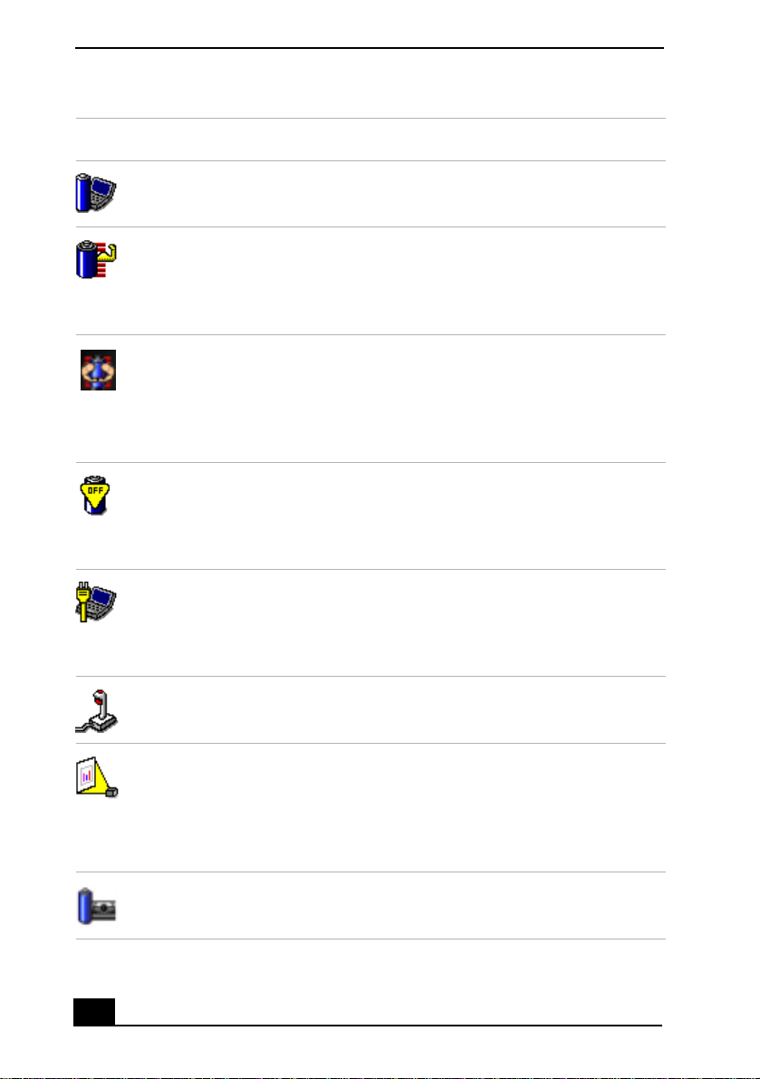
Change text in this var iable definition to docum ent title.
Icon Description
Maximum Performance
Provides the best system performance while still conserving power.
Maximum Battery Life
Provides power saving features to give you maximum battery life and
good performance. It slows the computer and puts it into Standby
mode after a specifi ed time period.
Ultimate Battery Life
Extends the Maximum Battery Life by disabling ports such as the
i.LINK port.
This profile dis ables many applicat ions such as Memory Stick,
DVgate, and Smart Capture.
Disable Power Management
Turns of f all power management features such as Standby and
Hibernate modes.
You can not change the settings of th is profile.
76
AC Power
The power management state when AC power is in use. Similar to the
Power Management Off setting. Power Management automatically
loads the AC profil e unless you disable th is feature.
Games
Disables the display and the Hard Disk Standby timer.
Presentation
Keeps the dis p lay on at all times while it conserves po wer. This option
is ideal for slide show presentations. You can establis h se ttings for
LCD (Video) Standby, Hard Disk Standby, and Standby to optimize
power management for your system.
Camera
Optimizes performance and power requirements for camera usage.
Page 77
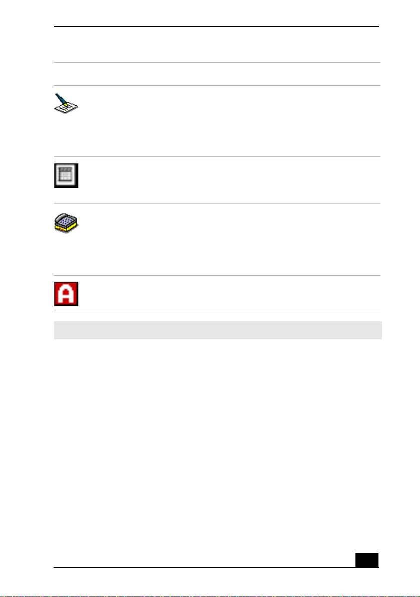
Icon Description
Word Processing
Optimizes power management with longer time outs on the hard disk
and display screen . You can also establish s ettings for LCD (Video)
Standby, Hard Disk Standby, and Standby to optimize power
management for your syst em.
Spreadsheet
Optimizes performance and power require ments for spreadsheet
applications.
Communications
Extends battery life by initia ting a quick display timeout. The Intern al
modem remains powered. You can also establish settings for LCD
(Video) Standby, Hard Disk Standby, and Stand by to optimize power
management for your syst em.
Automatic Profile Selection
Automatically switches to a profile suitable f or active app lications.
Controlling Power Management
✍ Do not choose the Automatic Profil e Selection when connected to AC power.
Power Management commands
PowerPanel™ also provides power management commands that you can use to
activate s pecifi c power manage ment fu nction s and t o control power for a specifi c
device. You can use these commands to override a profile setting or initiate an
immediate action.
77
Page 78

Change text in this var iable definition to docum ent title.
Icon Description
Standby
Puts the system into Standby mode, a power management state that
saves the state of the system and peripheral device s in memory
(RAM). Power consumptio n r educ es to a minimum, and the system
remains on. To return the system to the active state, pr ess any key or
the power button on your computer.
Hibernate
Provides for the lowe st level of power consumption. The system
writes the state of the system and peripheral devices to the hard disk
drive and turns off the system power. To return th e system to the
original state, use the power button to turn on power. The system
saves the data in the Save to Disk Partition on the hard disk drive.
LCD (Video) Standby
Turns off the video displ ay to save power . If you turn off the Video
Standby ti mer, the dis play remains active except when the syste m
enters Sta ndby mode. The video displ ay s ystem is one of the lar g est
consumers of power in the system.
Conserving battery power
When using the computer with a ba ttery, the LCD display a nd the hard disk drive
can be set to switch off automatica lly to conserve battery power .
See “Power Management profiles” for more information.
78
Page 79

Displaying Batter y Information
Displaying Battery Information
[[Can’t confirm yet]]
You can display information for the battery on your computer. The following
sections brie fly describe how to displa y your com puter’s general battery
information. You can also refer to PowerPanel Help for more detailed
information.
To display the Battery Information window
1 Double-clic k th e cur rent P rofil e ico n on the ta skba r. The Battery In fo rmati on
window appears.
2 For additional inform ation, click the Help butt on. The PowerPanel Help
window appears.
To display the Battery Information toolbar
1 Right-click the taskbar, point to Toolbars, and select Battery Information.
2 The Battery Information toolbar appears on the taskbar.
The toolbar displays battery stat us gauges and the battery status icon.
Battery Information Toolbar
❑ Percentage indicator — Displays the percentage of the remaining capacity.
❑ Time in dicator — Displays estimated time (hours:minutes) remaining
before the battery fully dra ins, also referred to as the time-to-empty.
To close the Battery Information toolbar
1 Right-click the Battery Information toolbar, and point to Toolbars.
2 Click to deselect Battery Information. The toolbar disappears from view.
79
Page 80

Change text in this var iable definition to docum ent title.
Battery icon descriptions
Battery ic on Battery status
Charging
Fully ch arged
Discharging
No battery
Displaying detailed battery information
Double-clic k the battery icon on the task tray to display the Ba ttery Information
window. The screen appea r s displaying the Battery tab, which contains
information such as the estimated time-to-empty and char ging time.
80
Page 81

Battery Information Window
Displaying Batter y Information
Customizin g th e Battery Informat ion toolbar and alarm system
You can customize the Battery Information toolbar to suit your portable
computing needs , including modifications to the alarm settings. Refer to
PowerPanel Help for more information.
Changing the window design of Sony software
To change the window design
1 Click the Sta r t button, then select Control Pa nel.
2 In the left window pane of Control Panel, click “Switch to Classic View.”
3 Double-click UI Design Selector.
4 Click << or >> and select th e desired design.
81
Page 82

Change text in this var iable definition to docum ent title.
5 Click Apply. The “UI Design Selector” window design change s. The
window design for your Sony software will match the “UI Design Selector”
window.
6 To try another selection, click << or >> and then click OK to close the UI
Design Selector.
✍ This feature is available with UI Des ign Selector-compatible softwa re only.
82
Page 83

Selecting the Displ ay M ode
Selecting the Display Mode
[[Can’t confirm steps yet]]
This compu ter uses the Intel® vide o controller, which enables you to select the
desired display when the computer is connected to an external monitor. When
you connect an external display, you can switch the display mode between your
notebook’s LCD display and the external monitor.
To select the dis p la y mode
1 Click Start, and point to Control Panel.
2 Click Display. The Display Properties window ap pears.
3 From the Settings tab, click Advanced, and select the Intel® Graphics
Technology tab to display the Intel® 82815 Graphics Controller Pro perties
dialog box.
83
Page 84

Change text in this var iable definition to docum ent title.
Intel® 82815 Graphics Controller Properties Screen
4 Click the Inte l® Gra phics Technology tab, t hen clic k t he Graph ics Proper ties
button.
5 Click the Device tab.
6 Select the type of display.
✍ You may not be able to disp lay the computer LCD screen and an external display or
projector at the same ti m e, depending on the types of com puter displa ys and
projectors you are using.
Turn on the computer after you turn on the peripheral devices.
84
Page 85

Adding Memory
In the future you may want to install memory modules to expand the
functionality of your computer. See the Specifications flyer supplied with
your computer for the amount of memory preinstalled on your computer.
Expansion memory modules are available as options. For memory
upgrades, use only unbuffered PC100 (CL2) SDRAM µDIMM modules.
(Sony offers the optional 128 MB PCGA-MM128T memory module.)
This section provides you with information on removing and replacing a
memory module:
❑ Precautions and Procedures
❑ Removing a Memory Module
❑ Installi ng a Memory Module
❑ Confirming Added Memory Capacity
85
Page 86

Change text in this var iable definition to docum ent title.
Precautions and Procedures
The procedures describe d below ass ume familia rit y with the genera l term inology
associated with personal computers and with the safety practices and regulatory
compliance req uired for using and modifying ele ctronic equipment.
Sony reco m me nds that memory upgr ades be performed by an authorized
Sony Service Center. To find the nearest center or agent, go to:
http://www.sony.com/pcsupport.
Be caref ul when i nstal li ng a memory m odule in you r comput er, and be sure
to observe the proper safety precautions listed below. Mistakes that occur
when install ing or removing a memory module may cause a ma lfunction.
❑ Disconnect the sys tem from its power source and from any
telecommunications links, networks, or modems before you open the system
or follow any of the procedures desc ribed below. Failure to do so may result
in personal injury or equipment damage.
❑ Electrosta tic d ischa r ge (E SD) c an damag e dis k drives a nd o ther c ompone nts.
Perform the procedure s descr ibed below only at an ESD worksta tion. If such
a station is not av ailable, do not work in a carpeted area, and do not handle
materials that produce or hold static electri city (cellophane wrappers, for
example). Ground yours elf by maintaining contact with an unpainted metal
portion of the chassis while performing the procedure.
❑ Do not open the memory module package until you are ready to install the
module. The package protects the module from ESD.
❑ Use the special protective package to s t ore a memory module and pr event
ESD, or wrap the memory module in aluminum foil.
Typical expansion memory configuration
Total System Memory (MB) On board (MB) Slot (MB)
128 128 0
256 128 128
86
Page 87

Installing a Memo ry Module
Installing a Memory Module
To add a memory module, proceed as follows:
1 Turn off the computer and all peripheral devices.
2 Disconnect the power cord and all c ables from the comput er, and remove the
battery.
3 Wait for the computer to cool down.
✍ The interior of the computer becomes extremely hot during operation. Wait at least
one hour for the computer to cool down before you rem ove the screws.
4 Use an appropriate screwdriver to loosen and remove the thre e screws at the
bottom of the computer.
To avoid damaging the computer, do not remove or loosen any other sc rews.
Removing Bottom Screws
Screws
5 Slide the LCD lock lever and lift the cover.
6 Slide the keyboard towa rd the LCD display, then lift it away slightly.
87
Page 88

Change text in this var iable definition to docum ent title.
Lifting the Keyboard
7 Lift the keyboard from the LCD display side.
8 Gently turn the keyboard over the touchpad. Take care not to detach the
cable when lifting the keyboard.
9 Touch a metal object (such as the connector panel on the back of your
computer) to discharge static electricity.
10 Remove the existing memory module.
11 Remove the new memory module fr om it s packaging.
12 Install the memory module by sliding the module into the open slot.
Do not touch any part of the motherboard or the other com p onents inside
the computer.
88
Page 89

Installing a Memo ry Module
Installing New Memory Module
13 Snap the connectors into plac e when the board is correctly seated.
14 Close the comp u ter cover and replace the three (3) fastening s cr ews on the
bottom of the computer.
89
Page 90

Double
check
grfx???
Change text in this var iable definition to docum ent title.
Removing a Memory Module
1 Turn off the computer and all pe ripheral devices.
2 Disconnect the power cord a nd all c abl es from the com puter, and remove the
battery.
3 Wait for the computer to cool down.
✍ The interior of the computer becomes extremely hot during operation. Wait at least
one hour for the compute r to cool down before you remove the screws.
4 Use an appropriate sc rewdriver to loosen and remove the thre e screws at the
bottom of the compute r.
To avoid damaging the com puter, do not remove o r loosen any other screws.
Removing Bottom Screws
Screws
5 Slide the LCD lock lever and lift the cover.
6 Slide the keyboard toward the LCD display, then lift it away slightly.
90
Page 91

Removing a Memory Module
Lifting the Keyboard
???
7 Lift the keyboard from the LCD display side.
8 Gently turn the keyboard over the touchpad. Take care not to detach the
cable when lifting the keyboard.
9 Touch a metal object (such as the connector panel on the back of your
computer) to discharge static electricity.
10 Remove the memory module by pulling out the tabs (se e a rrows No. 1), and
pulling out the module in the direction of arrow No. 2.
Removing a Memory Module
11 Gently replace the keyboard, then press it into your computer.
12 Close the comp u ter cover and replace the three (3) fastening s cr ews on the
bottom of the computer.
91
Page 92
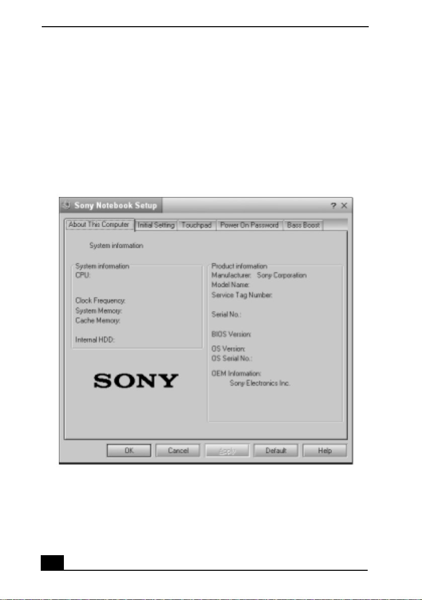
Change text in this var iable definition to docum ent title.
Confirming Added Memory Capacity
1 Turn on the computer.
2 Click Start on the Windows® taskbar, point to All Programs, and then click
Sony Notebook Setup.
3 Click the About This Notebook tab. Verify that the System Memory
displayed in the le ft panel matches the amo unt of memory installed.
Sony Notebook Setup Dialog Box
92
Page 93

About the Soft ware on Your
Computer
Your VAIO® computer is ready to help you work, play, learn, and
communicate as soon as you turn it on. This section gives you the
following:
❑ Software Overview
❑ DVgate application notes
❑ Software Support Information
Software Overview
Your computer may not be supplied with all of the software liste d below,
depending on the configuration you purchased. Preinstalled software may not be
identical to retail versions, or include supporting documen tation.
Your computer may not be supplied with all of the software liste d below,
depending on the configuration you purchased. Preinstalled software may not be
identical to retail versions or include supporting documentation.
Adobe® Acrobat® Reader ®
Adobe Systems Inc.
Acrobat Reader soft ware allows you to view, navigate, and print electronic
documents in Adobe’s Portable Document Format (PDF), an open file format
that is intended to preserve the fidelity of documents created on all major
computer platforms.
Adobe® Photoshop® Elements (On selected models)
Adobe Systems Inc.
Using state-of-the-art im age editing tools, you can unleash your artistic ability
and create digital imag es for print, e-mail and posti ng to the Web. The versatile
image capturing options allow you to start working with digital and traditional
photos immediately. Explore endless creative possibilities for your personal
images with Adobe Photos hop El ements software.
93
Page 94

Change text in this var iable definition to docum ent title.
America Online®
America Online, Inc.
America Online is a popular Internet online service. Stay in touch with family
and friends wit h ea sy-to-u se e -mail . Mana ge you r pe rsona l fina nces , get the la test
news and sports scores , and chat with thousands of others who share your
interests.
DigitalPrint
Sony Electronics Inc.
This image management software makes it fun and easy to edit, import, and
organize your digital pictures in a photo album for rich digital printing to any
standard color la se r or ink-jet printer. DigitalPrint can also be used to make
custom CD labels for your audio CDs.
DVgate™
Sony Electronics Inc.
Connect a digital video camera recorder to the i.LI NK® port and capture your
own video clips and st ill images. You can edit clips from your video, add new
clips, and comb ine clips into new movie segments. You can also save your
images in a variety of popu lar file formats.
EarthLink Total Access®
EarthLink, Inc.
An Internet Servic e Provider that supplie s acce ss, information, and ass istance to
its customers, introducing them to the Internet. Member benefits include e-m ail,
newsgroups, a P ersonal Start Page, free storag e space for your personal Web site,
a member magazine, and 24-hour technical support.
EverQuest (On selected models)
Sony Online Entert ainment Inc.
This introduc tory edition of EverQuest, a living, constantly evolving fantasy
world, takes users to new heights of online role-playing gaming.
Jog Dial Utility
Sony Electronics Inc.
The Jog Dial Utility enables you to easi ly scroll, launch applications, acce ss
settings, and perform other useful functions by manipulating the center Jog
Dial™ control, which is located near the touchpad.
94
Page 95

About the Softw are on Your Computer
Microsoft® Office XP Professional (On select ed mode ls)
Microsoft Corp.
Microsoft Office XP software redefine s t he rel ationship between people and
software by providing a smarter, simpler way of working. New Office XP
software feature s include context-sensitive smart tags, enhanced formatting
options, and more, that enable you to continually integrate additional services
into Office and access information anytime.
Microsoft® Office XP Small Business Edition (On selected models)
Microsoft Corp.
With Micr osoft Offic e XP sys tem you’l l find a powerful new technology tha t will
help you get work done more quic kly by providing real- tim e, context-sensi tive
options for important actions, from formatting to error correction. Task panes
consolida te import ant task s int o a si ngle in te grated view, enabling you to co nduc t
searches, launch and format documents, and view the contents of your Clipboard
from one location.
Microsoft® Word (On selected models)
Microsoft Corp.
Microsoft Word makes it easy to create com mon Web, e-mail, and print
documents for us e ar o u nd th e wo r ld . I t em br a ces HTML as a f ir st - cl as s fi le
format and ext ends Word's ease-of-use to the Web and e-mail. Word also extends
that ease-of-use to international users, making it easy to create multil ingual
documents.
MovieShaker™ (On selected models)
Sony Electronics Inc.
Sony’s original MovieS hake r software creates perso nal movies that have
transiti ons, backg round m usic, an d text. Just import you r video cl ips and “shake”
with a click of the mouse. Your personal movies are easy to create and fun to
share with family and friends.
PC-Cillin® 2000
Trend Micro, Inc.
PC-Cillin software provi des portable, easy-to-use, real-time antivirus security at
your computer’s entry point (beaming, synchronization, Internet access) to
defend against potential threa ts hidden inside fil es, e-mail, or on the Web.
95
Page 96

Change text in this var iable definition to docum ent title.
PicoPlayer™
Sony Electronics Inc.
PicoPlayer software is a video player utility that enables you to use Giga
Pocket™ Personal Video Recorder functions on a computer that does not have
Giga Pocket Personal Video Recorder installed. You can play Video Capsules
created by Giga Pocket Personal Video Recorde r, and, if a Giga Pocket Server is
available on your home network, watch TV streamed from the Giga Pocket
Server and remotely control the Giga Pocket Server’s TV programming
functions.
Quicken® 2002 New User Edition
Intuit Inc.
Quicken software is the fastest, easies t way to organize your finances. Quicken
software works just like your checkbook, so it' s e asy to learn and use. You can
even pay your bills online. Quicken software manages all of your finances, bank
accounts, credit cards, investments, and loans. (Users of other versions of
Quicken must upgrade for a fee.)
QuickTime®
Apple Computer, Inc.
The versatile QuickTime softwa re plays hundreds of diff erent kinds of files,
including vide o, audi o, and virtua l real ity (VR) m ovies . You can play QuickT ime
files (referred to as “QuickT im e m ovies”) using QuickTime Player or any other
application, such as a Web browser or word processor, that supports QuickTime
software
RealPlayer®
RealNetworks, Inc.
RealPlayer software is a high-quality streaming media player that supports many
digital media formats. The user-friendly interface has enhanced navigation
capabilit ies, allowing you to access and enjoy audio and video programming over
the Internet. RealPla yer software is your gat eway to a superb Interne t multimedia
experience.
96
Page 97

About the Softw are on Your Computer
Smart Capture
Sony Electronics Inc.
Smart Capture is a fun new way to send multimedia message s vi a e-mail. Smart
Capture manages the i.LINK® connection between your notebook and a Sony
Digital Handy ca m® Camcorder that supports the i.LINK int erface. It allows you
to capture comp ressed video or s till images and save t hem t o your hard di sk dri ve
or share via e-mai l. A smart solution for computer, digital audio/video and
network convergence.
SonicStage™
Sony Electronics Inc.
This new juke box application adds a host of new features to its predecessor,
OpenMG™ Jukebox. Continuing to take advantage of Sony’s copyright-
protected ATRAC3™ format for high-quality digital audio storage, SonicStage
software sports a new music visuali zer, a sleek new player skin design, audi o CD
burning capabi lity, and a parametric equalizer for fine-tuning audio playback.
Sony ScreenBlast™ ACID (On selected models)
Sony Pictures Digital Enter tainment
With the powerful Sony ScreenBlast ACID software you can create royalty-free
music by utilizing its loop-based production tool, including unlimited tracks and
enhanced effe cts.
Sony ScreenBlast™ Sound Forge (On selected models)
Sony Pictures Digital Enter tainment
Sony ScreenBlast Sound Forge allows you to record, edit, and process mono or
stereo audio files for your multimedia or Internet projects. Whether you want to
use a number of professional effects, convert video into streaming media, or
synchroniz e audi o to video — this software has everyth ing you need to create
rich, imme r sive multime dia and Internet content.
Sony on Y ahoo!
Yahoo! Inc.
Personalize your own web portal with Sony on Yahoo! Get a free webmail
account, customized news and local weather reports, comics, instant messaging,
and more.
97
Page 98

Change text in this var iable definition to docum ent title.
VAIO Action Setup
Sony Electronics Inc.
VAIO Action Setup manages the settings for your computer 's S hortcut keys.
VAIO Support Agent (On selected models)
Sony Electronics Inc.
VAIO Support Agent provides imme diate, interac tive, online support with
information about your preinstalle d so ftware and answers to frequently asked
questions.
WinDVD® 2000
InterVideo, Inc.
WinDVD 20 00 software is a simp le-to-u se DVD p layer tha t of fers a ll t he fea tures
you would expect to find in a standard consumer DVD player, while also
including advanced display and navigation features such as zoom, pan,
bookmark, and time search.
98
Page 99

DVgate application notes
DVgate application notes
Digital video captures
If your system displays the messag e, “Failed to record to DV deck, please check
deck’s power status, cable connection…,” while you are r ecordin g images to a
digital video device using DVgate software, close all open applications, and
restart your compu ter. Frequent recording of im age s to a digital video dev ice
while using DVgate may caus e th is situation to occur.
For more information on DVgate software, see the DVgate onl ine help .
Adjusting image resolution
If the images on the LCD do not display smoothly, the resolution may not be set
correc tl y. To check the reso lu t io n , cl i ck th e Setup butt on in th e DV g at e
Motion-Monit or window. Point to Settings, and then select Low Resolution. The
settings you cha nge in this menu aff ect the images in the monit or window only.
Movie data importe d to your hard drive and images recorded to DV devices will
not be affected.
Hard disk drive partition
In order to improve the performance of your computer’s DVgate™ motion
software, the har d dis k dr ive on your computer has been formatted with two
partitions , C and D. The C partition hold 40 percent and the D partition holds 60
percent of the en tire drive capacity. DVgate sof tware saves files to th e D
partition. This prevents large video capture from consuming the available space
on your C partition. To maintain optimum performance of DVgate, you should
defragment or format the D partition regularly.
To defragment a partition
Before you begin to defragment a partition, make sure you back up all
files that you want to save.
❑ Click the Start button in the Windows® taskbar.
❑ Click Progra ms, Accessories, System Tools, and then click Disk
Defragmenter. The Disk Defragmenter window appears.
99
Page 100

Change text in this var iable definition to docum ent title.
Select the drive you want to defragment from the list, and click the Defragment
button. See Windows® Help for more information on defragme nting.
100
 Loading...