

Page 1

DIGIT AL AUDIO MIXING CONSOLE
OXF-R3
OPERA TION MANUAL
1st Edition (Revised 3)
Software Version 3.0 and Later
[English]
Page 2

CAUTION
Installation has to be done by a SONY authorized
technician.
WARNING
To prevent fire or shock hazard, do not expose the unit to
rain or moisture.
To avoid electrical shock, do not open the cabinet. Refer
servicing to qualified personnel only.
VORSICHT
Um Feuergefahr und die Gefahr eines elektrischen Schlages
zu vermeiden, darf das Gerät weder Regen noch
Feuchtigkeit ausgesetzt werden.
Um einen elektrischen Schlag zu vermeiden, darf das
Gehäuse nicht geöffnet werden. Überlassen Sie
Wartungsarbeiten stets nur einem Fachmann.
For customers in the U.S.A
WARNING
This equipment has been tested and found to comply with
the limits for a Class A digital device, pursuant to Part 15 of
the FCC Rules. These limits are designed to provide
reasonable protection against harmful interference when the
equipment is operated in a commercial environment. This
equipment generates, uses, and can radiate radio frequency
energy and, if not installed and used in accordance with the
instruction manual, may cause harmful interference to radio
communications. Operation of this equipment in a
residential area is likely to cause harmful interference in
which case the user will be required to correct the
interference at his own expense.
You are cautioned that any changes or modifications not
expressly approved in this manual could void your authority
to operate this equipment.
For customers in Europe
This product with CE marking complies with both the EMC
Directive (89/336/EEC) and the Low Voltage Directive
(73/23/EEC) issued by the Commission of the European
Community.
Compliance with these directives implies conformity to the
following European standards:
• EN60950 : Product Safety
• EN55103-1: Electromagnetic Interference (Emission)
• EN55103-2: Electromagnetic Susceptibility (Imunity)
This product is intended for use in the following
Electromagnetic Environment(s)
E4 (controlled EMC environment, ex. TV studio)
Pour les clients européens
Ce produit portant la marque CE est conforme à la fois à la
Directive sur la compatibilité électromagnétique (EMC)
(89/336/CEE) et à la Directive sur les basses tensions
(73/23/CEE) émises par la Commission de la Communauté
européenne.
La conformité à cas directives implique la conformtié aux
normes eropéennes suivantes:
• EN60950 : Sécurité des produits
• EN55103-1 : Interférence électromagnétiques (émission)
• EN55103-2 : Sensibilité électromagnétique (immunité)
Ce produit est prévu pour étre utilisé dans les environments
électromagnétiques suivants:
E4 (environment EMC contrôlé ex. studio de télévision).
Für Kunden in Europa
Dieses Product besitzt die CE-Kennzeichnung und erfüllt
sowahl die EMV-Directive (89/336/EEC) als auch die
Directive Niederspannung (73/23/CEE) der EGKommission.
The shielded interface cable recommended in this manual
must be used with this equipment in order to comply with
the limits for a digital device pursuant to Subpart B of Part
15 of FCC rules.
!
This symbol is intended to alert the user to the
presence of important operating and maintenance (servicing)
instructions in the literature accompanying the appliance.
Die Erfüllung dieser Directiven bedeutet Konformität für die
folgenden Europäischen Normen:
• EN60950 : Produktsicherheit
• EN55103-1 : Electromagnetische Interferenz (Emission)
• EN55103-2 : Electromagnetische Empfindlichkeit
(Immunität)
Dies Produkt ist für den Einsatz unter folgenden
electromagnetischen Bedingungen ausgelegt:
E4 (kontrollierter EMV-Bereich, z.B. Fernsehstudio)
Page 3

Peak Inrush Current
OXF-CP3048PS
(1) Power ON, current probe method:
50A (100V)
110A (240V)
(2) Hot switching inrush current, measured in
accordance with European standard EN55103-1:
40A (230V)
OXF-IO3000
(1) Mise sous tension (ON), méthode de sondage du
courant:
20A (100)
70A (240V)
(2) Mesuré conformément
EN55103-1:
à la norme européenne
30A (230V)
OXF-SP3000
(1) Power ON, current probe method:
40A (100V)
80A (240V)
(2) Hot switching inrush current, measured in
accordance with European standard EN55103-1:
80A (230V)
OXF-IO3000
(1) Power ON, current probe method:
20A (100V)
70A (240V)
(2) Hot switching inrush current, measured in
accordance with European standard EN55103-1:
30A (230V)
Appel de Courant de Crête
OXF-CP3048PS
(1) Mise sous tension (ON), méthode de sondage du
courant:
50A (100V)
110A (240V)
(2) Mesuré conformément
EN55103-1:
40A (230V)
à la norme européenne
Spitzenstrom
OXF-CP3048PS
(1) Einschaltstrom, Stromsonde:
50A (100V)
110A (240V)
(2) Gemessen in EN55103-1:
40A (230V)
OXF-SP3000
(1) Einschaltstrom, Stromsonde:
40A (100V)
80A (240V)
(2) Gemessen in EN55103-1:
80A (230V)
OXF-IO3000
(1) Einschaltstrom, Stromsonde:
20A (100V)
70A (240V)
(2) Gemessen in EN55103-1:
30A (230V)
OXF-SP3000
(1) Mise sous tension (ON), méthode de sondage du
courant:
40A (100V)
80A (240V)
(2) Mesuré conformément
EN55103-1:
à la norme européenne
80A (230V)
i
Page 4

OXF-CP3048PS only
WARNING
This unit has no power switch.
When installing the unit, incorporate a readily
accessible disconnect device in the fixed wiring, or
connect the power cord to a socket-outlet which must
be provided near the unit and easily accessible.
If a fault should occur during operation of the unit,
operate the disconnect device to switch the power
supply off, or disconnect the power cord.
WARNUNG
Dieses Gerät hat keinen Netzschalter.
Beim Einbau des Geräts ist daher im Festkabel ein
leicht zugänglicher Unterbrecher einzufügen, oder das
Netzkabel muß mit einer in der Nähe des Geräts
befindlichen, leicht zugänglichen Wandsteckdose
verbunden werden.
Wenn während des Betriebs eine Funktionsstörung
auftritt, ist der Unterbrecher zu betätigen bzw, das
Netzkabel abzuziehen, damit die Stromversorgung
zum Gerät unterbrochen wird.
WARNING: THIS WARNING IS APPLICABLE FOR
USA ONLY.
If used in USA, use the UL LISTED power cord
specified below.
DO NOT USE ANY OTHER POWER CORD.
Plug Cap Parallel blade with ground pin
(NEMA 5-15P Configuration)
Cord Type SJT, three 16 or 18 AWG wires
Length Less than 2.5 m (8 ft 3 in)
Rating Minimum 10 A, 125 V
Using this unit at a voltage other than 120V may
require the use of a different line cord or attachment
plug, or both.
To reduce the risk of fire or electric shock, refer
servicing to qualified service personnel.
ii
Page 5

Table of Contents
About This Manual....................................................................................5
Chapter 1
Overview
Chapter 2
Powering The OXF-R3
Chapter 3
Getting Started
1-1 Overview......................................................................................... 1-2
1-2 Data Flow........................................................................................ 1-4
1-3 Signal Flow...................................................................................... 1-6
2-1 OXF-R3 Start-Up........................................................................... 2-2
2-1-1 Start-Up Procedure............................................................. 2-2
2-2 OXF-R3 Shutdown......................................................................... 2-4
2-2-1 Shutdown Procedure .......................................................... 2-4
3-1 The Control Surface...................................................................... 3-2
3-2 Fader Paging.......................................................................... 3 - 8
3-3 Assignable Channel Processing................................. 3 - 9
3-4 Input Channel, Equaliser and Filters.............. 3-10
3-5 Free Assign Area and Dynamics............................... 3-11
3-6 Multitrack, Routing for Multitrack,
Super Send Groups and Multi-Format.................... 3-12
3-7Sends......................................................................................... 3-13
3-8 Select To Faders.............................................................. 3-14
3-9 Select To Pans................................................................... 3-17
3-10 Basic Console Operations........................................3-18
3-10-1 To Route a Mic or Line Input to the Main Output Bus ... 3-19
3-10-2 To Set Up a Super Send Group from Channel Inputs...... 3-20
3-10-3 To Send Signals to Tracks on Tape ................................. 3-21
3-10-4 To Monitor Signals to and from Tape.............................. 3-22
3-10-5 To Set Up a Stereo Headphone Mix for Foldback 1 O/P 3-23
3-10-6 To Equalise Signal Feeding the Multitrack ..................... 3-24
3-10-7 To Equalise Monitor Signal Post Multitrack ................... 3-25
3-10-8 To Insert Dynamics Pre Multitrack Send......................... 3-26
3-10-9 To Insert Dynamics Post Multitrack Return .................... 3-27
3-10-10To Bounce Tracks ............................................................ 3-28
3-10-11To Set Up Super Send Groups from Multitrack .............. 3-29
3-10-12To Set Up a De-Esser Using Dynamics Side-Chain EQ.. 3-30
3-10-13To Link Compressor Side-Chains in a Group ................. 3-31
3-10-14To Link Compressor Side-Chains so that One Channel
Controls a Second Channel.............................................. 3-32
Table of Contents 1
Page 6

Table of Contents
Chapter 4
Signal Paths
4-1 The Basic (Default) Signal Path................................................... 4-2
4-2 Stereo Mix-Down Signal Path with Processing Inserted........... 4-4
4-3 Mix-Down with Post Channel Fader Insert................................ 4-6
4-4 Recording to a Multitrack............................................................ 4-7
4-5 In-Line Channel Multitrack Recording Set-up.......................... 4-8
4-6 In-Line Channel with Insert Post Channel Fader
(Monitor Function)........................................................................ 4-9
4-7 SEND 1 Pre Fader Headphones Feed........................................ 4-10
4-8 SEND 1 Post Fader Headphones Feed...................................... 4-11
4-9 Broadcast Mode........................................................................... 4-12
4-10 Channel Metering........................................................................ 4-15
4-10-1 Channel Meter Default..................................................... 4-15
4-10-2 Channel Meters to Input .................................................. 4-15
4-10-3 Send Monitor ................................................................... 4-16
4-10-4 Return Monitor ................................................................ 4-16
4-10-5 MULTI in Channel Path .................................................. 4-17
4-11 Dynamics Side-Chain Linking................................................... 4-18
4-11-1 Dynamics Side-Chain Link Right .................................... 4-18
4-11-2 Dynamics Side-Chain Busses 1-4 .................................... 4-20
4-12Mixing to the Main Output Bus.............................. 4-22
4-12-1 Main Output Bus Set-up .................................................. 4-24
4-12-2 Channel Signal to the Main Output ................................. 4-26
4-13 Multi-Stem Set-up........................................................ 4-29
4-13-1 Multi-Stem Set-up Procedure .......................................... 4-32
4-13-2 Multi-Stem Monitor Path ................................................. 4-36
4-13-3 Multi-Stem Source Channels ........................................... 4-40
4-13-4 STEM Monitor Switching ............................................... 4-48
4-13-5 STEM Monitor Switching GUI Set-up ............................ 4-50
4-13-6 Fold-Down Matrix GUIs ................................................. 4-52
Chapter 5
Control Screens
Chapter 6
Technical Descriptions
5-1 The Master Control Screens.......................................................... 5-2
5- 2Channel Screens.................................................................... 5 - 5
5-2-1 Routing GUI........................................................................... 5-8
5-2-2 I/O GUI ................................................................................ 5-11
5-2-3 Equaliser & Filters GUI ....................................................... 5-28
5-2-4 Dynamics GUI ..................................................................... 5-29
5-2-5 Preferences GUI ................................................................... 5-30
5-2-6 Master GUI (Includes Main Bus Outputs) ........................... 5-39
6- 1OXF-R3 System Description............................................ 6 - 2
6-1-1 Control Surface Configurations ........................................... 6-3
6-2 Channels Section Panels................................................................ 6-6
6-2-1 Fader Panel........................................................................... 6-6
6-2-2 Select to Faders Panel .......................................................... 6-9
6-2-3 Pans Panel .......................................................................... 6-13
6-2-4 Select to Pans Panel ........................................................... 6-15
6-2-5 Input and Equaliser Panel .................................................. 6-17
6-2-6 Free Assign Area & Dynamics Panel ................................ 6-20
6-2-7 Multitrack Panel................................................................. 6-25
2 Table of Contents
Page 7

Chapter 6
Technical Descriptions
6-2-8 Routing Panel..................................................................... 6-28
6-2-9 LCD Channel Screen Panel ............................................... 6-31
6-2-10 Sends 1-24 Panel ................................................................ 6-32
6- 3Central Section Panels................................................. 6-38
6-3-1 Master Fader Panel ............................................................ 6-38
6-3-2 Monitor Panel..................................................................... 6-39
6-3-3 Control Keyboard Panel..................................................... 6-62
6-3-4 Super Send Groups, Send Outputs and
Multi-Format Panel ............................................................ 6-76
6-3-5 Central Section Faders ....................................................... 6-86
6-3-6 Control LCD Screen Panel................................................. 6-87
6-3-7 QWERTY Keyboard.......................................................... 6-88
6-3-8 Trackerballs........................................................................ 6-89
6- 4Meter Bridge......................................................................... 6-90
6-4-1 Mono Channel Meters........................................................ 6-90
6-4-2 Stereo Centre Section Meters............................................. 6-92
6-4-3 Other Meter Bridge Indicators ........................................... 6-95
6- 5Signal Processing Rack................................................. 6-96
6-5-1 SP Rack Modules ............................................................... 6-96
6- 6I/O Racks................................................................................6-97
6-6-1 I/O Rack Modules .............................................................. 6-97
Chapter 7
Session Management™
(Continued)
7- 1The Basics................................................................................ 7 - 2
7- 2Files Hierarchy and Automatable Controls........ 7 - 3
7-2-1 Files Hierarchy..................................................................... 7-3
7-2-2 Automatable Controls .......................................................... 7-6
7- 3File Data Storage............................................................... 7 - 7
7- 4Programme Material............................................................. 7 - 8
7- 5Mixing Overview.................................................................... 7 - 9
7-5-1 Getting Started ..................................................................... 7-9
7-5-2 Name the Artist/Project and Title ...................................... 7-10
7-5-3 To Set Cue Points............................................................... 7-11
7-5-4 To Automate Cuts .............................................................. 7-13
7-5-5 To Save a Mix .................................................................... 7-19
7-5-6 To Automate Fader Moves ................................................ 7-20
7-5-7 Dropping Out of Write on Subsequent Mix Passes ........... 7-21
7-5-8 To Record Absolute Moves for a Number of Faders........ 7-22
7-5-9 To Trim Fader Moves ........................................................ 7-22
7-5-10 To Trim Moves for a Number of Faders ............................ 7-22
7-5-11 To Automate a Pan Move (or any other Knob) ................. 7-23
7-5-12 To Assemble a Mix ............................................................ 7-24
Table of Contents 3
Page 8

Table of Contents
Chapter 7
Session Management™
7-6 The Session Management™ Screen Pages ................................. 7-27
7-6-1 The Start-up Logo Screen .................................................. 7-27
7-6-2 The System Screen............................................................. 7-28
7-6-3 The Machines Screen ......................................................... 7-30
7-6-4 Artists/Projects & Titles Screen......................................... 7-32
7-6-5 Mixes & Cues Screen......................................................... 7-35
7-6-6 Merge/Assemble Screen .................................................... 7-40
7-6-7 Track Lists Screen.............................................................. 7-46
7-6-8 Snapshots, Copy & Link Screen ........................................ 7-49
7-6-9 Copy Channel Fader Balance to M/T Faders and M/T to
Channels............................................................................. 7-60
7-6-10 Copy Monitor and M/T Send Fader Balance to Cues ........ 7-60
7-6-11 Quick Copy EQ A to B and B to A.................................... 7-60
7-6-12 Machine Remotes Screen................................................... 7-61
7- 7Dynamic Automation Moves ............................................ 7-64
7-7-1 Motorised Fader Controls .................................................. 7-64
7-7-2 Automating Faders............................................................. 7-65
7-7-3 To Automate Cuts .............................................................. 7-70
7-7-4 To Automate Other Switches............................................. 7-76
7-7-5 To Automate a Pan Move (or any other knob) .................. 7-77
7-7-6 Dropping Out of Write on Subsequent Mix Passes
for Knobs........................................................................... 7-78
7-7-7 To Trim Pan Moves (or any other knob) ........................... 7-78
7-7-8 Automation Off and Selective Automation Isolate............ 7-79
7-7-9 Film Mode.......................................................................... 7-80
7-7-10 Global Ready Enable ......................................................... 7-81
7- 8Offline Automation...........................................................7-84
7 - 9MIDI............................................................................................ 7-89
7-9-1 MIDI Control Pages ........................................................... 7-89
7-9-2 Setting MIDI parameters.................................................... 7-90
7-9-3 MIDI Bars & Beats ............................................................ 7-93
7-10 Backups................................................................................ 7-95
7-11 Preferences.....................................................................7-101
Appendixes
4 Table of Contents
Software Installation/Upgrades........................................................... A-2
Multi-Format LS Calibration.............................................................. A-3
Specifications......................................................................................... A-6
OXF-R3 Diagnostics........................................................................... A-17
Index........................................................................................................I-1
Page 9

About This Manual
Purpose and intended readers
This is the operation manual for the OXF-R3 digital
audio mixing console. It explains how to use the
OXF-R3 to record, mix and output digital audio
signals.
This manual is aimed at professionals such as
operators and engineers working in high-end recording
studios, production companies and broadcasting
stations. It is assumed that the reader has prior
experience of using professional audio equipment.
Use this manual as a reference, by referring to the
chapters as summarised below. If however you have
limited experience of using this kind of equipment, we
recommend that you read through the entire manual.
The block diagrams contained in this manual are
intended to help you understand the signal flow and
operation of the OXF-R3.
Model numbers covered by this manual
This manual refers in general terms to the OXF-R3.
The illustrations show the 24-C-24 version, which is
the current model.
Chapter 6 Technical Descriptions
Provides the descriptions of all the modules of the
OXF-R3, including the names, locations and functions
of the controls. This chapter also includes descriptions
of the associated SP Rack and I/O Rack system.
Chapter 7 Session Management™ System
Describes the sophisticated and flexible Session
Management™ system available to OXF-R3 users,
including automation of functions - a key feature of the
Session Management™ system. Both static and
dynamic automation is possible using the OXF-R3.
Appendixes
Provide the information for the following:
•Software installation/upgrades
•Multi-format LS calibration
•Specifications
•Diagnostic facilities (There are no user operable
diagnostic facilities provided in this version of the
OXF-R3).
Organisation
This manual is divided into the following seven
chapters and four appendixes:
Chapter 1 Overview
Introduces the features of the OXF-R3 and how it may
be used to configure a complete system.
Chapter 2 Powering the OXF-R3
Includes the system power-up procedure and the
boot-up sequence for the host computer.
Chapter 3 Getting Started
Gives an overview of the OXF-R3 control surface
describing the principles of operation. The panels are
described in enough detail to allow the experienced
operator to start using the OXF-R3.
Chapter 4 Signal Paths
Explains the general principles of building signal paths
and gives examples of types of signal paths that may
be built from the basic default signal path existing at
‘fire-up’.
Chapter 5 Control Screens
Lists all the control screens available in the OXF-R3.
The screens related to the channels and mixer
functions are described in detail.
About This Manual 5
Page 10
About This Manual
Conventions used in this manual
This manual uses the following conventions:
Chapter 3, Section 10
Subsection 5
within Section 10
•
•
Operation
Step number
Cross-reference within
the manual
Important note
6 About This Manual
•
•
Page 11

Related manuals
In addition to this operation manual, the following
manuals are available for the OXF-R3:
•Installation Manual
•Service Manual
About This Manual 7
Page 12

About This Manual
Glossary of Terms
ABS Absolute
ADC Analogue to Digital Converter
AES Audio Engineering Society
AFL After Fader Listen
ATR Audio Tape Recorder
AUX Auxiliary
CAL Calibrated or Calibration
CH Channel
CMRR Common Mode Rejection Ratio
CR Control Room
DAC Digital to Analogue Converter
DAT Digital Audio Tape
DIV Divergence
DYN Dynamics
EBU European Broadcasting Union
EDL Edit Decision List
EQ Equaliser or Equalisation
EXT External
FILT Filter
FS Sampling Frequency
GDC Global Delay Compensation
GPI General Purpose Interface
GUI Graphical User Interface
O/B Outside Broadcast
O/L Overload
PAN Panoramic
PCB Printed Circuit Board
PCM Pulse Code Modulation
PFL Pre Fader Listen
PSU Power Supply Unit
RET Return
RSL Remote Studio Link
S-C Side Chain
SDDS Sony Dynamic Digital Sound
SDIF Sony Digital Interface Format
SEL Select
SIG Signal
SM Session Management
SMPTE Society of Motion Picture & Television
Engineers
SMS Session Management System
SP Signal Processing
SPL Sound Pressure Level
SRC Sample Rate Converter
SSG Super Send Group
STER Stereo
SUR Surround
S/W Software
HF High Frequency
HMF Higher Mid Frequency
H/W Hardware
I/O Input/Output
LCD Liquid Crystal Display
LED Light Emitting Diode
LF Low Frequency
LMF Lower Mid Frequency
L/R Left/Right
LS Loudspeaker
MADI Multi-Channel Audio Digital Interface
MF Mid Frequency
MIC Microphone
MIDI Musical Instrument Digital Interface
M.O. Magneto-Optical (disk)
MON Monitor
M/T Multitrack
MTR Meter
T/B Talkback
TC Time Code
TCF Time Code Frame
TFT Thin Film Transistor
T/LIST Track List
TRM Trim
VCA Voltage Controlled Amplifier
VDU Video Display Unit
VGA Video Graphics Array
8 Glossary of Terms
Page 13

Chapter 1 – Overview
This chapter introduces the OXF-R3 digital audio mixing console and
describes the main features. An example system configuration and a
signal flow diagram are included.
Chapter 1 Contents
1-1 Overview ......................................................................................... 1-2
1-2 Data Flow ........................................................................................ 1-4
1-3 Signal Flow...................................................................................... 1-6
Chapter 1 Overview
Chapter 1 Overview 1-1
Page 14
1-1 Overview
1-1 Overview
Chapter 1 Overview
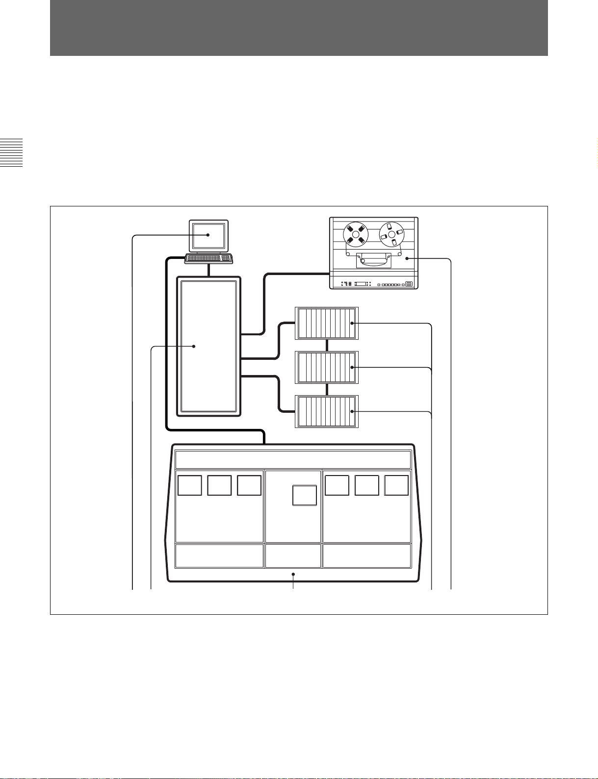
The OXF-R3 is a ‘high end’ digital audio mixing console system. It
comprises four main components:
• Control Console with Modular Control Surface
• Host Computer
• Signal Processing (SP) Rack
• Digital and Analogue I/O Racks
The following illustration shows a basic system concept diagram.
21
1 SP Rack
2 Host Computer
3 Multitrack Tape Recorder(s)
1-2 Chapter 1 Overview
5
System Concept diagram
4 Digital and Analogue I/O Racks
5 Control Console
4
3
Page 15

Control Console
Compared with traditional console designs, the OXF-R3 offers greater
flexibility within more compact dimensions by using an assignable control
surface.
Modular Control Surface
The control surface of the OXF-R3 makes extensive use of assignable
panels to provide a console of manageable size for either one or two
operators, whilst giving greatly increased functionality. The current
system is capable of controlling up to 96 full channels and 12 stereo return
channels. The modular system divides functionally into the master
section, located in the centre, and the channel sections located either side
of the master section.
Signal Processing (SP) Rack
The SP rack is designed to use the minimum number of signal processing
cards depending on the system size. A high level Software Design Tools
System is used to generate automatically the low level software microcode
which runs the SP system. Data links to and from the control console are
via Ethernet connections, whilst a MADI interface is used between the SP
rack and the I/O racks. Additional bandwidth, available within the MADI
signal, is used to pass data for purposes such as remote control of analogue
amplifier gain.
Chapter 1 Overview
Digital and Analogue I/O Racks
The I/O racks are designed to be located close to the equipment with which
they interface. Each I/O rack can contain a mix of up to 56 high quality
analogue inputs and/or outputs on 10 analogue I/O cards. Each analogue
card handles 4 or 8 inputs and 4 or 8 outputs according to its type. A mix
of input and output cards in the same I/O rack may, for example, allow cue
outputs for headphones to be local to appropriate microphone sources.
The digital and analogue I/O are housed in a single rack type. Digital I/O
has the same capability as the analogue, of up to 56 inputs and 56 outputs
per rack via AES/EBU and SDIF-2 (24) modules. The digital I/O system
also includes modules for Timecode, 9-Pin, GPI and MIDI. MADI
connections may be made directly to the SP rack.
Machine Control
Machine control for the OXF-R3 is accomplished via Sony 9-Pin control
and third party devices such as the “motionworker”, supplied by
Motionworks Ltd.
Note:
Refer to the Appendixes in this manual for further details of OXF-R3 capabilities.
Chapter 1 Overview 1-3
Page 16
1-1 Overview
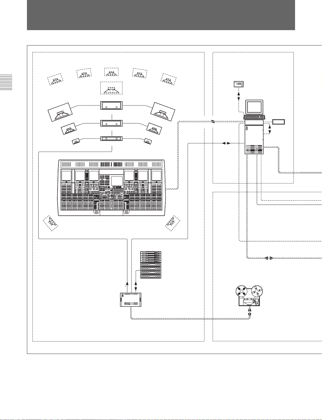
1-2 Data Flow
1
Chapter 1 Overview
2
(LC)
L
C
SUB
CR MONITORS 1
CR MONITORS 2
CR MONITORS 3
(RC)
R
CONTROL FOR SP AUDIO PROCESSING & MACHINES
SYSTEM STATUS & DISPLAY DATA
MADI
AUTOMATION
MEDIA
HOST COMPUTER
MODEM
SP RACK
4
SURROUND L SURROUND R
AUDIO AUDIO
I/O RACK
Sample installation illustrating Audio & Control Data flow
FX RACK
1 Control Room
2 TRACK ANALOGUE
GPI
AUDIO
MADI
1-4 Chapter 1 Overview
2 Rack Room
Page 17
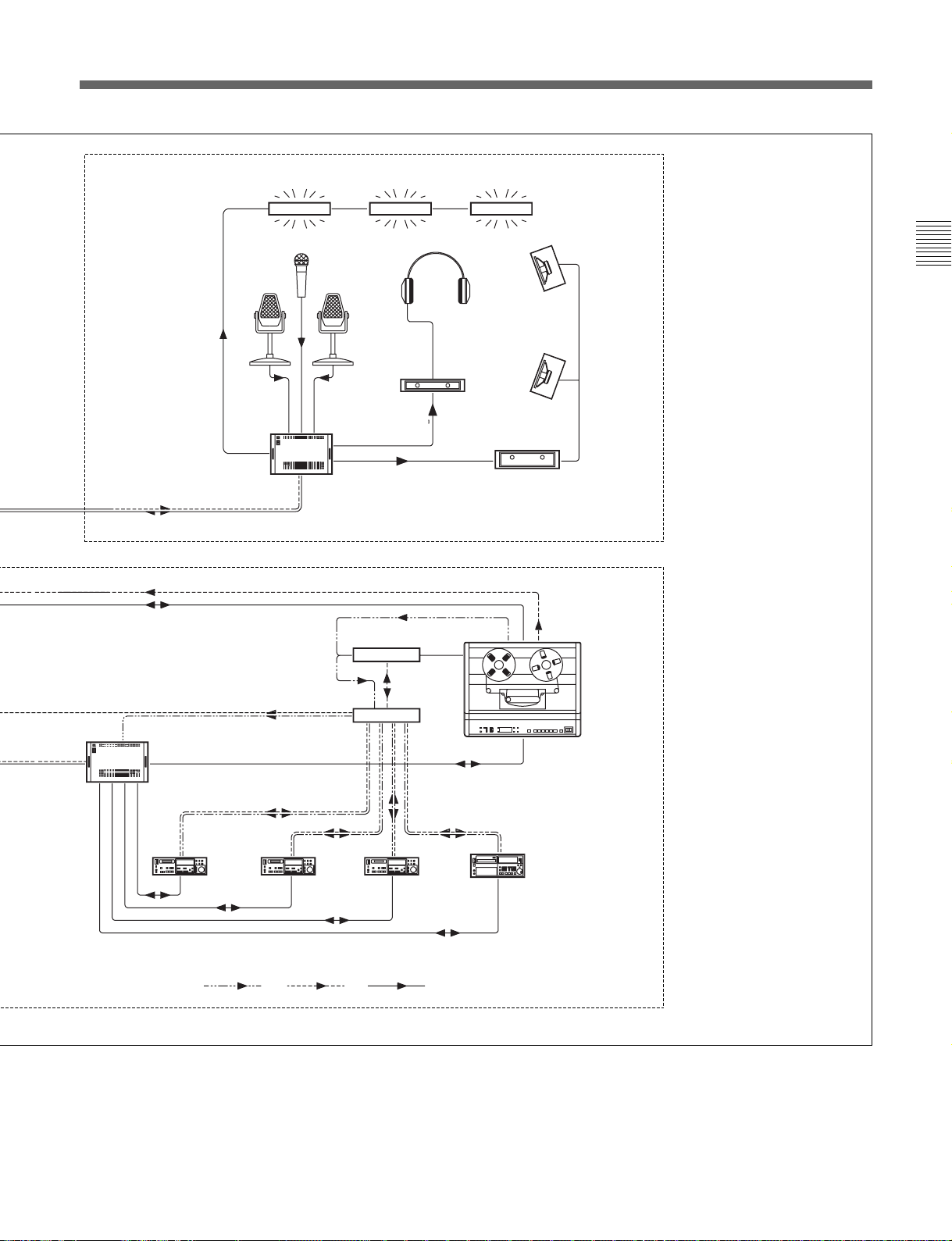
3
GPI
RECORD REHEARSE CUE
LISTEN
STUDIO
L/S
Chapter 1 Overview
GAIN
MADI
FS
MADI
I/O
RACK
AES/EBU
I/O RACK
MOTIONWORKER PROTOCOL
MASTER TC
TRANSPORT 9P
TC
TRANSPORT 9P
PCM-7050
DAT
AES/EBU
AUDIO
TC
PCM-7050
DAT
AES/EBU
AUDIO
AUDIO
TC
SYNCHRONISER
TC
MOTIONWORKER
TC
TRANSPORT 9P
FOLDBACK
GPI
RECORD REMOTES & TALLIES
TRANSPORT 9P
TC
PCM-7050
DAT
AES/EBU
PCM-3348 48 TRACK
PCM-9000
MASTERDISC
FS OUT
3 Studio
4 Machine Room
TIME CODE CONTROL DATA AUDIO DATA
Chapter 1 Overview 1-5
Page 18
1-1 Overview
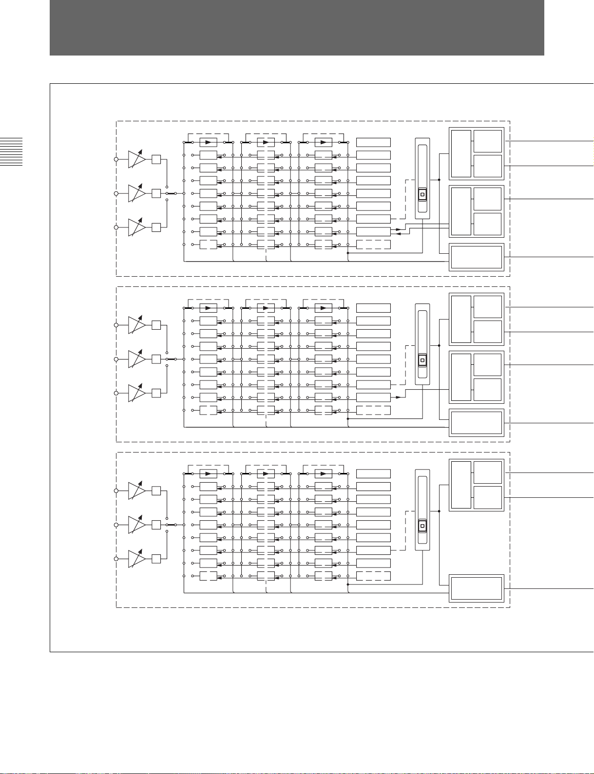
1-3 Signal Flow
Chapter 1 Overview
MIC
M/T
LINE
MIC
M/T
LINE
Ø
Ø
Ø
CHs 1-48
Ø
Ø
Ø
CHs 49-96
SELECTOR 1 SELECTORS 2-7 SELECTOR 8
SELECTOR 1 SELECTORS 2-7 SELECTOR 8
BYPASS
FILTERS
5 BAND EQ
DYNAMICS
INSERT
DELAY FX
FADER
MULTITRACK
FUTURE SP
BYPASS
FILTERS
5 BAND EQ
DYNAMICS
INSERT
DELAY FX
FADER
MULTITRACK
FUTURE SP
ST.
LCRS
5.1
7.1
ST
LCRS
5.1
7.1
UP
TO 8
STEMS
AUXILIARY
SENDS 1-24
ST.
LCRS
5.1
7.1
ST
LCRS
5.1
7.1
UP
TO 8
STEMS
AUXILIARY
SENDS 1-24
MAIN
OUTPUT
BUS
SUPER
SEND GPs
1-16
BUSSES
1-48
48 M/T
SENDS &
RETURNS
CUE &
MAIN
OUTPUT
BUS
SUPER
SEND GPs
1-16
BUSSES
1-48
48 M/T
DIRECT
OUTPUTS
CUE &
M/T
M/T
MIC
M/T
LINE
OXF-R3 signal flow
SELECTOR 1 SELECTORS 2-7 SELECTOR 8
Ø
Ø
Ø
RETURN CHs 97-120
BYPASS
2 BAND EQ
INSERT
DELAY FX
FADER
FUTURE SP
ST.
LCRS
5.1
7.1
CUE &
AUXILIARY
SENDS 1-24
MAIN
OUTPUT
BUS
SUPER
SEND GPs
1-16
1-6 Chapter 1 Overview
Page 19

MAIN OUTPUT BUS - STEREO, LCRS, 5.1 or 7.1
16 SUPER SEND GROUPS - MONO, STEREO, LCR, LCRS, 5.0, 5.1, 7.0 & 7.1
48 MULTITRACK BUSSES - Up to 8 MULTI-CHANNEL STEMS
CUE & AUXILIARY SENDS 1-24
Chapter 1 Overview 1-7
LISTEN MIC 1
TALKBACK
MONITOR SECTION
FOLDBACK 1
FOLDBACK 2
FOLDBACK 3
FOLDBACK 4
TALKBACK 1
STUDIO LS 2
AFL
PFL
STUDIO LS 1
SOLO
LS 3
MONITOR LS
MONITOR INPUTS
SURROUND
4 X 8 WIDE
LS 2
CONTROL ROOM
MONITOR LS
EXTERNAL SOURCES 9-12
MONITOR LS
EXTERNAL SOURCES 1-8
8 X STEREO MONITOR
INPUTS
LS 1
MAIN
CONTROL ROOM
Chapter 1 Overview
Page 20

Page 21

Chapter 2 – Powering The OXF-R3
This chapter provides step-by-step procedures for starting up the OXF-R3,
including the power-up sequence and the booting of the Host Computer. It
also includes the procedure for controlled shutdown of the OXF-R3.
Chapter 2 Contents
2-1 OXF-R3 Start-Up ........................................................................... 2-2
2-1-1 Start-up Procedure ............................................................... 2-2
2-2 OXF-R3 Shutdown ......................................................................... 2-4
2-2-1 Shutdown Procedure ............................................................ 2-4
Chapter 2 Powering The OXF-R3
Chapter 2 Powering the OXF-R3 2-1
Page 22

2-1 OXF-R3 Start-Up Procedure
2-1 OXF-R3 Start-Up
CAUTIONS:
1. Before starting-up the OXF-R3, check that all Monitor
Loudspeaker Power Amps are turned off or muted.
2. Switch on equipment in the sequence given here, to ensure troublefree start-up.
Chapter 2 Powering The OXF-R3
2-1-1 Start-Up Procedure
1. Check that the motionworker and Lynx Time Code Module are already
switched on and running normally.
2. Switch on the power to the SP Rack.
3. Switch on the power to the Host Computer.
4. Switch on the power to the I/O Racks.
Note:
It is important that the I/O racks are switched on in the sequence of the Sync
Clock wiring loop connected to the clock inputs of the I/O Racks.
5. The Host Computer performs its start-up and self-test routines. At the
end of these routines, a triple chevron prompt >>> should be displayed
on the monitor.
6. Type b then press {RETURN} to start the boot-up process for the
OXF-R3 system.
2-2 Chapter 2 Powering the OXF-R3
Note:
If your Host Computer has been configured for Auto-boot (an option at set-up),
the triple chevron prompt will not be displayed and boot-up will proceed
automatically.
7. At the end of the boot-up procedure, the Login field will be displayed
on the monitor.
8. Now switch on the power to the control panel. All 7 LCD screens will
show activity as programs are downloaded from the Host Computer to
the computers within the console. When downloading is completed,
an ‘X’ is displayed in the centre of each screen.
Page 23

9. Log in at the Host Computer. Note that the user name and password
below are the system defaults.
Type sm (case-sensitive) then press {RETURN}.
Type in the password: oxf-r3 (case-sensitive), then press {RETURN}.
Notes:
1 oxf-r3 is the default password. This may be changed but its modification must
be carried out with help from Sony personnel.
2 Login can be initiated while programs are still being downloaded from the Host
Computer. It is not necessary to wait until all the console LCD screens are
displaying ‘X’ in their centres.
10. Once logged-in, a window is displayed on the monitor of the Host
Computer. Use the mouse to move the cursor into this window entitled
STIF. Note that the window surround changes colour from green to
red, to indicate that this is now the active window.
11. Check that the console LCD screens are all displaying ‘X’ before
proceeding, then:
Type: run_r3 (case-sensitive) then press {RETURN}.
Chapter 2 Powering The OXF-R3
12. Observe that the centre LCD screen in the console displays a summary
of the processes being executed by the Host Computer which are
displayed in greater detail on the monitor.
13. When the loading of the Netlist is complete, the centre screen of the
console displays the OXF-R3 logo.
14. Switch-on is now complete, but wait until all controls on the control
panel are initialised (indicated by their lighting up) before operating
the system.
Chapter 2 Powering the OXF-R3 2-3
Page 24

2-2 OXF-R3 Shutdown Procedure
2-2 OXF-R3 Shutdown
CAUTION:
Turn off or mute all monitor amplifiers connected to the OXF-R3.
Unless the OXF-R3 is to remain switched off for a prolonged period, it
will be more convenient to leave the Clock Synchronisation source
running.
Chapter 2 Powering the OXF-R3
2-2-1 Shutdown Procedure
1. At the centre LCD screen on the OXF-R3 control surface, use the
appropriate softkey to select SYSTEM.
Note:
If necessary, retrace a number of steps through the screens hierarchy to reach this
point. Refer to the Screens Structure diagram in Chapter 5 for detailed
information on the screen page hierarchy.
2. On the SYSTEM screen page, click on SYSTEM SHUTDOWN on the
right side of the screen if it is displayed.
3. If SHUTDOWN is not displayed click on the ‘User field’ for a pop-up
and click on ADMIN. Enter the admin password (default is admin in
lower case) and click on OK. The field which includes SYSTEM
SHUTDOWN will then appear in the right side of the screen. Click on
it. A dialogue box will appear on the screen to request confirmation of
Shutdown and ask if current work should be saved. Press {ENTER} on
the Control Keyboard or click on OK.
4. The console now shuts down and power to the control surface can be
turned off but the STIF and UNIX windows on the Host Computer
monitor remain.
2-4 Chapter 2 Powering the OXF-R3
5. On the Host Computer, place the mouse cursor in the STIF window
and
Type: exit (case-sensitive) then press {RETURN}.
Note:
It is important to switch off the power to the control surface for a minimum of 10
seconds before attempting a re-start.
6. For a re-boot, turn on the power to the control surface again and follow
the Start-Up Procedure, in the previous section, from step 11. For a
complete power-down, continue with step 7 in this section.
Page 25

7. To shut down the Host Computer, place the cursor in the UNIX
window, and
Type: su (case-sensitive) which stands for ‘superuser’, then press
{RETURN}.
8. At the ‘password’ prompt:
Type the superuser password, oxf-r3 (case sensitive) is the default,
then press {RETURN}.
9. At the prompt which follows:
Type: shutdown -h now (case sensitive), then press {RETURN}.
10. Wait for the >>> prompt to appear before powering down the Host
Computer, SP and I/O Racks.
Chapter 2 Powering the OXF-R3
Chapter 2 Powering the OXF-R3 2-5
Page 26

Page 27

Chapter 3 – Getting Started
This chapter gives an overview of the control surface layout and
functionality. It also provides easy to follow, step-by-step procedures for
basic operations of the console. These are designed to help the
experienced operator become familiar with the OXF-R3 within a short
period of time.
Chapter 3 Contents
3-1 The Control Surface...................................................................... 3-2
3-2 Fader Paging.................................................................................... 3-8
3-3 Assignable Channel Processing ...................................................... 3-9
3-4 Input Channel, Equaliser and Filters ............................................. 3-10
3-5 Free Assign Area and Dynamics ................................................... 3-11
3-6 Multitrack, Routing for Multitrack, Super Send Groups and
Multi-Format ............................................................................... 3-12
3-7 Sends ............................................................................................. 3-13
3-8 Select To Faders .......................................................................... 3-14
3-9 Select To Pans .............................................................................. 3-17
3-10 Basic Console Operations ........................................................... 3-18
3-10-1 To Route a Mic or Line Input to the Main Output Bus ... 3-19
3-10-2 To Set Up a Super Send Group from Channel Inputs...... 3-20
3-10-3 To Send Signals to Tracks on Tape ................................. 3-21
3-10-4 To Monitor Signals to and from Tape.............................. 3-22
3-10-5 To Set Up a Stereo Headphone Mix for Foldback 1 O/P 3-23
3-10-6 To Equalise Signal Feeding the Multitrack ..................... 3-24
3-10-7 To Equalise Monitor Signal Post Multitrack ................... 3-25
3-10-8 To Insert Dynamics Pre Multitrack Send......................... 3-26
3-10-9 To Insert Dynamics Post Multitrack Return .................... 3-27
3-10-10 To Bounce Tracks ............................................................ 3-28
3-10-11 To Set Up Super Send Groups from Multitrack .............. 3-29
3-10-12 To Set Up a De-Esser Using Dynamics Side-Chain EQ.. 3-30
3-10-13 To Link Compressor Side-Chains in a Group.................. 3-31
3-10-14 To Link Compressor Side-Chains so that One Channel
Controls a Second Channel.............................................. 3-32
Chapter 3 Getting Started
Chapter 3 Getting Started 3-1
Page 28

3-1 The Control Surface
3-1 The Control Surface
The OXF-R3 comes in two configurations known as the 24-C-24 and the
24-C-0. The basic elements are illustrated below.
Chapter 3 Getting Started
1
2 3
24-C-24 Control Surface Configuration
4
1
24-C-0 Control Surface Configuration
4
2
3-2 Chapter 3 Getting Started
Page 29

Control Surface Elements
11
1 Left hand 24 Fader Channels Section
11
22
2 Central Master Section
22
33
3 Right hand 24 Fader Channels Section
33
44
4 Meter Bridge
44
The Control Surface in general
A key feature of the OXF-R3 is its Assignable Panels, which divide further
into four basic areas:
• INPUT CHANNEL, EQUALISER and FILTERS
• FREE ASSIGN AREA & DYNAMICS
• MULTITRACK, ROUTING for MULTITRACK, SUPER SEND
GROUPS and MULTI-FORMAT
• SENDS (For Foldback and Effects feeds)
The channel section panel areas are mirrored so that every function can be
operated from either side of the console, allowing two operators to work
on the same channels simultaneously. The ability to have 48 channel
faders and their related functions on view at all times is an advantage but
everything can be operated from just one 24 fader channel bank and the
centre section, as in the more compact 24-C-0 design.
Use the following two diagrams for reference to identify each area as it is
explained whilst reading through this manual.
Chapter 3 Getting Started
Operation of the control surface can be split into 5 main areas:
1. USE OF FADER PAGING
2. USING ASSIGNABLE SIGNAL PROCESSING
3. SELECT TO FADERS FUNCTIONS
4. SELECT TO PANS FUNCTIONS
5. BUILDING SIGNAL PATHS
(Described in detail in Chapter 4)
Chapter 3 Getting Started 3-3
Page 30

3-1 The Control Surface
1
OXF-R3 Assignable Channel Areas
3-4 Chapter 3 Getting Started
1 Left hand assignable channel controls
2 Right hand assignable channel controls
Page 31

2
Chapter 3 Getting Started
Chapter 3 Getting Started 3-5
Page 32

3-1 The Control Surface
1
Chapter 3 Getting Started
3
9
!º
3
4
!¡
3
5
6
7
8
2
!•
OXF-R3 panel locations
3-6 Chapter 3 Getting Started
!£
!¢
!™
!ª
@™
!∞
@º
!§
@¡
@£
@º
!¶
Page 33

1 Meter Bridge – Mono Meters
3
!¡
4
3
!º
9
3
1
2 Meter Bridge – Stereo Meters
3 Channel Screens (6)
4 Routing Panels
5 Multi-Channel Set-up Panel
6 Super Send Group Masters
7 Sends Masters
Chapter 3 Getting Started
8 Central Control Screen
9 Sends Panels
0 Free Assign Area/Dynamics
Panels
!¡Input & Equaliser Panels
!™ Multitrack Panels
!£Track Monitoring Controls
!¢Assignable Pan Knobs
!∞
@™
!ª
!™
!£
!¢
!∞ Select to Pans Panels
!§Monitor & Foldback Panel
!¶Control Keyboard & Automation
Controls
!•Assignable Channel Faders
!ªSelect to Faders Panels
@º Multi-Purpose Faders
@¡ Main Output Fader
@™ Trackerballs
@£ QWERTY Keyboard (beneath
sliding cover)
!•
Chapter 3 Getting Started 3-7
Page 34

3-2 Fader Paging
3-2 Fader Paging
Chapter 3 Getting Started
The OXF-R3 has 48 (or 24 on a 24-C-0) channel faders on its control
surface but Fader Paging enables control of a much greater number of
channels. Fader Paging allows banks of 24 channels to be selected on
either side of the centre section at any time. The diagram illustrates how
Fader Paging relates to a standard in-line console. Use the SELECT TO
FADERS panel to select the fader bank required. Within that panel, there
are a number of buttons marked CHS 1-24, CHS 25-48 and so on. There is
a SELECT TO FADERS panel for each set of 24 channel faders, left and
right of the centre section.
96 CHANNEL IN-LINE CONSOLE
1-24 25-48 49-72
CENTRAL
MASTER
SECTION
73-96
SELECT TO FADERS
PANEL
SELECT TO FADERS
SEND1SEND2SEND3SEND4SEND5SEND6SEND7SEND
SEND9SEND10SEND11SEND12SEND13SEND
SEND18SEND19SEND20SEND21SEND22SEND23SEND
SEND
17
SHOW
SUB
SUPER
VALUE
LEVEL
SGs 1-16
INPUT
GROUP
M/T
GAIN
TRIM
SEND
M/T
CHANs
MON
CHS
CHS
CHS
1-24
25-48
49-72
CHS
CHS
73-96
97-120
ABS & TRM
SELECT L
TO CUTS
MASTERS
ABS & TRM
SELECT R
TO FADs
MASTERS
Paging of Faders for the left side of the control surface
8
SEND15SEND
16
14
24
SEL
SENDS
1-8
SENDS
9-16
SENDS
17-24
SUPER
SGs 1-8
SUPER
SGs 9-16
GROUPs
1-8
GROUPs
9-16
GROUPs
17-24
GROUPs
25-32
CHS
1-24
CHS
73-96
ABS &TRM
TO FADs
ABS &TRM
TO CUTS
CHS
25-48
CHS
97-120
CHS
49-72
SELECT L
MASTERS
SELECT R
MASTERS
3-8 Chapter 3 Getting Started
Page 35

3-3 Assignable Channel Processing
Once the appropriate bank of 24 channel faders is selected, individual
channel controls can be adjusted. To do this, press the ACCESS button
below the fader for the channel required. Then all the ASSIGNABLE
PANELS belong to the channel, displaying its settings. Adjust as
necessary.
As can be seen from the diagram, the functions on an in-line vertical
channel strip become horizontal on the OXF-R3. In other words, the
whole panel is equivalent to an exceptionally comprehensive channel strip.
This is assigned to each channel individually, simply by pressing the
appropriate channel ACCESS button.
MULTI-FORMAT
ROUTING
Chapter 3 Getting Started
ROUTING
SENDS 1-24
FREE ASSIGN AREA DYNAMICS
MULTITRACK
EQUALISER & FILTERS
INPUT CHANNEL & INSERTS
DYNAMICS
EQ &
FILTERS
AUX SENDS
MULTITRACK
ACCESS
Assignable panels
Chapter 3 Getting Started 3-9
Page 36

3-3 Assignable Channel Processing
3-4 Input Channel, Equaliser and Filters
Chapter 3 Getting Started
SLOPE
The Input Channel section is much more flexible than a conventional inline analogue channel strip in that it allows processing elements to be
configured in almost any order. The eight boxes towards the bottom of the
panel enable up to eight functions to be placed in each channel path with
individual IN switches. The order of the processes can be totally different
on every channel, as desired.
The 5 Band Equaliser and High & Low Filters sections are independent
and can be assigned separately within the channel signal path. To view
parameters and curves whenever EQ and Filters are in use, access the EQ
page available on the channel screens.
Various EQ options are available which are selected using the {IN} and
{+} / {-} buttons situated in the upper middle section of the panel.
EQUALISER & FILTERS
LMF
FREQ
LF
Q
XXXXXXXX
IN
HMF
QFREQ
SLOPE
HF
FREQ
FREQ
IN
Q
LF
IN
AB
FREQ
MF
IN
Q
IN
INPUT CHANNEL & INSERTS
XXXXXXXX XXXXXXXX XXXXXXXX XXXXXXXX
O
MIC
M/T
LINE
GAIN
IN
IN
IN
XXXXXXXXXXXXXXXX XXXXXXXX XXXXXXXX
IN
FREQ
FREQ
IN
Q
HF
XXXXXXXX
IN
IN
IN
IN
3-10 Chapter 3 Getting Started
Input Channel & Inserts, Equaliser and Filters panel
Page 37

3-5 Free Assign Area and Dynamics
3-5 Free Assign Area and Dynamics
FREE ASSIGN AREA & DYNAMICS
THRESHLD
ATTACK
DYNAMICS
GATE EXP
80
60
40
35
30
25
20
15
10
5
COMP LIMIT
20
18
16
14
12
10
8
6
4
2
HOLD
RELEASE
RANGE
ACCESS
ACCESS
ACCESS
ACCESS
ACCESS
ACCESS
LOCAL
LOCAL
GATE
EXPANDER
COMPRESS
LIMITER
S–C EQ
The Dynamics function area (lower left) contains:
SIG EQ
S–C EQ
IN
IN
IN
IN
IN
IN
O/L
0
4
8
12
16
20
26
32
40
50
METERS
HOLD
INPUT
OUTPUT
IN
IN
IN
IN
IN
IN
Free Assign Area & Dynamics panel
DELAY
Chapter 3 Getting Started
ACCESS
ACCESS
ACCESS
ACCESS
ACCESS
ACCESS
• GATE
• EXPANDER
• COMPRESSOR (there are a number of Compressor options)
• LIMITER
• SIDE-CHAIN EQUALISER (S-C EQ).
Each section of the Dynamics has its own side-chain and allows very
comprehensive control, equivalent to that of high specification units. All
four side-chains operate on a single gain control element. The Side-Chain
EQ is a fully parametric 2-band element which may be inserted in three
ways:
• in the Dynamics Side-Chain only
• in the Signal Path only as a second EQ
• in the Signal Path and the Side-Chain.
The current Free Assign Area (lower right) contains:
• DELAY Effect
This area includes space for additional effects as and when software
upgrades are introduced in the future.
Chapter 3 Getting Started 3-11
Page 38

3-6 Multitrack, Routing for Multitrack, Super Send
3-6 Multitrack, Routing for Multitrack, Sub-Groups and Multi-Format
Chapter 3 Getting Started
Groups and Multi-Format
MULTI-FORMAT Buttons
These routing buttons have a layout matching a set of
MULTI-FORMAT
L
L
ROUTE TO TRACKS
13 14 15 16
17 18 19 20
21 22 23 24
25 26 27 28
29 30 31 32
33 34 35 36
37 38 39 40
41 42 43 44
45 46 47 48
SSGs 1-8
R
CR
C
C
SUB
L-S R-S
MONO
ROUTING
1234
5678
9 101112
1
SSGs 9-16
3112101
4125
9
14
A
E
8167156
STEMS
BFCGD
BOUNCE
2MULTITRACK
13
H
7.1 surround LS. Their function depends on what is
selected to the faders at the SELECT TO FADERS
panel. In other words, they set the destinations for the
signals currently passing through the faders.
ROUTING Buttons 1-48,
Two sets of buttons on each side of the console allow
channel sources to be assigned to Multitrack Group
Busses 1-48 ({GRP} - default) or Direct Outputs
({DIR} ). The routing for 48 channels can be displayed
simultaneously by showing 8 channels on each of the
associated six channel screens, three per side. The
screens display further channels automatically,
consistent with fader paging.
SSGs 1-8 & SSGs 9-16
These buttons allow post channel fader and pan feeds
to Super Send Groups 1-16. They are paged and
legends lit depending on whether {SUPERSGs1-8} or
{SUPERSGs9-16} is selected in the centre section.
STEM Selectors
These buttons are operational in Multi-Format Mode
to assign channel outputs to stems set up on the
multitrack busses.
{A}{A}
{A} -
{A}{A}
{H}{H}
{H}
{H}{H}
{GRP}{GRP}
{GRP} &
{GRP}{GRP}
{DIR}{DIR}
{DIR}
{DIR}{DIR}
MULTITRACK
GROUP
TRIM
AFL
SOURCE
INSERT
IN
ACCESS
DIV
SUR.
L/R
PAN
LR
LEVEL
AFL CUT
IN
0
+10
Routing for Multitrack, Super Send Groups & Multi-Format
and Multitrack panels
{BOUNCE}{BOUNCE}
{BOUNCE} Push-Button
{BOUNCE}{BOUNCE}
Redirects the output of a channel from the Main
Output Bus to the multitrack routing buttons in the
MULTITRACK section for bounce-down purposes.
One of the stems A-H must be selected to bounce down a
surround source or a signal with surround panning.
MULTITRACK
This panel contains controls related to the multitrack
except individual track remotes and monitor switching.
These are above the pan controls in line with their
equivalent number channel faders. All level controls
can be assigned to faders. Surround panning is
available at this panel in parallel with the joysticks and
individual pans above the faders. These pan controls
are operational on what is selected to the faders at the
SELECT TO FADERS panel.
The OXF-R3 allows the multitrack to be used ‘in-line’
for normal record/remix work or ‘on-the-side’ where a
live mix requires a multitrack backup. A separate
stereo monitor bus is included specifically for monitoring
the multitrack when used in parallel with a live mix.
3-12 Chapter 3 Getting Started
Page 39

3-7 Sends
3-7 Sends
There are currently 24 mono Sends that can be linked as odd/even pairs,
set up at the SEND OUTPUTS 1-24 panel in the centre section, to provide
up to 12 stereos. The levels to the busses can be set via the individual
dedicated controls on the channels SENDS 1-24 panels for each channel
individually. Alternatively Sends can be assigned, one bus at a time, to the
faders or assignable knobs (PANs). This allows a mix to an effect or
foldback to be set up using the faders or a row of knobs on a console-wide
basis. The source points for each Send can be set individually on each
channel or on a console-wide basis.
Chapter 3 Getting Started
SENDS 1-24
SOURCE
SELECT
∞∞∞∞ ∞∞∞∞
∞∞∞∞ ∞∞∞∞
ONON ONON ONON ONON
∞∞∞∞ ∞∞∞∞
SELECT SOURCE FOR
ONONONONONONONON
ONONONONONONONON
Sends 1-24 panel
Chapter 3 Getting Started 3-13
Page 40

3-8 Select T o Faders
3-8 Select To Faders
Chapter 3 Getting Started
The main purpose of faders on a mixing console is to control the levels of
the signals through the channels. Once a balance is achieved, the fader
positions give an extremely useful graphical representation.
It is common with in-line analogue console channel strips to split the
signal flow into channel and monitor paths with a fader for each. The
OXF-R3 takes this concept a stage further, allowing all level and gain
control to be accomplished using the faders. This is achieved by assigning
the faders to all gain and level functions via the SELECT TO FADERS
panel.
INPUT GAIN
Select to Faders
SENDS
GROUP TRIM
M/T SEND
CHANNEL FADER
3-14 Chapter 3 Getting Started
Page 41

As an example, on the SELECT TO FADERS panels, adjacent to the
channel faders on either side of the centre section, there are buttons
marked:
11
{CHANS}{CHANS}
1
{CHANS}
11
{CHANS}{CHANS}
22
{M/TSEND}{M/TSEND}
2
{M/TSEND}
22
{M/TSEND}{M/TSEND}
The default is {CHANS} , which assigns the faders to the channel outputs
when they control the level to the Main Output Bus. Selecting M/T SEND
is equivalent to selecting the ‘small fader’ function to the OXF-R3 faders.
The combined use of Fader Paging and the Select to Faders functionality
allows control of all channel level functions, using the 48 conveniently
placed, high quality faders in the left and right channels sections.
Chapter 3 Getting Started
1
2
Select To Faders panel layout
Chapter 3 Getting Started 3-15
Page 42

3-8 Select T o Faders
Chapter 3 Getting Started
Exploiting this approach even further, the faders can also be assigned to
control Input Gain, Group Trim and all Send Bus levels.
The Select to Faders diagram at the beginning of this section is a visual
guide showing how the OXF-R3 accommodates conventional in-line
channel strip level controls on its faders. Note that all level controls are
still available in parallel within the assignable panels in a more
conventional manner.
This approach is very convenient for checking foldback or effects send
balances. The faders and their selector system are very close at hand,
allowing any balance to be quickly checked at a glance and adjusted.
A copy function allows the user to take the balance set-up as the monitor
mix and transfer it to any of the Send Bus mixes. The fader balance copy
function applies to M/T Send Faders to Channel Faders and vice versa.
This is described in detail in Chapter 6.
The 16 centre section master faders are also assignable in two groups of 8
faders. They are assigned via the SEL area on the SELECT TO FADERS
panel and may control:
• SENDs (Send Master levels)
• SUPER SGs (Super Send Group master levels)
• GROUPs (VCA style control group masters)
3-16 Chapter 3 Getting Started
Page 43

3-9 Select To Pans
3-9 Select To Pans
The Pan Knobs above the faders are assignable in a similar manner to the
faders. Although their primary job is panning, they can also be used to
perform all channel level adjustments, such as input gain settings and Send
Bus levels. They are really Definable Knobs rather than just Pans.
As can be seen in the diagram below, the SELECT TO PANS panel
performs a function for the Pans similar to that of the SELECT TO
FADERS panel for the faders. All equivalent level and gain control
functions, on an in-line channel strip, may be assigned to the row of
Definable Knobs whose default setting is channel Pan.
A typical set-up could have Mic Gain controlled by the knobs, whilst the
faders control the M/T Send. With this set-up, all levels are easily adjusted
during tracking. Remember that dedicated knobs are always available on
the assignable panel areas in parallel for all level controls.
INPUT GAIN
Chapter 3 Getting Started
Select to Pans
SENDS
GROUP TRIM
M/T SEND
PAN
Chapter 3 Getting Started 3-17
Page 44

3-10 Basic Console Operations3-10 Basic Console Operations
3-10 Basic Console Operations
Chapter 3 Getting Started
General
The following series of illustrations and brief step by step procedures are
designed to allow new OXF-R3 operators to begin using the console in a
very short space of time, without having detailed knowledge of the system.
System Set-up
The examples shown assume that signal sources, such as microphones, line
level signals and multitrack or hard disc recorder, are already connected
and routed to appropriate inputs, with machine control in place. They also
assume that the control room monitor LS are hooked up to the OXF-R3
system.
Main Bus Set-up
The Main Output Bus can be set for the following ‘widths’: Stereo, LCRS,
5.1 and 7.1. For the purposes of the examples, the fire-up default of Stereo
will be assumed.
3-18 Chapter 3 Getting Started
Page 45

3-10-1 To Route a Mic or Line Input to the Main Output Bus
Chapter 3 Getting Started
134562
1 Press {ACCESS} for the desired Channel.
2 At the Input Channel & Inserts panel, press either
{MIC} or {LINE} as required, and set the input GAIN
knob to a suitable setting.
3 Make sure {CHANS} is selected on the Select To
Faders panel (fire-up default).
4 At the Routing panel, select {L} and {R} (fire-up
default) if not already lit.
5 Adjust the level to the Main Output Bus with the
Channel Fader.
6 Open the Main Fader and turn up the CR Monitor
level.
Chapter 3 Getting Started 3-19
Page 46

3-10 Basic Console Operations
3-10-2 To Set Up a Super Send Group from Channel Inputs
Chapter 3 Getting Started
124,8 63 75
1 Press {ACCESS} for the first Channel to be routed
to a Super Send Group (SSG).
2 Make sure {CHANS} is selected on the Select To
Faders panel (fire-up default).
3 Make sure {SUPERSGs1-8} is selected in the SSG
masters section.
4 At the Routing panel, de-select {L} and {R} .
5 At the same panel, select the SSGs required,
{1/9} and {2/10} in this case.
3-20 Chapter 3 Getting Started
6 At the Select To Faders panel (SEL section), select
{SUPERSGs1-8} , then adjust the Fader to 0dB in
the Central Faders panel.
7 Above the SSG 1 level knob select {MAIN} and its
{ACCESS} .
8 At the top of the Routing panel select {L} .
9 Repeat steps 7 and 8 for SSG 2 but select {R} at
the Routing panel.
10 Repeat steps 1 to 5 for further channels.
Page 47

3-10-3 To Send Signals to Tracks on Tape
Chapter 3 Getting Started
1346527
1 Press {ACCESS} for the desired Channel.
2 At the Input Channel & Inserts panel, press either
{MIC} or {LINE} as required, and set the input GAIN
knob to a suitable setting.
3 At the same panel, select ‘MULTI’ in one of the
eight windows. Do this using the {+} and {–}
buttons, and then press the large {IN} button.
4 At the Routing panel, select the tracks required in
the ROUTE TO TRACKS section. The Pan
works across odd and even numbers in Stereo.
5 To pan between tracks, press {CUT} , if it is lit
which sets the pan into operation, and adjust the
Pan Knob accordingly.
6 On the Select To Faders panel, press {M/TSEND} .
7 Adjust the level to tape using the Fader. Check the
meter level for the track to which the signal is
routed.
Chapter 3 Getting Started 3-21
Page 48

3-10 Basic Console Operations
3-10-4 To Monitor Signals To and From Tape
Chapter 3 Getting Started
1247 65 3
1 Press {ACCESS} for the desired Channel.
2 Select {CHANS} on the Select To Faders panel
(fire-up default).
3 At the Input Channel & Inserts panel, select
‘MULTI’ in window number 4 using the {+} and
{–} buttons either side. Select its large {IN}
button to insert the multitrack into the signal path.
4 At the Pans panel, press {SEND} to select the signal
being fed to tape
3-22 Chapter 3 Getting Started
5 Or press {SEND} to select the signal from tape.
6 Open the Main Fader and turn up the CR Monitor
level.
7 Use the Channel Fader to adjust monitor level via
the Main Output Bus.
Page 49

3-10-5 To Set Up a Stereo Headphone Mix for Foldback 1 O/P
Chapter 3 Getting Started
1 At the Send Outputs 1-24 panel in the console
centre section, select {17-24} and then select
{STEREO} between Send Masters 17 and 18.
Sends 17 and 18 are a dedicated assignment to
Stereo Foldback 1. Select {AFL} to audition the
balance.
Note:
Send Masters 19 and 20 are assigned to Stereo Foldback
O/P 2; 21 and 22 to Foldback 3; 23 and 24 to Foldback 4.
2 At the Select To Faders panel, select {SEND17} or
{SEND18} . Pressing either will light both.
1243 5
3 Turn off the {CUT} buttons and set up the balance
and pan positions using the Faders and their Pans.
Turn off the Pan {CUT} if necessary.
4 At the Foldback Groups 1-4 section, located in the
central Monitor panel, adjust the LEVEL pot for a
suitable level in the headphones. (Make sure
{CUT} is not lit) Use the {T/BF/Back1} button to
talk to the artist(s).
5 The bus level itself, which defaults to unity gain,
can be adjusted using the central faders. On the
Select To Faders panel, SEL section, select
{SENDs17-24} and adjust Fader 17 or 18.
Chapter 3 Getting Started 3-23
Page 50

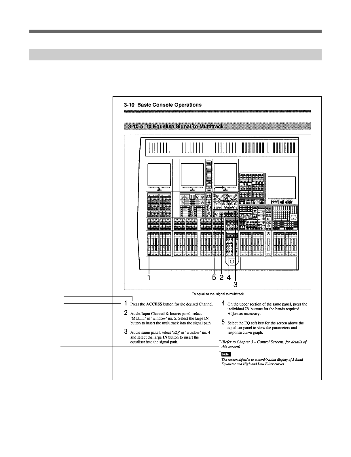
3-10 Basic Console Operations
3-10-6 To Equalise Signal Feeding the Multitrack
Chapter 3 Getting Started
13452
1 Press {ACCESS} for the desired Channel.
2 At the Input Channel & Inserts panel, select
‘MULTI’ in window number 4 using the {+} and
{–} buttons either side. Select its large {IN}
button to insert the multitrack into the signal path.
3 At the same panel, select ‘EQ’ in a window before
window 4, window 1 for example, and select the
large {IN} button to insert the equaliser into the
signal path before the multitrack.
3-24 Chapter 3 Getting Started
4 On the upper section of the same panel, select the
individual {IN} buttons for the bands required and
adjust as necessary.
5 Select the EQ softkey for the screen above the
equaliser panel to view the parameters and
response curve graph.
Page 51

3-10-7 To Equalise Monitor Signal Post Multitrack
Chapter 3 Getting Started
12453
1 Press {ACCESS} for the desired Channel.
2 At the Input Channel & Inserts panel, select
‘MULTI’ in window number 5 using the {+} and
{–} buttons either side. Select its large {IN}
button to insert the multitrack into the signal path.
3 At the same panel, select ‘EQ’ in a window after
window 5, window 8 for example, and select the
large {IN} button to insert the equaliser into the
signal path after the multitrack.
4 On the upper section of the same panel, select the
individual {IN} buttons for the bands required and
adjust as necessary.
5 Select the EQ softkey for the screen above the
equaliser panel to view the parameters and
response curve graph.
Chapter 3 Getting Started 3-25
Page 52

3-10 Basic Console Operations
3-10-8 To Insert Dynamics Pre Multitrack Send
Chapter 3 Getting Started
1245 36
1 Press {ACCESS} for the desired Channel.
2 At the Input Channel & Inserts panel, select
‘MULTI’ in window number 5 using the {+} and
{–} buttons either side. Select its large {IN}
button to insert the multitrack into the signal path.
3 At the same panel, select ‘DYN’ in a window
before window 5, window 4 for example, and
select the large {IN} button to insert the dynamics
processor into the signal path before the multitrack.
4 In the Dynamics section, located in the Free
Assign Area, select {IN} buttons for the processing
3-26 Chapter 3 Getting Started
required: Gate, Compressor, etc., indicated by 8
character dot displays.
5 On the LCD screen above the dynamics controls,
press the Dynamics softkey to view the parameters
and transfer curve graph.
6 The dynamics processing is set and displayed via
definable knobs and switches. Set their functions
via the local {ACCESS} keys according to the
processes in use. Adjust whilst viewing the
settings on the LCD screen. The settings for all
functions are displayed simultaneously.
Page 53

3-10-9 To Insert Dynamics Post Multitrack Return
Chapter 3 Getting Started
1245 36
1 Press {ACCESS} for the desired Channel.
2 At the Input Channel & Inserts panel, select
‘MULTI’ in window number 5 using the {+} and
{–} buttons either side. Select its large {IN}
button to insert the multitrack into the signal path.
3 At the same panel, select ‘DYN’ in a window after
window 5, window 8 for example, and select the
large {IN} button to insert the dynamics processor
into the signal path before the multitrack.
4 In the Dynamics section, located in the Free
Assign Area, select {IN} buttons for the processing
required: Gate, Compressor, etc., indicated by 8
character dot displays.
5 On the LCD screen above the dynamics controls,
press the Dynamics softkey to see the parameters
and transfer curve graph.
6 The dynamics processing is set and displayed via
definable knobs and switches. Set their functions
via the local {ACCESS} keys according to the
processes in use. Adjust whilst viewing the
settings on the LCD screen. The settings for all
functions are displayed simultaneously.
Chapter 3 Getting Started 3-27
Page 54

3-10 Basic Console Operations
3-10-10 To Bounce Tracks
Chapter 3 Getting Started
12356487
1 Press {ACCESS} for the desired Channel.
2 Make sure {CHANS} is selected on the Select To
Faders panel (fire-up default).
3 At the Routing panel, select {CHANS} . The {L}
and {R} buttons will be de-selected automatically
so that the channel output is no longer routed to the
Main Output Bus.
4 At the same panel select the destination tracks
required for the bounce, in the ROUTE TO
TRACKS section. Fader and Pan settings will be
retained (L to odd-numbered tracks, R to even).
3-28 Chapter 3 Getting Started
5 Select {ACCESS} for the first of the new tracks.
6 On the Input Channel & Inserts panel, select
‘MULTI’ and its large {IN} button in one of the
eight windows. Repeat for other bounce tracks.
7 Select the {SEND} on the channels to which the
bounce is routed, for a monitor signal for those
tracks.
8 Set the monitor level for the new track(s).
9 The original balance will be bounced down to the
selected multitrack tracks. Repeat steps 1 to 4 for
other tracks to be bounced down.
Page 55

3-10-11 To Set Up Super Send Groups from Multitrack
Chapter 3 Getting Started
124,8 63 75
1 Press {ACCESS} for the first Channel to be routed
to a Super Send Group (SSG).
2 Make sure {CHANS} is selected on the Select To
Faders panel (fire-up default).
3 Make sure {SUPERSGs1-8} is selected in the SSG
masters section.
4 At the Routing panel, de-select {L} and {R} .
5 At the same panel, select the SSGs required,
{1/9} and {2/10} in this case.
6 At the Select To Faders panel (SEL section), select
{SUPERSGs1-8} , then adjust the Fader to 0dB in
the Central Faders panel.
7 Above the SSG 1 level knob select {MAIN} and its
{ACCESS} .
8 At the top of the Routing panel select {L} .
9 Repeat steps 7 and 8 for SSG 2 but select {R} at
the Routing panel.
10 Repeat steps 1 to 5 for further channels.
Chapter 3 Getting Started 3-29
Page 56

3-10 Basic Console Operations
3-10-12 To Set Up a De-Esser Using Dynamics Side-Chain EQ
Chapter 3 Getting Started
13 72456
1 Press {ACCESS} for the desired Channel.
2 At the Input Channel & Inserts panel, select
‘DYN’ in one of the eight windows. Do this using
the {+} and {–} buttons, and then press the large
{IN} button.
3 At the Free Assign Area & Dynamics panel, select
SC EQ IN; its {ACCESS} button will light
automatically.
4 At the same panel, press the button adjacent to the
SIG EQ display and adjust the HF controls to
boost the frequency band to be attenuated.
3-30 Chapter 3 Getting Started
5 Now de-select SIG EQ and select S-C EQ to
affect just the side-chain signal.
6 At the same panel, select COMPRESS {IN} . The
Compressor {ACCESS} will be selected
automatically, allowing the compressor to be set.
7 Select the Dynamics softkey to view compressor
parameters and transfer curve graph on the LCD
screen.
Page 57

3-10-13 To Link Compressor Side-Chains in a Group
Chapter 3 Getting Started
13 4265
1 Press {ACCESS} for the first Channel to have a
dynamics side-chain link.
2 At the Input Channel & Inserts panel, select
‘DYN’ in one of the eight windows. Do this using
the {+} and {–} buttons, and then press the large
{IN} button.
3 At the Free Assign Area & Dynamics section,
select the COMPRESS {IN} . Its {ACCESS} will
be selected automatically, assigning the
Compressor controls to the panel for adjustment.
4 On the LCD screen above the dynamics controls,
press the Dynamics softkey to view the parameters
and transfer curve graph.
5 Select SC TO G1 in the middle window.
6 Select SC FM G1 in the lower window.
7 Repeat Steps 1 to 4 for further channels required in
the side-chain link group.
Chapter 3 Getting Started 3-31
Page 58

3-10 Basic Console Operations
3-10-14 To Link Compressor Side-Chains so that One Channel
Controls a Second Channel
Chapter 3 Getting Started
1372586 4
1 Press the {ACCESS} button for the controlling
Channel.
2 At the Input Channel & Inserts panel, select
‘DYN’ in one of the eight windows. Do this using
the {+} and {–} buttons, and then press the large
{IN} button.
3 At the Free Assign Area & Dynamics section,
select the COMPRESS {IN} . Its {ACCESS} will
be selected automatically, assigning the
Compressor controls to the panel for adjustment.
3-32 Chapter 3 Getting Started
4 On the LCD screen above the dynamics controls,
press the Dynamics softkey to view the parameters
and transfer curve graph.
5 Select SC TO G1 button (sends the side-chain
control signal to side-chain bus 1). Make sure
LOCAL is selected in the lower window.
6 Press {ACCESS} for the second channel.
7 At the Input Channel & Inserts panel, select
‘DYN’ and its {IN} button in one of the eight
windows.
Page 59

8 At the Free Assign Area & Dynamics section,
select SC FM G1 in the lower window.
9 All adjustments are made on the first channel.
Chapter 3 Getting Started
Chapter 3 Getting Started 3-33
Page 60

 Loading...