

Sony OA-D30V User Manual
@>
u\jJ~
Jj.FJD
IF
LD
JlJl¥lfJ
J~J1
JJfJJ
~~
MODEL
OA-D30V
OEM
MANUAL
SON~
PROPRIETARY NOTICE
This manual
duction
purposes
ment,
SONY
or
other
is
strictly
Corporation.
contains
dissemination
proprietary
than
operation
prohibited
of
information
and
without
design
information.
provided herein,
maintenance
written
of
consent
the
from
Repro-
for
equip-
the
RECORD OF REVISIONS
REVISION
1
2 March, 1982
ORIGINAL
ISSUE
NOTES
October,
1981
n
Description
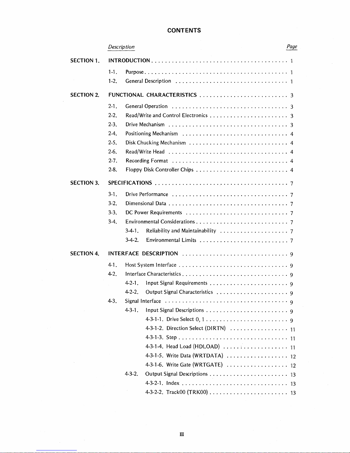
CONTENTS
SECTION 1. INTRODUCTION
1-1 . Purpose....
1-2. General Description
SECTION
2.
FUNCTIONAL CHARACTERISTICS
2-1. GeneraIOperation
2-2. Read/Write and Control Electronics. . . . . . . . . . . . . . . . . . . . .
2-3.
Drive
Mechanism
2-4. Positioning Mechanism
2-5.
Disk
Chucking Mechanism
2-6. Read/Write
2-7. Recording Format
SECTION
2-8. Floppy
3.
SPEC
3-1 . Drive
I FICATIONS . . . . . . . . . . . . . . . . . . . . . . . . . . . . . . . . . . . . . . . 7
Disk
Performance
3-2. Dimensional Data
3-3.
DC
Power Requirements
3-4. Environmental Considerations
3-4-1. Reliability and Maintainability
3-4-2. Environmental Limits
.......................................
. . . . . . . . . . . . . . . . . . . . . . . . . . . . . . . . . . . . . .
................................
..........................
..................................
...................................
...............................
.............................
Head
...................................
..................................
Controller Chips
...........................
..................................
...................................
..............................
...........................
....................
..........................
..
.
.
3
3
3
3
4
4
4
4
4
7
7
7
7
7
7
SECTION
4.
INTERFACE DESCRIPTION
4-1
. Host System Interface . . . . . . . . . . . . . . . . . . . . . . . . . . . . . . . . 9
...............................
4-2. I nterface Characteristics. . . . . . . . . . . . . . . . . . . . . . . . . . . . . . . 9
4-2-1. I nput
4-2-2. Output Signal Characteristics
4-3. Signal Interface
4-3-1. Input Signal Descriptions
4-3-2. Output Signal Descriptions
Signal
Requirements
....................................
4-3-1-1.
Drive
Select 0, 1
4-3-1-2. Direction Select
4-3-1-3.
4-3-1-4.
4-3-1-5. Write Data
4-3-1-6.
4-3-2-1. Index
4-3-2-2.
Step.
. . . . . . . . . . . . . . . . . . . . . . . . . . . . . . .
Head
Load
(H
DLOAD)
(WRTDATA)
Write
Gate (WRTGATE)
...............................
TrackOO
(TRKOO)
.......................
.....................
........................
........................
(DI
RTN)
.................
..... ~ .............
..................
..................
.......................
. . . . . . . . . . . . . . . . . . . . . . .
9
9
9
9
9
9
11
11
11
12
12
13
13
13
III

CONTENTS
SECTION
SECTION
Description
4-3-2-3. Write Protect (WRTPRT)
4-3-2-4. Ready
4-3-2-5. Read Data (RDDATA)
4-4.
5.
CONTROLS AND INDICATIONS .
5-1. Operator Controls and
6.
OPERATION .
6-1
6-2. Operation
6-3. Disk Precautions
6-4. Disk Environmental Limits
Interface Timing
5-1-1.
5-1-2.
5-1-3. Rear
Front
Panel Controls
Front
Panel Indicators
Panel Controls
..........................................
. Disk Description
6-1-1 ~ Disk Preparation and Write Protection
........................................
6-2-1. Disk Eject Mechanism
6-2-2. Disk
6-2-3. Disk Removal
Insertion
..............................
....................................
...........................
Indicators
....................................
...............................
...............................
....................................
.........................
...........................
..........................
...........................
..........................
.............................
..................
...................
...............
Page
14
14
14
15
16
16
16
16
16
17
17
17
18
18
18
18
18
18
SECTION
7.
ELECTRICAL CONNECTORS
7-1. Power Connectors
7-1-1. Frame Ground
7-1-2.
7-1-3.
7-2. Signal Interface
7-2-1. Signal Interface
7-2-2.
DC
DC
Signal
..............................
...................................
...............................
Power
Connector
Power Cable Fabrication
Connector
Inter~ace
.............................
Connector
Cable Fabrication
SECTION 8. MOUNTING AND INSTALLATION
8-1.·
SECTION
Orientation
8-2.
8-3.
9.
ERROR DETECTION AND CORRECTION
Installation....
PCB
Component
.......................................
. . . . . . . . . . . . . . . . . . . . . . . . . . . . . . . . . . .
Locations.
(J2)
.......................
......................
(J
1)
....................
..................
..........................
. . . . . . . . . . . . . . . . . . . . . . . . . . . .
.....................
19
19
19
19
19
20
20
20
21
21
22
23
24
N
SECTION 1
INTRODUCTION
1-1.
PURPOSE
This specification provides the information necessary
to
interface the OA-D30V Micro Floppydisk drive
to
floppy disk controllers, and provides
in
specifications for reference
OEM contracts.
the
technical
1-2. GENERAL
The
SONY Micro Floppydisk drive represents a
technological break through offering extreme
pactness, just 4.0" wide by 2.0" high by 5.1" deep,
and lightweight, just 1.5 Ibs., providing a versatile
data
storage
signer.
SONY·s leadership
niques, perfected
engineers
standard, just
double density capacity
tracks per inch provides nearly double the capacity
of
conventional 5.25" disks.
This disk
it's floppy,
shell provides protection unique
disk. Plus a sliding disk guard
fingerprint and
degrade performance plus a metal centering hub,
allowing positioning
ease and more positive accuracy and over
interchanges with each diskette.
Driven by a
at
a speed
noise ratio while transferring data
500
as fast as conventional
is
a brush
electrical noise and guarantees
Hour.
to
K bits per second
DESCRIPTION
component
in
develop the Micro Floppydisk, a new
3.5".
is
unlike any' you have handled before-
but
not
other
SONY developed direct drive
of
600
less
motor,
for the OEM Systems de-
in
high-density recording tech-
video technology, enabled SONY
Yet
an unformatted, single side,
of
437.5 K bytes
too
floppy. A rigid protective
to
the
to
keep
foreign objects
to
be accomplished with greater
RPM,
providing
in
double density mode, twice
5.25" drives.
it
reduces mechanical and
better
at
As
10,000
in
Micro Floppy-
out
dust, dirt,
that
30,000
signal
a fast rate
drive
Motor On
com-
135
might
motor
to
of
motor
The
SONY proprietary read/write and tunnel erase
is
head developed using video techniques
by a precision stepper
fast access while maintaining positioning accuracy.
And high coercivity media provides high data inergrity.
The
OA-D30V Micro Floppydisk drive
compatible with conventional
Accordingly conventional FDC chips such
Digital FD1791,
Whether your application
word processing, personal computers
you will find the Micro Floppydisk drive offers a
whole new range
The Micro Floppydisk drive offers the following
features.
*
3.5"floppy
NEC
of
disk media with disk guard
* Large capacity
motor
~PD765
possibilities.
..........
* High track density
assembly, providing
8"
floppy disk drives.
can be used.
is
small business systems,
...........
* Long life brushless direct drive
* High transfer rate
......
500Kbps
positioned
is
interface
as
Western
or
any related,
437.5 K bytes
135
TPI
motor
(MFM)
-1-
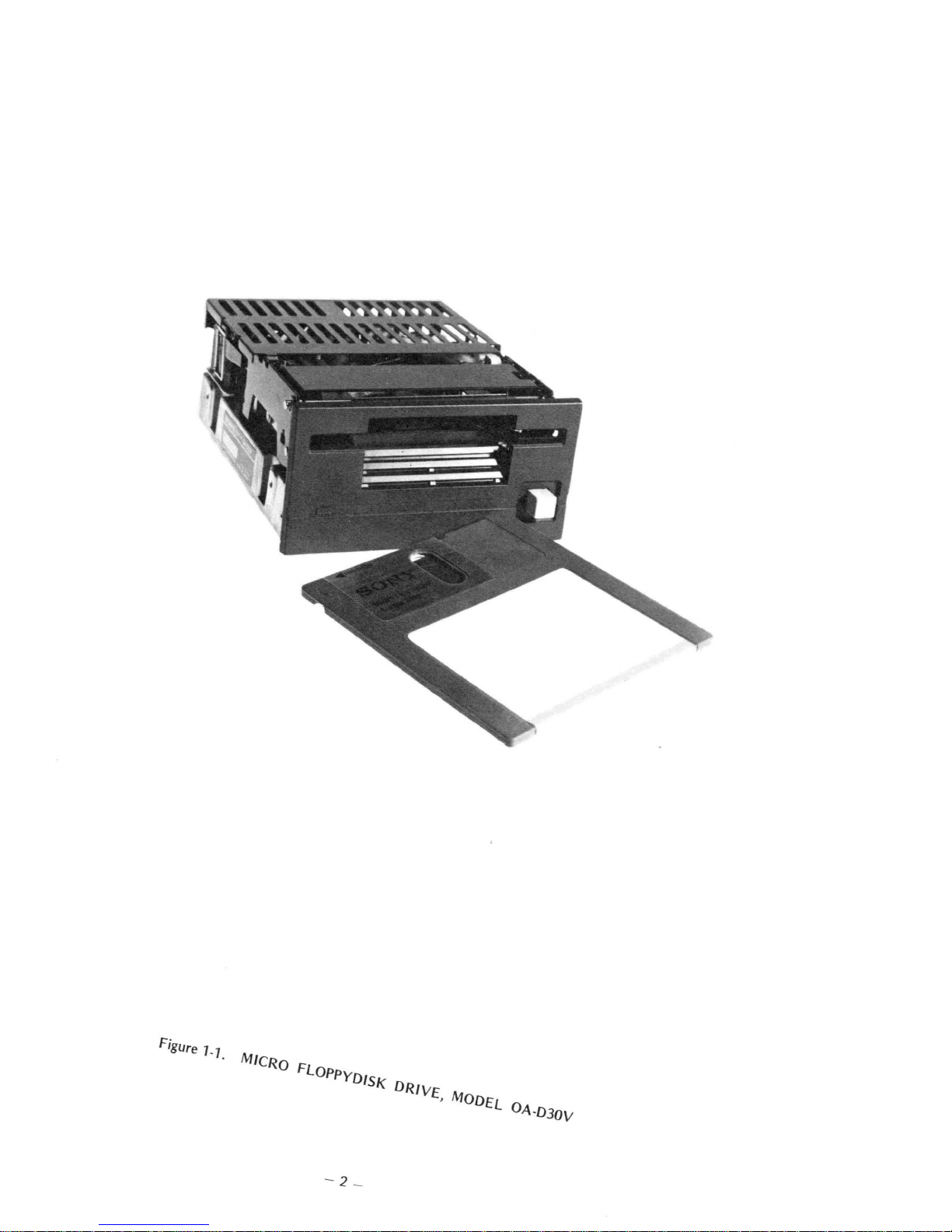
Figure
1-1.
FUNCTIONAL CHARACTERISTICS
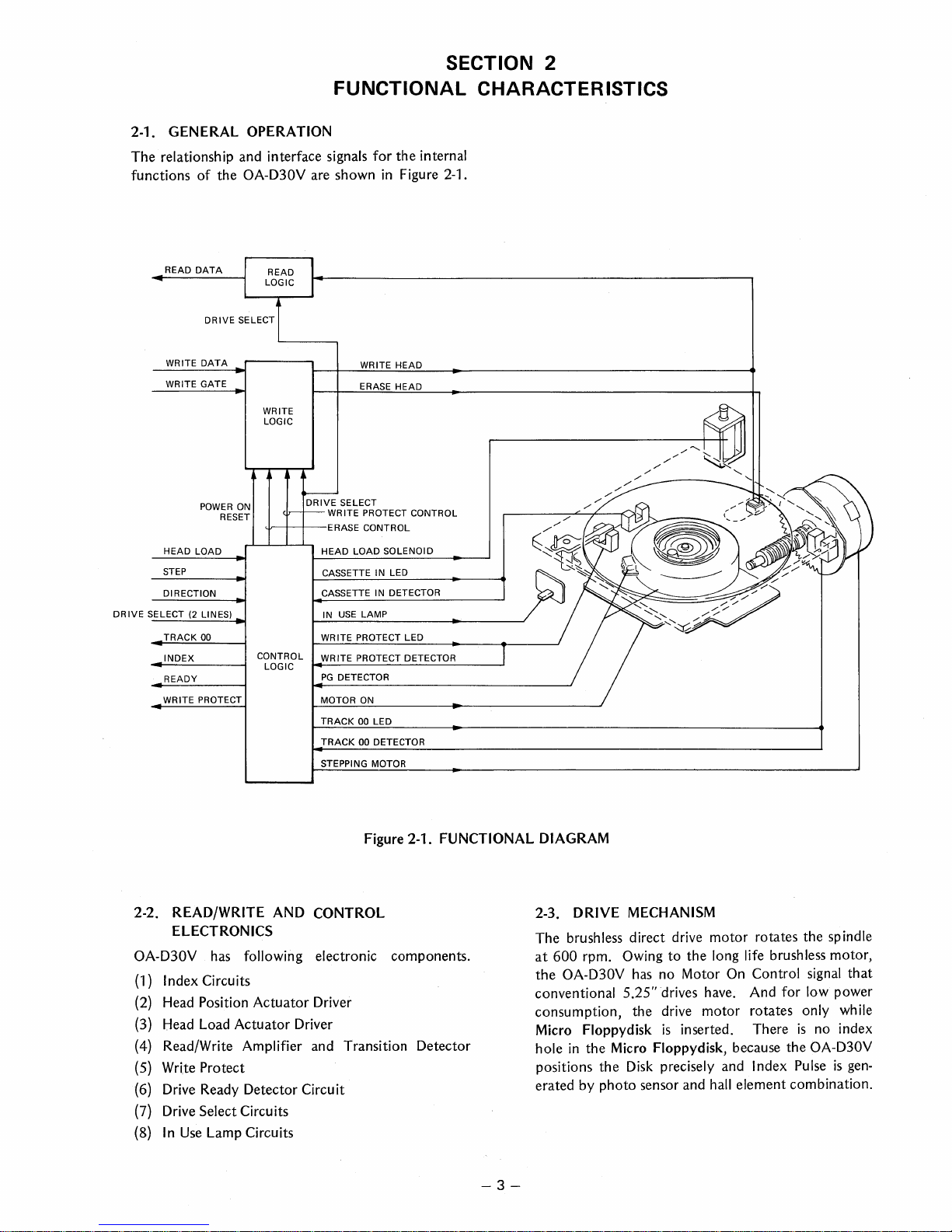
2-1. GENERAL OPERATION
The relationship and interface signals for the internal
functions of the OA-D30V are shown
READ
DATA
DRIVE SELECT
WRITE
DATA
WRITE GATE
WRITE
LOGIC
DRIVE
Ur-+-+--ERASE
CASSETTE IN LED
CASSETTE IN DETECTOR
IN
LOGIC
PG
MOTOR
TRACK 00 LED
TRACK
STEPPING MOTOR
WRITE PROTECT CONTROL
DRIVE
POWER
ON
RESET
HEAD LOAD HEAD LOAD SOLENOID
STEP
DIRECTION
SELECT
(2
LINES)
TRACK 00 WRITE PROTECT LED
INDEX
READY
WRITE PROTECT
CONTROL WRITE PROTECT DETECTOR
WRITE
ERASE HEAD
SELECT
CONTROL
USE
LAMP
DETECTOR
ON
00 DETECTOR
in
Figure 2-1.
HEAD
SECTION 2
2-2. READ/WRITE
AND
CONTROL
ELECTRONICS
has
OA-D30V
(1)
Index Circuits
(2)
Head Position Actuator Driver
(3)
Head Load Actuator Driver
(4)
Read/Write Amplifier and Transition Detector
(5)
Write Protect
(6)
Drive Ready Detector Circuit
(7)
Drive Select Circuits
(8)
In
Use
following electronic components.
Lamp Circuits
Figure 2-1. FUNCTIONAL DIAGRAM
2-3. DRIVE
The brushless direct drive motor rotates the
at
600 rpm. Owing to the long life brush
OA-D30V
the
conventional 5.25" drives have. And for low power
consumption, the drive motor rotates
Floppydisk
Micro
hole
in
the Micro Floppydisk, because the OA-D30V
positions the
erated by photo sensor and
-3-
MECHANISM
has
no Motor
is
Disk
precisely and Index Pulse
On
inserted. There
hall
element combination.
Control
sp
indle
less
motor,
signal
that
only while
is
no
index
is
gen-
2-4. POSITIONING MECHANISM
In
order
to
achieve high accuracy
the
head
is
positioned
And a
is
to
rotates
in
moves
'steppingmotor
controlled through the posicast control method
do
the best performance.
the
lead screw clockwise
45°
increments. A
the
read/write head
+5 V and +12 V Power
Actuator
positions
And if the head
command
2-5.
is
rejected.
DISK CHUCKING MECHANISM
by
45°
the
read/write head
is
positioned
is
A new medium utilizes a centering metal
in
track positioning,
a needle screw mechanism.
(Head Position Actuator)
The
stepping
or
counterclockwise
rotation
one
on,
of
the lead screw
track position. When
the
Head Positioning
at
TRACKOO.
at
TRACK69, STEP
hub
maintains excellent Track positioning accuracy
out
causing eccentricity
or
chucking wear. (See
Figure 2-2.)
motor
IN
which
with-
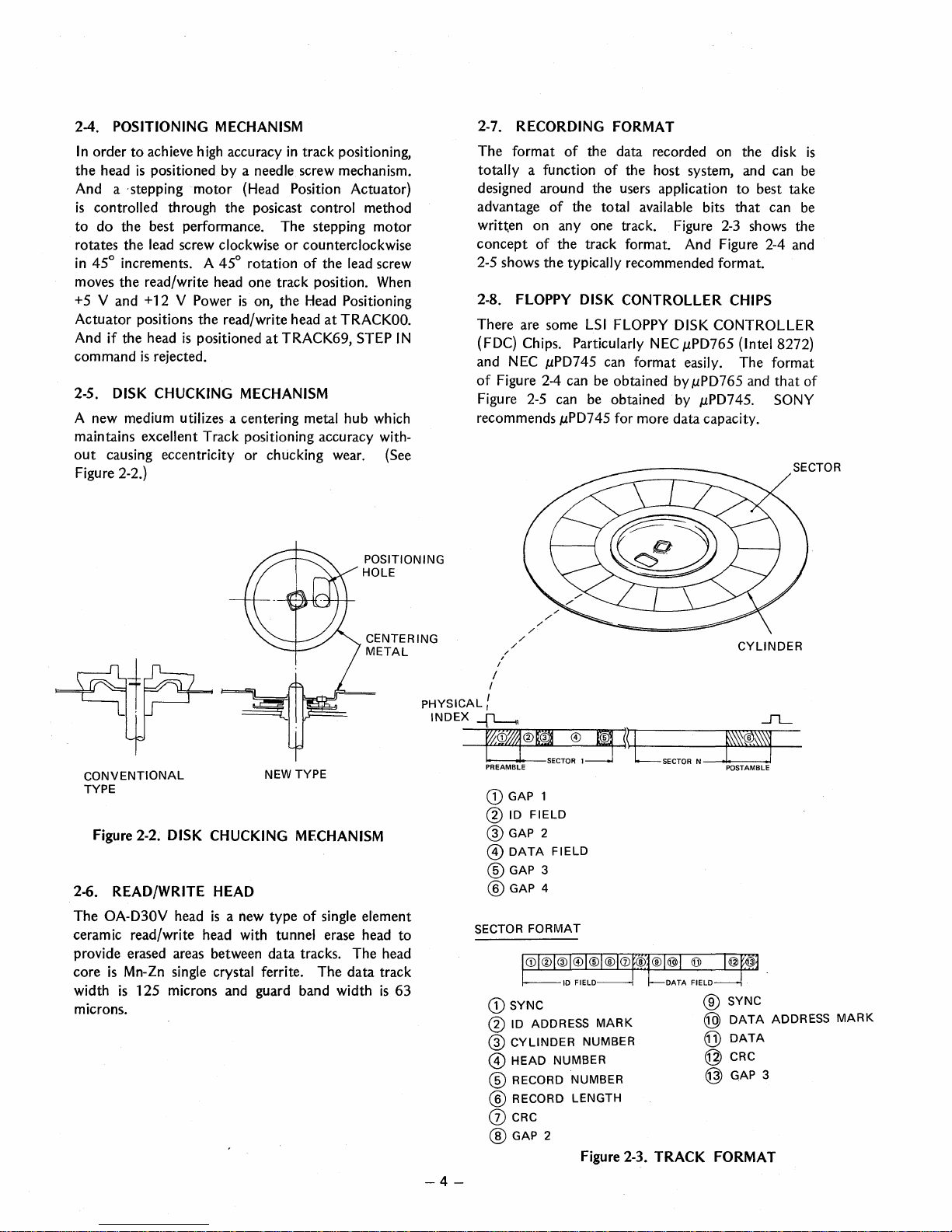
RECORDING FORMAT
2-7.
The
format
totally
of
a function
the data recorded on
of
the
host system, and can be
designed around the users application
of
advantage
written
concept
2-5 shows
2-8.
FLOPPY DISK CONTROLLER CHIPS
There are some
(FDC) Chips. Particularly NEC
and NEC
of
Figure 2-4 can be obtained by
Figure 2-5 can be obtained by
recommends
the total available bits
on
anyone
of
the track format. And Figure 2-4 and
the
typically recommended format.
track. Figure
LSI
FLOPPY DISK CONTROLLER
J,LPD765
J,LPD745
can format easily.
J,LPD765
J,LPD745.
J,LPD745
for more
data
capacity.
the
to
best take
that
can be
2-3
shows the
(Intel 8272)
The
and
disk
format
that
of
SONY
SECTOR
is
CONVENTIONAL
TYPE
NEW TYPE
Figure 2-2. DISK CHUCKING MECHANISM
2-6. READ/WRITE HEAD
The
OA-D30V head
is a !'lew
type
of
single element
ceramic read/write head with tunnel erase head
provide erased areas between
core
is
Mn-Zn single crystal ferrite.
is
125
width
microns and guard band width
data
tracks.
The
The
data
head
track
is
microns.
PHYSICAL:
to
63
-4-
/
/
/
/
INDEX~,
~W~®(@J
L -J
PREAMBLE
CD
@ 10
@GAP
@
® GAP 3
®GAP
SECTOR
CD
@ 10 ADDRESS
@
@
® RECORD
® RECORD
(j) CRC
® GAP 2
/'
./
/
/
/
./
:ECTOR
GAP
1
FIELD
2
DATA
FIELD
4
FORMAT
SYNC
CYLINDER
HEAD
NUMBER
CYLINDER
®.-m
~~f-t--L_--f~I.U.l.U.>.~~~-
1=:J
NUMBER
MARK
LSECTOR
N
®
@
@
L-i
POSTAMBLE
SYNC
DATA
DATA
@ CRC
NUMBER
LENGTH
Figure 2-3. TRACK FORMAT
@ GAP 3
~
ADDRESS
MARK

0"1
I
l
I
INDEX
~~---------------------------------~1r-----1L-
SECTOR 1
SECTOR
2--
ID
FIELD
DATA
FIELD
GAP31
GAP4b
GAP
INDEX
GAP
IDADD
C
HI+
ICjC
GAP
DATA
CRC
GAP
SYNC
SYNC
SYNC
DATA
1112
SYNC
GAP
4b
4a
MARK
1
MARK
1 2
2
MARK
3
SINGLE
l
BYTE
(10)
40
6
1
26
6
1
4
2
11
6
1
2
6
DENSITY
1
DATA
(16)
FF
00
FC
FF
00
FE
**
**
FF 00
FBIF8
DATA
**
FF
00
FF
-
DOUBLE
l
BYTE
(10)
80
12
3
1 1
50
12
3
1 1
4
2
22 12
31
1
2
12
I
DENSITY
1
DATA
(16)
4E
00
C21
FC
4E
00
A1
J FE
**
**
4E
00
A11~:
DATA
**
4E
00
4E
,
PREAMBLE
SECTOR
~~\..~
~OS"(.p.:
Gp.~'?>
GAP4
(MIN.) FM GAP 4
>
11
MFM
GAP4
>
2
20
128 73 188
27
232 15
SINGLE
256 73
331
42 73 9
DENSITY
(10)
512 73 603 58
640
4
256
146
372
54
524 15
DOUBLE
512 146
658
84
182 9
DENSITY (10)
1024
146
1202
116
1296
4
DATA
GAP3
GAP4
SECTORI
TRACK
SINGLE DENSITY DOUBLE DENSITY
DATA
CLOCK
DATA
CLOCK
INDEX
ADDRESS
MARK
FC
D7
FC
01
ID
ADDRESS
MARK
FE
C7
FE
00
DATA
ADDRESS
MARK
FB
C7
FB
00
DELETED
DATA
ADDRESS
MARK
F8
C7
F8
03
GAP
FF FF
4E
10
SYNC
00
FF
00
FF
Figure 2-4. pPD765 IBM TYPE STANDARD FORMAT
 Loading...