

Sony NXL-IP55 Operation Manual

IP LIVE PRODUCTION UNIT
NXL-IP55
OPERATION MANUAL [English]
1st Edition (Revised 1)

Table of Contents
Overview ......................................................3
Features......................................................... 3
Transmittable Signals ................................... 3
Supported Networks ..................................... 3
System Configuration Examples ...............4
3-Camera System.......................................... 4
2-Camera System.......................................... 5
1-Camera System.......................................... 6
System Using Cameras Unable to Output
SDI Audio Signals............................... 7
Configuration Example when Using
Intercom .............................................. 8
Tally Signal Usage Example ........................ 8
GPIO Signal Usage Example........................ 8
Names and Functions of Parts...................9
Front.............................................................. 9
Rear............................................................... 9
Settings ......................................................11
Configuring Settings................................... 11
Input/Output Phases for HD-SDI Signals... 15
Settings Examples....................................... 17
Operation ...................................................20
Starting Video Transmission ...................... 20
Outputting Color Bars and Tone Signal ..... 20
Displaying the Status .................................. 20
Menus .........................................................21
Menu Structure ........................................... 21
[Status] Page ............................................... 21
[Operator] Page........................................... 24
[I/O] Page.................................................... 25
[Structure] Page .......................................... 29
[Network] Page........................................... 31
[Others] Page .............................................. 32
Specifications............................................34
External Interfaces ....................................35
Notice on GNU GPL/LGPL Licensed
Software ..............................................36
Table of Contents
2

Overview
intercom signals embedded on HD-SDI signals (up to
eight channels in the same direction).
Notes
Features
The NXL-IP55 IP Live Production Unit is an IP
transmission device that allows upstream and
downstream transmission of HD video signals, audio
signals, and various control signals with low latency of
less than one field (excluding network delays). Using the
unit allows you to configure a live production system over
a network.
Network synchronization
Devices can be synchronized via a network. Low-latency
video transmission is made possible during live
production by eliminating the need for synchronization
via a frame synchronizer.
Various transmission signals
Up to four video channels are available for transmission
with up to three in the same direction. Ten audio channels
(five pairs) are available for transmission with eight in the
same direction. Eight GPIO channels, six tally channels,
and one channel for a synchronization signal are also
available.
Note
The content of this document applies to firmware version
V1.10.
NXL-IP55 units with different firmware version cannot
be connected together. You can check the firmware
version in [Device Information] on the [Status] page in
the Web menu.
If using an NXL-IP55 unit with a different firmware
version, contact your store or point of purchase.
• HD-SDI embedded audio can be transmitted on Ch1 to
Ch2 or Ch1 to Ch4. The audio will not be transmitted
on Ch5 and above.
Metadata attached to HD-SDI signals cannot be
transmitted.
• When transferring Dual Link SDI, audio signals can be
embedded in Link-A only.
Tally signals
Three channels each are available for R tally signals and
G tally signals.
However, the transmission direction for all channels is the
same.
GPIO
Eight channels are available.
The transmission direction can be switched by using four
channels as one group.
Supported Networks
Use this unit in a network that meets the following
specifications. Check whether the network you want to
use fulfills these requirements by performing a network
test in the web menu before use.
Note
The network test only displays the status of the area that
can be detected at the moment the test is executed. It does
not guarantee the quality of the network or the operation
of this unit.
Transmittable Signals
Video signals
1080/50i, 1080/59.94i, 720/50P, 720/59.94P,
1080/25PsF, 1080/29.97PsF
Can transfer up to four channels of HD SDI signals,
with up to three in the same direction.
1080/50P, 1080/59.94P
Can transfer total of two channels using Dual Link
SDI, with one in each direction.
Note
Signals with different formats cannot be transferred at the
same time.
Audio signals
Up to five pairs of two channels (48 kHz/24 bit) are
available for audio signals, analog audio signals, and
Network connected to the MAIN connector
This network connects to the unit’s MAIN connector and
transmits video signals and control signals.
The requirements for this network are as follows.
• The network is a secure LAN independent from other
systems and networks. It cannot be used as a WAN or
Internet line.
• Use a Layer 2 switch with 5 or less levels. Routers
cannot be used.
• Interface: 1000BASE-T
• MTU: 1500 bytes or higher, no fragments
• Latency: 10 ms or less without fluctuation (one way)
• Bandwidth: 600 Mbps or more maintained
Network connected to the CONTROL connector
This network connects to the unit’s CONTROL connector
and connects the computer used to configure this unit.
• Interface: 100BASE-TX
Overview
3
System Configuration Examples
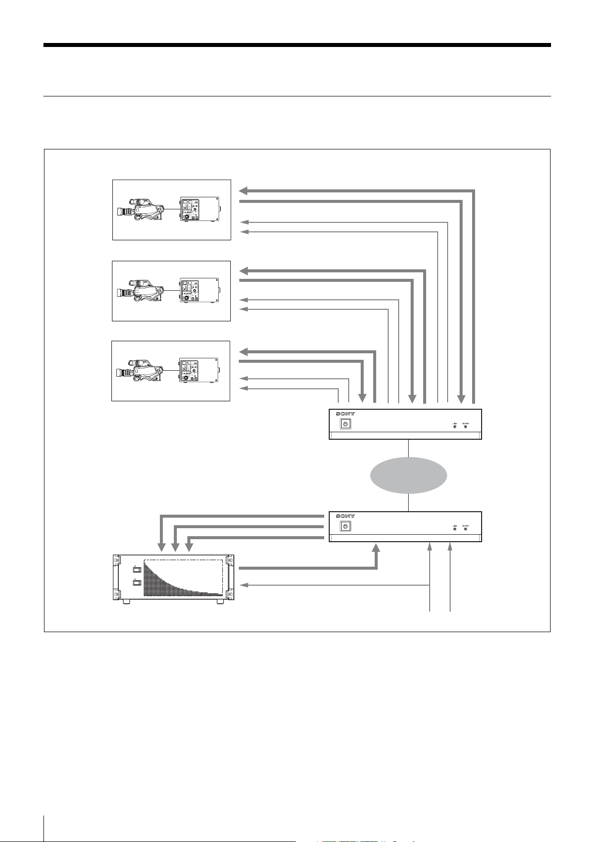
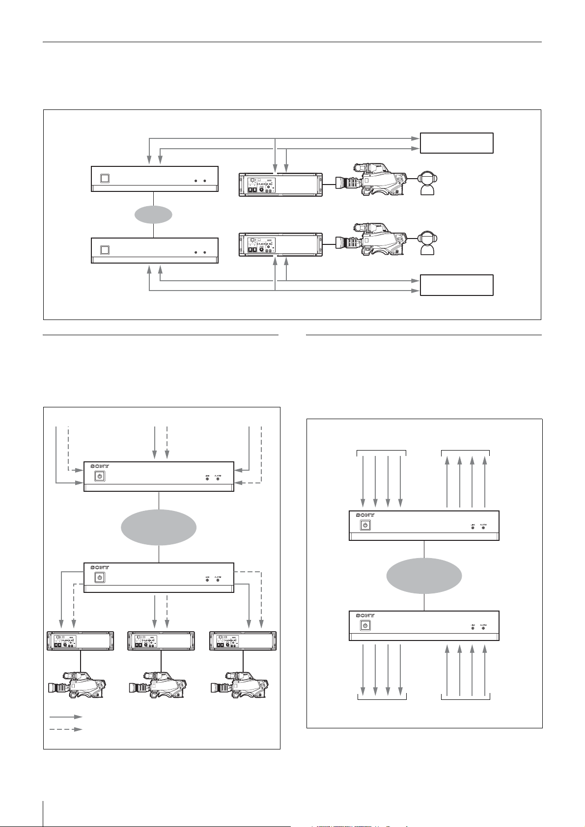
3-Camera System
The main line signals from three cameras can be transmitted. One channel is available for transmitting return signals.
Camera 1
Return signal (HD-SDI)
Main line signal 1 (HD-SDI)
Tally signal
Synchronization signal
Camera 2
Return signal (HD-SDI)
Main line signal 2 (HD-SDI)
Tally signal
Synchronization signal
Camera 3
Return signal (HD-SDI)
Main line signals 1 to 3 (HD-SDI)
Video router
Main line signal 3 (HD-SDI)
Tally signal
Synchronization signal
NXL-IP55
Network
NXL-IP55
Return signal (HD-SDI)
Synchronization signal Tally signal
System Configuration Examples
4
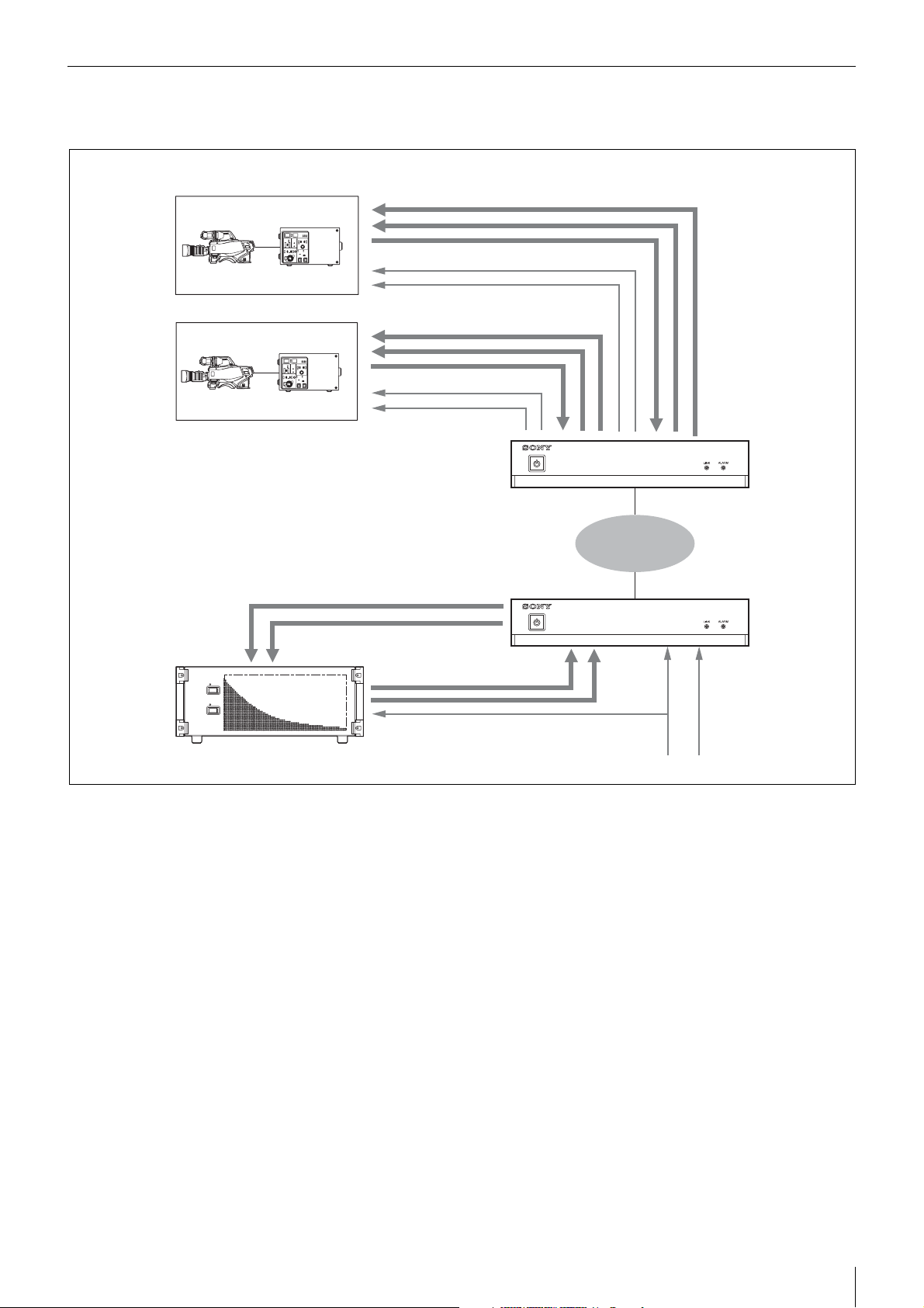
2-Camera System
The main line signals from two cameras can be transmitted. Two channels are available for transmitting return signals.
Camera 1
Camera 2
Return signals 1 and 2 (HD-SDI)
Main line signal 1 (HD-SDI)
Tally signal
Synchronization signal
Return signals 1 and 2 (HD-SDI)
Main line signal 2 (HD-SDI)
Tally signal
Synchronization signal
Main line signals 1 and 2 (HD-SDI)
NXL-IP55
Network
NXL-IP55
Video router
Return signals 1 and 2 (HD-SDI)
Synchronization signal Tally signal
System Configuration Examples
5
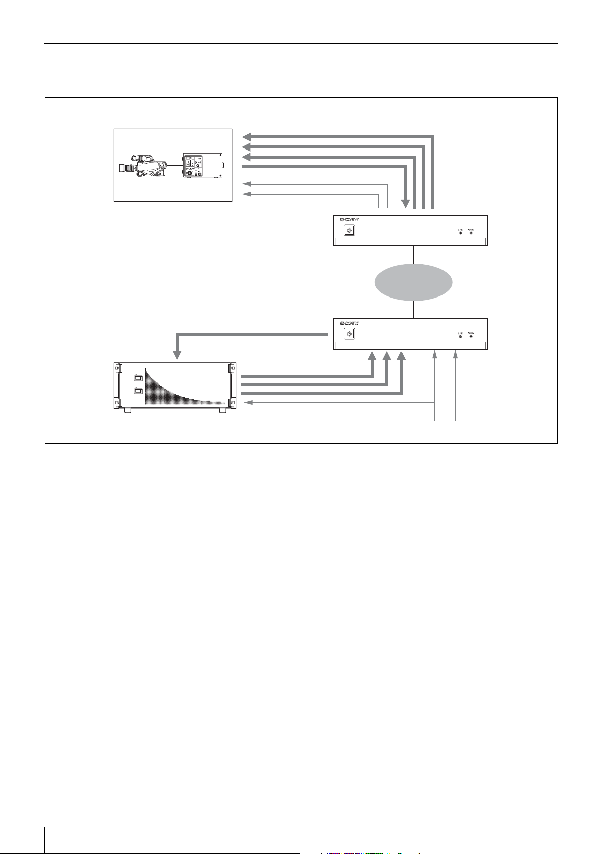
1-Camera System
The main line signal from one camera can be transmitted. Three channels are available for transmitting return signals.
Camera 1
Return signals 1 to 3 (HD-SDI)
Main line signal 1 (HD-SDI)
Tally signal
Synchronization signal
Main line signal (HD-SDI)
Return signals 1 to 3 (HD-SDI)
NXL-IP55
Network
NXL-IP55
Video router
Synchronization signal Tally signal
System Configuration Examples
6
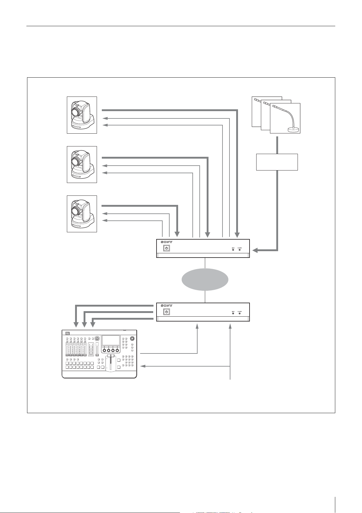
System Using Cameras Unable to Output SDI Audio Signals
When using cameras that cannot embed audio signals onto HD-SDI signals, you can input analog audio signals via a
separate channel and map them onto HD-SDI signals for transmission. As audio input levels are at line level, an external
microphone amplifier is necessary when using a microphone.
Camera 1
Camera 2
Camera 3
Main line signal 1 (HD-SDI)
Tally signal
Synchronization signal
Main line signal 2 (HD-SDI)
Tally signal
Synchronization signal
Main line signal 3 (HD-SDI)
Tally signal
Synchronization signal
NXL-IP55
Microphone
Microphone
amplifier
Analog
audio
signals
Main line signals 1 to 3 (HD-SDI)
Switcher
1) Audio signal inputs are embedded.
1)
NXL-IP55
Network
Tally signal
Synchronization signal
System Configuration Examples
7
Configuration Example when Using Intercom
Connecting an intercom system to this unit’s AUDIO/INTERCOM connector enables intercom transmission and allows
you to combine two intercom systems.
PROD
Intercom system
ENG
NXL-IP55
Network
NXL-IP55
Camera control unit Camera
Tally Signal Usage Example
Two channels per camera for three cameras are available
for transmitting tally signals via the unit’s TALLY/GPIO
connector.
PROD
Intercom system
ENG
GPIO Signal Usage Example
Two groups of four GPIO (General Purpose Input/
Output) signals can be transmitted via the unit’s TALLY/
GPIO connector. The transmission direction can be
changed for each group.
GPIO group 1
GPIO group 2
NXL-IP55
NXL-IP55
: Red tally
: Green tally
Network
NXL-IP55
NXL-IP55
GPIO group 1
Network
GPIO group 2
System Configuration Examples
8
Names and Functions of Parts
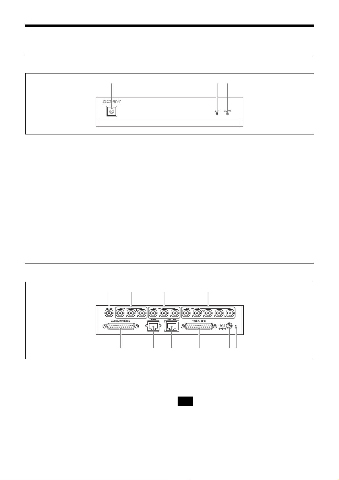
Front
123
a Power switch / indicator
This is the power switch. The indicator lights when the
unit is turned on. Stable output of video signals may take
some time after the unit is turned on. The LINK indicator
will blink or light blue and video signals will not be
output until proper output is established.
To turn the unit off, press and hold the switch for at least
2 seconds.
b LINK indicator
Indicates the connection status.
Lit green: Connected to the partner device.
Blinking green: Connected to the partner device, but
there is a problem with the status of the network
connected to the MAIN connector.
Rear
12 3 4
Blinking blue: Connection is being established. As the
connection process progresses, the indicator blinks
more rapidly.
Lit blue: Connection has been established, and the unit
is waiting for signal output to stabilize. Video
signals are not output during this time.
Off: Not connected to the LAN.
c ALARM indicator
Lights red when an error is detected.
Check the [Status] page of the web menu for details on the
error.
The indicator blinking red indicates an internal error. If
restarting the unit does not resolve the problem, consult
your Sony service representative.
567890
a REF IN connector
Inputs the synchronization signal.
Input is not necessary when using the SDI signal as a
synchronization signal, or when the synchronization
setting is set to [Follower] and a frame synchronizer is not
used.
b REF OUT connectors (1/2/3)
Output synchronization signals. The same signal is output
from each of these three ports.
Notes
• The subcarrier phase during black burst signal output is
not guaranteed.
• The accuracy of frequencies when synchronization is
not applied to unit is not guaranteed.
Names and Functions of Parts
9
c HD SDI IN connectors (1/2/3)
Input SDI signals for transmission.
When using an SDI signal as the synchronization signal,
input it to HD SDI IN connector 1.
d HD SDI OUT connectors (1/2/3/4/M)
Output transmitted SDI signals or SDI signals that were
input to this unit.
Monitor signals are output from HD SDI OUT connector
M. Text information can be superimposed onto outputs
from this connector. Monitor output can be selected using
the web menu.
Note
When outputting signals that are input to this unit, a delay
of 1 or 2 lines may occur.
e AUDIO/INTERCOM connector
Connects to analog audio equipment and intercom
systems.
The AUDIO/INTERCOM and TALLY/GPIO connectors
are both 25-pin D-sub connectors. Be sure to check the
labels to avoid incorrect connections.
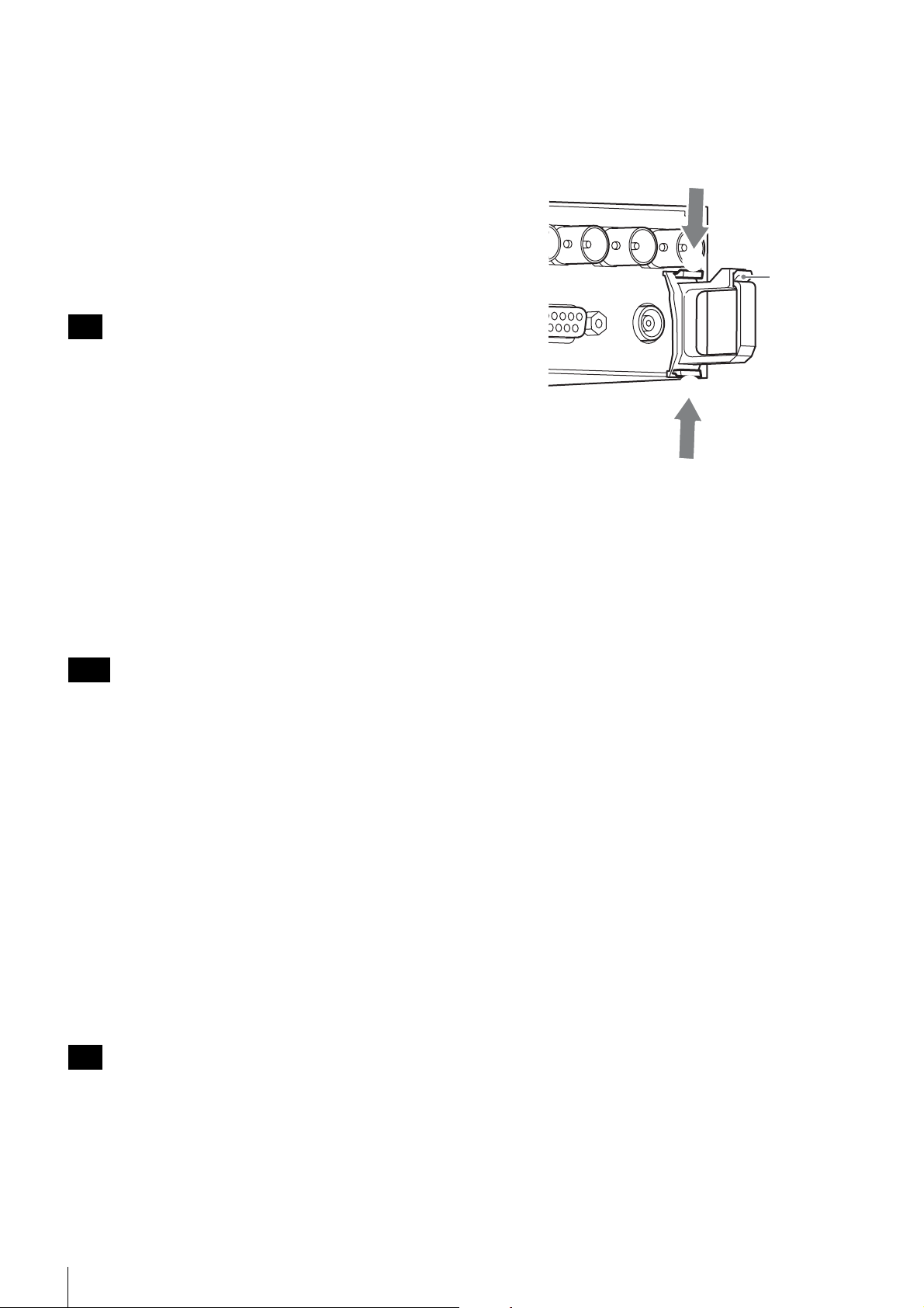
j Clamp attachment point
Attach the supplied clamp here. Open the tab (1) to pass
the power cable through the clamp.
To remove the clamp, push the tabs (2) in the direction
of the arrows.
2
1
2
f MAIN connector
This is a network connector that supports 1000BASE-T.
Video signals and control signals are transmitted between
multiple units of this device via a gigabit network.
This single connector has two IP addresses.
Notes
• Always connect to a 1000BASE-T network. The unit
will not operate with other network types.
• Connect the unit using a CAT5e LAN cable or above.
g CONTROL connector
This is a network connector that supports 100BASE-TX.
Connect a computer to this connector, and use it to
configure settings for this unit via the web menu. If you
do not need to display or operate the web menu, this
connection is not necessary.
Video signals cannot be transmitted from this connector.
h TALLY/GPIO connector
Inputs/outputs tally signals or GPIO signals.
i DC IN connector
Connects to the supplied AC adapter.
Note
For safety, use only the AC adapter supplied with this
unit.
Names and Functions of Parts
10
Settings
Configuring Settings
Perform the following to configure settings.
1. Connecting the computer (required)
2. Changing the password
3. Network settings (required)
4. Format settings (required)
5. Video transmission settings (required)
6. Synchronization settings (required)
7. Transmission rate settings (required)
8. Audio signal settings (required)
9. Tally signal settings (required)
10. GPIO settings (required)
11. Date and time settings
12. Changing the web menu title
13. Backing up and restoring settings
14. Importing and exporting settings
15. Verifying settings
16. Verifying the network environment
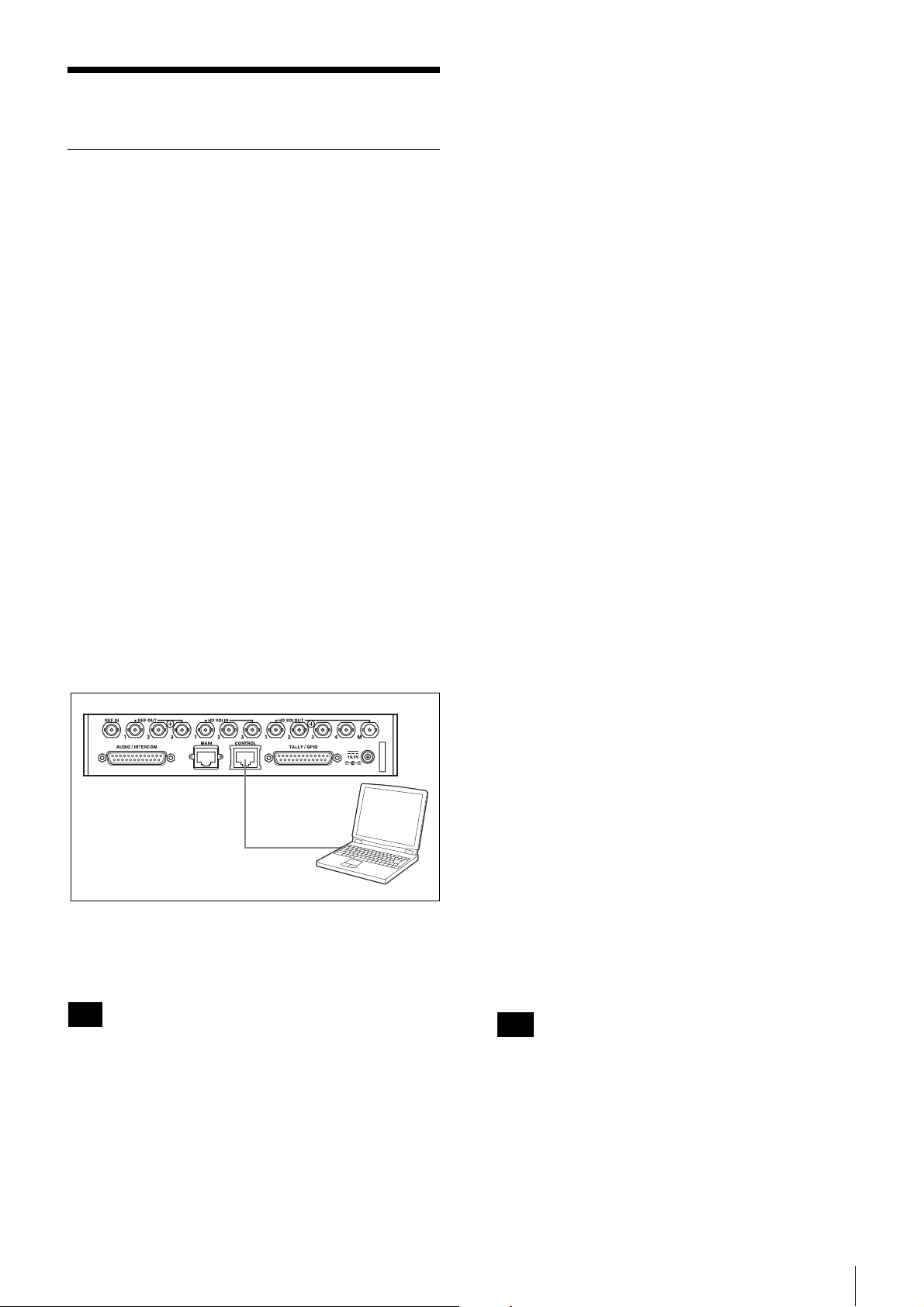
1. Connecting the computer
A computer can be connected to this unit’s CONTROL
connector using a LAN cable (either straight or cross).
LAN cable
Open a web browser on the computer, and enter “http://
192.168.0.3” (or an amended IP address) in the address
field.
The web menu used to configure this unit appears.
Subnet mask: 255.255.255.0
Default gateway: 192.168.0.253
The network settings can be checked via the [Status] page
of the web menu or via the text information superimposed
on the monitor output.
2. Changing the password
User names and passwords can be changed on the
[Others] page.
Password entry is required to display pages other than the
[Status] page and [Operator] page. The factory default
user name and password are as follows.
User name: Users
Password: NXL-IP55
3. Network settings
The network settings are configured on the [Network]
page.
Settings must be configured for the MAIN connector
network, which transmits the main line signal, and the
CONTROL connector network, which connects to the
computer used to setup this unit.
MAIN connector settings
These are configured under [Main Port Configuration] on
the [Network] page.
Although it is one connector, it has two IP addresses –
Main 1 and Main 2. When you configure the IP address
for Main 1, a sequential IP address is configured for Main
2 automatically. Make sure that the IP addresses do not
overlap with other devices.
• [Host IP Address (1/2)]: Enter the IP address for Main
1.
• [Host IP Address (2/2)]: This is configured
automatically when you enter an address for [Host IP
Address (1/2)]. This cannot be modified.
• [Subnet Mask]: This setting is the same for Main 1 and
Main 2.
• [Destination IP Address (1/2)]: Enter the Main 1 IP
address of the other connected NXL-IP55 unit (i.e., the
connection destination).
• [Destination IP Address (2/2)]: This is configured
automatically when you enter an address for
[Destination IP Address (1/2)]. This cannot be
modified.
• [Speed]: Displays the connection speed.
• [Stream Mode]: Set to “Multicast” if using the PC
application software (optional), or set to “Unicast”
otherwise.
Note
When configuring settings, be sure to click the [Apply]
button after configuring settings in each web menu page.
If you switch to a different page or close the web browser
without clicking the [Apply] button, the settings will not
be applied.
The factory settings for this unit’s CONTROL connector
are as follows.
IP address: 192.168.0.3
Note
In Multicast mode, multicast packets are sent from the
switch to all ports, which may affect communication on
other ports. In order to avoid this, use the IGMP
snooping function and IGMP query function of the
switch to monitor traffic, or take other measures such as
segmenting the network connected to the MAIN
connector and the network with the CONTROL
connector using VLANs.
Settings
11

• [Multicast Address]: If “Multicast” is configured in
[Stream Mode], set the IP addresses. Six addresses are
required. Setting one address automatically sets the
remaining five addresses in sequence. Set
corresponding addresses on the connected devices. If
“Unicast” is configured in [Stream Mode], no entry is
required.
• [Register IP Address]: If a computer running the PC
application software (optional) is connected, enter the
IP address of the computer. Set [Stream Mode] to
“Multicast” to configure this parameter. The required
address is the IP address of the computer connected to
the same network segment as the MAIN connector of
the unit. IP addresses for up to eight computers can be
configured.
CONTROL connector settings
These are configured under [Control Port Configuration]
on the [Network] page.
• [DHCP]: Select whether to use DHCP. When using
DHCP, the IP address allocated to the unit can be
monitored using character information superimposed
on the monitor output.
• [IP Address], [Subnet Mask], [Default Gateway]:
Configure these if [DHCP] is disabled.
[2Transmit 2Receive] is specified, specify [2Transmit
2Receive] again for the partner device.
If “1080/59.94P (Dual Link)” or “1080/50P (Dual
Link)” is selected in [Video Format], [Structure] is
fixed to “2Transmit 2Receive” and Dual Link 1
operates in bidirectional transfer mode. Connect the
Link-A input to HD SDI IN connector 1, and the LinkB input to HD SDI IN connector 2. The HD SDI IN 3
connector is disabled. Connectors HD SDI OUT 1 and
2 are grouped, as are connectors HD SDI OUT 3 and 4.
Link-A is output from connectors HD SDI OUT 1 and
3, and Link-B is output from connectors HD SDI OUT
2 and 4.
6. Synchronization settings
Configure synchronization between transmission
devices.
Selection of whether a device is the Leader or Follower in
regards to the synchronization signal is performed under
[Network GenLock] on the [Structure] page.
Select [Leader] for the transmitting device, and
[Follower] for the subordinate device. Transmission is
not possible between two Leader devices or two Follower
devices.
Note
When specifying IP addresses for the MAIN connector
and the CONTROL connector, do not use multicast
addresses, broadcast addresses, or other special reserved
addresses.
4. Format settings
Select the image format for transfers under [Video
Format] in the [Structure] page.
5. Video transmission settings
The direction of the video’s main line signal and the
number of transceiver channels are configured under
[Transmission Settings] on the [Structure] page.
• [Main Video Direction]: Select [Transmitter] for the
camera transmitting main line signals, and [Receiver]
for the video router receiving the signals.
On the Receiver side, the phases of the input SDI
signals and the SDI signals sent from the Transmitter
will match. On the Transmitter side, the phases of the
input SDI signals and the SDI signals sent from the
Receiver will not match (when [Frame Synchronizer] is
[OFF]).
Selecting the [Transmitter] and [Receiver] establishes a
pair. Communication will not be possible if both sides
are set identically.
• [Structure]: Configure the number of transmitter/
receiver channels. The number of channels for the
Transmitter and the Receiver should be inverted.
For example, in a 3-camera system with one return
channel, specify [3Transmit 1Receive] for the cameras
and [1Transmit 3Receive] for the video router.
Alternatively, if [3Transmit 1Receive] is specified,
specify [1Transmit 3Receive] for the partner device. If
Next, select the synchronization signal to be input under
[Reference in] on the [I/O] page.
• [Source]: Select either the input signal from the REF IN
connector or from HD SDI IN connector 1 to be the
synchronization signal.
• [Format]: When [Reference in] is selected for [Source],
select [HD] (HD 3-value sync) or [SD] (SD sync).
• [V Phase]: Enter this unit’s vertical phase for the input
synchronization signal.
The input signal must be in phase with this unit.
However, an unsynchronized signal can be input if there
is only one channel. In such cases, use the frame
synchronizer. For details, see “Settings when using a
frame synchronizer” on page 18.
The synchronization signal to be output from the REF
OUT connector is configured under [Reference out] on
the [I/O] page.
• [Format]: Select [HD] (HD 3-value sync), [SD (BB)],
or [SD (SYNC)] (SD sync) as the synchronization
signal to be output.
• [V Phase]: Enter this unit’s vertical phase for the output
synchronization signal.
Note
Configure the [Reference in] and [Reference out] settings
for both the NXL-IP55 Leader and Follower units.
7. Transmission rate settings
The transmission rate for video signals is configured
under [Video Code Rate] on the [Structure] page.
Configure identical settings for both the NXL-IP55
sender and receiver units. Configuring a high rate enables
12
Settings
 Loading...