

Sony NEX-FS700, NEX-FS700K, NEX-FS700EK, NEX-FS700J, NEX-FS700JK Service Manual
...
SERVICE MANUAL
NEX-FS700/FS700K/FS700C/FS700CK/FS700E/FS700EK/FS700J/FS700JK/FS700R/FS700RH/FS700U/FS700UK
Revision History
Published by Sony Techno Create Corporation
Sony Corporation
SERVICE NOTE (Check the following note before the service.)
983475411.pdf
Ver. 1.0 2013.09
INTERCHANGEABLE LENS DIGITAL HD VIDEO CAMERA RECORDER
The components identified by mark
0 or dotted line with mark 0 are
critical for safety.
Replace only with part number
specified.
Les composants identifiés par une
marque 0 sont critiques pour la
sécurité.
Ne les remplacer que par une
pièce portant le numéro spécifié.
9-834-754-11
US Model
Canadian Model
AEP Model
E Model
Chinese Model
Japanese Model
Ver. Date History Contents
S.M. Rev.
issued
1.0 2013.09 Official Release — —
2013I08-1
© 2013.09
– ENGLISH –
1-1. POWER SUPPLY DURING REPAIRS
1-2.
PRECAUTION ON REPLACING THE VC-650 BOARD
1-3. ADDITION OF DESTINATION DATA FILE
1-4. PRECAUTION ON REPLACING THE MB N PLATE AND NDF UNIT
1-5. SELF-DIAGNOSIS FUNCTION
1-6. METHOD OF COPING WITH LENS ERROR
– JAPANESE –
1-1.
修理時の電源供給について
1-2.VC-650
基板交換時の注意
1-3.Destination Data
ファイルの追加について
1-4.MB N
プレートと
NDF
ユニット交換時の注意
1-5.
自己診断機能
1-6.
レンズエラーの対処方法
Note: This manual contains information of the NEX-FS700/FS700K/FS700C/FS700CK/FS700E/FS700EK/FS700J/FS700JK/FS700U/FS700UK Service Manual
(9-834-674-[][]) and additional NEX-FS700R/FS700RH information.
Note:
このマニュアルはNEX-FS700/FS700K/F S700C/FS700CK/FS700E/F S700EK/FS700J/FS700JK/FS700U/F S700UKのサービスマニュアル
(9-834-674-[][])にNEX-FS700R/FS700RHの情報を追加したものです。
[About the service of this model]
NEX-FS700K/FS700CK/FS700EK/FS700JK/FS700RH/FS700UK are commodity that packed the Interchangeable Lens Digital HD Video Camera
Recorder and Interchangeable Lenses. Refer to each following service manual the Interchangeable Lens kit, when you repair.
Model Lens Service Manual of Lens
NEX-FS700K/FS700CK/FS700EK/FS700JK/FS700UK SEL18200 (E 18-200mm F3.5-6.3 OSS) 9-834-507-1[]
NEX-FS700RH SELP18200 (E PZ 18-200mm F3.5-6.3 OSS) 9-834-703-1[]
Photo: NEX-FS700K
NEX-FS700/FS700K/FS700C/FS700CK/FS700E/FS700EK/
FS700J/FS700JK/FS700R/FS700RH/FS700U/FS700UK
2-1
NEX-FS700/FS700K/FS700C/FS700CK/FS700E/FS700EK/FS700J/FS700JK/FS700R/FS700RH/FS700U/FS700UK
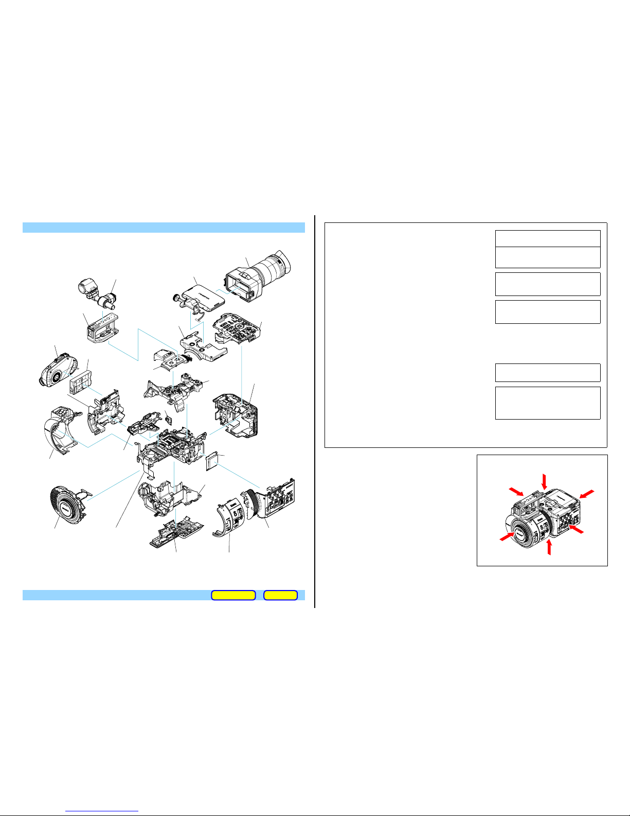
2. REPAIR PARTS LIST
Follow the disassembly in the numerical order given.
IDENTIFYING PARTS
Link
ACCESSORIES ASSEMBLY
View Position
Right View
Left View
Front View
Bottom View
Top View
Back View
・ Abbreviation
CH : Chinese model
CND : Canadian model
J : Japanese model
9 Cabinet (L (Front)) Section
2 Microphone Holder Section
5 Handle Block
1 VF Section
qd LCD Section
7 Cabi (Top (Rear)) Assy
8 Cabi (Top (Front)) Block
qf Control Panel Section
6 Bottom Cabinet Block
4 EXT Dummy
Cover (945)
w; MS-493 Board
wa US-020 Board
qg Cabinet (Top (Lower))
ql Main Frame (Lower)
qj BT Panel Section
ws Main Board Section
qh Cabinet (R (Rear) Section
qs Mount Block Section
qa Main Frame
(Front)
3 GRIP Section
• EF-001 Board
• IR-079 Board
• SS-190 Board
• HK-030 Board
• ML-028 Board
• FP-1579 Flexible Board
• XL-015 Board
qk Cabinet (L (Rear)) Section
• FP-1574 Flexible Board
• FB-226 Board
• LS-074 Board
0 Cabinet (R (Front)) Section
• ND-005 Board
• RK-003 Board
• TS-162 Board
• AU-263 Board
• HD-045 Board
• VC-650 Board
• FP-1406 Flexible Board
• FP-1569 Flexible Board
• FP-1570 Flexible Board
• FP-1571 Flexible Board
• FP-1572 Flexible Board
• FP-1573 Flexible Board
• JK-406 Board
• HP-161 Board
• XL-015 Board
• TK-073 Board
• PD-468 Board
• IS-102 Board
• MT-076 Board
• RF-056 Board
(ENGLISH)
NOTE:
• -XX, -X mean standardized parts, so they may have some differences from the
original one.
• Items marked “*” are not stocked since they are seldom required for routine service.
Some delay should be anticipated when ordering these items.
• The mechanical parts with no reference number in the exploded views are not
supplied.
• Due to standardization, replacements in the parts list may be different from the
parts specified in the diagrams or the components used on the set.
• CAPACITORS:
uF: μF
• COILS
uH: μH
• RESISTORS
All resistors are in ohms.
METAL: metal-film resistor
METAL OXIDE: Metal Oxide-film resistor
F: nonflammable
• SEMICONDUCTORS
In each case, u: μ, for example:
uA...: μA... , uPA... , μPA... ,
uPB... , μPB... , μPC... , μPC... ,
uPD..., μPD...
The components identified by mark 0 or dotted line with
mark 0 are critical for safety.
Replace only with part number specified.
Les composants identifiés par une marque 0 sont
critiques pour la sécurité.
Ne les remplacer que par une pièce portant le numéro
spécifié.
CAUTION
Danger of explosion if battery is incorrectly replaced.
Replace only with the same or equivalent type.
Dispose of used batteries according to the instructions.
注意
如果电池更换不当会有爆炸危险。
只能用同样类型或等效类型的电池来更换。
务必按照说明处置用完的电池。
• Color Indication of Appearance Parts
Example:
(SILVER) : Cabinet’s Color
(Silver) : Parts Color
(JAPANESE)
【使用上の注意】
• ここに記載されている部品は,補修用部品であるため,回路図及びセットに付い
ている部品と異なる場合があります。
• -XX,-Xは標準化部品のため,セットに付いている部品と異なる場合があります。
•*印の部品は常備在庫しておりません。
• コンデンサの単位でuFはμFを示します。
• 抵抗の単位Ωは省略してあります。
金 被:金属被膜抵抗。
サンキン:酸化金属被膜抵抗。
• インダクタの単位でuHはμHを示します。
• 半導体の名称でuA...,uPA...,uPB...,uPC...,uPD...等はそれぞれμA...,μPA..., μPB...,
μPC...,μPD...を示します。
0
印の部品,または0印付の点線で囲まれた部品は,
安全性を維持するために,重要な部品です。
従って交換時は,必ず指定の部品を使用してください。
注意
電池の交換は、正しく行わないと破裂する恐れがあり
ます。
電池を交換する場合には必ず同じ型名の電池又は同等
品と交換してください。
使用済み電池は、取扱指示に従って処分してください。
• 外装部品色表示
例:
(SILVER):セットの色を表す。
(Silver) :部品の色を表す。
2-2
NEX-FS700/FS700K/FS700C/FS700CK/FS700E/FS700EK/FS700J/FS700JK/FS700R/FS700RH/FS700U/FS700UK
– JAPANESE –
– ENGLISH –
作業時の注意
フレキシブル基板の導電面に汚れやごみなどがないことを確認してください。
フレキシブル基板の導電面を素手で触れないようにしてください。
フレキシブル基板は,コネクターの奥までまっすぐに差し込んでください。(図1,図2,図3参照)
OK
(奥までまっすぐに差し込んである)
NG
(斜めに差し込んである)
NG
(差し込み不十分)
コネクター コネクター
フレキシブル
基板
基準線
フレキシブル
基板
コネクター コネクター
基準線
フレキシブル
基板
フレキシブル
基板
コネクター コネクター
基準線
フレキシブル
基板
フレキシブル
基板
図1 図2 図3
コネクターの開閉部を開ける際,A方向に開け過ぎないようにし
てください。
コネクターの開閉部を閉じる際,フレキシブル基板を矢印B方向
に押しながら,開閉部を均一に押してください。
開閉部
コネクター
フレキシブル基板
A
A
開閉部
絶縁面
コネクター
フレキシブル基板
B
• フラットケーブルおよびフレキシブル基板の端子面に欠け,
折れ等がないことを確認してください。
• 金メッキされているフレキシブル基板には,強い負担をかけ
ないでください。
先端の剥がれたメッキ部はカットして
除去してください。
(メッキ破片がコネクター内に残って
いる場合もあるので注意してください)
• コネクターを取り外す際に,線材部(極細)を持って引っ張る
と断線する恐れがありますので,絶対に線材部(極細)を持っ
て引っ張らないでください。
• 線材部(極細)を押さえながらコネクターを差し込むと,線材
部(極細)が断線する恐れがありますので,絶対に線材部(極細)
には負担をかけないでください。
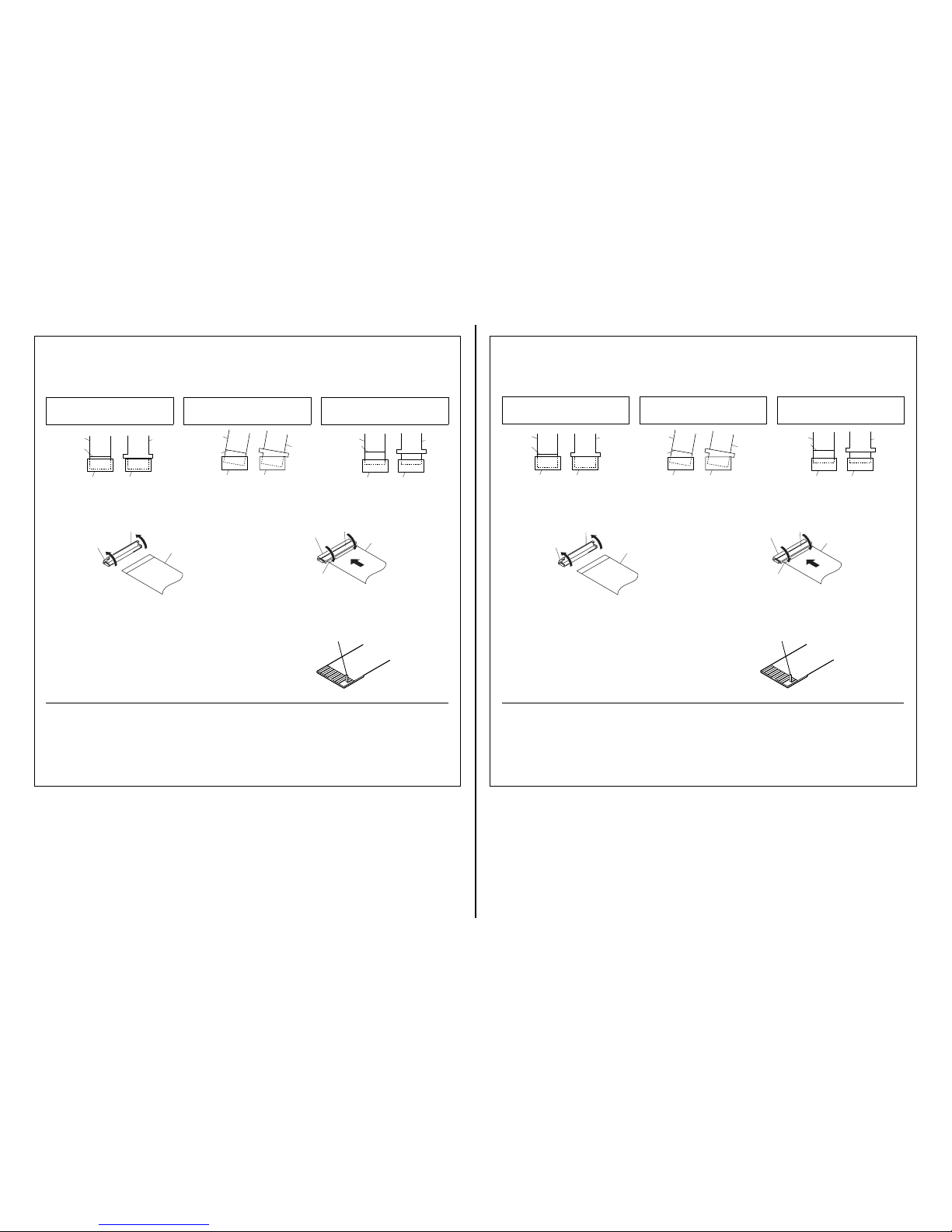
OPERATION NOTES
Make sure that the conductive side of a flexible board does not have any stain or foreign materials.
Do not touch the conductive side of flexible boards with bare hands.
Plug in a flexible board straight, fully into the connector until it reaches the end inside. (Fig. 1, Fig. 2, Fig. 3)
OK
(The flexible board was plugged in straight
and completely)
NG
(The flexible board was plugged in
crooked.)
NG
(The flexible board was not plugged in
completely.)
Flexible
Board
Flexible
Board
Connector Connector
Reference line
Flexible
Board
Connector Connector
Flexible
Board
Reference line
Connector Connector
Flexible
Board
Flexible
Board
Reference line
Fig. 1 Fig. 2 Fig. 3
When opening the connector's holder in direction A, do not open
it with excessive force.
When closing the connector's holder, press it evenly while pushing
a flexible board in direction B.
Holder
Connector
Flexible Board
A
A
Holder
Insulation side
Connector
Flexible Board
B
• Make sure that the flat cable and flexible board are not cracked
or bent at the contact end.
• Do not apply excessive force to the gilded flexible board.
Cut and remove the part of gilt
which comes off at the point.
(Be careful or some
pieces of gilt may be left inside)
• The proper way to disconnect a connector is to grab the connector instead of the wires. If you pull on the wires, they might
be broken.
• The proper way to connect a connector is to grab the connector
instead of the wires. If you push on the wires, they might be
broken.
2-3
NEX-FS700/FS700K/FS700C/FS700CK/FS700E/FS700EK/FS700J/FS700JK/FS700R/FS700RH/FS700U/FS700UK
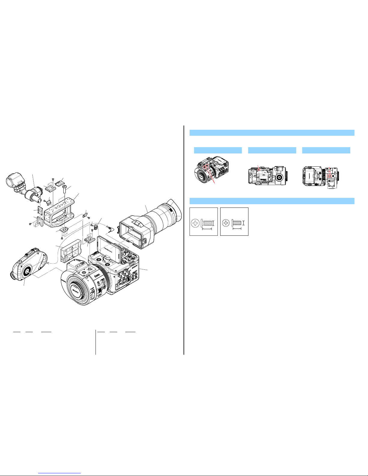
2-1. EXPLODED VIEWS
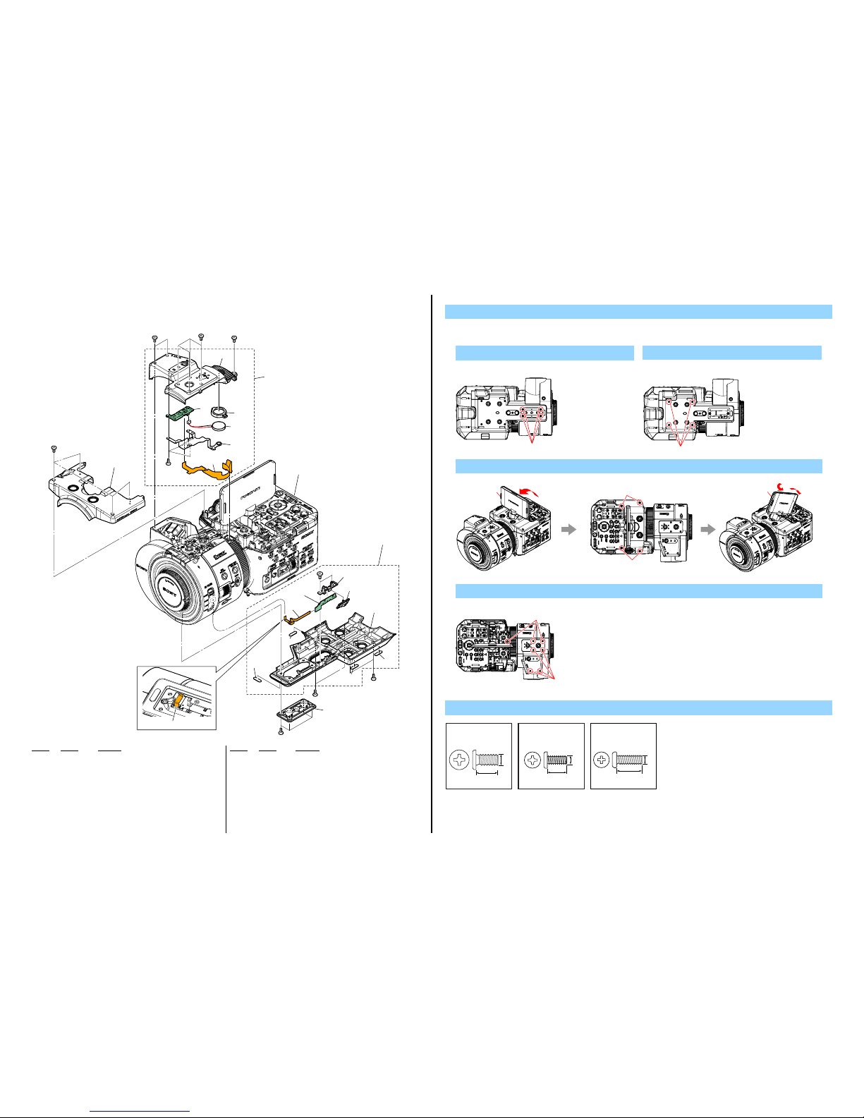
2-1-1. OVERALL SECTION-1
1. Remove in numerical order (1 to 7) in the left figure.
DISASSEMBLY
5 Ref. No. 9 X 2
Screw
Ref.No.9
#49:M2.0 X 4.0
(Black)
2-630-005-31
4.0
2.0
Ref. No. Part No. Description
Ref. No. Part No. Description
1 3-069-286-03 SHOE, ACCESSORY
2 3-288-615-02 SPRING, SHOE
3 4-425-263-01 HANDLE (960)
* 4 3-678-684-01 HOLDER, CABLE
5 4-284-205-01 SHEET METAL, HN SHOE
6 4-284-137-01 CLAMP, CABLE
7 3-069-286-31 SHOE, ACCESSORY
* 8 4-284-136-01 COVER (945), EXT DUMMY
9 4-425-264-01 KNOB, HANDLE FIXED
#49 2-630-005-31 SCREW (M2), NEW TRUSTER, P2
#233 2-342-356-11 SCREW (M2 (ECO, EG))
6 #49 X 1
Left View
#49
7 #233 X 4
Top View
#233
4
9
5
1
2
2
1
4
#233
#49
#49
#49
#49
#49
#49
3 Grip Section
(See page 2-17)
1 VF Section
(See page 2-18)
2 Microphone Holder Section
(See page 2-19)
3
5
6
6
7
7
Overall Section-2
(See page 2-4)
4 8
#233:
5.0
2.0
M2.0 X 5.0
(Black)
2-342-356-11
2-4
NEX-FS700/FS700K/FS700C/FS700CK/FS700E/FS700EK/FS700J/FS700JK/FS700R/FS700RH/FS700U/FS700UK
1. Remove in numerical order (1 to 4) in the left figure.
DISASSEMBLY
1 #272 X 4
Bottom View
#272
#53
ns
ns
SP901
#49
#49
#49
#49
60
(Note)
58
53
55
54
59
57
61
61
#272
Contact Side
#49
#49
ns
#53
61
61
4 52
2 56
3 51
1 62
Overall Section-3
(See page 2-5)
Ref. No. Part No. Description
Ref. No. Part No. Description
51 X-2584-333-1 CAB (TOP (REAR)) (960) ASSY
52 A-1885-369-A (TOP (FRONT)) BLOCK ASSY
53 2-178-550-01 HOLDER, SPEAKER
54 A-1885-288-A ML-028 BOARD, COMPLETE
55 1-885-673-11 FP-1579 FLEXIBLE BOARD
56 A-1885-368-A BOTTOM BLOCK ASSY, CABINET
57 4-425-295-01 BASE, HOLD SLIDE
58 A-1885-289-A HK-030 BOARD, COMPLETE
59 4-425-299-01 KNOB, HOLD
60 1-846-030-11 CABLE, FLEXIBLE FLAT (FFC-1023) (Note)
61 4-165-229-01 FOOT, RUBBER
62 3-288-392-11 WASHER (D), TRIPOD
SP901 1-858-706-11 LOUDSPEAKER (1.8CM)
#49 2-630-005-31 SCREW (M2), NEW TRUSTER, P2
#53 3-080-206-21 SCREW, TAPPING, P2
#272 7-627-556-78 SCREW, PRECISION +P 2.6X6 TYPE1
3 Open the LCD (3-1) → #49 X 4 → Rotate and Tilt LCD (3-2)
3-1
3-2
Top View
#49
#49
2-1-2. OVERALL SECTION-2
ns : not supplied
2 #49 X 4
Bottom View
#49
4 #49 X 7
Top View
#49
#49
Screw
#49:M2.0 X 4.0
(Black)
2-630-005-31
4.0
2.0
#53:M2.0 X 5.0 (Tapping)
(Black)
3-080-206-21
5.0
2.0
#272: M2.6 X 6.0
(Black)
7-627-556-78
6.0
2.6
2-5
NEX-FS700/FS700K/FS700C/FS700CK/FS700E/FS700EK/FS700J/FS700JK/FS700R/FS700RH/FS700U/FS700UK
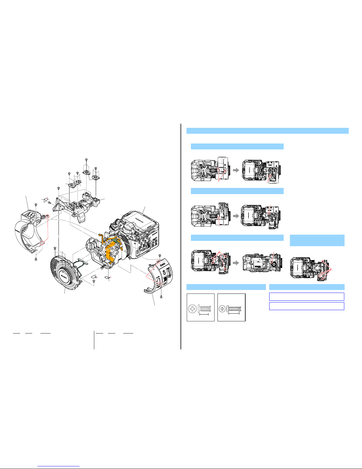
2-1-3. OVERALL SECTION-3
1. Remove in numerical order (1 to 4) in the left figure.
DISASSEMBLY
1 #49 X 3
Screw
Bottom View Top View
#49
#49
#49:M2.0 X 4.0
(Black)
2-630-005-31
4.0
2.0
#272: M2.6 X 6.0
(Black)
7-627-556-78
6.0
2.6
4-1
4-2
3
#49
103
3
#49
#49
#272
#272
#49
#272
#272
#272
#272
#272
#272
1
Cabinet (L (Front)) Section
(See page 2-10)
2
Cabinet (R (Front)) Section
(See page 2-10)
(Note)
Overall Section-4
(See page 2-6)
4
Mount Block Section
(See page 2-9)
2 (Claws)
1 (Claws)
101
102
101
104
104
105
2 #49 X 2
Bottom View Top View
#49
#49
Ref. No. Part No. Description
Ref. No. Part No. Description
101 4-269-036-01 PLATE, TRIPOD
102 4-269-035-01 PLATE, SHOE TRIPOD
103 4-425-253-01 FRAME (FRONT), MAIN
104 2-590-635-01 TAPE (AS 1/2)
105 4-428-226-01 SHEET, MT RADIATION
#49 2-630-005-31 SCREW (M2), NEW TRUSTER, P2
#272 7-627-556-78 SCREW, PRECISION +P 2.6X6 TYPE1
3 Remove Tape (AS 1/2) (3) → #272 X 5
Top View Left View
#272 #272
4 Remove Tape (AS 1/2) (4-
1) → Remove MT Radiation
Sheet (4-2) → #272 X 4
Top View
#272
Note
Note: Refer to “Assembly-1: Installation Cautions of the Cabinet
(R (Front)) Section.”.
Note:
“Assembly-1: Installation Cautions of the Cabinet (R
(Front)) Section.”を参照してください。
2-6
NEX-FS700/FS700K/FS700C/FS700CK/FS700E/FS700EK/FS700J/FS700JK/FS700R/FS700RH/FS700U/FS700UK
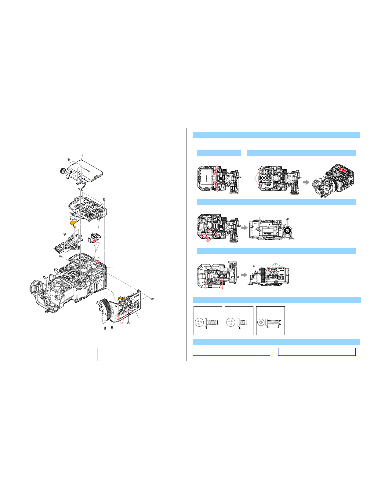
2-1-4. OVERALL SECTION-4
1. Remove in numerical order (1 to 5) in the left figure.
DISASSEMBLY
Ref. No. Part No. Description
Ref. No. Part No. Description
151 4-269-048-01 COVER, AU (Note)
152 4-269-049-01 CABINET (TOP (LOWER))
#49 2-630-005-31 SCREW (M2), NEW TRUSTER, P2
#269 2-655-582-01 SCREW 0+P2 M2 NEWTRU-STAR
#272 7-627-556-78 SCREW, PRECISION +P 2.6X6 TYPE1
#49
#269
#49
#49
#49
#49
#49
#272
151
(Note)
1
5 (Claws)
1 (Claw)
5
Cabinet (R) Section
(See page 2-13)
Overall Section-5
(See page 2-7)
2
LCD Section
(See page 2-11)
3
Control Panel Section
(See page 2-12)
152
4
3 (Claw)
2 #272 X 4
Top View
#272
#272
4 #49 X 5
Top View Left View
#49
#49
3 #49 X 2
Top View
#49
5 #269 X 1 → #49 X 5
Bottom View Right View
#49
#269
#49
Screw
#49:M2.0 X 4.0
(Black)
2-630-005-31
4.0
2.0
#269: M2.0 X 2.5
(Silver)
2-655-582-01
2.5
2.0
#272: M2.6 X 6.0
(Black)
7-627-556-78
6.0
2.6
Note
Note: Refer to “Assembly-2: Installation Cautions of the AU
Cover.”.
Note:
“Assembly-2: Installation Cautions of the AU Cover.”を参
照してください。
 Loading...