

Sony NEX-FS100CK, NEX-FS100JK, NEX-FS100EK, NEX-FS100J, NEX-FS100N Service Manual
...
SERVICE MANUAL
NEX-FS100C/FS100CK/FS100E/FS100EK/FS100J/FS100JK/FS100N/FS100NK/FS100P/FS100PK/FS100U/FS100UK
SERVICE NOTE (Check the following note before the service.)
Revision History
Published by Sony Techno Create Corporation
Sony Corporation
983458812.pdf
Ver. 1.1 2012.05
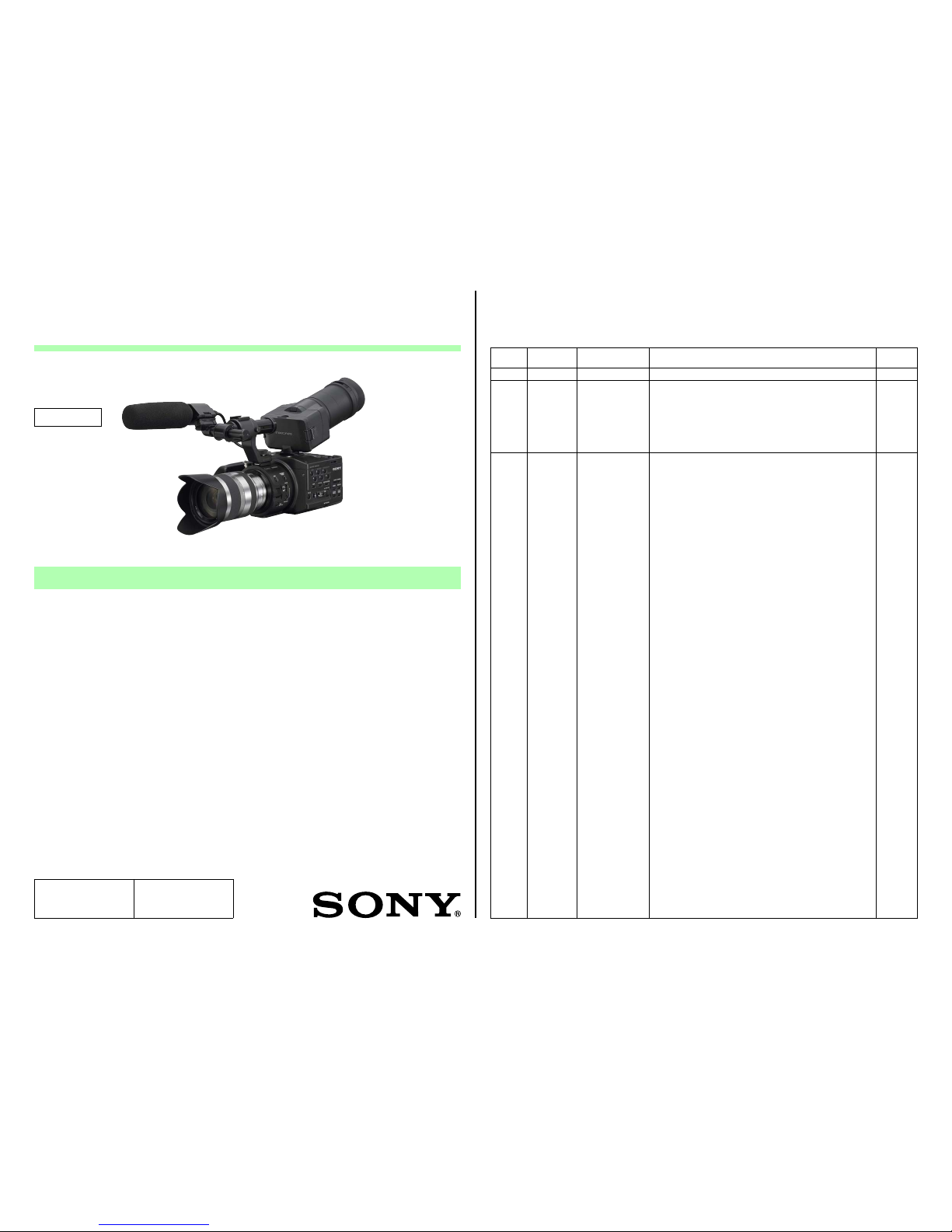
INTERCHANGEABLE LENS DIGITAL HD VIDEO CAMERA RECORDER
The components identified by mark
0 or dotted line with mark 0 are
critical for safety.
Replace only with part number
specified.
Les composants identifiés par une
marque 0 sont critiques pour la
sécurité.
Ne les remplacer que par une
pièce portant le numéro spécifié.
9-834-588-12
US Model
Canadian Model
AEP Model
E Model
Chinese Model
Japanese Model
Ver. Date History Contents
S.M. Rev.
issued
1.0 2011.05 Official Release — —
1.1 2012.05 Revised-1
(A1 12-050)
• Addition of SERVICE NOTE.
Page 1-1, 1-2, 1-3, 1-4
・
Correction of EXPLODED VIEWS.
Page 2-6, 2-8, 2-9, 2-11, 2-18, 2-19
・
Correction of ACCESSORIES.
Page 2-20
・
Correction of ELECTRICAL PARTS LIST.
Page 2-24
Yes
2012E08-1
© 2012.05
– ENGLISH –
1-1. POWER SUPPLY DURING REPAIRS
1-2. PRECAUTION ON REPLACING THE VC-618 BOARD
1-3. SELF-DIAGNOSIS FUNCTION
1-4. METHOD OF COPING WITH LENS ERROR
‒JAPANESE‒
1-1. 修理時の電源供給について
1-2. VC-618基板交換時の注意
1-3. 自己診断機能
1-4. レンズエラーの対処方法
[About the service of this model]
NEX-FS100CK/FS100EK/FS100JK/FS100NK/FS100PK/FS100UK is a commodity that packed the Interchangeable Lens
Digital HD Video Camera Recorder (NEX-FS100C/FS100E/FS100J/FS100N/FS100P/FS100U) and InterchangeableLens (E
18-200mm F3.5-6.3 OSS).
Refer to each following service manual of the Interchangeable Lens kit, when you repair.
・ Interchangeable Lens
SEL18200 (E 18-200mm F3.5-6.3 OSS) Service Manual (9-834-507-1[])
Photo: NEX-FS100UK
NEX-FS100C/FS100CK/FS100E/FS100EK/FS100J/FS100JK/
FS100N/FS100NK/FS100P/FS100PK/FS100U/FS100UK
Revised-1
Replace the previously issued
SERVICE MANUAL 9-834-588-11
with this Manual.
NEX-FS100C/FS100CK/FS100E/FS100EK/FS100J/FS100JK/FS100N/FS100NK/FS100P/FS100PK/FS100U/FS100UK
2-1
2. REPAIR PARTS LIST
Follow the disassembly in the numerical order given.
IDENTIFYING PARTS
Link
ACCESSORIES ASSEMBLY
(ENGLISH)
NOTE:
• -XX, -X mean standardized parts, so they may have some differences from the original
one.
• Items marked “*” are not stocked since they are seldom required for routine service.
Some delay should be anticipated when ordering these items.
• The mechanical parts with no reference number in the exploded views are not supplied.
• Due to standardization, replacements in the parts list may be different from the parts
specified in the diagrams or the components used on the set.
• CAPACITORS:
uF: μF
• COILS
uH: μH
• RESISTORS
All resistors are in ohms.
METAL: metal-film resistor
METAL OXIDE: Metal Oxide-film resistor
F: nonflammable
• SEMICONDUCTORS
In each case, u: μ, for example:
uA...: μA... , uPA... , μPA... ,
uPB... , μPB... , μPC... , μPC... ,
uPD..., μPD...
(JAPANESE)
【使用上の注意】
• ここに記載されている部品は,補修用部品であるため, 回路図及びセットに付いてい
る部品と異なる場合があります。
• -XX,-Xは標準化部品のため,セットに付いている部品と異なる場合があります。
•*印の部品は常備在庫しておりません。
• コンデンサの単位でuFはμFを示します。
• 抵抗の単位Ωは省略してあります。
金 被:金属被膜抵抗。
サンキン:酸化金属被膜抵抗。
• インダクタの単位でuHはμHを示します。
• 半導体の名称でuA...,uPA..., uPB...,uPC...,uPD...等はそれぞれμA.. .,μPA...,μPB...,
μPC...,μPD...を示します。
The components identified by mark 0
or dotted line with mark 0 are critical for
safety.
Replace only with part number specified.
Les composants identifiés par une marque
0 sont critiques pour la sécurité.
Ne les remplacer que par une pièce portant
le numéro spécifié.
• Color Indication of Appearance Parts
Example:
(SILVER) : Cabinet’s Color
(Silver) : Parts Color
View Position
Right View
Left View
Front View
Bottom View
Top Vi ew
Back View
・ Abbreviation
CH : Chinese model
CND : Canadian model
J : Japanese model
図面番号で部品を指定するときは基板名
又はブロックを併せて指定してください。
お願い
• 外装部品色表示
例:
(SILVER) :セットの色を表す。
(Silver) :部品の色を表す。
0
印の部品,または0印付の点線で囲ま
れた部品は,安全性を維持するために,
重要な部品です。
従って交換時は,必ず指定の部品を使用
してください。
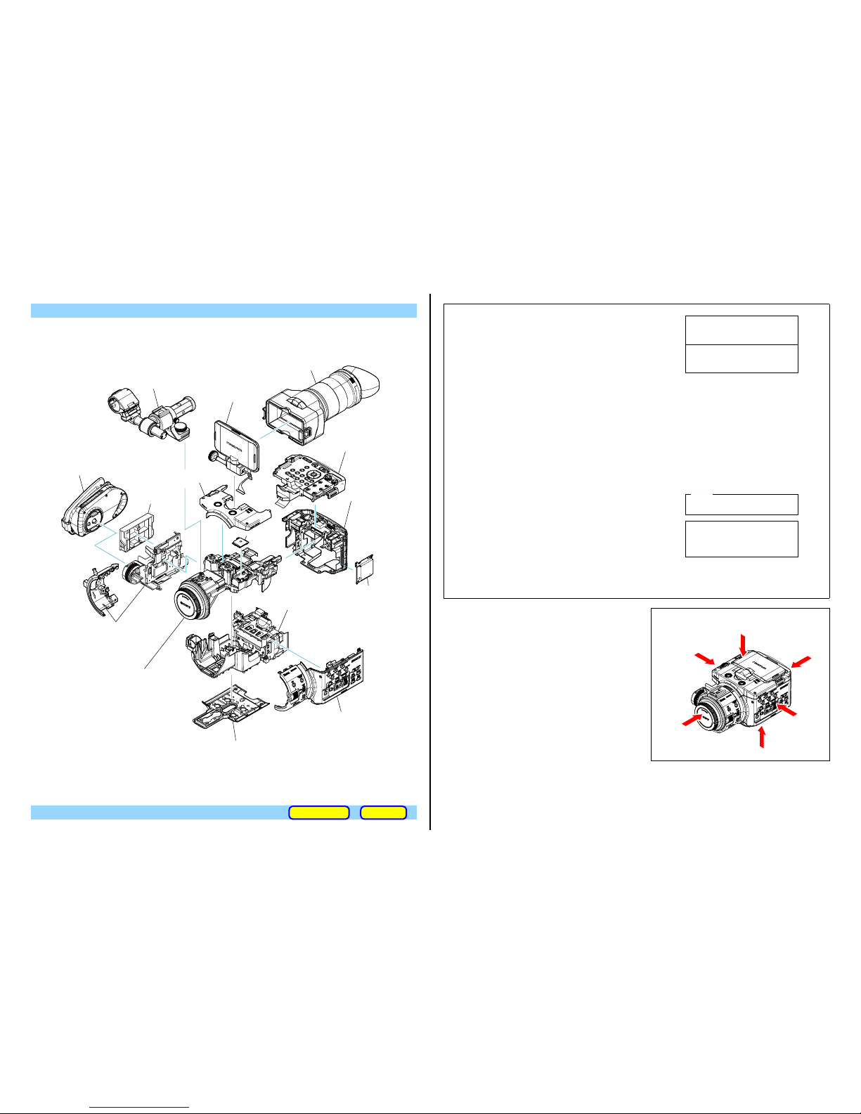
3 GRIP Section
• SS-186 Board
8 LCD Section
• PD-430 Board
qs Cabinet (L (Front))/
Cabinet (L (Rear) Section
• FB-225 Board
• LS-073 Board
qf Chassis (Upper) Section
• AU262 Board
• MT-072 Board
• VC-618 Board
• FP-1400 Flexible Board
• FP-1401 Flexible Board
• FP-1402 Flexible Board
• FP-1403 Flexible Board
• FP-1405 Flexible Board
• FP-1406 Flexible Board
• FP-1407 Flexible Board
• FP-1408 Flexible Board
1 VF Section
2 Handle Section
9 Control Panel Section
• TK-072 Board
qa BT Panel Section
• HP-159 Board
• JK-399 Board
• XL-014 Board
qg Chassis (Lower) Section
• HD-043 Board
• US-018 Board
• FP-1409 Flexible Board
• FP-1410 Flexible Board
q; Cabinet (R) Section
• RK-001 Board
• TS-159 Board
4 EXT Dummy
Cover (945)
7 GP945 Assy
5 Cabinet Bottom Assy
6 Cabinet (Top (Rear)) Assy
qd MS-460 Assy
NEX-FS100C/FS100CK/FS100E/FS100EK/FS100J/FS100JK/FS100N/FS100NK/FS100P/FS100PK/FS100U/FS100UK
2-2
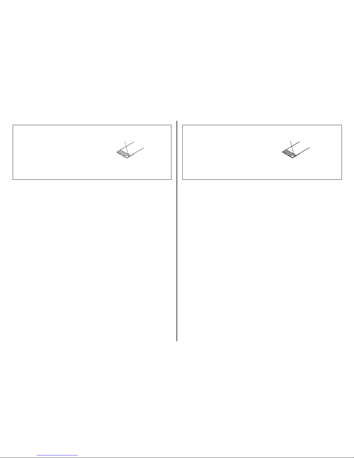
NOTE FOR REPAIR
• Make sure that the flat cable and flexible board are not cracked of
bent at the terminal.
Do not insert the cable insufficiently nor crookedly.
• When remove a connector, don’t pull at wire of connector. It is possible
that a wire is snapped.
• When installing a connector, don’t press down at wire of connector.
It is possible that a wire is snapped.
• Do not apply excessive load to the gilded flexible board.
Cut and remove the part of gilt
which comes off at the point.
(Be careful or some
pieces of gilt may be left inside)
– JAPANESE –
– ENGLISH –
修理時の注意
• フラットケーブルおよびフレキシブル基板の端子面に欠け,折れ等
がないことを確認する。
また,コネクタへの接続は,差し込み不足や斜め差しにならないよ
うに注意する。
• コネクタを取り外す時に,線材部(極細)を持って引っ張ると断線す
る恐れがありますので,絶対に線材部(極細)を持って引っ張らない
でください。
• 線材部(極細)を押さえながらコネクタを差し込むと,線材部(極細)
が断線する恐れがありますので,絶対に線材部(極細)には負担をか
けないでください。
• 金メッキされているフレキシブル基板には,強い負担をかけないで
ください。
వ┵ߩ߇ࠇߚࡔ࠶ࠠㇱߪࠞ࠶࠻ߒߡ
㒰ߒߡߊߛߐޕ
㧔ࡔ࠶ࠠ⎕ ߇ࠦࡀࠢ࠲ౝߦᱷߞߡࠆ
႐ว߽ࠆߩߢᵈᗧߒߡߊߛߐ㧕
వ┵ߩ߇ࠇߚࡔ࠶ࠠㇱߪࠞ࠶࠻ߒߡ
㒰ߒߡߊߛߐޕ
㧔ࡔ࠶ࠠ⎕ ߇ࠦࡀࠢ࠲ౝߦᱷߞߡࠆ
႐ว߽ࠆߩߢᵈᗧߒߡߊߛߐ㧕
NEX-FS100C/FS100CK/FS100E/FS100EK/FS100J/FS100JK/FS100N/FS100NK/FS100P/FS100PK/FS100U/FS100UK
2-3
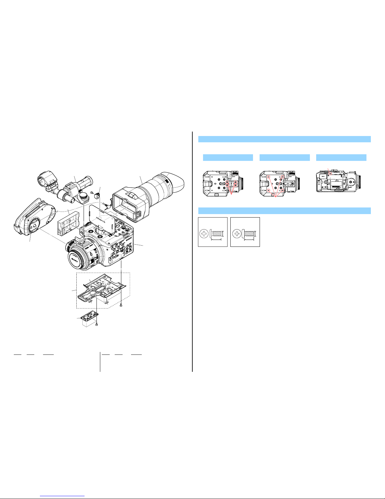
2-1. EXPLODED VIEWS
2-1-1. OVERALL SECTION-1
ns : not supplied
1. Remove to numerical order (
1 to 7) in the left figure.
DISASSEMBLY
5 #119 X 4
Screw
Bottom View
#119
#49:M2.0 X 4.0
(Black)
2-630-005-31
4.0
2.0
#119: M2.6 X 5.0
(Black)
7-627-556-58
5.0
2.6
ns
#49
#119
3 Grip Section
(See page 2-17)
7 1
6 3
5 5
4
4
2 Handle Section
(See page 2-19)
1 VF Section
(See page 2-18)
Overall Section-2
(See page 2-4)
#49
4 2
Ref. No. Part No. Description
Ref. No. Part No. Description
1 4-284-137-01 CLAMP, CABLE
* 2 4-284-136-01 COVER (945), EXT DUMMY
3 X-2581-568-1 BOTTOM ASSY, CABINET
4 4-165-229-01 FOOT, RUBBER
5 3-288-392-11 WASHER (D), TRIPOD
#49 2-630-005-31 SCREW (M2), NEW TRUSTER, P2
#119 7-627-556-58 SCREW +P 2.6X5
6 #49 X 4
Bottom View
#49
7 #49 X 1
Left View
#49
NEX-FS100C/FS100CK/FS100E/FS100EK/FS100J/FS100JK/FS100N/FS100NK/FS100P/FS100PK/FS100U/FS100UK
2-4
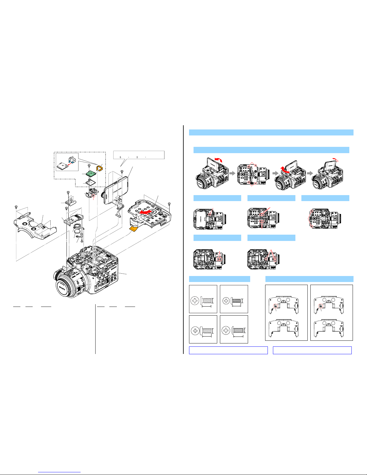
2-1-2. OVERALL SECTION-2
1. Remove to numerical order (1 to 7) in the left figure.
DISASSEMBLY
1
Stand up LCD → #49 X 4 → Rotate LCD → Tilt LCD
Screw
Top View
#49
#49
#49:M2.0 X 4.0
(Black)
2-630-005-31
4.0
2.0
#53:M2.0 X 5.0 (Tapping)
(Black)
3-080-206-21
5.0
2.0
Tighten these screws to the following torque.
#49
#49
#49
#191
Reinforcement side
60
#49
#53
SP901
56
58
(Claw)
5 Control Panel Section
(See page 2-12)
4 LCD Section
(See page 2-11)
1 51
(Note 1)
2 57
3 59
(Note 2)
6 52
7 53
54
55
(0.4 0.04N m (4.0 0.4kgf cm))
Overall Section-3
(See page 2-5)
Except FS100C/
FS100CK
Ref. No. Part No. Description
Ref. No. Part No. Description
51 X-2581-567-1 CABINET (TOP (REAR)) ASSY
(EXCEPT FS100C/FS100CK) (Note 1)
51 X-2581-569-1 CABINET (TOP (REAR)) CN ASSY
(FS100C/FS100CK) (Note 1)
52 3-069-286-31 SHOE, ACCESSORY
53 4-269-179-01 CABINET (TOP (FRONT))
54 2-178-550-01 HOLDER, SPEAKER
55 4-269-180-01 RETAINER, SP
56 1-839-082-11 CABLE, FLEXIBLE FLAT (FFC-246)
(EXCEPT FS100C/FS100CK)
57 A-1826-322-A GP945 ASSY (EXCEPT FS100C/FS100CK)
58 4-269-034-01 FRAME, GP (EXCEPT FS100C/FS100CK)
59 4-269-048-01 COVER, AU (Note 2)
60 3-637-901-02 SCREW M2.6X5
SP901 1-825-968-11 LOUDSPEAKER (1.8CM)
#49 2-630-005-31 SCREW (M2), NEW TRUSTER, P2
#53 3-080-206-21 SCREW, TAPPING, P2
#119 7-627-556-58 SCREW +P 2.6X5
#191 4-188-735-01 SCREW (M1.7)
2 #191 X 1
Top View
#191
4 Ref. No. 60 X 4
Top View
Ref. No. 60
Ref. No. 60
5 #49 X 2
Top Vi ew
#49
6 #49 X 4
Top View
#49
7 #49 X 3
Top View
#49
#119: M2.6 X 5.0
(Black)
7-627-556-58
5.0
2.6
#191: M1.7 X 3.5 (Tapping)
(Black)
4-188-735-01
3.5
1.7
Note
Note 1:
When replacing this part,
be careful whether a LOGO
is existed or not.
X-2581-567-1
GPS logo
X-2581-569-1
឵ᤨߦࡠࠧߩήߦᵈᗧ
ߒߡߊߛߐޕ
GPSߩࡠࠧ
Note 1:
X-2581-567-1
X-2581-569-1
Note 2: Refer to "Assembly-3: Installation Cautions of the AU
Cover.".
Note 2:
“Assembly-3: Installation Cautions of the AU Cover.” を参照
してください。
NEX-FS100C/FS100CK/FS100E/FS100EK/FS100J/FS100JK/FS100N/FS100NK/FS100P/FS100PK/FS100U/FS100UK
2-5
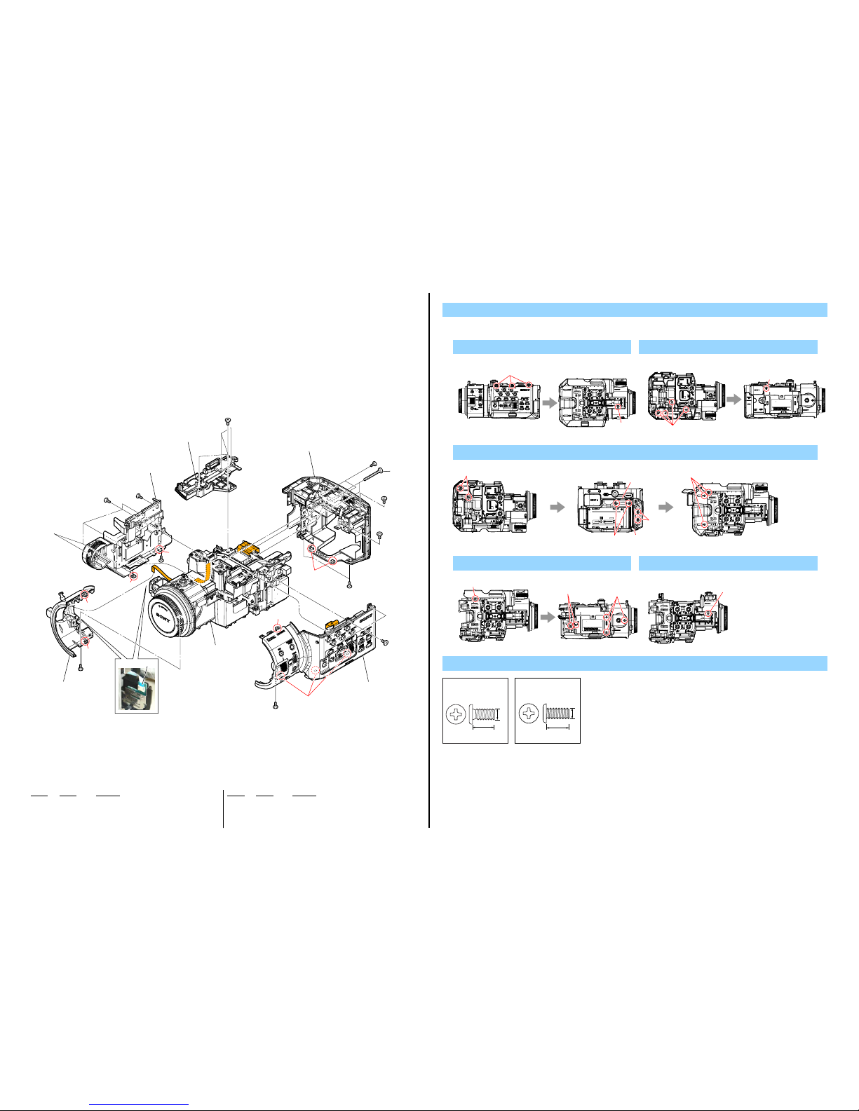
2-1-3. OVERALL SECTION-3
1. Remove to numerical order (1 to 5) in the left figure.
DISASSEMBLY
1 #49 X 4
Screw
Right View Bottom View
#49
#49
#49:M2.0 X 4.0
(Black)
2-630-005-31
4.0
2.0
#191: M1.7 X 3.5 (Tapping)
(Black)
4-188-735-01
3.5
1.7
#49
#49
#49
#49
#49
#49
#191
#49
#49
#49
#49
1 Cabinet (R) Section
(See page 2-13)
Chassis (Lower) Section
(See page 2-6)
3 BT Panel Section
(See page 2-14)
4 Cabinet (L (Front))/
Cabinet (L (Rear) Section
(See page 2-15)
5 Cabinet (L (Front))/
Cabinet (L (Rear) Section
(See page 2-15)
2 101
102
1(Claw)
4(Claw)
5(Claw)
4(Claw)
1(Claws)
3(Claws)
5(Claw)
Reinforcement side
2 #49 X 4 → #49 X 1
Top View Left View
#49
#49
3 #49 X 2 → Open HDMI Lid (3-1) → Ref.No.102 X 2 → Open HDMI Lid (3-2) → #191 X 2 → #49 X 3
Top View Bottom ViewBack View
#49
#191
#49
Ref.No.102
3-2
3-1
Ref. No. Part No. Description
Ref. No. Part No. Description
101 4-269-049-01 CABINET (TOP (LOWER))
102 7-621-775-80 SCREW +B 2.6X16
#49 2-630-005-31 SCREW (M2), NEW TRUSTER, P2
#191 4-188-735-01 SCREW (M1.7)
4 #49 X 6
Bottom View Left View
#49
#49
#49
5 #49 X 1
Bottom View
#49
NEX-FS100C/FS100CK/FS100E/FS100EK/FS100J/FS100JK/FS100N/FS100NK/FS100P/FS100PK/FS100U/FS100UK
2-6
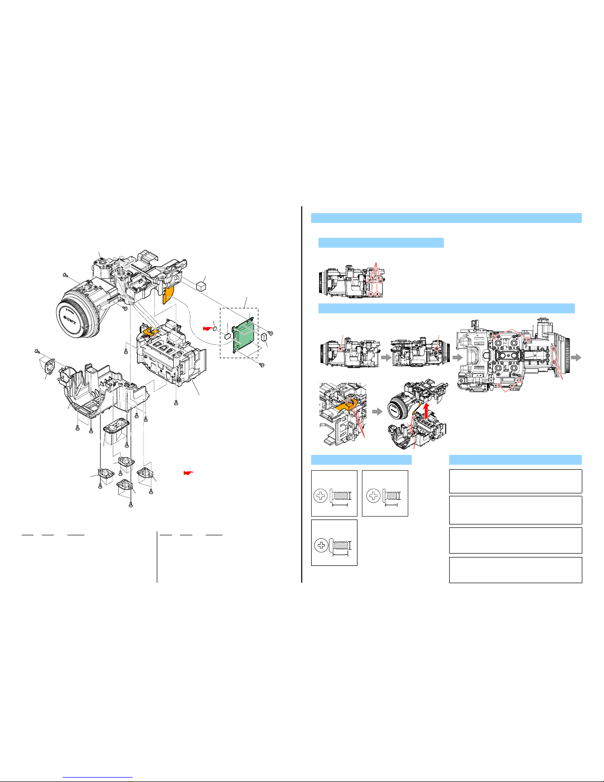
2-1-4. CHASSIS (LOWER) SECTION
ns : not supplied
#119
#119
#119
#119
#119
#49
#49
#49
#49
#50
157
#50
#49
157
157
#119
156
154
2 Chassis (Upper) Section
(See page 2-7)
BT Holder Section
(See page 2-16)
1 155
153
ns
BH2001
(Note)
BT2001
(Note)
151
151
151
152
151
151
: BT2001 (LITHIUM BATTERY SECONDARY)
Board on the mount position.
(See page 6-46)
1. Remove to numerical order (1 to 2) in the left figure.
DISASSEMBLY
1 #50 X 4
Right View
#50
Note
Note: Replace the battery holder (BH2001) together when replacing
the lithium storage battery (BT2001) on the MS-460 board. (The
battery holder removed once cannot be usedagain.)
When mounting these parts, mount new battery holder first and
attach new lithium storage battery next.
Note:
MS-460基板のリチウム蓄電池 ( BT2001) を交換する場合は
バッテリホルダ (BH2001) も同時に新品に交換してください。
(一度使用したバッテリホルダは再使用できません。)
部品取り付けの際は、先にバッテリホルダを取り付けてから
リチウム蓄電池を装着してください。
2 Ref. No. 157 X 4 → #49 X 4
Right View Left View Bottom View
Ref. No. 157
Hole
#49
#49
Disconnect
flexible boards,
harness
Ref. No. 157
Ref. No. 157
Ref. No. Part No. Description
Ref. No. Part No. Description
151 4-269-036-01 PLATE, TRIPOD
152 4-284-132-01 WASHER (D LARGE), TRIPOD
153 4-269-031-01 FRAME (LOWER), MAIN
154 4-284-134-01 GASKET (B)
155 A-1826-028-A MS-460 BOARD, COMPLETE
156 4-284-133-01 GASKET (A)
157 4-671-539-01 SCREW, M2 +P EG GRIP
BH2001 1-251-928-21 SOCKET, BATTERY (Note)
BT2001 1-756-135-31 BATTERY LITHIUM SECONDARY (Note)
#49 2-630-005-31 SCREW (M2), NEW TRUSTER, P2
#50 2-891-494-11 SCREW (M2), NEW TRUSTER, P2
#119 7-627-556-58 SCREW +P 2.6X5
Caution :
Danger of explosion if battery is incorrectly replaced.
Replace only with the same or equivalent type.
Dispose of used batteries according to the instructions.
注意
電池の交換は、正しく行わないと破裂する恐れがあります。
電池を交換する場合には必ず同じ型名の電池又は同等品と交換してく
ださい。
使用済み電池は、取扱指示に従って処分してください。
Screw
#49:M2.0 X 4.0
(Black)
2-630-005-31
4.0
2.0
#50:M2.0 X 3.0
(Red)
2-891-494-11
3.0
2.0
#119: M2.6 X 5.0
(Black)
7-627-556-58
5.0
2.6
The changed portions from
Ver. 1.0 are shown in blue.
Ver. 1.1 2012.05
 Loading...