

Sony MZ-NF810CK,MZ-NF810 Service Manual
SERVICE MANUAL
PORTABLE MINIDISC RECORDER
US Model
Canadian Model
MZ-NF810CK
AEP Model
UK Model
E Model
Austr alian Model
Chinese Model
Tourist Model
MZ-NF810
SPECIFICATIONS
MZ-NF810/NF810CK
US and foreign patents licensed from Dolby
Laboratories.
– Continued on next page –
Model Name Using Similar Mechanism MZ-R410
Mechanism Type MT-MZN710-177
Optical Pick-up Name LCX-5R
Ver 1.0 2003. 03
9-877-145-01 Sony Corporation
2003C167800-1 Personal Audio Company
C 2003.03 Published by Sony Engineering Corporation
• SonicStage, OpenMG and the OpenMG
logo, MagicGate, Memory Stick and the
MagicGate Memory Stick logo,
Memory Stick and the Memory Stick
logo, Net MD and the Net MD logo are
trademarks of Sony Corporation.
• Microsoft, Windows, Windows NT and
Windows Media are trademarks or
registered trademarks of Microsoft
Corporation in the United States and /or
other countries.
• IBM and PC/AT are registered
trademarks of International Business
Machines Corporation.
• Macintosh is a trademark of Apple
Computer, Inc. in the United States and/
or other countries.
• MMX and Pentium are trademarks or
registered trademarks of Intel
Corporation.
Photo : MZ-NF810
MD recorder
Audio playing system
MiniDisc digital audio system
Laser diode properties
Material: GaAlAs
Wav el ength: λ = 790 nm
Emission duration: continuous
Laser output: less than 44.6 µW
(This output is the value measured at a distance
of 200 mm from the lens surface on the optical
pick-up block with 7 mm aperture.)
Recording and playback time (when
using MDW-80)
Maximum 160 min. in monaural
Maximum 320 min. in LP4 stereo
Revolutions
380 rpm to 2,700 rpm (CLV)
Error correction
ACIRC (Advanced Cross Interleave Reed
Solomon Code)
Sampling frequency
44.1 kHz
Sampling rate converter
Input: 32 kHz/44.1 kHz/48 kHz
Coding
AT RAC (Adaptive TRansform Acoustic
Coding)
AT RA C 3 — LP2/LP4

2
MZ-NF810/NF810CK
Radio
Frequency range
USA model:
FM: 87.5 - 108.0 MHz
AM: 530 - 1,710 kHz (10 kHz step)
531 - 1,710 kHz (9 kHz step)
TV: 2 - 13 CH
WEATHER: 1 - 7 CH
Canadian model:
FM: 87.5 - 108.0 MHz
AM: 530 - 1,710 kHz (10 kHz step)
531 - 1,710 kHz (9 kHz step)
Antenna
FM/TV/WEATHER:
Headphones/earphones cord antenna
AM:
Built-in ferrite bar antenna
General
Power requirements
Sony AC Power Adaptor connected at the DC
IN 3V jack:
120 V AC, 60 Hz (Models for USA, Canada,
Mexico, and Taiwan)
230 V AC, 50/60 Hz (Models for continental
Europe and Chili)
240 V AC, 50 Hz (Model for Australia)
220 V AC, 50 Hz (Model for China)
230 V AC, 50 Hz (Models for U.K. and
Hong Kong)
220 V AC, 60 Hz (Model for Korea)
100 - 120 V/220 - 240 V AC, 50/60 Hz
(Other models)
The recorder:
Nickel metal hydride rechargeable battery
NH-10WM 1.2V 900 mAh (MIN) Ni-MH
LR6 (size AA) alkaline battery
Battery charging stand:
AC power adaptor DC 3V
Dimensions
Approx. 81.0 × 74.4 × 20.0 mm (w/h/d)
(3
1
/4 × 3 × 13/16 in.)
Mass
Approx. 108 g (3.8 oz) the recorder only
1)
The LINE IN (OPTICAL) jack is used to
connect either a digital (optical) cable or a line
(analog) cable.
2)
The i jack connects either headphones/
earphones or a line cable.
3)
Measured in accordance with JEITA.
Car kit
Car connecting pack
Frequency response: 50 to 20,000Hz (Differs
depending on your car cassette deck)
Dimensions: Approx. 102.4 × 12.1 × 63.8 mm
(w/h/d) (4
1
/8 × 1/2 × 25/8 in.)
Mass: Approx. 42 g (1.5 oz)
Cord length: Approx. 1.5 m
Car battery cord
Input voltage: DC 12 V/24 V (only for negative
# ground cars)
Rated output voltage: DC 3.0 V
Rated output current: 1,000 mA
Dimensions: Approx. 36.0 × 26.2 × 101.1 mm
(w/h/d) (1
7
/16 × 11/16 × 4 in.) including
projecting parts
Mass: Approx. 60 g (2.2 oz)
Cord length: Approx. 1.5 m
US and foreign patents licensed from Dolby
Laboratories.
Design and specifications are subject to change
without notice.
When playing
(Unit: approx.hours)(JEITA)
When using the radio
(Unit: approx.hours)(JEITA)
Note
When you use the radio, it is recommended that
you use a fully charged rechargeable battery or
a new dry battery since more power is
consumed by the radio than by MD playback.
When to replace the batteries
When the dry battery or rechargeable
battery is weak, flashing r or “LOW
BATT” appears in the display. Replace the
dry battery or charge the rechargeable
battery.
The battery level indicator is approximate.
It may be more or less than the indication
depending on the operating condition.
Note
Stop the recorder before replacing battery.
Ba
Supplied accessories
ttery life
The battery life may be shorter due to
operating conditions, the temperature of
the location, or alkaline dry battery you
use.
When recording
(Unit: approx.hours)(JEITA1))
1)
Measured in accordance with the JEITA
(Japan Electronics and Information
Technology Industries Association) standard.
Batteries SP
Stereo
LP2
Stereo
LP4
Stereo
Nickel metal
hydride
rechargeable
battery
2)
2)
When using a 100% fully charged nickel metal
hydride rechargeable battery (NH-10WM).
7912
LR6 Sony
alkaline dry
battery
3)
3)
When using a Sony LR6 (SG) “STAMINA”
alkaline dry battery (produced in Japan).
12 15 18.5
Nickel metal
hydride
rechargeable
battery + One
LR6
22 30 35
Batteries SP
Stereo
LP2
Stereo
LP4
Stereo
Nickel metal
hydride
rechargeable
battery
17 21 23.5
LR6 Sony
alkaline dry
battery
38 44 50.5
Nickel metal
hydride
rechargeable
battery + One
LR6
57 66.5 73.5
Batteries FM/AMTV/Wb
(weather)
(USA
model only)
Nickel metal hydride
rechargeable battery
99
LR6 (SG) Sony
alkaline dry battery
18.5 17
Nickel metal
hydride
rechargeable battery
+ One LR6 (SG)
29 23
Modulation system
EFM (Eight to Fourteen Modulation)
Frequency response
20 to 20,000 Hz ± 3 dB
Inputs
1)
MIC: stereo mini-jack
(minimum input level 0.12 mV)
Line in:
stereo mini-jack for analog input
(minimum input level 49 mV)
optical (digital) mini-jack for optical
(digital) input
Outputs
i: stereo mini-jack
Maximum output level
5 mW + 5 mW; load impedance 16Ω
Optical cable (1)
CD-ROM (SonicStage Ver. 1.5) (1)
∗
Car battery cord (1)
Car connecting pack (1)
Carrying case with Velcro strips (1)
Carrying case with a belt clip (1)
(Canadian model only)
∗Do not play a CD-ROM on an audio CD player.
AC power adaptor (1)
Battery charging stand (1)
Headphones with a remote control (1)
(for USA model)
NH-10WM Nickel metal hydride
rechargeable battery (1)
Dedicated USB cable (1)
Battery carrying case (1)
Dry battery case (1)
Rotary commander (1)
Earphones with a remote control (1)
(for Canadian model)
3
MZ-NF810/NF810CK
TABLE OF CONTENTS
1. SERVICING NOTES ................................................ 4
2. GENERAL ................................................................... 5
3. DISASSEMBLY
3-1. Disassembly Flow ........................................................... 6
3-2. Case (Lower)................................................................... 7
3-3. MAIN Board, Battery Case ............................................ 7
3-4. Panel (Upper) Section..................................................... 8
3-5. LCD Module, Panel Upper Block .................................. 8
3-6. Mechanism Deck (MT-MZN710-177) ........................... 9
3-7. OP Service Assy (LCX-5R) ............................................ 10
3-8. Holder Assy..................................................................... 11
3-9. DC Motor (Sled) (M602)................................................ 11
3-10. DC Motor (Over Write Head Up/Down) (M603),
DC SSM18B Motor (Spindle) (M601)........................... 12
4. TEST MODE ............................................................... 13
5. ELECTRICAL ADJUSTMENTS.......................... 18
6. DIAGRAMS
6-1. Block Diagram ................................................................ 37
6-2. Note for Printed Wiring Board and
Schematic Diagrams ....................................................... 38
6-3. Printed Wiring Board
– MAIN Board (Side A) – ............................................. 39
6-4. Printed Wiring Board
– MAIN Board (Side B) – ............................................. 40
6-5. Schematic Diagram – MAIN Board (1/4) – .................. 41
6-6. Schematic Diagram – MAIN Board (2/4) – .................. 42
6-7. Schematic Diagram – MAIN Board (3/4) – .................. 43
6-8. Schematic Diagram – MAIN Board (4/4) – .................. 44
6-9. IC Pin Function Description ........................................... 50
7. EXPLODED VIEWS
7-1. Case Section.................................................................... 56
7-2. Chassis Section ............................................................... 57
7-3. MAIN Board Section ...................................................... 58
7-4. Mechanism Deck Section-1 (MT-MZN710-177) ........... 59
7-5. Mechanism Deck Section-2 (MT-MZN710-177) ........... 60
8. ELECTRICAL PARTS LIST.................................. 61
CAUTION
Use of controls or adjustments or performance of procedures
other than those specified herein may result in hazardous radiation exposure.
Notes on chip component replacement
•Never reuse a disconnected chip component.
• Notice that the minus side of a tantalum capacitor may be damaged by heat.
Flexible Circuit Board Repairing
•Keep the temperature of the soldering iron around 270 ˚C during repairing.
• Do not touch the soldering iron on the same conductor of the
circuit board (within 3 times).
• Be careful not to apply force on the conductor when soldering
or unsoldering.
UNLEADED SOLDER
Boards requiring use of unleaded solder are printed with the leadfree mark (LF) indicating the solder contains no lead.
(Caution: Some printed circuit boards may not come printed with
the lead free mark due to their particular size)
: LEAD FREE MARK
Unleaded solder has the following characteristics.
• Unleaded solder melts at a temperature about 40 ˚C higher than
ordinary solder.
Ordinary soldering irons can be used but the iron tip has to be
applied to the solder joint for a slightly longer time.
Soldering irons using a temperature regulator should be set to
about 350 ˚C .
Caution: The printed pattern (copper foil) may peel away if the
heated tip is applied for too long, so be careful!
• Strong viscosity
Unleaded solder is more viscous (sticky , less prone to flow) than
ordinary solder so use caution not to let solder bridges occur
such as on IC pins, etc.
• Usable with ordinary solder
It is best to use only unleaded solder but unleaded solder may
also be added to ordinary solder.
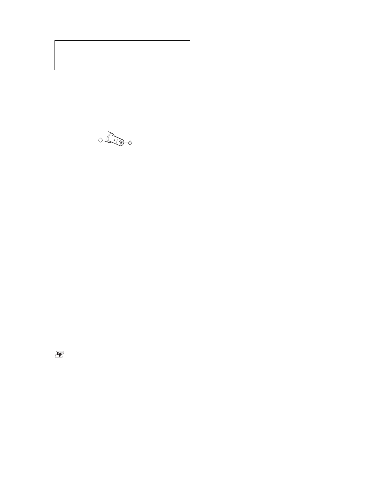
On power sources
• Use house current, nickel metal hydride
rechargeable battery, LR6 (size AA) battery,
or car battery.
•
For use in your house: For the supplied battery
charging stand, use the AC power adaptor
supplied with this recorder. Do not use any other
AC power adaptor since it may cause the recorder
to malfunction.
• Connect the AC power adaptor to an easi ly
accessible AC outlet. Should you notice an
abnormality in the AC power adaptor,
disconnect it from the AC outlet immediately.
• The recorder is not disconnected from the AC
power source (mains) as long as it is
connected to the wa ll ou tl et, even if the
recorder itself has been turned off.
• If you are not going to use this recorder for a
long time, be sure to disconnect the power
supply (AC power adaptor, dry battery,
rechargeable battery, or car battery cord). To
remove the AC power adaptor from the wall
outlet, grasp the adaptor plug itself; never pull
the cord.
Polarity of the
plug
SAFETY-RELATED COMPONENT WARNING!!
COMPONENTS IDENTIFIED BY MARK 0 OR DOTTED LINE
WITH MARK 0 ON THE SCHEMATIC DIAGRAMS AND IN THE
PARTS LIST ARE CRITICAL TO SAFE OPERATION. REPLACE
THESE COMPONENTS WITH SONY PARTS WHOSE P ART NUMBERS APPEAR AS SHOWN IN THIS MANUAL OR IN SUPPLEMENTS PUBLISHED BY SONY.
ATTENTION AU COMPOSANT AYANT RAPPORT
À LA SÉCURITÉ!
LES COMPOSANTS IDENTIFÉS P AR UNE MARQUE 0 SUR LES
DIAGRAMMES SCHÉMATIQUES ET LA LISTE DES PIÈCES
SONT CRITIQUES POUR LA SÉCURITÉ DE FONCTIONNEMENT .
NE REMPLACER CES COMPOSANTS QUE PAR DES PIÈSES
SONY DONT LES NUMÉROS SONT DONNÉS DANS CE MANUEL
OU DANS LES SUPPÉMENTS PUBLIÉS PAR SONY.
4
MZ-NF810/NF810CK
NOTES ON HANDLING THE OPTICAL PICK-UP
BLOCK OR BASE UNIT
The laser diode in the optical pick-up block may suffer electrostatic break-down because of the potential difference generated
by the charged electrostatic load, etc. on clothing and the human
body.
During repair, pay attention to electrostatic break-down and also
use the procedure in the printed matter which is included in the
repair parts.
The flexible board is easily damaged and should be handled with
care.
NOTES ON LASER DIODE EMISSION CHECK
Never look into the laser diode emission from right above when
checking it for adjustment. It is feared that you will lose your sight.
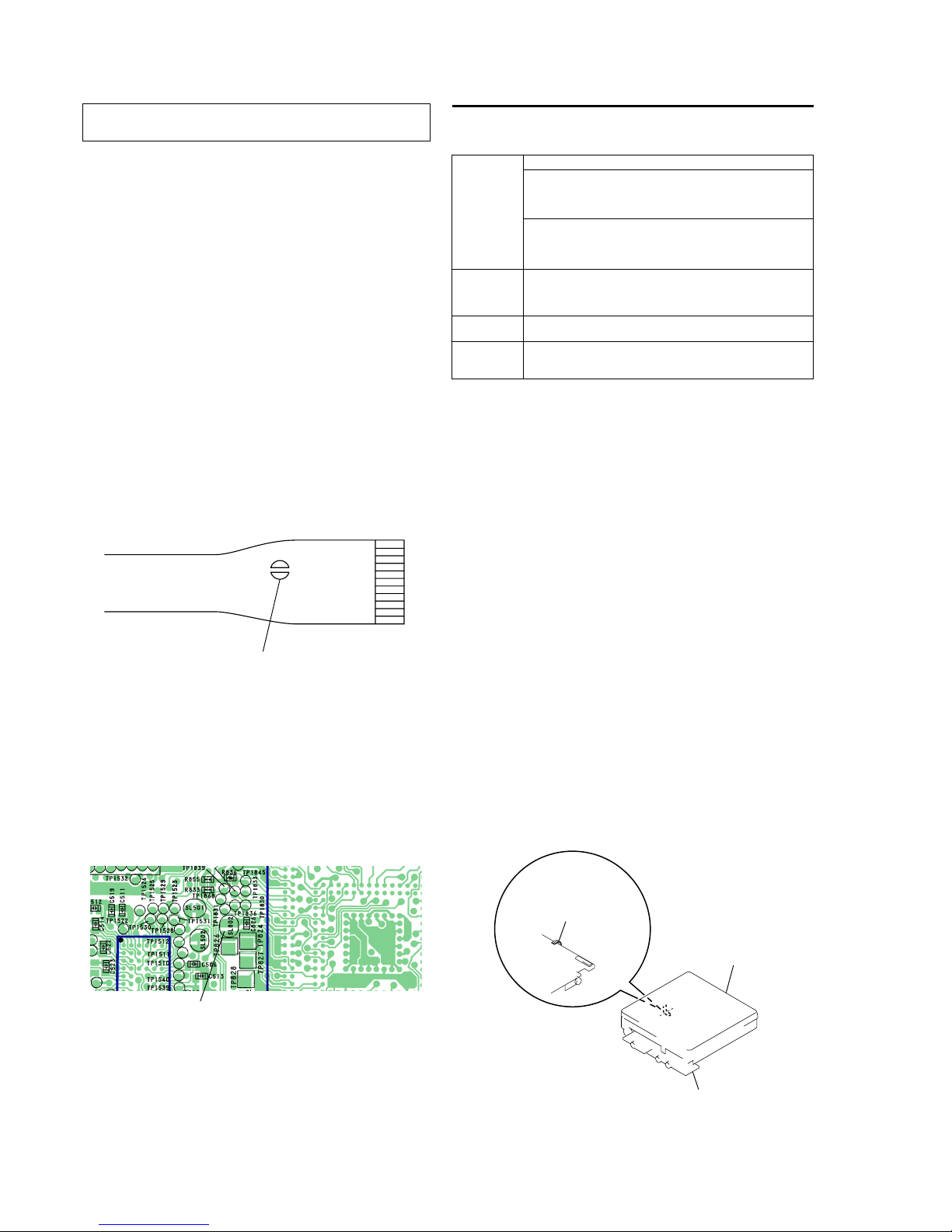
NOTES ON HANDLING THE OPTICAL PICK-UP BLOCK
(LCX-5R)
The laser diode in the optical pick-up block may suffer electrostatic break-down easily. When handling it, perform soldering
bridge to the laser-tap on the flexible board. Also perform measures against electrostatic break-down sufficiently before the operation. The flexible board is easily damaged and should be handled
with care.
OPTICAL PICK-UP FLEXIBLE BOARD
SECTION 1
SERVICING NOTES
laser-tap
• In performing the repair with the power supplied to the set, removing the MAIN board causes the set to be disabled.
In such a case, make a solder bridge to short SL802 (OPEN/
CLOSE) on the MAIN board.
• Handle the FLEXIBLE board (over write head) with care, as it
has been soldered directly to the MAIN board.
In repairing the component side of MAIN board, connect the
FLEXIBLE board (over write head) and the MAIN board with
the lead wires in advance.
System requirements
The following hardware and software are required in order to use the SonicStage software
for the Net MD.
This software is not supported by the following environments:
• Macintosh
• Windows XP versions other than Home Edition or Professional
• Windows 2000 versions other than Professional
• Windows 98 versions other than Second Edition
• Windows NT
• Windows 95
• Personally constructed PCs or operating systems
• An environment that is an upgrade of the original manufacturer-installed operating system
• Multi-boot environment
• Multi-monitor environment
Notes
• We do not ensure trouble-free operation on all computers that satisfy the system requirements.
• We do not ensure trouble-free operation of the system suspend, sleep, or hibernation function on all
computers.
Computer IBM PC/AT or Compatible
CPU: Pentium II 400 MHz or higher (Pentium III 450 MHz or higher
is recommended.)
Hard disk drive space
1)
: 120 MB or more
RAM: 64 MB or higher (128 MB or higher is recommended)
1)
Others
CD-ROM drive (capable of digital playback by WDM)
Sound Board
USB port (supports USB 2.0 Full Speed (previously USB 1.1))
Operating
System
Factory installed:
Windows XP Home Edition/Windows XP Professional/Windows
Millennium Edition/Windows 2000 Professional/Windows 98 Second
Edition
Display High Color (16bit) or greater, 800 ⋅ 480 dots or more (800 ⋅ 600 dots
or more is recommended)
Others Internet access: for Web registration and EMD services
Windows Media Player (version 7.0 or higher) installed for playing
WMA files
Note on hard disk drive space
120 MB or more free space on the hard disk drive is required. If your computer does not
have enough space, the software will not be properly installed. The required free space
differs according to the version of your Windows OS, or the amount of audio files that you
handle.
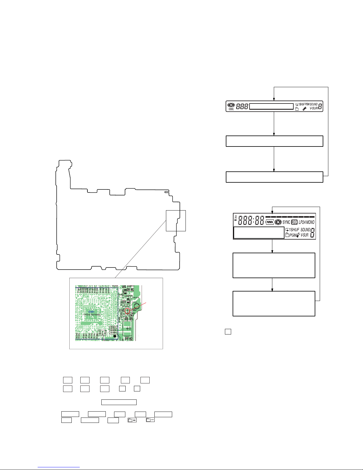
•This set requires the patch data in the nonvolatile memory
(IC851) to be rewritten using the application, when the MAIN
board was replaced. (See page 28)
upper panel ass
y
MAIN board
FLEXIBLE board
(over write head)
IC801
IC501
TP1524
TP1519
*
CSP(Chip Size Package)
*
CSP
(Chip
Size
Packa
ge)
SL802
(OPEN/CLOSE)
– MAIN Board (Side B) –
5
MZ-NF810/NF810CK
SECTION 2
GENERAL
This section is extracted from
instruction manual.
14
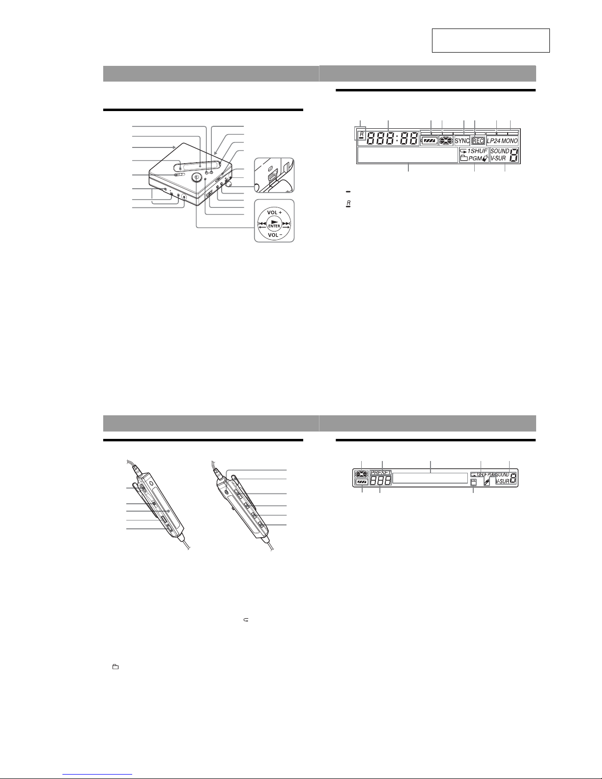
Looking at controls
The recorder
A x • CANCEL/CHG button
B Display window
C Battery compartment
D GROUP button
E REC (record) switch
F Ter min als for attaching dry battery
case
G Ter min als for attaching the battery
charging stand
H DC IN 3V jack
I X button
J OPEN switch
K END SEARCH button
L T MARK button
M HOLD switch
To prev ent the buttons from being
accidentally operated when you carry
the recorder, use this function.
N Handstrap hole
Use the hole to attach your own strap.
O USB cable connecting jack
P LINE IN (OPTICAL) jack
Q MIC (PLUG IN POWER) jack
There is a tactile dot beside the MIC
(PLUG IN POWER) jack.
R i (headphones/earphones)
S MENU button
T 5-way control key
N* • ENTER
. • T
> • t
VOL +
*
, –
* N and VOL + have a tactile dot.
2
1
4
w;
qg
3
5
6
7
9
qa
qs
qd
qh
qj
qk
ql
qf
q;
8
15
The display window of the recorder
A : Indication for remaining playing
time of the current track or of the disc
: Indication for remaining
recordable time of the disc
B Time display
C Battery indication
Shows approximate battery condition.
D Disc indication
Shows that the disc is rotating for
recording, playing or editing an MD.
E SYNC (synchro-recording) indication
F REC indication
Lights up while recording. When
flashing, the recorder is in record
standby mode.
G LP2 (LP2 stereo), LP4 (LP4 stereo),
MONO (monaural) indication
H Level meter
I Character information display
Displays the disc and track names,
date, error messages , track numbers,
etc.
J Play mode indications
Shows the play mode (shuffle play,
program play, repeat play, etc.) of the
MD.
K Sound indications
21345678
9q;qa
16
The headphones/earphones with a remote control
A VOL+, – buttons
Press to adjust the volume.
B Jog lever (. • NX/ENT • >,
TUNE – • BAND • TUNE +)
NX/ENT (to press): play, pause,
enter
.(to slide towards): REW
> (to slide towards): FF
BAND (to press): select a band
TUNE – (to slide towards): tune
backwards
TUNE + (to slide towards): tune
forward
C Display window
D x (stop) button
E (group) +, – buttons
F RADIO ON/OFF button
Press to turn on or off the radio.
G Clip
H HOLD switch
To prev ent the buttons from being
accidentally operated when you carry
the recorder, use this function.
I DISPLAY button
J P-MODE/ button
K SOUND button
F
G
H
I
J
K
B
C
D
E
A
17
The display window of the remote control
A Disc indication
B PRESET indication
C Character information display
D Play mode indication
E SOUND indication
F Battery level indication
G Trac k number/Band/Preset number
display
H Group indication
F
HG
BACDE
6
MZ-NF810/NF810CK
SECTION 3
DISASSEMBLY
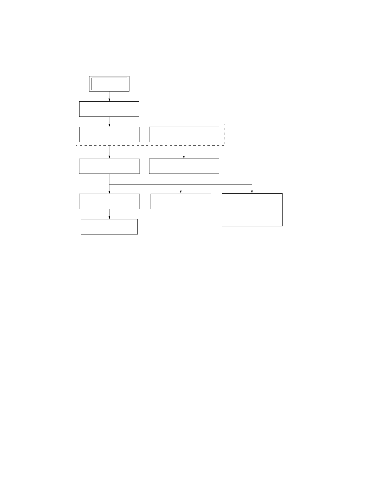
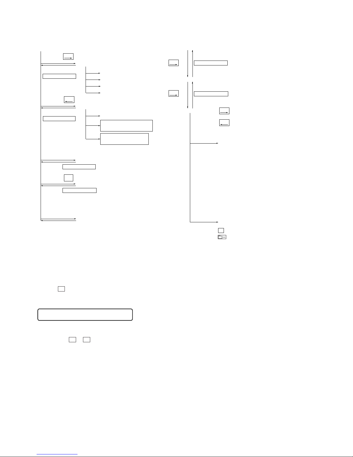
• This set can be disassembled in the order shown below.
3-1. Disassembly Flow
CASE (LOWER)
PANEL (UPPER) SECTION
In order to remove mechanism deck (MT-MZN710-177) ,
please remove MAIN board and upper panel section.
LCD MODULE,
PANEL UPPER BLOCK
MAIN BOARD,
BATTERY CASE
MECHANISM DECK
(MT-MZN710-177)
OP SERVICE ASSY
(LCX-5R)
HOLDER ASSY
DC MOTOR
(SLED) (M602)
DC MOTOR (OVER
WRITE HEAD UP/DOWN)
(M603),
DC SSM18B MOTOR
(SPINDLE) (M601)
SET
7
MZ-NF810/NF810CK
Note: Follow the disassembly procedure in the numerical order given.
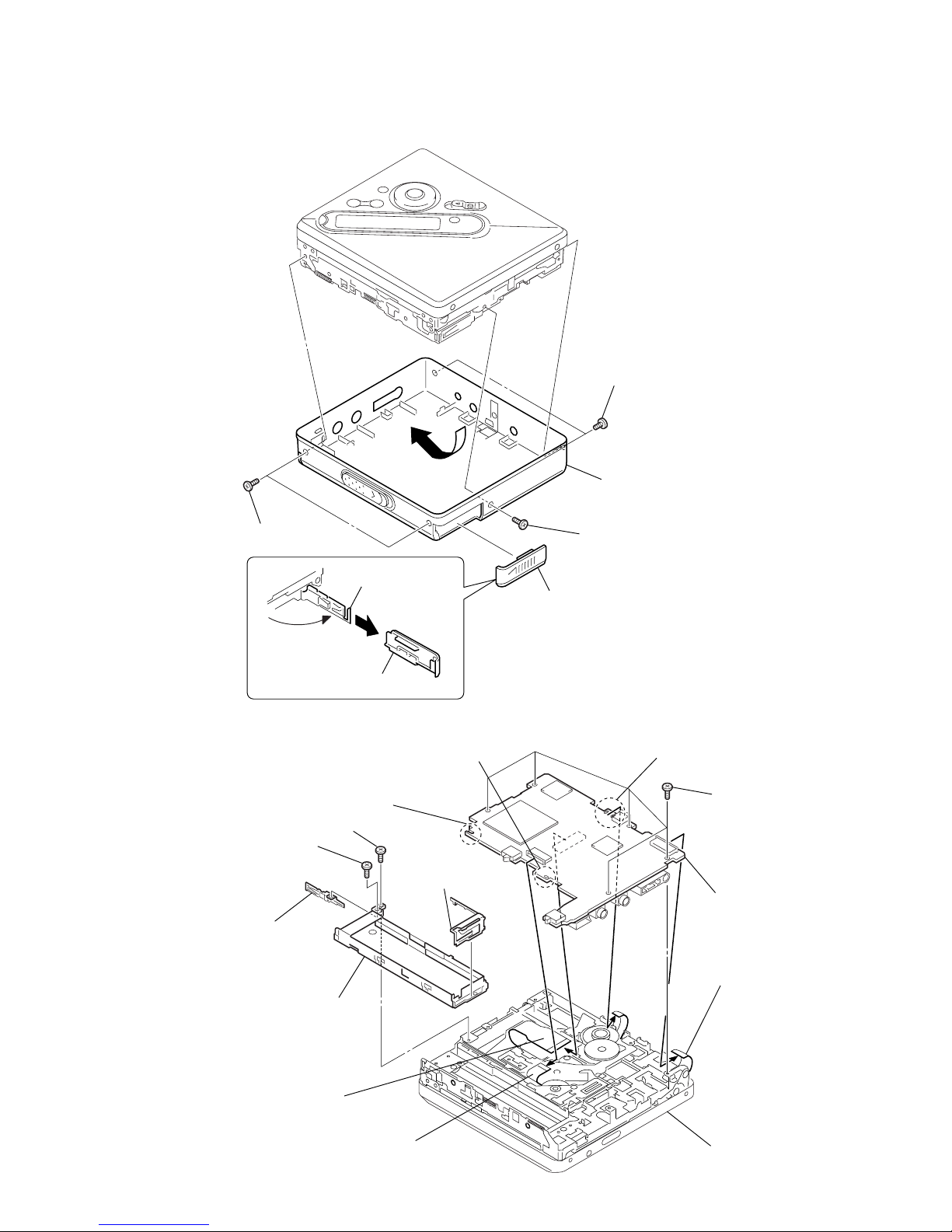
3-2. Case (Lower)
3-3. MAIN Board, Battery Case
4
two screws
(M1.4)
6
two screws
(M1.4)
5
screw
(M1.4)
3
Remove the battery
case lid.
battery lid
1
Open the battery
case lid.
2
claw
7
Remove the case (lower) in th
e
direction of the arrow.
6
five screws
(M1.4)
mechanism deck
(MT-MZN710-177)
7
flexible board (optical pick-up)
(CN501)
5
flexible board (motor)
(CN701)
3
Remove two solders of the
flexible board (over write head).
2
Remove the solder of
terminal (minus).
1
Remove the solder of
terminal (plus).
qd
battery case
qa
battery terminal (+)
9
screw (M1.4)
0
screw (M1.4)
qs
battery terminal
board (–)
8
main board
4
flexible board
(CN871)
8
MZ-NF810/NF810CK
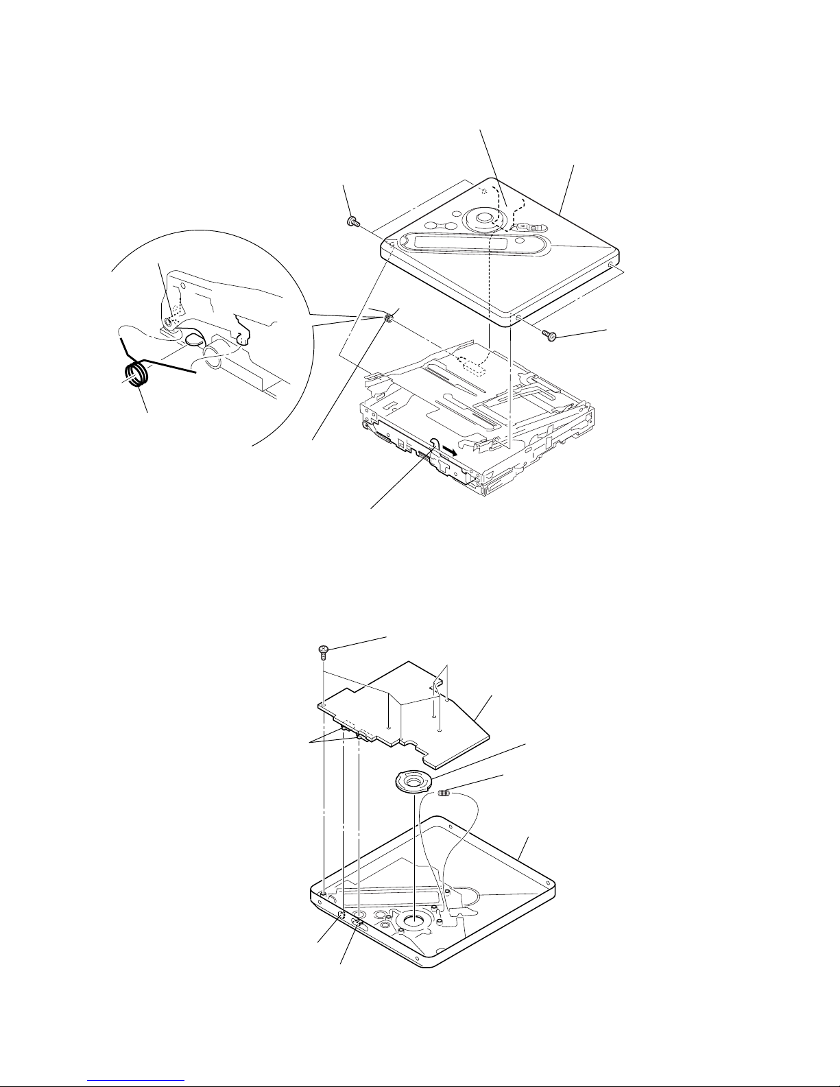
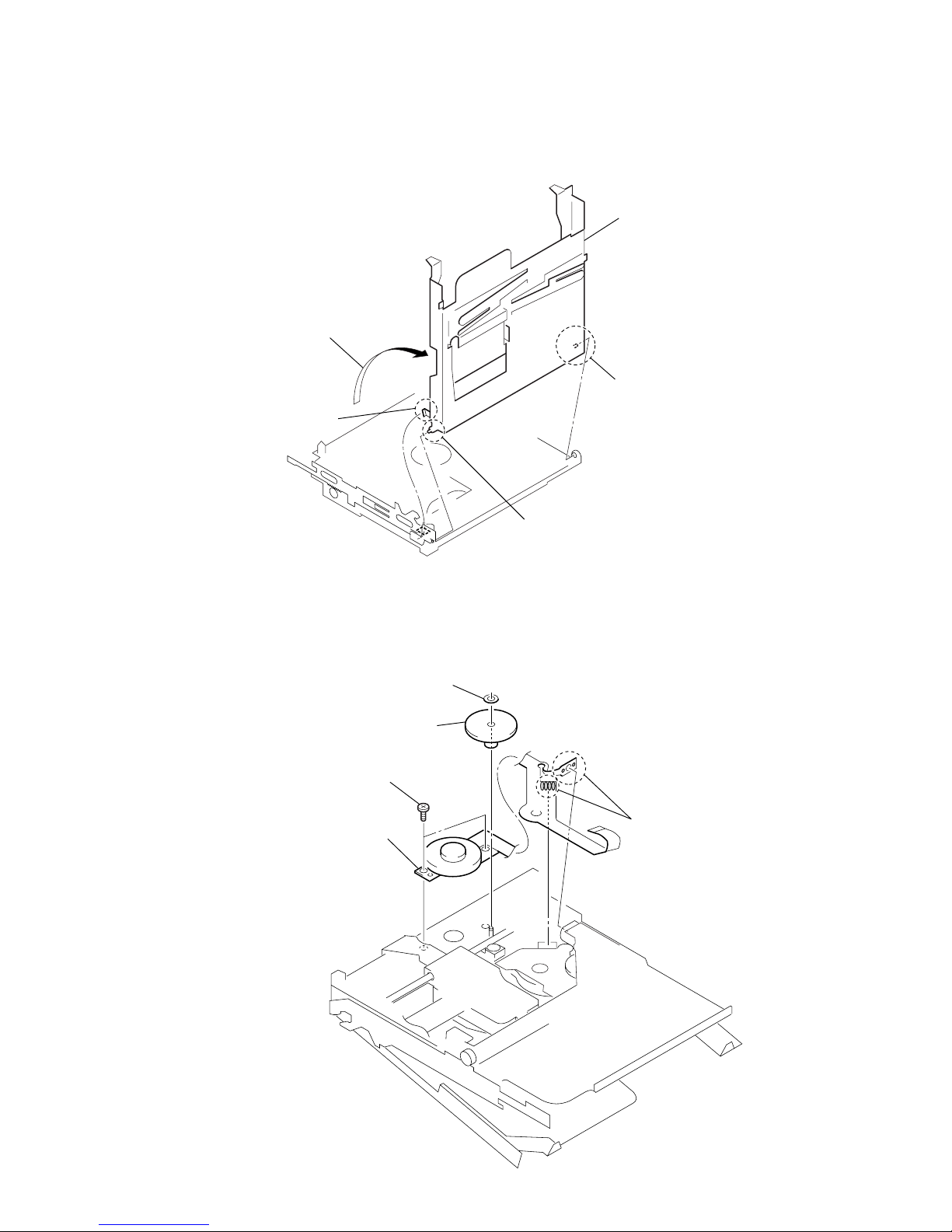
3-5. LCD Module, Panel Upper Block
3-4. Panel (Upper) Section
1
six screws
(1.7 × 2.5)
2
LCD module
4
spring (rec)
Note: On installation, adjust the position of
both switch and knob (hold), knob (t mark).
knob (hold)
button (t mark)
3
button (play
)
switch
5
upper panel block
3
two screws
(M1.4)
6
torsion spring
(pop up-L)
4
two screws
(M1.4)
2
Slide the open slider in the direction of the arrow,
and open the upper panel section.
set chassis assy
torsion spring (pop up-L)
1
flexible board
(CN871)
5
upper panel section
9
MZ-NF810/NF810CK
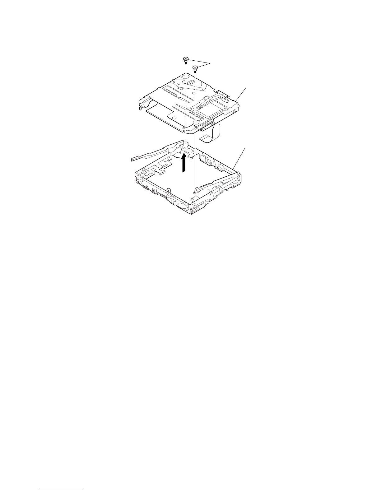
3-6. Mechanism Deck (MT-MZN710-177)
1
two step screws (MD)
4
set chassis assy
3
mechanism deck
(MT-MZN710-177)
2
10
MZ-NF810/NF810CK
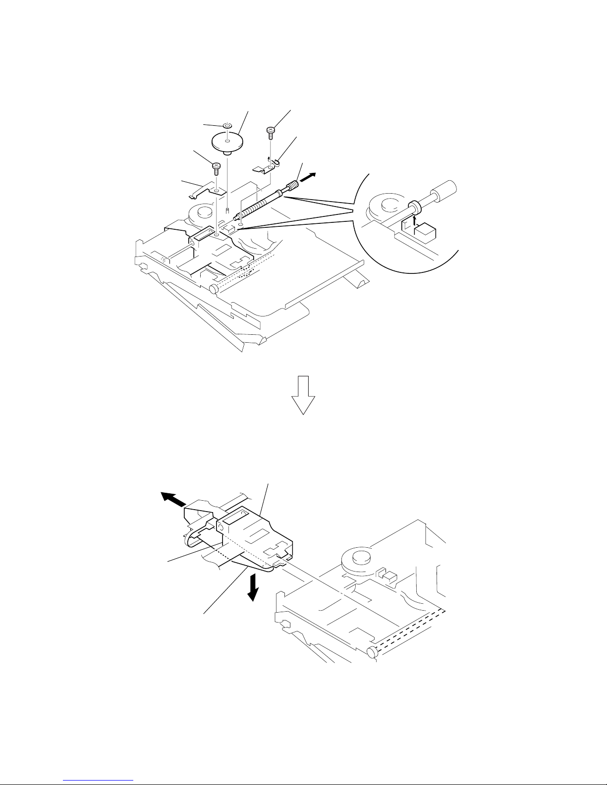
3-7. OP Ser vice Assy (LCX-5R)
4
rack spring
3
screw (M1.4)
1
washer (0.8-2.5)
2
gear (SA)
5
screw (M1.4)
6
thrust detent spring
8
Pull off lead screw.
7
over write head section
OP service assy (LCX-5R)
9
Opening the over write head
toward the direction
A
, remove the OP service assy
(LCX-5R) toward the direction
B
.
A
B
Note: Do not open the entire assy forcibly,
when opening the over write head.
11
MZ-NF810/NF810CK
3-9. DC Motor (Sled) (M602)
3-8. Holder Assy
4
holder ass
y
3
boss
3
boss
1
convex portion
2
Open the holder assy.
2
washer (0.8-2.5)
5
DC motor (sled) (M602)
4
two screws (M1.4)
3
gear (SA)
1
Remove six solders
of the motor flexible board.
12
MZ-NF810/NF810CK
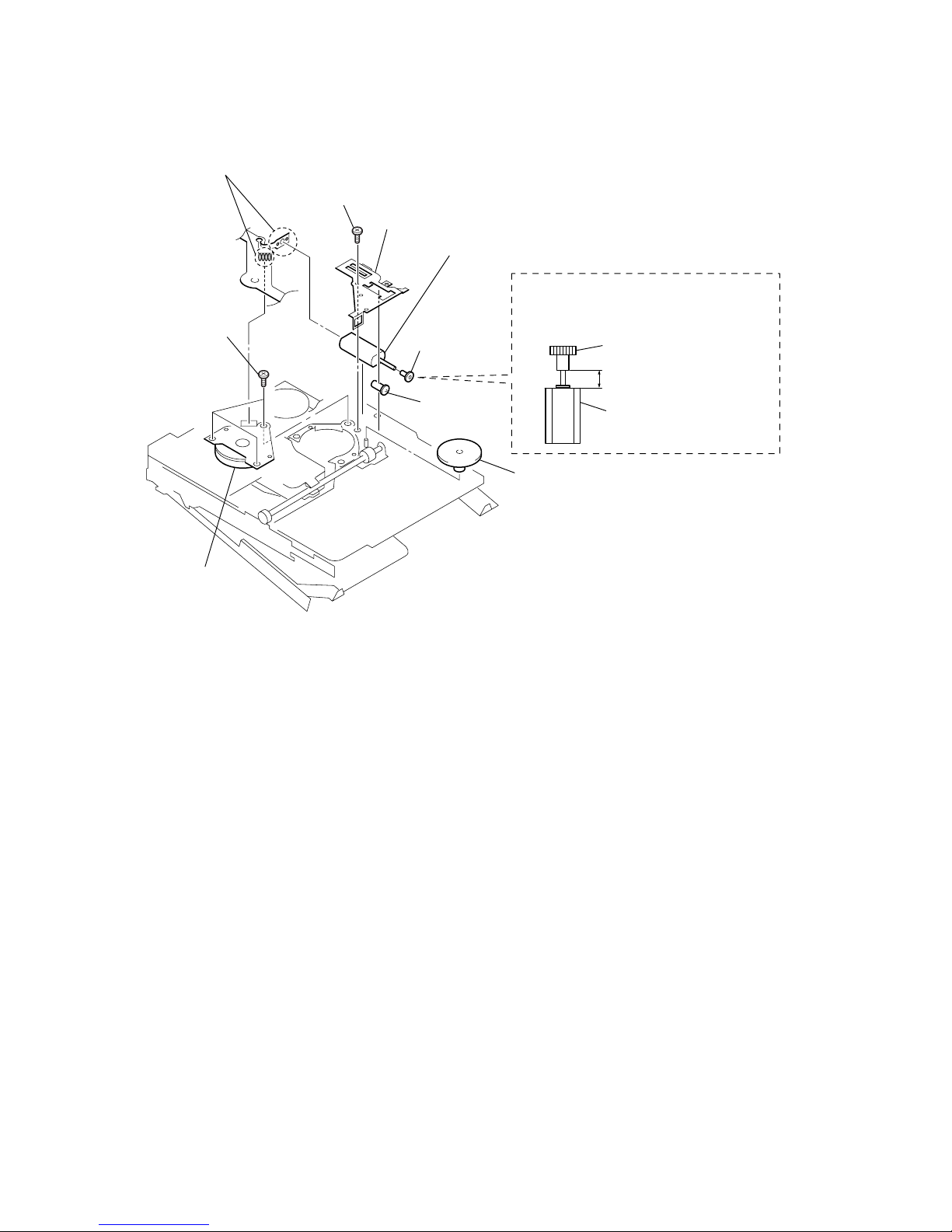
3-10. DC Motor (Over Write Head Up/Down) (M603), DC SSM18B Motor (Spindle) (M601)
9
DC SSM18B motor
(spindle) (M601)
8
three tapping screws
2
tapping screw
3
motor cover
6
gear (HA)
4
gear (HB)
5
gear (HC)
DC motor
(over write head up/down)
(M603)
3.15 mm
gear (HA)
Note: Press-fit the gear (HA) up to the position of
the DC motor (over write head up/down)
(M603) as shown below.
7
DC motor (over write head up/down)
(M603)
1
Remove six solders of the
motor flexible board.
13
MZ-NF810/NF810CK
Operation in Setting the Test Mode
•When the test mode becomes active, first the display check mode
is selected.
• Other mode can be selected from the display check mode.
•When the test mode is set, the LCD repeats the following display.
• When the
X key is pressed and hold down, the display at that
time is held so that display can be checked.
Releasing the Test Mode
For test mode set with the method 1:
Turn off the power and open the solder bridge on SL803 (TEST)
on the MAIN board.
Note: Remove the solders completely. Remaining could be shorted with
the chassis, etc.
For test mode set with the method 2 or 3:
Turn off the power.
2 In the normal mode, turn on the [HOLD] switch. While press-
ing the [GROUP] key press the following order:
t t t t t
t t t X t X
3 In the normal mode, turn on the [HOLD] switch on the set.
While pressing the xCANCEL/CHG key on the set, press
the keys on the remote commander with the following order:
N > t N > t . t . t N > t
. t N > t . t t
Note: If electrical adjustment (CD and MO overall adjustment) has not
been finished completely, “ERROR” is displayed on LCDs of the
set and the remote commander.
SECTION 4
TEST MODE
Outline
•This set provides the Overall adjustment mode that allows CD
and MO discs to be automatically adjusted when in the test mode.
In this overall adjustment mode, the disc is discriminated between CD and MO, and each adjustment is automatically executed in order. If a fault is found, the system displays its location. Also, the manual mode allows eac h indi vidual adjustment
to be automatically adjusted.
• Operation in the test mode is performed with the set. A key
having no particular description in the text, indicates a set key.
•For the LCD display, the LCD on the remote commander is
shown, but the contents of LCD display on the set are same.
Setting Method of Test Mode
There are three different methods to set the test mode:
1 Short SL803 (TEST) on the MAIN board with a solder bridge
(connect pin <zx. of IC801 to the ground) and turn on the power .
SL803
(TEST)
– MAIN Board (Side B) –
>
t
.
T
>
t
>
t
.
T
.T>
t
.
T
Microcomputer
version
display
All off
All lit
Remote commander LCD display
V1.500
006
Microcomputer
version
display
All off
All lit
Set LCD display
Ver 1.500
00
6
14
MZ-NF810/NF810CK
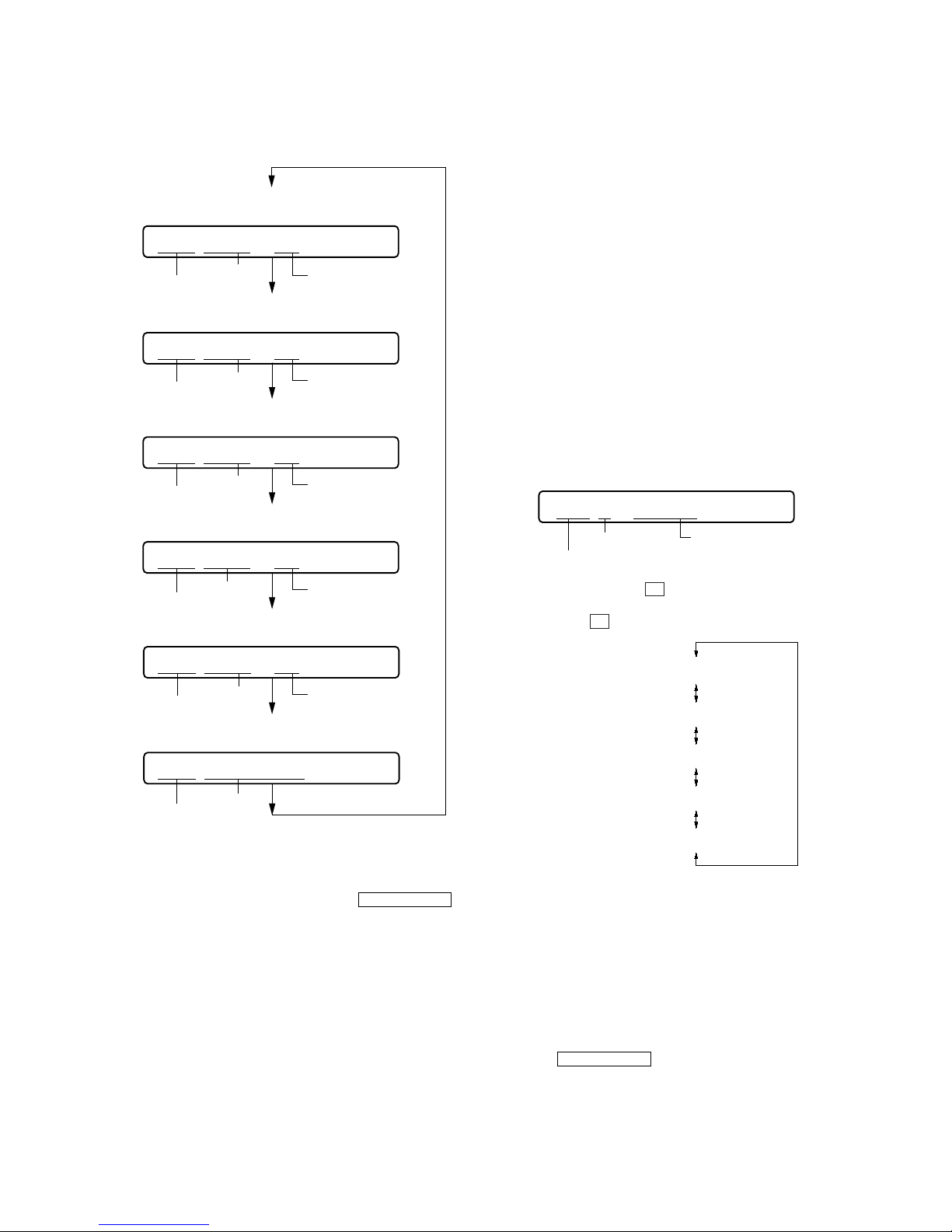
Configuration of Test Mode
Manual Mode
Mode to adjust or check the operation of the set by function.
Normally, the adjustment in this mode is not executed.
However, the Manual mode is used to clear the memory, power
supply adjustment, and laser power check before performing
automatic adjustments in the Overall Adjustment mode.
•Transition method in manual mode
1. Set the test mode (see page 13).
2. Press the or[VOL +] key activates the manual mode
where the LCD display as shown below.
3. During each test, the optical pick-up moves outward or inward while the or key is pressed for several seconds
respectively.
4. Each test item is assigned with a 3-digit item number;
100th place is a major item, 10th place is a medium item, and
unit place is a minor item.
The values adjusted in the test mode are written to the
nonvolatile memory (for the items where adjustment was
made).
Press the
xCANCEL/CHG
key
[Manual Mode]
[Servo Adjustment]
[Audio Adjustment]
[Power Supply Adjustment]
[OP Alignment Adjustment]
[Overall Adjustment Mode]
[Sound Skip Check Result Display Mode]
[Key Check Mode]
[Test Mode $Display Check Mode%]
Press the
xCANCEL/CHG
key
Press the
or
[VOL --]
key
Press the or
[REC]
key
Press the
or
[VOL +]
key
[Electrical Offset Adjustment]
Power Supply Adjustment
Auto Item Feed
CD Overall Adjustment/
MO Overall Adjustment
[Self-Diagnosis Result Display Mode]
Press the
[GROUP]
key
or press the
[DISPLAY]
key on the remote commander
Press the
[T MARK]
key, or
[DISPLAY]
key
on the remote commander for several
seconds (about 3 seconds)
The key check quits, or open the upper panel
Press the
xCANCEL/CHG
key
Press the
xCANCEL/CHG
key
>
.
N
ENTER
xCANCEL/CHG
key
xCANCEL/CHG
key
[VOL +] key: 100th place of item
number increase.
[VOL --] key: 100th place of item
number decrease.
[Major item switching]
[VOL +]
key: 10th place of item
number increase.
[VOL --] key: 10th place of item
number decrease.
[VOL +] key: Increases the adjusted
value of the 1st digit
[VOL --] key: Decreases the adjusted
value of the 1st digit
[Medium item switching]
key
[Minor item switching]
[Adjusted value variation]
X
key on the set or
key on the remote commander :
When adjusted value is changed:
Adjusted value is written.
When adjusted value is not changed:
That item is adjusted automatically.
[Adjusted value write]
key:Unit place of item number
increase.
key:Unit place of item number
decrease.
[P MODE] key of
the remote commander:
Increase the adjusted value
of the 2nd digit
[SOUND] key of the remote commander:
Decrease the adjusted value
of the 2nd digit
>
key
>
>
.
Remote commander LCD display
Manual
000
>
t
>t.
T
15
MZ-NF810/NF810CK
Self-Diagnosis Result Display Mode
This set uses the self-diagnostic function system in which if an
error occurred during the recording or playing, the mechanism
control block and the power supply control block in the
microcomputer detect it and record its cause as history in the
nonvolatile memory.
By checking this history in the test mode, you can analyze a fault
and determine its location.
Total recording time is recorded as a guideline of how long the
optical pick-up has been used, and by comparing it with the total
recording time at the time when an error occurred in the selfdiagnosis result display mode, you can determine when the error
occurred.
Clear both self-diagnosis history data and total recording time, if
the optical pick-up was replaced.
• Self-diagnosis result display mode setting method
1. Set the test mode (see page 13).
2. In the display check mode, press the [GROUP] key or press
the [DISPLAY] key on the remote commander activates the
self-diagnosis result display mode where the LCD display as
shown below.
3. Then, each time the key is pressed, LCD display descends
by one as shown below. Also, the LCD display ascends by one
when the key is pressed.
If the
[GROUP] key is pressed or the [DISPLAY] key on remote
commander is pressed with this display, the LCD switches to the
simple display mode.
4. Quit the self-diagnosis result display mode, and press
the xCANCEL/CHG key to return to the test mode (display
check mode).
5. The display changes a shown below each time the [END
SEARCH] is pressed or the [DISPLAY] key on the remote
commander is pressed.
However in the power mode (item number 700’s), only the
item is displayed.
6. Quit the manual mode, and press the
xCANCEL/CHG key to
return to the test mode (display check mode).
Overall Adjustment Mode
Mode to adjust the servo automatically in all items.
Normally, automatic adjustment is executed in this mode at the
repair.
For further information, refer to “SECTION 5 ELECTRICAL
ADJUSTMENTS” (see page 18).
item number
address
adjusted value
item number
jitter value
adjusted value
item number
block error
value
adjusted value
item number
ADIP error
value
Focus drive
value
adjusted value
item number
adjusted value
item number
item title
• Address & Adjusted Value Display
Remote commander LCD display
• Jitter Value & Adjusted Value Display
Remote commander LCD display
C68S01
011
• Block Error Value & Adjusted Value Display
Remote commander LCD display
• ADIP Error Value & Adjusted Value Display
Remote commander LCD display
• Focus Drive Value & Adjusted Value Display
Remote commander LCD display
• Item Title Display
Remote commander LCD display
063B01
011
059A01
011
015F01
011
OFFJ01
011
LrefPw
011
Remote commander LCD display
history code
Total recording time
when error occurred
error display code
1 0000
0XX
0XX 1 ****
0XX N ****
0XX N1****
0XX N2****
0XX R_****
XX : Error code
**** : Total recording time
>
t
.
T
16
MZ-NF810/NF810CK
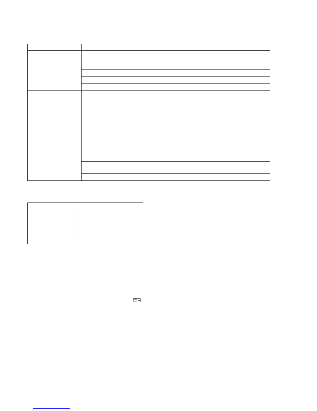
• Description of indication history
History code number Description
1The first error
N The last error
N1 One error before the last.
N2 Two errors before the last.
R_ Total recording time
Reset the Error Display Code
After servicing, reset the error display code.
• Setting method of reset the error display code
1. Set the test mode (see page 13).
2. Pressing the [GROUP] key or pressing the [DISPLAY] key on
the remote commander activates the self-diagnosis result display mode.
3. To reset the error display code, press the [REC] key or
key on the remote commander (twice) when the code is displayed (except “R_****”).
(All the data on the 1, N, N1, and N2 will be reset)
• Description of error indication codes
Problem Indication code Meaning of code Simple display Description
No error 00 No error --- No error
01
Illegal access target
Adrs Attempt to access an abnormal address
address was specified
Servo system error 02 High temperature Temp High temperature detected
03 Focus error Fcus Disordered focus or can not read an address
04 Spindle error Spdl Abnormal rotation of disc
TOC error
11 TOC error TOC Faulty TOC contents
12 Data reading error Data Data could not be read at SYNC
13 TOC address error Tadr TOC address data error
Power supply system error 22 Low battery LBat Momentary interruption detected
31 Offset error Ofst Offset error
32
Focus error ABCD
ABCD Focus error ABCD offset error
offset error
33
Tracking error
TE Tracking error Offset error
Offset system error Offset error
34
X1 tracking error
X1TE X1 tracking error Offset error
Offset error
35
MD DATA 2
MD2 MD DATA 2 disc error
disc error
36 Mirror error Mirr Mirror retry over

17
MZ-NF810/NF810CK
Key Check Mode
This set can check if the set and remote commander function normally.
• Setting method of key check mode
1. Set the test mode (see page 13).
2. Pressing the [T MARK] key or [DISPLAY] key on the remote
commander for several seconds (about 3 seconds) activates the
key check mode. (At the last two digits, AD value of remote commander key line is displayed in hexadecimal)
3. When each key on the set and on remote commander is pressed,
its name is displayed on the remote commander LCD. (The
operated position is displayed for 4 seconds after the slide
switch is operated. If any other key is pressed during this display, the remote commander LCD switches to its name display)
Example1: When the key on the set is pressed:
Example2: When the
NX/ENT key on the remote com-
mander is pressed:
4. When all the keys on the set and on the remote commander are
considered as OK, the following displays are shown.
Example1: When the keys on the set are considered as OK:
Example2: When the keys on the remote commander are con-
sidered as OK:
5. When all keys were checked or if the upper panel is opened,
the key check mode quits and the test mode (display check
mode) comes back.
Sound Skip Check Result Display Mode
This set can display the count of errors that occurred during the
recording/playing for checking.
• Setting method of sound skip check result display
mode
1. Set the test mode (see page 13).
2. Press the key or [REC] key, and the playing or recording
sound skip result display mode becomes active respectively
where the LCD displays the following.
3. When the key is pressed, total error count is displayed on
the LCD, and each time the key is pressed, the display
item moves down by one as shown below. Also, if the key
is pressed, the display item moves up by one, then if the [REC]
key is pressed, the display in the record mode appears.
When the [REC] key is pressed, total error count is displayed
on the LCD, and each time the key is pressed, the display item moves down by one as shown below. Also, if the
key is pressed, the display item moves up by one, then if
the key is pressed, the display in the play mode appears.
• Cause of sound skip error
Cause of error Description of error
EIB Sound error correction error
Play
Stat Decoder status error
Adrs Address access error
BEmp Buffer is empty
BOvr
Buffer is full, and sounds were
dumped
Record
Bful
Buffer capacity becomes less,
and forcible writing occurred
Rtry Retry times over
4. To quit the sound skip check result display mode and to return
to the test mode (display check mode), press the xCANCEL/
CHG key.
Remote commander LCD display
Total count of play
system errors (hex.)
Total count of record
system errors (hex.)
P**R**
000
000 P**R**
000 EIB **
000 Stat**
000 Adrs**
000 BEmp**
000 ######
000 P**R**
000 BOvr**
000 Bful**
000 Rtry**
000 ######
P**R**
: Total play/record errors (hex.)
**
: Counter of sound skip check each item (hex.)
######
: 6-digit address where sound was skipped last (hex.)
Playing sound skip
result display
Recording sound skip
result display
Remote commander LCD display
**
000
**
: AD value of the remote commander key
(hexadecimal 00 to FF)
N
ENTER
>
t
.
T
N
ENTER
.
T
>
t
N
ENTER
>
t
Remote commander LCD display
**
: AD value of the remote commander key
(hexadecimal 00 to FF)
FF **
000
Remote commander LCD display
**
: AD value of the remote commander key
(hexadecimal 00 to FF)
rP PUS **
000
Remote commander LCD display
**
: AD value of the remote commander key
(hexadecimal 00 to FF)
SET OK **
888
Remote commander LCD display
**
: AD value of the remote commander key
(hexadecimal 00 to FF)
RMC OK **
888
18
MZ-NF810/NF810CK
Outline
• In this set, automatic adjustment of CD and MO can be performed by entering the test mode.
However, before starting automatic adjustment, the memory
clear, power supply adjustment, and laser power check must be
performed in the manual mode.
•A key having no particular description in the text, indicates a
set key.
•For the LCD display, the LCD on the remote commander is
shown, but the contents of LCD display on the set are same.
Precautions for Adjustment
1. Adjustment must be done in the test mode only.
After adjusting, release the test mode.
2. Use the following tools and measuring instruments.
•Test CD disc TDYS-1
(Part No. : 4-963-646-01)
• SONY MO disc available on the market
• Digital voltmeter
• Laser power meter LPM-8001
(Part No. : J-2501-046-A)
•Thermometer (using the Temperature Correction)
• Personal computer
• USB cable
3. Unless specified otherwise, supply DC 3V from the DC IN
3V jack (J951).
4. Switch position
HOLD switch ............................................... ON
Adjustment Sequence
1. NV Reset (item number: 021)
(EEPROM clear)
r
2. Temperature Correction (item number: 015)
Manual Mode
r
3. Power Supply Manual Adjustment
r
4. Laser Power Check
r
5. CD Overall Adjustment (item number: 031)
r
Overall Mode
6.
MO
Overall Adjustment (item number: 034)
r
7. RESUME Clear (item number 043)
r
Manual Mode
8. Rewriting the Patch Data
(at replacement of the MAIN board)
r
9. Rewriting the NV values
2. Press the
X key.
3. Press the X key once more.
4. Press the xCANCEL/CHG key to quit the manual mode, and
return to the test mode (display check mode).
Temparature Correction
• Adjustment Method of Temperature Correction
1. Select the manual mode of the test mode, and set the item number 015 (see page 14).
2. Measure the ambient temperature.
3. Adjust with [VOL +] or [VOL --] key so that the adjusted value
(hexadecimal value) becomes the ambient temperature.
(Initial value : 19h = 25˚C, Adjusting range : 80h to 7fh
(–128˚C to +127˚C))
4.
Press the Xkey or press the key on the remote commander
to write the adjusted value.
Power Supply Manual Adjustment
• Adjustment sequence
Adjustment must be done with the following steps.
1. VC1_LOW (PB) adjustment (item number : 741)
2. VC1_HIGH (REC) adjustment (item number : 742)
3. VC2_LOW adjustment (item number : 743)
4. VC2_HIGH adjustment (item number : 744)
5. REG1 adjustment (item number : 745)
6. REG3_LOW1 adjustment (item number : 747)
7. REG3_LOW2 adjustment (item number : 748)
8. REG3_HIGH adjustment (item number : 749)
9. VREC_LOW (X2 speed) adjustment (item number : 751)
10. VREC_MIDDLE (X4 speed)adjustment (item number : 752)
11. VREC_HIGH (HEAD MOTOR) adjustment (item number : 753)
12. CHGV_LOW adjustment (item number : 755)
13. CHGV_HIGH adjustment (item number : 756)
14. CHGI_LOW (current) adjustment (item number : 757)
15. CHGI_HIGH (current) adjustment (item number : 758)
• Setting Method of Power Supply Manual Adjustment
1. Make sure that the power supply voltage is 3V.
2. Select the manual mode of the test mode (see page 14).
3. Set item number.
Note: Power supply adjustment auto item feed mode (page 23) is
available to perform the temperature Correction and Power
Supply Adjustment without entering the manual mode.
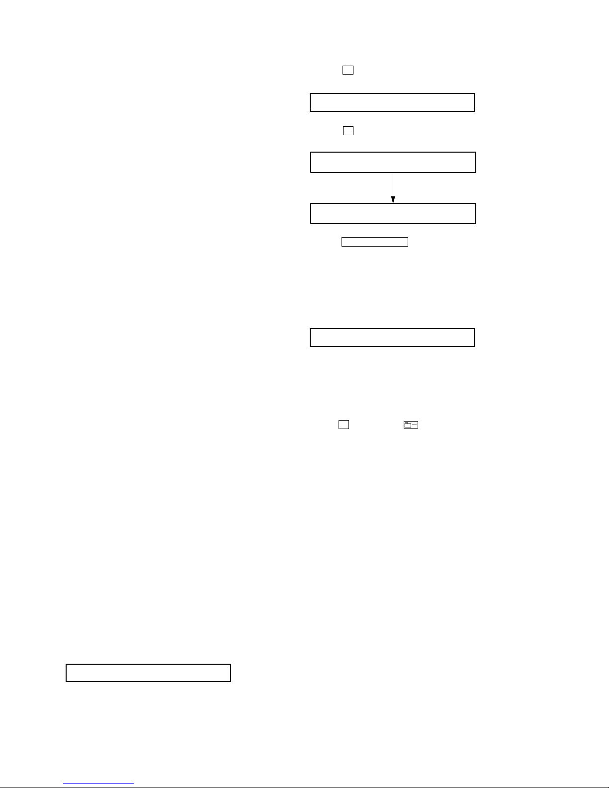
NV Reset
• Setting Method of NV Reset
1. Select the manual mode of the test mode, and set item number
021 NV Reset (see page 14).
SECTION 5
ELECTRICAL ADJUSTMENTS
Remote commander LCD display
Res***
021
Reset!
021
NV reset (after several seconds)
021 ResNV CC
Remote commander LCD display
021 ResOK?
Remote commander LCD display
015 SetTmp **
Remote commander LCD display
**
: Adjusted value
19
MZ-NF810/NF810CK
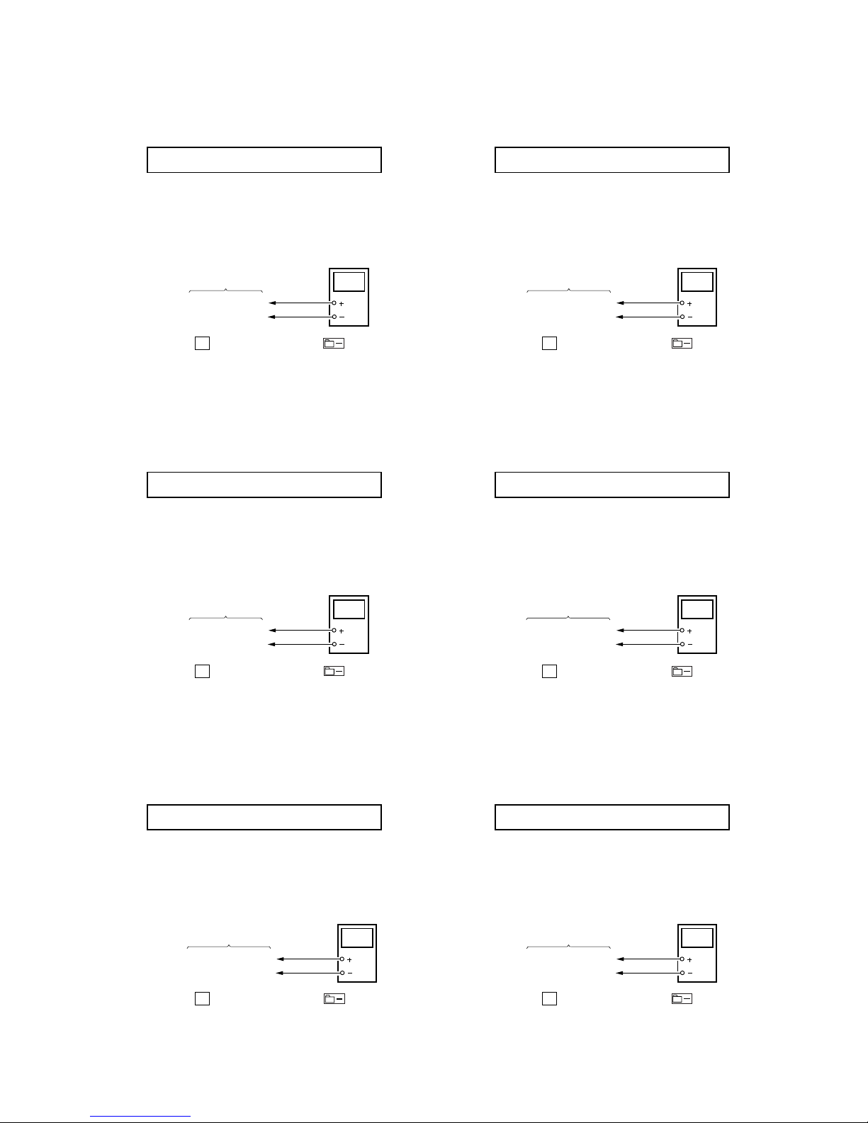
• Adjustment Method of VC2_HIGH
(item number: 744)
1. Connect a digital voltmeter to the TP1905 (VCOUT) on the
MAIN board, and adjust
[VOL +] key (voltage up) or [VOL --]
key (voltage down) so that the voltage becomes 2.55 ± 0.01V.
2. Press the
X key on the set or the key on the remote
commander to write the adjusted value.
Adjustment and Connection Location:MAIN board
(see page 22)
• Adjustment Method of REG1
(item number: 745)
1. Connect a digital voltmeter to the TP1909 (REGO1) on the
MAIN board, and adjust [VOL +] key (voltage up) or [VOL --]
key (voltage down) so that the voltage becomes 2.05 ± 0.01V.
2. Press the X key on the set or the key on the remote
commander to write the adjusted value.
Adjustment and Connection Location:MAIN board
(see page 22)
• Adjustment Method of REG3_LOW1 (H)
(item number: 747)
1. Connect a digital voltmeter to the TP1907 (REGO3) on the
MAIN board, and adjust
[VOL +] key (voltage up) or [VOL --]
key (voltage down) so that the voltage becomes 1.25 ± 0.01V.
2. Press the X key on the set or the key on the remote
commander to write the adjusted value.
Adjustment and Connection Location:MAIN board
(see page 22)
• Adjustment Method of VC1_LOW (PB)
(item number: 741)
1. Connect a digital voltmeter to the TP1928 (VCO1) on the MAIN
board, and adjust
[VOL +] key (voltage up) or [VOL --] key (volt-
age down) so that the voltage becomes 2.35 ± 0.05V.
2. Press the
X key on the set or the key on the remote
commander to write the adjusted value.
Adjustment and Connection Location:MAIN board
(see page 22)
• Adjustment Method of VC1_HIGH (REC)
(item number: 742)
1. Connect a digital voltmeter to the TP1928 (VCO1) on the
MAIN board, and adjust [VOL +] key (voltage up) or [VOL --]
key (voltage down) so that the voltage becomes 2.75 ± 0.05V.
2. Press the X key on the set or the key on the remote
commander to write the adjusted value.
Adjustment and Connection Location:MAIN board
(see page 22)
• Adjustment Method of VC2_LOW
(item number: 743)
1. Connect a digital voltmeter to the TP1905 (VCOUT) on the
MAIN board, and adjust
[VOL +] key (voltage up) or [VOL --]
key (voltage down) so that the voltage becomes 2.30 ± 0.01V.
2. Press the X key on the set or the key on the remote
commander to write the adjusted value.
Adjustment and Connection Location:MAIN board
(see page 22)
digital
voltmete
r
MAIN board
TP1928 (VCO1)
BATT– (GND)
digital
voltmete
r
TP1905 (VCOUT)
BATT– (GND)
MAIN board
digital
voltmete
r
MAIN board
TP1928 (VCO1)
BATT– (GND)
digital
voltmete
r
TP1905 (VCOUT)
BATT– (GND)
MAIN board
digital
voltmete
r
TP1909 (REGO1)
BATT– (GND)
MAIN board
digital
voltmete
r
TP1907 (REGO3)
BATT– (GND)
MAIN board
741 VC1 L **
**
: Adjusted value
Remote commander LCD display
742 VC1 H **
**
: Adjusted value
Remote commander LCD display
743 VC2 Lo **
**
: Adjusted value
Remote commander LCD display
744 VC2 Hi **
**
: Adjusted value
Remote commander LCD display
745 REG1 **
**
: Adjusted value
Remote commander LCD display
747 REG3L1 **
**
: Adjusted value
Remote commander LCD display
20
MZ-NF810/NF810CK
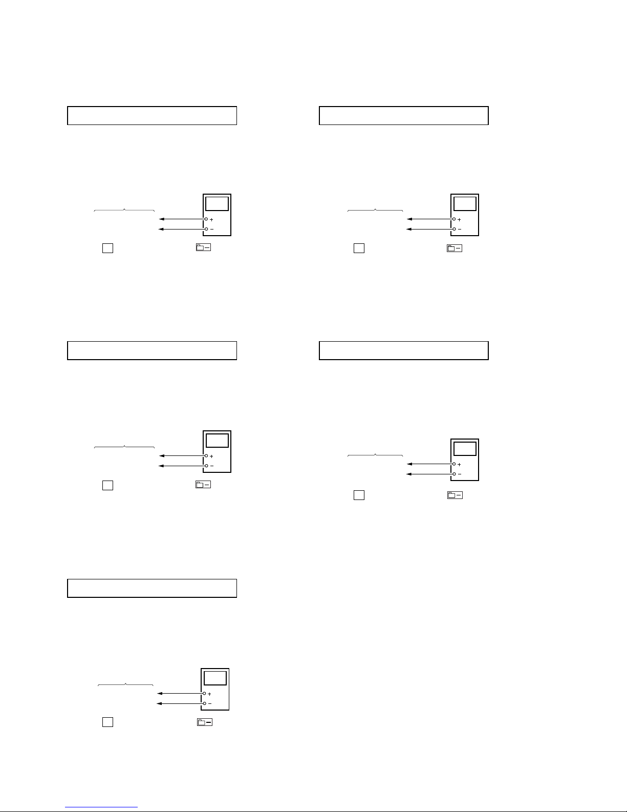
• Adjustment Method of REG3_LOW2
(item number: 748)
1. Connect a digital voltmeter to the TP1907 (REGO3) on the
MAIN board, and adjust
[VOL +] key (voltage up) or [VOL --]
key (voltage down) so that the voltage becomes 1.25 ± 0.01V.
2. Press the
X key on the set or the key on the remote
commander to write the adjusted value.
Adjustment and Connection Location:MAIN board
(see page 22)
• Adjustment Method of REG3_HIGH
(item number: 749)
1. Connect a digital voltmeter to the TP1907 (REGO3) on the
MAIN board, and adjust [VOL +] key (voltage up) or [VOL --]
key (voltage down) so that the voltage becomes 1.25 ± 0.01V.
2. Press the X key on the set or the key on the remote
commander to write the adjusted value.
Adjustment and Connection Location:MAIN board
(see page 22)
• Adjustment Method of VREC_LOW (X2 speed)
(item number: 751)
1. Connect a digital voltmeter to the TP1620 (VREC) on the MAIN
board, and adjust
[VOL +] key (voltage up) or [VOL --] key
(voltage down) so that the voltage becomes 1.10 ± 0.02V.
2. Press the
X key on the set or the key on the remote
commander to write the adjusted value.
Adjustment and Connection Location:MAIN board
(see page 22)
• Adjustment Method of VREC_MIDDLE (X4 speed)
(item number: 752)
1. Connect a digital voltmeter to the TP1620 (VREC) on the MAIN
board, and adjust
[VOL +] key (voltage up) or [VOL --] key
(voltage down) so that the voltage becomes 1.10 ± 0.02V.
2. Press the
X key on the set or the key on the remote
commander to write the adjusted value.
Adjustment and Connection Location:MAIN board
(see page 22)
• Adjustment Method of VREC_HIGH (HEAD MOTOR)
(item number: 753)
1. Connect a digital voltmeter to the TP1620 (VREC) on the MAIN
board, and adjust [VOL +] key (voltage up) or [VOL --] key
(voltage down) so that the voltage becomes between 1.65V and
1.75V.
2. Press the
X key on the set or the key on the remote
commander to write the adjusted value.
Adjustment and Connection Location:MAIN board
(see page 22)
digital
voltmete
r
TP1907 (REGO3)
BATT– (GND)
MAIN board
digital
voltmete
r
TP1907 (REGO3)
BATT– (GND)
MAIN board
748 REG3L2 **
**
: Adjusted value
Remote commander LCD display
749 REG3 H **
**
: Adjusted value
Remote commander LCD display
751 VREC L **
**
: Adjusted value
Remote commander LCD display
digital
voltmete
r
TP1620 (VREC)
BATT– (GND)
MAIN board
752 VREC M **
**
: Adjusted value
Remote commander LCD display
digital
voltmete
r
TP1620 (VREC)
BATT– (GND)
MAIN board
753 VREC H **
**
: Adjusted value
Remote commander LCD display
digital
voltmete
r
TP1620 (VREC)
BATT– (GND)
MAIN board
21
MZ-NF810/NF810CK
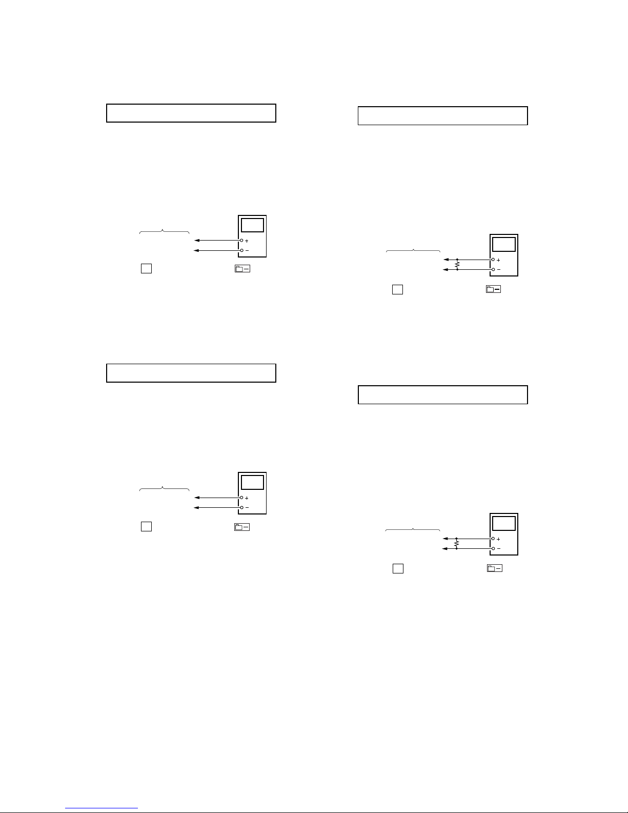
• Adjustment Method of CHGV_LOW
(item number: 755)
Note: Remove the rechargeable battery.
1. Connect a digital voltmeter to the BATT+ on the MAIN board,
and adjust
[VOL +] key (voltage up) or [VOL --] key (voltage
down) so that the voltage becomes 1.35 ± 0.01V.
2. Press the
X key on the set or the key on the remote
commander to write the adjusted value.
Adjustment and Connection Location:MAIN board
(see page 22)
• Adjustment Method of CHGV_HIGH
(item number: 756)
Note: Remove the rechargeable battery.
1. Connect a digital voltmeter to the BATT + on the MAIN board,
and adjust
[VOL +] key (voltage up) or [VOL --] key (voltage
down) so that the voltage becomes 1.80 ± 0.015V.
2. Press the
X key on the set or the key on the remote
commander to write the adjusted value.
Adjustment and Connection Location:MAIN board
(see page 22)
• Adjustment Method of CHGI_LOW (Charge Current)
(item number: 757)
Note: Remove the rechargeable battery.
Connect the resistor (47 ) (0.5%) between terminals of
BATT + and BATT –.
1. Connect a digital voltmeter to the BATT + on the MAIN board,
and adjust
[VOL +] key (voltage up) or [VOL --] key (voltage
down) so that the voltage becomes 1.41 ± 0.015V.
2. Press the
X key on the set or the key on the remote
commander to write the adjusted value.
Adjustment and Connection Location:MAIN board
(see page 22)
• Adjustment Method of CHGI_HIGH (Charge Current)
(item number: 758)
Note: Remove the rechargeable battery.
Connect the resistor (10 ) (0.5%) between terminals of
BATT + and BATT –.
1. Connect a digital voltmeter to the BATT + on the MAIN board,
and adjust [VOL +] key (voltage up) or [VOL --] key (voltage
down) so that the voltage becomes 1.40 ± 0.015V.
2. Press the
X key on the set or the key on the remote
commander to write the adjusted value.
Adjustment and Connection Location:MAIN board
(see page 22)
digital
voltmete
r
BATT + (W902)
BATT – (GND)
MAIN board
10
Ω
(0.5%)
756 ChgV H **
**
: Adjusted value
Remote commander LCD display
digital
voltmete
r
BATT +(W902)
BATT – (GND)
MAIN board
757 CIL **
**
: Adjusted value
Remote commander LCD display
digital
voltmete
r
BATT + (W902)
BATT – (GND)
MAIN board
47
Ω
(0.5%)
758 CIH **
**
: Adjusted value
Remote commander LCD display
755 ChgV L **
**
: Adjusted value
Remote commander LCD display
digital
voltmete
r
BATT +(W902)
BATT – (GND)
MAIN board
 Loading...