

Page 1

Switcher System
MVS-8000/8000SF System (With CCP-8000 Series)
Multi Format
Multi Format
Switcher System
MVS-8000/8000SF System
(With CCP-8000 Series Center Control Panel)
User’s Guide
Volume 1
2nd Edition (Revised 1)
[ English ]
User’s Guide [English]
Volume 1
2nd Edition (Revised 1)
3-206-016-12 (1)
Page 2

MVS-8000/8000SF System
(With CCP-8000 Series Center Control Panel)
User’s Guide
Multi Format Switcher System
Volume 1 [English]
2nd Edition (Revised 1)
Software Version 7.20 and Later
Page 3

NOTICE TO USERS
© 2001 Sony Corporation. All rights reserved. This
manual or the software described herein, in whole or in
part, may not be reproduced, translated or reduced to
any machine readable form without prior written approval
from Sony Corporation.
SONY CORPORATION PROVIDES NO WARRANTY
WITH REGARD TO THIS MANUAL, THE SOFTWARE
OR OTHER INFORMATION CONTAINED HEREIN AND
HEREBY EXPRESSLY DISCLAIMS ANY IMPLIED
WARRANTIES OF MERCHANTABILITY OR FITNESS
FOR ANY PARTICULAR PURPOSE WITH REGARD TO
THIS MANUAL, THE SOFTWARE OR SUCH OTHER
INFORMATION. IN NO EVENT SHALL SONY
CORPORATION BE LIABLE FOR ANY INCIDENTAL,
CONSEQUENTIAL OR SPECIAL DAMAGES,
WHETHER BASED ON TORT, CONTRACT, OR
OTHERWISE, ARISING OUT OF OR IN CONNECTION
WITH THIS MANUAL, THE SOFTWARE OR OTHER
INFORMATION CONTAINED HEREIN OR THE USE
THEREOF.
Sony Corporation reserves the right to make any
modification to this manual or the information contained
herein at any time without notice.
The software described herein may also be governed by
the terms of a separate user license agreement.
Page 4

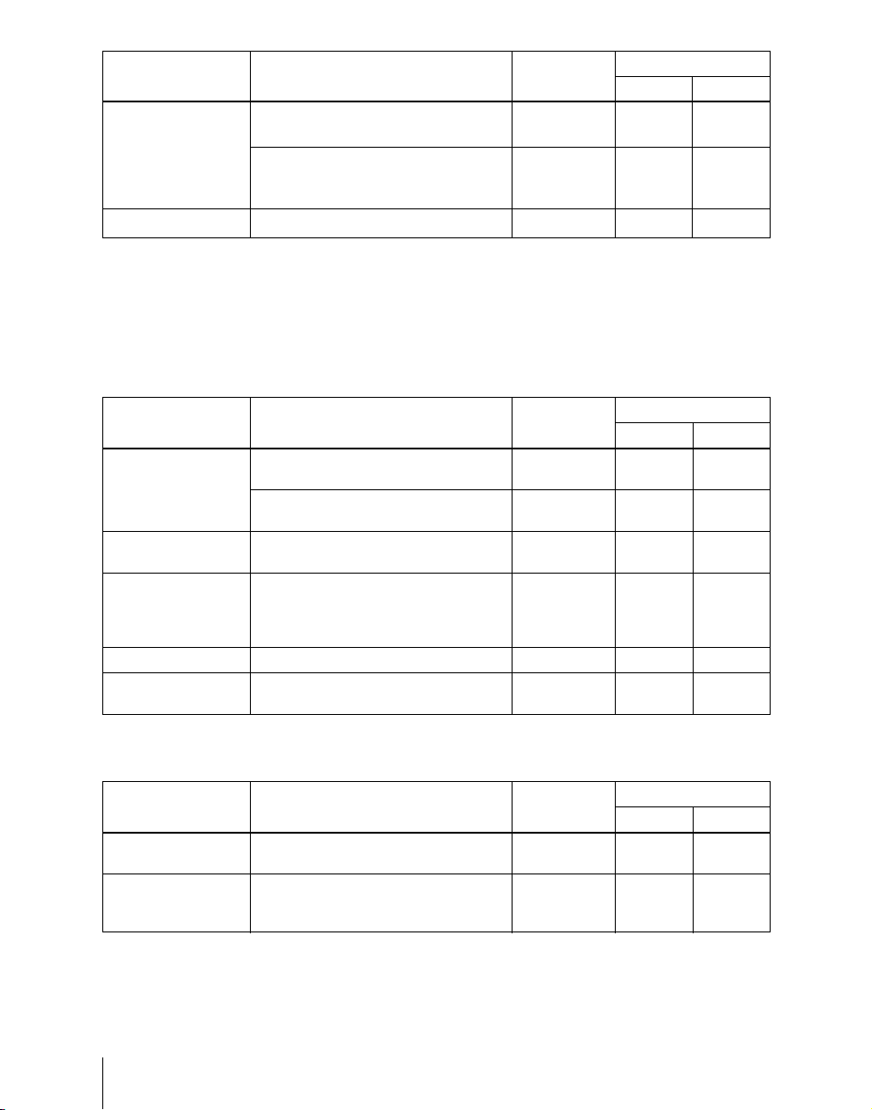
Functions Newly Supported in Version 7.20
The functions newly supported in the MVS-8000 system version 7.20 are as
follows.
Functions relating to switcher processor
Classification Functions supported Menu No. See page
Vol. 1 Vol. 2
System 1080P/59.94 and 1080P/50 formats
and dual link support
Transition Preset color mix with an image
Key Fixing key fill and key source in key
Frame memory
DME Applying DME effects to a maximum of
Files
Macros Creating and editing macro timelines 5441, 5441.1 216 546
Color corrector All the internal signals of the switcher
selected on the utility 2 bus in place of
a color matte
drop off mode (frame delay mode)
Clip transition
Recording and playback of ancillary
b)
data
Recording and recalling of extended
d)
clip
three keys on the SDI interface in
combination with a dedicated
interface
• File operations of extended clips
• Converting between frame memory
• Importing extended clips
Macro take operation using a GPI input 7325.1, 7352 - 369, 436
Setting a macro attachment without
changing cross-points
Recalling frame memory clips - 212 -
Recording with external devices - 212 -
Changing the registers for saving
macros
can be selected for color correction
b)
clips and extended clips
a)
b)
b)
d)
d)
7313 245 -
1171 342 -
1112.4 55, 393 -
c)
1176.1 42, 93 -
2525, 7316.8 92 314
2521, 2522,
2523
7337.7 - 423
d)
7151, 7151.1,
7162
7326.6 - 381, 530
7142.3 - 502
7335 - 410
c)
87 -
205 468, 476,
482
3
Page 5
Classification Functions supported Menu No. See page
Vol. 1 Vol. 2
Multi program 2 Re-entry between the main and sub
sides of the same M/E bank
When recalling snapshot, keys on main
Diagnosis
or sub side can be recalled
independently.
Displaying communication status
a) For MVS-8000G only
b) For other than MVS-8000
c) For MVS-8000G/8000GSF only
d) For MVS-8000A or MVS-8000G only
b)
b)
7331 240 -
- 239 -
b)
7431 - 567
Functions relating to operability
Classification Functions supported Menu No. See page
Vol. 1 Vol. 2
Control panel Inhibiting cross-point button operations 7321.12,
Distinguishable color of the shifted
button numbers in the Xpt Assign menu
External devices Making the USB primary setting
automatic
Macros Holding down [PRE MCRO] and [POST
MCRO] buttons together makes it
possible to set a macro attachment in
macro only mode
Files 40 or more directories can be created 71xx - 485
Snapshot Wipe and DME wipe snapshot
operations with menu
7324
7322.x1 - 346
7317 - 316
- 218, 259 531
1157, 1167 182 -
31 334
Functions relating to external devices
Classification Functions supported Menu No. See page
Audio mixer Selection of signals linked with the
audio mixer
GPI output Addition of “Device Recording” to the
actions triggered by control panel or
DCU GPI output
7322,
7322.11
7325.3, 7354 - 370, 439
4
Vol. 1 Vol. 2
33, 342 350
Page 6

Table of Contents
Functions Newly Supported in Version 7.20 ..........................................3
Chapter 1 MVS-8000 Functions
Introduction ..................................................................................................19
Features of the MVS-8000 Multi Format Switcher System......................22
Video Processing Flow .................................................................................24
Signal Selection .............................................................................................25
Basics of Signal Selection .....................................................................26
Bus Selection.........................................................................................26
Signal Assignment and Selection..........................................................29
Signal Name Display.............................................................................33
Transitions.....................................................................................................34
Selecting the Next Transition................................................................34
Independent Key Transitions.................................................................37
Transition Types....................................................................................41
Executing a Transition...........................................................................44
Keys................................................................................................................48
Key Types..............................................................................................48
Key Modifiers........................................................................................52
Key Memory..........................................................................................56
Key Snapshots .......................................................................................57
Blink ......................................................................................................57
Key Default ...........................................................................................57
Key Modify Clear..................................................................................58
Resizer ...................................................................................................58
Wipes .............................................................................................................60
Types of Wipe Pattern...........................................................................60
Pattern Mix ............................................................................................61
Wipe Pattern Variation and Modifiers ..................................................63
Wipe Snapshots .....................................................................................71
Wipe Modify Clear................................................................................71
DME Wipes ...................................................................................................72
Types of DME Wipe Pattern.................................................................72
DME Wipe Pattern Variation and Modifiers.........................................80
Relation Between DME Wipes and Other Effects ................................81
5Table of Contents
Page 7

DME Wipe Snapshots ...........................................................................82
DME Wipe Modify Clear......................................................................83
Resizer DME wipes...............................................................................83
Frame Memory .............................................................................................85
Overview ...............................................................................................85
Still Image File Functions .....................................................................89
Frame Memory Clip Function...............................................................92
Image Data Management.......................................................................94
Image Data Transfer..............................................................................94
External Hard Disk Drive Access..........................................................96
Color Backgrounds.......................................................................................97
Copy and Swap .............................................................................................98
Side Flags.....................................................................................................102
Overview .............................................................................................102
Side Flag Settings................................................................................102
Wipe Action on Images With Side Flags............................................103
DME Wipe Action for an Image With Side Flags ..............................104
Video Process ..............................................................................................107
Video Process Adjustments of a Primary Input Signal .......................107
Video Process Adjustments on a Particular Bus .................................107
Video Process Memory .......................................................................108
Digital Multi Effects (DME) ......................................................................109
Three-Dimensional Transformations...................................................110
Transformation Operation Modes .......................................................116
Graphics Display .................................................................................120
Three-Dimensional Parameter Display ...............................................122
DME Special Effects...........................................................................122
Interpolation ........................................................................................151
Key Density Adjustment .....................................................................152
Key Source Selection ..........................................................................152
Global Effects......................................................................................152
External Devices .........................................................................................158
Shared Functions for External Device Control ...................................158
Control of P-Bus Devices....................................................................159
Control of GPI Devices .......................................................................160
VTR/Disk Recorder/Extended VTR Control ......................................161
Regions and Registers ................................................................................165
Regions................................................................................................165
Registers ..............................................................................................166
Table of Contents
6
Page 8

Keyframes ...................................................................................................168
Effects..................................................................................................168
Saving and Recalling Effects ..............................................................169
Effect Attributes ..................................................................................169
Effect Editing ......................................................................................169
Time Settings.......................................................................................171
Paths ....................................................................................................174
Effect Execution ..................................................................................180
Master Timelines.................................................................................181
Snapshots.....................................................................................................182
Snapshot Types....................................................................................182
Snapshot Attributes .............................................................................183
Utility ...........................................................................................................185
Shotbox ........................................................................................................186
Setup ............................................................................................................187
Overview of Setup...............................................................................187
System Setup .......................................................................................187
Saving and Recalling Setup Data ........................................................194
Panel Setup ..........................................................................................195
Switcher Setup.....................................................................................198
DME Setup ..........................................................................................202
Setup Relating to DCU Input/Output ..................................................202
Setup Relating to the Router Interface and Tally Interface.................203
Simple Connection to MKS-8080/8082 AUX Bus Remote Panel
(Option)....................................................................................204
Files ..............................................................................................................205
Macros .........................................................................................................210
Overview .............................................................................................210
Macro Creation and Editing ................................................................212
Macro Execution .................................................................................215
Macro Timeline ...................................................................................216
Macro Editing Using Menus ...............................................................218
Macro Attachment...............................................................................218
Menu Macros.......................................................................................222
Color Corrector ..........................................................................................223
Simple P/P Software ...................................................................................227
Overview .............................................................................................227
Restrictions on Use..............................................................................227
Multi Program 2 .........................................................................................230
7Table of Contents
Page 9

Overview .............................................................................................230
Sequence of Operations in Multi Program 2.......................................232
Basic Operations (Required) ...............................................................232
Examples of Operations in the Multi Program 2 Mode (When Sharing a
Switcher Bank).........................................................................237
Optional Operations ............................................................................237
Functions Added in Multi Program 2 Mode .......................................241
Differences Between Multi Program 2 Mode and Standard Mode .....242
Restrictions on Using Multi Program 2 Mode ....................................243
Dual Link Support......................................................................................245
Chapter 2 Menus and Control Panel
Names and Functions of Parts of the Control Panel ...............................251
Control Panel: Example Configuration 1
(With Standard Transition Modules) .......................................251
Control Panel: Example Configuration 2
(With Simple Transition Modules) ..........................................252
Control Panel: Example Configuration 3
(With Compact Transition Modules).......................................255
Cross-Point Control Block ..................................................................256
Transition Control Block (Standard Type)..........................................260
Flexi Pad Control Block (Standard Type)...........................................264
Key Control Block...............................................................................267
Device Control Block (Trackball).......................................................271
Device Control Block (Joystick).........................................................277
Device Control Block (Search Dial)....................................................278
Keyframe Control Block .....................................................................281
Numeric Keypad Control Block..........................................................284
Fade to Black Control Block...............................................................287
Auxiliary Bus Control Block (for AUX Buses)..................................288
Auxiliary Bus Control Block (for Router Control) .............................291
Menu Control Block............................................................................294
Memory Card/USB Adaptor Block.....................................................295
“Memory Stick”/USB Connections Block..........................................296
Utility/Shotbox Control Block ............................................................298
Transition Control Block and Flexi Pad Control Block (Simple Type)....
299
Independent Key Transition Control Block (Simple Type) ................304
Downstream Key Control Block .........................................................306
Table of Contents
8
Page 10

Downstream Key/Fade-to-Black Control Block.................................308
Transition Control Block (Compact Type) .........................................310
Basic Menu Operations..............................................................................313
Menu Organization..............................................................................313
About the Top Menu List ....................................................................313
Accessing Menus.................................................................................314
Displaying a Menu ..............................................................................321
Interpreting the Menu Screen..............................................................322
Menu Operations .................................................................................323
Switching Between the Main Menu Site and Subsidiary Menu Site ..335
Shortcut Menu .....................................................................................335
Chapter 3 Transitions
Basic Operating Procedure........................................................................340
Key Priority Setting....................................................................................343
Setting the Key Priority in the Transition Control Block....................343
Setting the Key Priority by a Menu Operation....................................345
Display of the Key Output Status and Key Priority............................346
Selecting the Transition Type by a Menu Operation..............................348
Super Mix Settings .....................................................................................349
Color Matte Settings...................................................................................350
Executing a Transition...............................................................................351
Transition Indicator Function..............................................................351
Setting the Transition Rate..................................................................352
Pattern Limit........................................................................................355
Executing an Auto Transition..............................................................359
Executing a Transition With the Fader Lever (Manual Transition)....359
Combinations of Auto and Manual Transitions ..................................360
Non-Sync State....................................................................................360
Fader Lever Operation in Bus Fixed Mode.........................................361
Transition Preview .....................................................................................363
Independent Key Transitions ....................................................................364
Basic Independent Key Transition Operations....................................364
Setting the Independent Key Transition Type by a Menu Operation..365
Setting the Independent Key Transition Rate......................................366
Fade to Black...............................................................................................369
Fade to Black Operation......................................................................369
Setting the Fade to Black Transition Rate...........................................369
Simple Transition .......................................................................................371
9Table of Contents
Page 11

Chapter 4 Keys
Key Setting Operations Using Menus.......................................................378
Key Setting Operations With the Key Control Block.............................406
Resizer .........................................................................................................419
Key Snapshots.............................................................................................433
Basic Operations for Simple Transitions.............................................371
Display of the Key Output Status and Key Priority............................373
Split Fader ...........................................................................................373
Independent Key Transitions With a Simple Transition Module........374
Key Setting Menus ..............................................................................378
Key Type Setting.................................................................................379
Chroma Key Composition...................................................................381
Chroma Key Adjustments ...................................................................382
Selecting Key Fill and Key Source .....................................................387
Key Edge Modifications......................................................................390
Masks...................................................................................................397
Applying a DME Effect to a Key........................................................400
Specifying the Key Output Destination...............................................403
Key Modify Clear................................................................................404
Blink Function.....................................................................................404
Video Processing.................................................................................405
Operations in the Key Control Block..................................................406
Key Edge Modifications......................................................................410
Masks...................................................................................................414
Applying a DME Effect to a Key........................................................415
Other Key Setting Operations .............................................................417
Two-Dimensional Transformations of Keys.......................................419
Resizer Interpolation Settings .............................................................424
Resizer Crop/Border Settings..............................................................424
Applying Resizer Effects.....................................................................427
Key Snapshot Operations ....................................................................433
Key Snapshot Operations Using a Simple Transition Module............435
Chapter 5 Wipes
Table of Contents
10
Basic Procedure for Wipe Settings ...........................................................438
Wipe Settings Menu ............................................................................438
Wipe Pattern Selection ........................................................................438
Pattern Mix ..........................................................................................441
Page 12

Setting Wipe Modifiers .......................................................................443
Wipe Modify Clear..............................................................................454
Wipe Settings for Independent Key Transitions .....................................455
Basic Procedure for Independent Key Transition Wipe Settings........455
Setting Independent Key Transition Wipe Modifiers .........................456
Wipe Snapshots...........................................................................................460
Wipe Snapshot Operations With the Flexi Pad...................................460
Wipe Snapshot Operations With the Menus .......................................463
Chapter 6 DME Wipes
Basic Procedure for DME Wipe Settings .................................................466
DME Wipe Settings Menu ..................................................................466
DME Wipe Pattern Selection ..............................................................466
Setting DME Wipe Modifiers .............................................................469
DME Wipe Modify Clear....................................................................476
DME Wipe Settings for Independent Key Transitions ...........................477
Basic Procedure for Independent Key Transition DME Wipe Settings ....
Setting Independent Key Transition DME Wipe Modifiers................478
Resizer DME Wipe Setting ........................................................................481
DME Wipe Snapshots ................................................................................482
DME Wipe Snapshot Operations With the Flexi Pad.........................482
DME Snapshot Operations With the Menus.......................................482
Creating User Programmable DME Patterns .........................................483
User Programmable DME Transition Mode .......................................483
477
Chapter 7 Frame Memory
Still Image Operations ...............................................................................490
Preparations .........................................................................................490
Interpreting the Frame Memory Menu................................................490
Selecting an Input Image.....................................................................494
Selecting Outputs and Target Frame Memory ....................................495
Capturing an Input Image (Freeze)......................................................496
Recalling Still Images .........................................................................500
Inverting the Field Polarity of a Saved Still Image (Field Invert Function)
501
Image Processing.................................................................................502
Image Output.......................................................................................507
Continuously Capturing Still Images (Record)...................................508
11Table of Contents
Page 13

Recalling a Continuous Sequence of Still Images (Animation)..........509
Frame Memory Clip Operations...............................................................512
Preparations for Operation ..................................................................512
Recalling Clips ....................................................................................512
Clip Playback ......................................................................................514
Clip Creation .......................................................................................518
Creating and Handling Frame Memory Folders..................................520
Clip Output..........................................................................................521
Recording and Playback of Ancillary Data.........................................522
Clip Transition Operations........................................................................524
Image Data Management...........................................................................527
Pair File Processing .............................................................................527
Moving Files........................................................................................528
Deleting Files ......................................................................................529
Renaming Files....................................................................................530
File Backups ........................................................................................531
Restoring Files.....................................................................................531
External Hard Disk Drive Access .............................................................532
Hard Disk Formatting..........................................................................533
Saving Files .........................................................................................533
Recalling Files.....................................................................................535
Chapter 8 Color Backgrounds
Color Background Setting Operations .....................................................538
Color Background Settings Menu.......................................................538
Basic Color Background Setting Operations.......................................538
Chapter 9 Copy and Swap
Basic Copy and Swap Operations.............................................................544
Copy and Swap Menu Operations.......................................................544
Copy by Button Operation ..................................................................545
Chapter 10 Misc Menu, Etc.
Misc Menu Operations...............................................................................548
Port Settings for Control From an External Device ............................548
Editing Keyboard Settings...................................................................549
Side Flag Settings................................................................................550
Safe Title Settings ...............................................................................552
Displaying a List of Transition Rates and Changing the Settings.......553
Table of Contents
12
Page 14

AUX Menu Operations ..............................................................................555
AUX Bus Settings ...............................................................................555
Status Menu ................................................................................................556
Video Process Settings................................................................................557
Appendix (Volume 1)
Wipe Pattern List .......................................................................................560
Standard Wipes....................................................................................560
Enhanced Wipes..................................................................................561
Rotary Wipes.......................................................................................562
Mosaic Wipes......................................................................................563
Random/Diamond Dust Wipes............................................................565
DME Wipe Pattern List .............................................................................566
DME Wipe Patterns Available in One-Channel Mode .......................566
DME Wipe Patterns Available in Two-Channel Mode.......................575
DME Wipe Patterns Available in Three-Channel Mode.....................579
Resizer DME Wipe Pattern List ...............................................................580
Index ............................................................................................................582
13Table of Contents
Page 15

14
Table of Contents
Page 16

Chapter 1 MVS-8000 Functions
Introduction ................................................................................................19
Features of the MVS-8000 Multi Format Switcher System ....................22
Video Processing Flow ...............................................................................24
Signal Selection ...........................................................................................25
Basics of Signal Selection ...................................................................26
Bus Selection .......................................................................................26
Signal Assignment and Selection ........................................................29
Signal Name Display ...........................................................................33
Transitions ...................................................................................................34
Selecting the Next Transition ..............................................................34
Independent Key Transitions ...............................................................37
Transition Types ..................................................................................41
Executing a Transition .........................................................................44
Keys ..............................................................................................................48
Key Types ............................................................................................48
Key Modifiers ......................................................................................52
Key Memory ........................................................................................56
Key Snapshots .....................................................................................57
Blink ....................................................................................................57
Key Default .........................................................................................57
Key Modify Clear ................................................................................58
Resizer .................................................................................................58
Wipes ...........................................................................................................60
Types of Wipe Pattern .........................................................................60
Pattern Mix ..........................................................................................61
Wipe Pattern Variation and Modifiers ................................................63
Wipe Snapshots ...................................................................................71
Wipe Modify Clear ..............................................................................71
DME Wipes .................................................................................................72
Types of DME Wipe Pattern ...............................................................72
Page 17

DME Wipe Pattern Variation and Modifiers .......................................80
Relation Between DME Wipes and Other Effects ..............................81
DME Wipe Snapshots .........................................................................82
DME Wipe Modify Clear ....................................................................83
Resizer DME wipes .............................................................................83
Frame Memory ...........................................................................................85
Overview .............................................................................................85
Still Image File Functions ...................................................................89
Frame Memory Clip Function .............................................................92
Image Data Management .....................................................................94
Image Data Transfer ............................................................................94
External Hard Disk Drive Access ........................................................96
Color Backgrounds .....................................................................................97
Copy and Swap ...........................................................................................98
Side Flags ...................................................................................................102
Overview ...........................................................................................102
Side Flag Settings ..............................................................................102
Wipe Action on Images With Side Flags ..........................................103
DME Wipe Action for an Image With Side Flags ............................104
Video Process ............................................................................................107
Video Process Adjustments of a Primary Input Signal .....................107
Video Process Adjustments on a Particular Bus ...............................107
Video Process Memory .....................................................................108
Digital Multi Effects (DME) ....................................................................109
Three-Dimensional Transformations .................................................110
Transformation Operation Modes .....................................................116
Graphics Display ...............................................................................120
Three-Dimensional Parameter Display .............................................122
DME Special Effects .........................................................................122
Interpolation ......................................................................................151
Page 18

Key Density Adjustment ...................................................................152
Key Source Selection ........................................................................152
Global Effects ....................................................................................152
External Devices .......................................................................................158
Shared Functions for External Device Control .................................158
Control of P-Bus Devices ..................................................................159
Control of GPI Devices .....................................................................160
VTR/Disk Recorder/Extended VTR Control ....................................161
Regions and Registers ..............................................................................165
Regions ..............................................................................................165
Registers ............................................................................................166
Keyframes .................................................................................................168
Effects ................................................................................................168
Saving and Recalling Effects ............................................................169
Effect Attributes ................................................................................169
Effect Editing ....................................................................................169
Time Settings .....................................................................................171
Paths ..................................................................................................174
Effect Execution ................................................................................180
Master Timelines ...............................................................................181
Snapshots ...................................................................................................182
Snapshot Types ..................................................................................182
Snapshot Attributes ...........................................................................183
Utility .........................................................................................................185
Shotbox ......................................................................................................186
Setup ..........................................................................................................187
Overview of Setup .............................................................................187
System Setup .....................................................................................187
Saving and Recalling Setup Data ......................................................194
Panel Setup ........................................................................................195
Page 19

Switcher Setup ...................................................................................198
DME Setup ........................................................................................202
Setup Relating to DCU Input/Output ................................................202
Setup Relating to the Router Interface and Tally Interface ...............203
Simple Connection to MKS-8080/8082 AUX Bus Remote Panel
(Option) ..................................................................................204
Files ............................................................................................................205
Macros .......................................................................................................210
Overview ...........................................................................................210
Macro Creation and Editing ..............................................................212
Macro Execution ...............................................................................215
Macro Timeline .................................................................................216
Macro Editing Using Menus .............................................................218
Macro Attachment .............................................................................218
Menu Macros .....................................................................................222
Color Corrector ........................................................................................223
Simple P/P Software .................................................................................227
Overview ...........................................................................................227
Restrictions on Use ............................................................................227
Multi Program 2 .......................................................................................230
Overview ...........................................................................................230
Sequence of Operations in Multi Program 2 .....................................232
Basic Operations (Required) .............................................................232
Examples of Operations in the Multi Program 2 Mode (When Sharing a
Switcher Bank) .......................................................................237
Optional Operations ..........................................................................237
Functions Added in Multi Program 2 Mode .....................................241
Differences Between Multi Program 2 Mode and Standard Mode ...242
Restrictions on Using Multi Program 2 Mode ..................................243
Dual Link Support ....................................................................................245
Page 20
Introduction
This manual is the User’s Guide for the MVS-8000/8000SF Multi Format
Switcher system. The MVS-8000 and MVS-8000SF have different numbers of
M/E banks and input/output signals, but are otherwise functionally identical.
This manual refers to these generically as the “MVS-8000 system,” and
describes principally the operation of the system using the CCP-8000 series of
center control panels.
The User’s Guide for this system comprises two volumes.
Contents of Volume 1
Overview of functions of the MVS-8000 system, and basic switcher operations
including transitions, keys, and wipes.
Contents of Volume 2
DME effects, snapshots, keyframes, and various operations such as setup
which affect the overall system.
Devices and system nomenclature
In this manual, when discussing the principal components of the MVS-8000
system, in place of the formal product names, abbreviated names
characterizing the functions and features are sometimes used. When
distinctions between system configurations must be drawn, the terms in the
following table are used.
Chapter 1 MVS-8000 Functions
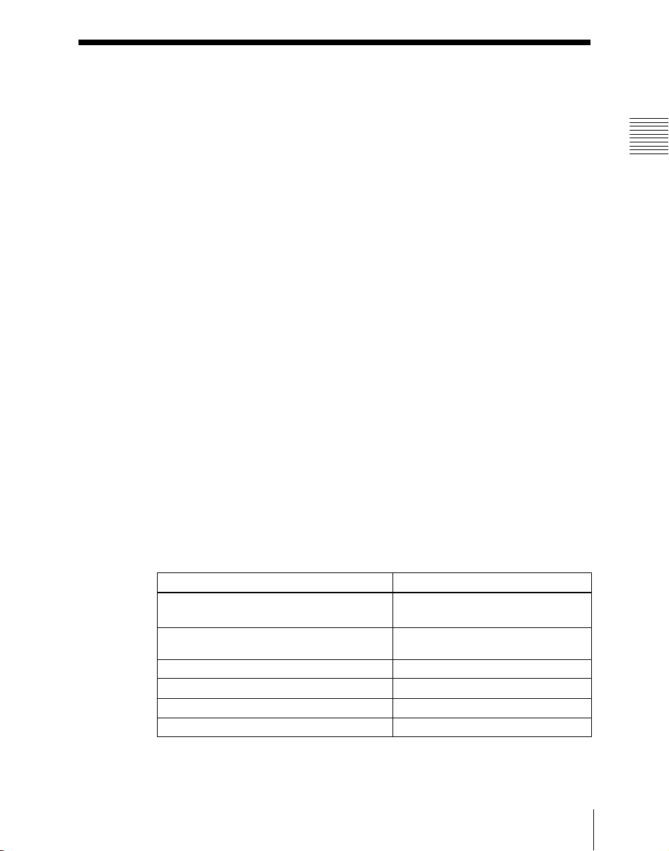
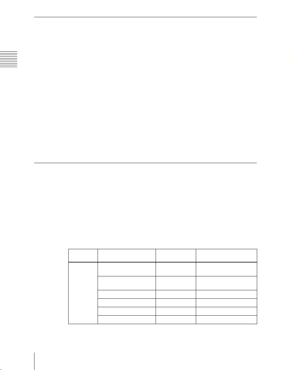
Principal components and naming
The formal product names of the principal components of the MVS-8000
system, and the terms used in this manual are as follows.
Formal product name Term used in this manual
MVS-8000/8000SF/8000A/8000ASF/8000G/
8000GSF Multi Format Switcher Processor
MVE-8000 (MKS-8800)/8000A Multi Format
DME Processor
MVE-9000 Multi Format DME Processor DME or DME processor or MVE-9000
CCP-8000-series Center Control Panel Control panel or center control panel
DCU-8000 (MKS-8700) Device Control Unit DCU or MKS-8700
DCU-2000 (MKS-2700) Device Control Unit DCU or MKS-2700
Switcher or switcher processor
a)
DME or DME processor or MVE-8000/
8000A
19Introduction
Page 21

Chapter 1 MVS-8000 Functions
a) Where there are differences among the MVS-8000/8000SF system, MVS-8000A/8000ASF
system, and MVS-8000G/8000GSF system, these may be noted specifically in the relevant
place.
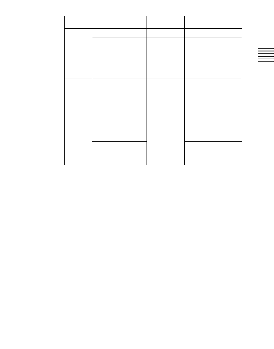
System nomenclature
The following terms are used for systems, depending on the combination of
installed options, and the signal format.
System configuration and features Term for system
System with installed option boards and
settings to support HDTV format
System with installed option boards and
settings to support SDTV format
A system in which the center control panel has
four M/E banks
A system in which the center control panel has
three M/E banks
A system in which the center control panel has
two M/E banks
Related manuals
The following manuals are supplied with the individual products of the MVS8000 Multi Format Switcher system.
MVS-8400/8300/8200 Switcher Processor Pack
• MVS-8400/8300/8200 Operation Manual
• MVS-8400/8300/8200 Installation Manual
HD system
SD system
4M/E system
3M/E system
2M/E system
20
MVS-8000A-C/8000AS-C Switcher Processor Pack
• MVS-8000A-C/8000AS-C Operation Manual
• MVS-8000A-C/8000AS-C Installation Manual
MVS-8000G-C/8000GS-C Switcher Processor Pack
• MVS-8000G-C/8000GS-C Operation Manual
• MVS-8000G-C/8000GS-C Installation Manual
MVS-8000SF-C Switcher Processor Pack
• MVS-8000SF-C Operation Manual
• MVS-8000SF-C Installation Manual
MVE-8000-C DME Processor Pack
• MVE-8000-C Operation Manual
• MVE-8000-C Installation Manual
MVE-8000A DME Processor Pack
Introduction
Page 22

• MVE-8000A Operation Manual
• MVE-8000A Installation Manual
MVE-9000-C DME Processor Pack
• MVE-9000-C Operation Manual
• MVE-9000-C Installation Manual
CCP-8000 Center Control Panel Pack
• CCP-8000 Operation Manual
• CCP-8000 Installation Manual
DCU-8000 Device Control Unit Pack
• DCU-8000 Operation Manual
• DCU-8000 Installation Manual
DCU-2000 Device Control Unit Pack
• DCU-2000-C Operation Manual
• DCU-2000-C Installation Manual
Chapter 1 MVS-8000 Functions
21Introduction
Page 23

Features of the MVS-8000 Multi Format Switcher System
Chapter 1 MVS-8000 Functions
The MVS-8000 Multi Format Switcher system boasts extensible high
performance and multifunctionality. The following are some of the principal
features of this system.
System configuration flexibility
Multiformat support
This system supports both HDTV and SDTV signal formats. The format
selection can be switched by a simple control panel operation. The MVS8000G supports either the HDTV or SDTV signal format, depending on the
software option selection.
Extensible system configuration
By suitable combination of options, the switcher can be configured with
various inputs and outputs, and different numbers of M/E banks. The system
offers the flexibility to change and expand as required.
You can connect up to two MVE-8000/8000A or MVE-9000 extensible DME
processors, each of which provides any number from one to four channels, for
a maximum of eight channels of DME functionality.
Powerful external device interfaces
By connecting to a Sony routing switcher or similar, a large system can be
built. From the control panel, it is also possible to operate other equipment,
including VTRs and disk recorders.
Powerful tally system
The complete system including routing switcher provides an all-inclusive tally
system. The system can be adapted to different applications and settings, using
multiple tally outputs, including both on-air and recording tallies.
Comprehensive video manipulation
M/E banks
Each mix/effects bank (M/E bank) is equipped with four keyers, and each
keyer is capable not only of chroma keying, but also independent key
transitions separate from the background transitions. The four keys can be
freely combined, to carry out four different program outputs.
Features of the MVS-8000 Multi Format Switcher System
22
Page 24

Powerful frame memory functions
In an MVS-8000 system, an HDTV system can hold 58 still image frames (88
frames in 720P/59.94 format), and an SDTV system can store 222 frames in
memory, while up to eight frames can be recalled and used simultaneously.
In an MVS-8000A system and MVS-8000G system, an HDTV system can
hold approximately 1,000 still image frames or 2,000 frames in 720P/59.94
format, and an SDTV system can hold approximately 5,000 frames in 480i/
59.94 format or 4,000 frames in 576i/50 format in memory, and up to eight
frames can be recalled and used simultaneously.
Link operation with DME
By means of the dedicated DME interface, a range of DME functions including
DME wipes and processed keys can be handled as switcher functions.
By connecting two MVE-8000/8000A or MVE-9000 units, in any
combination, you can interface to a maximum of eight DME channels.
Note that the MVE-8000A and MVE-9000 can also be used with this system
by connecting through an SDI interface.
Designed for use in a live broadcasting environment
Flexible control panel layout
Because of its modular design, the various sections of the control panel can be
laid out as required. This allows a flexible layout appropriate to the system
operation.
Chapter 1 MVS-8000 Functions
High-performance user interface
The menu control block provides a large color LCD panel, with rapid touchpanel menu selection.
The source name displays and buttons in the Flexi Pad
TM
and shotbox control
blocks have color backlit LCD displays. The signal names, and graphical
representations of the patterns associated with buttons provide intuitive
feedback, and allow the immediate decisions that are required in a live
operating environment.
23Features of the MVS-8000 Multi Format Switcher System
Page 25
Chapter 1 MVS-8000 Functions
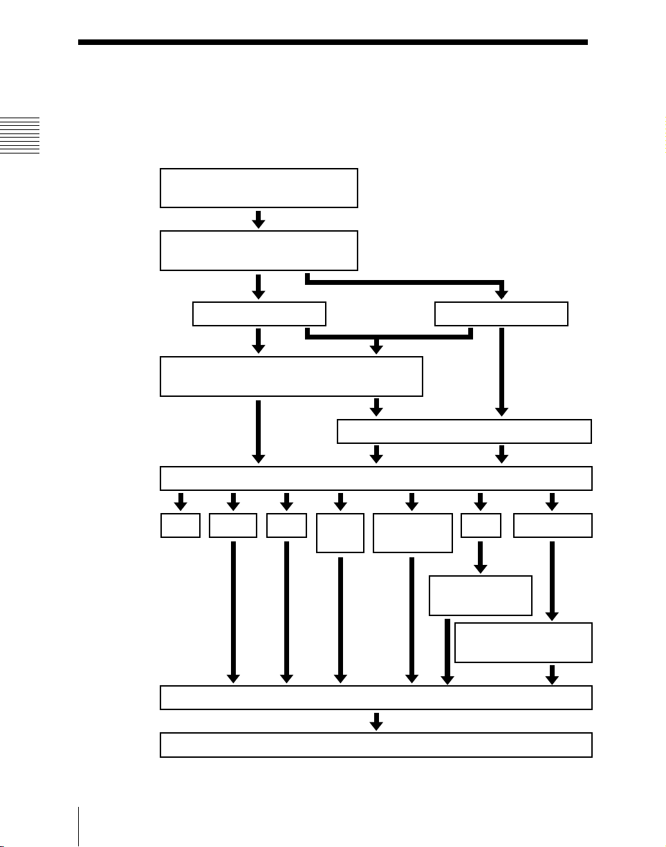
Video Processing Flow
The following illustration shows the flow of operations for carrying out a
transition on an M/E bank or the PGM/PST bank.
Select current background video
(page 25)
Select next transition (page 34)
Background
Select new background video (page 25)
Select transition type (page 41)
Cut Mix
NAM
Preview the effect of transition (page 46)
Super
mix
Keys 1 to 4
Make key settings (page 48)
Preset color
mix
Wipe
Make wipe
settings (page 60)
Make DME wipe settings
(page 72)
DME wipe
Video Processing Flow
24
Execute the transition (page 44)
Page 26
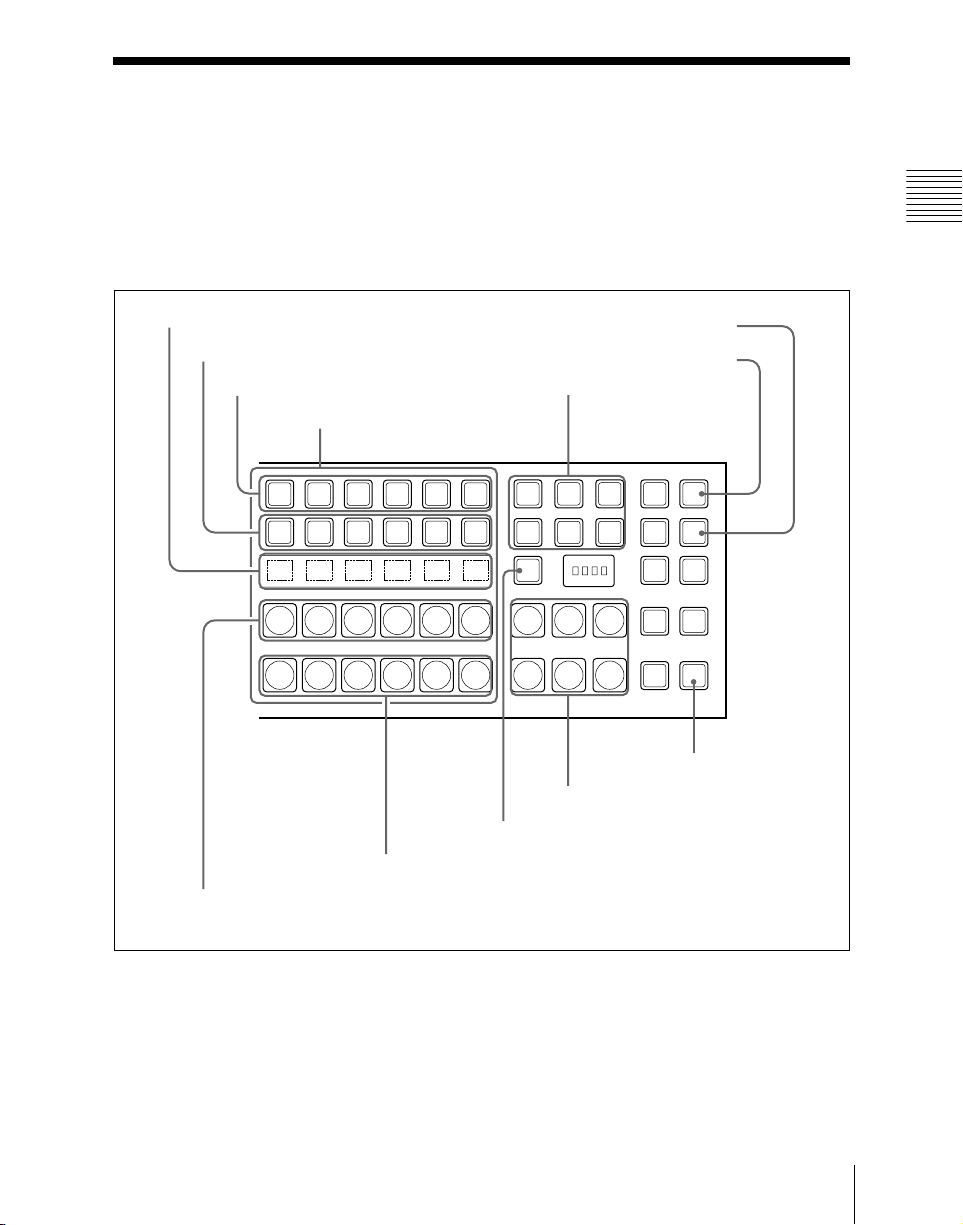
Signal Selection
You carry out signal selection with the cross-point buttons in the cross-point
control block of each M/E bank or the PGM/PST bank, and the buttons in the
auxiliary bus control block.
The number of buttons in each cross-point row may be 16, 24, or 32, but here
the description is of the 32-button case as an example.
Chapter 1 MVS-8000 Functions
Source name displays
Key 2 row
Key 1 row
Background A row
Cross-point buttons
Background B row
Reentry buttons
M/E
SHIFT
1
M/E
SHIFT
1
SHIFT
M/E
SHIFT
1
M/E
SHIFT
1
Reentry buttons
SHIFT button
KEY4 button
KEY3 button
M/E
2
M/E
2
M/E
2
M/E
2
XPT
M/E
3
M/E
3
M/E
3
M/E
3
HOLD
HOLD
MCRO
ENBL
HOLD
HOLD
KEY3
XPT
KEY4
MCRO
ASGN
XPT
AUTO
RUN
XPT
UTIL
UTIL button
Cross-point control block
25Signal Selection
Page 27
Chapter 1 MVS-8000 Functions
Basics of Signal Selection
Each of the M/E banks, PGM/PST bank and auxiliary bus control block has 32
cross-point buttons and three reentry buttons (four in the case of the auxiliary
bus control block).
These buttons are identified by numbers common to all of the banks and block,
and a signal is assigned to each number.
The basis of signal selection is to select, in a cross-point button row, the crosspoint button to which is assigned the desired signal.
Reentry buttons
To use the output of one M/E bank as background input to another bank, use
the reentry buttons [M/E1], [M/E2], and [M/E3] (on the auxiliary bus control
block, [M/E1], [M/E2], [M/E3], and [PGM]) in the cross-point control block
of the destination bank.
For example, to feed the output from the M/E-1 bank as the background B input
to M/E-2, in the M/E-2 cross-point control block, press the [M/E1] button in
the background B row.
Bus Selection
Each row of 32 cross-point buttons is shared by multiple buses.
For example, in the M/E-1 bank, the key 1 row of buttons can be assigned either
to the key 1 bus or to the key 3 bus. The [KEY3] button switches between these
two assignments.
To assign a bus to the cross-point buttons in the auxiliary bus control block,
press one of the AUX delegation buttons to select the bus.
26
Signal Selection
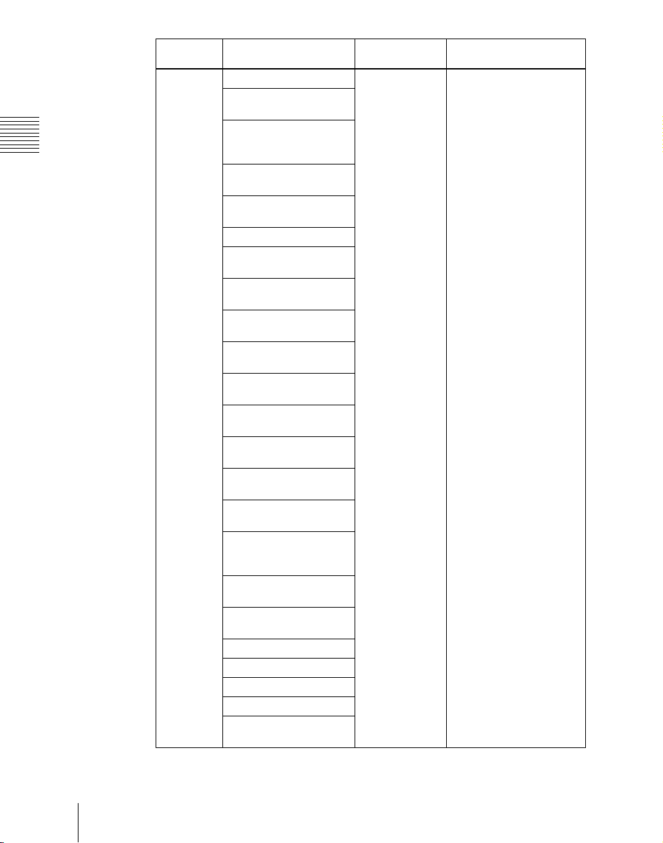
The following table illustrates the correspondence between buses and crosspoint button rows, and the delegation operations.
Bank Bus name Cross-point
M/E-1,
M/E-2,
M/E-3
Background A bus
Background B bus
Key 1 bus Key 1 row Turn off the [KEY3] button
Key 2 bus Key 2 row Turn off the [KEY4] button
Key 3 bus Key 1 row Turn on the [KEY3] button
Key 4 bus Key 2 row Turn on the [KEY4] button
a)
a)
button row
Background A
row
Background B
row
Delegation operation
–
–
Page 28
Bank Bus name Cross-point
PGM/PST
M/E-1,
M/E-2,
M/E-3,
PGM/PST
Program bus
Preset bus
DSK 1 bus DSK1 row Turn off the [DSK3] button
DSK 2 bus DSK2 row Turn off the [DSK4] button
DSK 3 bus DSK1 row Turn on the [DSK3] button
DSK 4 bus DSK2 row Turn on the [DSK4] button
Utility 1 bus Background A
Utility 2 bus Background B
DME external video bus Key 1 row Hold down the [UTIL]
DME utility 1 bus Key 2 row Hold down the [UTIL]
DME utility 2 bus Hold down the [UTIL]
a)
a)
button row
Program row –
Preset row –
row
row
Delegation operation
Chapter 1 MVS-8000 Functions
When [UTIL] button mode
is Hold, hold down the
[UTIL] button
button
button, and press the
[KEY4] button, turning it
off
button, and press the
[KEY4] button, turning it
on
27Signal Selection
Page 29
Chapter 1 MVS-8000 Functions
Bank Bus name Cross-point
Auxiliary
bus control
block
AUX1 to AUX48 buses 1st row, 2nd row Turn on the appropriate
MONITOR 1 to
MONITOR 8 buses
Frame memory source 1
and frame memory
source 2 buses
DME 1 to DME 8 video
buses
DME 1 to DME 8 key
buses
Edit preview bus
M/E-1 UTILITY 1 and
M/E-1 UTILITY 2 buses
M/E-2 UTILITY 1 and
M/E-2 UTILITY 2 buses
M/E-3 UTILITY 1 and
M/E-3 UTILITY 2 buses
P/P UTILITY 1 and P/P
UTILITY 2 buses
M/E-1 Key 1 fill to M/E-1
Key 4 fill buses
M/E-1 Key 1 source to M/
E-1 Key 4 source buses
M/E-2 Key 1 fill to M/E-2
Key 4 fill buses
M/E-2 Key 1 source to M/
E-2 Key 4 source buses
M/E-3 Key 1 fill to M/E-3
Key 4 fill buses
M/E-3 Key 1 source to
M/E-3 Key 4 source
buses
DSK 1 fill to DSK 4 fill
buses
DSK 1 source to DSK 4
source buses
M/E-1 external DME bus
M/E-2 external DME bus
M/E-3 external DME bus
P/P external DME bus
DME UTILITY 1 and
DME UTILITY 2 buses
button row
Delegation operation
buttons in accordance with
the signal assignment
made in the Setup menu.
28
Signal Selection
Page 30

a) Dual background bus mode (see below) can be selected.
Dual background bus mode
In this mode, the shifted signal on the background A row can be selected on the
key 1 row, and the shifted signal on the background B row can be selected on
the key 2 row.
To switch this mode on and off, it is necessary to assign this function to the
[PRE MCRO] button in the cross-point control block.
For details of the assignment operation, see “Overall Control Panel Settings
(Config Menu)” in Chapter 16 (Volume 2).
Note
For the following switcher banks, dual background bus mode is not available.
• When set to “Dual M/E Assign”
• When M/E Config is set to “DSK”
Signal Assignment and Selection
Assigning signals to buttons
Each of the 32 cross-point buttons and reentry buttons has a corresponding
button number, to which you assign a signal.
In addition to the signals input to the PRIMARY INPUTS 1 to 80 connectors
(1 to 34 connectors for the MVS-8000SF/8000ASF/8000GSF) on the rear
panel of the switcher, you can also select signals generated within the switcher.
Each button has assigned to it a video signal and a key signal, forming a pair.
You can set these video and key combinations in a Setup menu.
Chapter 1 MVS-8000 Functions
For details of Setup menu operations, see “Cross-Point Settings (Xpt Assign
Menu)” in Chapter 16 (Volume 2).
29Signal Selection
Page 31

Chapter 1 MVS-8000 Functions
Cross-point button control block button numbers
Shift button
M/E
1
M/E
1
SHIFT
M/E
1
M/E
1
XPT
M/E
M/E
DSK3
HOLD
2
3
XPT
M/E
M/E
KSK4
HOLD
2
3
MCRO
MCRO
ENBL
ASGN
M/E
M/E
XPT
AUTO
2
3
HOLD
RUN
M/E
M/E
XPT
UTIL
2
3
HOLD
1, 2, 3, 4, ....... ....... 29, 30, 31 121 123
32, 33, 34, 35, ....... ....... 60, 61, 62 125 127
(first button numbers)
(second button numbers)
Shift button
On each M/E bank and the PGM/PST bank, each cross-point button and reentry
button has two button numbers, and you use the shift button to switch between
these numbers.
In the case of a 32-button layout, the button numbers are as follows.
Cross-point control block button numbers
Button Number when the shift
button is not pressed
From the left end to the 31st
1 to 31 32 to 62
Number when the shift
button is pressed
button
Reentry buttons 121 to 123 125 to 127
Note
On the MVS-8000A/8000G, you can use the rightmost button (number 32) as
a [SIDE FLAG] button. In this case, the shift button moves one to the left, to
number 31, and the button numbers are offset by one.
For details of the [SIDE FLAG] button, see “Cross-Point Settings (Xpt Assign
Menu)” in Chapter 16 (Volume 2).
Switching button numbers
The rightmost (32nd) button functions as a shift button.
(The shift button function can be disabled in a Setup menu.)
When selecting the signals of button numbers 1 to 31, press the cross-point
button for the desired signal.
To select button numbers 32 to 62, hold down the shift button, and press the
cross-point button for the desired signal.
30
Signal Selection
Page 32

Button numbers in the auxiliary bus control block
2ND button
1, 2, 3, 4, ....... ....... 29, 30, 31 121 124
(1st row)
LEVEL
LEVEL
LEVEL
LEVEL
1
2
3
MCRO
MCRO
AUX1AUX2AUX3AUX4AUX5AUX6AUX7AUX8AUX9AUX10AUX11AUX12AUX13AUX14AUX15AUX16AUX17AUX18AUX19AUX20AUX21AUX22AUX23AUX24AUX25AUX26AUX27DME
32, 33, 34, 35, ....... ....... 60, 61, 62 125 128
(2nd row)
UTIL1
DME
UTIL2FM1FM2
EDIT
PVW
MCRO
DEST
1
2
SHIFT
M/E
M/E
M/E
P/P
1
2
3
M/E
M/E
M/E
P/P
1
2
3
When the [2ND] button is unlit
The cross-point buttons and reentry buttons in the auxiliary bus control block
have separate upper (1st row) and lower (2nd row) numbers.
In the case of a 32-button layout, the button numbers are as follows.
Auxiliary bus control block button numbers ([2ND] button unlit)
Button Button Button numbers
1st row From the left end to the 31st button 1 to 31
Reentry buttons 121 to 124
2nd row From the left end to the 31st button 32 to 62
Reentry buttons 125 to 128
When the [2ND] button is lit
Different buses can be assigned to the 1st-row buttons and 2nd-row buttons.
When the 32nd button is set as a shift button, the 1st-row buttons and 2nd-row
buttons both have the following button numbers.
Auxiliary bus control block button numbers ([2ND] button lit)
RTR
4
2ND
3
KEY
XPT
HOLD
XPT
HOLD
Chapter 1 MVS-8000 Functions
Button Number when the shift
button is not pressed
From the left end to the 31st
1 to 31 32 to 62
button
Reentry buttons 121 to 124 125 to 128
Inhibiting cross-point button operations
For each cross-point button, you can temporarily inhibit operations.
Number when the shift
button is pressed
31Signal Selection
Page 33

Chapter 1 MVS-8000 Functions
Note
This setting is cleared when you reset the control panel.
Assigning a button to the function of disabling cross-point button
operation
You can assign the button to be used for the operation to the [PRE MCRO]
button, in setup. (See Chapter 16, “Overall Control Panel Settings (Config
Menu)” (Volume 2))
You can also use the [Inhibit Set] and [Inhibit All Clear] functions, assigned to
user preference buttons. (See Chapter 16, “Setting Button Assignments (Prefs/
Utility Menu)” (Volume 2))
Buses for which operations can be inhibited
This setting applies to the AUX control block and switcher bank cross-point
buttons.
For example, if you make the setting for one cross-point button in a switcher
bank, this inhibits operation of all cross-point buttons with the same number in
the following buses.
The corresponding name also disappears from the source name display.
• Background A, background B
•Keys 1 to 4
• Utility 1, utility 2
• DME utility 1, DME utility 2
• External DME
To inhibit operation of a cross-point button
Hold down the button which “Inhibit Set” is assigned, and press the cross-point
button whose operation you want to inhibit.
The button you pressed flashes amber, and this makes the operation inhibited.
32
Note
Even when you inhibit operation of a cross-point button, macro attachment
settings are still possible (see page 218).
To clear a cross-point button operation inhibit setting
Hold down the button to which “Inhibit Set” is assigned, and press the button
whose operation is inhibited (flashing amber).
This clears the operation inhibit setting for the button you pressed.
To clear all operation inhibit settings
Press the button to which “Inhibit Set” is assigned and the button to which
“Inhibit All Clear” is assigned simultaneously.
Signal Selection
Page 34

Selection of signals linked with the audio mixer
When you select a signal in a switcher bank background A row or AUX bus
control block which is set to be linked with the audio mixer, the program output
of the audio mixer follows the signal selection.
For details of the setting, see Chapter 16, “Cross-Point Settings (Xpt Assign
menu)” (Volume 2).
Note
• For details of audio mixers that can be connected, contact your Sony service
or sales representative.
• When the signal is switched with a snapshot, keyframe, and so on, the audio
mixer is not linked.
• When bus fixed mode is selected in setup (see page 45), the audio mixer
program output is linked to the bus output as the background.
Signal Name Display
You can attach a name (source name) to each signal assigned to a cross-point
button, with a maximum of 16 characters.
• The source name displays in the cross-point control block and auxiliary bus
control block show the source names of the video signals assigned to
numbers 1 to 31.
• To display the source names for numbers 32 to 62, press the [SHIFT] button
to the right of the source name displays.
• To display the source names of the key signals assigned to buttons, hold
down the [SPLIT] button in the key control block or the [KEY] button in the
auxiliary bus control block.
Chapter 1 MVS-8000 Functions
Colors of lit cross-point buttons
In a particular row of cross-point buttons, only the last pressed button is
effective, and lights amber or red. The amber indicates the “low tally” state,
and the red indicates the “high tally” state, to indicate whether or not the
selected signal appears in the final output video.
Significance of colors of lit cross-point buttons
Color State Significance
Amber Low tally Does not appear in final output video
Red High tally Appears in final output video
33Signal Selection
Page 35

Chapter 1 MVS-8000 Functions
Transitions
In the M/E banks and PGM/PST bank, the switch from the current video stream
(appearing on the corresponding program monitor) to a new video stream is
referred to as a transition.
Selecting the Next Transition
To execute a transition, it is first necessary to decide how the image will be
changed as a result of the transition. This selection is carried out using the next
transition selection buttons (see page 261) in the transition control block of
each M/E or PGM/PST bank.
For details of operations, “Basic Operating Procedure” (page 340).
In the M/E banks and PGM/PST bank, you can change one of the images, the
background, and keys 1 to 4 (downstream keys 1 to 4 in the PGM/PST bank),
and also vary combinations of these simultaneously.
The following are examples of transition.
Changing the background
A background transition switches from the video currently selected on the
background A bus (the current video) to the video selected on the background
B bus (the new video).
34
Transition
Background BBackground A
In the default selection of flip-flop mode (see page 45), the background always
switches in the direction from the A bus to the B bus. When the transition
completes, the cross-point selections on the A and B buses are interchanged.
Transitions
Page 36

Inserting and deleting a key
You can insert one or more of the four keys (downstream keys on the PGM/
PST bank).
If you select a key which is already inserted, the transition will delete the key.
A simultaneous combination of deleting and inserting keys is also possible.
Key 1
Insert
Delete
Inserting or deleting key 1 and key 2
Transition
Key 1
Key 2
Key 2
Chapter 1 MVS-8000 Functions
Deleting key 1 and inserting key 2
35Transitions
Page 37

Chapter 1 MVS-8000 Functions
Simultaneously changing the background and keys
You can change any of the four keys (downstream keys on the PGM/PST bank)
and the background at the same time.
Key 1
Transition
Key 2
Changing the background and key 2 simultaneously
Key 1
Selecting the key priority
If a number of keys are already inserted in the current video, you can check or
change the key priority, that is to say, the order in which the keys are overlaid.
When a key priority ([KEY PRIOR]) is selected as the next transition, you can
also change the key priority in the new video.
For details of this operation, see “Key Priority Setting” (page 343).
Transitions
36
Transition
Key 2
Changing the background and keys 1 to 4 simultaneously
Key 3
Key 4
Page 38

The key priority values go from 1 to 4, with a higher priority key being “in
front” as seen on the screen.
1
2
3
4
Priority sequence on the screen
Independent Key Transitions
What is an independent key transition?
In addition to common transitions, it is possible to carry out independent
transitions on the keyers of the M/E banks and PGM/PST bank. These are
called “independent key transitions.”
By carrying out an independent key transition in combination with a common
transition, different transition types can be used for the background and keys.
It is also possible to use different transition types for key insertion and key
deletion by means of a Setup menu setting.
For details of this operation, see “Basic Independent Key Transition
Operations” (page 364).
Chapter 1 MVS-8000 Functions
The following description compares the independent key transition with a
common transition, taking a simultaneous change of the background and key
as an example.
Video used in the transition
Background A
Background B
Key to insert
37Transitions
Page 39

Chapter 1 MVS-8000 Functions
Effect of a common transition
In the case shown in the previous illustration, carrying out a common transition
produces the following change in the image.
Transition type: wipe
Effect of a common transition
Same wipe is applied to
background and key.
Effect of use with an independent key transition
The key is inserted with an independent key transition as the background
changes with a common transition, providing the following result.
Transition type:
wipe
Effect of a background transition and independent key transition
Independent key
transition type:
wipe
Different wipe patterns are applied to
the background and key transitions.
Combining other transitions with independent key transitions
When you set a common transition and a key independent transition for the
same key, you can apply two different effects such as a wipe and mix (dissolve)
(see page 41) to the key simultaneously.
When carrying out such a combination of transitions simultaneously on a key
as auto transitions (see page 45), the result depends on the timing of pressing
the respective [AUTO TRANS] buttons.
38
Transitions
Page 40

Simultaneous execution
If the [AUTO TRANS] buttons for the two transitions are pressed
simultaneously, the following is the result.
Note that in both cases the common transition is a wipe and the independent
key transition is a mix (dissolve).
Deleting a key with simultaneous transitions: With the key inserted, it is
deleted simultaneously with the two transitions.
When the common transition completes, even if the independent key
transition is still not completed, the two end simultaneously.
Chapter 1 MVS-8000 Functions
Wipe and mix
(dissolve) are
carried out
simultaneously.
Deleting a key with simultaneous transitions
The key is deleted,
even if the
independent key
transition has not
completed.
Inserting a key with simultaneous transitions: With the key not inserted, it
is inserted simultaneously with the two transitions. If the common
transition or independent key transition ends first, the other continues to
completion.
Wipe and mix
(dissolve) are
carried out
simultaneously.
Inserting a key with simultaneous transitions
The transitions
continue until both
are completed.
Time offset execution
If the [AUTO TRANS] buttons for the two transitions are pressed with a time
offset, the following is the result.
Note that in both cases the common transition is a wipe and the independent
key transition is a mix (dissolve).
39Transitions
Page 41

Chapter 1 MVS-8000 Functions
Time offset execution with the key inserted: With the key inserted, it is
deleted with the two transitions acting with a time offset.
Whichever button is pressed first, when the common transition completes,
even if the independent key transition is still not completed, the two end
simultaneously.
Example: When the independent key transition [AUTO TRANS] button
is pressed later
The key is deleted,
Common transition
(wipe) start
Time offset execution with the key inserted
Independent key
transition (mix) start
even if the
independent key
transition has not
completed.
Time offset execution with the key not inserted: With the key not inserted,
it is inserted with the transition whose [AUTO TRANS] button is pressed
first.
Since the key is then in the inserted state, with the transition whose [AUTO
TRANS] button is pressed later, the key is deleted. When the key is
completely deleted, both transitions complete.
40
Transitions
Page 42

Example 1: When the independent key transition [AUTO TRANS]
button is pressed later
Common transition
(wipe) start
Example 2: When the common transition [AUTO TRANS] button is
pressed later
Independent key
transition (mix)
start
The transition
completes with the
key deleted.
Chapter 1 MVS-8000 Functions
Transition Types
Selecting the transition type determines the way in which the transition occurs.
Carry out the type selection with the transition type selection buttons in the
transition control block of each M/E or PGM/PST bank.
For details of this operation, see “Basic Operating Procedure” (page 340).
The following are the transition types.
Mix
This is a dissolve, in which the new video progressively fades in over the
current video, with the sum of the two video outputs maintained constant. At
the mid-point of the transition (when the fader lever is in the center position),
the output of each is 50%.
This transition type can also be selected for an independent key transition. In
this case, the key either dissolves in or dissolves out similarly, with the
progress of the transition.
Independent
key transition
(mix) start
Time offset execution with the key not inserted
Common
transition (wipe)
start
The transition
completes with the
key deleted.
41Transitions
Page 43

Chapter 1 MVS-8000 Functions
NAM (non-additive mix)
In this dissolve, the current video and new video signals are compared, and the
signal with the higher luminance level is given priority in the output. The
current video is maintained at 100% output for the first half of the transition as
the new video increases progressively to 100%, then the current video is
progressively reduced from 100% to zero in the second half with the new video
maintained at 100% output.
Note
This transition type is not available for an independent key transition.
Super mix
In this dissolve, the current video is maintained at 100% output for the first half
of the transition as the new video is mixed while increasing progressively to
100%, then the current video is progressively reduced from 100% to zero in the
second half with the new video maintained at 100% output.
Note that you can set the output levels of the current and new video signals at
the mid-point of the transition, in the range 0 to 100%. (See “Super Mix
Settings” (page 349).)
Note
This transition type is not available for an independent key transition.
Preset color mix
Transitions
42
This is a two-stage dissolve, comprising two transitions, the first a dissolve to
a color matte, and the second from the color matte to the new video.
In the first transition, the current video is replaced by the color matte in a mix
(dissolve), then in the second transition the color matte is replaced by the new
video also in a mix (dissolve). You can specify the color matte by luminance,
saturation, and hue values. (See “Color Matte Settings” (page 350).)
Also, in place of a color matte you can use an image selected on the utility 2
bus.
Notes
• This transition type is not available for an independent key transition.
• In the multi-program mode, you can use a preset color mix only when
selecting the background for the next transition.
One-stroke mode and one-time mode
• You can make a setting such that a preset color mix is carried out in a single
transition. This is called “one-stroke mode.”
Page 44

Note
When the bus fixed mode is selected with a Setup menu setting, a preset color
mix is always carried out in the one-stroke mode.
• You can also make a setting such that when a preset color mix is completed,
the next transition switches to the previous transition type automatically.
This is called “one-time mode.”
When only the background is changed
Current video Color matte New video
Preset color mix (changing background only)
When a key is inserted
Chapter 1 MVS-8000 Functions
Key fades out
Key
Preset color mix (transition including key)
When a key is
selected as the next
transition
When no key is selected
Key fades in
By means of a Setup menu setting, it is possible to preserve the key state while
carrying out the color matte mix.
43Transitions
Page 45

When, with a key inserted, a key is selected in the next transition
Chapter 1 MVS-8000 Functions
Key
Wipe
A wipe replaces the current video by the new video according to a
predetermined pattern. This transition type can also be selected for an
independent key transition.
For details, see “Wipes” (page 60) and Chapter 5 “Wipes” (page 437).
DME wipe
Using a DME effect, it is possible to obtain a transition to a new image from
the current image, as in a wipe. You can also use this transition type as an
independent key transition.
For details, see “DME Wipes” (page 72) and Chapter 6 “DME Wipes” (page
465).
Clip transitions
Linked to a mix (dissolve) or wipe transition, a frame memory clip (movie) is
played back.
Key state preserved
Key gradually
removed
Preset color mix (when set to preserve key state)
Note
The clip transition function is only supported on the MVS-8000A/8000G.
Cut
A cut switches instantaneously from the current video to the new video. When
the next transition is a key transition, the key cuts in or out instantaneously.
Executing a Transition
There are two modes of executing a transition: an auto transition by button
operation or a manual transition using the fader lever.
Transitions
44
Page 46

It is also possible to combine both methods, taking control with the fader lever
of an auto transition which has partly completed, or complete a transition
started with the fader lever as an auto transition.
By combining common transitions with independent key transitions, different
transition types can be applied to the background and keys, for example
allowing a key wipe combined with a background dissolve. (See “Executing a
Transition” (page 351).)
When the audio mixer is linked in setup, you can carry out an auto transition,
and also switch the sound with the audio mixer. (See “Transition linked to the
audio mixer” (page 342).)
Auto transitions
Cut
A cut switches instantaneously from the current video to the new video. When
the next transition is a key transition, the key cuts in or out instantaneously.
Auto transition
The transition from the current video to the new video is carried out
automatically at a constant rate, using the transition effect selected as the
transition type.
You can set the transition rate in advance. (See “Setting the Transition Rate”
(page 352).)
Manual transitions
Using the fader lever, you can manually control the progress of the transition.
Moving the fader lever from one end of its travel to the other completes the
transition.
Chapter 1 MVS-8000 Functions
Flip-flop mode and bus fixed mode
The following describes the difference between flip-flop mode and bus fixed
mode, taking an M/E bank as an example; the functionality is the same,
however, on the PGM/PST bank.
Normally, when a background transition is carried out on an M/E bank, the
signals selected on the A and B rows of cross-point buttons are interchanged at
the end of the transition. That is to say, except during a transition, the
background output is always from the background A bus. This is called “flipflop mode.”
The alternative is known as “bus fixed mode,” in which there is no bus
interchange. In this mode, when the fader lever is at the top of its travel the
output from the A bus is always 100%, and when the fader lever is at the bottom
of its travel the output from the B bus is 100%.
45Transitions
Page 47

Chapter 1 MVS-8000 Functions
BLACK
A
BLACK
B
Flip-flop mode
BLACK
A
BLACK
B
Buttons lit
For details of fader lever operation in bus fixed mode, see page 361.
Transition preview
With the preview output of the M/E banks and PGM/PST bank, you can check
the effect of a transition in advance. To carry out a transition preview, press the
[TRANS PVW] button in the transition control block. (See “Transition
Preview” (page 363).)
Note
In multi-program mode, DSK mode (page 199) or bus fixed mode (page 45),
it is not possible to carry out a transition preview.
Pattern limit
When a wipe or DME wipe pattern is selected for the transition, you can
specify the range of movement of the wipe pattern through the course of the
transition, for each bank independently.
When the pattern limit function is enabled, carrying out a transition results in
the following effect for example settings.
• When the limit value is set to 50%, the effect at the end of the transition is
the same as when the fader lever is at the center position in the normal case
(with the pattern limit function disabled); the wipe pattern does not complete.
• When the limit value is set to 0%, the wipe effect is completely disabled, and
carrying out the transition produces no change in the image.
Bus fixed mode
Fader
lever
BLACK
A
BLACK
B
Flip-flop mode and bus fixed mode
46
Transitions
Page 48

• When the limit value is set to the maximum 100%, the image changes in
exactly the same way as when the pattern limit function is off, but when the
transition is completed, the cross-point selections on the background A and
B buses do not interchange.
You can specify the limit value either by entering a numeric value in the menu,
or by operating the fader lever to set the fader lever position. (See “Pattern
Limit” (page 355).)
Note
The pattern limit function is not available in an independent key transition.
Fade to black
The PGM/PST bank provides a fade-to-black function, controlled with the
[FTB] button in the fade to black control block. (See “Fade to Black” (page
369).)
Note
In multi-program mode or DSK mode, it is possible to carry out a fade-to-black
on a number of programs simultaneously.
You can also make a Setup menu setting such that a fade-to-black does not
apply to particular programs.
For details of the setting, see “Settings Relating to Video Switching (Transition
Menu)” in Chapter 16 (Volume 2).
Chapter 1 MVS-8000 Functions
47Transitions
Page 49

Chapter 1 MVS-8000 Functions
Keys
A key is an effect in which a part of the background image is replaced by an
image or superimposed text. The signal determining how the background is cut
out is termed “key source,” and the signal that replaces the cut-out part is
termed “key fill.” The system component responsible for processing a key is
referred to as a keyer.
Each M/E bank and the PGM/PST bank has four keyers, and all of these keyers
provide the same functions.
Key Types
The key type indicates the manner in which the key source signal is used to cut
out the background. In each bank, you can use the following key types. You
can select the key type using the key type selection buttons in the key control
block, or by a setting in the Type menu for the keyer. (See “Key Type Setting”
(page 379).)
• Luminance key
• Linear key
• Color vector key
• Chroma key
• Wipe pattern key
• Key wipe pattern key
Luminance key
Linear key
Color vector key
Keys
48
The background is cut out according to the luminance (Y) of the key source
signal, and at the same time the key fill signal is cut out and then added to the
background signal.
This is a type of luminance key, but there is a reduced variability in gain,
allowing more precise adjustment.
The key signal is created from a combination of the luminance and
chrominance components of the key source signal. When perfect keying is not
possible with a luminance key, this allows a key signal to be created even if the
luminance level is low, provided that the colors have high saturation.
Page 50

Clean mode
In a luminance key, linear key or color vector key, you can enable the clean
mode. When the clean mode is on, the key source does not affect the key fill,
which is added unchanged to the background. This improves the keyed image
quality, but means that the part of the key fill signal which is not to be inserted
must be completely black, or it will color the background. You set the clean
mode with the Type menu of the respective keyer. (See “Setting the key type in
a menu” (page 379).)
Note that in the following situations, the clean mode goes off, and cannot be
turned on.
• When the key type is a pattern key
• When key inversion is on
• When the key fill is a matte
• When the key edge is an outline
• When the key edge is normal with soft edge being on
• When fine key is on
• When the key positioner is on
Chroma key
A key signal based on a particular color is used to cut out the background, and
the key fill is then inserted. The inserted signal is also referred to as the
foreground, and the composite image is called a chroma key image.
Chapter 1 MVS-8000 Functions
Foreground
Chroma key image
Background
Normal mix and additive mix
In creating a chroma key image, either a normal mix or an additive mix can be
used. To select which, use the Type >Chroma Adjust menu for the keyer. (See
“Chroma Key Composition” (page 381).)
49Keys
Page 51

Normal mix: The foreground is cut out with the key signal, and then combined
with the background, which has also been cut out with the key signal.
Additive mix: The background, which has been cut out with the key signal, is
combined with the unshaped foreground. This is effective for a naturallooking composite when the scene includes glass or other translucent
objects.
Chapter 1 MVS-8000 Functions
Plane function
In an additive mix, the foreground is not shaped by the key signal, and
variations in the (blue) background appear in the composite image. To prevent
this, it is possible to set a particular luminance level for the background, and
any parts below this level are cut forcibly.
Methods of adjusting the composite obtained from chroma keying include
automatic adjustment with the auto chroma key function, and manual
adjustment carrying out the necessary processing separately. The optimum
results will be obtained by first carrying out adjustments with the auto chroma
key function, then making any fine adjustments as required.
The following manual adjustments are possible.
Key active
When this function is off, only the foreground is output and you can make
adjustments of color cancel (see the next paragraph).
Color cancel
If the foreground image includes shades of the background color, turn this
function on to remove the color from the foreground image.
Chroma key window
You can adjust the range over which the key signal is determined as matching
the specified hue. When this adjustment is off the default ranges are used.
50
Chroma keying generates a key signal based on a particular color (reference
color) in the foreground (typically a plain blue background), and the “window”
refers to the range of colors which are regarded as matching this specified
reference color to create the key signal.
As seen on a vectorscope (that is, in the hue-saturation color space), the range
for this matching corresponds to a truncated sector. This range is specified by
two parameters: the “Angle” parameter, which determines the range of the hue
parameter, and the “Crop” parameter, which determines the degree of
truncation (see the following figure).
Keys
Page 52

Angle
a)
Reference color
specified by Hue
setting
a)
Crop
Range of colors remaining
as foreground
a) The Crop and Angle values do not change even if
you use the auto chroma key function.
Range of colors creating the key signal
(to be replaced by background signal)
Window adjustment
Y balance
In normal chroma keying, the key signal is based on the chrominance
component only, and all elements of the foreground with the same hue are
replaced by the background. Using the Y balance function, you can specify a
luminance level range within which the key is active, and replace the specified
part by the background.
You can use the Y balance function independently on the key signal for the
composition and the key signal for the color cancel function. When applied to
the key signal for the composition, this produces the foreground with the color
cancel effect applied. This can therefore be used to provide an impression of
smoke, for example.
When the Y balance function is applied to the color cancel key, the relevant
part is output in its original color without canceling, and therefore it is possible
to combine colors which are the same color as the background (i.e. typically
blue) in the foreground.
Chapter 1 MVS-8000 Functions
Chroma key shadow
This function provides a more realistic treatment when the shadow of an object
in the field of view falls on the blue background. Since parts of the blue
background darker than a specified intensity are treated as shadows, there is no
effect on cutting out of the foreground.
Video signal adjustment
You can vary the foreground signal gain, or change the hue. There are separate
adjustments for the gain of the overall video signal, and Y and C components.
51Keys
Page 53

For details of video adjustment operations and the adjustment items, see
“Chroma Key Adjustments” (page 382).
Wipe pattern key
This uses the wipe pattern selected for a transition as the key source.
Chapter 1 MVS-8000 Functions
Key wipe pattern key
This uses the wipe pattern selected for an independent key transition as the key
source.
Note on wipe pattern modifiers
In a wipe pattern key or key wipe pattern key, you can apply various
modifications, depending on the pattern used, and the modifiers in common
with a wipe.
However, modifiers which relate to the wipe direction and edge are not
reflected.
Key Modifiers
Edge modifiers
You can apply borders and other effects to the edge of the key. (See “Key Edge
Modifications” (pages 390 and 410).)
Normal
This is the state with no key edge modifiers applied.
52
Keys
Page 54

Border
This applies a uniform width border to the edge of the key. You can adjust the
border width and density. You can also enable the separate edge function, and
adjust the top, bottom, left, and right border widths separately.
Drop border
This applies a border below and to the right for example, of the key. You can
adjust the border width, position, and density.
Chapter 1 MVS-8000 Functions
Shadow
This applies a shadow below and to the right for example, of the key. You can
adjust the shadow width, position, and density.
53Keys
Page 55

Chapter 1 MVS-8000 Functions
Outline
This uses the outline of the original key as the key. You can adjust the width
and density of the outline. You can also enable the separate edge function, and
adjust the top, bottom, left, and right outline widths separately.
Emboss
This applies an embossing effect to the outline of the key. You can adjust the
width and position of the embossing, and the density. You can adjust the
density separately for key fill and key edge. When embossing is on, the Fine
Key and zabton functions go off.
Soft edge
This softens the edge of the key.
Zabton
This inserts a translucent pattern behind a key. You can adjust the pattern size,
softness, density and color.
Edge type and key fill/key source position
The key edge modification function has two modes: a mode (“key drop ON
mode”) in which the key fill/key source position moves downward, and a mode
(“key drop OFF mode”) in which it does not move downward.
Key drop ON mode: The key fill/key source position moves downward by
eight scan lines or four scan lines. When a drop border or shadow is
selected, it is possible to apply a border to the top edge of the key.
Key drop OFF mode: The key fill/key source position does not move. When
a drop border or shadow is selected, it is not possible to apply a border to
the top edge of the key.
In the key drop ON mode, a menu setting selects between the mode (“4H
mode”) in which the key fill/key source position is lowered by four scan lines,
and the mode (“8H mode”) in which the key fill/key source position is lowered
by eight scan lines.
When Fine Key is on, the edge width is forced to the range 0.00 to 4.00.
Note that in the following situations, the key drop mode is forcibly turned on.
Keys
54
Page 56

Edge fill
• When the edge type is border, outline, or emboss
• When the edge type is normal with soft edge being on
• When Fine Key is on
To fix key fill / key source in key drop off mode
In the Edge menu, switch frame delay mode on (see page 393).
Regardless of the fine key and edge type settings, key fill and key source are
fixed in key drop off mode. In this mode key image has a one-frame delay.
Notes
• This function is only valid on the MVS-8000G/8000GSF.
• This function uses the resizer, and therefore the normal effect of the setting
is not obtained while using DME wipe or other effect that uses the resizer.
When a border, drop border, or shadow modifier is selected, you can select a
signal to fill these edge effects.
The edge fill may be either the signal from the dedicated color matte generator,
or the signal currently selected on the utility 1 bus.
In the case of an outline, there is no edge fill signal selection, because the key
fill signal fills the outline, and the rest of the image remains as the background.
For the emboss effect, in place of the edge fill signal, the emboss fill matte 1
and emboss fill matte 2 signals are used.
Chapter 1 MVS-8000 Functions
Masks
A mask is used to inhibit the effect of a key over a part of the image. This
allows parts of the background which would otherwise be keyed to be
protected, or to correct the key if it is not of the desired shape.
For details of masking operations, see “Masks” (pages 397 and 414).
Key mask and background mask
There are two types of mask: a key mask and a background mask.
Key mask: This masks out a part of the key, which will result in the
background appearing.
55Keys
Page 57

Chapter 1 MVS-8000 Functions
Background mask: This masks out a part of the background, which will result
in the key fill appearing.
Masked area (box)
Main mask and subsidiary (“sub”) mask
Each keyer allows two masks to be used simultaneously, and these are referred
to as the main mask and the sub mask. The signal that determines the mask
shape and size is termed the mask source, and different sources are used for the
main mask and sub mask.
Main mask: This uses the signal from the dedicated box generator provided
on each keyer, or the signal from the dedicated pattern generator as the
mask source.
When the box generator is selected, a rectangular mask is formed. You can
adjust the positions of the four sides of the box separately.
When the pattern generator is selected, you can select the pattern and apply
modifiers.
Sub mask: This uses the wipe generator signal or the signal selected on the
utility 1 bus, as the mask source.
When the wipe generator is selected, the patterns and the pattern modifiers
are the same as in a wipe transition.
Key Memory
The key memory function allows the keyer settings on each cross-point button
to be automatically stored, so that the next time the same cross-point button is
selected these settings are recalled automatically.
There are two modes for key memory: simple mode and full mode.
The parameters stored in each mode are as follows.
Simple mode: key type, clean mode (including the plane setting for chroma
keying), key position, key inversion, and adjustment values for the
particular key type (Clip, Gain, Density, Filter, etc. This includes color
vector key, wipe pattern key, key wipe pattern key, and chroma key.
However, in the case of a chroma key, it excludes color cancel, Y balance,
foreground CCR, window, and shadow.)
Key mask
Background mask
56
Keys
Page 58

Full mode: All settings except transition (the same parameters as simple mode,
Fine Key, key modifiers, main and sub mask settings, chroma key detailed
settings, and so on)
For the settings for these modes, see “Settings Relating to Keys, Wipes and
Frame Memory (Key/Wipe/FM Menu)” in Chapter 16 (Volume 2).
Key Snapshots
Key settings other than the key on/off status and the key priority can all be
instantaneously saved in a dedicated register, for recall when required. A key
snapshot comprises three values: a cross-point button number, key memory full
mode, and independent key transition, and can be called in any combination.
There are four key snapshot registers for each keyer.
For details of key snapshot operations, see “Key Snapshots” (page 433).
Blink
The blink function provides the following effects.
Key blink: The key is inserted and deleted at the specified frequency.
You can also set the frequency and the proportion of the cycle for which
the key is inserted.
Edge blink: Key fill and key edge fill are interchanged at the specified
frequency. You can specify both the frequency and the proportion of the
cycle for which the interchange occurs.
The blink settings are in the Transition menu for each key. (See “Blink
Function” (page 404).)
Chapter 1 MVS-8000 Functions
Key Default
With a simple operation you can return the key adjustment values to their
defaults.
The adjustment values which can be returned to their default values are as
follows.
• Adjustment values for the particular key type (Clip, Gain, Density, Filter,
etc.)
In the case of chroma keying, all adjustment values return to their default
values.
• Key position
• Key inversion
57Keys
Page 59

Chapter 1 MVS-8000 Functions
• Clean mode
For details, see “Returning the key adjustment values to their defaults” (page
418).
For the menu operation to return the key adjustment values to their defaults,
see “Returning to default state in function groupings” (page 324).
Key Modify Clear
A simple button operation or a menu operation returns the key settings to the
initial status settings.
For details of the initial status, see “Selecting the State After Powering On
(Start Up Menu)” in Chapter 16 (Volume 2).
For the menu operation to return the key state to that set in initial status, see
“Returning to default state in function groupings” (page 324).
Resizer
Resizer allows you to apply DME-like effects such as image shrinking,
magnification and movement, as well as change of the aspect ratio, to the
processed key.
The following functions are available.
• Two-dimensional transformations of keys
• Resizer interpolation settings
• Resizer crop/border settings
• Resizer effect settings
(wide key border, drop shadow, edge enhance, mosaic, defocus, mask)
Notes
• The resizer function is supported on the MVS-8000G only.
• The image of the key manipulated by resizer has a one-frame delay.
• Some effects of resizer are different from what you would expect of DME
effects.
Restrictions on the use of effects
There are restrictions on combined use of resizer effects themselves and that
with DME wipes.
For details, see “Impossibility of simultaneous use within the same keyer”
(page 432).
Keys
58
Page 60

Relation between resizer and other effects
You cannot apply DME effects to a key for which the resizer function is
enabled. When one of the three functions – resizer, DME wipe and DME
effects – is enabled, the other two are disabled.
Chapter 1 MVS-8000 Functions
59Keys
Page 61

Chapter 1 MVS-8000 Functions
Wipes
A wipe is a transition from the current video stream to a new video stream,
using a wipe pattern.
Changing the background by means of a wipe is referred to as a “background
wipe,” and inserting or deleting a key with a wipe is termed a “key wipe.”
There are two types of wipe: those that can be selected in a common transition,
and those that can be selected in an independent key transition.
For details of independent key transitions, see page 37.
Types of Wipe Pattern
The patterns that can be used for a wipe are divided into a number of groups,
as follows. Note that only the standard wipe patterns can be used for an
independent key transition.
For wipe patterns, see “Wipe Pattern List” in Appendix (Volume 1) (page
560).
Standard wipe patterns
Patterns consisting of straight lines vertically, horizontally, or diagonally, and
circular patterns.
60
Enhanced wipes
More complex shapes such as hearts, stars, and round corners.
Rotary wipes
These patterns involve rotation of the image about a point.
Mosaic wipe pattern
This divides the image into small tiles.
Random and diamond dust wipe patterns
These patterns consist of small random tiles, or fine particles.
Wipes
Page 62

Pattern Mix
You can create a new pattern by combining two selected patterns (main and
“sub”).
Note
It is not possible to apply a pattern mix to an independent key transition.
For details, see “Pattern Mix” (page 441).
Types of pattern mix
There are four ways in which patterns can be combined in a pattern mix, as
follows.
Mix: The effect of the sub pattern is applied to the main pattern, modifying the
outline or nature of the main pattern.
Positive NAM (+Nam): Creates a pattern with an outline which contains all
points within the outlines of either of the main pattern and the sub pattern.
Negative NAM (–Nam): Creates a pattern with an outline which contains all
points within the outlines of both of the main pattern and the sub pattern.
Chapter 1 MVS-8000 Functions
Mix Positive NAM
Negative NAM
Morphing: As the transition progresses, the pattern morphs from the main
pattern, through the “mix” combination, to the sub pattern.
61Wipes
Page 63

Main pattern at 100%
Sub pattern at 100%
Parameter settings
Start: Point in the course of the
transition at which the main pattern
is at 100%
End: Point in the course of the transition
at which the sub pattern is at 100%
Chapter 1 MVS-8000 Functions
0.00 100.00
Start
value
–10.00
0.00
10.00
Transition (0.00 - 100.00)
Mix combination of
main and sub
patterns already
begun
Begins with main
pattern at 100%
Mix begins after
transition starts
Mix ends during
transition, which
ends with sub
pattern at 100%
Ends with sub
pattern at 100%
Transition ends
with main and
sub patterns
still in mix
combination
End
value
90.00
100.00
110.00
• A value of 0.00 corresponds to the beginning of the transition, and a value of
100.00 to the end of the transition.
• A negative Start value signifies that the main and sub patterns are already
combined when the transition starts.
• An End value of 100.00 or more signifies that the main and sub patterns are
still combined when the transition complete.
• If the Start and End values are the same, the main and sub patterns are
interchanged instantaneously at the corresponding point in the transition.
• If End is less than Start, as the transition proceeds, it changes from the sub
pattern to the main pattern.
Dust mix
62
You can apply the effect of a diamond dust wipe to a selected pattern. You can
also apply the diamond dust wipe effect to the pattern resulting from a pattern
mix. (See “Pattern Mix” (page 441).)
When the pattern mix function is off, turning dust mix on results in the main
pattern and the diamond dust pattern being mixed. This state is the same as a
pattern mix when the diamond dust pattern is selected for the sub pattern.
Wipes
Page 64

Main and sub modifier link function
When carrying out a pattern mix, it is possible to link the modifier settings for
the main pattern and sub pattern. There are two modes for this function.
FULL LINK (fully linked) mode
In this mode, all modifier settings are the same for the main pattern and sub
pattern.
Changing the modifier settings for one pattern automatically changes the
settings for the other.
SEMI LINK (semi-linked) mode
Only the parameter settings of the modifiers are linked. The modifier on/off
settings are not linked. When the parameter values for the modifiers of the main
pattern and sub pattern are different, then after this link mode is selected,
changing the value of a parameter for one pattern changes the value of the
parameter for the other pattern to maintain the same difference between the
two.
Note
When carrying out a wipe transition using a pattern mix, it is recommended that
you set the modifier link function to “FULL LINK” mode.
If the link function is off, or SEMI LINK mode is selected, the desired effect
may not be obtained at the start or end of the transition.
Chapter 1 MVS-8000 Functions
Wipe Pattern Variation and Modifiers
You can carry out a wipe with the following variations and modifications to the
selected pattern.
For details, see “Setting Wipe Modifiers” (page 443).
63Wipes
Page 65

Chapter 1 MVS-8000 Functions
Direction
You can specify the direction of the wipe: the regular direction is referred to as
“normal,” and the other direction as “reverse.” You can also select alternating
directions each time the transition is completed (normal/reverse mode).
Split
Normal
Reverse
This splits the pattern, making the parts of the wipe move in opposite
directions.
Split onSplit off
The parameter Split No specifies the number of splits.
The parameter Spacing specifies the spacing between adjacent patterns.
64
Wipes
Page 66

Edge
You can apply a border to the pattern, soften the edges, or soften the applied
border.
In an independent key transition, only the “Soft” setting is available.
Chapter 1 MVS-8000 Functions
Positioner
Border
Soft
Soft border
Border: You can adjust the border width.
Soft: You can adjust the edge softness.
Soft border: You can adjust the border width, and the softness of the inner and
outer edges of the border.
When a border or soft border is selected, the signal filling the border is called
edge fill. For the edge fill, you can use a matte generated by the dedicated color
matte generator, or the signal selected on the utility 2 bus. A matte can include
color 1 and color 2, and a combination of the two colors (a “color mix”).
You can move the wipe pattern to any position.
Positioner onPositioner off
• The parameter H Position controls the horizontal position of the pattern.
A negative value moves the pattern to the left, and a positive value moves the
pattern to the right.
• The parameter V Position controls the vertical position of the pattern.
A negative value moves the pattern down, and a positive value moves the
pattern up.
Rotation
You can rotate the pattern. There are three rotation modes, as follows.
65Wipes
Page 67

Chapter 1 MVS-8000 Functions
Angle
This carries out a wipe with the pattern in a fixed angle.
Angle off
Angle on
The parameter Angle determines the angle of pattern rotation.
A value of –100.00 of the parameter Angle corresponds to one whole turn
counterclockwise; a value of +100.00 corresponds to one whole turn
clockwise.
With a value of 0.00 there is no rotation.
Speed
Through the course of the transition the wipe pattern rotates at a fixed specified
speed.
The parameter Speed determines the speed of pattern rotation.
A value of –100.00 of the parameter Speed corresponds to one turn per second
counterclockwise; a value of +100.00 corresponds to one turn per second
clockwise. With a value of 0.00 the pattern is stationary.
Magnitude
Through the course of the transition the wipe pattern rotates through the
specified angle.
66
Wipes
Page 68

The parameter Angle determines an angle of pattern inclination at the
beginning of the transition.
• A value of –100.00 corresponds to the angle rotated one whole turn
• A value of +100.00 corresponds to the angle rotated one whole turn
• With a value of 0.00 the pattern is stationary.
The parameter Magnitude determines an angle of pattern rotation through the
course of the transition.
• A value of –200.00 corresponds to a rotation of two turns counterclockwise.
• A value of +200.00 corresponds to a rotation of two turns clockwise.
• With a value of 0.00 the pattern is stationary.
Aspect ratio
You can freely change the aspect ratio of the pattern.
counterclockwise.
clockwise.
Chapter 1 MVS-8000 Functions
Aspect off Aspect on
A negative value of the parameter Aspect stretches the pattern vertically; a
positive value stretches the pattern horizontally.
Pattern replication (“Multi”)
The same pattern can be repeated horizontally and vertically or both, up to 63
times. You can also change the orientation of alternate copies, or change the
position.
“Multi” off
“Multi” on
67Wipes
Page 69

Chapter 1 MVS-8000 Functions
• The parameter H Multi determines the number of pattern replications
horizontally, and the parameter V Multi determines the number of pattern
replications vertically.
• The parameter Shift determines the manner of replication.
At a value of –100.00, the pattern of the adjacent odd-numbered column on
the left lines up with the central coordinate horizontally.
At a value of +100.00, the pattern of the adjacent odd-numbered column on
the right lines up with the central coordinate horizontally.
For an independent key transition wipe, you can use the “Invert Type”
parameter to select from the following four types of replication pattern.
1234
1: All replications in the same orientation
2: Even-numbered rows staggered
3: Even-numbered columns and rows inverted
4: Even-numbered columns and rows inverted, and even-numbered rows
staggered
Pairing
This slits the pattern into multiple strips, making it like a venetian blind.
68
Wipes
Pairing off
Pairing on
H: Create slits in the horizontal direction.
V: Create slits in the vertical direction.
• The parameter Width determines the width of the slits.
• The parameter H Offset determines the spacing in the horizontal direction.
If a negative value is set, the even-numbered pairs of strip and slit move to
the left, and the odd-numbered pairs move to the right. The value –100.00
represents the maximum movement.
If a positive value is set, the even-numbered pairs of strip and slit move to
Page 70

Modulation
the right, and the odd-numbered pairs move to the left. The value +100.00
represents the maximum movement.
• The parameter V Offset determines the spacing in the vertical direction.
If a negative value is set, the even-numbered pairs of strip and slit move
upward, and the odd-numbered pairs move downward. The value –100.00
represents the maximum movement.
If a positive value is set, the even-numbered pairs of strip and slit move
downward, and the odd-numbered pairs move upward. The value +100.00
represents the maximum movement.
The pattern signal can be modulated, giving waves on the horizontal or vertical
edges, or radially.
The parameter Shape determines the form of the modulation.
1: sine wave, 2: triangular wave, 3: rectangular wave
Note
When using 1080PsF mode in an HD system, the modulation function is not
available.
Horizontal modulation
This modulates the pattern, applying waviness in the horizontal direction to
edges.
Chapter 1 MVS-8000 Functions
The parameter Speed determines the speed of waves.
A value of –100.00 generates the maximum downward speed of waves, and a
value of +100.00 the maximum upward speed.
69Wipes
Page 71

Chapter 1 MVS-8000 Functions
Vertical modulation
This modulates the pattern, applying waviness in the vertical direction to
edges.
The parameter Speed determines the speed of waves.
A value of –100.00 generates the maximum leftward speed of waves, and a
value of +100.00 the maximum rightward speed.
Fringe
This modulates the pattern, applying waviness in the radial direction to edges.
The parameter Speed determines the speed of waves.
A value of –100.00 generates the maximum counterclockwise speed of waves,
and a value of +100.00 the maximum clockwise speed.
70
Spring
Wipes
As the transition progresses, the edge of the pattern is subjected to barrel or
pincushion distortion.
Spring off
Spring on
Page 72

Spiral
A negative parameter value produces pincushion distortion, and a positive
value produces barrel distortion.
This deforms the pattern spirally.
Chapter 1 MVS-8000 Functions
• The parameter Magnitude determines the size and direction of the spiral.
A value of –100.00 represents the maximum movement in the
counterclockwise direction, and a value of +100.00 represents the maximum
movement in the clockwise direction.
• The parameter Wave Speed determines the speed of the lateral waves.
A value of –100.00 represents the maximum speed to the left, and a value of
+100.00 represents the maximum speed to the right.
Wipe Snapshots
You can snapshot and save a wipe pattern together with the current settings of
its modifiers and pattern limit in a dedicated register for recall when required.
There are 10 wipe snapshot registers on each M/E bank and the PGM/PST
bank.
Use the Flexi Pad control block in each switcher bank or the Menu control
block to save and recall wipe snapshots. (For details, see “Wipe Snapshots”
(page 460).)
For simple transitions (see page 371), there are eight wipe snapshot registers
on each M/E bank and the PGM/PST bank.
Spiral off
Spiral on
Wipe Modify Clear
By a simple operation, you can return the wipe state to that set in initial status.
For details of the menu operation to return the wipe state to that set in initial
status, see “Returning to default state in function groupings” (page 324).
71Wipes
Page 73

Chapter 1 MVS-8000 Functions
DME Wipes
A DME wipe is a wipe transition that uses a DME effect to change from one
video image to the next.
There are two types of DME wipe: those which can be selected for a normal
transition, and those which can be selected for an independent key transition.
For independent key transitions, see page 37.
Note
On the MVS-8000G, it is also possible to carry out a DME wipe on a key using
the resizer (see page 58).
Types of DME Wipe Pattern
The patterns used for a DME wipe fall into two broad classes.
Preset patterns: predetermined fixed patterns
User programmable DME patterns: patterns which you can create using
keyframe effects
DME wipe execution mode and pattern numbers that can be used
There are three DME wipe execution modes, depending on the number of
DME channels available: one-channel mode, two-channel mode and threechannel mode. The pattern numbers that can be used in these modes are as
follows.
Execution mode Preset pattern numbers
One-channel mode 1000 series 1901 to 1999
Two-channel mode 2000 series 2901 to 2999
Three-channel mode 3000 series 3901 to 3999
DME wipe pattern groups
The patterns used in DME wipes fall into the following groups.
For each group (excluding user programmable DMEs), for schematic patterns
and numbers, see “DME Wipe Pattern List” in Appendix (Volume 1) (page
566). The black part of the pattern represents the old video, and the white part
the new video, with the wipe taking place in the direction of the arrow.
DME Wipes
72
that can be used
User programmable DME pattern
numbers that can be used
Page 74

Slide: The new video slides in over the old video.
(Pattern numbers: 1001 to 1008 (one-channel mode), 2601 to 2608 (two-
channel mode))
Squeeze: The new video appears squeezed over the old video, and
progressively expands to cover it.
(Pattern numbers: 1021 to 1031 (one-channel mode), 2621 to 2628 (two-
channel mode))
Split: The old video splits, and the new video appears in the gap.
(Pattern numbers: 1011 to 1013 (one-channel mode))
Door: The new video moves like a door closing, and progressively covers the
old video.
(Pattern numbers: 1041 to 1048 (one-channel mode))
Flip tumble: The old video rotates about an axis and is replaced by the new
video. During the transition, the signal from the utility 2 bus of the M/E
bank appears as the background.
(Pattern numbers: 1101 to 1104, 1109, 1110, 1121, 1122, 1124, 1131 to
1133, 1135 (one-channel mode))
Mirror: The new video appears over the old video as a mirror effect slides in
all four directions.
(Pattern numbers: 1355 to 1358 (one-channel mode))
Sphere: The new video appears wrapped around a sphere over the old video,
then returns to the original video while unwrapping.
(Pattern number: 1365 (one-channel mode))
Character trail: The new video appears with a trail over the old video. Next
this gradually returns to the original from the periphery.
(Pattern numbers: 1371, 1372 (one-channel mode))
Wave: The new video appears with a wave-like effect over the old video. Next
this returns to the original video as the effect reduces.
(Pattern numbers: 1378, 1379 (one-channel mode))
Ripple: The new video appears over the old video like outwardly moving
ripples.
(Pattern number: 1381 (one-channel mode))
Page turn: The old video moves like a page turning, and the new video appears
behind it.
(Pattern numbers: 1301 to 1313, 1315 to 1318, 1341 to 1345 (one-channel
mode), 2701 to 2713, 2715 to 2718, 2741 to 2745 (two-channel mode))
Page roll: The new video unrolls like a scroll over the old video. This is a type
of page turn.
(Pattern numbers: 1321 to 1333, 1335 to 1338, 1346 to 1350 (one-channel
mode), 2721 to 2733, 2735 to 2738, 2746 to 2750 (two-channel mode))
Frame in-out: Completed in two transitions. In the first transition, the new
video appears, then on the second transition the new video goes out and the
old video returns.
(Pattern numbers: 1201 to 1208, 1221 to 1224 (one-channel mode), 2851
to 2854, 2861 to 2864 (two-channel mode))
Chapter 1 MVS-8000 Functions
73DME Wipes
Page 75

Chapter 1 MVS-8000 Functions
Picture-in-picture: The one-channel mode and two-channel mode differ as
follows.
In one-channel mode, this completes in two transitions. In the first
transition, the old video shrinks, and the new video appears behind it.
In the second transition, the old video expands again until it is its original
size.
(Pattern number: 1251 (one-channel mode))
In two-channel mode, in the first half of the transition, the old video
shrinks, and the new video appears. In the second half of the transition, the
new video expands, and the old video disappears. You can move the
pattern from the current position by a relative amount. During the
transition, the signal from the utility 2 bus of the M/E bank appears as the
background.
(Pattern numbers: 2651 and 2652 (two-channel mode))
2D trans: The new video appears over the old video, while undergoing
expansion, two-dimensional rotation and translation.
(Pattern numbers: 1051 to 1058, 1061 to 1064, 1068 (one-channel mode))
3D trans: In one-channel mode, the new video appears over the old video,
while undergoing expansion, three-dimensional rotation and translation.
(Pattern numbers: 1071, 1072, 1074, 1076, 1077, 1088, 1091 to 1094 (one-
channel mode))
In two-channel mode, the old video changes to the new video while both
undergo expansion, three-dimensional rotation and translation.
(Pattern numbers: 2631 to 2634, 2642, 2644 (two-channel mode))
Sparkle: The new video appears over the old video with a nonlinear effect
applied, such as broken glass, explosion, or melt. Next this returns to the
original video as the effect gradually reduces.
(Pattern numbers: 1391, 1393, 1394, 1396, 1398, 1399 (one-channel
mode))
Split slide: The new video appears in strip form while sliding interleaved in the
opposite direction over the old video.
(Pattern numbers: 1384 to 1389 (one-channel mode))
Mosaic: In the first half of the transition, a mosaic is gradually applied to the
old video, then at the 50% point the inner image changes to the new video.
In the second half, the mosaic effect on the new video is gradually reduced,
returning to the original image at 100%.
(Pattern number: 1701 (one-channel mode))
Defocus: In the first half of the transition, the old video is gradually defocused,
then at the 50% point the inner image changes to the new video. In the
second half, the defocusing effect on the new video is gradually reduced,
returning to the original image at 100%.
(Pattern number: 1702 (one-channel mode))
Brick: In two-channel mode, a brick such that the side surface is visible slides
in over the old video, then rotates so that the new video can be seen.
(Pattern numbers: 2801 to 2804, 2811 to 2814 (two-channel mode))
74
DME Wipes
Page 76

In three-channel mode, a brick appears over the old video as the image is
expanding and rotating, and switches to the new video.
(Pattern number: 3601 (three-channel mode))
User programmable DME: Using a DME keyframe effect created with a
keyframe operation, this executes a DME wipe.
(Pattern numbers: 1901 to 1999 (one-channel mode), 2901 to 2999 (two-
channel mode), 3901 to 3999 (three-channel mode))
For details of creating keyframe effects, see “Creating User
Programmable DME Patterns” (page 483).
Notes
• To use the Split, Page Turn, and Page Roll effects on the MVE-8000 requires
the optional MKS-8830M Nonlinear Effect Board.
• In an independent key transition, the following patterns can be used.
Execution mode DME wipe patterns that can be used
One-channel mode Slide, split, squeeze, door, 2D trans, 3D trans, frame in-out,
page turn, page roll, mirror, sphere, character trail, wave, ripple,
split slide, sparkle, user programmable DME
Two-channel mode Page turn, page roll
User programmable DME in transition mode
For the transition mode set when creating a keyframe effect for a user
programmable DME pattern, the following can be used.
• Single: single transition mode
• Flip tumble (Flip Tumble): flip tumble transition mode
• Dual: dual transition mode
• Picture-in-picture (PinP): one-channel and two-channel picture-in-picture
transition mode
• Compress: a type of picture-in-picture, in which the new image is the
background, and the currently visible image shrinks, and then expands to its
original size. (See example in the next item.)
• Frame in-out (Frame I/O): frame in-out transition mode. When the first
transition completes, if you move the position of the image, you can move it
both horizontally and vertically.
• Frame in-out H (Frame I/O H): a type of frame in-out mode, which is
specified when creating a transition effect in the horizontal direction.
The image movement is reflected at both the transition start point and end
point. (See page 77.)
The operation is carried out according to DME wipe patterns 1202, 1203, or
1204.
• Frame in-out V (Frame I/O V): a type of frame in-out mode, which is
specified when creating a transition effect in the vertical direction.
The image movement is reflected at both the transition start point and end
point. (See page 78.)
Chapter 1 MVS-8000 Functions
75DME Wipes
Page 77

Chapter 1 MVS-8000 Functions
Transition mode “Compress”
The change in the image when the transition mode is set to “Compress” is as
follows, in comparison to the case of “Picture-in-picture.”
• Example of the image change in the transition mode “Picture-in-
picture” (one-channel mode)
Second strokeFirst stroke
• Example of the image change in the transition mode “Compress”
First stroke Second stroke
Transition mode “frame in-out”
In this mode, when the first transition has completed, you can move the image
with the positioner in both horizontal and vertical directions, but the image
position at the transition start point and end point does not change.
The description is of an example of creating an effect such as the following.
76
DME Wipes
First transition
Transition start Transition end
completion point
Effect execution
Image created
by interpolation
Background A
Background B
Page 78

At the first transition completion point, if you move the image with the
positioner, the transition appears as in the following figure.
First transition
Transition start Transition end
completion point
Effect execution
Image created
by interpolation
Background A
Background B
State before
modification
Transition mode “frame in-out H”
This mode is specified when creating a transition effect in the horizontal
direction.
In this mode, when the first transition has completed, you can move the image
with the positioner in both horizontal and vertical directions. The image at the
transition start point and end point also moves.
The description is of an example of creating an effect such as the following.
Chapter 1 MVS-8000 Functions
First transition
Transition start Transition end
completion point
Effect execution
Image created
by interpolation
Background A
Background B
At the first transition completion point, if you move the image with the
positioner, the transition appears as in the following figure.
77DME Wipes
Page 79

Chapter 1 MVS-8000 Functions
First transition
Transition start Transition end
completion point
Effect execution
Image created
by interpolation
Background A
Background B
State before
modification
Transition mode “frame in-out V”
This mode is specified when creating a transition effect in the vertical
direction.
In this mode, in the state at completion of the first transition, you can move the
image with the positioner in both horizontal and vertical directions. The image
at the transition start point and end point also moves.
The description is of an example of creating an effect such as the following.
First transition
Transition start Transition end
completion point
78
DME Wipes
Effect execution
Image created
by interpolation
Background A
Background B
Page 80

At the first transition completion point, if you move the image with the
positioner, the transition appears as in the following figure.
First transition
Transition start Transition end
Effect execution
completion point
Image created
by interpolation
Background A
Background B
State before
modification
Chapter 1 MVS-8000 Functions
Signals forming part of the background for a DME wipe
For a two-channel mode page turn, page roll, brick, frame in-out, and so on, the
part of the pattern shown in gray (see Appendix (Volume 2)) is filled with the
signal selected on the DME external video bus.
For three-channel mode brick, the part of the pattern shown in dark gray is
filled with the DME external video signal, and the light gray portion with the
signal selected as follows.
For a DME dedicated interface
When the DME channel used is 3 or 4, the signal selected on the DME utility
1 bus. For channel 7 or 8, the signal selected on the DME utility 2 bus.
For an MVE-8000A or MVE-9000 SDI interface
Signal selected on the AUX bus assigned in the Engineering Setup >Switcher
>Device Interface >DME Type Setting >DME SDI interface menu. (The AUX
bus is determined by which DME channel is being used.)
79DME Wipes
Page 81

Chapter 1 MVS-8000 Functions
Note
For the SDI interface on the MVE-8000A or MVE-9000, in some cases the
AUX bus is used in place of the DME external bus.
For details, see “Interfacing With External Devices (Device Interface Menu)”
in “Setup Relating to Switcher Processor” section of Chapter 16 (Volume2).
DME Wipe Pattern Variation and Modifiers
You can modify the selected DME wipe pattern in the same way as an ordinary
wipe pattern, as follows.
For the setting operations, see “Setting DME Wipe Modifiers” (page 469).
Direction: You can set the DME wipe direction to normal, reverse, or
alternating normal/reverse (page 64), except for a key transition, which is
always in normal/reverse mode. However, a key transition can only be
specified when the following patterns are selected, and when other patterns
are selected, this is fixed, as normal/reverse.
Patterns: 1204, 1207, 1221 to 1224
Edge: You can apply a border or soft border (see page 65).
In the case of those user programmable DME patterns for keys in which an
edge has already been applied to the effect, the bahavior is as follows.
• When the DME wipe edge setting is on, only part of the edge applied in
the effect is enabled, and that portion can be adjusted (page 470).
• When the DME wipe edge setting is off, the edge applied in the effect is
enabled as is.
80
Note
In an MVS-8000 system, edge cannot be used for a key DME wipe.
Positioner: You can move the DME wipe pattern or center of the effect to an
arbitrary position. Using the position select function, you can also
instantaneously move the pattern.
• 1031
When this pattern number is selected, with the progress of the transition
the pattern center automatically moves initially from the set position
toward the center of the screen (see page 65). In other words, the effect
obtained is the same as in a normal wipe with the positioner set to
“AUTO CENTER”.
• 1201 to 1208, 1221 to 1224, 1251
When these pattern numbers are selected, you can set the pattern position
when the first transition completes.
DME Wipes
Page 82

• 1381, 1391, 1393, 1394, 1396
When these pattern numbers are selected, you can set the center of the
transition effect.
• 2651, 2652
When these pattern numbers are selected, you can move the pattern for
each channel, or with values relative to the current position the two
channels simultaneously.
• 2801 to 2804, 2811 to 2814
When the these pattern numbers are selected, you can set the vertical
position as the brick slides in.
• 2851 to 2854, 2861 to 2864
When these pattern numbers are selected, you can set the pattern position
for each channel setting when the first transition completes.
Pattern limit: You can restrict the range of the transition as desired. However,
this is not available for a DME wipe in the independent key transition
control block.
For more details, see “Pattern Limit” (page 355).
Size: This can only be used when one of the following pattern numbers is
selected.
• 1201 to 1208, 1221 to 1224, 1251
• 2651, 2652, 2851 to 2854, 2861 to 2864
You can set the size of the image.
Crop: You can crop the image. It is also possible in 16:9 mode to crop both
sides, to convert the image to a 4:3 aspect ratio. For the execution of a
DME wipe crop transition, you can select from the following three
possibilities.
•Cut
•Last 5%
• Linear
When [Last 5%] is selected, you can set the [Release Transition] as
follows.
•Last 30%
•Last 5%
•Off
Chapter 1 MVS-8000 Functions
Notes
• When pattern numbers 1701 and 1702 are selected, crop cannot be used.
• The MVS-8000 does not support the [Last 5%] setting for [Release
Transition].
Relation Between DME Wipes and Other Effects
The relations between DME wipes and other effects are as follows.
81DME Wipes
Page 83

Relation to ordinary wipes
• DME wipes do not use the wipe generator built into the switcher. Therefore,
during the execution of a DME wipe, you can still use a pattern produced by
the wipe generator as the source for a pattern key or mask.
• A DME wipe pattern cannot be used as the source for a pattern key or mask.
Chapter 1 MVS-8000 Functions
Relation to processed keys
When using the DME for a processed key, if you select a DME wipe, an
available DME is automatically allocated to the DME wipe. If all of the DME
channels are in use, then it is not possible to select a DME wipe.
If in a Setup menu a setting has been made for DME allocation, that Setup
menu setting takes precedence (see “Setting the assignments of DME channels
to use on the individual M/E banks” in Chapter 16 (Volume 2).
Relation to resizer (for MVS-8000G only)
When resizer is enabled, it is not possible to select a DME wipe.
For the key 1 and key 2, or key 3 and key 4 combinations, if one is used for a
dual resizer effect, the other key cannot be used for a DME wipe.
Number of DME wipes that can be used simultaneously on a
single M/E bank
DME wipes can be used in five places, including the four independent key
transitions. When the DME dedicated interface is used, a maximum of two
DME wipes can be used simultaneously, and when the SDI interface is used,
only one DME wipe can be used at one time.
Note
When combining the SDI interface with the dedicated interface, it may be
possible to use up to three wipes simultaneously.
For details, see “Interfacing With External Devices (Device Interface Menu)”
in “Setup Relating to Switcher Processor” section of Chapter 16 (Volume2).
DME Wipe Snapshots
You can snapshot and save a DME wipe pattern together with the current
settings of its modifiers and pattern limit in a dedicated register for recall when
required.
There are 10 DME wipe snapshot registers for each of the M/E and P/P banks.
DME Wipes
82
Page 84

To save and recall these registers, use the Flexi Pad control block in each
switcher bank or the Menu control block. (See “DME Wipe Snapshots” (page
482).)
In the case of a simple transition system, there are eight DME wipe snapshot
registers for each switcher bank.
DME Wipe Modify Clear
By a simple operation, you can return the DME wipe state to that set in initial
status.
For details of the menu operation to return the DME wipe state to that set in
initial status, see “Returning to default state in function groupings” (page
324).
Resizer DME wipes
Using the resizer, you can carry out key DME wipes.
Note
This function is supported by the MVS-8000G.
Chapter 1 MVS-8000 Functions
DME wipe patterns available for resizer DME wipe
You can use the following patterns of the DME wipe pattern one-channel mode
that can be used in a resizer DME wipe. (7000-series numbers)
• Slide (pattern numbers: 7001 to 7008)
• Squeeze (pattern numbers: 7021 to 7031)
• frame in-out (pattern numbers: 7201 to 7208, 7221 to 7224)
Relation between resizer DME wipes and other effects
The following relations hold between resizer DME wipes and other effects.
Relation with processed keys
It is not possible to select a resizer DME wipe for a key for which processed
key is enabled.
Relation with resizer
A resizer DME wipe cannot be used for a key for which resizer is enabled.
Additionally, a resizer DME wipe cannot be used for a key paired with a key
for which the dual resizer effect is enabled. Paired keys refer to the
83DME Wipes
Page 85

Chapter 1 MVS-8000 Functions
combinations of key 1 and key 2, or key 3 and key 4. For example, when a dual
resizer effect is enabled for key 1, a resizer DME wipe cannot be used for key 2.
84
DME Wipes
Page 86

Frame Memory
Overview
Frame memory is a function whereby a frame of input video can be frozen and
written to memory, for further use as material for editing.
You can also play recorded frame memory clips (movies).
Frame capacity
The maximum number of images that can be written to memory is as follows.
MVS-8000 system
HD system: 58 frames (88 frames in 720P/59.94 format)
SD system: 222 frames
MVS-8000A system and MVS-8000G system
HD system:
(Without ancillary data)
Video format Memory capacity
1080i/50 Approx. 1000 frames
1080i/59.94 Approx. 1000 frames
1080i/60 Approx. 1000 frames
1080PsF/24 Approx. 1000 frames
1080PsF/25 Approx. 1000 frames
1080PsF/29.97 Approx. 1000 frames
1080PsF/30 Approx. 1000 frames
720P/50 Approx. 2300 frames
720P/59.94 Approx. 2300 frames
Chapter 1 MVS-8000 Functions
(With ancillary data)
Video format Memory capacity
1080i/50 Approx. 700 frames
1080i/59.94 Approx. 800 frames
1080i/60 Approx. 800 frames
1080PsF/23.976 Approx. 600 frames
1080PsF/24 Approx. 600 frames
1080PsF/25 Approx. 700 frames
85Frame Memory
Page 87

Video format Memory capacity
1080PsF/29.97 Approx. 800 frames
1080PsF/30 Approx. 800 frames
720P/50 Approx. 1400 frames
720P/59.94 Approx. 1700 frames
Chapter 1 MVS-8000 Functions
SD system:
(Without ancillary data)
Video format Memory capacity
480i/59.94 Approx. 5600 frames
576i/50 Approx. 4800 frames
(With ancillary data)
Video format Memory capacity
480i/59.94 Approx. 4700 frames
576i/50 Approx. 3900 frames
Note
For the MVS-8000A and MVS-8000G, up to two frame memory boards can be
installed (MKS-8440A for the MVS-8000A, MKS-8442G for the MVS8000G). The above-stated maximum number applies when one frame memory
board is installed.
When two boards are installed, the figures are doubled, but of the two boards
only one can be used for frame memory clips.
Note that for the MVS-8000/8000SF, MVS-8000ASF and MVS-8000GSF, it
is not possible to install two frame memory boards.
For details of operations, see “Still Image Operations” (page 490).
Types of image and terminology used
The following types of image are handled in frame memory.
Freeze image: An input image that has been frozen, but not saved to memory.
Still image: A freeze frame that has been saved to memory as a file. Each file
(still file) holds just one still image.
Frame memory clip: A clip consists of a sequence of still images, which
appears as a movie on playback. In this manual this is also referred to
simply as a “clip.” The files (still files) constituting clips are referred to as
a “clip file.”
When the above distinctions are not being made, an image is simply referred
to as an “image.”
Frame Memory
86
Page 88

About extended clips
When two frame memory boards (MKS-8440A for the MVS-8000A, MKS8442G for the MVS-8000G) are installed, one is dedicated to clips. Such clips
held in a frame memory board are called “extended clips.”
Use of frame memory
There are eight frame memory channels, FM1 to FM8, and each channel
independently allows a freeze image to be saved or recalled.
By allocating FM1 to FM8 to cross-point buttons you can use the still image
output or clip output from each channel as input material.
Note
On the MVS-8000A, an extended clip can only be recalled from FM1 or FM2.
It is not possible to recall from FM3 to FM8. Note that this restriction does not
apply to the MVS-8000G.
Correspondence between input and output
There are two buses for capturing frame memory material: the frame memory
source 1 bus and the frame memory source 2 bus.
These input buses are used by allocation to one of the pairs of output, FM1&2,
FM3&4, FM5&6, and FM7&8. You can freeze a frame in each channel
separately, or freeze in the two channels simultaneously.
The source buses allocated to FM1 to FM8 are as follows.
Chapter 1 MVS-8000 Functions
Pair mode
Input Frame memory source bus 1 Frame memory source bus 2
Output FM1 FM2
FM3 FM4
FM5 FM6
FM7 FM8
By enabling the pair mode, you can link FM1 and FM2, FM3 and FM4, FM5
and FM6, and FM7 and FM8. For example, when a freeze or image processing
is carried out on FM1, the same operation is carried out on FM2. The same
applies to the other pairs. When a pair of images are captured in pair mode, the
image frozen in FM1 (3, 5, or 7) is referred to as the main file and the other
frozen in FM2 (4, 6, or 8) is referred to as the sub file.
87Frame Memory
Page 89

Chapter 1 MVS-8000 Functions
Pair files and single files
A file that can be recalled in pair mode is termed a “pair file.” A pair file can
be created by setting pair mode and capturing an image, or by using the
coupling function (see page 94) to combine two single files.
A file other than a pair file is termed a “single file.” A single file can be created
by switching off pair mode and capturing an image, or by using the separation
function (see page 94) to split a pair file.
Operation modes
The frame memory has the following operation mode.
V/K mode: When the pair mode is active, the key signal is automatically
selected on frame memory source bus 2. This is convenient for handling
the video and key signals together in frame memory. For example, when
you select a video signal on frame memory source bus 1, the key signal
assigned to it is automatically selected on frame memory source bus 2. You
can also use the signal automatically selected on frame memory source bus
2 as a key signal when processing keyframe memory 1.
To change the pair mode or operation mode, use the Frame Memory menu.
Frame memory folders
Still images and clips can be managed in a maximum of twelve groups.
Such a group is called a “frame memory folder.” Folders can be added or
deleted, and can be given a name of up to 8 characters.
88
Notes
• This function is not supported on the MVS-8000.
• When the system is powered off, the folder names are deleted. The folder
names need to be saved on media.
• The following names cannot be used for folders.
Flash1, Flash2
CON, PRN, AUX, CLOCK$, NUL, COM0, COM1, COM2, COM3,
COM4, COM5, COM6, COM7, COM8, COM9
LPT0, LPT1, LPT2, LPT3, LPT4, LPT5, LPT6, LPT7, LPT8, LPT9
A folder named “Default” is provided, and this folder cannot be renamed or
deleted.
• Still images and clips in different frame memory folders cannot have the
same name.
Frame Memory
Page 90

Still Image File Functions
The frame memory functions provides the following still image file functions.
• Freezing an input image
• Saving a still image
• Recalling a still image
• Processing an image
• Image output
• Continuously capturing images (record)
• Recalling a continuous sequence of images (animation)
Capturing an input image (freeze)
As the input material for the frame memory, you can use the signal selected on
the frame memory source bus. For this signal you can use video processing
(video levels or hue value adjustment) or masking.
Allocating a frame memory source bus signal to one of FM1 to FM8, then
carrying out a freeze captures a still image in the corresponding frame memory
output image, and saves it in temporary memory.
For a freeze, an image can be captured either as video frame (a “frame freeze”)
or a video field (“field freeze”).
Note
When the system is powered off, any freeze images written to temporary
memory are lost.
Chapter 1 MVS-8000 Functions
Saving a still image (store)
You can save an image in temporary memory which has been placed with the
freeze function as a file in memory. You can save a single image in a single file
and apply a name of up to eight characters to the file.
Note
The following names cannot be used:
CON, PRN, AUX, CLOCK$, NUL, COM0, COM1, COM2, COM3, COM4,
COM5, COM6, COM7, COM8, COM9
LPT0, LPT1, LPT2, LPT3, LPT4, LPT5, LPT6, LPT7, LPT8, LPT9
When the system is powered off, all the files saved in memory are erased.
Freeze and store mode
When this mode is set to On, the freeze and store operations occur
simultaneously. You can set it to On in the Frame Memory >Still >Freeze/Store
menu (see page 498).
This function is not supported on the MVS-8000.
89Frame Memory
Page 91

Chapter 1 MVS-8000 Functions
Recalling a still image (recall)
You can recall an image file saved in memory, and allocate to any of the FM1
to FM8 outputs.
Processing an image
You can combine the background image (a still image file allocated to any of
FM1 to FM8, a freeze image written to temporary memory, or a black signal)
and the input signal.
The following types of processing are available.
Pattern key: Using the signal from a dedicated pattern generator, you can cut
out the background image and insert the signal selected on the frame
memory source bus or a color matte signal. You can adjust the size and
position of the pattern, and add modifiers.
External key: When processing an image in FM1 (3, 5, 7), you can use the
signal selected on the frame memory source bus 2 to cut out the
background image, and fill with the signal selected on the frame memory
source bus 1, or a color matte signal.
When processing an image in FM2 (4, 6, 8), you can use the signal selected
on the frame memory source bus 2 to cut out the background image, and
fill with a color matte signal (always white).
Note
An external key can only be used when the pair mode is enabled (see page
87).
Image output
Frame Memory
90
MIX: Mix the background image with the signal selected on the frame memory
source bus or color matte signal. The mix ratio can be set.
NAM: Non-additive mix the background image with the signal selected on the
frame memory source bus or color matte signal.
Moving the output image (reposition function)
For up to two channels of FM1 to FM8 (one from FM1, FM3, FM5 and FM7
and the other from FM2, FM4, FM6 and FM8), you can move the output image
with respect to the screen. The area of the screen around the image that has
been moved is filled with black. There are two ways of carrying out this
repositioning.
Normal mode: Movement in the horizontal direction is in two-pixel
increments.
Black and white mode: Movement in the horizontal direction is in one-pixel
increments, and for each pixel moved the color is inverted.
Page 92

Note
It is not possible to save an image moved with the reposition function directly
to frame memory.
Fixing the output image selection (lock function)
For the output of each of FM1 to FM8, this fixes the image at the current
output. When this lock is enabled, even if the output is recalled in a snapshot
or keyframe, the images output to FM1 to FM8 are preserved.
Continuously capturing still images (record)
You can continuously capture (freeze) a sequence of input video frames and
store the sequence of the still images over a specified time interval.
The name of each image recorded in this way consists of a first character string
followed by a second string.
First character string: A common part of name assigned to all the still images
captured in one record operation. This string includes a maximum of four
characters, which can be specified using a menu before carrying out the
capture. The first string is automatically used as the clip name when the
images are treated as a frame memory clip.
Second character string: A four-digit number (0000 or greater), which is
incremented each time a still image is captured.
Notes
• When using the record function to continuously capture frames, it is not
possible to use the mask function.
• On the MVS-8000, the image file name is “anmxxyyy” (“anm” is constant,
“xx” is a two-digit number from 00 to 99 incremented by 1 for ever recording
operation, and “yyy” is a three-digit number from 000 to 999, incremented
by 1 for each captured image).
Chapter 1 MVS-8000 Functions
Recalling a continuous sequence of still images (animation)
You can use a continuous sequence of images captured with the record function
as keyframes to create an effect. By executing this effect you can recall the
continuous sequence (animation).
Notes
• For example, to create an effect using FM1, FM1 must be assigned to a user
region. (For details of user region settings, see “Settings for Switcher
Configuration (Config Menu)” in Chapter 16 (Volume 2).)
• To execute the effect, you must assign the user region to which FM1 is
assigned to a region selection button in the numeric keypad control block.
(For details of assigning to region selection buttons in the numeric keypad
91Frame Memory
Page 93

Chapter 1 MVS-8000 Functions
control block, see “Overall Control Panel Settings (Config Menu)” in
Chapter 16 (Volume 2).)
In the Frame Memory menu, effect creation follows the image file names. Of
the eight characters in the file names, if files have the same characters except
for the last three characters they are treated as an image file group, and the
effect is created with the last three (numeric) characters in sequence.
Note
When creating the effect in pair mode (see page 87), the files used must be
main files and sub files with the same last three (numeric) characters in the file
name.
Frame Memory Clip Function
The frame memory clip function is not supported on the MVS-8000.
What is a “frame memory clip”?
Movies can be read into frame memory, and recalled and played back. A movie
held in frame memory is called a “frame memory clip.”
A frame memory clip can be named using up to four characters. (For details of
frame memory clip names, see “Continuously capturing still images (record)”
(page 91).)
Ancillary data
Frame Memory
92
In a frame memory clip, in addition to the video image, you can also record and
play back ancillary data which can be used as embedded audio (MVS-8000A
and MVS-8000G only).
To record the ancillary data, in the Setup menu the frame memory saving mode
must be set to “save with ancillary data” (see “Saving a frame memory clip
including ancillary data” in Chapter 16 (Volume 2)).
Notes
• With this setting, the saving mode for still images also changes to “save with
ancillary data,” but when playing back a still image the ancillary data is never
played.
• When you change the saving mode, the frame memory is initialized, and any
existing recorded frame memory data is lost.
When the frame memory saving mode is set to “save with ancillary data,” the
following ancillary data status information is added to a frame memory clip.
Page 94

• Disable(d)
In this state the ancillary data is not played. This is the status when the
[Ancillary Enable] button in the Frame Memory >Clip menu is set to Off.
• Enable(d)
In this state, ancillary data is present, and can be played back. This is the
status when the [Ancillary Enable] button in the Frame Memory >Clip menu
is set to On. This is the status after a clip recording operation.
This status information is saved in a file, and is followed when the file is
recalled.
Frame memory clip settings
For frame memory clips, you can make the following settings using a menu or
device control block (trackball/search dial/joystick).
• Start point
• Stop point
• Loop On/Off
The above settings can be saved in a snapshot register as snapshot attributes,
and recalled.
Note
On the MVS-8000A, it is only possible to replay extended clips as output from
FM1 or FM2.
Chapter 1 MVS-8000 Functions
Clip transitions
A frame memory clip (movie) is played back, linked to a transition using a mix
(dissolve) or wipe.
Note
The clip transition function is only supported by the MVS-8000A/8000G.
The following restrictions apply to the use of a clip transition.
• Key frame capture is not possible.
• It is not possible to apply a pattern limit.
• Transitions executed in two strokes, such as a preset color mix with the
stroke mode set to Normal, or a DME wipe with a picture-in-picture pattern,
will not execute correctly.
• It is not possible to vary the transition rate of a clip transition.
• Transition preview cannot be used.
• The clip transition settings cannot be copied or swapped among the M/E and
PGM/PST banks.
• No instantaneous state of a clip transition can be saved as a snapshot.
93Frame Memory
Page 95

Chapter 1 MVS-8000 Functions
• When recalling a snapshot including a clip transition during executing
another clip transition, the follow-on transition does not operate properly. Be
sure to complete the transition before recalling a snapshot.
Image Data Management
Frame memory folder editing
Create: Create a new folder.
Delete: Specify a folder and delete it. You can also delete all folders together
in a single operation.
Rename folder: Rename a specified folder.
File management
The following operations are possible on files created to hold images.
Delete: Specify a file to be deleted. It is also possible to delete all files
simultaneously in a single operation.
Rename file: Change the name of the specified file.
Move file: Move a file from one folder to another.
Backup: Save all files to hard disk in a single operation.
Restore: Restore the files which have been backed up.
Pair file processing
Couple: You can create a pair file from two single still image files or clip files.
Separate: You can also separate a pair file into two single still image files or
clip files.
Note
This function is not supported on the MVS-8000.
Image Data Transfer
Files, including ancillary data, can be transferred between such devices as a
hard disk and memory card.
In the File menu, files can be saved and recalled.
It is possible to import images such as BMP files or convert frame memory files
into a different format and save them in an external device.
For details, see Chapter 17 “Files” (Volume 2).
Frame Memory
94
Page 96

Notes on transferring multiple still images together
• Transferring all of the still image files within frame memory together fails if
the capacity of the memory card is too small to hold all of the images. In this
case, replace with a larger capacity memory card, or delete still images until
saving is possible.
The following table roughly shows the relation between memory card
capacity and number of images that can be saved.
Memory card capacity Number of images that can be saved
SD system
256 MB 214 46
a) For all available signal formats except 720P
HD system
a)
Note that when transferring to the hard disk, there is ample capacity, so that
problems such as this do not occur.
• If you cancel the operation during a data transfer between frame memory and
hard disk or memory card, then an image which was not completely
transferred will not be reproducible. Avoid canceling such operations.
• When loading a still image file from hard disk or memory card, if [Freeze
Enable] in the Freeze menu is on, the loaded still image file may sometimes
be overwritten by the frame memory input image.
To avoid this when loading a file, ensure that [Freeze Enable] is turned off.
Notes on saving or recalling a frame memory still image for or by
a snapshot/keyframe
• The saving and recalling of frame memory images for snapshots and
keyframes is restricted to the still images or clips on the eight frame memory
outputs. The settings made for frame memory images in the Freeze menu,
Composite menu or other menus do not apply to snapshots or keyframes.
• To reproduce a frame memory still image or a clip of them by recalling a
snapshot or keyframe, you must have the same images that were present in
the frame memory when you saved the snapshot or keyframe. Therefore,
when saving a snapshot or keyframe using frame memory, you must also
save the images to a storage media such as the hard disk.
Chapter 1 MVS-8000 Functions
Note on transferring ancillary data
Ancillary data is recorded when the frame memory saving mode is set to “save
with ancillary data,” and can be saved to an external storage device such as a
hard disk or memory card, and recalled. However, the ancillary data can only
be saved or recalled when the frame memory saving mode is set to “save with
ancillary data,” and when ancillary data is present in the saved or recalled
frame memory file, and moreover when the system signal format is the same
as the signal format in the file.
95Frame Memory
Page 97

Chapter 1 MVS-8000 Functions
External Hard Disk Drive Access
In an MVS-8000A system and MVS-8000G system, you can connect a hard
disk drive to the IEEE1394 port of the switcher processor, to carry out the
following operations.
Format: Format the hard disk.
Backup: Batch saving of files from frame memory to the hard disk.
Restore: Restoring frame memory from files saved on the hard disk.
96
Frame Memory
Page 98

Color Backgrounds
The dedicated generators generate color signals, and these can be used as color
backgrounds in video effects.
Color background selection
There are two color backgrounds, color background 1 and color background 2,
which you use by assigning to cross-point buttons.
Color combinations (“color mix”)
The color generators can output the result of combining two colors, which are
color 1 and color 2.
Using a pattern from a dedicated pattern generator, color 1 and color 2 can be
combined in the boundary region, forming a color gradation. This is referred to
in the menu system as “color mix.”
You can also apply modifiers to the selected pattern.
When the “color mix” function is not used, the result is a flat color, and color
1 is always output.
For details of operations, see “Color Background Setting Operations” (page
538).
Chapter 1 MVS-8000 Functions
97Color Backgrounds
Page 99

Chapter 1 MVS-8000 Functions
Copy and Swap
You can copy and swap the settings among the M/E-1 to M/E-3, and PGM/PST
banks or between keyers.
The following settings can be copied or swapped.
• Overall settings for the M/E-1 to M/E-3, and PGM/PST banks
• Keyer settings
• Wipe settings in a transition control block
• Wipe settings in an independent key transition control block
• DME wipe settings in a transition control block
• DME wipe settings in an independent key transition control block
• Matte data (color 1, color 2, and how to compose them)
• Color settings
• DME channel settings
• Format converter input settings (copy only)
• Format converter output settings (copy only)
You can carry out copy operations with a simple button operation. Swap
operations, and copy operations on DME data can only be done with a menu
operation.
For details of the operations, see Chapter 9 “Copy and Swap” (page 543) and
for color correction settings, “Copy and Swap Operations” in Chapter 19
(Volume 2).
M/E copy and M/E swap
You can copy and swap the overall bank settings among the M/E-1 to M/E-3,
and PGM/PST banks.
Target bank Target data
M/E-1
M/E-2
M/E-3
PGM/PST
Note
If a DME is being used on the source M/E bank, then if for example there are
insufficient DME channels, it may not be possible to select the DME.
There are no such restrictions on a swap.
Copy and Swap
98
Bank settings excluding the following data items:
• Setup data
• Flexi Pad settings
• Snapshots
• Keyframe effects
• Key snapshots
•Key memory
Page 100

Keyer copy and keyer swap
You can carry out copy and swap operations among the 16 keyers listed in the
following table.
Target bank Target keyer Target data
M/E-1
M/E-2
M/E-3
PGM/PST Downstream keys 1 to 4
Note
Keys 1 to 4 Key settings excluding the following data
If a DME is being used on the source keyer for a copy or either keyer for a
swap, then if for example there are insufficient DME channels, or the limit on
using DME channels within an M/E bank is exceeded, it may not be possible
to select the DME.
Wipe copy and wipe swap
You can copy and swap the wipe settings among the banks listed in the
following table.
Target bank Target data
M/E-1
M/E-2
M/E-3
PGM/PST
Wipe settings.
It is not, however, possible to carry out copy or swap involving
independent key transition wipe settings.
items:
• Setup data
• Key snapshots
•Key memory
Chapter 1 MVS-8000 Functions
Wipe copy and wipe swap in the independent key transition
control block
You can copy and swap the wipe settings among the 16 keyers listed in the
following table.
Target bank Target keyer Target data
M/E-1
M/E-2
M/E-3
PGM/PST Downstream keys 1 to 4
Keys 1 to 4 Wipe settings in the independent key
transition control block.
It is not, however, possible to copy or
swap wipe settings to or from an external
downstream keyer.
DME wipe copy and DME wipe swap
You can copy and swap the DME wipe settings among the banks listed in the
following table.
99Copy and Swap
 Loading...