

Sony MVS-6520, MVS-3000A, ICP-6520, MVS-6530, MVS-3000 User Manual
...
USO RESTRITO
MVS-6520
MVS-6530
MVS-3000A
MVS-3000
ICP-6520
ICP-6530
ICP-3000
ICP-3016
ICP-6511
MKS-6550
MKS-6570
Multi Format Switcher System
MVS-6520 System
MVS-6530 System
MVS-3000A System
MVS-3000 System
(With ICP-series Control Panel)
User’s Guide [English]
Software Version 1.10 and Later
1st Edition (Revised 1)

USO RESTRITO
NOTICE TO USERS
© 2012, 2013 Sony Corporation. All rights reserved.
This manual or the software described herein, in
whole or in part, may not be reproduced, translated or
reduced to any machine readable form without prior
written approval from Sony Corporation.
SONY CORPORATION PROVIDES NO
WARRANTY WITH REGARD TO THIS MANUAL,
THE SOFTWARE OR OTHER INFORMATION
CONTAINED HEREIN AND HEREBY EXPRESSLY
DISCLAIMS ANY IMPLIED WARRANTIES OF
MERCHANTABILITY OR FITNESS FOR ANY
PARTICULAR PURPOSE WITH REGARD TO THIS
MANUAL, THE SOFTWARE OR SUCH OTHER
INFORMATION. IN NO EVENT SHALL SONY
CORPORATION BE LIABLE FOR ANY
INCIDENTAL, CONSEQUENTIAL OR SPECIAL
DAMAGES, WHETHER BASED ON TORT,
CONTRACT, OR OTHERWISE, ARISING OUT OF
OR IN CONNECTION WITH THIS MANUAL, THE
SOFTWARE OR OTHER INFORMATION
CONTAINED HEREIN OR THE USE THEREOF.
Sony Corporation reserves the right to make any
modification to this manual or the information
contained herein at any time without notice.
The software described herein may also be governed
by the terms of a separate user license agreement.
USO RESTRITO
Classification
Functions
supported
Menu No.
See page
System
Control panel type
setting
7316
p. 317
Serial tally
Source address
default setting
7367.1
p. 377
Functions Newly Supported in
Classification
Functions
supported
Menu No.
See page
Transitions
AUX mix transition
On/Off menu
operation
3232
p. 151
AUX mix transition
7142.2
p. 281,
macro event
7142.3
p. 287
support
AUX mix transition
2311
p. 151,
Bus CCR interlock
7333.12
p. 355,
7335.3
p. 357
Multi Viewer
16-split window
setting
7333.9
p. 353
Classification
Functions
supported
Menu No.
See page
Panels
ICP-3000 control
panel connection
–
p. 28
ICP-3016 control
panel connection
–
p. 28
System
Manager
Operation from
System Manager
3211
p. 150
Classification
Functions
supported
Menu No.
See page
System
Control panel type
setting
7316
p. 317
Serial tally
Source address
default setting
7367.1
p. 377
Classification
Functions
supported
Menu No.
See page
Panels
ICP-3016 control
panel connection
–
p. 28
ICP-6520 control
panel connection
–
p. 27
ICP-6530 control
panel connection
–
p. 27
ICP-3000 control
panel and ICP6511 menu panel
connection
–
p. 28,
p. 42
DME
MVE-8000A/9000
multi format DME
processor
connection
41XX
42XX
734X
p. 157,
p. 363
DCU
MKS-8700/2700
device control unit
connection
735X
p. 366
System
Manager
Operation from
System Manager
3211
p. 150
Classification
Functions
supported
Menu No.
See page
Transitions
AUX mix transitions
3232
7333.12
p. 78,
p. 151,
p. 355
Multi Viewer
16-split window
setting
7333.9
p. 353
Version 1.10
Functions relating to the system
The functions newly supported in the MVS-6520/6530
system version 1.10 are as follows.
Functions relating to operability
Functions relating to the system
Functions relating to setup
Functions relating to setup
The functions newly supported in the MVS-3000 system
version 1.10 are as follows.
Functions relating to operability
3

USO RESTRITO
4
Table of Contents
Table of Contents
Chapter 1 Overview
Introduction ............................................... 16
Features ..................................................... 17
Basic Video Processing ............................ 18
Transitions................................................... 18
Keys ............................................................ 19
Wipes .......................................................... 20
DME Wipes ................................................ 20
Frame Memory ............................................ 20
Color Backgrounds ..................................... 20
Copy and Swap ........................................... 20
Color Corrector ........................................... 21
Side Flags .................................................... 21
Creation of Special Effects and
Management of Data and
Operations .......................................... 21
Digital Multi Effects (DME) ....................... 21
Controlling External Devices ...................... 22
Keyframes ................................................... 22
Snapshots .................................................... 22
Utilities ........................................................ 22
Shotboxes .................................................... 22
Macros ........................................................ 22
File Operations. ........................................... 23
Setup .......................................................... 23
System Configuration ............................... 24
System Configuration Example ................... 24
Connection Example ................................... 25
Chapter 2 Names and Functions of
Parts
ICP-3016 Control Panel Configuration ........ 28
Cross-Point Control Block
(ICP-6520/6530) ................................ 29
Cross-Point Control Block
(ICP-3000/3016) ................................ 31
Transition Control Block ............................. 34
Device Control Block .................................. 38
Flexi Pad ..................................................... 40
Menu Panel.................................................. 42
Names and Functions of Parts of the
Menu .................................................... 43
Overview ..................................................... 43
Top Menu List ............................................. 43
Menu Screen................................................ 43
Top Menu Window ..................................... 46
Numeric Keypad Window ........................... 47
Keyboard Window ...................................... 48
Color Palette Window ................................. 49
Basic Menu Operations ............................. 49
Recalling Menus .......................................... 49
Selecting Menus .......................................... 50
Selecting List Items ..................................... 50
Setting Parameters ....................................... 50
Returning Parameters to Default Values ....... 51
Operation with a Mouse ................................ 51
Using Shortcut Menus ................................. 51
Switching between the Main Menu Site
and Subsidiary Menu Site ................... 52
Power Supply and Connectors ................. 53
MVS-6520/6530/3000A/3000 Multi
Format Switcher Processor ................. 53
ICP-6520/6530/3000/3016 Control
Panel .................................................. 56
ICP-6511 Menu Panel ................................. 57
Chapter 3 Signal Selection and
Transitions
Names and Functions of Parts of the
Control Panel ...................................... 26
ICP-6520 Control Panel Configuration ...... 27
ICP-6530 Control Panel Configuration ...... 27
ICP-3000 Control Panel Configuration ...... 28
Video Processing Flow .............................. 59
Signal Selection ......................................... 60
Basics of Signal Selection ........................... 60
Bus Selection ............................................... 60
Signal Assignment and Selection ................. 61

USO RESTRITO
Table of Contents 5
Interchanging the M/E and PGM/PST
Banks ................................................. 62
Inhibiting Cross-Point Button
Operations. ......................................... 62
Selecting Signals to be Linked with the
Audio Mixer ...................................... 63
Signal Name Display................................... 63
Transitions ................................................ 63
Transition Types .......................................... 63
Procedure for Basic Transition
Operation ............................................ 64
Key Priority Setting .................................. 65
Setting the Key Priority in the Transition
Control Block .................................... 66
Setting the Key Priority by a Menu
Operation ........................................... 66
Displaying the Key Output Status and
Key Priority ....................................... 66
Super Mix Settings ................................... 67
Color Matte Settings ................................. 67
Executing a Transition ............................. 68
Transition Indicator Function ...................... 68
Setting the Transition Rate .......................... 68
Pattern Limits .............................................. 70
Executing an Auto Transition ....................... 71
Executing a Transition with the Fader
Lever (Manual Transition) ................. 72
Combining Auto and Manual
Transitions ......................................... 72
Non-Sync State ........................................... 72
Fader Lever Operation in Bus Fixed
Mode .................................................. 73
Transition Preview .................................... 73
Independent Key Transitions ................... 74
Basic Independent Key Transition
Operations. ......................................... 75
Setting the Independent Key Transition
Rate .................................................... 76
Fade-to-Black ............................................ 77
AUX Mix Transitions ................................. 78
Preparing AUX Mix Transitions ................. 78
Chapter 4 Keys
Overview .................................................... 79
Key Types ................................................... 79
Key Modifiers ............................................. 80
Key Memory ............................................... 81
Key Default ................................................. 81
Key Setting Operations Using Menus ..... 82
Key Setting Menus ...................................... 82
Key Type Setting ......................................... 82
Selecting the Key Fill and Key Source ........ 83
Chroma Key Composition and Basic
Settings............................................... 84
Key Adjustments (Menus) ........................ 85
Chroma Key Adjustments ........................... 85
Key Edge Modifications .............................. 88
Mask ............................................................ 91
Applying a DME Effect to a Key ................ 91
Key Modify Clear ........................................ 92
Blink Function. ............................................ 92
Key Adjustments (Flexi Pad) .................... 92
Resizer ....................................................... 95
Two-Dimensional Transformations and
Rotation of Keys ................................ 95
Resizer Interpolation Settings ....................... 96
Resizer Crop/Border Settings ...................... 97
Resizer Effect Settings ................................ 98
Key Snapshots .......................................... 98
Key Snapshot Operations ............................ 98
Chapter 5 Wipes
Overview .................................................. 101
Basic Wipe Setting Operations .............. 101
Wipe Pattern Selection .............................. 101
Setting Wipe Modifiers ............................. 101
Wipe Modify Clear .................................... 105
Basic Wipe Setting Operations for
Independent Key Transitions .......... 105
Independent Key Transition Wipe
Pattern Selection .............................. 106

USO RESTRITO
6
Table of Contents
Setting Independent Key Transition
Wipe Modifiers ................................ 106
Wipe Snapshots ...................................... 107
Wipe Snapshot Operations with the
Menus .............................................. 107
Wipe Pattern Operations in the Flexi
Pad .................................................... 108
Recalling a Wipe Snapshot ....................... 108
Selecting the Wipe Pattern. ....................... 108
Editing the Wipe Pattern ........................... 109
Saving, Canceling, and Deleting Edited
Wipe Patterns................................... 110
Chapter 6 DME Wipes
Overview .................................................. 111
Types of DME Wipe Pattern ..................... 111
DME Wipe Pattern Variations and
Modifiers ......................................... 114
DME Wipe Support (MVS-6520/6530/
3000A) ............................................. 114
DME Wipe Support (MVS-3000) ............. 115
Basic DME Wipe Setting Operations ..... 115
DME Wipe Pattern Selection. ................... 115
Setting DME Wipe Modifiers ................... 116
DME Wipe Modify Clear ......................... 119
Basic DME Wipe Setting Operations
for Independent Key Transitions .... 119
Independent Key Transition DME Wipe
Pattern Selection .............................. 119
Setting Independent Key Transition
DME Wipe Modifiers. ..................... 119
DME Wipe Snapshots ............................. 121
DME Wipe Snapshot Operations with
the Menus ........................................ 121
Creating User Programmable DME
Patterns............................................. 121
User Programmable DME Transition
Mode ................................................ 121
DME Wipe Pattern Operations in the
Flexi Pad ........................................... 123
Recalling a DME Wipe Snapshot ............. 123
Selecting the DME Wipe Pattern .............. 124
Editing the DME Wipe Pattern ................. 124
Saving, Canceling, and Deleting DME
Wipe Snapshots ................................. 125
Chapter 7 Frame Memory
Overview .................................................. 126
Still Image Operations ............................. 127
Preparations ............................................... 127
Interpreting the Frame Memory Menu ...... 127
Selecting an Input Image ........................... 129
Selecting Outputs and Target Frame
Memory ........................................... 130
Capturing and Saving an Input Image ....... 130
Recalling Still Images (Recall) ................. 131
Image Output ............................................... 132
Continuously Capturing Still Images
(Record) ........................................... 133
Recalling a Continuous Sequence of
Still Images (Animation) ................. 134
Frame Memory Clip Function ................. 135
Frame Memory Clip Operations ............. 135
Preparations for Operation ........................ 135
Recalling Clips .......................................... 136
Clip Playback ............................................ 136
Clip Creation ............................................. 138
Creating and Handling Frame Memory
Folders ............................................. 138
Clip Output................................................ 138
Recording and Playback of Ancillary
Data.................................................. 139
Clip Transition Operations ..................... 139
Image Data Management ........................ 141
Pair File Processing ................................... 141
Moving Files ............................................. 141
Deleting Files ............................................ 141
Renaming Files ......................................... 142
Using an External HDD ........................... 142
HDD Formatting ....................................... 142
Saving Files ............................................... 142
Recalling Files ............................................. 143
Managing Images Using a DDR/VTR ...... 143
Using a DDR/VTR for High-speed
Backup and Restoring ...................... 143

USO RESTRITO
Table of Contents 7
Extracting Images from a Video Tape ......... 144
Chapter 8 Color Backgrounds, Copy
and Swap, and Other Settings
Color Background .................................. 146
Basic Color Background Setting
Operations. ....................................... 146
Copy and Swap ....................................... 147
Overview of Copy and Swap...................... 147
Copy and Swap Operations ........................ 149
Misc Menu Operations ............................ 149
Port Settings for Control from an
External Device ................................ 149
Safe Title Settings ..................................... 150
Displaying a List of Transition Rates and
Changing the Settings ...................... 150
AUX Mix Transition Settings .................... 151
AUX Menu Operations ............................ 151
AUX Bus Settings ..................................... 151
Status Menu ............................................ 152
Router Control Menu Operations ........... 152
Checking the List of Inputs for Each
Destination ....................................... 152
Switching the Source for Each
Destination ....................................... 152
Chapter 9 Special Functions
Side Flags ................................................ 154
Overview ................................................... 154
Side Flag Settings ...................................... 154
Wipe Action on Images with Side Flags... 155
DME Wipe Action for an Image with
Side Flags ......................................... 155
Chapter 10 DME Operations
Overview ................................................. 157
Devices that Support DME ........................ 157
Three-Dimensional Transformations .................. 157
Transformation Operation Modes .................. 160
Graphics Display ....................................... 161
Three-Dimensional Parameter Display ................ 162
Special Effects ........................................... 162
Global Effects ............................................ 168
Three-Dimensional Transformation
Operations ........................................ 169
Basic Operations ........................................ 169
Three-Dimensional Parameter Display ................ 171
Entering Three-Dimensional Parameter
Values .............................................. 171
Graphics Display Operation ....................... 172
Canceling Virtual Images ........................... 173
Applying Special Effects (Operations
Common to Special Effects) ............. 173
Applying Special Effects (Edge
Effects) .............................................. 173
Border Settings .......................................... 173
Crop Settings ............................................. 174
Beveled Edge Settings ............................... 174
Key Border Settings ................................... 175
Art Edge Settings ....................................... 175
Flex Shadow Settings ................................. 178
Drop Shadow Settings ............................... 181
Wipe Crop Settings .................................... 182
Color Mix Settings ..................................... 183
Applying Special Effects (Overall
Signal Effects) ................................... 184
Defocus Settings ........................................ 184
Blur Settings .............................................. 185
Multi Move Settings. ................................. 185
Sepia Settings ............................................ 185
Mono Settings ............................................ 185
Posterization and Solarization Settings ................ 186
Nega Settings ............................................. 186
Contrast Settings ........................................ 186
Mosaic Settings.......................................... 186
Sketch Settings .......................................... 187
Metal Settings ............................................ 188
Dim and Fade Settings ............................... 188
Glow Settings ............................................ 188
Mask Settings ............................................ 189
Freeze Settings ........................................... 190

USO RESTRITO
8
Table of Contents
Applying Special Effects (Nonlinear
Effect Settings) ................................. 190
Wave Settings .............................................. 191
Mosaic Glass Settings ............................... 192
Flag Settings.............................................. 192
Twist Settings ........................................... 193
Ripple Settings .......................................... 193
Rings Settings ........................................... 195
Broken Glass Settings ............................... 195
Flying Bars Settings .................................. 195
Blind Settings ............................................ 196
Split Settings ............................................. 196
Split Slide Settings .................................... 197
Mirror Settings .......................................... 197
Multi Mirror Settings ................................ 197
Kaleidoscope Settings ............................... 198
Lens Settings ............................................. 198
Circle Settings ........................................... 199
Panorama Settings ..................................... 199
Page Turn Settings .................................... 199
Roll Settings .............................................. 200
Cylinder Settings ....................................... 200
Sphere Settings ......................................... 200
Explosion Settings .................................... 200
Swirl Settings ............................................ 201
Melt Settings ............................................. 201
Character Trail Settings............................. 202
Applying Special Effects (Lighting and
Recursive Effects) ............................ 202
Lighting Settings ....................................... 202
Trail Settings ............................................. 204
Motion Decay Settings .............................. 206
Keyframe Strobe Settings ......................... 206
Wind Settings. ........................................... 207
Spotlighting Settings ................................. 208
Applying Special Effects (Other
Effects) .............................................. 215
Background Settings ................................. 215
Separate Sides Settings ............................. 215
Shaped Video Settings .............................. 215
Invert Settings ........................................... 216
Key Density Settings ................................ 217
Key Source Selection ................................ 217
Interpolation Settings ................................ 217
Corner Pinning Settings ............................. 218
Global Effect Operations ......................... 219
Overview ................................................... 219
Combiner Settings ..................................... 220
Brick Settings ............................................ 223
Shadow Settings ........................................ 224
Chapter 11 External Devices
Control of External Devices ..................... 226
Shared Functions for External Device
Control ............................................. 226
Control of P-Bus Devices ........................ 227
Creating and Editing the P-Bus
Timeline ........................................... 227
P-Bus Trigger ............................................ 228
Control of GPI Devices ............................ 228
GPI Timeline Creation and Editing ............ 229
Control of VTRs, Extended VTRs, and
Disk Recorders ................................. 229
Controlling the Tape/Disk Transport .......... 230
Checking VTR/Disk Recorder/Extended
VTR Information ............................. 232
Cueup & Play ............................................ 232
VTR/Disk Recorder/Extended VTR
Timeline ........................................... 234
Disk Recorder/Extended VTR File
Operations ....................................... 237
Chapter 12 Keyframes
Regions .................................................... 239
Registers .................................................. 239
Overview of Keyframes ........................... 240
Effects ....................................................... 240
Saving and Recalling Effects ..................... 240
Effect Attributes ........................................ 240
Effect Editing ............................................... 241
Time Settings ............................................ 241
Paths .......................................................... 242
Effect Execution ........................................ 245

USO RESTRITO
Table of Contents 9
Master Timelines ....................................... 245
Sequence of Keyframe Operations ............. 245
Displaying the Timeline Menu ................ 246
Interpreting the Timeline Menu ................. 246
Settings in the Timeline Menu ................... 247
Recalling a Register ................................ 247
Specifying the Region and Edit
Points ................................................ 249
Selecting the Region in which Editing
Applies ............................................. 249
Specifying an Edit Point ............................ 250
Creating and Editing Keyframes. ............ 250
Keyframe Creation and Editing in the
Flexi Pad .......................................... 250
Creation ..................................................... 251
Insertion..................................................... 251
Modification .............................................. 252
Deletion ..................................................... 253
Movement ................................................. 254
Copying ..................................................... 254
Pause ......................................................... 254
Keyframe Loop (Repeated Execution of
a Specified Range) ........................... 254
Undoing an Edit Operation ........................ 255
Duration Mode Setting .............................. 256
Transition Mode Settings for User
Programmable DMEs ....................... 256
Time Settings ................................ .......... 258
Setting the Keyframe Duration .................. 258
Setting the Effect Duration ........................ 259
Delay Setting ............................................. 259
Path Setting ............................................. 259
Basic Path Setting Operations .................... 259
Executing Effects .................................... 260
Executing an Effect in the Flexi Pad ........... 260
Setting the Run Mode ................................ 261
Saving Effects ......................................... 261
Creating and Saving a Master
Timeline ............................................ 262
Creating and Saving a Master Timeline
in the Flexi Pad................................. 262
Creating and Saving a Master Timeline
with the Menu .................................. 263
Register Operations in the Menus ........... 263
Effect Attribute Settings ............................... 264
Effect Status Display .................................. 264
Effect Register Editing ............................... 264
Displaying a List of Effect Registers for
Editing.............................................. 266
Chapter 13 Snapshots
Overview .................................................. 267
Snapshot Types .......................................... 267
Snapshot Attributes .................................... 267
Snapshot Operations in the Flexi Pad .. 268
Banks and Registers ................................... 268
Saving and Recalling Snapshots .................. 269
Snapshot Operations in the Menus .......... 271
Selecting a Region or Reference Region
in a Menu .......................................... 271
Setting Snapshot Attributes ........................ 271
Snapshot Status Display ............................. 273
Setting Key Snapshot Attributes ................. 273
Creating and Saving a Master Snapshot ... 273
Editing Snapshot Registers ........................ 274
Displaying a List of Snapshot Registers
for Editing ........................................ 274
Operations in the Misc >Snapshot
Menu ................................................ 274
Chapter 14 Utility/Shotbox
Utility Execution ...................................... 276
Executing a Utility with the User
Preference Buttons (Menu Panel) ................. 276
Executing a Utility with Cross-Point
Buttons in the 2nd Row ..................... 276
Shotbox ................................................... 277
Shotbox Register Creation ...................... 277
Creating a Shotbox Register in the Flexi
Pad ................................................... 277
Creating a Shotbox Register using the
Menus .............................................. 278

USO RESTRITO
10
Table of Contents
Shotbox Execution ................................. 279
Executing a Shotbox in the Flexi Pad .......... 279
Executing a Shotbox Function with Cross-
Point Buttons in the 2nd
Row ................................................. 280
Shotbox Register Editing ....................... 280
Chapter 15 Macros
Macros ..................................................... 281
Overview ................................................... 281
Macro Creation and Editing. ...................... 281
Macro Execution ....................................... 283
Macro Operations in the Flexi Pad .......... 283
Recalling a Macro Register and
Executing a Macro ........................... 283
Creating and Editing a Macro .................... 284
Editing Macros using Menus .................. 287
Macro Register Editing ............................... 287
Online Editing of Macro Events ................. 287
Offline Editing of Macro Events ................ 289
Macro Attachment Assigning ................. 291
Setting and Canceling a Macro
Attachment ...................................... 292
Displaying the Macro Attachment List. ....... 294
Executing a Macro by Macro
Attachment ...................................... 294
Menu Macros ........................................... 295
Recalling a Menu Macro Register and
Executing a Menu Macro ................. 296
Creating and Editing a Menu Macro ........... 297
Menu Macro Register Editing ................... 299
Macro Timeline ........................................ 299
Creating and Editing a Macro Timeline ... 300
Chapter 16 Files
Overview of File Operations ................... 302
Operations on Individual Files ................ 304
Viewing Detailed File Information ............ 304
Selecting Regions ...................................... 305
Selecting a Device for Operations .............. 305
Saving Files ............................................... 305
Loading Files ............................................. 306
Copying Files ............................................ 306
Renaming Files .......................................... 307
Deleting Files ............................................ 307
Saving the List of Frame Memory Files
to a Local Disk or Removable
Disk ................................................. 308
File Batch Operations .............................. 308
Batch Saving Files ..................................... 308
Batch Loading Files ................................... 309
Batch Copying Files .................................. 309
Importing and Exporting Files ................. 309
Importing Frame Memory Data ................. 309
Exporting Frame Memory Data ................. 310
Directory Operations ............................... 310
Creating a New Directory .......................... 310
Renaming a Directory ................................ 311
Deleting a Directory .................................. 311
Copying Files between Different Unit
IDs ...................................................... 311
Saving Files Recalled by Autoload ........... 311
Chapter 17 System Setup
System Settings ....................................... 313
Network Settings ................................ ..... 313
Setting the Group ID .................................. 313
Authenticating the IP Address
Automatically .................................. 313
Setting the Signal Format ........................ 313
Setting the Signal Format .......................... 313
Switching the Input Reference Signal for
HD System ....................................... 314
Setting Conversion Formats ...................... 314
Setting the Screen Aspect Ratio.................. 315
Selecting the State After Power-on .......... 315
Saving and Recalling Setup Data ................ 316
Selecting the State at Start-up ..................... 316
Saving User-Defined Settings .................... 317

USO RESTRITO
Table of Contents 11
Setting Automatic Loading of Register
Data at Power On (Autoload
Function). ......................................... 317
Reset and Initialization ........................... 317
Setting the Control Panel Type ............. 317
Installation and Device Setup ................ 317
Installing Software .................................... 318
Configuring the Software for Use ............. 318
Adding User Texture Patterns ................... 319
Saving a Frame Memory Clip with
Ancillary Data .................................. 321
Setting the Number of Format Converter
Input/Outputs ................................... 322
System Maintenance .............................. 322
Setting the Date and Time ......................... 322
Using Removable Disks ............................ 322
Carrying Out the Primary Setting .............. 322
Formatting a Local Disk............................ 323
Locking the Setup Menu Settings .............. 323
Locking File Loading Operations .............. 324
Chapter 18 Control Panel Setup
Overall Control Panel Settings .............. 325
Interchanging the Bank Order or
Disabling Operation. ........................ 325
Linking Switcher Bus and Router
Destination .......................................
Linking Transitions between Keyers ......... 326
Linking the Next Transition Selection
Buttons .............................................
Assigning Regions to Region Selection
Buttons in the Flexi Pad ...................
Setting Transition Control Block Button
Assignments .................................... 327
Assigning Devices or Functions to the
Region Selection Buttons of the
Device Control Block ...................... 328
Inhibiting Utility Bus and Key
Operations. .......................................
Inhibiting DME Channel Selection
Operations. .......................................
325
326
327
328
328
Assigning Functions to the Menu Panel
Top Menu and User Preference
Buttons ............................................. 328
Assigning Functions to the Buttons in
the Flexi Pad .................................... 328
Cross-Point Settings ............................... 329
Creating Cross-Point Assign Tables .......... 329
Setting the Cross-point Button Color for
Each Signal ...................................... 331
Copying Cross-Point Assign Tables ......... 332
Selecting Cross-Point Assign Tables ......... 332
Exporting Source Names and Destination
Names .............................................. 332
Making Settings for Audio Mixer ............. 332
Assigning a Cross-Point Button to
Enable/Disable Side Flags ............... 333
Router Remote Control Settings ............ 333
Assigning a Destination to a Destination
Selection Button ............................... 333
Setting the Source Table ............................ 333
Assigning Levels to a Level Selection
Button .............................................. 333
Selecting a Destination Selection Button
for a Snapshot .................................. 334
Setting Button Assignments .................. 334
Assigning Functions to User Preference
Buttons ............................................. 334
Assigning a Function to 2nd Row Cross-
Point Buttons .................................... 336
Interfacing with External Devices .......... 337
Making Control Panel GPI Input
Settings............................................. 337
Making Control Panel GPI Output
Settings............................................. 338
Assigning a Parallel Output Port ................ 339
Setting the Control Mode for P-Bus
Devices............................................. 339
Associating a Port with a Device
Selection Button ............................... 339
Setting the Serial Ports .............................. 340
Setting the AUX Bus Override Operating
Mode ............................................... 340
Operation Settings .................................. 340
Setting the On-Air Tally ............................ 340

USO RESTRITO
12
Table of Contents
Assigning a Bus or Function to 1st Row
Buttons ............................................. 340
Setting the Transition Rate Display
Mode ................................................ 340
Making Settings Relating to Effects ........... 341
Setting the First Keyframe When a
Rewind is Executed .......................... 341
Setting the Source and Destination
Names .............................................. 341
Settings for the Flexi Pad and Wipe
Snapshot Menus ............................... 341
Setting the Button Operation Mode ............ 342
Setting the Operation Mode of the [ALL]
Button in the Transition Control
Block ............................................... 342
Setting Trackball and Button Double-
Click Sensitivity ............................... 342
Setting the Macro Execution Mode ............ 343
Screen Saver and Other Settings ............ 343
Using the Menu Panel Screen Saver ........... 343
Using Panel Sleep Mode ............................ 343
Adjusting the Brightness. .......................... 343
Setting the Touch Operation Beep
Sound ............................................... 343
Calibrating the Touch Panel ...................... 344
Setting the Menu to be Shown When the
Menus Are Started ........................... 344
Setting the Mouse Wheel Scrolling
Direction for Parameter Setting. ........ 344
Selecting the Mouse Button for the
Parameter Setting Buttons ................. 344
Chapter 19 Switcher Setup
Settings for Switcher Configuration ........ 345
Adjusting the Reference Phase .................. 345
Specifying the Video Switching
Timing ............................................. 345
Setting the Operation Mode ....................... 345
Switching Backgrounds using DME
Wipes ............................................... 346
Setting User Regions ................................. 346
Setting the Assignments of DME
Channels .......................................... 346
Setting the Side Flag Video Material and
Operation ......................................... 347
Signal Input Settings ............................... 347
Making Through Mode Settings ................ 347
Configuring the Color Corrector ................ 347
Enabling the Illegal Color Limiter .............. 348
Selecting the Primary Input to be Used in
the Format Converter ....................... 348
Selecting the Input to which the Frame
Delay Function Applies .................... 349
Selecting the Format Converter
Conversion ....................................... 349
Signal Output Settings ............................ 351
Assigning Output Signals .......................... 351
Adjusting the Video Clip ........................... 352
Making Vertical Blanking Interval
Adjustment and Through Mode
Settings ............................................ 352
Making Safe Title Settings ........................ 352
Cropping the Image to a 4:3 Aspect Ratio
in an HD System .............................. 353
Selecting the Output to be Used as the
Format Converter ............................. 353
Setting the Format Converter Outputs ......... 353
Making Settings for the Multi Viewer ......... 353
Enabling AUX Mix Transitions ................. 355
Settings Relating to Video Switching .......... 355
Selecting the Bank to Make the
Settings ............................................ 355
Settings Relating to Keys, Wipes,
Frame Memory and Color
Correction ......................................... 356
Settings for the Show Key Function ............ 356
Settings for Key Auto Drop Function .......... 356
Automatically Naming and Saving to
Frame Memory ................................ 357
Selecting the Bank to Make the
Settings ............................................ 357
Settings Relating to Function Links............ 358
Setting a Cross-Point Button Link .............. 358
Making Link Table Settings......................... 358
Linking Cross-Point Buttons and GPI
Output Ports ..................................... 358
Setting Links between M/E Banks .............. 359

USO RESTRITO
Table of Contents 13
Making a Link Setting for Key
Transition ......................................... 359
Interfacing with External Devices ........... 360
Making 9-Pin Port Device Interface
Settings ............................................ 360
Making Switcher Processor GPI Input
Settings ............................................ 360
Making Switcher Processor GPI Output
Settings ............................................ 361
Enabling or Disabling AUX Bus
Control ............................................. 362
Setting the AUX Bus Output and Reentry
Input ................................................. 362
Selecting the Mode for Turning Off Keys
upon Receiving the Editor
Command ......................................... 362
Chapter 20 DME Setup
Signal Input Settings .............................. 363
Setting the Initial Crop .............................. 363
Setting an Illegal Color Limit for Matte
Signals .............................................
Making DME System Phase
Adjustment ...................................... 363
Setting the TBC Window Center
Position ............................................ 363
Signal Output Settings ........................... 363
Adjusting the DME2 Output Video Clip
Level ................................................ 363
Setting the Monitor Output ....................... 364
Interfacing with External Devices .......... 364
Setting the Editor Protocol ........................ 364
Making Editor Port Settings ...................... 364
Making DME GPI Input Settings ............... 364
Making DME GPI Output Settings ........... 365
Chapter 21 DCU Setup
Parallel Input Settings ............................ 366
Assigning a GPI Input Port ....................... 366
363
Releasing the Assignment of a GPI Input
Port. .................................................. 366
GPI Input Setting ...................................... 366
Making DCU GPI Input Settings ..................... 366
Parallel Output Settings .......................... 367
Assigning a GPI Output Port ....................... 367
Releasing the Assignment of a GPI
Output Port ....................................... 368
GPI Output Settings ................................. 368
Making DCU GPI Output Settings ....................... 368
Serial Port Settings .................................. 369
Making Serial Port Settings ........................ 369
Making Detailed Settings on the External
Device Connected to the Serial
Port. .................................................. 369
Chapter 22 Router Interface and
Tally Setup
Router Interface Settings ......................... 373
Assigning Switcher Inputs and Outputs to
Tally Group Settings ................................ 374
Wiring Settings ........................................ 374
Tally Generation Settings ........................ 375
Tally Copy Settings .................................. 376
Parallel Tally Settings .............................. 376
S-Bus Space ..................................... 373
Setting External Boxes 1 to 12 ..................... 373
Making New Wiring Settings ...................... 374
Changing Wiring Settings .......................... 375
Deleting Wiring Settings ............................ 375
Sorting Wiring Settings .............................. 375
Making New Tally Generation Settings.................... 375
Modifying Tally Generation ....................... 375
Deleting Tally Generation Settings ...................... 376
Making New Tally Copy Settings ................... 376
Modifying Tally Copy Settings ...................... 376
Deleting Tally Copy Settings ...................... 376
Making or Modifying Parallel Tally
Settings ............................................. 376
Deleting Parallel Tally Settings ...................... 377

USO RESTRITO
14
Table of Contents
Serial Tally Settings ................................ 377
Setting or Changing Serial Tally
Settings ............................................ 377
Making Serial Tally Source Address
Settings ............................................ 377
Chapter 23 User Setup
Source Patch ........................................... 378
Sequence of Source Patch Operations ......... 378
Exporting a User Source Name File to a
Removable Disk............................... 378
Creating a Patch Table (Conversion
Table) .............................................. 378
Replacing Signal Pairs Using the Patch
Table ................................................ 379
Chapter 24 Diagnosis
Checking the Communications
Status. ............................................... 380
Communications Status Display ................ 380
Appendix
Wipe Pattern List ..................................... 381
Wipe Pattern List ......................................... 381
DME Wipe Pattern List ............................... 381
Resizer DME Wipe Pattern List ................. 385
Menu Tree ................................................ 386
M/E-1 Menu. ............................................. 386
PGM/PST Menu ........................................ 389
Color Bkgd Menu ...................................... 390
AUX Menu ................................................ 390
Frame Memory Menu ................................ 391
Copy/Swap Menu ...................................... 391
Misc Menu ................................................ 392
Status Menu .............................................. 392
DME Menu ............................................... 392
Global Effect Menu ................................... 394
Router Menu.............................................. 395
Device Menu ............................................. 395
Macro Menu .............................................. 395
Key Frame Menu ....................................... 396
Effect Menu ............................................... 396
Snapshot Menu .......................................... 397
Shotbox Menu ........................................... 398
File Menu .................................................. 399
User Setup Menu ....................................... 400
Engineering Setup Menu ........................... 401
Diagnostic Menu ....................................... 405
Menus of Disabled Operations and
Settings ............................................. 405
Disabled Menus (MVS-6520/3000A) ............ 405
Disabled Menus (MVS-3000) .................... 408
8-Keyer Operation.................................... 412
Selecting DSK5 to DSK8 Signals in the
2nd Row of the Cross-Point
Control Block ................................... 413
Selecting DSK1 to DSK8 using the Next
Transition Selection Buttons ............ 413
Setting the DSK1 to DSK8 Key
Priority ............................................. 414
Inserting/Deleting DSK1 to DSK8 Using
Independent Key Transitions ............ 414
Independent Key Transition Settings and
Key Snapshot Operations in the
Flexi Pad .......................................... 415
Selecting DSK5 to DSK8 in the Flexi
Pad ................................................... 416
Selecting DSK5 to DSK8 using Menu
VF Buttons ....................................... 416
Selecting DSK5 to DSK8 in the Device
Control Block ................................... 416
Selecting the Range of the Key Wipe
Position Adjustment ......................... 416
Selecting Key 5 or Key 6 Resizer in the
Device Control Block ....................... 417
Menu Access by Pressing a Button
Twice ................................................. 417
Spotlighting ............................................. 419
Texture Patterns ......................................... 419
Shape Patterns ........................................... 419
Functional Differences with DME
Models ............................................... 420

USO RESTRITO
Table of Contents 15
Simple Connection of the MKS-8080/
8082 AUX Bus Remote Panel .......... 422
Procedure for Simple Connection ............. 422
Setting Status of the MKS-8080/8082 in
Simple Connection ........................... 422
Macro File Editing Rules ........................ 423
Macro File Syntax ..................................... 423
Syntax of Event and Continue
Statements. ....................................... 423
File Name .................................................. 424
Saving and Recalling a File ....................... 424
Errors ......................................................... 424
Correspondence between Events and
Symbols ........................................... 424
Symbols and Parameters ........................... 425
Example of File Contents .......................... 429
About the Macro Attachment List
Display .............................................. 429
M/E and PGM/PST Banks ........................ 429
Other Blocks .............................................. 430
Menu Operations Not Recorded in a
Menu Macro ...................................... 430
Data Saved by [Setup Define] and
[Initial Status Define] ....................... 431
Data Saved by [Setup Define] ................... 431
Data Saved by [Initial Status Define] ........ 433
Error Messages ....................................... 434
Error Messages Displayed in the Error
Status/Error Log Menu .................... 434
Error Messages Appearing in a Message
Box .................................................. 436
Error Messages Shown in the Error
Information Menu ............................ 444
Maintenance ............................................ 445
Exchanging Button Labels ........................ 445
Care of the Control Panel .......................... 445
Index ........................................................ 446

USO RESTRITO
16
Introduction
Formal product name
Term used in this manual
MKS-6570 Digital Multi Effect
Board
• MKS-6570
• DME
• DME board
MVE-8000A Multi Format
DME Processor
• MVE-8000A
• DME
• DME processor
MVE-9000 Multi Format
DME Processor
• MVE-9000
• DME
• DME processor
DCU-8000 Device Control
Unit (MKS-8700)
• MKS-8700
• DCU
DCU-2000 Device Control
Unit (MKS-2700)
• MKS-2700
• DCU
Formal product name
Term used in this manual
MVS-6520 Multi Format
Switcher Processor
• MVS-6520
• Switcher
• Switcher processor
• 2M/E processor
MVS-6530 Multi Format
Switcher Processor
• MVS-6530
• Switcher
• Switcher processor
• 3M/E processor
MVS-3000A Multi Format
Switcher Processor
• MVS-3000A
• Switcher
• Switcher processor
• 2M/E processor
MVS-3000 Multi Format
Switcher Processor
• MVS-3000
• Switcher
• Switcher processor
• 2M/E processor
ICP-6520 Control Panel
• ICP-6520
• Control panel
ICP-6530 Control Panel
• ICP-6530
• Control panel
ICP-3000 Control Panel
• ICP-3000
• Control panel
ICP-3016 Control Panel
• ICP-3016
• Control panel
ICP-6511 Menu Panel
• ICP-6511
• Menu panel
Chapter
1
Overview
System configuration and features
System
nomenclature
System with settings that support
HDTV format
HD system
System with settings that support
SDTV format
SD system
Overview
Introduction
This manual is the User’s Guide for the MVS-6520/6530/
3000A/3000 system Multi Format Switcher.
This manual describes the operation of the MVS-6520/
6530/3000A/3000 multi format switcher processors when
connected to ICP-series control panels.
Device and system nomenclature
Principal components and naming
The formal product names of the principal components of
these systems, and the terms used in this manual are as
follows.
Chapte
An MVS system using the MVS-6520, MVS-6530, or
MVS-3000A Multi Format Switcher Processor is referred
to as the “MVS-6520/6530/3000A system,” and an MVS
system using the MVS-3000 Multi Format Switcher
Processor is referred to as the “MVS-3000 system.”
In this document, the MVS-6520/6530/3000A system and
MVS-3000 system are collectively referred to as the
“MVS system.”
Also, the ICP-6520, ICP-6530, ICP-3000, and ICP-3016
control panels are collectively referred to as the “ICPseries control panel.”
System nomenclature
The following terms are used for systems, depending on
the combination of installed options, and the signal format.
1
r
Illustrations and screenshots
The illustrations and screenshots used in this document to
describe functions and procedures are for an MVS-6520/
3000A switcher processor connected to an ICP-6520
control panel, unless otherwise noted. The operation
buttons and screen display may vary depending on the
system configuration.

USO RESTRITO
Features 17
Chapter
1
Overview
Features
The MVS-6520/6530/3000A/3000 system Multi Format
Switcher boasts extensible high performance and
multifunctionality. The following are some of the principal
features of these systems.
System configuration flexibility
Multiformat support
Supports both HDTV and SDTV signal formats.
The format selection can be switched by a simple control
panel operation.
Extensible system configuration
The MVS-6520/6530/3000A supports 2-channel DME
function with an optional MKS-6570 DME board. In
addition, you can connect an MVE-8000A or MVE-9000
extensible DME processor for a maximum of six channels
of DME functionality.
The MVS-3000 can be connected to an MVE-8000A or
MVE-9000 for a maximum of four channels of DME
functionality.
Powerful external device interfaces
By connecting to a Sony routing switcher or similar, a
large system can be built. It is also possible to operate other
equipment, including VTRs and disk recorders, from a
DCU or switcher via a 9-pin serial port.
Powerful tally system
The complete system, including the routing switcher,
provides an all-inclusive tally system. The system can be
adapted to different applications and settings using
multiple tally outputs, including both on-air and recording
tallies.
Format converter board mounting support
An optional MKS-6550 format converter can be installed
in the switcher to provide up-conversion, downconversion, and cross-conversion functions when
importing/exporting signals.
8-
input/0-output or 4-input/2-output groupings are
supported.
Large-capacity data storage
The control panel is equipped with a flash memory drive
(called “local disk”) as standard for storing parameter data,
switcher frame memory static images and other material.
USB-compatible storage devices (called “removable
disks”) can also be connected to the control panel for
storing data.
Comprehensive video manipulation
M/E banks
Each M/E (mix/effects) bank and PGM/PST (program/
preset) bank is equipped with four keyers, and each keyer
is
capable not only of chroma keying, but also independent
key
transitions separate from the background transitions.
Also, the MVS-6530 supports eight keyers in the PGM/
PST rows.
Powerful frame memory functions
The frame memory can hold approximately 1000 frames in
an HD system (approximately 2000 frames in 720P/59.94
format), approximately 5000 frames in an SD system in
480i/59.94 format, or approximately 4000 frames in 576i/
50 format, and allows eight frames to be recalled
simultaneously.
Seamless DME operation with the switcher
The MVS-6520/6530/3000A supports a wide range of
DME functions using the MKS-6570, including DME
wipes and processed key functions as part of the standard
switcher functions.
Multi viewer function
Equipped with two-system multi viewer function, as
standard, for displaying a window split into four, ten, or
sixteen subwindows.
Designed for use in a live broadcasting
environment
High-performance user interface
•
The menu panel provides a large color LCD panel, with
rapid touch-panel menu selection.
You can also operate the menus via a DVI-connected
monitor (or touch panel) and mouse.
•
The cross-point control block uses an organic EL display
with high visibility for the source name display.
•
The buttons in the Multifunction Flexi Pad (hereinafter
called “Flexi Pad”) and ICP-6520/6530 transition
control blocks use color backlit LCD displays. The
signal names, and graphical representations of the
patterns associated with buttons provide intuitive
feedback, and allow the immediate decisions that are
required in a live operating environment.
Rearrangeable M/E rows
On the ICP-6520/6530, the M/E rows can be rearranged
depending on the control panel buttons.
This allows a flexible layout appropriate to the system
operation.
Backup power supply
Equipped with two backup power supplies, as standard.
This alleviates the risk of power supply problems for
improved reliability during live operations.
USO RESTRITO
18
Basic Video Processing
Chapter
1
Overview
Basic Video Processing
This section introduces basic functions used for video
processing on the switcher.
Transitions
In the M/E banks and PGM/PST bank, the switch from the
current video stream (appearing on the corresponding
program monitor) to a new video stream is referred to as a
transition.
In the M/E banks and PGM/PST bank, you can change one
of the images, the background, and keys 1 to 4
(downstream keys 1 to 4 in the PGM/PST bank), and also
vary combinations of these simultaneously.
The following are examples of transition.
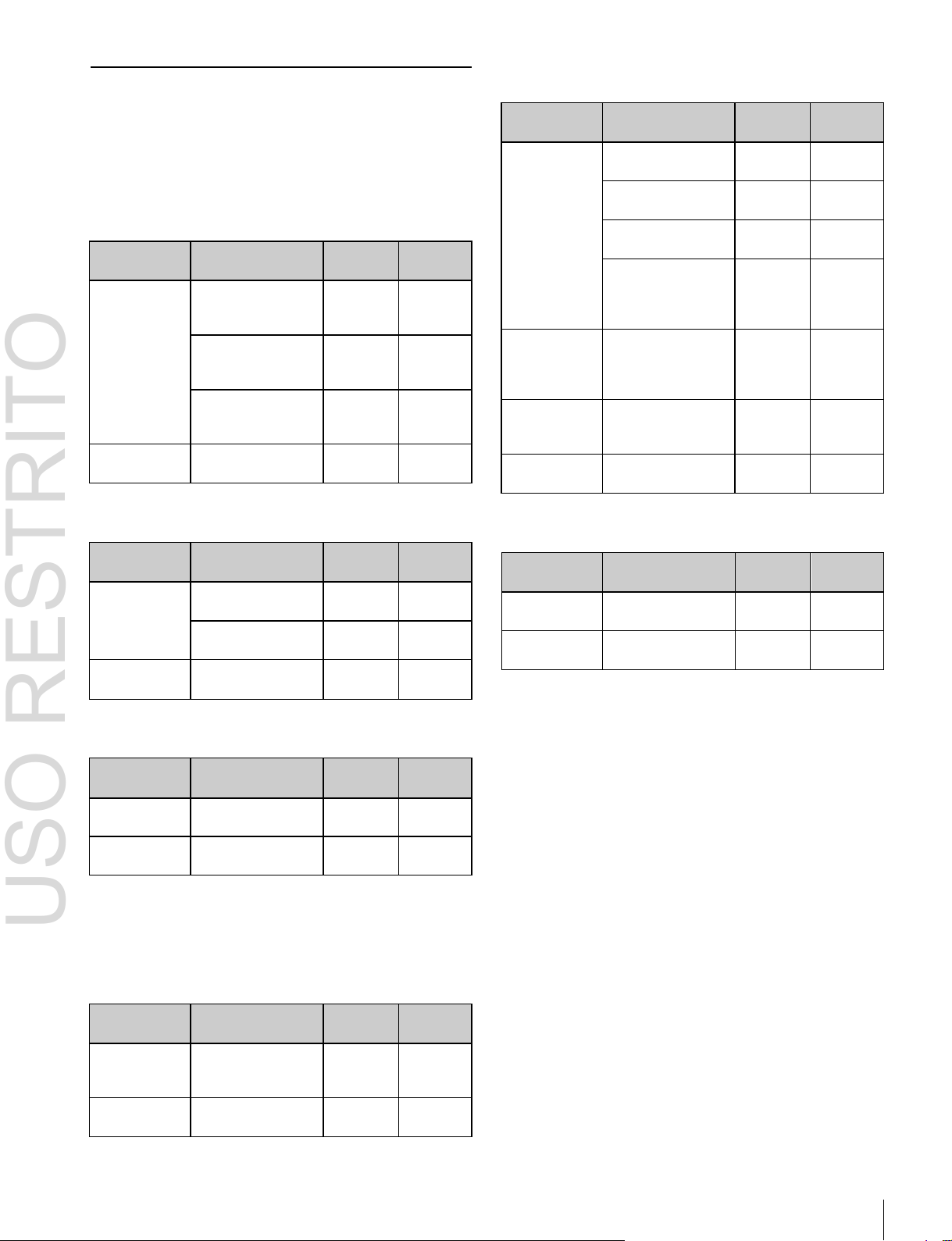
Changing the background
A background transition switches from the video currently
selected on the background A bus (the current video) to the
video selected on the background B bus (the new video).
Transition
In the default selection of flip-flop mode
background always switches in the direction from the A
bus to the B bus. When the transition completes, the crosspoint selections on the A and B buses are interchanged.
Background A Background B
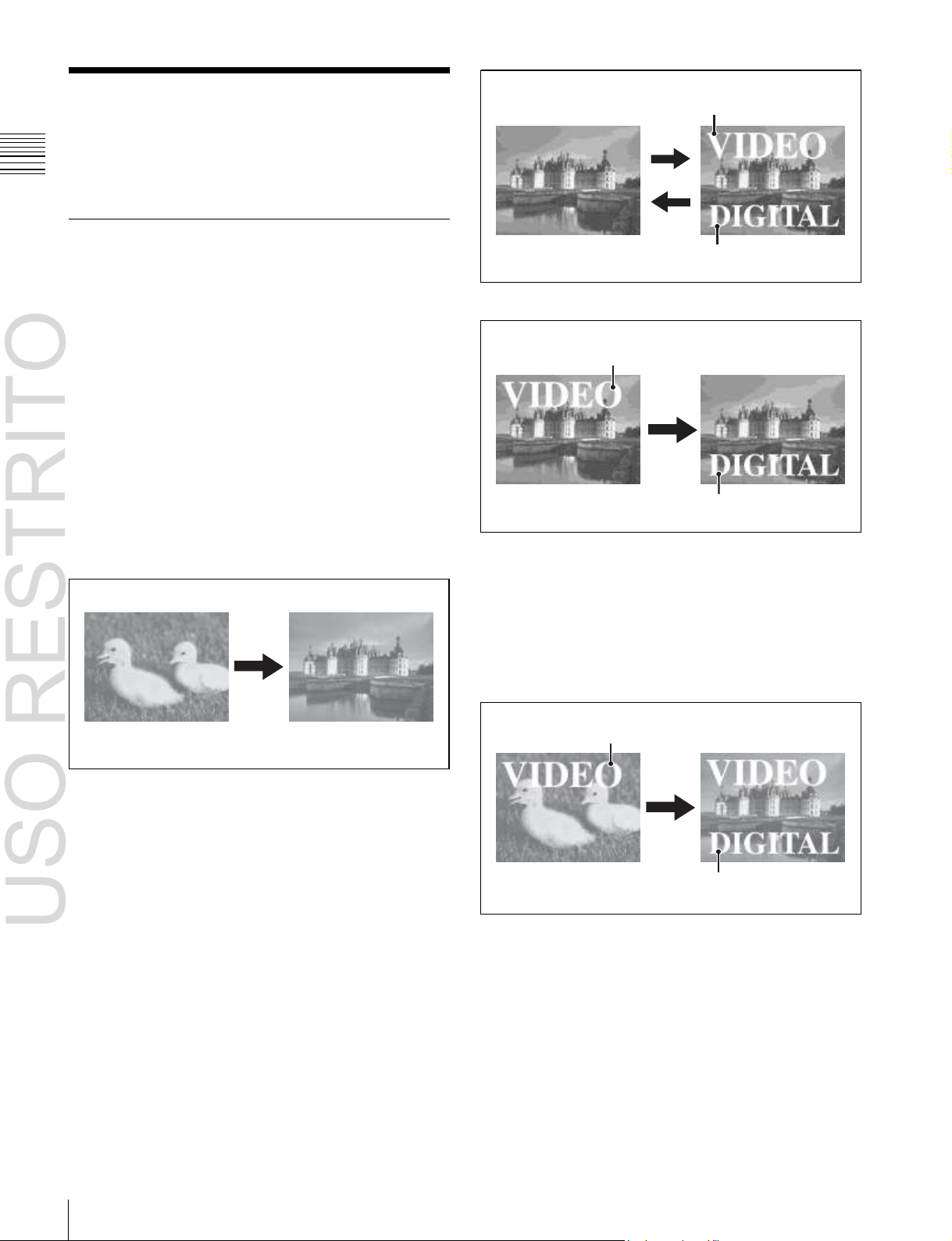
Inserting and deleting a key
You can insert one or more of the four keys (downstream
keys on the PGM/PST bank).
If you select a key which is already inserted, the transition
will delete the key.
A simultaneous combination of deleting and inserting keys
is also possible.
(1 p. 73), the
Key 1
Key 2
Insert
Delete
Inserting or deleting key 1 and key 2
Key 1
Transition
Key 2
Deleting key 1 and inserting key 2
Simultaneously changing the background
and keys
You can change one or more of the four keys (downstream
keys on the PGM/PST bank) and the background at the
same time.
Key 1
Changing the background and keys 1 and 2 simultaneously
Transition
Key 2

USO RESTRITO
Basic Video Processing 19
Chapter
1
Overview
Key 1
Key 3
Effect of a common transition
In the case shown in the previous illustration, carrying out
a common transition produces the following change in the
image.
Transition
Key 2 Key 4
Changing the background and keys 1 to 4 simultaneously
Selecting the transition type determines the way in which
the transition occurs. The following transition types are
available.
•
Mix
•
NAM (non-additive mix)
•
Super mix
•
Preset color mix (color matte)
•
Wipe
•
DME wipe
•
Clip transition
•
Cut
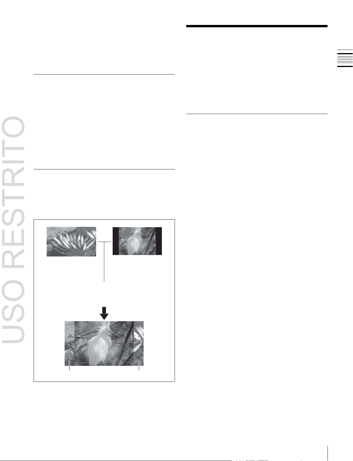
Transition type: Wipe
Same wipe is applied to
Effect of a common transition
background and key.
Effect with use of an independent key transition
The key is inserted with an independent key transition as
the background changes with a common transition,
providing the following result.
Transition type: Wipe
There are two modes of executing a transition: an auto
transition by button operation or a manual transition using
the fader lever. It is also possible to combine these two
modes.
Independent key transitions
In addition to common transitions, it is possible to carry
out independent transitions on the keyers of the M/E banks
and PGM/PST bank. These are called “independent key
transitions.”
By carrying out an independent key transition in
combination with a common transition, different transition
types can be used for the background and keys.
The following compares the independent key transition
with a common transition, taking a simultaneous change of
the background and key as an example.
Independent key
transition type: Wipe
Effect of a background transition and independent key transition
For details, see Chapter 3 “Signal Selection and
Transitions”
(1 p. 59).
Keys
Video used in the transition
A key is an effect in which a part of the background image
is replaced by an image or superimposed text. The signal
determining how the background is cut out is termed “key
source,” and the signal that replaces the cut-out part is
termed “key fill.” The system component responsible for
processing a key is referred to as a “keyer.”
For the four keyers on each switcher bank, you can use the
following key types (i.e., methods of processing the key
source).
Background A Background B Key to insert
•
Luminance key
•
Linear key
•
Color vector key
•
Chroma key
•
Key wipe pattern key
Different wipe patterns are
applied to the background
and key transitions.

USO RESTRITO
20
Basic Video Processing
Chapter
1
Overview
Key modifiers
You can apply borders and other modifiers to the edge of
the key image.
Masks
A mask allows a part of the image to be masked by the
background or a key. If unwanted holes occur in the
background, or if a key is not the desired shape, you can
correct the problem with a mask.
Resizer
This function allows you to apply effects, such as zoom,
movement, or aspect ratio change to a part of a created key.
You can use the following operations.
•
Two-dimensional transform of a key
•
Rotation of keys
•
Resizer interpolation settings
•
Resizer crop/border settings
•
Resizer effect settings (mosaic, defocus)
For details, see Chapter 4 “Keys”
Notes
Resizer and key edge cannot be used on some keyers.
For details, 1 “Keyers that support resizer/key edge”
(p. 79).
Wipes
A wipe is a transition from the current video stream to a
new video stream, using a wipe pattern.
Changing the background by means of a wipe is referred to
as a “background wipe,” and inserting or deleting a key
with a wipe is termed a “key wipe.”
There are two types of wipe: those that can be selected in
a common transition, and those that can be selected in an
independent key transition.
You can also specify the wipe direction, or set the pattern
position, applying various changes and modifiers to the
selected wipe pattern.
DME wipe patterns supported on the MVS-6520/6530/
3000A:
Slide, Squeeze, Split, Door, Flip tumble, Mirror,
Sphere, Character trail, Wave, Ripple, Page turn, Roll,
Frame in-out, Picture-in-picture, 2D trans, 3D trans,
Sparkle, Split slide, Mosaic, Defocus, Brick, and User
programmable DME
DME wipe patterns supported on the MVS-3000:
Slide, Squeeze, Door, Flip tumble, Frame in-out,
Picture-in-picture, Mosaic, and Defocus
You can also specify the wipe direction, or set the pattern
position, applying various changes and modifiers to the
selected DME wipe pattern.
Resizer DME wipes
Using the resizer, you can carry out key DME wipes.
For details, see Chapter 6 “DME Wipes”
(1 p. 111).
(1 p. 79).
Frame Memory
Frame memory is a function for using a still image or video
(frame memory clip) as material for editing.
You can create a still image by capturing a frame of input
video, or a clip by specifying a range of input video. The
created images and clips can be written to memory for
playback, editing, and output.
For details, see Chapter 7 “Frame Memory”
(1 p. 126).
Color Backgrounds
This function can be used to obtain color background
video.
Two color signals generated from the dedicated generators
can be switched or mixed, and then output.
For details, see “Color Background”
chapter 8.
(1 p. 146) in
Copy and Swap
For details, see Chapter 5 “Wipes”
DME Wipes
A DME wipe is a wipe transition that uses an image
transformation effect to change from one video image to
the next.
There are two types of DME wipe: those which can be
selected for a normal transition, and those which can be
selected for an independent key transition.
(1 p. 101).
This function can be used to copy and swap the settings
between switcher banks or between keyers.
The following settings can be copied or swapped.
•
Settings for the M/E and PGM/PST banks
•
Keyer settings
•
Wipe settings in a transition control block
•
Wipe settings in an independent key transition
•
DME wipe settings in a transition control block
•
DME wipe settings in an independent key transition
•
Matte color settings (color 1, color 2, and how to
compose them)
•
Color settings
USO RESTRITO
Creation of Special Effects and Management of Data and Operations 21
Chapter
1
Overview
•
DME channel settings
•
Format converter input settings (copy only)
•
Format converter output settings (copy only)
For details, see “Copy and Swap”
8.
(1 p. 147) in chapter
Color Corrector
The color corrector enables video signal color correction
(black balance/white balance adjustment, gamma
correction, knee correction, etc.).
The color corrector includes the following adjustments.
•
Input video processing
•
Primary color correction
•
RGB clip
For details, see “Configuring the Color Corrector”
(1 p. 347) in chapter 19.
Side Flags
The term “side flags” refers to the areas to left and right of
an image with aspect ratio 4:3 embedded within a 16:9
frame, when these areas are filled with a separate image
selected from the utility bus.
Image to fill the side flag
areas (selected from
utility bus)
Side flag area
For details, see “Side Flags”
Turn on the side
flag function
Input source with 4:3
aspect ratio
Side flag area
(1 p. 154) in chapter 9.
Creation of Special
Effects and Management
of Data and Operations
This section introduces functions used for creation of
special effects, control of external devices or switcher
operations, and data management.
Digital Multi Effects (DME)
When used with the switcher, DME allows you to add
three-dimensional effects such as image movement,
rotation, magnification and shrinking, as well as a wide
variety of special effects.
Each channel can be used on its own or in combination
with other channels, which allows you to create advanced
effects with more complexity.
The following types of DME special effects are available.
•
Edge effects: Border, Crop, Beveled Edge, Key Border,
Art Edge, Flex Shadow, Drop Shadow
•
Effects for entire image: Defocus, Blur, Multi Move
•
Effects for video image: Sepia, Mono, Posterization,
Solarization, Nega, Contrast, Mosaic, Mask, Sketch,
Metal, Dim and Fade, Glow
•
Freeze effects
•
Nonlinear effects: Wave, Mosaic Glass, Flag, Twist,
Ripple, Rings, Broken Glass, Flying Bar, Blind, Split,
Split Slide, Mirror, Multi Mirror, Kaleidoscope, Lens,
Circle, Panorama, Page Turn, Roll, Cylinder, Sphere,
Explosion, Swirl, Melt, Character Trail
•
Lighting effects: Lighting, Spotlighting
•
Recursive effects: Trail, Motion Decay, Keyframe
Strobe
•
Background color
•
Separate Sides (effects for front and back sides)
•
Signal inversion (Invert effect)
•
Key density adjustment
•
Key source selection
Global Effects
Global effects are special effects created by combining the
images of successive channels. Combiner, Brick, and
Shadow global effects are available.
For details, see Chapter 10 “DME Operations”
(1 p. 157).
USO RESTRITO
22
Creation of Special Effects and Management of Data and Operations
Chapter
1
Overview
Controlling External Devices
Snapshots
You can operate the system while controlling the
following types of external device:
• Devices supporting P-Bus (Peripheral II protocol)
•
Devices supporting GPI
•
VTRs
•
Disk recorders (Sony disk 9-pin protocol and video disk
communications protocol)
•
Extended VTRs (Abekas A53 protocol)
For details about the devices that can be connected,
consult your Sony representative.
You can also control an external device by registering
timeline keyframes beforehand.
For details, see Chapter 11 “External Devices”
(1 p. 226).
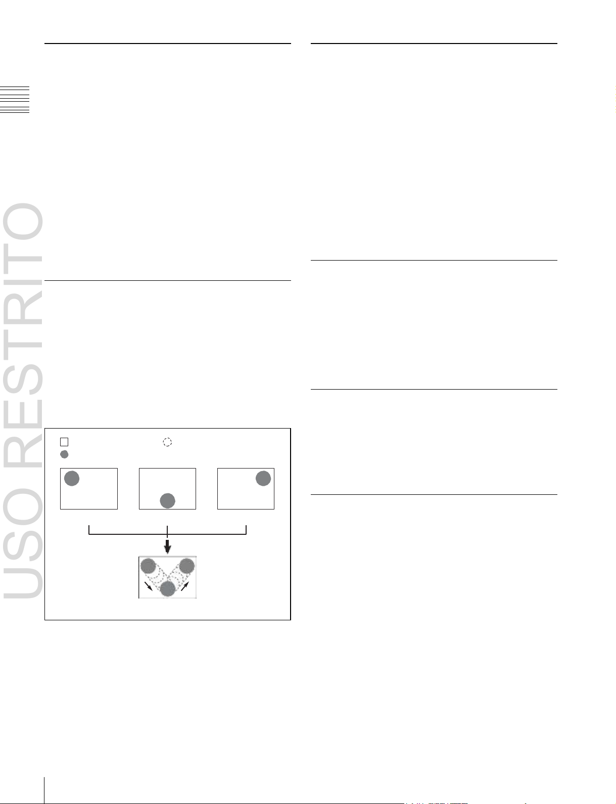
Keyframes
A keyframe represents an instantaneous state of an image;
it can be saved in a register and recalled for reuse. By
arranging a number of keyframes on the time axis, and
interpolating between successive keyframes, you can
create a “keyframe effect” in which there is a continuous
change from each keyframe to the next.
The following figure shows three keyframes created with
a wipe pattern (the circle) in different positions. This is
interpolated to create the effect shown.
Background A
Background B
Keyframe 1
Example of keyframes and effect execution
Keyframe 2
Execute effect
Interpolated images
Keyframe 3
You can save the sequence of keyframes representing a
single effect in a register. Then by recalling this register,
you can replay the same effect.
For details, see Chapter 12 “Keyframes”
(1 p. 239).
The term “snapshot” refers to a function whereby the
various settings required to apply a particular effect to an
image are saved in a register as a set of data, for recall as
required, to recover the original state.
Snapshots are divided as follows.
•
Snapshots applying to a particular region (functional
block of the switcher or DME)
•
Master snapshot
•
Key snapshot
•
Wipe snapshot
•
DME wipe snapshot
For details, see Chapter 13 “Snapshots”
(1 p. 267).
Utilities
The utility function refers to a function whereby you can
assign an arbitrary action or a shortcut for a frequently
used menu to a particular button, then instantly recall the
action or menu by pressing the button.
For details, see “Utility Execution”
14.
(1 p. 276) in chapter
Shotboxes
The term “shotbox” refers to a function whereby for each
specified region
(1 p. 239) any snapshot or keyframe
effect can be recalled simultaneously.
For details, see “Shotbox”
(1 p. 277) in chapter 14.
Macros
The term “macro” refers to the function whereby a
sequence of signal selections and other operations on the
control panel is saved as data in memory (macro register),
so that it can be recalled as required to automatically
execute the same sequence of operations.
The individual control panel operations constituting a
macro are termed “events.”
Macros also provide the following functions.
Menu macros
The term “menu macro” refers to the function whereby a
sequence of menu operations is saved as an event, so that
it can be recalled as required to automatically execute the
same sequence of operations.

USO RESTRITO
Setup 23
Chapter
1
Overview
Macro timelines
By recording macro recalls and execute actions on a
timeline, in the same way as for keyframes in an effect,
you can automatically execute them in a sequence.
Macro attachments
Macro attachment is a function whereby a macro register
is assigned to a control panel button or a particular position
of a fader lever, linking the execution of the button
function or a fader lever operation with a macro execution.
Router/tally setup (Router/Tally)
For details, see Chapter 22 “Router Interface and Tally
Setup”
(1 p. 373).
User setup (User Setup)
For details, see Chapter 23 “User Setup”
(1 p. 378).
For details, see Chapter 15 “Macros”
(1 p. 281).
File Operations
You can save register data, including setup information
and snapshot information, as a file on a local disk or
removable disk, and recall it as required.
Regarding frame memory, it is possible to capture image
data stored in an external device into frame memory. You
can also convert the format of image data in frame memory
into a different format and save it in an external device.
For details, see Chapter 16 “Files”
(1 p. 302).
Setup
Various settings are required, in order to operate the
switcher, control panel, DME, external devices, and so on,
connected together in a single system.
This is referred to as “setup,” and you can carry out the
setup operations from the Engineering Setup menu
(hereinafter, the Setup menu). The settings are grouped
under the following headings.
System setup (System)
For details, see Chapter 17 “System Setup”
(1 p. 313).
Panel setup (Panel)
For details, see Chapter 18 “Control Panel Setup”
(1 p. 325).
Switcher setup (Switcher)
For details, see Chapter 19 “Switcher Setup”
(1 p. 345).
DME setup (DME)
For details, see Chapter 20 “DME Setup”
(1 p. 363).
DCU setup (DCU)
For details, see Chapter 21 “DCU Setup”
(1 p. 366).
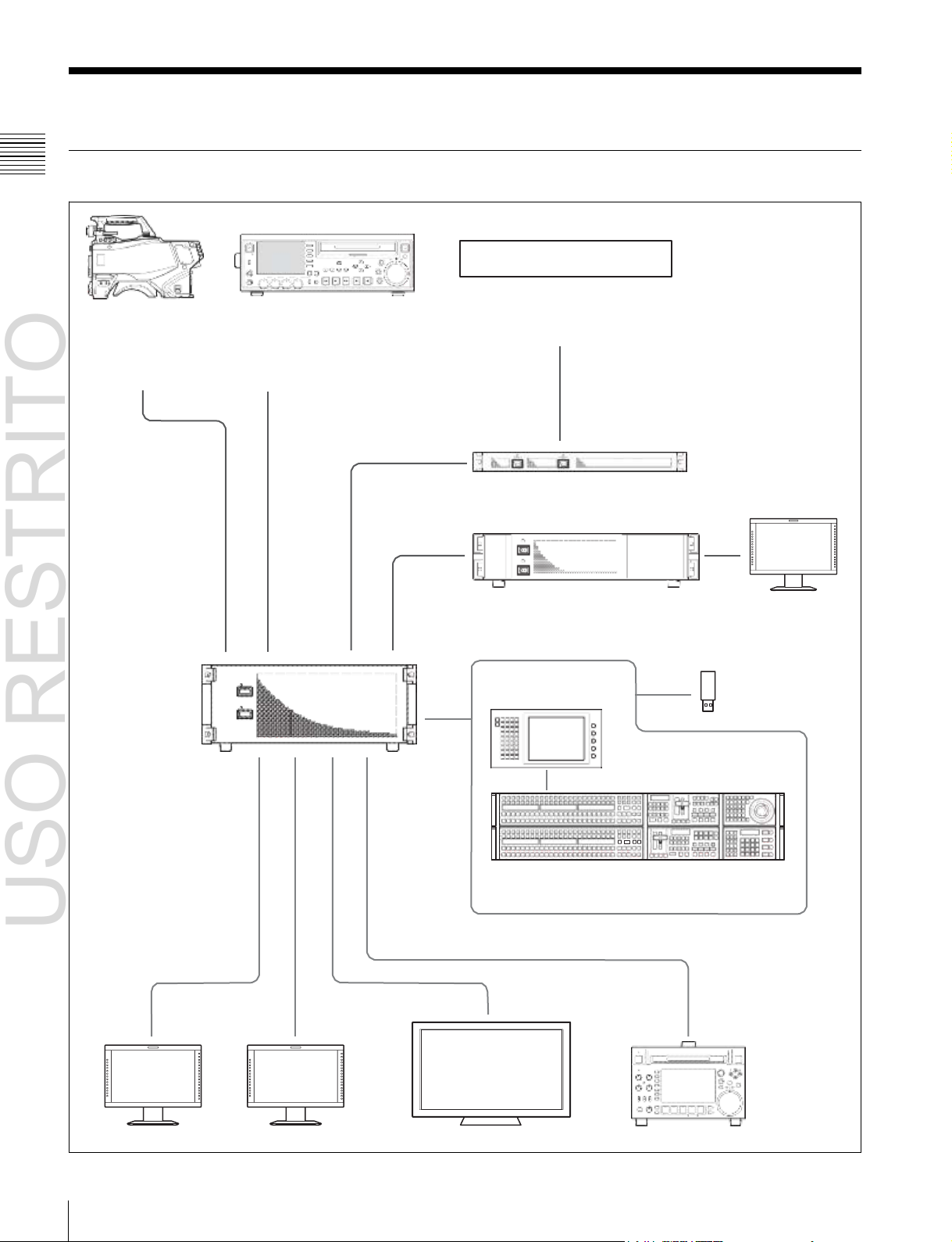
USO RESTRITO
24
System Configuration
Chapter
1
Overview
System Configuration
System Configuration Example
MVS-6520/6530/
3000A/3000 Multi
Format Switcher
Processor
ACCE
SS
NE
T
W
O
R
K
L
OC
AL
REMOTE
LEVEL
PHONES CH 1 CH 2 CH 3 CH 4
VARIABLE
F1
F
ME
2
ARK
NU
1
F
IN
3
F4 CHAPTE R
F5 EXPAND
SUB
THUMB
CLIP
NAIL
SET RESET
PAGE DISPLAY
CLIP ESSENCE
MENU MARK
SHIFT
PREV PLAY NEXT STOP REC SHUTTLE
KEY INHI
R
E
C
P
R
E
S
E
T
PB
TOP F REV F FWD END STANDBY
M
MARK2
EJECT
V
A
O
R
U
T
JOG
Audio mixer
Camera Playback VTR
MKS-2700/8700 Device Control Unit
POWER A
POWER B
MVE-8000A/9000
Multi Format DME Processor
ICP-6511
Menu Panel
ICP-6520/6530/3000/3016 Control Panel
Preview monitor Program monitor Monitor for multi viewer Recording VTR
a)
Menu can also be operated by connecting an external monitor in place of the menu panel.
b)
ICP-6520 diagram shown.
a)
DME monitor
Removable disk
b)

USO RESTRITO
System Configuration 25
Chapter
1
Overview
Connection Example
MVS-6520/6530/3000A/3000 Multi Format Switcher Processor
MVS
ICP-6520/6530/3000/3016 Control Panel
MVS
a)
MVS-6520/3000A/3000 diagram shown.
b)
ICP-6520 diagram shown.
In addition to these devices, a DCU (MKS-8700/2700) or DME processor (MVE8000A/9000) can be used to extend the system.
AC power supplies
U
b)
DEVICE 1
DVI-D
DVI cable
USB cable
a)
ICP-6511 Menu Panel
AC power adaptor
LAN cable (straight type)
DVI-D
DEVICE
AC power
supplies
U

USO RESTRITO
26
Names and Functions of Parts of the Control Panel
Chapter
2
Names
and
Functions
of
Parts
Name
ICP-6520 Control Panel
ICP-6530 Control Panel
ICP-3000 Control Panel
ICP-3016 Control Panel
Panel
configuration
Two rows
Three rows
Two rows
Two rows
Banks
M/E-1, PGM/PST
M/E-1, M/E-2, PGM/PST
M/E-1, PGM/PST
ME-1, PGM/PST
Keys
• When MVS-6520/
3000A/3000 (2M/E
processor) is
connected:
M/E-1: Key1 to Key4
P/P: DSK1 to DSK4
• When MVS-6530 (3M/E
processor) is
connected:
M/E-1: Key1 to Key4
P/P: DSK1 to DSK8
• When MVS-6520/
3000A/3000 (2M/E
processor) is
connected:
M/E-1: Key1 to Key4
P/P: DSK1 to DSK4
• When MVS-6530 (3M/
E processor) is
connected:
M/E-1, M/E-2: Key1 to
Key4
P/P: DSK1 to DSK8
• When MVS-6520/3000A/3000 (2M/E processor) is
connected:
M/E-1: Key1 to Key4
P/P: DSK1 to DSK4
• When MVS-6530 (3M/E processor) is connected:
M/E-1: Key1 to Key4
P/P: DSK1 to DSK8 (DSK5 to DSK8 insertion and
removal control from Flexi Pad)
Names and Functions of
Parts
Chapter
2
Names and Functions of Parts of the Control Panel
Specification differences for each system
configuration
In an MVS system, the number of available banks and keys
will differ depending on the control panel and switcher
processor configuration.
This manual describes operations and settings for an MVS6520/3000A and ICP-6520 configuration as an example.
For details about operational differences resulting from
different specifications, 1 “8-Keyer Operation” (p. 412).
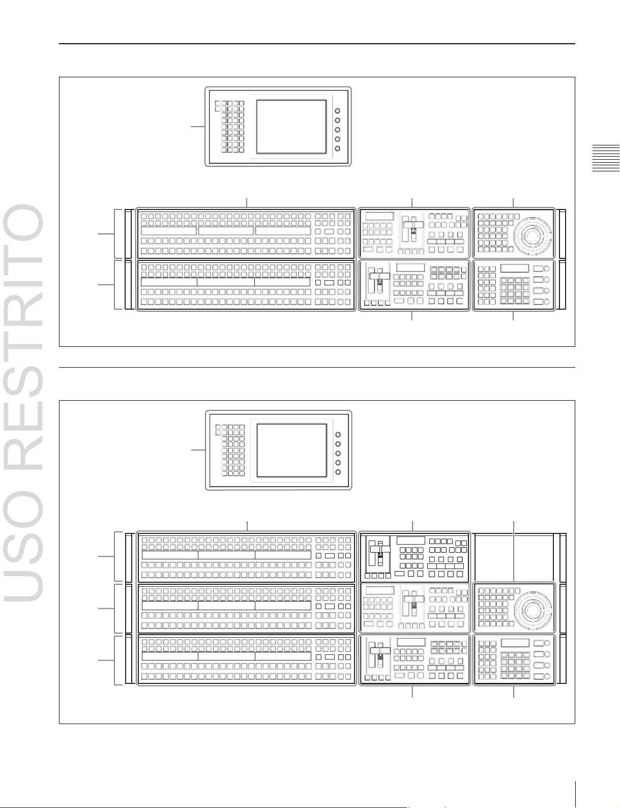
USO RESTRITO
Names and Functions of Parts of the Control Panel 27
Chapter
2
Names
and
Functions
of
Parts
ICP-6520 Control Panel Configuration
Menu panel
M/E-1
bank
PGM/PST
bank
(1
p. 42)
Cross-point control block (1 p. 29)
The menu panel is optional.
Transition control block
(M/E)
(1
p. 34)
Transition control block
(PGM/PST)
(1
p. 34)
Device control block
(1
Flexi Pad
p. 38)
(1
p. 40)
ICP-6530 Control Panel Configuration
Menu panel
M/E-1
bank
M/E-2
bank
PGM/PST
bank
(1
p. 42)
Cross-point control block
(1
p. 29)
The menu panel is optional.
Transition control block
(M/E)
(1
p. 34)
Transition control block
(PGM/PST)
(1
p. 34)
Device control block
(1
Flexi Pad
p. 38)
(1
p. 40)
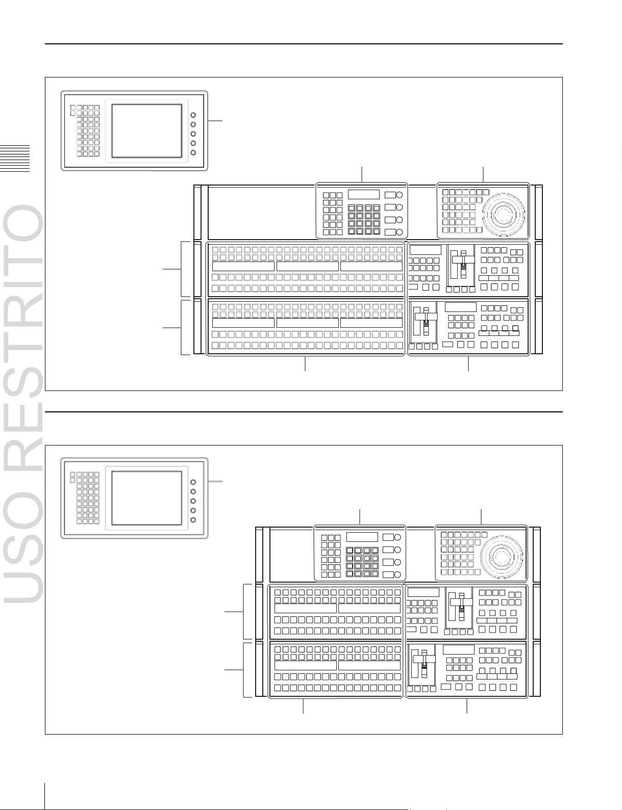
USO RESTRITO
28
Names and Functions of Parts of the Control Panel
Chapter
2
Names
and
Functions
of
Parts
ICP-3000 Control Panel Configuration
M/E-1 bank
PGM/PST bank
Menu panel
(1
p. 42)
Flexi Pad
Cross-point control block
(1
(1
p. 31)
p. 40)
The menu panel is optional.
Transition control block (1 p. 34)
Device control block
(1
p. 38)
ICP-3016 Control Panel Configuration
M/E-1 bank
PGM/PST bank
Menu panel
p. 42)
(1
Flexi Pad
Cross-point control block (1 p. 31)
(1
p. 40)
The menu panel is optional.
Transition control block (1 p. 34)
Device control block
(1
p. 38)
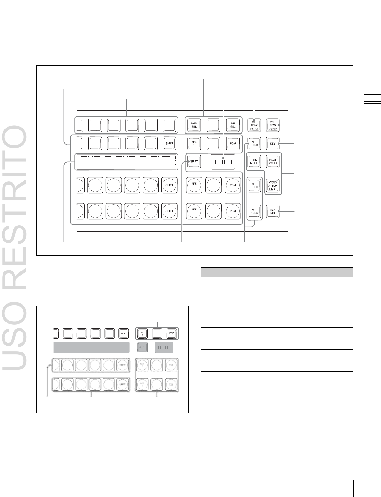
USO RESTRITO
Names and Functions of Parts of the Control Panel 29
Name
Description
2nd row
• Use this to select the cross-point of the
bus that is specified with the 1st row
buttons.
a) b)
• If the utility/shotbox function is selected
with the 1st row buttons, use this to
recall the register or to execute the
function.
Background A
row
Use this to select the signal as the
current background video on this M/E
bank or PGM/PST bank.
Background B
row
Use this to select the signal as the
background video after the transition on
this M/E bank or PGM/PST bank.
Reentry buttons
Use these to select the video created on
another bank as background A or B on
this bank or as the bus specified with the
1st row buttons.
For details, 1 “Selecting M/E reentry
input signals” (p. 60).
Chapter
2
Names
and
Functions
of
Parts
Cross-Point Control Block (ICP-6520/6530)
In the cross-point control block, you can select the signals
to be used in the M/E bank or PGM/PST bank.
a
Cross-point buttons
c
1st row
i
Source name displays
a
Cross-point buttons
These select the signals used for video processing on this
M/E bank or PGM/PST bank. Each row of buttons
corresponds to one or more signal buses within the
switcher.
2nd row
Reentry
buttons
e
M/E bank selection buttons
f
M/E bank display
d
Dedicated SHIFT button b XPT HOLD button
j
1ST ROW DSPLY button
k
2ND ROW DSPLY
button
l
KEY button
g
Macro buttons
h
AUX MIX button
Background
A row
Background
B row
Reentry
buttons
a) You can select the source signal of the key bus by selecting the cross-point
while holding down the button to which any of KEY1 to KEY4 or DSK1
to DSK4 is assigned in the 1st row.
b) You can select the image on the reverse side of the currently viewed DME
image by selecting the cross-point while holding down the button to which
any of DME1 V/K, DME2 V/K, or DME5 V/K to DME8 V/K is assigned

USO RESTRITO
30
Names and Functions of Parts of the Control Panel
Name
Description
PRE MCRO
(pre-macro)
Sets a macro attachment in pre-macro
mode.
When setting to macro-only mode, this
button is used in combination with the
user preference button on the menu
panel with the “Macro Only Set”
assignment. This mode can also be set
by pressing the [PRE MCRO] and [POST
MCRO] buttons simultaneously.
POST MCRO
(post-macro)
Sets a macro attachment in post-macro
mode.
When setting to macro-only mode, this
button is used in combination with the
user preference button on the menu
panel with the “Macro Only Set”
assignment. This mode can also be set
by pressing the [PRE MCRO] and [POST
MCRO] buttons simultaneously.
Chapter
2
Names
and
Functions
of
Parts
in the 1st row (DME1 V/K and DME2 V/K using MKS-6570 only, and
DME5 V/K to DME8 V/K using MVE-8000A/9000 only).
Cross-point button numbers
Cross-point buttons and reentry buttons are respectively
numbered
(1 p. 61)
.
Assigning signals to buttons
You can assign a signal to each button using the Setup
menu.
For details, 1 “Cross-Point Settings” (p. 329).
Visual indications on cross-point buttons
For details, 1 “Colors of lit cross-point buttons” (p. 63).
b
XPT HOLD (cross-point hold) button
These allow you to recall a keyframe or snapshot while
keeping the current cross-point selection unchanged.
Functions for these buttons vary depending on the
operation mode selected in the Setup menu.
For details, 1 “Setting the operation mode of the key bus
[XPT HOLD] button” (p. 357).
c
1st row
This selects a key bus, AUX bus, or function.
You can assign the following buses, functions, and buttons
in the Setup menu.
•
KEY1 to KEY4, DSK1 to DSK4, UTIL1, EXT DME1),
EDIT PVW, AUX1 to AUX24, FMS1, FMS2,
DME1 V/K2), DME2 V/K2), DME5 V/K to
DME8 V/K
•
Utility/shotbox function
•
Inhibit Set function
•
Cross-point hold function
•
[PRE MCRO], [POST MCRO], [MCRO ATTCH
3)
ENBL], [KEY], [1ST ROW DSPLY], [2ND ROW
DSPLY], [SHIFT] buttons
1) MVS-6520/6530/3000A only
2) MKS-6570 only
3) MVE-8000A/9000 only
For details about assignments, 1 “Assigning a Bus or
Function to 1st Row Buttons” (p. 340).
Utility/shotbox function
Assign the function of the [UTIL/SBOX] button, and use
for utility/shotbox operations.
When you turn on the button to which [UTIL/SBOX] is
assigned, the buttons in the cross-point control block will
be used for utility/shotbox operations.
To inhibit an operation, press the cross-point button for
which you want to inhibit operation while holding the
button to which [INH SET] is assigned.
Cross-point hold function
Assign the function of the [XPT HOLD] button to recall a
keyframe or snapshot while maintaining the selection
status of the current cross-point.
Valid for background A row and B row. It can also be used
for the following function blocks when configured in the
Setup menu.
•
Background A row and B row
•
Key bus
•
Utility bus
•
DME external video bus (MVS-6520/6530/3000A only)
d
Dedicated SHIFT button
This button has the following two functions.
Source name display shift button: When this button is
enabled, the source name display shows the shifted
signal name.
Bus shift button: When this button is enabled, it acts as a
shift button for all buses on this M/E (PGM/PST)
bank.
You can select the mode in the Setup menu.
e
M/E bank selection buttons
These interchange the settings of the entire switcher bank
with the settings of the selected M/E bank.
This applies to all the buttons in the cross-point control
block and the transition control block.
f
M/E bank display
This indicates the notional mix/effect bank name to which
the particular M/E bank is assigned, as a four-character
identifier.
g
Macro buttons
These enable macro attachments and select the macro
attachment mode.
For details, 1 “Executing a Shotbox Function with
Cross-Point Buttons in the 2nd Row” (p. 280).
Inhibit Set function
Assign the function of the [INH SET] button, and use to
inhibit button operations.
 Loading...