

Sony MVS-6500 System Startup Manual
MVS-6500 System
(SY)
4-448-461-11 (1)
Sony Corporation
Printed on recycled paper.
Printed in Japan
2012.09 32
© 2012
Multi Format Switcher System
MVS-6500 System
(With ICP-6520/6530 Control Panel)
MVS-6520 MVS-6530 ICP-6520 ICP-6530
ICP-6511 MKS-6550 MKS-6570
Startup Guide [English]
Software Version 1.00 and Later
1st Edition

NOTICE TO USERS
© 2012 Sony Corporation. All rights reserved. This
manual or the software described herein, in whole or
in part, may not be reproduced, translated or reduced
to any machine readable form without prior written
approval from Sony Corporation.
SONY CORPORATION PROVIDES NO
WARRANTY WITH REGARD TO THIS MANUAL,
THE SOFTWARE OR OTHER INFORMATION
CONTAINED HEREIN AND HEREBY EXPRESSLY
DISCLAIMS ANY IMPLIED WARRANTIES OF
MERCHANTABILITY OR FITNESS FOR ANY
PARTICULAR PURPOSE WITH REGARD TO THIS
MANUAL, THE SOFTWARE OR SUCH OTHER
INFORMATION. IN NO EVENT SHALL SONY
CORPORATION BE LIABLE FOR ANY
INCIDENTAL, CONSEQUENTIAL OR SPECIAL
DAMAGES, WHETHER BASED ON TORT,
CONTRACT, OR OTHERWISE, ARISING OUT OF
OR IN CONNECTION WITH THIS MANUAL, THE
SOFTWARE OR OTHER INFORMATION
CONTAINED HEREIN OR THE USE THEREOF.
Sony Corporation reserves the right to make any
modification to this manual or the information
contained herein at any time without notice.
The software described herein may also be governed
by the terms of a separate user license agreement.

Table of Contents
Overview
Introduction .................................................4
Names of Parts............................................ 5
MVS-6520/6530 Multi Format Switcher
Processor.............................................. 5
ICP-6520/6530 Control Panel....................... 8
ICP-6511 Menu Panel................................... 9
Connection
MVS-6500 System Configuration............. 10
Video Input/Output Systems....................... 10
Device Control Systems.............................. 11
Connecting Devices..................................12
MVS System Connection............................ 12
Peripheral Device Connection .................... 13
Assigning Signals to Subscreens................. 25
Setting Multi Viewer Tally Output ............. 26
Setting Tally............................................... 26
Setting Parallel Tally................................... 26
Setting Serial Tally...................................... 26
Assigning 8-Keyer Buttons...................... 36
Assigning Key 5 to Key 8 to 1st Row
Buttons............................................... 36
Assigning Key Selection Functions to Next
Transition Selection Buttons ............. 36
Setting the Startup State.......................... 37
Selecting the Startup Mode at Power On ....37
Customizing the User Default Settings....... 38
Saving Data to Removable Disk .............. 39
Setting Up a Removable Disk for Use ........ 39
Saving/Recalling User Settings on Removable
Disks .................................................. 39
Setting Simple Connection of AUX Bus
Remote Panel .....................................41
Basic Image Creation Operations
Preparation
Preparation Procedure .............................15
Turning Power On/Off............................... 16
Opening Menus........................................... 18
Configuring the Network .......................... 19
Setting Signal Formats.............................20
Setting the Signal Format............................ 20
Setting the Screen Aspect Ratio.................. 21
Assigning Signals to Cross-Point
Buttons................................................21
Setting the Signal Name.............................. 21
Assigning Pair Signals to Cross-Point
Buttons............................................... 22
Assigning Output Signals ........................23
Setting Monitor Outputs ............................. 23
Using Multi Viewer .................................... 24
Setting Multi Viewer Output ...................... 24
Configuring Multi Viewer .......................... 24
Video Switching (Transitions) ................. 43
Types of Transitions (Mix/NAM/Wipe/DME
Wipe) ................................................. 43
Names of Parts in the Control Panel ........... 44
Video Transitions using Cuts...................... 44
Video Transitions using Wipes or Mixes.... 45
Saving DME Wipe Settings in a DME Wipe
Snapshot............................................. 48
Setting Picture-in-Picture (DME Wipe)...... 48
Saving/Recalling a DME Wipe Snapshot... 49
Inserting Titles (Keys) .............................. 51
What is a Key? ............................................ 51
Entering Titles using Luminance Keys....... 51
Composing Images using Chroma
Keys..................................................... 54
Table of Contents
3

Overview
Overview
Introduction
The Startup Guide (this document) describes the basic
settings and operations to begin using the MVS system.
For details about settings and operations, refer to the
User’s Guide.
4
Introduction
Names of Parts
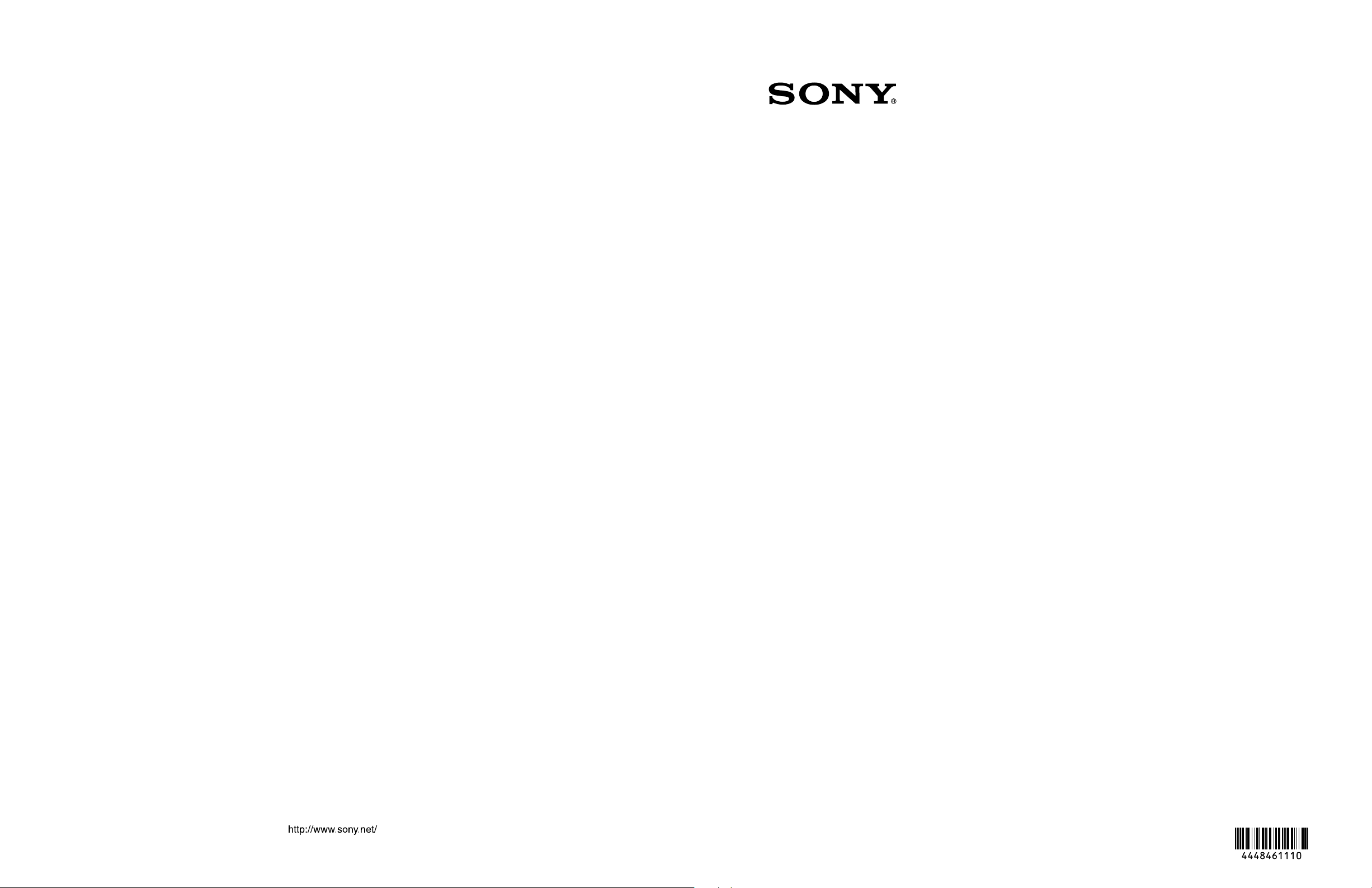
MVS-6520/6530 Multi Format Switcher Processor
Rear panel: MVS-6520
Slots 1 to 5
Slots 6 to 8
Slots 1 to 5
c PRIMARY INPUTS 1 to 32 connectors
1IN2 3 4 5 6 7 8 9 10 11 12 13 14 15 16
1IN2 3 4 5 6 7 8 9 10 11 12 13 14 15 16
OUT
1
2 3 4 5 6 7 8 9 10 11 12 13 14 15 16
a -AC IN A and B connectors
b U terminal
1
1
16
17
2
32
33
3
48
1
4
16
17
5
32
Overview
Slots 6 to 8
d OUTPUTS 1 to 16 connectors
e TALLY/GPI IN 1 to 18 and TALLY/
GPI OUT 1 to 48 connectors
f SERIAL TALLY connector
SERIAL TALLY REMOTE 4 REMOTE 3 REMOTE 2 REMOTE 1
TALLY/GPI IN13-18 OUT33-48 TALLY/GPI IN7-12 OUT17-32 TALLY/GPI IN1-6 OUT1-16 UTIL(FM)FM DEVICE
REF IN UTIL(SW)MVS REMOTE S2 REMOTE S1 UTIL(SCU)S-BUS
g REMOTE 1 to 4 connectors i FM DEVICE connector
m MVS connector l REMOTE S1 and S2
connectors
n UTIL (SW) connector
k UTIL (SCU) connector
o REF INPUT connectors
h UTIL (FM) connector
6
7
8
j S-BUS connector
Names of Parts
5
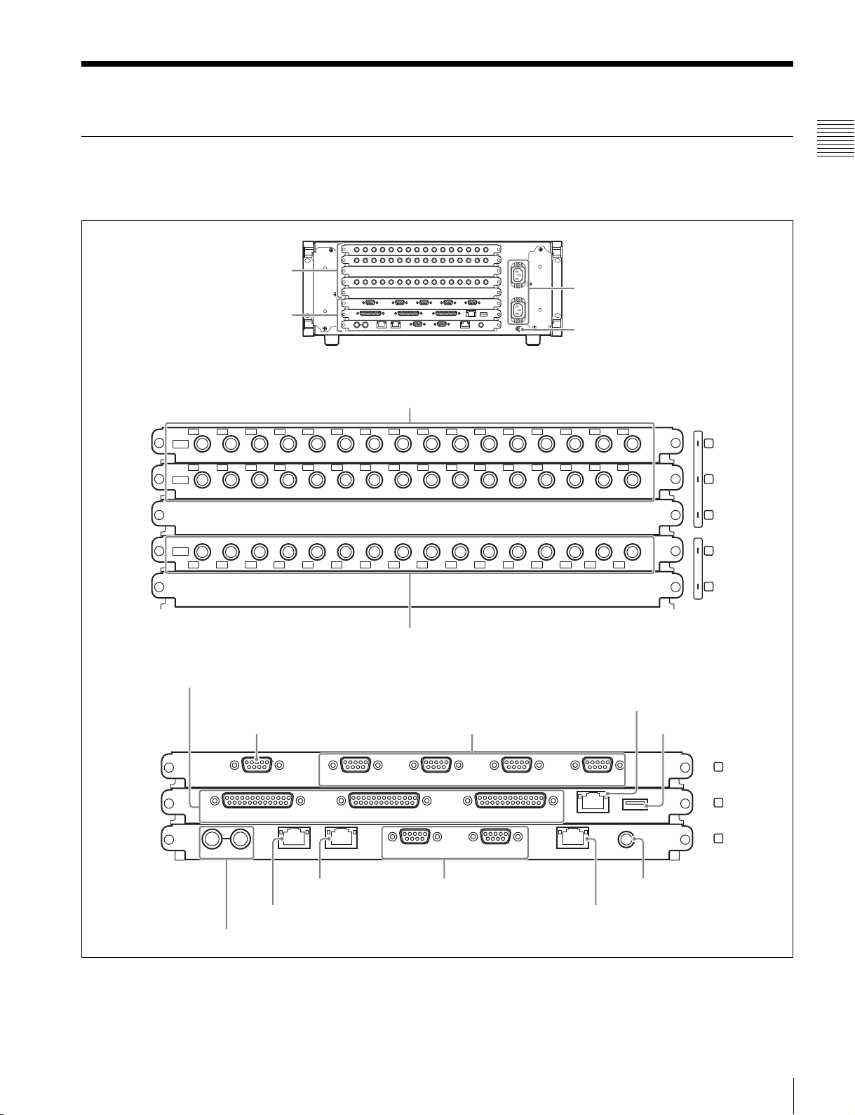
Rear panel: MVS-6530
Overview
Slots 1 to 5
a -AC IN A and B connectors
Slots 1 to 5
Slots 6 to 8
Slots 6 to 8
b U terminal
c PRIMARY INPUTS 1 to 48 connectors
1IN2 3 4 5 6 7 8 9 10 11 12 13 14 15 16
1IN2 3 4 5 6 7 8 9 10 11 12 13 14 15 16
1IN2 3 4 5 6 7 8 9 10 11 12 13 14 15 16
OUT
1
2 3 4 5 6 7 8 9 10 11 12 13 14 15 16
OUT
1
2 3 4 5 6 7 8 9 10 11 12 13 14 15 16
d OUTPUTS 1 to 32 connectors
e TALLY/GPI IN 1 to 18 and TALLY/
GPI OUT 1 to 48 connectors
f SERIAL TALLY connector
g REMOTE 1 to 4 connectors i FM DEVICE connector
1
1
16
17
2
32
33
3
48
1
4
16
17
5
32
h UTIL (FM) connector
SERIAL TALLY REMOTE 4 REMOTE 3 REMOTE 2 REMOTE 1
TALLY/GPI IN13-18 OUT33-48 TALLY/GPI IN7-12 OUT17-32 TALLY/GPI IN1-6 OUT1-16 UTIL(FM)FM DEVICE
REF IN UTIL(SW)MVS REMOTE S2 REMOTE S1 UTIL(SCU)S-BUS
m MVS connector l REMOTE S1 and S2
n UTIL (SW) connector
o REF INPUT connectors
a - AC IN (AC power input) A and B connectors
(3-pin)
Connect to 100 V to 240 V AC power supply with the
optional AC power cords.
The unit is equipped with two power supplies. When A or
B power supply is connected, unit operation can proceed.
b U (signal ground) terminal
Connect to the system ground.
6
7
8
j S-BUS connector
connectors
k UTIL (SCU) connector
c PRIMARY INPUTS
1 to 32 connectors (BNC-type)
1 to 48 connectors (BNC-type)
1)
: MVS-6520
1)
: MVS-6530
These connectors allow you to input up to 32 or up to 48
serial digital video signals to the MVS-6520 or MVS-6530
system, respectively.
6
Names of Parts
d OUTPUTS
1 to 16 connectors (BNC-type)
1 to 32 connectors (BNC-type)
1)
: MVS-6520
1)
: MVS-6530
These connectors output serial digital signals. You can
assign them as program output, preview output, AUX
output, and so on.
Make output assignments on the MVS-6500 system
control panel.
• Returning to the S-Bus, tally data created by this unit on
the basis of data received from other devices
• Switching the cross-points of a routing switcher from the
control panel
• Switching the cross-points of a switcher from the remote
panel
• Displaying on the control panel source names set on a
routing switcher
Overview
Types of output
signal
Re-Entry Source OUTPUTS 1 to 16 OUTPUTS 1 to 24
Aux Bus OUTPUTS 1 to 16 OUTPUTS 1 to 24
Output/MV/FC/
DME
Configurable connectors
MVS-6520 MVS-6530
OUTPUTS 1 to 16
(FC: 15, 16
combination only)
OUTPUTS 1 to 32
(FC: 15, 16 and 31,
32 combinations
only)
For details about output signals and settings, refer to the
User’s Guide.
e TALLY/GPI IN (tally/ general purpose interface
input) 1 to 18 and TALLY/GPI OUT (tally/ general
purpose interface output) 1 to 48 connectors (D-sub
25-pin)
Output tally data created with the control panel of the
MVS-6500 system (open collector).
These connectors can also be used as GPI output ports.
You can also input trigger signals as GPI inputs.
Input and output settings are made on the control panel of
the MVS-6500 system.
f SERIAL TALLY connector (D-sub 9-pin,
RS-422A)
Output tally data created with the control panel of the
MVS-6500 system.
g REMOTE 1 to 4 connectors (D-sub 9-pin, RS-
422A)
Connect devices supporting Sony 9-pin VTR, VDCP
(Video Disk Communications Protocol), or P-Bus
(Peripheral II Protocol) protocols.
h UTIL (FM) (utility (frame memory data))
connector (RJ-45 compliant)
Intended for future expansion.
i FM (frame memory) DEVICE connector (USB 2.0
compliant)
This connector is for attaching an external HDD for frame
memory.
2)
k UTIL (SCU) (utility (SCU)) connector (RJ-45
compliant)
Intended for future expansion.
l REMOTE S1 and S2 connectors (D-sub 9-pin, RS-
422A compliant)
These connectors are used to operate the MVS-6500
system from external devices or editing control systems
such as the BVE-9100.
Define the types of the connected devices on the control
panel.
m MVS (multi format video switcher) connector
(RJ-45 compliant)
Connect to an ICP-6520/6530 control panel.
For details about connecting a DCU and MVE-8000A/
9000 multi format DME processor, refer to the User’s
Guide.
n UTIL (SW) (utility (SW)) connector (RJ-45
compliant)
Intended for future expansion.
o REF INPUT (reference video input) connectors
(BNC-type)
1)
If you wish to synchronize this unit to an external reference
signal, input the reference signal. For an HDTV system,
input an HD tri-level sync signal, black burst signal, or
analog sync signal. For an SDTV system, input a black
burst signal or analog sync signal.
The two connectors have a loop-through configuration.
Signal input to one connector can be output from the other
connector. If you will not be using the loop-through
output, be sure to terminate the unused connector with the
supplied 75 ohm terminator.
1) Attach the cable connected to the BNC-type connectors to the rack or other
support so there is no load on the connector. There is a risk of damage to
the BNC-type connectors and cable.
2) For information about devices that can be connected, contact your Sony
representative.
j S-BUS connector (BNC-type)1)
Connect this connector with a BNC cable to an S-Bus data
link via a T bridge.
Connecting devices such as IXS series routing switchers
and MKS-8080/8082 AUX bus remote panels via an S-Bus
data link enables the following kinds of control.
Names of Parts
7

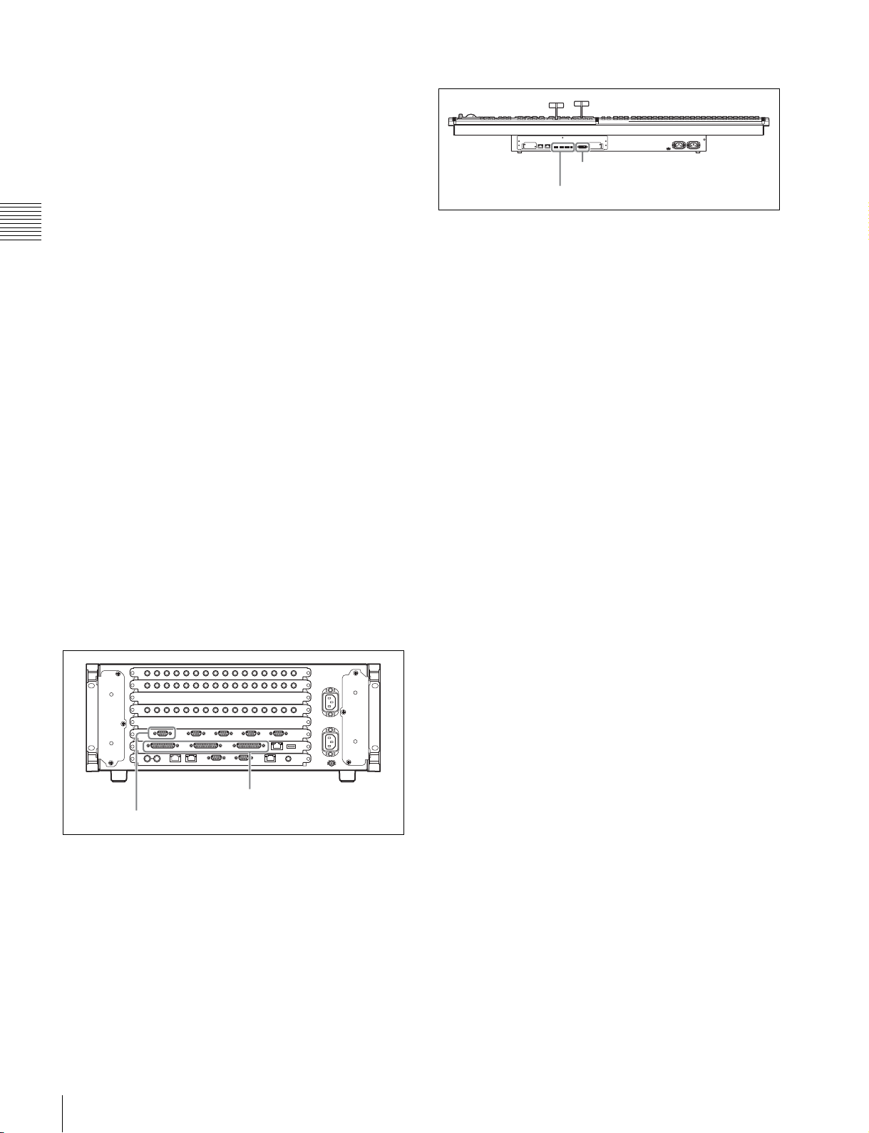
ICP-6520/6530 Control Panel
Rear panel
Overview
UTIL MVS DVI-D OUTDEVICE
f -AC IN A and B connectors
e U terminal
44321
b MVS connector
a UTIL connector
a UTIL (utility) connector (RJ-45 compliant)
Intended for future expansion.
b MVS (multi format video switcher) connector (RJ-
45 compliant)
Connect to the MVS-6520/6530.
For details about connecting a DCU and MVE-8000A/
9000 multi format DME processor, refer to the User’s
Guide.
c DEVICE 1 to 4 connectors (USB 2.0 compliant,
USB Type-A)
Connect to an ICP-6511 or USB device.
d DVI-D connector
Connect to an ICP-6511 or external monitor.
1)
1)
e U (signal ground) terminal
Connect to the system ground.
c DEVICE 1 to 4 connectors
d DVI-D connector
f - AC IN (AC power input) A and B connectors
(3-pin)
Connect to 100 V to 240 V AC power supply with the
optional AC power cords.
The unit is equipped with two power supplies. When A or
B power supply is connected, unit operation can proceed.
1) For information about devices that can be connected, contact your Sony
representative.
8
Names of Parts
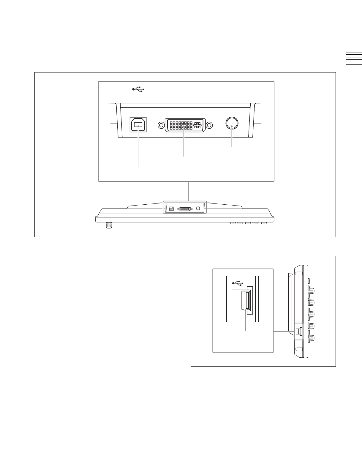
ICP-6511 Menu Panel
The menu panel is optional.
Bottom panel
DEVICE
a DEVICE connector
DVI-D
IN
b DVI-D connector
Overview
12V
!
c DC IN connector
a DEVICE connector (USB 2.0, USB Type-B)
Connect to the DEVICE 1 connector of the ICP-6520/
6530.
b DVI-D connector
Connect to the DVI-D output of the ICP-6520/6530.
c DC IN connector
Connect to the 12V DC connector of the supplied AC
adaptor.
Side panel
DEVICE connector
DEVICE connector (USB 2.0, USB Type-A)
In general, connect to a USB memory device, and input
and output files.
Names of Parts
9
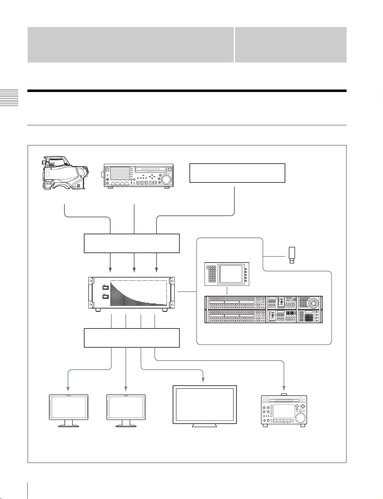
Connection
MVS-6500 System Configuration
Connection
Video Input/Output Systems
F1
ACCESS
NETWORK
LOCAL
REMOTE
LEVEL
PHONES
CH 1 CH 2 CH 3 CH 4
F2
F3
F4
F5
PAGEDISPLAY
VARIABLE
REC
PRESET
PB
CHAPTER
SUB
EXPAND
CLIP
CLIP
MENU
PREV NEXTPLAY STOP
KEY INHI
SHIFT
TOP
Camera Playback VTR
Video signal inputs
MVS-6520/6530
Multi Format
Switcher
Video signal outputs
THUMB
NAIL
ESSENCE
MARK
F REV F FWD
EJECT
VAR
MARK1
MENU
OUTIN
SET
RESET
JOG
MARK2
REC
SHUTTLE
END
STANDBY
Character generator
ICP-6511
Menu Panel
Removable
disk
ICP-6520/6530 Control Panel
Program monitorPreview monitor Monitor for multi viewer
Recording VTR
In addition to these devices, a DCU (MKS-8700/2700) or DME (MVE-8000A/9000) can be used to extend the system.
For more information, refer to the User’s Guide.
10
MVS-6500 System Configuration

Device Control Systems
ACCESS
NETWORK
LOCAL
REMOTE
LEVEL
PHONES
CH 1 CH 2 CH 3 CH 4
VARIABLE
REC
PRESET
PAGEDISPLAY
PB
F1
F2
F3
F4
CHAPTER
EXPAND
F5
KEY INHI
SHIFT
MENU
SUB
THUMB
SET
CLIP
NAIL
CLIP
ESSENCE
MENU
MARK
PREV NEXTPLAY STOP
TOP
F REV F FWD
RESET
END
STANDBY
EJECT
VAR
MARK1
OUTIN
JOG
MARK2
REC
SHUTTLE
VTRs and DDRs
Control devices connected using Sony 9-pin VTR, VDCP, or
P-Bus protocols
(RS-422A)
REMOTE 1 to 4
REMOTE S1 and S2
MVS-6520/6530
Multi Format
Switcher
MVSS-BUS
AUX bus control devices and editors
(RS-422A)
ICP-6511 Menu Panel
ICP-6520/6530 Control Panel
Connection
Removable
disk
Other devices on S-Bus data link
MKS-8080 AUX Bus Remote Panel
1 2 3 4 5 6 7 8 9 10 11 12 13 14 15 16 17 18 19 20 21 22
KEY X-HOLD DEST M/E 1 M/E 2 M/E 3 P/P
MKS-8082 AUX Bus Remote Panel
1 2 34 5 6 7 8 910111213141516
12345678910111213141516
17 18 19 20 21 22 23 24 25 26 27 28 29 30 31 32
a)
ASSIGN
23 24 25 26 27 28 29 30 31 32
AUX BUS REMOTE PANEL MKS-8080
a)
AUX BUS REMOTE PANEL MKS-8082
ASGN DEST LEVEL RTR
KEY
M/E1M/E2M/E
SELECTOR
XPT
LOCK
CLEAR
HOLD
(CHOP)
P/P
3
a) The MKS-8080/8082 can also be connected directly to
the switcher.
MVS-6500 System Configuration
11
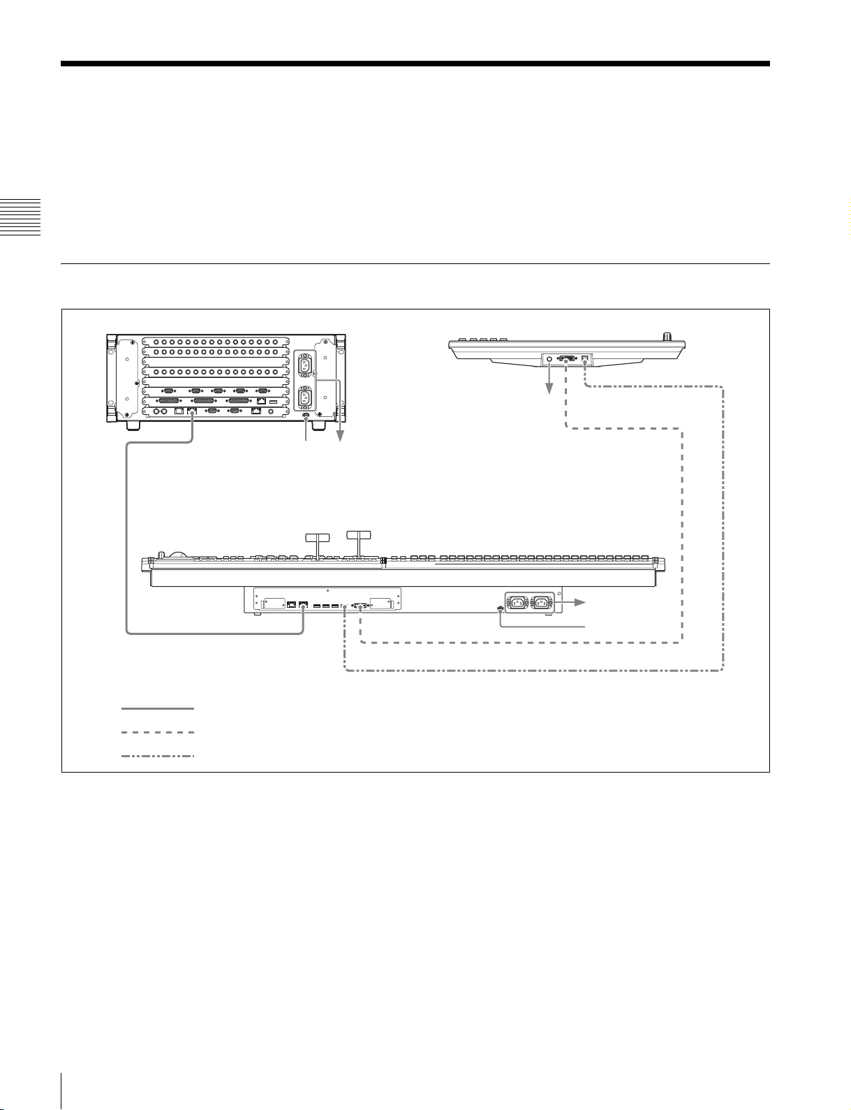
Connecting Devices
This section describes the connection procedure for the
following system configuration as an example.
• MVS-6520 Switcher Processor
(with MKS-6550 Format Converter Board and MKS6570 Digital Multi Effect Board installed)
• ICP-6520 Control Panel
Connection
MVS System Connection
MVS-6520 Switcher Processor ICP-6511 Menu Panel
MVS
U
AC power supplies
ICP-6520 Control Panel
• ICP-6511 Menu Panel
• Cameras for recording (4)
• VTRs for playback (2)
• Character generator (1)
• Video monitors (2)
• Monitor for multi viewer (1)
DEVICE
AC adaptor
DVI -D
MVS
LAN cable (straight type)
DVI cable
USB cable
1
Connect the power supply.
Switcher processor
a Connect the U terminal to the system ground.
b Connect the ~AC IN A and B connectors to the 100
V to 240 V AC power supplies using power cords
(not supplied).
Control panel
a Connect the U terminal to the system ground.
b Connect the ~AC IN A and B connectors to the 100
V to 240 V AC power supplies using power cords
(not supplied).
DVI -D
DEVICE 1
AC power
supplies
U
Menu panel
a Connect the supplied AC adaptor to the DC IN
connector, then connect the AC adaptor using a
power cord (not supplied).
2
Connect the switcher processor and control panel.
a Connect the MVS connector of the switcher
processor and the MVS connector of the control
panel using a LAN cable.
12
Connecting Devices
3
Connect the control panel and menu panel.
a Connect the DVI-D connector of the control panel
and the DVI-D connector of the menu panel using
the DVI cable supplied with the menu panel.
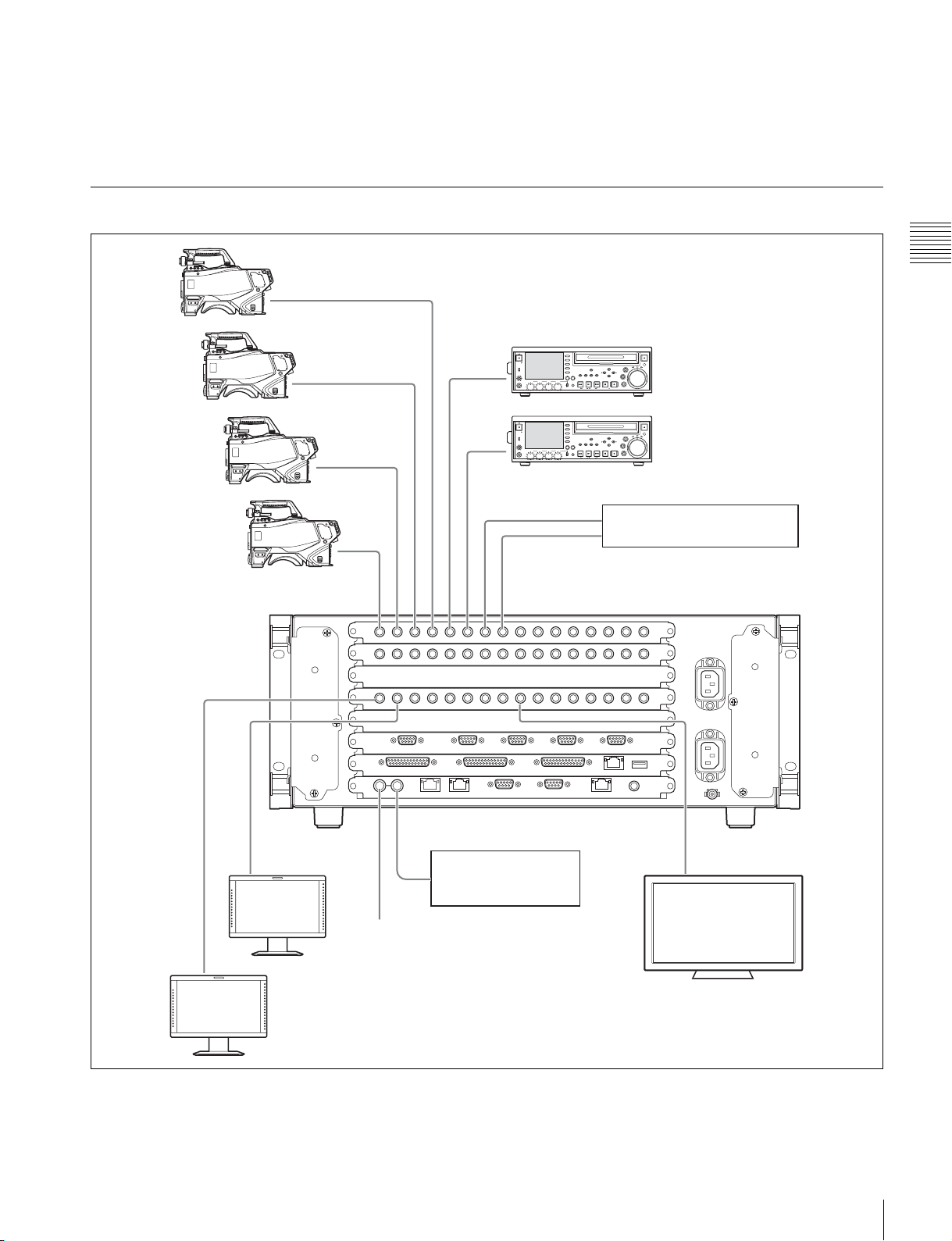
Peripheral Device Connection
b Connect the DEVICE 1 connector of the control
panel and the DEVICE connector on the bottom of
the menu panel using the USB cable supplied with
the menu panel.
Connection
OUTPUTS 1
PRIMARY INPUTS 1 2 3 4 5 6 7 8
2
ACCESS
NETWORK
LOCAL
REMOTE
LEVEL
PHONES
ACCESS
NETWORK
REMOTE
LEVEL
PHONES
CH 1 CH 2 CH 3 CH 4
LOCAL
CH 1 CH 2 CH 3 CH 4
PAGEDISPLAY
VARIABLE
REC
PRESET
PB
PAGEDISPLAY
VARIABLE
REC
PRESET
PB
Video signal
Key signal
F1
F2
F3
F4
F5
F1
F2
F3
F4
F5
CHAPTER
EXPAND
KEY INHI
SHIFT
TOP
CHAPTER
EXPAND
KEY INHI
SHIFT
TOP
MENU
SUB
THUMB
SET
RESET
CLIP
NAIL
CLIP
ESSENCE
MENU
MARK
PREV NEXTPLAY STOP
F REV F FWD
MENU
SUB
THUMB
SET
RESET
CLIP
NAIL
CLIP
ESSENCE
MENU
MARK
PREV NEXTPLAY STOP
F REV F FWD
EJECT
VAR
MARK1
OUTIN
JOG
MARK2
REC
SHUTTLE
END
STANDBY
EJECT
VAR
MARK1
OUTIN
JOG
MARK2
REC
SHUTTLE
END
STANDBY
Character generator
REF INPUT
75 ohm terminator
REF INPUT OUTPUTS 9
Reference signal
generator
Connecting Devices
13
Connection
1
Connect devices to the PRIMARY INPUTS of the
switcher processor.
a Connect the cameras for recording.
In this example, connect four cameras to
PRIMARY INPUTS 1 to 4.
b Connect the playback VTRs.
In this example, connect two VTRs to PRIMARY
INPUTS 5 and 6.
c Connect the character generator.
In this example, connect to PRIMARY INPUTS 7
and 8.
2
Connect devices to the OUTPUTS of the switcher
processor.
a Connect the video monitors.
In this example, connect two monitors to
OUTPUTS 1 and 2.
b Connect the monitor for multi viewer.
In this example, connect to OUTPUTS 9.
3
Connect reference signals to the REF INPUT
connectors of the switcher processor.
a Connect one REF INPUT connector to a reference
signal generator.
b Terminate the other REF INPUT connector using
the supplied 75 ohm terminator.
External monitor connection
DVI-D connector
DEVICE connector
Connect the DVI-D connector of the control panel and the
DVI-D connector of the external monitor using a DVI
cable.
If using a touch panel, connect the DEVICE connector of
the control panel and the USB connector of the external
monitor using a USB cable.
If using a mouse, connect the mouse to the DEVICE
connector of the control panel using a USB cable.
For details about connecting monitors, contact your Sony
representative.
To use the tally
Set the tally output, using either the SERIAL TALLY
connector or the TALLY connector (parallel tally) of the
switcher processor
TALLY connector (GPI IN/OUT connector)
SERIAL TALLY connector
To use an external monitor for menu
operations
Instead of the dedicated MVS system ICP-6511 menu
panel, you can connect an external monitor and operate the
menus from a touch panel or by mouse control.
14
Connecting Devices
Preparation
Preparation Procedure
This section describes the setup required before operation
in the MVS system.
Turn on the power (1 p. 16)
m
System settings
Configure the network (1 p. 19)
m
Set the signal format (1 p. 20)
m
Signal settings
Assign input signals (1 p. 21)
m
Assign output signals (1 p. 23)
m
Other settings
Make the following system configuration and other
settings, as required.
Preparation
• Configure multi viewer (1 p. 24)
•Set tally (1 p. 26)
• Assign buttons required for 8-keyer operation
(MVS-6530 only) (1 p. 36)
• Set startup mode (1 p. 37)
• Save data to removable disk (1 p. 39)
• Set simple connection of AUX bus remote panel
(1 p. 41)
Preparation Procedure
15
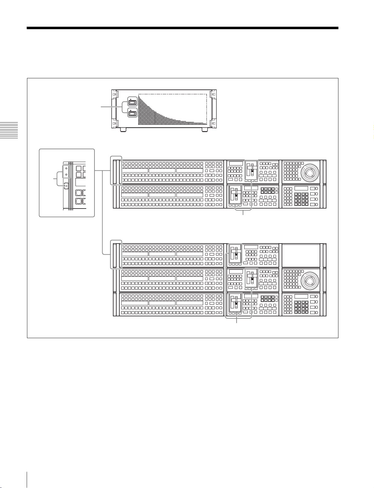
Turning Power On/Off
After connecting the system, turn on the power using the
following procedure.
1
Preparation
2
MVS-6520/6530
Switcher Processor
ICP-6520 Control Panel
1
Set the POWER A and B switches of the switcher
processor to ON (“?” side).
When the switcher processor is turned on, the status
indicators for supplies A and B light green.
2
Check that the status indicators on the control panel
are lit green, then press the POWER switch.
3
ICP-6530 Control Panel
3
16
Turning Power On/Off
The POWER switch mark “1” lights green.
The control panel boots in approximately one minute,
and the top menu list appears on the menu panel
screen.
While the system is accessing the local disk or frame
memory external HDD, the indicator on the menu page
number button lights red.
Check to make sure the indicator is not lit before
turning off the power.
Indicator on the menu page
number button
(ICP-6520 control panel display. The ICP-6530 also
has an [M/E2] button.)
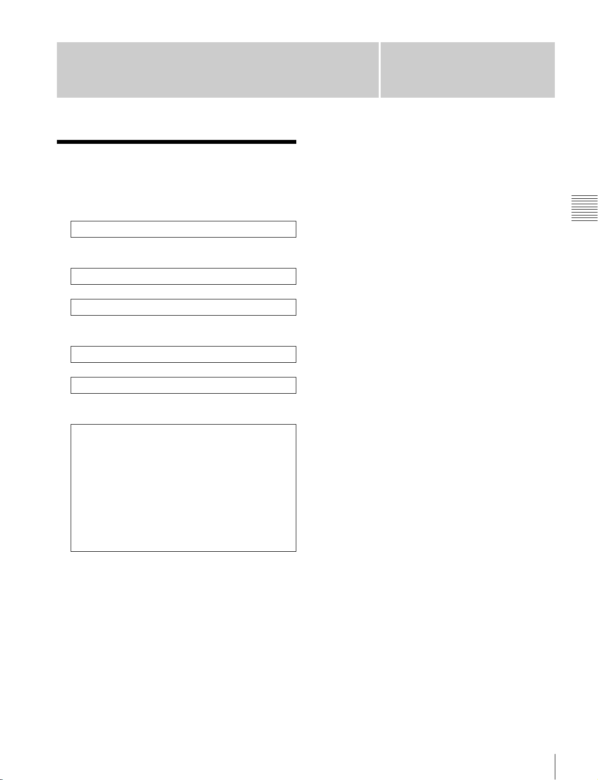
3
Pull the fader lever down from top to bottom.
Fader lever
When “Non Sync” or “Sync” appears at the top and
bottom stops of the fader lever (non-sync state), the
fader lever movement and transitions do not match.
Pull the fader level from top to bottom to release nonsync state.
Notes
Remove all USB flash memory and other removable
disks before turning off the power.
2
Shut down the control panel.
Press the menu page number button and display the top
menu window, then press the [Shutdown] button.
Menu page
number button
Shutdown button
Preparation
4
Turn on the power of other devices in the system.
Screen saver and panel sleep mode
If no operation is performed for a given time, the menu
display screen saver starts. The brightness of all indicators
and displays on the control panel also dims.
For details about settings, refer to the User’s Guide.
To turn the power off
1
On the menu screen, check that the local disk is not
being accessed.
A “local disk” refers to the internal flash memory drive
in a control panel.
(ICP-6520 control panel display. The ICP-6530 also
has an [M/E2] button.)
Turning Power On/Off
17
Preparation
A shutdown confirmation message appears.
Press [Yes] to commence shutdown. The process is
completed when the menu screen goes completely
black.
Check that the POWER switch indicator “1” on the
control panel has gone out.
Notes
You can forcibly turn off the power to the control
panel without following the normal shutdown
procedure by pressing and holding the POWER switch
for five seconds or longer. If you force shutdown,
settings data may not be saved.
3
Set the POWER A and B switches of the switcher
processor to OFF (“a” side).
Memo
You can also open the top menus using the top menu
selection buttons in the menu panel.
Top menu selection buttons
2
Select a menu.
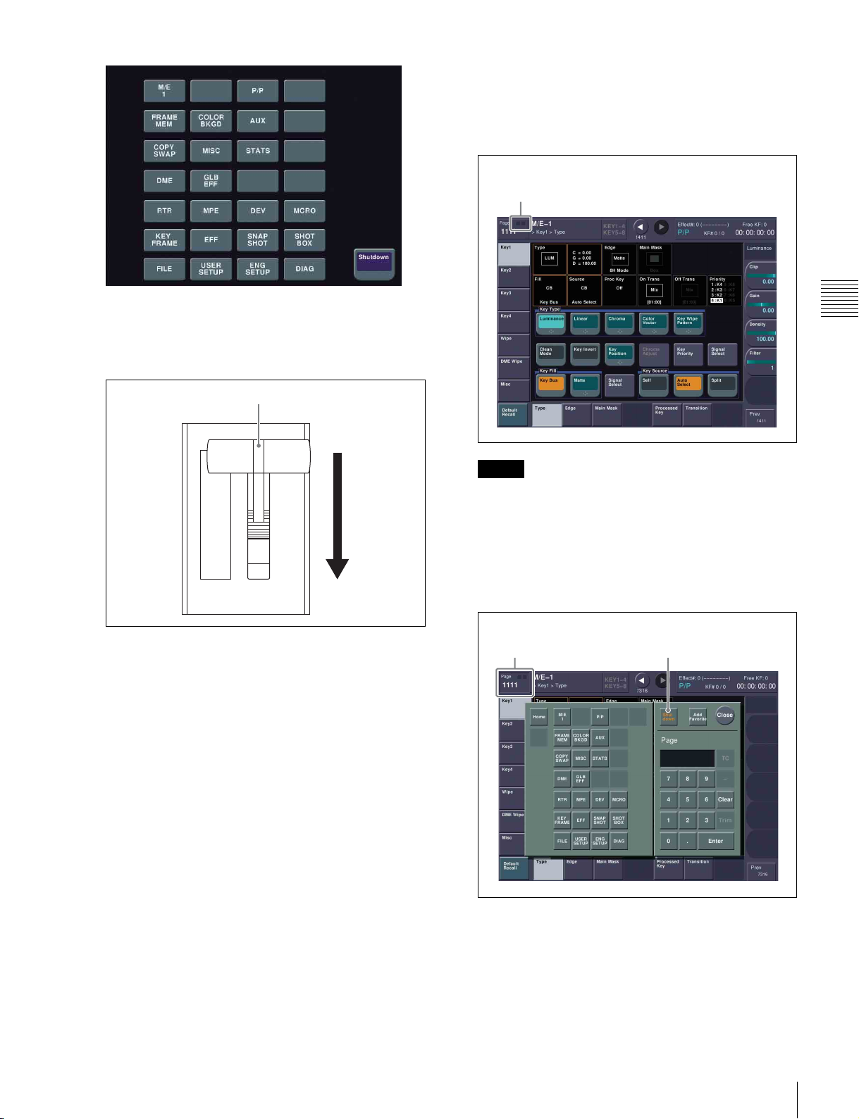
Opening Menus
In the MVS system, basic operations and system setup can
be done using the menu.
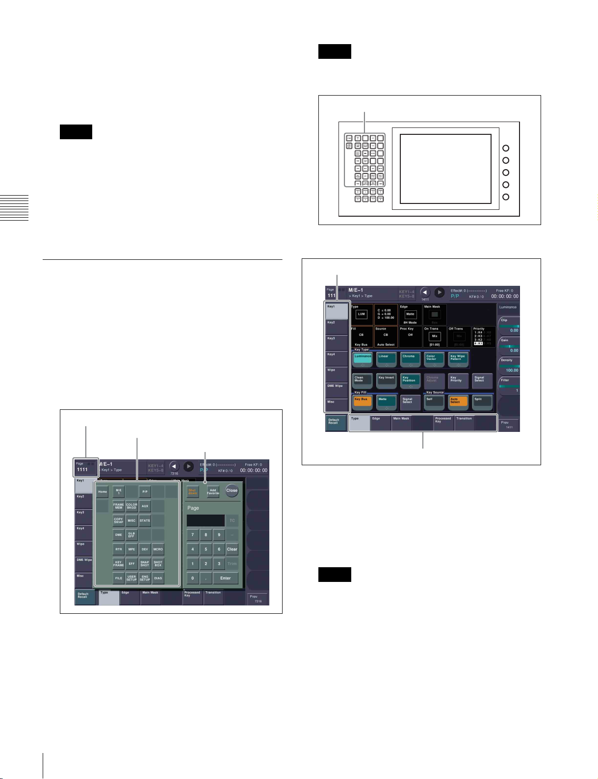
This section describes how to open the “M/E-1 >Key1
>Type menu (1111)” as an example. Other menus can be
opened using the same procedure.
For details about menu operations, refer to the User’s
Guide.
1
Recall the top menu (top level in menu hierarchy).
Menu page number button
Top menu selection buttons
Top menu window
VF buttons
HF buttons
a Select a submenu (level 2 in the menu hierarchy)
using VF buttons on the left edge.
In this example, select [Key1].
b Select a submenu (level 3 in the menu hierarchy)
using HF buttons on the bottom edge.
In this example, select [Type].
The M/E-1 >Key1 >Type menu appears.
18
Turning Power On/Off
Memo
You can also open the menu by entering the page
number “1111” in the top menu window.
a Press the menu page number button.
The top menu window appears.
b Press a top menu selection button.
In this example, press [M/E1].
 Loading...