

Page 1

MVS-6000 System
(With CCP-9000 Series Center Control Panel)
User’s Guide
Multi Format Switcher System
Volume 1 [English]
1st Edition
Software Version 8.00 and Later
Page 2

NOTICE TO USERS
© 2009 Sony Corporation. All rights reserved. This
manual or the software described herein, in whole or in
part, may not be reproduced, translated or reduced to
any machine readable form without prior written approval
from Sony Corporation.
SONY CORPORATION PROVIDES NO WARRANTY
WITH REGARD TO THIS MANUAL, THE SOFTWARE
OR OTHER INFORMATION CONTAINED HEREIN AND
HEREBY EXPRESSLY DISCLAIMS ANY IMPLIED
WARRANTIES OF MERCHANTABILITY OR FITNESS
FOR ANY PARTICULAR PURPOSE WITH REGARD TO
THIS MANUAL, THE SOFTWARE OR SUCH OTHER
INFORMATION. IN NO EVENT SHALL SONY
CORPORATION BE LIABLE FOR ANY INCIDENTAL,
CONSEQUENTIAL OR SPECIAL DAMAGES,
WHETHER BASED ON TORT, CONTRACT, OR
OTHERWISE, ARISING OUT OF OR IN CONNECTION
WITH THIS MANUAL, THE SOFTWARE OR OTHER
INFORMATION CONTAINED HEREIN OR THE USE
THEREOF.
Sony Corporation reserves the right to make any
modification to this manual or the information contained
herein at any time without notice.
The software described herein may also be governed by
the terms of a separate user license agreement.
Page 3

<Organization of This User’s Guide>
The User’s Guide for this system comprises Volumes 1 to 3.
Volume 1
This book. For the contents of this volume, see “Table of Contents” at the front.
Chapter 1 MVS-6000 Functions
Chapter 2 Menus and Control Panel
Chapter 3 Signal Selection and Transitions
Chapter 4 Keys
Chapter 5 Wipes
Chapter 6 DME Wipes
Chapter 7 Frame Memory
Chapter 8 Color Backgrounds, Copy and Swap, and Other Settings
Chapter 9 Color Corrector
Chapter 10 Special Functions
Appendix (Volume 1)
• Wipe Pattern List
• DME Wipe Pattern List
• Resizer DME Wipe Pattern List
• Menu Tree
Index
Volume 2
The volume comprises the following chapters.
Chapter 11 DME Operations
Chapter 12 External Devices
Chapter 13 Keyframe Effects
Chapter 14 Snapshots
Chapter 15 Utility/Shotbox
Chapter 16 Macros
Chapter 17 Files
Appendix (Volume 2)
• SpotLighting
• Functional Differences With Models of DME
• Macro File Editing Rules
• About the Macro Attachment List Display
• Menu Operations Not Recorded in a Menu Macro
Index
Volume 3
The volume comprises the following chapters.
Chapter 18 System Setup (System)
Chapter 19 Control Panel Setup (Panel)
Chapter 20 Switcher Setup (Switcher)
Chapter 21 DME Setup (DME)
Chapter 22 DCU Setup (DCU)
3
Page 4

Chapter 23 Setup Relating to Router Interface and Tally (Router/Tally)
Chapter 24 Simple Connection of the MKS-8080/8082 AUX Bus Remote
Panel
Chapter 25 DIAGNOSIS
Appendix (Volume 3)
• Data Saved by [Setup Define] and [Initial Status Define]
• Error Messages
Index
4
Page 5

Table of Contents
Chapter 1 MVS-6000 Functions
Introduction ..................................................................................................14
Features of the MVS-6000 Multi Format Switcher System......................16
Basic Video Processing.................................................................................18
Transitions.............................................................................................18
Keys.......................................................................................................22
Wipes.....................................................................................................23
DME Wipes...........................................................................................23
Frame Memory ......................................................................................24
Color Backgrounds................................................................................24
Copy and Swap......................................................................................24
Video Process........................................................................................25
Color Corrector......................................................................................25
Side Flags ..............................................................................................25
Simple P/P Software..............................................................................26
Creation of Special Effects and Management of Data and Operations...27
Digital Multi Effects (DME) .................................................................27
External Devices....................................................................................28
Keyframes .............................................................................................28
Snapshots...............................................................................................29
Utility.....................................................................................................30
Shotbox..................................................................................................30
Macros ...................................................................................................30
Files .......................................................................................................31
Setup ..............................................................................................................32
Chapter 2 Menus and Control Panel
Names and Functions of Parts of the Control Panel .................................34
Example Control Panel Configuration ..................................................34
Cross-Point Control Block ....................................................................36
Transition Control Block.......................................................................37
Device Control Block (Joystick)...........................................................42
Keyframe Control Block .......................................................................43
Numeric Keypad Control Block............................................................46
5Table of Contents
Page 6

Auxiliary Bus Control Block.................................................................49
Menu Control Block..............................................................................50
Memory Card/USB Adaptor Block.......................................................51
“Memory Stick”/USB Connections Block............................................52
Key Control Block (MKS-8035 Key Control Module, Option) ...........54
Device Control Block (MKS-8031TB Trackball Module, Option) ......58
Device Control Block (MKS-8036A Search Dial Module, Option) .....61
Utility/Shotbox Control Block (MKS-8033 Utility/Shotbox Module,
Option) .......................................................................................65
Downstream Key Control Block (MKS-8032 DSK Fader Module,
Option) .......................................................................................66
Basic Menu Operations................................................................................68
Menu Organization................................................................................68
About the Top Menu List ......................................................................68
Accessing Menus...................................................................................68
Displaying a Menu ................................................................................74
Interpreting the Menu Screen................................................................75
Menu Operations ...................................................................................77
Switching Between the Main Menu Site and Subsidiary Menu Site ....89
Shortcut Menu .......................................................................................89
Chapter 3 Signal Selection and Transitions
Table of Contents
6
Video Processing Flow .................................................................................94
Signal Selection .............................................................................................96
Basics of Signal Selection .....................................................................96
Bus Selection.........................................................................................97
Signal Assignment and Selection..........................................................98
Signal Name Display...........................................................................102
Transitions...................................................................................................103
Selecting the Next Transition..............................................................103
Transition Types..................................................................................103
Procedure for Basic Transition Operation...............................................106
Key Priority Setting....................................................................................109
Setting the Key Priority in the Transition Control Block....................109
Setting the Key Priority by a Menu Operation....................................111
Display of the Key Output Status and Key Priority............................113
Selecting the Transition Type by a Menu Operation..............................114
Super Mix Settings .....................................................................................115
Color Matte Settings...................................................................................116
Page 7

Executing a Transition...............................................................................119
Transition Preview .....................................................................................131
Independent Key Transitions ....................................................................133
Chapter 4 Keys
Overview......................................................................................................141
Key Setting Operations Using Menus.......................................................148
Key Setting Operations With the Cross-Point Control Block................173
Key Setting Operations With the Key Control Block.............................175
Transition Indicator Function..............................................................119
Setting the Transition Rate..................................................................120
Pattern Limit........................................................................................122
Executing an Auto Transition..............................................................126
Executing a Transition With the Fader Lever (Manual Transition)....127
Combinations of Auto and Manual Transitions ..................................127
Non-Sync State....................................................................................127
Fader Lever Operation in Bus Fixed Mode.........................................128
Basic Independent Key Transition Operations....................................136
Setting the Independent Key Transition Type by a Menu Operation..136
Setting the Independent Key Transition Rate......................................137
Key Types............................................................................................141
Key Modifiers......................................................................................143
Key Memory........................................................................................146
Key Default .........................................................................................147
Key Setting Menus ..............................................................................148
Key Type Setting.................................................................................149
Chroma Key Composition...................................................................151
Chroma Key Adjustments ...................................................................152
Selecting Key Fill and Key Source .....................................................158
Key Edge Modifications......................................................................160
Masks...................................................................................................167
Applying a DME Effect to a Key........................................................169
Key Modify Clear................................................................................171
Blink Function.....................................................................................171
Video Processing.................................................................................172
Applying a DME Effect to a Key........................................................173
Operations in the Key Control Block..................................................175
Key Edge Modifications......................................................................179
Masks...................................................................................................183
7Table of Contents
Page 8

Resizer .........................................................................................................186
Key Snapshots.............................................................................................196
Chapter 5 Wipes
Overview......................................................................................................200
Basic Procedure for Wipe Settings ...........................................................201
Wipe Settings for Independent Key Transitions .....................................213
Wipe Snapshots...........................................................................................218
Applying a DME Effect to a Key........................................................184
Other Key Setting Operations .............................................................185
Two-Dimensional Transformations of Keys.......................................186
Resizer Interpolation Settings .............................................................191
Resizer Crop/Border Settings..............................................................191
Applying Resizer Effects.....................................................................194
Key Snapshot Operations ....................................................................196
Wipe Settings Menu ............................................................................201
Wipe Pattern Selection ........................................................................201
Setting Wipe Modifiers .......................................................................201
Wipe Modify Clear..............................................................................212
Basic Procedure for Independent Key Transition Wipe Settings........213
Setting Independent Key Transition Wipe Modifiers .........................214
Wipe Snapshot Operations With the Menus .......................................218
Chapter 6 DME Wipes
Overview......................................................................................................222
Basic Procedure for DME Wipe Settings .................................................232
DME Wipe Settings for Independent Key Transitions ...........................242
Resizer DME Wipe Setting ........................................................................246
DME Wipe Snapshots ................................................................................248
Table of Contents
8
Types of DME Wipe Pattern...............................................................222
DME Wipe Pattern Variation and Modifiers.......................................229
Relation Between DME Wipes and Other Effects..............................230
DME Wipe Settings Menu ..................................................................232
DME Wipe Pattern Selection ..............................................................232
Setting DME Wipe Modifiers .............................................................234
DME Wipe Modify Clear....................................................................241
Basic Procedure for Independent Key Transition DME Wipe Settings
..................................................................................................242
Setting Independent Key Transition DME Wipe Modifiers................243
Page 9

DME Snapshot Operations With the Menus.......................................248
Creating User Programmable DME Patterns .........................................249
User Programmable DME Transition Mode .......................................249
Chapter 7 Frame Memory
Overview......................................................................................................256
Still Image Operations ...............................................................................259
Preparations .........................................................................................259
Interpreting the Frame Memory Menu................................................260
Selecting an Input Image.....................................................................263
Selecting Outputs and Target Frame Memory ....................................264
Capturing and Saving an Input Image.................................................265
Recalling Still Images .........................................................................269
Image Processing.................................................................................271
Image Output.......................................................................................276
Continuously Capturing Still Images (Record)...................................277
Recalling a Continuous Sequence of Still Images (Animation)..........279
Frame Memory Clip Function ..................................................................282
Frame Memory Clip Operations...............................................................284
Preparations for Operation ..................................................................284
Recalling Clips ....................................................................................284
Clip Playback ......................................................................................286
Clip Creation .......................................................................................290
Creating and Handling Frame Memory Folders..................................292
Clip Output..........................................................................................293
Recording and Playback of Ancillary Data.........................................293
Clip Transition Operations........................................................................296
Image Data Management...........................................................................299
Pair File Processing .............................................................................299
Moving Files........................................................................................300
Deleting Files ......................................................................................301
Renaming Files....................................................................................302
External Hard Disk Drive Access .............................................................303
Hard Disk Formatting..........................................................................303
Saving Files .........................................................................................304
Recalling Files.....................................................................................305
Chapter 8 Color Backgrounds, Copy and Swap, and Other Settings
Color Background ......................................................................................308
9Table of Contents
Page 10

Color Background Settings Menu.......................................................308
Basic Color Background Setting Operations.......................................308
Copy and Swap ...........................................................................................312
Copy and Swap Operations .......................................................................316
Copy and Swap Menu Operations.......................................................316
Copy by Button Operation ..................................................................317
Misc Menu Operations...............................................................................318
Port Settings for Control From an External Device ............................318
Editing Keyboard Settings...................................................................319
Safe Title Settings ...............................................................................320
Displaying a List of Transition Rates and Changing the Settings.......321
AUX Menu Operations ..............................................................................323
AUX Bus Settings ...............................................................................323
Status Menu ................................................................................................324
Router Control Menu Operations.............................................................325
Checking the List of Inputs for Each Destination...............................325
Switching the Source for Each Destination.........................................326
Video Process ..............................................................................................327
Video Process Adjustments of a Primary Input Signal .......................327
Video Process Adjustments on a Particular Bus .................................327
Video Process Memory .......................................................................328
Video Process Settings................................................................................329
Chapter 9 Color Corrector
Preparations................................................................................................332
Overall Color Corrector Operations ........................................................334
Enabling Color Corrector ....................................................................334
Copy and Swap Operations .................................................................334
Color Corrector Functions ........................................................................336
Input Video Processing Operations.....................................................336
Primary Color Correction Operations .................................................337
Secondary Color Correction Operations .............................................340
RGB Clip Operations ..........................................................................341
Luminance Processing Operations ......................................................342
Spot Color Adjustment........................................................................345
Output Video Processing Operations ..................................................347
YUV Clip Operations..........................................................................348
Table of Contents
10
Page 11

Chapter 10 Special Functions
Side Flags.....................................................................................................352
Overview .............................................................................................352
Side Flag Settings................................................................................352
Wipe Action on Images With Side Flags............................................354
DME Wipe Action for an Image With Side Flags ..............................355
Simple P/P Software ...................................................................................357
Overview .............................................................................................357
Restrictions on Use..............................................................................357
Simple P/P Output Signal Selection on an M/E..................................360
Appendix (Volume 1)
Wipe Pattern List .......................................................................................362
DME Wipe Pattern List .............................................................................363
DME Wipe Patterns Available in One-Channel Mode .......................363
DME Wipe Patterns Available in Two-Channel Mode.......................367
Resizer DME Wipe Pattern List ...............................................................370
Menu Tree ...................................................................................................372
Recalling Menus..................................................................................372
M/E-1 to M/E-3 Menus .......................................................................372
PGM/PST Menu ..................................................................................375
Frame Memory Menu..........................................................................377
Color Bkgd Menu................................................................................378
AUX/MON Menu................................................................................378
CCR Menu...........................................................................................379
Copy/Swap Menu................................................................................380
Misc Menu...........................................................................................380
Status Menu.........................................................................................380
DME Menu..........................................................................................381
Global Effect Menu .............................................................................382
Device Menu .......................................................................................382
Macro Menu ........................................................................................383
Key Frame Menu.................................................................................384
Effect Menu.........................................................................................385
Snapshot Menu....................................................................................386
Shotbox Menu .....................................................................................387
File Menu ............................................................................................388
Engineering Setup Menu.....................................................................389
11Table of Contents
Page 12

Diagnostic Menu .................................................................................393
Index ............................................................................................................394
12
Table of Contents
Page 13

Chapter 1 MVS-6000 Functions
Introduction ................................................................................................14
Features of the MVS-6000 Multi Format Switcher System ....................16
Basic Video Processing ...............................................................................18
Transitions ...........................................................................................18
Keys .....................................................................................................22
Wipes ...................................................................................................23
DME Wipes .........................................................................................23
Frame Memory ....................................................................................24
Color Backgrounds ..............................................................................24
Copy and Swap ....................................................................................24
Video Process ......................................................................................25
Color Corrector ....................................................................................25
Side Flags ............................................................................................25
Simple P/P Software ............................................................................26
Creation of Special Effects and Management of Data and Operations .27
Digital Multi Effects (DME) ...............................................................27
External Devices ..................................................................................28
Keyframes ...........................................................................................28
Snapshots .............................................................................................29
Utility ...................................................................................................30
Shotbox ................................................................................................30
Macros .................................................................................................30
Files .....................................................................................................31
Setup ............................................................................................................32
Page 14
Chapter 1 MVS-6000 Functions
Introduction
This manual is the User’s Guide for the MVS-6000 Multi Format Switcher
system.
This manual describes principally the operation of the system using the CCP9000 series of center control panels.
The User’s Guide for this system comprises three volumes.
For the contents of each volume, see the section “Organization of This User’s
Guide” at the front of this volume.
Devices and system nomenclature
In this manual, when discussing the principal components of the MVS-6000
system, in place of the formal product names, abbreviated names
characterizing the functions and features are sometimes used. When
distinctions between system configurations must be drawn, the terms in the
following table are used.
Principal components and naming
The formal product names of the principal components of the MVS-6000
system, and the terms used in this manual are as follows.
Formal product name Term used in this manual
MVS-6000 Multi Format Switcher Processor Switcher or switcher processor
MKS-6470 Board Set DME or DME board set or MKS-6470
MVE-8000A Multi Format DME Processor DME or DME processor or MVE-
8000A
MVE-9000 Multi Format DME Processor DME or DME processor or MVE-9000
CCP-9000/9000A-series Center Control Panel Control panel or center control panel
DCU-8000 (MKS-8700) Device Control Unit DCU or MKS-8700
DCU-2000 (MKS-2700) Device Control Unit DCU or MKS-2700
14
Introduction
System nomenclature
The following terms are used for systems, depending on the combination of
installed options, and the signal format.
System configuration and features Term for system
System with installed option boards and
settings to support HDTV format
System with installed option boards and
settings to support SDTV format
HD system
SD system
Page 15

System configuration and features Term for system
A system in which the center control panel has
two M/E banks
A system in which the center control panel has
one M/E bank
2M/E system
1M/E system
Related manuals
The following manuals are supplied with the individual products of the MVS6000 Multi Format Switcher system.
MVS-6000 Switcher Processor Pack
• MVS-6000 Operation Manual
• MVS-6000/8000 Installation Manual
MVE-8000A DME Processor Pack
• MVE-8000A Operation Manual
• MVE-8000A Installation Manual
MKS-6470 DME Board Set
• MKS-6470 Operation Manual
• MKS-6470 Installation Manual
MVE-9000-C DME Processor Pack
• MVE-9000-C Operation Manual
• MVE-9000-C Installation Manual
CCP-9000-C Center Control Panel Pack
• CCP-9000-C Operation Manual
• CCP-9000-C Installation Manual
• CCP-9000A-C Operation Manual
• CCP-9000A-C Installation Manual
Chapter 1 MVS-6000 Functions
DCU-8000 Device Control Unit Pack
• DCU-8000 Operation Manual
• DCU-8000 Installation Manual
DCU-2000 Device Control Unit Pack
• DCU-2000-C Operation Manual
• DCU-2000-C Installation Manual
15Introduction
Page 16

Features of the MVS-6000 Multi Format Switcher System
Chapter 1 MVS-6000 Functions
The MVS-6000 Multi Format Switcher System boasts high performance and
multifunctionality. The following are some of the principal features of this
system.
System configuration flexibility
Multiformat support
This system supports both HDTV and SDTV signal formats. The format
selection can be switched by a simple control panel operation.
For the signal formats that can be selected, see “Setting the Signal Format” in
Chapter 18 (Volume 3).
Extensible system configuration
By suitable combination of options, the switcher can be configured with
various inputs and outputs, and different numbers of M/E banks. The system
offers the flexibility to change and expand as required.
Additionally, by installing the optional MKS-6470 DME Board Set, you can
obtain the functionality of two DME channels.
Powerful external device interfaces
By connecting to a Sony routing switcher or similar, a large system can be
built. From the control panel, it is also possible to operate other equipment,
including VTRs and disk recorders.
Powerful tally system
The complete system including routing switcher provides an all-inclusive tally
system. The system can be adapted to different applications and settings, using
multiple tally outputs, including both on-air and recording tallies.
Comprehensive video manipulation
M/E banks
Each mix/effects bank (M/E bank) is equipped with four keyers, and each
keyer is capable not only of chroma keying, but also independent key
transitions separate from the background transitions. The four keys can be
freely combined, to carry out four different program outputs.
Features of the MVS-6000 Multi Format Switcher System
16
Page 17

Powerful frame memory functions
An HDTV system can hold approximately 1,000 still image frames or 2,000
frames in 720P/59.94 format, and an SDTV system can hold approximately
5,000 frames in 480i/59.94 format or 4,000 frames in 576i/50 format in
memory, and up to eight frames can be recalled and used simultaneously.
Link operation with DME
Using the MKS-6470 DME Board Set (option), a range of DME functions
including DME wipes and processed keys can be handled as switcher
functions.
You can use a maximum of two DME channels.
Designed for use in a live broadcasting environment
High-performance user interface
The menu control block provides a large color LCD panel, with rapid touchpanel menu selection.
The source name displays have color backlit LCD displays. The signal names,
and graphical representations of the patterns associated with buttons provide
intuitive feedback, and allow the immediate decisions that are required in a live
operating environment.
Chapter 1 MVS-6000 Functions
17Features of the MVS-6000 Multi Format Switcher System
Page 18
Chapter 1 MVS-6000 Functions
Basic Video Processing
This section introduces basic functions used for video processing on the
switcher.
Transitions
In the M/E banks and PGM/PST bank, the switch from the current video stream
(appearing on the corresponding program monitor) to a new video stream is
referred to as a transition.
In the M/E banks and PGM/PST bank, you can change one of the images, the
background, and keys 1 to 4 (downstream keys 1 to 4 in the PGM/PST bank),
and also vary combinations of these simultaneously.
The following are examples of transition.
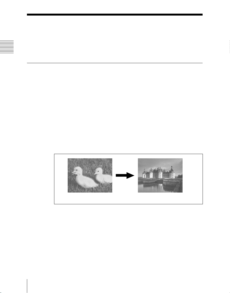
Changing the background
A background transition switches from the video currently selected on the
background A bus (the current video) to the video selected on the background
B bus (the new video).
Basic Video Processing
18
Transition
Background BBackground A
In the default selection of flip-flop mode (see page 128), the background
always switches in the direction from the A bus to the B bus. When the
transition completes, the cross-point selections on the A and B buses are
interchanged.
Page 19
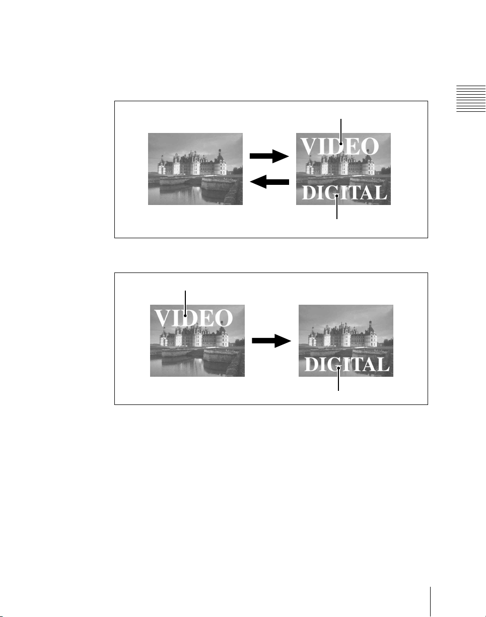
Inserting and deleting a key
You can insert one or more of the four keys (downstream keys on the PGM/
PST bank).
If you select a key which is already inserted, the transition will delete the key.
A simultaneous combination of deleting and inserting keys is also possible.
Key 1
Insert
Delete
Inserting or deleting key 1 and key 2
Transition
Key 1
Key 2
Key 2
Chapter 1 MVS-6000 Functions
Deleting key 1 and inserting key 2
19Basic Video Processing
Page 20
Chapter 1 MVS-6000 Functions
Simultaneously changing the background and keys
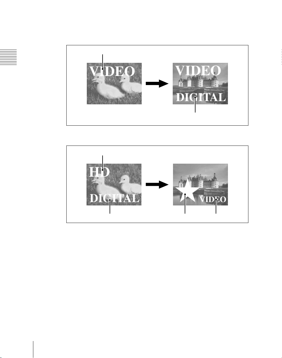
You can change any of the four keys (downstream keys on the PGM/PST bank)
and the background at the same time.
Key 1
Transition
Key 2
Changing the background and key 2 simultaneously
Key 1
Basic Video Processing
20
Transition
Key 2
Changing the background and keys 1 to 4 simultaneously
Key 3
Key 4
Selecting the transition type determines the way in which the transition occurs.
The following are the transition type.
•Mix
• NAM (non-additive mix)
• Super mix
• Preset color mix (color matte)
•Wipe
•DME wipe
• Clip transition
•Cut
Page 21

There are two modes for carrying out a transition: auto transitions are carried
out by a button operation, and manual transitions are carried out using the fader
lever. It is also possible to combine these two modes.
Independent Key Transitions
In addition to common transitions, it is possible to carry out independent
transitions on the keyers of the M/E banks and PGM/PST bank. These are
called “independent key transitions.”
By carrying out an independent key transition in combination with a common
transition, different transition types can be used for the background and keys.
The following description compares the independent key transition with a
common transition, taking a simultaneous change of the background and key
as an example.
Video used in the transition
Chapter 1 MVS-6000 Functions
Background A
Background B
Key to insert
Effect of a common transition
In the case shown in the previous illustration, carrying out a common transition
produces the following change in the image.
Transition type: wipe
Effect of a common transition
Same wipe is applied to
background and key.
21Basic Video Processing
Page 22
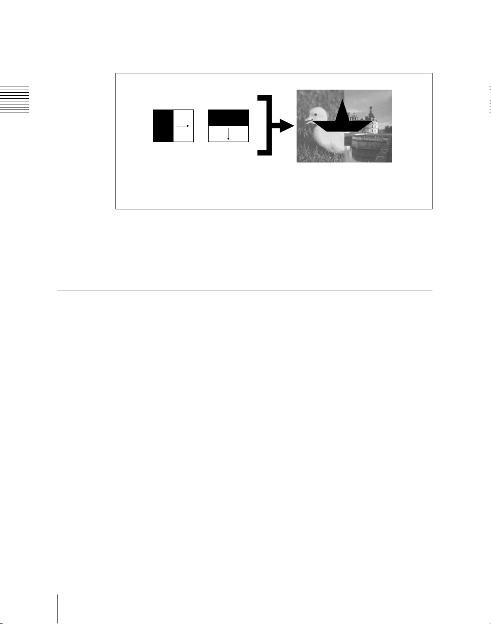
Chapter 1 MVS-6000 Functions
Effect of use with an independent key transition
The key is inserted with an independent key transition as the background
changes with a common transition, providing the following result.
Keys
Transition type:
wipe
Effect of a background transition and independent key transition
Independent key
transition type:
wipe
Different wipe patterns are applied to
the background and key transitions.
For details of transitions, see Chapter 3 “Signal Selection and Transitions”
(page 93).
A key is an effect in which a part of the background image is replaced by an
image or superimposed text. The signal determining how the background is cut
out is termed “key source,” and the signal that replaces the cut-out part is
termed “key fill.” The system component responsible for processing a key is
referred to as a keyer.
Each switcher bank has four keyers.
On each switcher bank, you can use the following key types (methods of
processing the key source).
• Luminance key
• Linear key
• Color vector key
• Chroma key
• Key wipe pattern key
Key modifiers
Basic Video Processing
22
You can apply borders and other modifiers to the edge of the key image.
Page 23

Masks
A mask allows a part of the image to be replaced by the background or a key.
To prevent unwanted holes in the background, or if a key is not the desired
shape, you can correct this with a mask.
Resizer
Wipes
This function allows you to apply effects, similar to a DME, such as zoom,
movement, or aspect ratio change to a part of a created key. You can use the
following operations.
• Two-dimensional transform of a key
• Resizer interpolation settings
• Resizer crop/border settings
• Resizer effect settings (mosaic, defocus)
For details, see Chapter 4 “Keys” (page 139).
A wipe is a transition from the current video stream to a new video stream,
using a wipe pattern.
Changing the background by means of a wipe is referred to as a “background
wipe,” and inserting or deleting a key with a wipe is termed a “key wipe.”
There are two types of wipe: those that can be selected in a common transition,
and those that can be selected in an independent key transition.
You can also specify the wipe direction, or set the pattern position, applying
various changes and modifiers to the selected wipe pattern.
For details, see Chapter 5 “Wipes” (page 199).
Chapter 1 MVS-6000 Functions
DME Wipes
A DME wipe is a wipe transition that uses a DME effect to change from one
video image to the next.
There are two types of DME wipe: those which can be selected for a normal
transition, and those which can be selected for an independent key transition.
The patterns that can be used for a DME wipe are as follows.
Slide, Squeeze, Door, Flip tumble, Frame in-out, Picture-in-picture, 2D
trans, 3D trans, Mosaic, Defocus, Brick, and User programmable DME
23Basic Video Processing
Page 24

You can also specify the wipe direction, or set the pattern position, applying
various changes and modifiers to the selected DME wipe pattern.
Resizer DME wipes
Using the resizer, you can carry out key DME wipes.
Chapter 1 MVS-6000 Functions
For details, see Chapter 6 “DME Wipes” (page 221).
Frame Memory
Frame memory is a function for using a still image or video (frame memory
clip) as material for editing.
You can create a still image by capturing a frame of input video or a clip by
specifying a range of input video. The created images and clips can be written
to memory for playback, editing, and output.
For details, see Chapter 7 “Frame Memory” (page 255).
Color Backgrounds
This function can be used to obtain color background video.
One color signal generated from the dedicated generators can be output.
For details, see “Color Background” (page 308).
Copy and Swap
Basic Video Processing
24
This function can be used to copy and swap the settings among the M/E-1 to
M/E-3, and PGM/PST banks or between keyers.
The following settings can be copied or swapped.
• Overall settings for the M/E and PGM/PST banks
• Keyer settings
• Wipe settings in a transition control block
• Wipe settings in an independent key transition control block
• DME wipe settings in a transition control block
• DME wipe settings in an independent key transition control block
• Matte data (color 1, color 2, and how to compose them)
• Color settings
• DME channel settings
• Format converter input settings (copy only)
• Format converter output settings (copy only)
Page 25

For details, see “Copy and Swap” (page 312).
Video Process
The term “video process” is applied to adjustments to the gain, hue, black level
of the input video signal. There are two types of adjustment; adjustment of an
individual primary input signal and adjustment as image effects on a particular
bus
For details, see “Video Process” (page 327).
Color Corrector
The color corrector enables video signal color correction (black balance/white
balance adjustment, gamma correction, knee correction, etc.).
The color corrector includes the following adjustments.
• Input video processing
• Primary color correction
• Secondary color correction
• RGB clip
• Luminance processing
• Spot color adjustment
• Output video processing
• YUV clip
For details, see Chapter 9 “Color Corrector” (page 331).
Chapter 1 MVS-6000 Functions
Side Flags
The term “side flags” refers to the areas to left and right of an image with aspect
ratio 4:3 embedded within a 16:9 frame, when these areas are filled with a
separate image selected from the utility bus.
25Basic Video Processing
Page 26
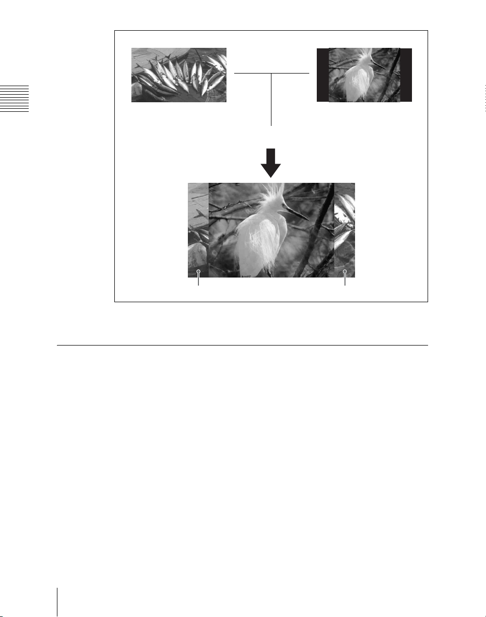
Chapter 1 MVS-6000 Functions
areas (selected from utility
bus)
Input source with aspect ratioImage to fill the side flag
Turn the side flag
function on
Side flag area
For details, see “Side Flags” (page 352).
Simple P/P Software
By installing the BZS-6250 Simple P/P Software in the MVS-6000 Switcher
Processor, you can use a separate program/preset function without using the M/
E hardware.
For details, see “Simple P/P Software” (page 357).
Side flag area
Basic Video Processing
26
Page 27

Creation of Special Effects and Management of Data and Operations
This section introduces functions used for creation of special effects, control of
external devices or switcher operations, and data management.
Digital Multi Effects (DME)
When used with the switcher, DME allows you to add three-dimensional
effects such as image movement, rotation, magnification and shrinking, as well
as a wide variety of special effects.
Each channel can be used on its own or in combination with other channels,
which allows you to create advanced effects with more complexity.
The following types of DME special effects are available.
• Edge effects: Border, Crop, Beveled Edge, Key Border, Art Edge, Flex
Shadow, Drop Shadow
• Effects for entire image: Defocus, Blur, Multi Move
• Effects for video image: Sepia, Mono, Posterization, Solarization, Nega,
Contrast, Mosaic, Mask, Sketch, Metal, Dim and Fade, Glow
• Freeze effects
• Nonlinear effects: Wave, Mosaic Glass, Flag, Twist, Ripple, Rings, Broken
Glass, Flying Bar, Blind, Split, Split Slide, Mirror, Multi Mirror,
Kaleidoscope, Lens, Circle, Panorama, Page Turn, Roll, Cylinder, Sphere,
Explosion, Swirl, Melt, Character Trail
• Lighting effects: Lighting, Spotlighting
• Recursive effects: Trail, Motion Decay, Keyframe Strobe
• Background color
• Separate Sides (effects for front and back sides)
• Signal inversion (Invert effect)
• Key density adjustment
• Key source selection
Chapter 1 MVS-6000 Functions
Global effects
Global effects are special effects created by combining the images of
successive channels. The following types of global effects are available.
• Combiner
•Brick
• Shadow
For details, see Chapter 11 “DME” (Volume 2).
27Creation of Special Effects and Management of Data and Operations
Page 28

Chapter 1 MVS-6000 Functions
External Devices
In this system, you can operate while controlling the following types of
external device:
• Devices supporting P-Bus (Peripheral II protocol)
• Devices supporting GPI
•VTRs
• Disk recorder (Sony disk 9-pin protocol and video disk communications
protocol)
• Extended VTR (Abekas A53 protocol)
For details on the devices that can be connected, consult your Sony
representative.
You can control an external device by previously registering timeline
keyframes.
For details, see Chapter 12 “External Devices” (Volume 2).
Keyframes
A keyframe represents an instantaneous state of an image; it can be saved in a
register (see “Register” in Chapter 13 (Volume 2)) and recalled for reuse.
By arranging a number of keyframes on the time axis, and interpolating
between successive keyframes, you can create an effect in which there is a
continuous change from each keyframe to the next.
Creation of Special Effects and Management of Data and Operations
28
Page 29

The following figure shows three keyframes created with a wipe pattern (the
circle) in different positions. This is interpolated to create the effect shown.
Background A
Background B
Keyframe 1 Keyframe 2 Keyframe 3
Example of keyframes and effect execution
Interpolated images
Effect execution
You can save the sequence of keyframes representing a single effect in a
register. Then by recalling this register, you can replay the same effect.
For details, see Chapter 13 “Keyframe Effects” (Volume 2).
Chapter 1 MVS-6000 Functions
Snapshots
The term “snapshot” refers to a function whereby the various settings required
to apply a particular effect to an image are saved in a register as a set of data,
for recall as required, to recover the original state.
Snapshots are divided as follows.
• Snapshots applying to a particular region (functional block of the switcher or
• Master snapshot
• Key snapshot
• Wipe snapshot
• DME wipe snapshot:
An individual snapshot may also have attached special conditions relating to
switcher or DME operation when the snapshot is recalled.
DME)
29Creation of Special Effects and Management of Data and Operations
Page 30

These conditions are called “attributes” of the snapshot, and can be added when
the snapshot is saved or recalled.
For details, see Chapter 14 “Snapshots” (Volume 2).
Chapter 1 MVS-6000 Functions
Utility
The utility function refers to a function whereby you can assign an arbitrary
action or a shortcut for frequently used menu to a particular button, then
instantly recall the action or menu by pressing the button.
For details, see “Utility Execution” in Chapter 15 (Volume 2).
Shotbox
The term “shotbox” refers to a function whereby for each specified region (see
“Region” in Chapter 13 (Volume 2)) any snapshot or keyframe effect can be
recalled simultaneously.
For details, see “Shotbox” in Chapter 15 (Volume 2).
Macros
The term “macro” refers to the function whereby a sequence of signal
selections and other operations on the control panel is saved as data in memory,
so that it can be recalled as required to automatically execute the same
sequence of operations.
The individual control panel operations constituting a macro are termed
“events.
Macros also provide the following functions.
Menu macros
The term “menu macro” refers to the function whereby a sequence of menu
operations is saved as data in memory, so that it can be recalled as required to
automatically execute the same sequence of operations.
Macro timeline
By recording macro recall and execute action on a timeline, in the same way as
for keyframes in an effect, you can automatically execute them in a sequence.
Creation of Special Effects and Management of Data and Operations
30
Page 31

Files
Macro attachment
Macro attachment is a function whereby a macro register is assigned to a
control panel button or a particular position of a fader lever, linking the
execution of the button function or a fader lever operation with a macro
execution.
For details, see Chapter 18 “Macros” (Volume 2).
Chapter 1 MVS-6000 Functions
You can save register data, including setup information and snapshot
information, as a file on a hard disk or memory card, and recall it as required.
You can operate on individual files or registers, or together in a batch.
Regarding frame memory, it is possible to capture image data stored in an
external device into frame memory. You can also convert the format of image
data in frame memory into a different format and save it in an external device.
The following files can be saved and recalled.
• Operation mode setup data for system as a whole and individual devices
• Device status data for system startup
• Key memory setting data
• Video process memory setting data
• Keyframe effect setting data
• Snapshot setting data
• Wipe snapshot setting data
• DME wipe snapshot setting data
• Key snapshot setting data
• Shotbox setting data
• Macro setting data
• Macro attachment data
• Menu macro setting data
• Frame memory image data
For details, see Chapter 17 “Files” (Volume 2).
31Creation of Special Effects and Management of Data and Operations
Page 32

Chapter 1 MVS-6000 Functions
Setup
Various settings are required, in order to operate the switcher, control panel,
DME, external devices, and so on, connected together in a single system.
This is referred to as “setup,” and you can carry out the setup operations from
the Engineering Setup menu.
The settings in the Engineering Setup menu are grouped under the following
headings.
• System setup (System)
For details, see Chapter 18 “System Setup” (Volume 3).
• Panel setup (Panel)
For details, see Chapter 19 “Control Panel Setup (Panel)” (Volume 3).
• Switcher setup (Switcher)
For details, see Chapter 20 “Switcher Setup (Switcher)” (Volume 3).
• DME setup (DME)
For details, see Chapter 21 “DME Setup (DME)” (Volume 3).
• DCU setup (DCU)
32
For details, see Chapter 22 “DCU Setup (DCU)” (Volume 3).
• Router/tally setup (Router/Tally)
For details, see Chapter 23 “Setup Relating to Router Interface and Tally
(Router/Tally)” (Volume 3).
Setup
Page 33

Chapter 2 Menus and Control Panel
Names and Functions of Parts of the Control Panel ...............................34
Example Control Panel Configuration ................................................34
Cross-Point Control Block ..................................................................36
Transition Control Block .....................................................................37
Device Control Block (Joystick) .........................................................42
Keyframe Control Block .....................................................................43
Numeric Keypad Control Block ..........................................................46
Auxiliary Bus Control Block ...............................................................49
Menu Control Block ............................................................................50
Memory Card/USB Adaptor Block .....................................................51
“Memory Stick”/USB Connections Block ..........................................52
Key Control Block (MKS-8035 Key Control Module, Option) .........54
Device Control Block (MKS-8031TB Trackball Module, Option) ....58
Device Control Block (MKS-8036A Search Dial Module, Option) ...61
Utility/Shotbox Control Block (MKS-8033 Utility/Shotbox Module,
Option) .....................................................................................65
Downstream Key Control Block (MKS-8032 DSK Fader Module,
Option) .....................................................................................66
Basic Menu Operations ..............................................................................68
Menu Organization ..............................................................................68
About the Top Menu List ....................................................................68
Accessing Menus .................................................................................68
Displaying a Menu ..............................................................................74
Interpreting the Menu Screen ..............................................................75
Menu Operations .................................................................................77
Switching Between the Main Menu Site and Subsidiary Menu Site ..89
Shortcut Menu .....................................................................................89
Page 34
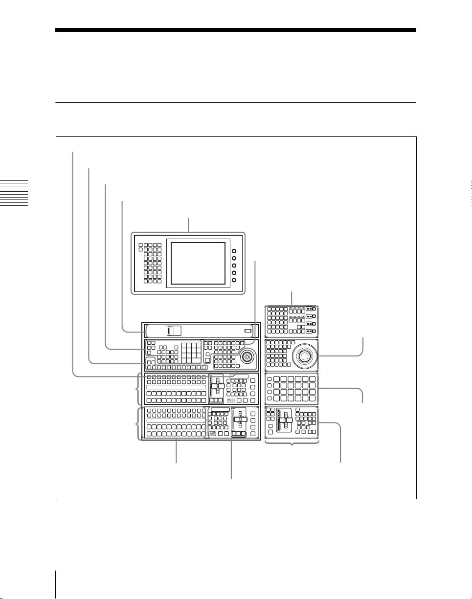
Names and Functions of Parts of the Control Panel
Example Control Panel Configuration
Device control block (joystick) (page 42)
Auxiliary bus control block (page 49)
Numeric keypad control block (page 46)
“Memory Stick”/USB connections block (page 52)
Chapter 2 Menus and Control Panel
Menu control block (page 50)
Keyframe control block (page 43)
Key control block (page 54)
Device control block
(page 58)
M/E-1 bank
PGM/PST bank
Cross-point control block (page 36)
Example control panel configuration (with CCP-9000A 2M/E panel)
Names and Functions of Parts of the Control Panel
34
Up to three units
connectable
Transition control block (page 37)
Utility/Shotbox control
block (page 65)
Downstream key control
block (page 66)
Page 35
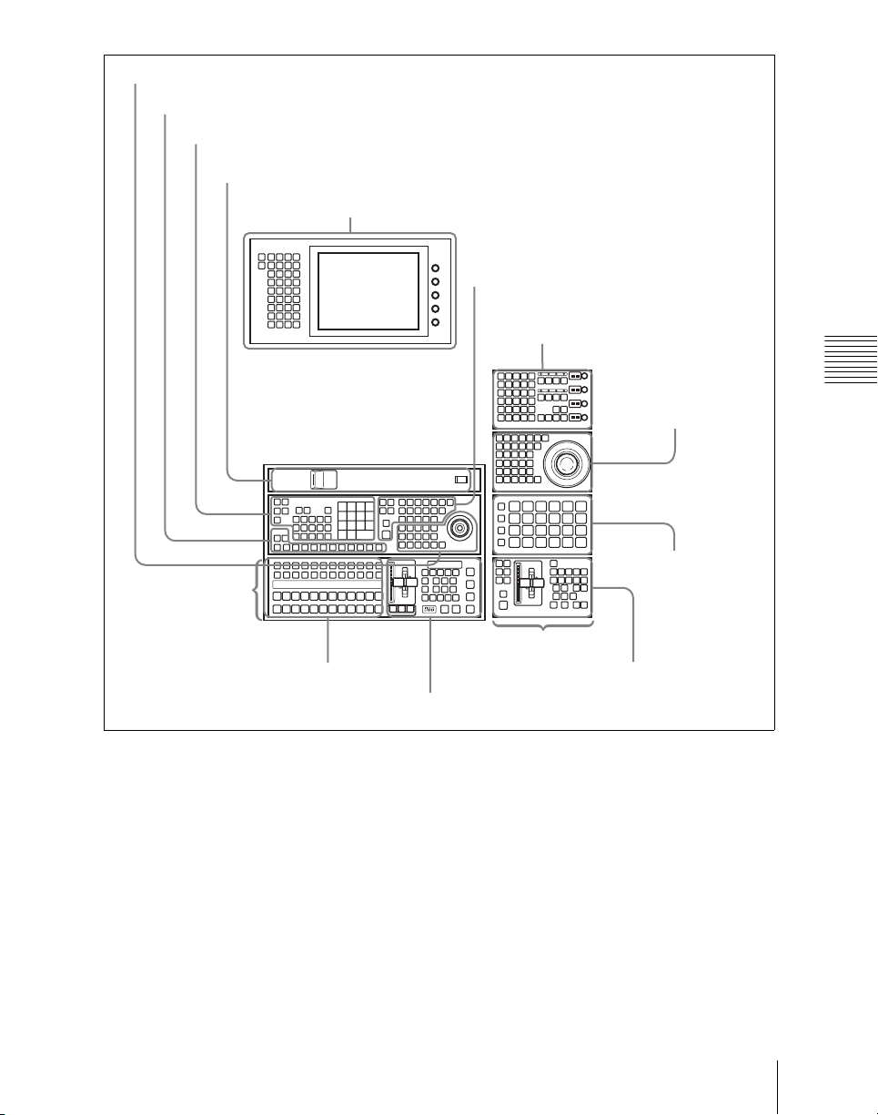
Device control block (joystick) (page 42)
Auxiliary bus control block (page 49)
Numeric keypad control block (page 46)
“Memory Stick”/USB connections block (page 52)
Menu control block (page 50)
M/E-1 bank
Keyframe control block (page 43)
Key control block (page 54)
Chapter 2 Menus and Control Panel
Device control block
(page 58)
Utility/Shotbox control
block (page 65)
Cross-point control block (page 36)
Transition control block (page 37)
Example control panel configuration (with CCP-9000A 1M/E panel)
Up to three units
connectable
Downstream key control
block (page 66)
35Names and Functions of Parts of the Control Panel
Page 36
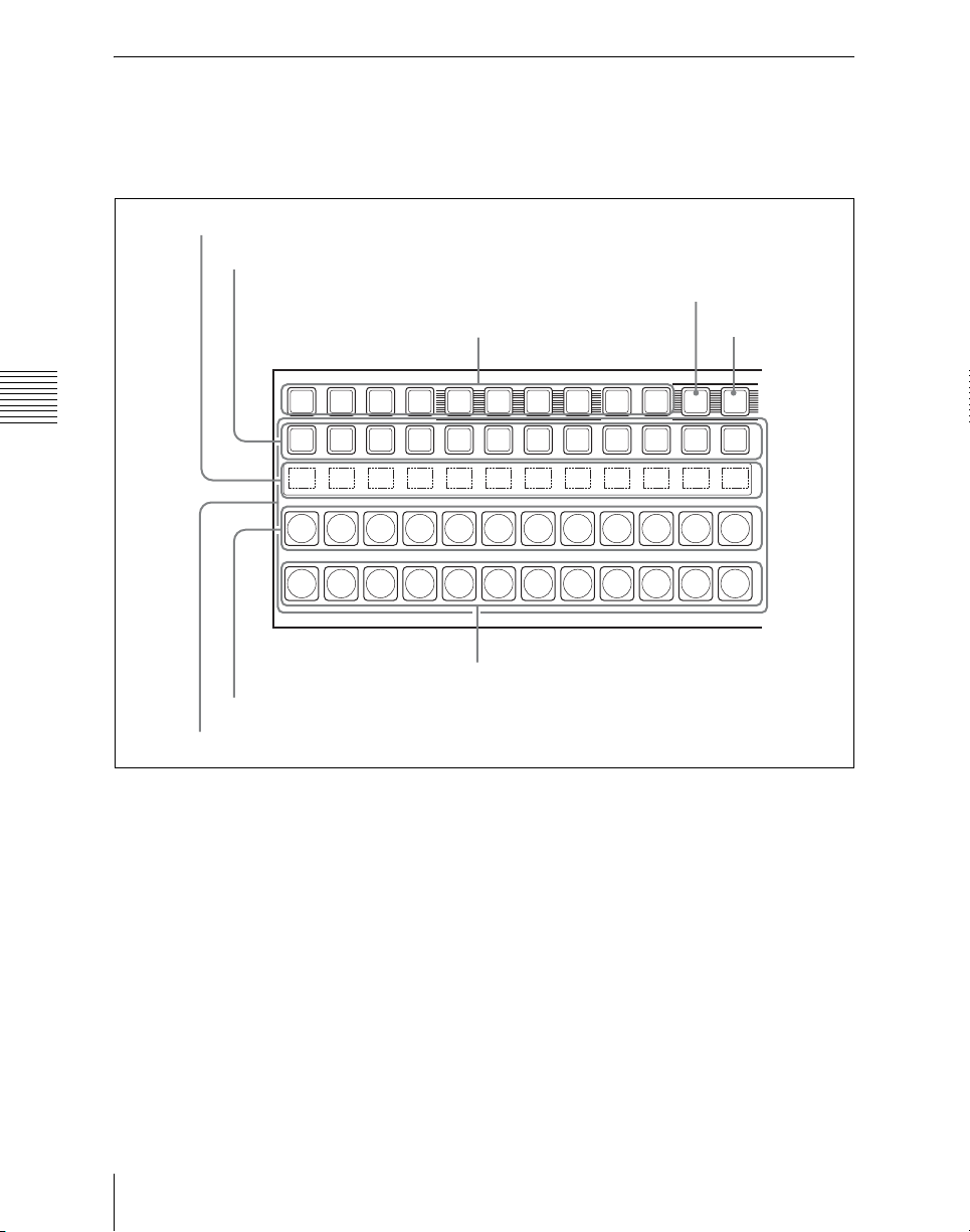
Cross-Point Control Block
In the cross-point control block, you can
select the signals to be used in this M/E
bank or PGM/PST bank.
2 Source name displays
Key row
4 XPT HOLD button
Key row delegation buttons
Chapter 2 Menus and Control Panel
5 SHIFT button
XPT
SHIFTUTILDME2DME1DSK4DSK3DSK2DSK1
HOLD
Background A row
1 Cross-point buttons
a Cross-point buttons
These buttons select the signals used for
video creation on this M/E bank or PGM/
PST bank. Each row of buttons corresponds
to one or more signal buses within the
switcher.
Key row: The buttons in this row select the
bus signals specified with the key row
delegation buttons ([DSK1] to [DSK4],
[DME1] to [DME2] or [UTIL]) or
delegation buttons in the auxiliary bus
control block.
Names and Functions of Parts of the Control Panel
36
Background B row
The later pressed delegation button
takes precedence and the selection is
reflected in the key row.
Background A row: Press the desired
button to select the signal as the current
background video on this M/E bank or
PGM/PST bank.
Background B row: Press the desired
button to select the signal as the
background after the next transition on
this M/E bank or PGM/PST bank.
Page 37

Cross-point button numbers
Cross-point button and reentry buttons are
respectively numbered.
c Key row delegation buttons
Use these buttons to assign buses to the key
row, copy keys, or assign DME to keys.
For details, see “Cross-point button
control block button numbers” (page 99).
Assigning signals to button
You can assign a signal to each button using
the Setup menu.
For details on the operation, see “CrossPoint Settings (Xpt Assign Menu)” in
Chapter 19 (Volume 3).
Visual indications on cross-point
buttons
For details on the operation, see “Colors of
lit cross-point buttons” (page 102).
b Source name displays
These show the names of the signals which
can be selected on the cross-point buttons,
in two or four characters, or in auto mode.
While the [SHIFT] button or the [SHIFT]
button assigned to the column of crosspoint buttons is enabled, the source name of
the signal assigned to the column of crosspoint buttons in shift mode appears. You
can select green, orange, or yellow for the
background color of the source name
display, for each source separately. You can
set the source name display mode and
background color in a Setup menu.
d XPT (cross-point) HOLD button
Turning this button on enables you to recall
a keyframe or snapshot while keeping the
current cross-point selection unchanged.
This function is valid for the background A
and B rows.
By means of setup settings, you can also
enable this for the following function
blocks.
• Background A and B rows
•Key buses
• Utility
• External DME bus
e SHIFT button
When this button is enabled, either the
source name displays show the shifted
signal names, or the shifted signals for all
buses in this M/E (P/P) bank are enabled.
You can select either mode in a Setup
menu.
Each press of the button toggles between
the enabled and disabled states.
Using a Setup menu operation, you can also
make this button function as the [SHIFT]
button for the whole cross-point control
block inclusive of the key row and
background A and B rows.
Chapter 2 Menus and Control Panel
Transition Control Block
In the transition control block, you can
modify the output of the M/E bank or PGM/
PST bank, and perform transitions. Both
common transition and independent key
transition operations are possible.
37Names and Functions of Parts of the Control Panel
Page 38
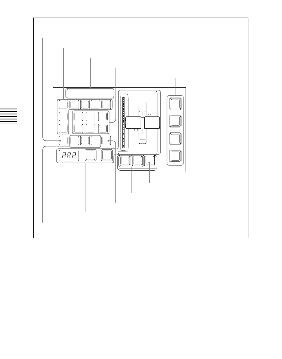
9 PRIOR SET button
1 Next transition selection buttons
8 Key status display
2 Transition type selection buttons
0 Independent key/downstream
key transition execution section
ON
1 2 3 4ON1 2 3 4ON1 2 3 4
BKGD KEY1 KEY2 KEY3 KEY4
KEY
MIX
PRIOR
Chapter 2 Menus and Control Panel
ALL
PRIOR
SET
NORM
PST
COLOR
MIX
NORM
/REV
NAM
WIPE
AUTO
TRANS
ON
1 2 3 4
DSK1
TRANS
SUPER
MIX
DME
TRANS
REV
PVW
CUT
PTN
LIMIT
LIMIT
KF
SET
DSK2
TRANS
DSK3
TRANS
DSK4
TRANS
7 KF button
6 Pattern limit buttons
5 TRANS PVW button
3 Transition execution section
4 Wipe direction selection buttons
a Next transition selection buttons
Press these buttons, turning them on, to
determine what the next transition will
apply to.
BKGD: Next transition changes the
background.
KEY1 to KEY4 (DSK1 to DSK4 in the
PGM/PST bank): Press this button,
turning it on, to make the next
key is currently inserted it will be
removed, and vice versa.
In the PGM/PST bank, this inserts or
removes downstream keys 1 to 4.
KEY PRIOR (priority): When this button
is lit, the setting of the key priority after
the next transition is enabled. The key
priority after the next transition appears
in the key status display.
transition insert or remove the
corresponding key (keys 1 to 4). If a
Names and Functions of Parts of the Control Panel
38
Page 39

ALL: Pressing this button turns on a
preselected set of the [BKGD], [KEY1]
to [KEY4], and [KEY PRIOR] buttons.
Make this setting in a Setup menu.
b Transition type selection buttons
You can assign these buttons in setup to any
transition type (see “Overall Control Panel
Settings (Config Menu)” in Chapter 19
(Volume 3)).
Press one of these buttons, turning it on, to
determine the type of the next transition.
When multi-program mode is selected in
the Setup menu (see “Settings for Switcher
Configuration (Config Menu)” in Chapter
20 (Volume 3)), two or more of the
following buttons may light.
You can also assign a function to these
buttons to select whether or not the fader
levers are used as keyframe faders.
MIX: In a background transition, the new
video fades in as the current video
fades out. During the transition, the
overall signal level is maintained at
100%.
In a key transition, the key fades in (for
insertion) or out (for removal).
NAM (non-additive mix): The current and
new video signals are compared, and
the signal with the higher luminance
level is given priority in the output.
The current video is maintained at
100% output for the first half of the
transition as the new video increases
progressively to 100%, then the current
video is progressively reduced from
100% to zero in the second half while
the new video is maintained at 100%.
SUPER MIX: The current video is
maintained at 100% output for the first
half of the transition as the new video is
mixed while increasing progressively
to 100%. The current video is then
progressively reduced from 100% to
zero in the second half while the new
video is maintained at 100%.
PST (preset) COLOR MIX: In the first
transition, the current video is replaced
by the color matte in a mix (dissolve),
then in the second transition the color
matte is replaced by the new video also
in a mix (dissolve).
In place of a color matte, you can select
any signal on the utility bus.
WIPE: The current video is replaced by the
new video, using the wipe pattern
selected in the Wipe menu.
DME: A wipe type of transition is carried
out, using the DME effect selected in
the DME Wipe menu.
FM1&2CLIP, FM3&4CLIP,
FM5&6CLIP, FM7&8CLIP: A
recorded clip is played back together
with the transition. At this point, you
can also carry out a transition (wipe or
mix (dissolve)) simultaneously
together with the clip.
KF (keyframe): Press this button, turning
it on, to enable using the fader lever as
a keyframe fader.
c Transition execution section
Transition indicator: This comprises
multiple LEDs, which show the
progress of the transition.
Fader lever: Move up or down to carry out
the transition. When the [KF] button or
a transition type selection button to
which the KF button function has been
assigned is lit, you can use this as a
keyframe fader.
Transition rate display: This shows the
“transition rate” (the time from the
beginning of a transition to its
completion) set for an auto transition,
in frames.
You can set the transition rate using the
numeric keypad control block or menu.
AUTO TRANS (transition) button:
Pressing this button carries out an auto
transition of the set transition rate
(duration). The transition starts
Chapter 2 Menus and Control Panel
39Names and Functions of Parts of the Control Panel
Page 40

immediately, and the button lights
amber. When the transition completes,
the button goes off.
CUT button: Pressing this button carries
out the transition as a cut (i.e.
instantaneously).
During the preview, you can use the fader
lever, [AUTO TRANS] button, and [CUT]
button. One of the following functions of
this button can be selected in a Setup mode.
• When the transition completes, the
system returns to the normal mode.
• The transition preview mode is
d Wipe direction selection buttons
When you have selected a wipe or DME
wipe as the transition type, press one of
these buttons, turning it on, to select the
maintained while this button is pressed.
• Switching is made between the transition
preview mode and normal mode every
time this button is pressed.
wipe direction.
NORM (normal): The wipe proceeds in
the direction from black to white as
shown on the pattern in the lists of
Chapter 2 Menus and Control Panel
patterns see “Wipe Pattern List” (page
362) and “DME Wipe Pattern List”
(page 363), or in the direction of the
arrow.
When the VTR/disk recorder/frame
memory operation mode is enabled in
setup, pressing this button plays the
tape.
REV (reverse): The wipe proceeds in the
opposite direction to that when the
[NORM] button is pressed.
When the VTR/disk recorder/frame
memory operation mode is enabled in
setup, pressing this button cues the tape
automatically to the start point.
NORM/REV (normal/reverse): The wipe
direction alternates between normal
and reverse every time a transition is
executed.
When the VTR/disk recorder/frame
memory operation mode is enabled in
setup, pressing this button stops the
tape.
e TRANS PVW (transition preview)
button
When this button is lit, you can check in
advance the video changes during the
transition, on the preview output from the
M/E or PGM/PST bank.
f Pattern limit buttons
PTN (pattern) LIMIT: Pressing this
button, turning it on, enables the
pattern limit function.
When the VTR/disk recorder/frame
memory operation mode is enabled in
setup, pressing this button plays the
tape.
LIMIT SET: Use this button to set a
pattern limit when the [PTN LIMIT]
button is off.
Move the fader lever to the position of
a particular pattern size, and stop it
there, then press this button to set the
pattern limit range.
When the VTR/disk recorder/frame
memory operation mode is enabled in
setup, pressing this button stops the
tape.
g KF (keyframe) button
When the VTR/disk recorder/frame
memory operation mode is enabled in
setup, pressing this button cues the tape
automatically to the start point. When not,
pressing this button to turn it on allows you
to use the fader lever as a keyframe fader.
h Key status display
For each of keys 1 to 4, the corresponding
ON indicator lights when the key is
inserted. It also shows the priority (1 to 4)
of each key.
Names and Functions of Parts of the Control Panel
40
Page 41

i PRIOR (priority) SET button
While this button is held down, you can set
the key priority.
The setting mode when this button is
pressed depends on whether or not the
[KEY PRIOR] button is lit, as follows.
• When the [KEY PRIOR] button is off, the
current key priority is set.
• When the [KEY PRIOR] button is lit, the
key priority after the next transition is set.
Press the [KEY PRIOR] button as required,
to switch between these two modes.
In either mode, hold down the [PRIOR
SET] button, and press the button ([KEY1]
to [KEY4]) corresponding to the key you
want to bring to the front.
The following controls are used as the
independent key transition control block.
j Independent key/downstream key
transition execution section
KEY1 TRANS to KEY4 TRANS (DSK1
TRANS to DSK4 TRANS in the
PGM/PST bank) buttons: These
correspond to keys 1 to 4 from top to
bottom; press one to carry out an auto
transition. The transition rate for an
independent key transition can be set in
the numeric keypad control block or in
a menu.
The color with which buttons are lit shows
the status, as follows.
Lit green: During a transition
Lit amber: Key on. Not inserted into
program video (final output video from
the switcher).
Lit red: Key on. Inserted into program
video (final output video from the
switcher).
Not lit: Key off.
Chapter 2 Menus and Control Panel
41Names and Functions of Parts of the Control Panel
Page 42
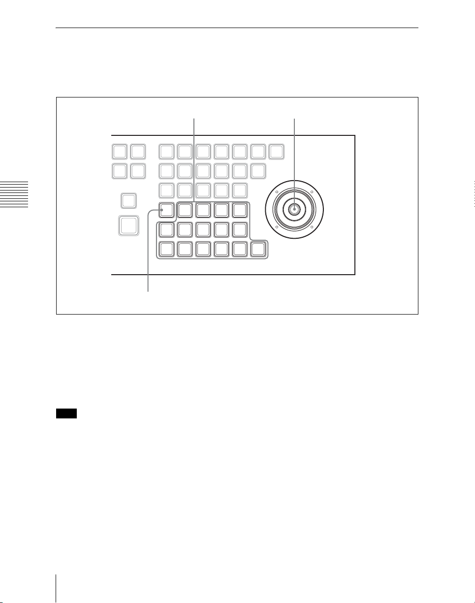
Device Control Block (Joystick)
The joystick type device control block is
used for three-dimensional transform
operations using a DME.
1 Operating buttons 2 Joystick
STOP
EFF
LOOP
NORM
/REV
RE
Chapter 2 Menus and Control Panel
WIND
RUN
EDIT
NEXT
ENBL
KF
COPY
INS
MENU
AXIS
LOC
SHIFT
EFF
KF
DUR
DUR
PASTEREV
DEL
GOTO
MOD
KF/TC
LOCAL GLB SRC TRGT
ASP
LOC
SKEW
SIZE
PERS
CLR
X
WORK
BUFR
3 MENU button
CONST
DELAY
DUR
FROMTORUN
UNDO
NEXT
PREV
KF
KF
LOC
ROT
XYZ
Y Z CTR
KF
PAUSE
LOOP
CTRL
a Operating buttons
The functions of these buttons are
equivalent to the functions in threedimensional transform operation mode of
the operating buttons of the trackball type
device control block.
Note
To select a required DME channel, use the
region selection buttons in the numeric
keypad control block.
Use of the SHIFT button
Pressing a button in the device control
block while holding down the [SHIFT]
button enables the shifted function of the
button. Also, pressing a button in the
keyframe control block while holding down
Names and Functions of Parts of the Control Panel
42
the [SHIFT] button enables the shifted
function of the button.
About the [CLR WORK BUFR] (clear
work buffer) button
When [M/E-1] or [P/P] is selected along in
the numeric region selection buttons of the
keypad control block, press this button
twice in rapid succession to reset all
parameters of the selected M/E or P/P to
their initial values. When a DME channel is
selected in the region selection buttons, the
operation is the same as when using a
trackball type device control block in the
three-dimensional transform operation
mode.
Page 43

b Joystick
When the three-dimensional transform
operation mode is enabled
By moving this, you can carry out
operations in the x-, y-, and z-axes.
When the following buttons are held down,
operation of the joystick is switched to a
finer control. (fine mode)
• The button on the end of the joystick
• [SRC] button
• [TRGT] button
Depending on the settings made in the
Setup menu, the operation speed multiple
can be changed.
Keyframe Control Block
In the keyframe control block, you can
carry out effect editing and execution.
When the effect run control mode is
enabled
By moving the joystick sideways, you can
run the keyframe effect, independent of the
STOP NEXT KF, EFF LOOP, and similar
settings in the keyframe control block.
Move to the right to run the effect in the
normal direction, and to the left for the
reverse direction.
c MENU button
The function of this button is equivalent to
the function of the [MENU] button in the
trackball type device control block.
Chapter 2 Menus and Control Panel
43Names and Functions of Parts of the Control Panel
Page 44
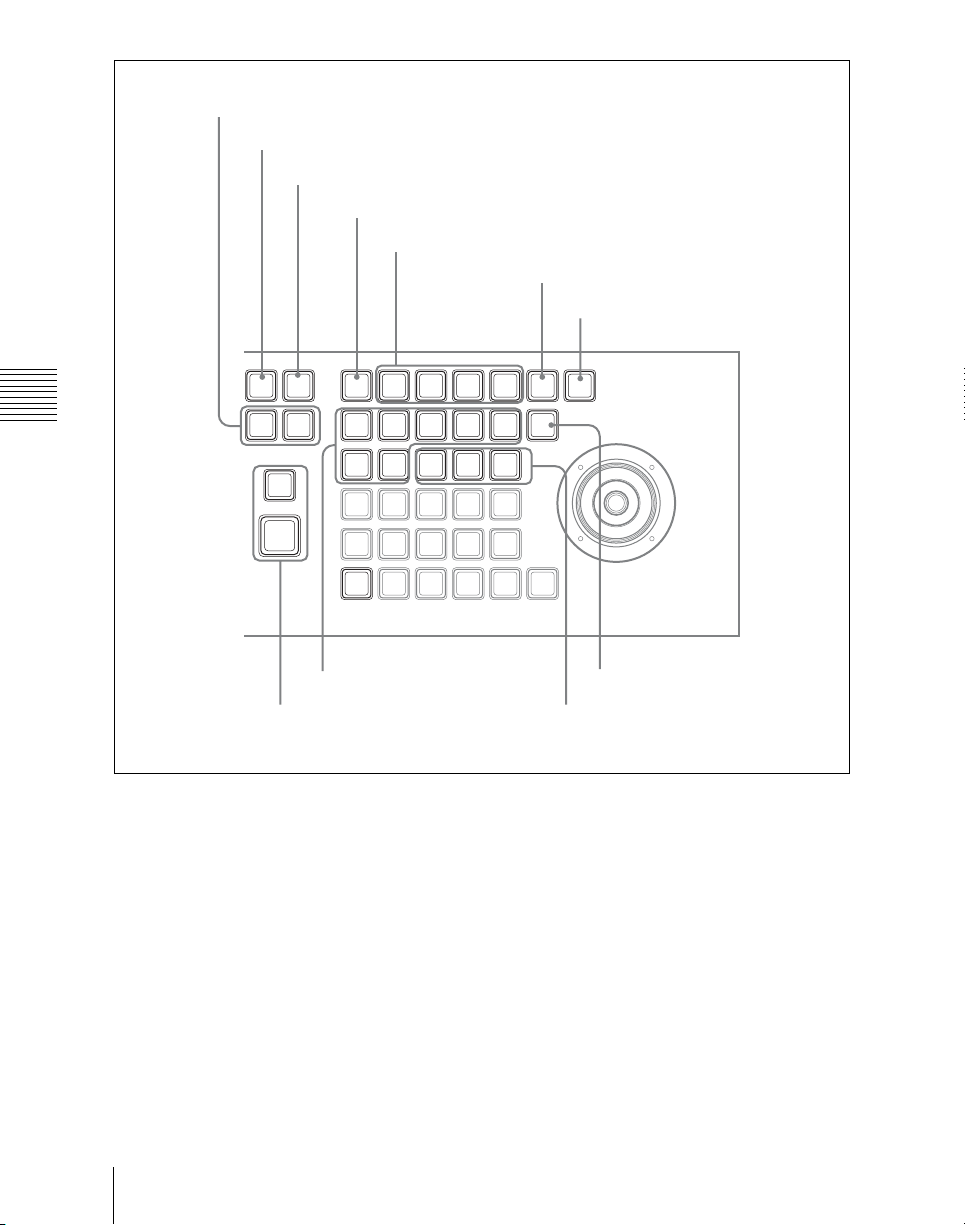
8 Effect execution direction selection buttons
0 EFF LOOP button
9 STOP NEXT KF button
1 EDIT ENBL button
4 Duration setting buttons
5 KF LOOP button
6 PAUSE button
STOP
EFF
LOOP
Chapter 2 Menus and Control Panel
NORM
/REV
RE
WIND
RUN
EDIT
NEXT
ENBL
KF
COPY
INS
MENU
AXIS
LOC
SHIFT
EFF
KF
DUR
DUR
PASTEREV
DEL
GOTO
MOD
KF/TC
LOCAL GLB SRC TRGT
ASP
LOC
SKEW
SIZE
PERS
CLR
X
WORK
BUFR
DELAY
UNDO
PREV
KF
LOC
XYZ
Y
CONST
DUR
FROMTORUN
NEXT
KF
ROT
Z CTR
KF
PAUSE
LOOP
CTRL
3 Editing buttons
7 Effect execution section
a EDIT ENBL (edit enable) button
Press this button, turning it on, to enable
effect editing operations with the keyframe
control block.
When macro editing is carried out, this
button lights red.
b Edit point specification buttons
GO TO KF/TC (Go to keyframe/
timecode): Press this button, turning it
on, to enter a numeric value from the
numeric keypad control block, and
Names and Functions of Parts of the Control Panel
44
qa RUN CTRL button
2 Edit point specification buttons
move the edit point to the specified
keyframe.
To move the edit point to the specified
timecode position, hold down the
[SHIFT] button in the device control
block, then press this button, turning it
on, and enter the desired numeric value
from the numeric keypad control block.
During macro editing, pressing this
button moves the edit point to the event
number specified by numeric entry
with the numeric keypad control block.
Page 45

PREV KF (previous keyframe): When
this button is pressed, the edit point
moves to the keyframe immediately
before the current time (the position
where the effect is currently stopped).
During macro editing, pressing this
button moves the edit point to the event
immediately before the current event.
NEXT KF (next keyframe): When this
button is pressed, the edit point moves
to the keyframe immediately after the
current time.
During macro editing, pressing this
button moves the edit point to the event
immediately after the current event.
c Editing buttons
FROM TO: Press this button, turning it on,
to enter numeric values from the
numeric keypad control block, and
select a specified range of keyframes
(during macro editing, the specified
range of events).
INS (insert): When this button is pressed, a
new keyframe is inserted after the
current keyframe. Pressing this button
while holding down the [SHIFT]
button in the device control block
inserts a new keyframe before the
current keyframe.
During macro editing, pressing this
button moves the edit point to the event
immediately after the current event.
MOD (modify): When this button is
pressed, the selected keyframe is
modified with the values of the current
keyframe. When the edit point is
between two keyframes, the
immediately preceding keyframe is
modified. You can also select multiple
keyframes, and modify them in a single
operation. At this time, pressing this
button while holding down the
[SHIFT] button in the device control
block modifies all selected keyframes
with the changed values taken as
relative values.
During macro editing, pressing this
button amends the selected event.
DEL (delete): When this button is pressed,
the selected keyframe is deleted. When
the edit point is between two
keyframes, the immediately preceding
keyframe is deleted. During macro
editing, pressing this button deletes the
selected event. You can also select
multiple keyframes or macro events,
and delete them in a single operation.
COPY: When this button is pressed, the
selected keyframe (during macro
editing, macro event) is copied. You
can also select multiple keyframes or
macro events, and copy them in a
single operation.
PASTE: When this button is pressed, the
deleted or copied keyframe (during
macro editing, macro event) is inserted
after the current keyframe (during
macro editing, macro event). Pressing
this button while holding down the
[SHIFT] button in the device control
block inserts the deleted or copied
keyframe (during macro editing, macro
event) before the current keyframe
(during macro editing, macro event).
UNDO: When this button is pressed, the
last executed keyframe (during macro
editing, macro event) insertion,
modification, or deletion, or paste
operation is canceled.
d Duration setting buttons
KF DUR (keyframe duration): Press this
button, turning it on, to set the
keyframe duration of the selected
keyframe, by numeric value entry from
the numeric keypad control block.
EFF DUR (effect duration): Press this
button, turning it on, to set the effect
duration from the numeric keypad
control block.
Chapter 2 Menus and Control Panel
45Names and Functions of Parts of the Control Panel
Page 46

DELAY: Press this button, turning it on, to
enter a delay value from the numeric
keypad control block.
CONST DUR (constant duration): Select
the duration mode. When this is lit, the
mode is constant duration mode, and
when off, variable duration mode.
e KF LOOP (keyframe loop) button
Press this button, turning it on, to execute
the effect the specified number of times
through the keyframes in the specified
range.
f PAUSE button
Chapter 2 Menus and Control Panel
When this button is pressed, a pause is
applied to the selected keyframe.
When editing a macro, press this button,
turning it on, to include a pause event in the
macro. The pause length can be set in the
numeric keypad control block.
g Effect execution section
RUN: When this button is pressed, the
effect is run from the first keyframe to
the last keyframe. However, if a pause
is set on a keyframe, the effect stops at
that point. Press this button again to
resume execution, and continue to the
next pause point or the end of the
effect.
REWIND: When this button is pressed, the
currently recalled effect is rewound to
the first keyframe.
h Effect execution direction selection
buttons
REV (reverse): When this button is off,
effect execution runs from the first
keyframe to the last keyframe. When
this button is lit, effect execution runs
from the last keyframe to the first
keyframe.
NORM/REV (normal/reverse): Press this
button, turning it on, to reverse the
direction of the effect when it reaches
the last keyframe or first keyframe.
i STOP NEXT KF (stop next
keyframe) button
When this button is pressed, turning it on,
the effect execution range is from the
current time to the next keyframe.
j EFF LOOP (effect loop) button
When the effect reaches the last keyframe
with this button on, it returns to the first
keyframe and repeats.
k RUN CTRL (run control) button
When this button is on, you can execute
keyframe effects without being affected by
the STOP NEXT KF or EFF LOOP settings
in the keyframe control block.
Numeric Keypad Control Block
The numeric keypad control block is used
for region selection, for saving and
recalling snapshots, effects and shotboxes,
for entering numeric values for trackball
operation and keyframe operation, and for
transition rate entry.
Names and Functions of Parts of the Control Panel
46
Page 47
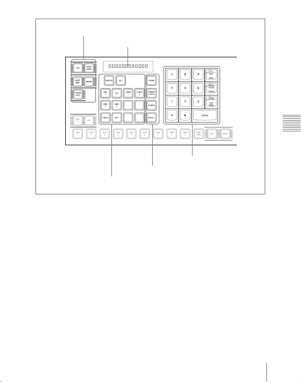
1 Mode selection buttons
5 Display
2 Region selection buttons
Chapter 2 Menus and Control Panel
4 Numeric keypad
3 Function selection buttons
a Mode selection buttons
EFF (effect): Press to save or recall an
effect.
SNAPSHOT: Press to save or recall a
snapshot.
SHOTBOX: Press to save or recall a
shotbox.
MCRO (macro): Press to save, recall or
edit a macro.
TRANS RATE (transition rate): Press to
set the transition rate.
Hold down this button, and press one of
the key row delegation buttons [KEY1]
to [KEY4] in the cross-point control
block to set an independent key
transition rate.
b Region selection buttons
These select the functional block (“region”)
of the control panel to which operations
apply.
You can select more than one region at the
same time.
The first button you press is taken as the
reference region, and lights green, while the
next pressed button lights amber.
With the exception of the [MASTER] and
[ALL] buttons, you can change the region
assignment to the buttons as desired in the
Setup menu.
MASTR: Press this, turning it on, to save
region information in a master
snapshot register or master timeline
register, or to recall such region
information.
47Names and Functions of Parts of the Control Panel
Page 48

ALL: Select all regions. When any region
is already selected, pressing this button
makes all regions unselected.
M/E 1 and P/P: Select the corresponding
regions, M/E-1 and PGM/PST.
USER 1 to USER 8: Select the
corresponding User regions.
DME1 and DME2: Select a DME channel.
P-Bus: Select the P-Bus region.
GPI: Select the GPI region.
RTR: Select the router region.
DEV1 to DEV12: Select the Device 1 to
Device 12 regions respectively.
MCRO: Select the macro region.
[SNAPSHOT] button or [SHOTBOX]
button is lit, this is used to find an
empty register.
+/–/ EFF DISS (effect dissolve): Invert the
sign, negative or positive.
When the [SNAPSHOT] button is lit,
applies the effect dissolve attribute to a
snapshot.
CLR/AUTO TRANS (clear/auto
transition): Clear an input value,
returning to the previous state.
When the [SNAPSHOT] button is lit,
applies the auto transition attribute to a
snapshot.
TRIM/GPI ENBL (enable): After
Chapter 2 Menus and Control Panel
c Function selection buttons
UNDO: After recalling a register, press this
button to return to the state before
recalling the register.
entering a difference value to be added
to an existing setting, press this button
to confirm the change.
ENTER: Confirm an entered value.
STORE STATS (store status): This lights
amber when data is stored in a register.
After saving data to a register, hold
down this button and press the
e Display
This shows the selected region name and
entered numeric values.
[UNDO] button to return the register to
the state before the data was saved.
STORE: Press this button to switch to the
mode for saving a snapshot, effect,
shotbox or macro in a register.
RCALL (recall): Press this button to
switch to the mode for recalling a
snapshot, effect, shotbox or macro
from a register.
[STORE] button or [RCALL] button
flashes amber when one or more of the
regions assigned to the Region selection
buttons are not selected by the Region
Select menu.
d Numeric keypad
In addition to the buttons for numeric input,
this includes buttons for adding attributes to
snapshots.
0 to 9: Used to input numeric digits.
. (period): Enters the decimal point.
When the [TRANS RATE] button is lit,
enters “00.” When the [EFF] button,
Names and Functions of Parts of the Control Panel
48
Page 49
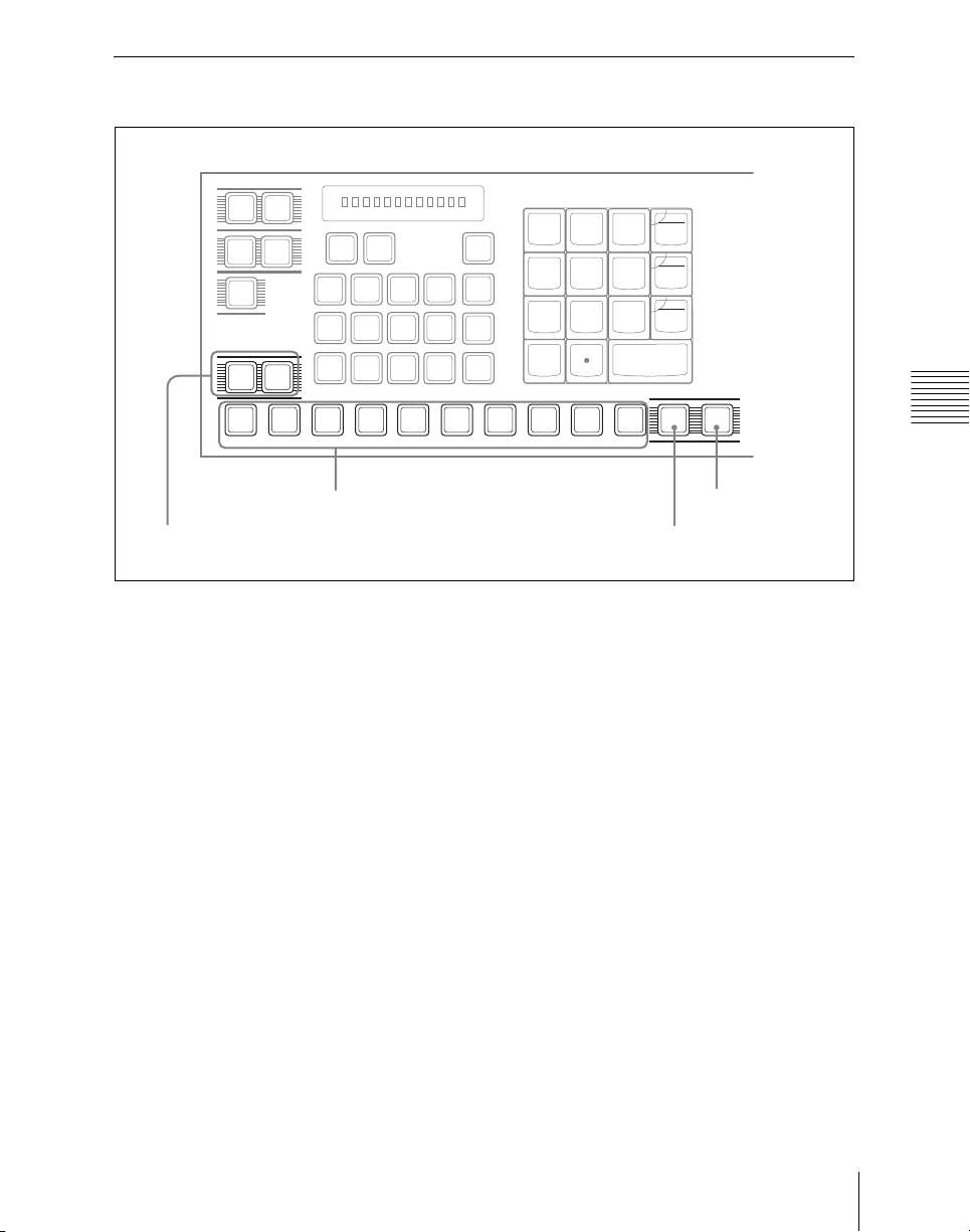
Auxiliary Bus Control Block
SNAP
EFF
SHOT
SHOT
BOX
TRANS
RATE
M/E
MCRO
1
M/E
1
DME1DME2DME3DME
P-BUS
P/P
MASTR ALL
P/P
GP1
USER1USER
STORE
2
STORE
4
UNDO
STATS
RCALL
7
4
5
2
1
0
DISS
CLR
AUTO
6
TRANS
TRIM
3
GPI
ENBL
ENTER
+/-
EFF
9
8
AUX1AUX2AUX3AUX4AUX5AUX6AUX7FMS1FMS2EDIT
1 AUX delegation buttons
2 Bank selection buttons
a AUX delegation buttons
Press one of these buttons, turning it on, to
select the bus to assign to the key row of the
bank selected with the bank selection
buttons. These 10 buttons from left to right
have ID numbers 1 to 10. When the
[SHIFT] button is enabled, their ID
numbers switch to 11 to 20. Pressing one of
the buttons selects the bus assigned to the
ID number. That is, you can select up to 20
buses using these AUX delegation buttons
in combination with the [SHIFT] button.
The assignment of buses to the ID numbers
can be done in a Setup menu.
For buses that can be selected, see “Bus
Selection” (page 97).
For each bank, the key row is shared
between the auxiliary bus control block and
cross-point control block. Priority is given
to the control block in which the delegation
KEY SHIFT
PVW
4 SHIFT button
3 KEY button
button is last pressed. When priority is
given to the cross-point control block, all
these buttons go off.
b Bank selection buttons
These select the bank for which the AUX
delegation buttons are enabled.
c KEY button
While this button is held down, you can use
the cross-point row of buttons to select key
signals.
d SHIFT button
While this button is enabled, the AUX
delegation buttons have the shifted ID
numbers. In a Setup menu, you can select
one of the following three modes for this
button.
• The button takes effect while being held
down.
Chapter 2 Menus and Control Panel
49Names and Functions of Parts of the Control Panel
Page 50
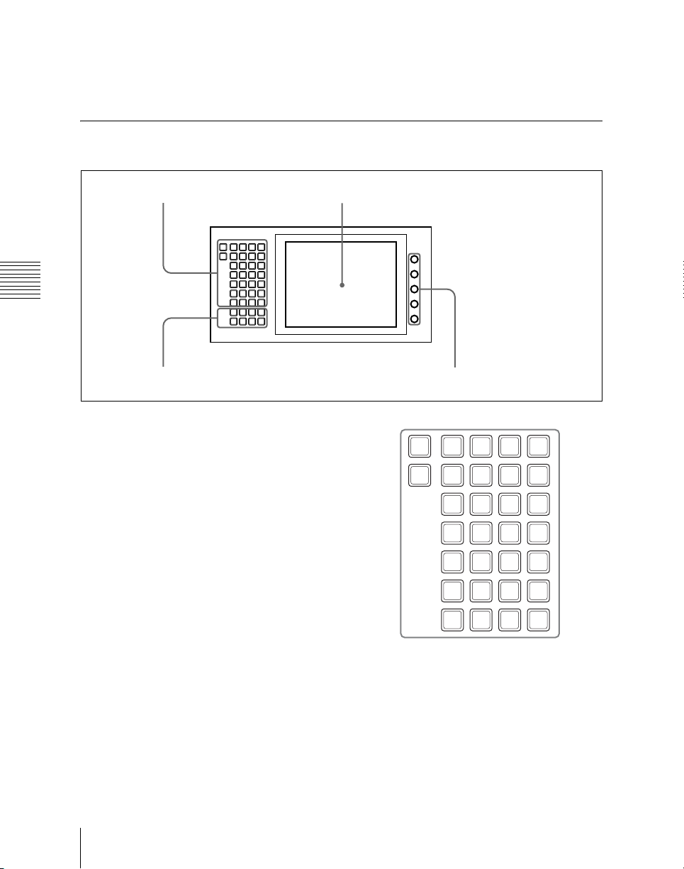
• Every time the button is pressed, it
toggles between the shifted and unshifted
• The button does not take effect even
when pressed.
states for the AUX delegation buttons.
Menu Control Block
2 Menu display1 Top menu selection buttons
M/E1M/E2M/E
P/P
HOME
3
SUB
FRAME
COLOR
AUX
MENU
MEM
BKGD
/MON
SITE
COPY
MISC
SWAP
GLB
DME
EFF
MCRO
RTR DEV
KEY
SHOT
SNAP
EFF
FRAME
BOX
Chapter 2 Menus and Control Panel
a Top menu selection buttons
These select the menu appearing in the
menu display.
It is also possible to change the assignment
of these buttons in setup.
For details, see “Overall Control Panel
Settings (Config Menu)” in Chapter 19
(Volume 3).
SHOT
USER
ENG
FILE
SETUP
SETUP
PREFS1PREFS2PREFS3PREFS
PREFS5PREFS6PREFS7PREFS
DIAG
4
8
3 Knobs4 User preference buttons
M/E
HOME
MENU
SUB
SITE
1
FRAME
COLOR
MEM
BKGD
COPY
MISC
SWAP
GLB
DME
EFF
RTR DEV
AUX
/MON
STATS
P/P
CCR
MCRO
Names and Functions of Parts of the Control Panel
50
KEY
FRAME
FILE
USER
SETUP
EFF
SNAP
SHOT
ENG
SETUP
SHOT
DIAG
BOX
b Menu display
This shows the menu currently in use.
c Knobs
These adjust the parameter values
appearing in the menu.
Page 51
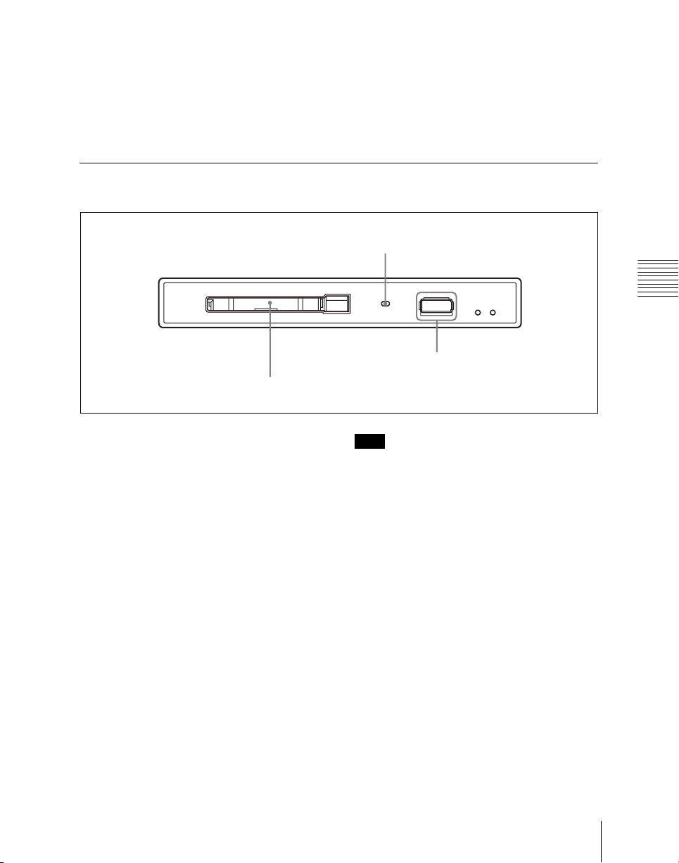
d User preference buttons
These recall the functions or menus
assigned to them in the Setup menu.
In the default setup, nothing is assigned to
the [PREFS 1] to [PREFS 8] buttons.
It is also possible to change the assignment
of these buttons in setup.
For details, see “Overall Control Panel
Settings (Config Menu)” in Chapter 19
(Volume 3).
Memory Card/USB Adaptor Block
1 Memory card slot
3 Memory card access indicator
Chapter 2 Menus and Control Panel
2 DEVICE connector
a Memory card slot
This slot accepts a PCMCIA Type II
compliant memory card. You can use it in
software installation, and for saving and
reading in data, such as snapshot, keyframe,
effect, and setup data.
b DEVICE connectors
This is a USB connector.
You can connect a device such as a mouse,
keyboard, USB storage, and so on, that is
equipped with a USB interface to any of
these connectors.
For details on the devices that can be
connected, consult your Sony
representative.
c Memory card access indicator
This indicator lights when the memory card
is accessed for reading or writing.
Note
When the indicator is lit, do not take out the
memory card.
51Names and Functions of Parts of the Control Panel
Page 52
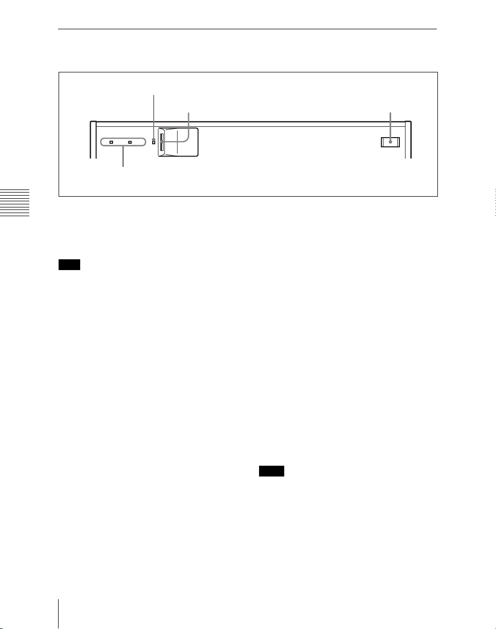
“Memory Stick”/USB Connections Block
1 “Memory Stick” status indicator
2 “Memory Stick” slot
APOWERB
4 POWER A, B status indicators
3 DEVICE connector
Chapter 2 Menus and Control Panel
a “Memory Stick” status indicator
Lights in red during access to a “Memory
Stick.”
d POWER A, B status indicators
The status indicators light in green when
the unit is powered on.
The POWER B status indicator does not
Note
Do not power the unit off or remove a
“Memory Stick” when the “Memory Stick”
light when the optional HK-PSU11 Power
Supply Unit is not supplied in the factory
configuration.
status indicator is lit.
About “Memory Sticks”
b “Memory Stick” slot
Insert “Memory Sticks.” You can use it in
software installation, and for saving and
reading data, such as snapshot, keyframe,
effect, and setup data.
See the next item, “Memory Sticks” for
more information about the usable
“Memory Sticks” and their handling.
c DEVICE connectors
There is a USB connector.
You can connect a device such as a mouse,
keyboard, USB storage, and so on, that is
equipped with a USB interface to any of
these connectors.
For details on the devices that can be
connected, consult your Sony
representative.
Usable “Memory Sticks”
This unit has been confirmed to operate
with those of the following “Memory
Sticks” that have a capacity of 8 GB
(gigabytes) or less. However, operation
with all “Memory Sticks” is not guaranteed.
• “Memory Stick”
• “Memory Stick PRO”
• “Memory Stick Duo”
• “Memory Stick PRO Duo”
Notes
• When using a “Memory Stick PRO,”
high-rate data transfer using parallel
interface is not supported.
• A “MagicGate Memory Stick” can also
be used, but this system does not support
the MagicGate function.
• When using a “Memory Stick Duo,” be
sure to use it with a “Memory Stick Duo
Names and Functions of Parts of the Control Panel
52
Page 53

Adaptor” (MSAC-M2 or equivalent). If
you insert a “Memory Stick Duo”
without using the adaptor, there is the
possibility that the stick cannot be
removed, resulting in a serious accident.
Handling “Memory Sticks”
When using “Memory Sticks,” pay
attention to the following points.
• Do not touch the connector of the
“Memory Stick” with anything, including
your finger or metallic objects.
• Do not attach anything other than the
supplied label to the “Memory Stick”
labeling position.
• Attach the label so that it does not stick
out beyond the labeling position.
• Carry and store the “Memory Stick” in its
case.
• Do not strike, bend, or drop the “Memory
Stick.”
• Do not disassemble or modify the
“Memory Stick.”
• Do not allow the “Memory Stick” to get
wet.
• Do not use or store the “Memory Stick”
in a location that is:
– Extremely hot, such as in a car parked
in the sun
– Under direct sunlight
– Very humid or subject to corrosive
substances
Chapter 2 Menus and Control Panel
53Names and Functions of Parts of the Control Panel
Page 54
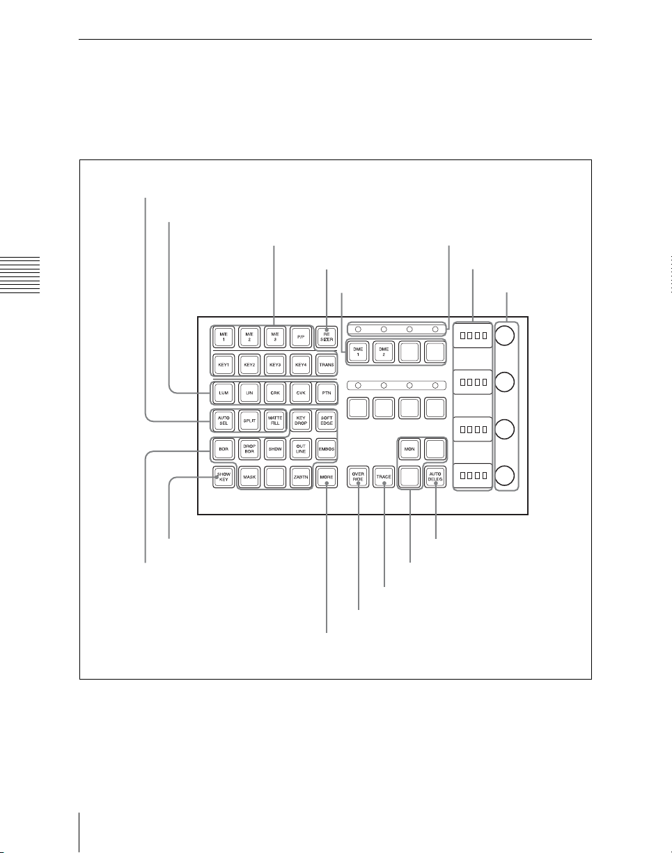
Key Control Block (MKS-8035 Key Control Module, Option)
Each of the M/E and PGM/PST banks
includes four keyers (for keys 1 to 4), and
desired keyer. In this control block, you can
adjust and modify keys.
you can delegate this control block to any
3 Key fill/key source selection buttons
2 Key type selection buttons
1 Delegation buttons
qg RESIZER button
Chapter 2 Menus and Control Panel
9 DME channel
selection buttons
q; ON AIR indicators
8 Displays
7 Knobs
6 SHOW KEY button
4 Key modifier buttons
a Delegation buttons
Key delegation: Press one of the [KEY1]
to [KEY4] buttons to delegate the key
Names and Functions of Parts of the Control Panel
54
qf AUTO DELEG button
qa Output destination specification
buttons
qd TRACE button
qs OVERRIDE button
5 MORE button
control block to the corresponding
keyer.
M/E delegation: Press one of the [M/E 1]
to [M/E 3], and [P/P] buttons to select
Page 55

the bank (the M/E bank or PGM/PST
bank) to which the key control block is
delegated.
Notes
• When the MKS-9011 1M/E Control
Panel is used, only the [P/P] is enabled.
When the MKS-9012 2M/E Control
Panel is used, only the [M/E-1] and [P/P]
are enabled.
• With the MKS-9011/9012, you cannot
directly control DME5 to DME8.
TRANS: By pressing this button, you can
check the DME channel used for DME
wipes on the M/E or PGM/PST bank.
Also, by pressing this button, then
pressing one of the DME channel
selection buttons, you can preset the
DME channel to be used when a DME
wipe is selected as the transition type
for the next transition.
When presetting the DME channel for
an independent key transition, hold
down this button, then press one of the
[KEY1] to [KEY4] buttons, turning the
two buttons on, beforehand.
b Key type selection buttons
Press one of these buttons, turning it on, to
select the desired key type.
Depending on the selected key type,
various parameters are displayed, and you
can set the values with the knobs.
The following key types can be selected.
LUM: luminance key
LIN: linear key
CRK: chroma key
CVK: color vector key
PTN: key wipe pattern key
For details, see “Key Types” (page 141).
c Key fill/key source selection buttons
AUTO SEL (selection): Use the signal
selected on the key fill bus, and the
paired key source signal. The setting of
key fill and key source pairs is carried
out in a Setup menu.
SPLIT: To use the signal selected on the
key fill bus as key fill, and a signal
separate from the signal assigned in a
pair with key fill for key source, press
this button, turning it on.
To use the signal selected on the key fill bus
as key source (self keying), press the
[AUTO SEL] button and [SPLIT] button at
the same time, so that both are off.
MATTE FILL: To use a color matte from
the internal generator as key fill, press
this button, turning it on. You can
adjust the color matte using the knobs.
When this button is off, the signal
selected on the key fill bus is used as
key fill.
d Key modifier buttons
To add an edge modifier to the key, press
one of these buttons, turning it on.
Depending on the edge type selected,
parameters appear in the displays, and you
can set the values with the knobs.
For functions other than MASK, keys 3 and
4 cannot be used.
KEY DROP: When the selected edge type
is “normal” and soft edge is not
selected or when drop border or
shadow is selected, turning this button
on lowers the key fill and key source
position by four or eight scan lines as
set in the key menu.
To select 4H or 8H, use the Key menu.
When the selected edge type is
“normal” and soft edge is selected or
when border, outline, or emboss is
selected, this button lights
automatically.
BDR (border): Apply a border of a
uniform thickness to the whole key.
DROP BDR (drop border): Apply a
border to two sides of the key (for
Chapter 2 Menus and Control Panel
55Names and Functions of Parts of the Control Panel
Page 56

example, below and to the right, or
below and to the left).
SHDW (shadow): Apply a shadow to two
g Knobs
Turn the knobs to adjust the parameter
values.
sides of the key (for example, below
and to the right, or below and to the
left).
OUTLINE: Use the outline of the key.
EMBOS (emboss): Apply an embossing
effect to the periphery of the key.
h Displays
Each display shows the initial letters of the
parameter name and the parameter value
(maximum three digits including a minus
sign for a negative value).
• To select a “normal” as the edge type
(that is, a plain edge), set all five of the
above buttons off.
• When emboss is selected, you can use the
dedicated color matte signal for the
emboss function.
• When outline is selected, the signal
Chapter 2 Menus and Control Panel
selected on the key fill bus is used to fill
the edge.
MASK: Press this button, turning it on, to
enable the key mask using the mask. It
also enables you to set the parameters
with the knobs.
ZABTN (zabton): When this is pressed,
turning it on, a translucent pattern is
inserted behind the key. With the
knobs, you can adjust the color, size,
density, and softness parameters.
SOFT EDGE: Soften the edge of the key.
e MORE button
When there are more than four parameters,
this button lights amber. When it is pressed,
it changes from amber to green and the fifth
and subsequent parameters are assigned to
the knobs, allowing them to be adjusted.
f SHOW KEY button
While this button is held down, a key
processed key source signal is output from
the specified output port. You can make the
output specification independently for each
of edit preview and the preview of the M/E
or PGM/PST bank in a Setup menu.
i DME channel selection buttons
Press one of these buttons, turning it on, to
assign a DME channel to the keyer.
DME1 and DME2 can be assigned to one
keyer.
A DME channel assigned to a keyer cannot
be selected on another keyer. However,
using the override function it is possible to
allocate a channel already allocated to
another keyer to the currently selected
keyer. If DME channel allocations have
been made in a Setup menu, these buttons
cannot be used to make DME channel
allocations. Using the trace function, it is
possible to check which keyer a DME
channel is allocated to.
j ON AIR indicators
These light red when the corresponding
DME channels are included in the final
program output.
k Output destination specification
buttons
MON (DME monitor): Hold down this
button and press the selection button
for the DME channel you want to
assign to the monitor output; you can
then monitor the output signal on the
DME monitor output.
While this button is held down, the
DME channel selection buttons light as
follows, allowing you to check the
monitor assignment.
Lit amber: DME channel that can
currently be monitored
Names and Functions of Parts of the Control Panel
56
Page 57

Lit green: DME channel currently
assigned to the monitor output
l OVERRIDE button
To select a DME channel already allocated
to another keyer or transition to the
currently selected keyer (or transition), hold
down this button, and press the DME
channel selection button.
m TRACE button
When a DME channel is already allocated
to another keyer or transition, hold down
this button, and press the corresponding
DME channel selection button, to switch to
the state in which the keyer (or transition) to
which the DME channel is allocated is
currently selected.
n AUTO DELEG (auto delegation)
button
When this button is on, the key delegation
selection state of the key control block is
linked to the next transition selection state
of the transition control block.
Chapter 2 Menus and Control Panel
o RESIZER button
Enables or disables resizer.
For details on resizer, see page 186.
57Names and Functions of Parts of the Control Panel
Page 58
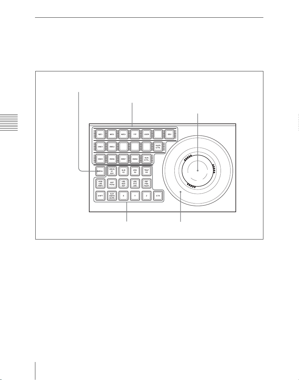
Device Control Block (MKS-8031TB Trackball Module, Option)
The device control block is used for threedimensional transform operations using a
for VTR/disk recorder or frame memory
clip operations.
DME, for wipe pattern position setting, and
5 MENU button
1 Region selection buttons
3 Trackball
Chapter 2 Menus and Control Panel
2 Operating buttons
4 Z-ring
a Region selection buttons
The operation mode allocated to the device
control block depends on the selection state
of the region selection buttons.
When the [M/E 1], [M/E 2], [M/E 3], and
[P/P] buttons are selected: This
enables the wipe pattern position
setting (positioner) operation mode in
the device control block. You can
select multiple buttons simultaneously.
When the MKS-9011 1M/E Control
Panel is used, only the [P/P] is enabled.
When the MKS-9012 2M/E Control
Names and Functions of Parts of the Control Panel
58
Panel is used, only the [M/E-1] and [P/
P] are enabled.
When the [USER] button is selected: This
enables pattern position setting used
for color backgrounds.
When the [DME1], [DME2], and
[DME5] to [DME 8] buttons are
selected: This enables the three-
dimensional transform operation mode
in the device control block.
Press a button, turning it on, to select a
DME channel. You can select multiple
buttons simultaneously.
Page 59

With the MKS-9011/9012 control
panel, you cannot directly control
DME5 to DME8.
When the [DEV] button is selected: This
enables the VTR/disk recorder/frame
memory operation mode in the device
control block. Each button functions as
follows.
(From upper left to right in the above
figure)
[M/E1] to [M/E3]: DEV1 (device 1) to
DEV3 (device 3)
[P/P]: DEV4 (device 4)
[USER]: FM1CLIP (frame memory
clip 1)
[Unused]: FM2CLIP (frame memory
clip 2)
[DME1]: DEV5 (device 5)
[DME2]: DEV6 (device 6)
[Unused]: DEV7 (device 7)
[Unused]: DEV8 (device 8)
[Unused]: FM LOOP (frame memory
loop)
[DME5] to [DME8]: DEV9 (device 9)
to DEV12 (device 12)
To exit from this mode, press the
[DEV] button again, turning it off.
When the [RUN CTRL] button is
selected: This enables the effect run
control mode in the device control
block.
When the [RSZR CTRL] button is
selected: This enables the resizer
control mode in the device control
block.
For details on resizer, see page 186.
The functions of the operation buttons,
trackball, and Z-ring vary with the
operation mode as follows.
b Operation buttons
When the positioner operation mode is
enabled
K1 CB1: Press this button to enable wipe
pattern position setting for key 1
(DSK1).
When the [USER] button is selected,
pattern position setting for color
background 1 is enabled.
K2: Press this button to enable wipe pattern
position setting for key 2 (DSK2).
K3: Press this button to enable wipe pattern
position setting for key 3 (DSK3).
K4: Press this button to enable wipe pattern
position setting for key 4 (DSK4).
WIPE: Press this button to enable wipe
pattern position setting for normal
transitions.
Among the [K1 CB1] button, [K2] button,
[K3] button, [K4] button, and [WIPE]
button, you can select multiple buttons.
POS: Press this button to enable pattern
movement in the x-axis and y-axis
directions with the trackball.
When the [USER] button is selected,
this enables the trackball to move the
pattern in the x-axis and y-axis
directions, and the Z-ring to adjust the
size of the pattern.
X, Y: These restrict the axes affected by the
trackball and Z-ring to the x- or y-axis.
Z: This restricts the axes affected by the
trackball and Z-ring to the z-axis.
CTR (center): When this button is pressed,
the pattern position returns to the
center. When the [USER] button is
selected, the pattern size also returns to
50.00.
SHIFT/CLR WORK BUFR: These are
not used in positioner operation mode.
When the three-dimensional transform
operation mode is enabled
The Buttons are used for three-dimensional
DME transformations.
Chapter 2 Menus and Control Panel
59Names and Functions of Parts of the Control Panel
Page 60

For details, see “Basic Operations” in
Chapter 11 (Volume 2).
c Trackball
When the positioner operation mode is
enabled
When the VTR/disk recorder/frame
memory operation mode is enabled
By moving this, you can move the pattern
in the x-axis and y-axis directions.
The Buttons are used for VTR control or
playback of frame memory clips.
For details, see “Controlling the Tape/Disk
Transport” in Chapter 12 (Volume 2).
When the resizer control mode is enabled
LOCAL (K1): Select key 1.
GLB (K2): Select key 2.
LOC SIZE (ASP: aspect): Pressing this
button and operating the trackball or Z-
Chapter 2 Menus and Control Panel
ring changes the aspect ratio of a key to
which the resizer function is applied to.
When this button is held down, the
trackball or Z-ring operation is
switched to a finer control. (fine mode)
LOC XYZ (LOC: location): Pressing this
button and operating the trackball or Zring moves, shrinks, or magnifies a key
to which the resizer function is applied
to. When this button is held down, the
trackball or Z-ring operation is
switched to a finer control. (fine mode)
ROT (RSZE: resizer): Press this button,
turning it on, to enable the resizer.
CLR WORK BUFR (clear work buffer):
Pressing this button once returns the
two-dimensional transformation
settings to the defaults. Pressing twice
in rapid succession returns all resizer
parameter values to the defaults.
X, Y: These restrict the axes affected by the
trackball and Z-ring to the x- or y-axis.
Z: This restricts the axes affected by the
trackball and Z-ring to the z-axis.
CTR (center): Pressing this button once
changes the two-dimensional
transformation settings to the closest
detent values. Pressing twice in rapid
succession returns the two-dimensional
transformation settings to the defaults.
When the three-dimensional transform
operation mode is enabled
Move the trackball to control the x- and y-
axes in a three-dimensional transform.
When the [SRC] or [TRGT] button is held
down, the trackball operation is switched to
a finer control. (fine mode)
When the resizer control mode is
enabled
By turning the trackball, you can move in
the x- and y-directions of the key to which
the resizer is applied, and change the aspect
ratio.
When the [LOC SIZE] or [LOC XYZ]
button is held down, the trackball operation
is switched to a finer control. (fine mode)
d Z-ring
When the positioner operation mode is
enabled
When the [USER] button is selected, by
turning the ring you can adjust the size of
the pattern.
When the three-dimensional transform
operation mode is enabled
Turn this ring to control the z-axis in a
three-dimensional transform.
When the [SRC] or [TRGT] button is held
down, the Z-ring operation is switched to a
finer control. (fine mode)
When the effect run control mode is
enabled
By turning the Z-ring, you can run the
keyframe effect, independent of the STOP
NEXT KF, EFF LOOP, and similar settings
in the keyframe control block. Turn
clockwise to run the effect in the normal
Names and Functions of Parts of the Control Panel
60
Page 61

direction, and counterclockwise for the
reverse direction.
normal direction, and counterclockwise for
the reverse direction.
When the resizer control mode is enabled
By turning the ring, you can zoom the key
to which the resizer is applied, and change
the aspect ratio.
When the [LOC SIZE] or [LOC XYZ]
button is held down, the Z-ring operation is
switched to a finer control. (fine mode)
e MENU button
Press this button, turning it on, to enable
adjusting the parameters allocated to the
knobs in the menu using the trackball and
Z-ring.
In the case of the DME menu, the operation
applies to the selected DME channel.
In VTR/disk recorder/frame memory
When the VTR/disk recorder/frame
memory operation mode is enabled
Turning the Z-ring controls the tape
transport/disk drive/frame memory clip
operations, at a speed determined by the
operation mode, press this button, setting it
to On, to make it possible to carry out
timeline start/stop point setting operation
for the device selected with the device
selection buttons (timeline setting mode).
operating buttons. Turn clockwise for the
Device Control Block (MKS-8036A Search Dial Module, Option)
Using the device control block (MKS8036A search dial module
can directly operate an XDCAM, disk
recorder, VTR or other external device,
frame memory clip, or shotbox. The device
control block (MKS-8031TB track ball
module, option) can be used together.
1)
, option), you
Chapter 2 Menus and Control Panel
1) The product name of the MKS-8036A is “device
control module,” but in this manual it is referred to
as “search dial module” to distinguish it from the
MKS-8031TB trackball module.
61Names and Functions of Parts of the Control Panel
Page 62
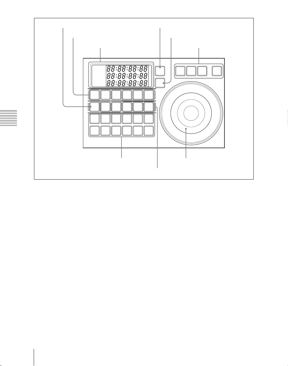
4 DELAY button
2 Device selection buttons
7 TIMELINE button
8 STOP button
1 Timecode display
6 External device
operation buttons
CURRENT
START TC
STOP TC
DEV
DEV2DEV3DEV4DEV5DEV
1
FM1
FM2
DELAY
CLIP
STARTTCSTOP
TC
Chapter 2 Menus and Control Panel
SBOX1SBOX2SBOX
CLIP
SET
START
STOP
TC
SET
SET
DUR
TC
ALL
STOP
5 Editing
buttons
a Timecode display
This shows the current time (CURRENT)
and the start and stop point timecode values
TIME
LINE
STOP
6
3
STB
OFF
RECPLAY FFREWCUE
SHTL JOG VAR ENBL
9 Search dial
3 SBOX buttons
When the [TIMELINE] button is off:
Displays the Cueup & Play (rewind
action) start and stop points.
for the current reference device (START
TC, STOP TC). When you press a device
selection button, the button lights, selecting
the assigned device as the reference device,
and displaying its setting value.
In the case of the [SBOX] buttons, the
display does not change. The displayed
setting value depends on whether the
[TIMELINE] button is on or off, as follows.
b Device selection buttons
These buttons are used for selecting
assigned external devices or frame memory
clips. Each button can only be assigned to a
single device. Carry out the assignment in
the Setup menu (see “Overall Control
Panel Settings (Config Menu)” in Chapter
19 (Volume 3)). To select an assigned
device, press the corresponding button,
When the [TIMELINE] button is on:
Displays the start and stop points of the
last set keyframe on the timeline. When
the keyframe number is changed and
the last register and keyframe change,
the display also changes. (timeline
setting mode)
which lights green. To select more than one
device simultaneously, hold down the
button for the first selection, while pressing
the buttons for the other selections in turn.
The second and subsequent selected
buttons light amber. If you press another
button without holding down the first
selected button, the second button will be the reference device and light green.
Names and Functions of Parts of the Control Panel
62
Page 63

DEV: Assign external devices DEV1 to
DEV12.
FM CLIP: Assign frame memory clips
FM1 to FM8.
Device selection buttons can be set as
SBOX buttons or DELAY button in the
Setup menu.
c SBOX (shotbox) buttons
Assign a shotbox saved in registers 1 to 99.
When you press a button, the assigned
shotbox is selected, and executed.
SBOX buttons can be set as device
selection buttons or DELAY button in the
Setup menu. Carry out the assignment in
the Setup menu (see “Overall Control
Panel Settings (Config Menu)” in Chapter
19 (Volume 3)).
d DELAY button
When pressed, this button lights green, the
numeric keypad control block display
changes to DELAY__ : , and you can set
the start delay time for the selected device.
The setting range is from 00:00 to 59:29
(depends on the video format). This button
goes off when another timecode setting
button ([START TC], [STOP TC], [SET
START TC], [SET STOP TC], or [SET
DUR]) is pressed.
The DELAY button can be set as a device
selection button or an SBOX button in the
Setup menu. Carry out the assignment in
the Setup menu (see “Overall Control
Panel Settings (Config Menu)” in Chapter
19 (Volume 3)).
e Editing buttons
These carry out Cueup & Play (rewind
action) operations on material, and timeline
settings. These operations are only valid
while a device is selected with the device
selection buttons.
START TC: When pressed, this button
flashes amber, and sounds a beep,
setting the timecode at that time as the
device start point (on the timeline when
the [TIMELINE] button is On, and
Cueup & Play start point when Off). If
you press once more, the timecode at
that time is overwritten as a new start
point.
STOP TC: When pressed, this button
flashes amber, and sounds a beep,
setting the timecode at that time as the
device stop point (on the timeline when
the [TIMELINE] button is On, and
Cueup & Play stop point when Off). If
you press once more, the timecode at
that time is overwritten as a new stop
point.
SET START TC, SET STOP TC, SET
DUR: When pressed, these buttons
light green, “START TC”, “STOP TC”
or “DUR” appears in the numeric
keypad control block display, and you
can enter a timecode from the numeric
keypad. If you enter a numeric value
and press the [ENTER] button, the
button goes off, whereas if you press
the [ENTER] button without entering a
numeric value the numeric keypad
control block display shows
“--:--:--:--”. To exit the numeric value
entry mode, either repeat pressing the
same button, or press a different
numeric keypad control block linked
button, or a mode selection button such
as the [EFF] and [SNAPSHOT]
buttons in the numeric keypad control
block. If the timecode has been set
correctly, the entered numeric value
appears in the timecode display.
STB (standby) OFF: When pressed, this
button flashes amber, and the device
selected with the device selection
buttons exits from the standby mode.
This button cannot be used for frame
memory clip operations.
CUE: When pressed, this button flashes
amber together with the [ALL STOP]
Chapter 2 Menus and Control Panel
63Names and Functions of Parts of the Control Panel
Page 64

button, and the device selected with the
device selection button is cued up to the
start point of the material. When more
than one device is selected, the amber
flashing continues until the reference
device is cued up, and when the cueing
up is finished, this button lights green.
REW: When pressed, this button lights
amber, and material of the device
selected with the device selection
f External device operation buttons
ENBL (enable): When this is pressed,
turning it on, the search dial [VAR],
[JOG], and [SHTL] button operations
are enabled.
VAR (variable): Sets the search dial to
variable mode.
JOG: Sets the search dial to jog mode.
SHTL (shuttle): Sets the search dial to
shuttle mode.
buttons is rewound. To stop during the
rewind, press the [STOP] button or
[ALL STOP] button.
PLAY: When pressed, this button lights
amber, and the device selected with the
Chapter 2 Menus and Control Panel
device selection buttons plays. The
playback stops not only if the [STOP]
button is pressed, but also if any of the
[STB OFF], [SHTL], [JOG], [CUE],
[REW], [PLAY], [FF], and [ALL
g TIMELINE button
Press to switch the device selected with the
device selection buttons to timeline setting
mode.
h STOP button
When pressed, this lights amber, and
operation of the device selected with the
device selection buttons stops.
STOP] buttons is pressed. When the
[VAR] button is pressed while the
device is playing back, the device plays
at one times normal speed in variable
mode.
FF: When pressed, this button lights amber,
and the material of the device selected
with the device selection buttons is fast
i Search dial
Use this for search and other operations on
the material of an external device.
For details of the method of use, see
“Controlling Tape/Disk Transport” in
Chapter 12 (Volume 2).
forwarded. To stop during the fast
forward, press the [STOP] button or
[ALL STOP] button.
ALL STOP: When pressed, all device
material playback and other operations
stop. During cueing up of any of the
devices, this button flashes amber, and
when all cueing up operations are
completed, it lights green.
REC: When pressed simultaneously with
the [PLAY] button, this button lights
red (the [PLAY] button lights amber),
and the image from the selected device
is recorded.
This button cannot be used for frame
memory clip operations.
Names and Functions of Parts of the Control Panel
64
Page 65
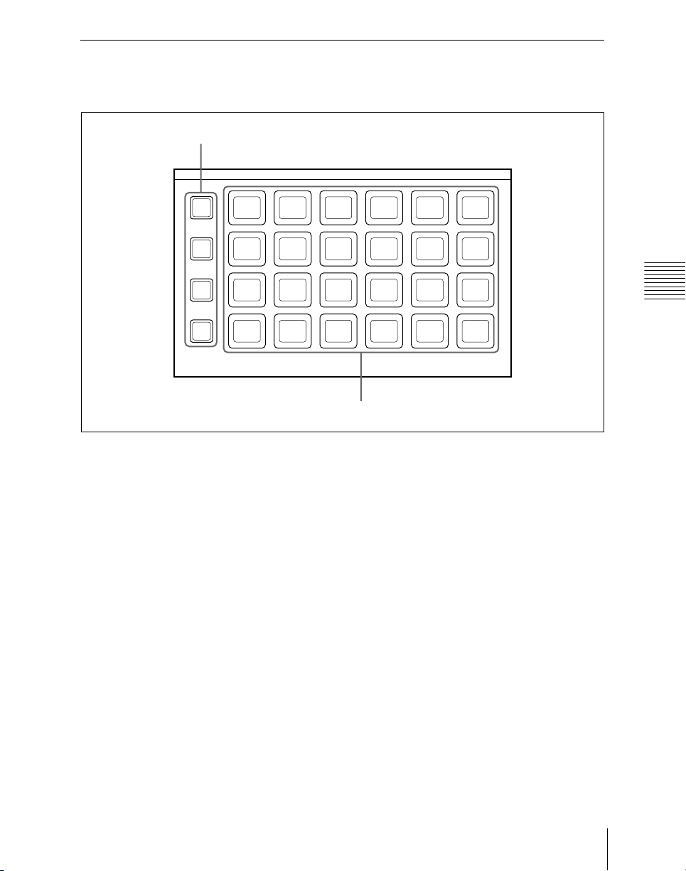
Utility/Shotbox Control Block (MKS-8033 Utility/ Shotbox Module, Option)
1 Bank selection buttons
BANK
BANK
BANK
BANK
1
2
3
4
1
7
13 14 15 16 17 18
19 20 21 22 23 24
2 3 4
8 9 10 11 12
a Bank selection buttons
Press any of the [BANK1] to [BANK4]
buttons to select a bank of 24 memory recall
buttons. The selected button lights amber.
b Memory recall buttons
You can use these buttons to recall
frequently used menus, utility functions,
shotbox registers, or macro registers that
you have assigned.
When a utility function is allocated to a
button, the button lights orange (or green
depending on the status), and the allocated
function name appears. Pressing the button
executes the allocated function. When the
function constitutes a switching on/off
operation, the button lights green;
otherwise, it only momentarily lights green.
When a shotbox register or macro register
recall is assigned to a button, the button
56
Chapter 2 Menus and Control Panel
2 Memory recall buttons
lights orange, and the assigned register
name appears. (If the register is empty, the
button goes off.) In the case of a shotbox
function, pressing the button executes the
assigned shotbox function, and the button
lights yellow. In the case of a macro
register, pressing the button executes the
assigned macro, and the button flashes
yellow.
65Names and Functions of Parts of the Control Panel
Page 66
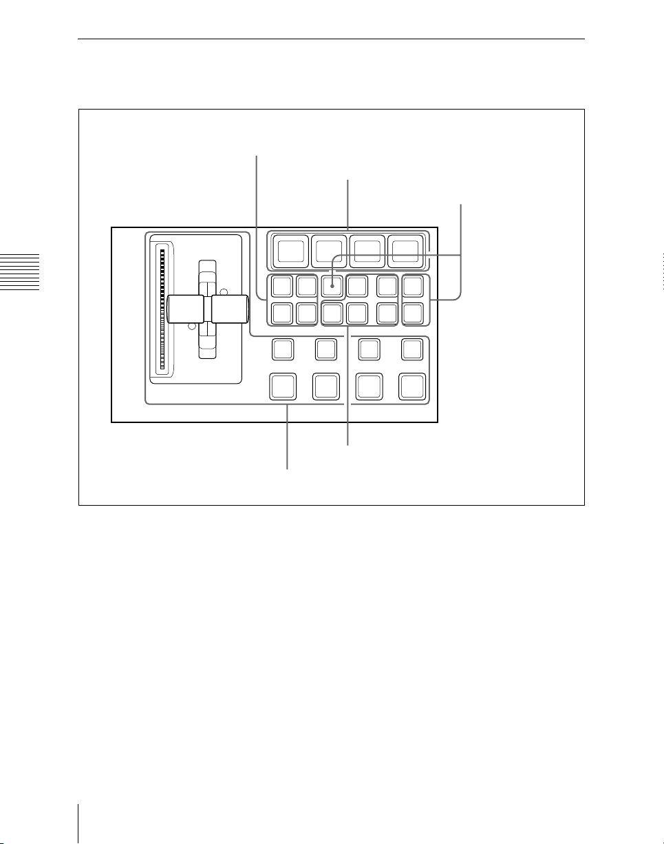
Downstream Key Control Block (MKS-8032 DSK Fader Module, Option)
1 Key delegation buttons
5 Key source name display/key snapshot
buttons
4 Key snapshot setting
buttons
Chapter 2 Menus and Control Panel
DSK1 DSK2 WIPEUNDO
DSK3 DSK4 SHIFT MIX
DSK1
ON
DSK2
ON
DSK3
K-SS
DME
K-SS
CUT
STORE
DSK4
ON
ON
TAKETAKETAKETAKE
2 Independent key transition type
selection buttons
3 Independent key transition execution section
a Key delegation buttons
Press one of the [DSK1] to [DSK4] buttons
to delegate this control block to the
corresponding keyer.
When the MKS-9012 2M/E Control Panel
is used, it is possible to delegate this control
block to key 1 to key 4 of the M/E bank
using a Setup menu.
MIX: Carry out a dissolve with the key
selected with the key delegation
buttons.
WIPE: Carry out a wipe with the key
selected with the key delegation
buttons.
DME: This switches the key selected with
the key delegation buttons, using a
DME wipe.
b Independent key transition type
selection buttons
Press one of these buttons, turning it on, to
select the downstream key transition type.
CUT: Instantaneously insert or delete the
key selected with the key delegation
buttons.
SHIFT: When setting is made in the Setup
menu to allow a different transition
type for inserting or deleting a key, it is
Names and Functions of Parts of the Control Panel
66
Page 67

possible to display and set the
transition after the next transition while
this button is held down.
c Independent key transition
execution section
DSK1 (downstream key 1) ON to DSK4
ON buttons: Press these to
instantaneously cut the downstream
keys 1, 2, 3, and 4 in or, when the
downstream keys are already inserted,
cut them out. When the key
corresponding to the button appears in
the final program output, the button
lights red, and otherwise lights amber.
TAKE buttons: These correspond to
downstream keys 1, 2, 3, and 4 from
left to right; press to execute an auto
transition. The transition starts
immediately, and the button lights
amber. When the transition completes,
the button goes off.
Fader lever: Move this to carry out a
manual downstream key transition.
Transition indicator: This comprises
multiple LEDs, which show the
progress of the downstream key
transition.
the selected keyer, and pressing the button
saves or recalls a key snapshot.
Chapter 2 Menus and Control Panel
d Key snapshot setting buttons
K-SS (key snapshot): This enables key
snapshot mode.
K-SS STORE (key snapshot store): To
save a key snapshot, hold down this
button, and press the key source name
display/key snapshot button for the
register you want to save.
UNDO (key snapshot recall undo): This
undoes the last key snapshot recall.
e Key source name display/key
snapshot buttons
These display the selected source name for
each corresponding keyer. In snapshot
mode, they correspond to registers 1 to 4 of
67Names and Functions of Parts of the Control Panel
Page 68
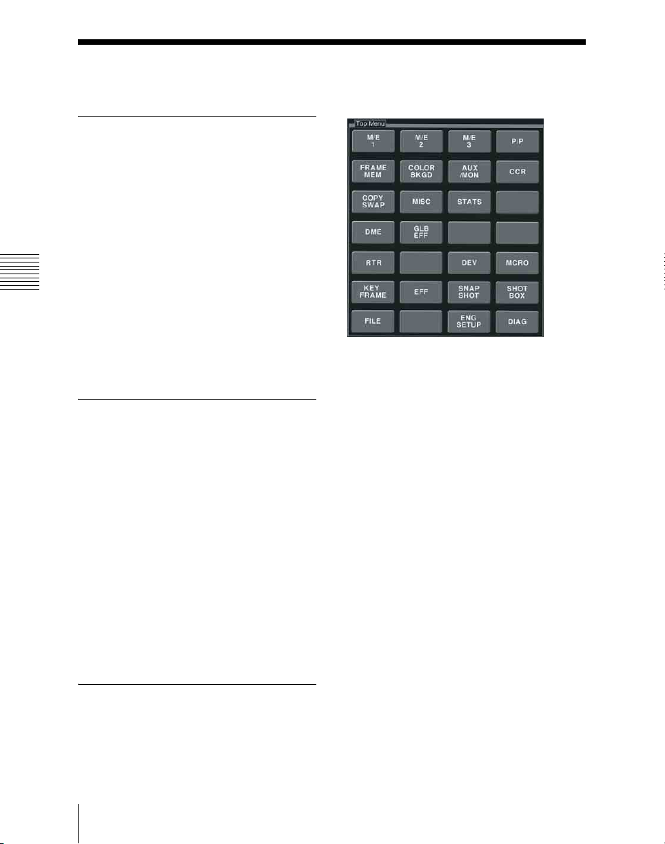
Basic Menu Operations
Menu Organization
Operations on the MVS-6000 switcher
system make frequent use of menu
operations.
This section describes the menus and their
interrelationships.
Overview
Chapter 2 Menus and Control Panel
All detailed settings for basic operations
such as transitions, keys, DME, or wipes,
are made in menus. There are also menus
for carrying out general system control,
managing setting data, and initial setup.
About the Top Menu List
When the control panel is powered on, the
top menu list appears as shown below.
You can also display this by selecting VF1
‘Top Menu List’ after pressing the [HOME]
button at the upper left in the top menu
selection button area of the menu control
block.
To display the top menu
In the same way as for the top menu
selection buttons in the menu control block,
press each button to display the particular
top menu in the menu display.
The top menu list button is the same as the
default layout of the top menu selection
buttons. However, even if the assignment of
the top menu selection buttons is changed,
this does not affect the top menu list.
To shut down the menus
Press the [Shutdown] button at the lower
right.
This operation is the same as the shut down
operation in the top menu window.
Accessing Menus
You can use any of the following methods
to access a menu, and the initially displayed
Basic Menu Operations
68
For details, see “Shutting down the menus”
(page 87).
menu page depends on the method used.
• Pressing a top menu selection button in
the menu control block.
This displays the page you last accessed
in the particular menu. After initially
Page 69

powering on the system, however, the
page of VF1 - HF1 of the particular menu
is always selected.
• Pressing a button other than a top menu
button twice in rapid succession (see
page 71).
Depending on the button, this may
display a fixed page or the page selected
last time you accessed the menu.
• Press the menu page selection button at
the top left of the menu display.
The top menu window appears; press the
top menu selection button for the
particular menu, or enter the menu
number with the numeric keypad, and
press the Enter button.
For details of the VF buttons and HF
buttons, see “Interpreting the Menu
Screen” (page 75).
Chapter 2 Menus and Control Panel
69Basic Menu Operations
Page 70
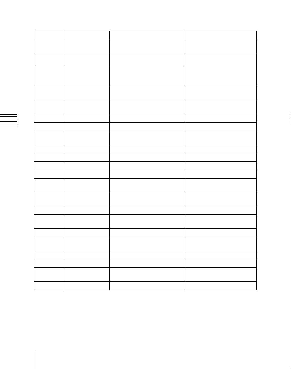
Menus accessed from a top menu selection button
Buttons Menus Function See
HOME Home Recalling menus using the top
M/E 1 M/E-1 Transition, keys, and wipe
P/P PGM/PST Transition, downstream key, and
FRAME
MEM
COLOR
BKGD
AUX/MON Aux/Mon AUX bus settings page 323
Chapter 2 Menus and Control Panel
CCR CCR Color corrector settings page 331
COPY
SWAP
MISC Misc Safe title settings page 320
STATS Status Status display page 324
DME DME DME special effect settings Chapter 11 (Volume 2)
GLB EFF Global Effect Global effect settings Chapter 11 (Volume 2)
RTR Router Destination, source and level
DEV Device Settings for external device
MCRO Macro Macro register settings Chapter 16 (Volume 2)
KEY
FRAME
EFF Effect Keyframe effect register settings Chapter 13 (Volume 2)
SNAP
SHOT
SHOTBOX Shotbox Shotbox register settings Chapter 15 (Volume 2)
FILE File File settings Chapter 17 (Volume 2)
ENG
SETUP
DIAG Diagnosis Status information display Appendix (Volume 3)
Frame Memory Frame memory settings page 259
Color Bkgd Color background settings page 308
Copy/Swap Copy and swap settings page 312
Key Frame Keyframe settings Chapter 13 (Volume 2)
Snapshot Snapshot register settings Chapter 14 (Volume 2)
Engineering Setup Setup functions Chapter 18 to Chapter 24
menu list or shortcut menu
settings for the M/E-1 bank
wipe settings for the PGM/PST
bank
selections
operation
Top menu list: page 68 Shortcut
menu: page 89
page 114 (transitions), page
142 (keys), page 201 (wipes)
page 325
Chapter 12 (Volume 2)
(Volume 3)
Basic Menu Operations
70
Page 71
Menus accessed by pressing a button twice
For relevant buttons other than the top
menu selection buttons, pressing twice in
rapid succession directly recalls a related
menu page. The following table lists these
Cross-point control block
Buttons Menus See
FM1 to 8 signals assigned
buttons
Color Bkgd1 signal assigned
button
CCR1 signal assigned button CCR >CCR1 >XX Chapter 19
CCR2 signal assigned button CCR >CCR2 >XX
DME1 to DME2 DME >XX Chapter 11
KEY1 to KEY4 (DSK1 to
DSK4)
Buttons Menus See
KEY1 (DSK1) • M/E-1 >Key1 >XX
KEY2 (DSK2) • M/E-1 >Key2 >XX
KEY3 (DSK3) • M/E-1 >Key3 >XX
KEY4 (DSK4) • M/E-1 >Key4 >XX
WIPE M/E-1, PGM/PST >Wipe >Main Pattern page 201
DME M/E-1, PGM/PST >DME Wipe >XX page 232
SUPER MIX M/E-1, PGM/PST >Misc >Transition page 115
PST COLOR MIX M/E-1, PGM/PST >Misc >Transition page 116
FM1&2 CLIP,
FM3&4 CLIP,
FM5&6 CLIP,
FM7&8 CLIP
PRIOR SET M/E-1, PGM/PST >Misc >Key Priority page 111
KEY PRIOR M/E-1, PGM/PST >Misc >Next Key Priority page 112
Frame Memory >Still >Recall page 269
Color Bkgd >Color Bkgd1 page 308
• M/E-1 >Key1, 2, 3, 4 >XX
• PGM/PST >DSK1, 2, 3, 4 >XX
Transition control block
• PGM/PST >DSK1 >XX
• PGM/PST >DSK2 >XX
• PGM/PST >DSK3 >XX
• PGM/PST >DSK4 >XX
M/E-1, 2, 3, PGM/PST >Misc >ClipTransition page 296
buttons of each control block, together with
the menus they recall. (XX represents the
HF menu recalled last in the VF menu.)
(Volume 3)
(Volume 2)
page 148
page 148
Chapter 2 Menus and Control Panel
71Basic Menu Operations
Page 72
Key control block
a)
Buttons Menus See
KEY1 • M/E-1 >Key1 >XX
page 148
• PGM/PST >DSK1 >XX
KEY2 • M/E-1 > Key2 > XX
• PGM/PST >DSK2 >XX
KEY3 • M/E-1 >Key3 >XX
• PGM/PST >DSK3 >XX
KEY4 • M/E-1 >Key4 >XX
• PGM/PST >DSK4 >XX
LUM • M/E-1 >Key1, 2, 3, 4 >Type
LIN
• PGM/PST >DSK1, 2, 3, 4 >Type
page 149
CVK
Chapter 2 Menus and Control Panel
PTN
CRK • M/E-1 >Key 1, 2, 3, 4 >Type >Chroma Adjust
page 154
• PGM/PST >DSK1, 2, 3, 4 >Type >Chroma Adjust
a) The menu recalled depends on which of the M/E delegation buttons and key delegation buttons
are selected in the key control block.
Numeric keypad control block
Buttons Menus See
EFF
SNAPSHOT
• Effect >Effect 1-99 >XX
• Effect >Master Timeline >Store
• Snapshot >Snapshot >XX
b)
c)
b)
• Snapshot >Master Snapshot >Store
c)
Chapter 13
(Volume 2)
Chapter 14
(Volume 2)
SHOTBOX Shotbox >Register >Store/Recall Chapter 15
(Volume 2)
MCRO Macro >Register >XX Chapter 16
(Volume 2)
TRANS RATE
STORE RCALL
a)
Misc >Transition page 122
Key Frame >Region Select
d)
Chapter 13
(Volume 2)
a) The menu recalled depends on which of the M/E-1 bank and PGM/PST bank the numeric
control block is delegated to.
b) When other than [MASTR] is selected with the region selection buttons.
c) When [MASTR] is selected with the region selection buttons.
d) When the [SNAPSHOT] button or [EFF] button is set to On, or lit green.
Basic Menu Operations
72
Page 73
Downstream key control block
a)
Buttons Menus See
DSK1 • M/E-1 >Key1 >XX
page 148
• PGM/PST >DSK1 >XX
DSK2 • M/E-1 >Key2 >XX
• PGM/PST >DSK2 >XX
DSK3 • M/E-1 >Key3 >XX
• PGM/PST >DSK3 >XX
DSK4 • M/E-1 >Key4 >XX
• PGM/PST >DSK4 >XX
WIPE • M/E-1 >Key1, 2, 3, 4 >Transition >Wipe Adjust
page 213
>Pattern Select
• PGM/PST >DSK1, 2, 3, 4 >Transition >Wipe
Adjust >Pattern Select
DME • M/E-1 >Key1, 2, 3, 4 >Transition >Wipe Adjust
page 242
>Pattern Select
• PGM/PST >DSK1, 2, 3, 4 >Transition >DME Wipe
Adjust >Pattern Select
K-SS STORE
b)
Snapshot >Key Snapshot >XX Chapter 14
(Volume 2)
a) The menu recalled depends on which of keyers 1 to 4 the downstream key control block is
delegated to.
b) Recalling is possible only when the [K-SS] button is On.
Auxiliary bus control block
Chapter 2 Menus and Control Panel
Buttons Menus See
FMS1, FMS2 Frame Memory >Still >Freeze/Store page 265
FM1 to 8 signals assigned
Frame Memory >Still >Recall page 269
buttons
Color Bkgd1 signal assigned
Color Bkgd >Color Bkgd1 page 308
button
CCR1 signal assigned button CCR >CCR1 >XX page 331
CCR2 signal assigned button CCR >CCR2 >XX
Device control block (trackball)
Buttons Menus See
DME1, DME2 DME >XX Chapter 11
(Volume 2)
DEV1 to DEV12 assigned
buttons
FM1CLIP to FM8CLIP
• Device >DDR/VTR >Cueup & Play
• Device >DDR/VTR >Timeline
b)
c)
Frame Memory >Clip >Recall page 284
Chapter 12
(Volume 2)
assigned buttons
73Basic Menu Operations
Page 74
Device control block (trackball)
Buttons Menus See
K1, K2 • M/E-1, 2, 3 >Key1, 2, 3, 4 >Processed Key
a) When the [MENU] button is Off.
b) When the [MENU] button is On.
Buttons Menus See
DEV1 to DEV12
FM1CLIP to FM8CLIP
assigned buttons
Chapter 2 Menus and Control Panel
a) When the [TIMELINE] button is Off.
b) When the [TIMELINE] button is On.
• PGM/PST >DSK1, 2, 3, 4 >Processed Key
Device control block (search dial)
• Device >DDR/VTR >Cueup & Play
• Device >DDR/VTR >Timeline
Frame Memory >Clip >Recall page 284
a)
b)
page 186
Chapter 12
(Volume 2)
Displaying a Menu
To display, for example, the M/E-1 >Key1
>Type menu, use either of the following
operations.
• Press the top menu selection button [M/E
1], then press the VF1 ‘Key1’ button and
the HF1 ‘Type’ button in that order.
• Press the menu page number button in the
upper left corner of the menu screen to
display the top menu window, then enter
the page number of the M/E-1 >Key1
>Type menu, which is 1111, and press
the [Enter] button.
For details of the menu page numbers, see
“Menu Tree” (page 372).
The M/E-1 >Key1 >Type menu appears in
the menu display as follows.
Basic Menu Operations
74
Page 75
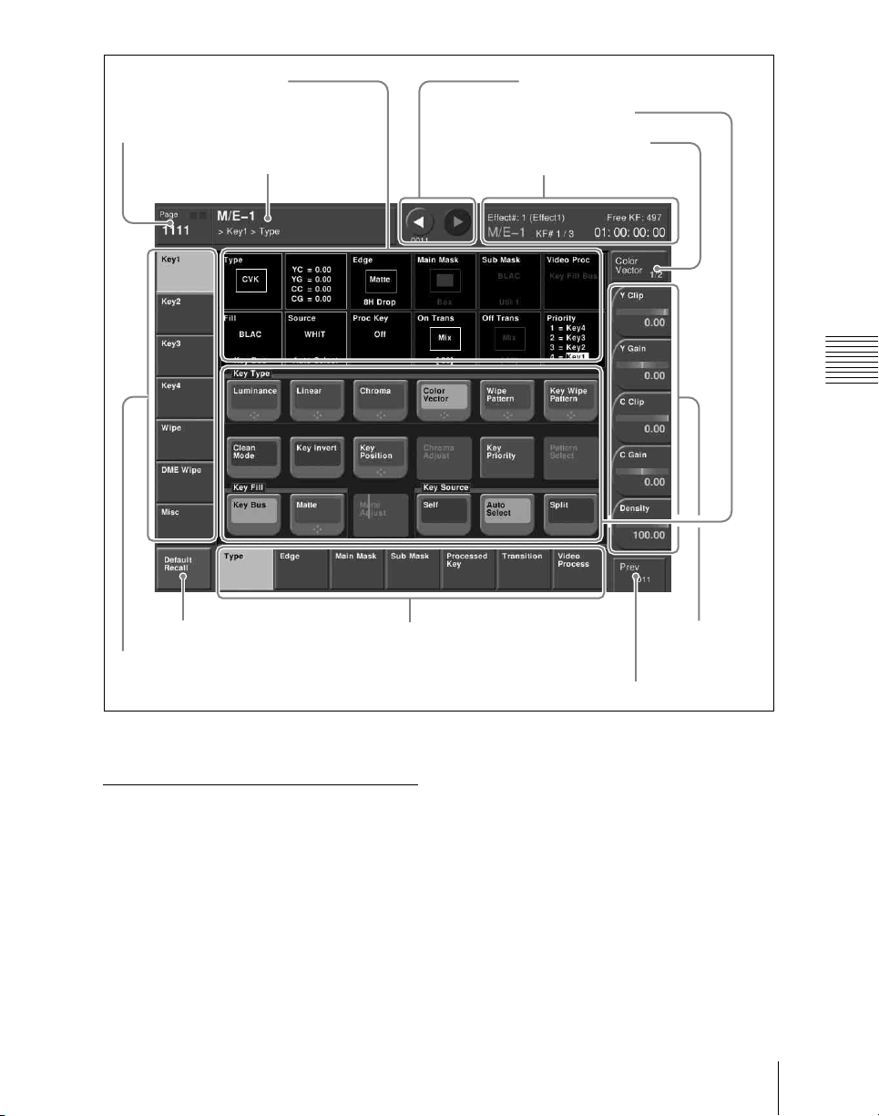
5 Status area
2 Menu page number button
1 Menu title
button
qs b (previous) button and B (next)
6 Function button area
7 Parameter group button
button
0 Keyframe status
Chapter 2 Menus and Control Panel
qa Default recall button
3 VF buttons
M/E-1 >Key1 >Type menu
Interpreting the Menu Screen
The menu screen consists of the following
principal parts.
When buttons on the screen are lit or
represented in a depressed state, this
indicates that the corresponding item or
function is selected (set on).
4 HF buttons
a Menu title button
This shows the title of the menu screen.
You can set different colors for the main
menu site and subsidiary menu site (see
page 89).
b Menu page number button
This shows the menu screen page number.
When you press this button, the top menu
window (see page 86) appears. You can
enter the page number for the desired menu,
8 Knob
parameter
buttons
9 Previous page button
75Basic Menu Operations
Page 76
or press one of the top menu selection
buttons in the window, to display that
pressing the display jumps to the related
menu.
menu.
While the system is accessing the hard disk,
the indicator lights red.
f Function button area
This shows the functions which can be
operated in the currently selected menu by
Indicator for frame
memory external hard disk
Indicator for internal hard
disk
means of buttons.
Each function button corresponds to a
function which can be set in the currently
selected menu. Press it to enable the
function, to display a parameter group and
adjust the parameters with the knobs, or to
execute the function.
Note
When the indicator is lit, do not power off
the switcher, or disconnect the IEEE1394
Chapter 2 Menus and Control Panel
cable
1)
.
These buttons are in groups by function. In
the screen example shown on the previous
page, the [Key Bus] and [Matte] function
buttons constitute the <Key Fill> group.
1) When an external hard disk drive is connected
c VF buttons
These indicate the larger subdivisions of
this menu.
Depending on the selected item, the menu
screen contents including the HF button
indications change.
d HF buttons
These indicate the items within the menu.
Depending on the selected item, the menu
indications change.
Depending on the function, if any one is on,
the status is shown by an orange bar, as in
the following figure.
e Status area
This shows the status of the settings items
controlled by the selected menu.
An orange frame appears around the
parameter area relating to the displayed
menu. For each of the twelve areas,
g Parameter group button
This displays parameter group names for
which the knobs can make adjustments, the
current parameter setting page number, and
the total number of the parameter setting
pages. (Example: Color Vector 1/2)
When there are more than five parameters
within the same parameter group, press this
button to display the sixth and subsequent
parameters, which can then be controlled
by the knobs.
h Knob parameter buttons
These show the parameters currently
controlled by the knobs and their values.
Pressing one of these buttons displays the
numeric keypad window (see page 83), and
you can then enter a new value for the
corresponding parameter with the numeric
keypad.
i Previous page button
This shows the page number of the
previously displayed menu screen. Press it
to go back to that page. When the indication
[Parent] appears, this displays the parent
directory.
Basic Menu Operations
76
Page 77
j Keyframe status
This shows the keyframe status of the
reference region. Pressing this button
switches the menu screen as follows.
When a menu other than the Key Frame
menu is currently shown: The menu
screen switches to the Key Frame
menu.
When the Key Frame menu is currently
shown: The menu screen switches to
the menu that was on the screen
immediately before the Key Frame
menu.
In some parts of menus such as the File
menu, this functions as a “Region selection
area,” for selecting the region to which
operations apply.
k Default recall button
This only appears in those menus for which
the default recall function is available. (See
“Menus allowing a return to default
settings” (page 79).)
Press this button, turning it on, then press a
VF button or knob parameter button to
return the settings to their default values, in
the following groupings.
• Function grouping: the functions within
an HF menu under the VF button
• Knob parameters (parameters currently
controlled by the knobs)
l b (previous) button and B (next)
button
The b button returns to the previous menu.
Press the B button to continue to the next
menu.
The HF button (1 to 7) indications
change to show the items within the
selected group.
2
Press the HF button for the desired
item.
The indications in the status area and
function button area change, and you
can now make various changes to the
selected item.
Selecting a function
Press the appropriate function button within
the function button area.
Shape and color of the button
Pressing the button turns it on, and it lights,
showing the state.
Lit pale blue: The function is enabled, and
the parameters can currently be
adjusted with the knobs.
Lit orange: The function is enabled.
Lit purple: Execution button. Pressing the
button immediately executes the
function. (Example: [Auto Start]
button in the Chroma Adjust menu)
Chapter 2 Menus and Control Panel
Menu Operations
Selecting an item
1
Press the VF button (1 to 7) for the
desired group of items.
Pressing a button of this type displays a
further menu, allowing more detailed
settings. (Example: [Chroma Adjust]
button in the Type menu)
77Basic Menu Operations
Page 78
Setting parameters
This marking on a function button indicates
that there are parameters which can be
adjusted with the knobs.
Pressing this function button assigns
parameters to the knobs.
Example: When wipe pattern key is selected
Knob Parameter Adjustment Setting values
Chapter 2 Menus and Control Panel
1 Size Pattern size 0.00 to 100.00
2 Soft Edge softness 0.00 to 100.00
3 Density Key density 0.00 to 100.00
When the [MENU] button in the device
control block is lit, you can use the trackball
and Z-ring to control the parameters.
• Move the trackball on the x-axis to
control the parameter for knob 1 or on the
y-axis to control the parameter for knob
2. Moving up or to the right increases the
parameter value, and moving down or to
the left decreases the parameter value.
• Use the Z-ring to adjust the parameter for
knob 3. Turning clockwise increases the
parameter value, and turning
counterclockwise decreases the
parameter value.
Going back to the previous menu
To return to the last displayed menu, press
the previous page button.
You can set the parameter values by either
of the following methods.
• Turn the knob (1 to 5) corresponding to
the parameter, to adjust the value.
• Press the knob parameter buttons (1 to 5)
corresponding to the parameter. This
displays the numeric keypad window
allowing you to enter the desired value.
In the description of specific setting
procedures, the knob adjustment is
described, as follows.
2
Press the VF button you want to return
to the default state.
This returns the settings within the
function grouping to the default state,
and the [Default Recall] button goes
off.
Note
The default state of the settings depends on
the setting of the initial status mode, set in
the Setup menu of system setup, as follows.
User: The state when [Initial Status Define]
is executed.
Factory: Factory default settings
Returning knob parameters to
default state
Returning to default state in function
groupings
1
Press the [Default Recall] button,
turning it on.
This enters the menu default recall
mode.
Basic Menu Operations
78
1
Press the [Default Recall] button,
turning it on.
This enters the menu default recall
mode.
Page 79
2
Press the knob parameter button you
want to return to the default state.
This returns the knob parameter value
to the default state, and the [Default
Recall] button goes off.
Notes
• The default recall function does not
• In the following table, “Menus allowing a
return to default settings,” the default
recall function does not apply to some
knob parameters.
Menus allowing a return to default settings
For details, see the table, “Knob
parameters to which default recall does
not apply” on page 81.
return the horizontal (H) and vertical (V)
position settings to their default state
individually. Returning the horizontal
(H) position to its default state also
returns the vertical (V) position to its
default state automatically, and vice
versa.
For details, see the table, “Knob
parameters subject to restriction on
default recall” on page 82.
Chapter 2 Menus and Control Panel
Top menu selection button
name
M/E1 VF1 1110-series
M/E2 VF1 1210-series
VF number
(HF number)
VF2 1120-series
VF3 1130-series
VF4 1140-series
VF5 1150-series
VF6 1160-series
VF7 1170-series
VF2 1220-series
VF3 1230-series
VF4 1240-series
VF5 1250-series
VF6 1260-series
VF7 1270-series
Menu number Menu name
a)
Key1
a)
Key2
a)
Key3
a)
Key4
a)
Wipe
DME Wipe
a)
Misc
a)
Key1
a)
Key2
a)
Key3
a)
Key4
a)
Wipe
DME Wipe
a)
Misc
a)
a)
79Basic Menu Operations
Page 80
Top menu selection button
name
M/E3 VF1 1310-series
P/P VF1 1410-series
Chapter 2 Menus and Control Panel
COLOR BKGD VF1 2210
CCR VF1 2410-series
FRAME MEM VF1 2510-series
AUX/MON VF1 2311
VF number
(HF number)
Menu number Menu name
VF2 1320-series
VF3 1330-series
VF4 1340-series
VF5 1350-series
VF6 1360-series
VF7 1370-series
VF2 1420-series
VF3 1430-series
VF4 1440-series
VF5 1450-series
VF6 1460-series
VF7 1470-series
VF2 2220
VF2 2420-series
VF2 2520-series
VF3 2530-series
VF4 2540-series
VF5 2550-series
a)
Key1
a)
Key2
a)
Key3
a)
Key4
a)
Wipe
DME Wipe
Misc
DSK1
DSK2
DSK3
DSK4
Wipe
DME Wipe
Misc
Color Bkgd 1
Color Bkgd 2
CCR1
CCR2
Still
Clip
a)
a)
a)
a)
a)
a)
a)
a)
a)
a)
a)
a)
a)
b)
b)
Reposition/Lock
b)
File
b)
Folder
b)
Aux B us
b)
Basic Menu Operations
80
Page 81
Top menu selection button
name
DME VF1 4110-series
VF number
(HF number)
VF2 4120-series
VF3 4131
VF4 4141
VF5 4150-series
VF6 4160-series
VF7 4170-series Enhanced Video
Menu number Menu name
b)
Edge
Video Modify
b)
Freeze
Non-Linear
Light/Trail
b)
Input/Output
b)
Modify
GLB EFF VF1 4210-series Ch1–Ch2
VF2 4220-series
KEY FRAME (HF3) 6113
Ch5–Ch8
Path
b)
b)
a) Menu to return to the default settings for particular functions or for particular knob parameters
(see page 81.)
b) Menu to return to the default settings for particular knob parameters (see page 81.)
Knob parameters to which default recall does not apply
a)
Menu number
1111 Type [Luminance] and [Linear] in
Menu name Button name Knob Parameter
4 Filter
<Key Type> group
[Color Vector] in <Key Type>
group
1
2
Y Filter,
C Filter
(Parameter
group [2/2])
1111.1 Type >CRK Adjust [Key Active] 5 Filter
[Color Cancel] in <Color
5 Filter
Cancel> group
1112.1 Edge >Matte [Mix Color] in <Edge Matte>
5 Pattern
group
[Multi] 3 Invert Type
1113
Main Mask
b)
[Pattern] 5 Pattern
[Multi] 3 Invert Type
b)
b)
b)
Chapter 2 Menus and Control Panel
81Basic Menu Operations
Page 82
Knob parameters to which default recall does not apply
a)
Menu number
1116 Transition [Wipe] in <ON Transition Type>
Menu name Button name Knob Parameter
group
[Wipe] in <OFF Transition
Type> group
[Key Blink] and [Edge Blink] in
<Blink> group
b)
1
5
1
5
1 Blink Rate
Transition
Rate
Pattern
Transition
Rate
Pattern
[Mix] in <Transition Type> group 1 Transition
Ty p e
[Wipe] in <Transition Type>
group
Chapter 2 Menus and Control Panel
1116.1 Transition >
Wipe Adjust
[Multi] 3 Invert Type
[H] and [V] in <Pairing> group 1 Width
[H], [V], and [Fringe] in
1
Transition
Rate
5
Pattern
4 Shape
<Modulation> group
1154.1 Edge/Direction >
Matte Adjust
[Mix Color] in <Edge Matte>
group
3 Pattern
[Multi] 3 Invert Type
1164 Edge/Direction [Independent Trans Rate] in
<Pattern Limit Release> group
1171 Transition [Mix], [Nam], [Super Mix],
[Preset Color Mix], [Wipe], [DME
1 Transition
Rate
1 Transition
Rate
Wipe], and [FTB] in <Transition
Type> group
a) The menu numbers shown by way of example are those for M/E-1: the same applies for M/E-2,
M/E-3, and P/P. Also, content applying to Key1 applies equally to Key2, Key3, and Key4.
b) Does not appear for Key3 and Key4.
Knob parameters subject to restriction on default recall
Menu number Menu name Button name Knob Parameter
1111.1
1112.1
a)
1113
1116.1
1116.3
Basic Menu Operations
82
a)
a)
a)
a)
Type >CRK Adjust [Sample Mark] in the <Auto> group 1
Edge >Matte
[Position]
Adjust
Main Mask [Position]
Transition >Wipe
[Position]
Adjust
Transition >DME
[Position] 1
Wipe Adjust
2
2
Position H
Position V
H
V
Page 83
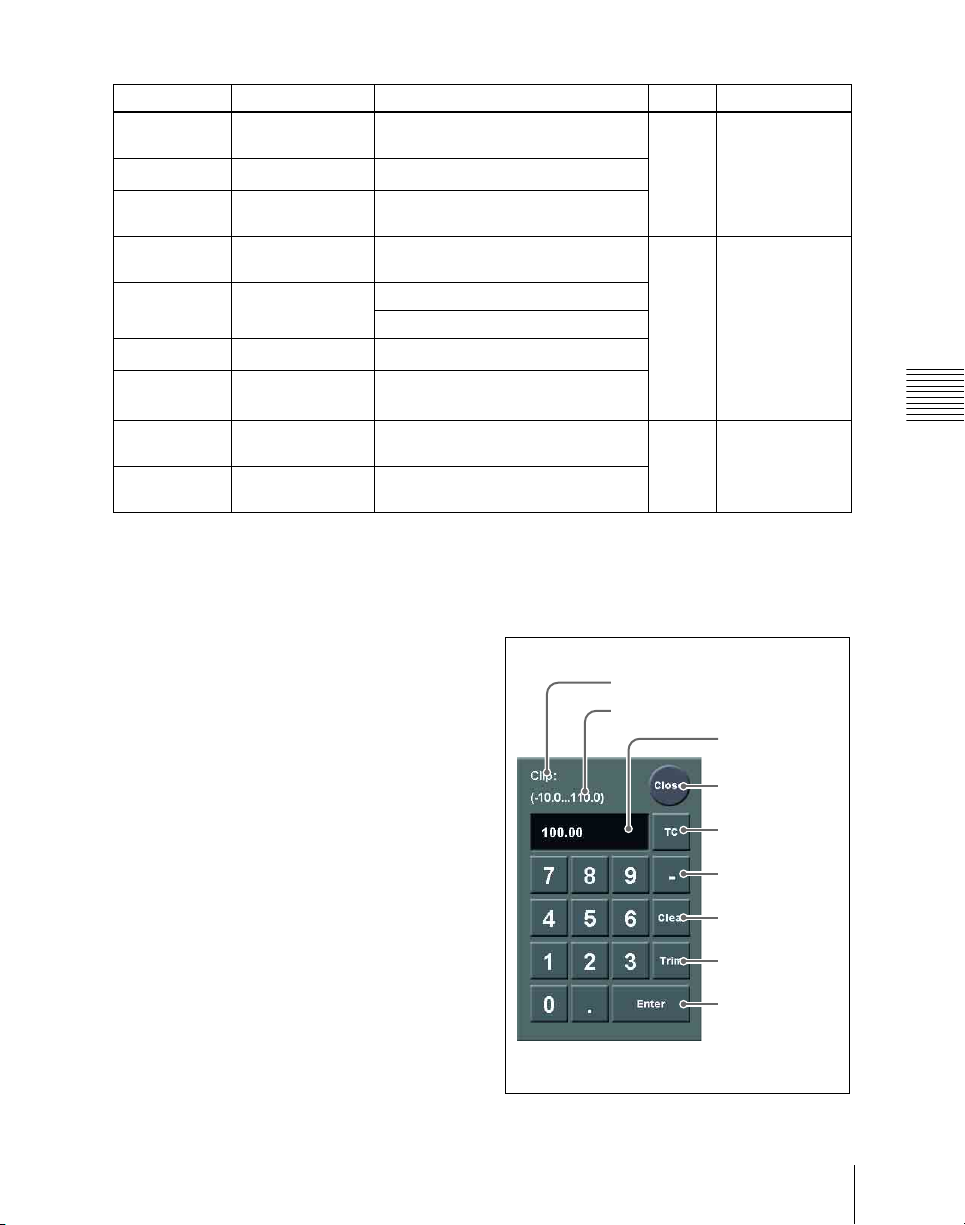
Knob parameters subject to restriction on default recall
Menu number Menu name Button name Knob Parameter
a)
1154.1
a)
1155
a)
1155.1
2122.2 Composite
Edge Direction
[Position] 1
>Matte Adjust
Main Modify [Position] in the <Position> group
Main Modify
[Position]
>Multi Adjust
[Position] 1
>Pattern Adjust
2
Position V
Position H
Position H
2
Position V
2131 Reposition [Normal]
[Black&White]
2210
2412.1
b)
Color Bkgd1
Primary CCR
>Mask1 Adjust
4116 DME >Edge
[Position]
[Position]
c)
[Position/Size] 5 Pattern
>Wipe Crop
4127 DME >Video
[Position/Size]
Modify >Mask
a) The menu numbers shown by way of example are those for M/E-1: the same applies to M/E-2,
M/E-3, and P/P. Equally, content applying to Key1 applies equally to Key2, Key3, and Key4.
b) The menu numbers shown by way of example are those for CCR1: the same applies to CCR2.
c) The sample applies to Mask2 Adjust.
Chapter 2 Menus and Control Panel
Numeric keypad window
1 Item display
2 Max./min. value indication
3 Input value
4 Close button
5 TC (timecode)
button
6 – (minus)
button
7 Clear button
8 Trim button
9 Enter button
83Basic Menu Operations
Page 84

a Item display
This is the name of the parameter being set
in the numeric keypad window.
b Max./min. (maximum/minimum)
value indication
This shows the maximum and minimum
settings of the parameter.
c Input value
This is the value being input into the
numeric keypad window.
d Close button
This closes the numeric keypad window.
If correctly set, the numeric keypad
window closes.
If not correctly set, the input display
changes color.
Chapter 2 Menus and Control Panel
e TC (timecode) button
When the numeric keypad window is
opened for a setting requiring a timecode
value to be entered, this button appears in a
depressed state.
You can enter a timecode value in the range
that depends on the signal format (see
“Setting the Signal Format (Format
Menu)” in Chapter 18 (Volume 3)) as
follows:
00:00:00:00 to 23:59:59:nn,
where nn = (number of frames per
second) – 1.
f – (minus) button
This toggles the sign of the entered value.
When it is pressed, the value is negative.
g Clear button
This clears the input. It does not change the
parameter setting.
h Trim button
After entering the difference from the
current value, press this button to confirm
the numeric input.
i Enter button
This confirms the entered value.
Basic Menu Operations
84
Page 85
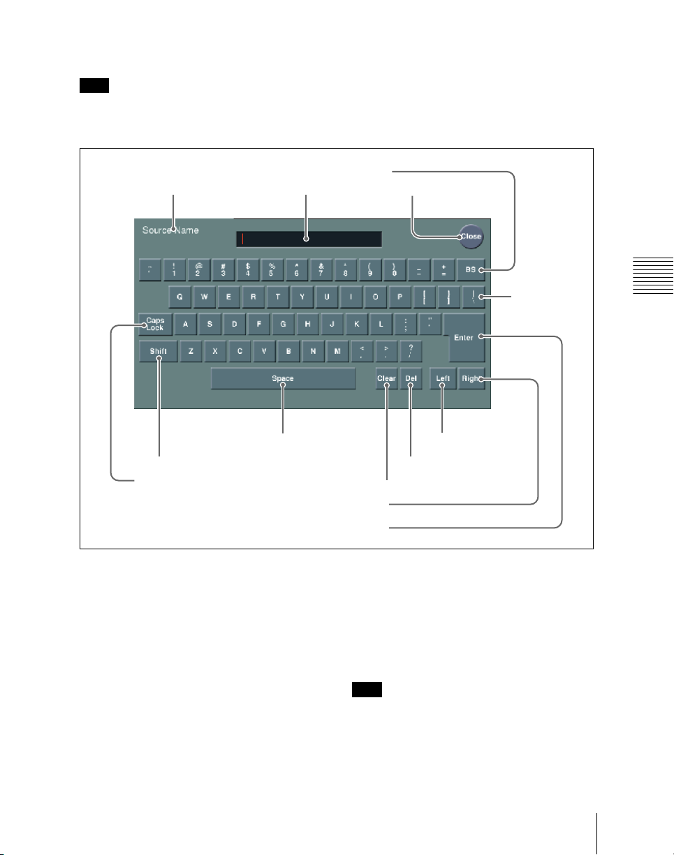
Keyboard window
Note
Except when changing source names, the
following characters cannot be used. The
same applies to macro file editing.
1 Item display 2 Input string
7 Space button
6 Shift button
5 Caps Lock button
space, \, /, :, ;, , (comma), . (dot), <, >,
*, ?, ", |
4 BS button
qa Right button
qs Enter button
3 Close button
0 Left button
9 Del button
8 Clear button
qd Line feed
button
Chapter 2 Menus and Control Panel
a Item display
This is the name of the parameter being set
in the keyboard window.
b Input string
This is the character string being input in
the keyboard window.
c Close button
This closes the keyboard window.
d BS button
This clears the character immediately
before the cursor in the input string.
e Caps Lock button
This enables input of capital letters only.
Note
You can enter items to be displayed on the
control panel LCD using lowercase letters,
but these will be converted to capitals for
display.
85Basic Menu Operations
Page 86
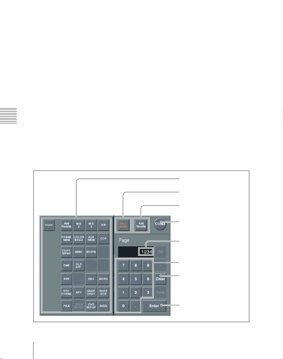
MS-DOS does not distinguish case in
filenames, and therefore you are
recommended to enter filenames in capital
j Left button
This moves the cursor one character to the
left in the input string.
letters.
k Right button
f Shift button
This selects the characters on the shift side
This moves the cursor one character to the
right in the input string.
of the keys. The shift is released when you
enter a character.
l Enter button
This sets the input string as a parameter
g Space button
This enters a space character.
value, and closes the keyboard window if
the value has been entered correctly. If the
value has not been entered correctly, the
h Clear button
display color changes.
This clears all of the characters in the input
Chapter 2 Menus and Control Panel
string.
i Del button
This clears the character immediately after
m Line feed button
After pressing the Shift button, press this
button to feed a line. The input string shows
|”.
“
the cursor in the input string.
Function of the top menu window
1 Top menu selection buttons
Basic Menu Operations
86
7 Shut down button
8 Add Favorite button
6 Close button
2 Input display
3 Numeric entry section
4 Clear button
5 Enter button
Page 87

a Top menu selection buttons
These are the same as the top menu
selection buttons in the menu control block.
Pressing one of these buttons closes the top
menu window and displays the selected
menu in the menu display.
b Input display
This shows the page number entered with
the numeric entry section.
c Numeric entry section
Enter a page number.
d Clear button
Press this to clear the input display.
e Enter button
Pressing this button without entering a page
number closes the top menu window with
the current menu remaining in the menu
display.
If you enter a page number then press this
button, this confirms the value in the input
display. If it is a correct page number, the
top menu window closes, and the menu
display shows the new menu. If it is not
correctly set, the input display changes
color.
f Close button
Press this to close the top menu window.
g Shut down button
Shuts down the menus.
Note
Be sure to shut down the menus before
powering off the control panel.
Shutting down the menus
1
In the menu screen, press the menu
page number button to open the top
menu window.
For details of the top menu window, see
“Function of the top menu window”
(page 86).
2
Press [Shut down].
A confirmation message appears.
3
Press [Yes].
This shuts down the menu system after
a while, and the menu display changes
to black. Now power off the system.
To restart menu operations
Power on the control panel once more.
h Add Favorite button
Pressing this button allows the currently
displayed menu to be registered to the
Shortcut menu.
Registering a menu to the
Shortcut menu
1
In the Home >Favorites >Shortcut
menu, select the desired group.
2
Display the menu you want to register,
and then press the [Add Favorite]
button.
The currently displayed menu is
automatically registered to a blank
button.
Chapter 2 Menus and Control Panel
Use of the color palette window
When a parameter is assigned to the knobs
as a combination of luminance, saturation,
and hue, pressing a knob parameter button
displays a color palette window.
87Basic Menu Operations
Page 88
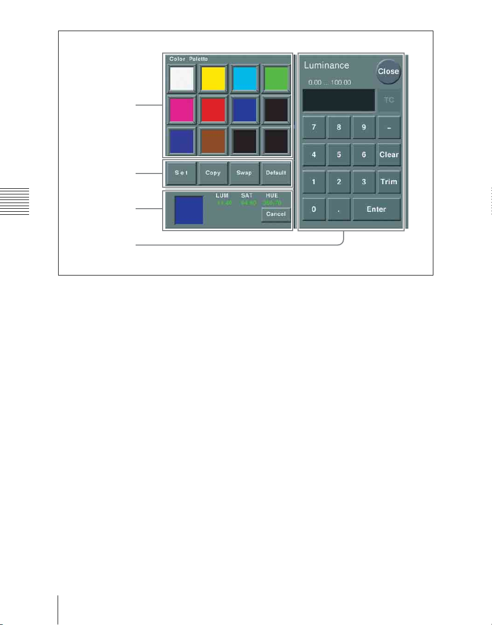
1Color palette
buttons
2Operation
buttons
Chapter 2 Menus and Control Panel
3Color display
4Numeric
keypad
a Color palette buttons
Press one of these to enter the
corresponding color in the display.
By default the following settings are
Default: If you press any color palette
button with this button held down, the
color palette button is set to the default
color.
available.
First row: white, yellow, cyan, green
Second row: magenta, red, blue, black
Third row: all black
c Color display
This shows the setting color, and the
parameters (LUM, SAT, and HUE).
By adjusting the parameters with the knobs,
b Operation buttons
Set: If you press any color palette button
with this button held down, the color
shown in the color display is assigned
to the color palette button.
Copy: If you press a color palette button
with this button held down, the color is
used as the source for copying. Next
you can create any color.
If a parameter value is outside the permitted
range for RGB (0 to 255), the indication
“Illegal Color” appears, and this is adjusted
to a value in range.
Cancel: Pressing this button returns to the
state when the color palette window
was opened.
press a different color palette button to
copy to that button.
Swap: If you press two color palette
buttons in sequence with this button
held down, the two colors are swapped.
d Numeric keypad
Use this to enter numeric values for
parameters.
For details of use, see page 83.
Basic Menu Operations
88
Page 89
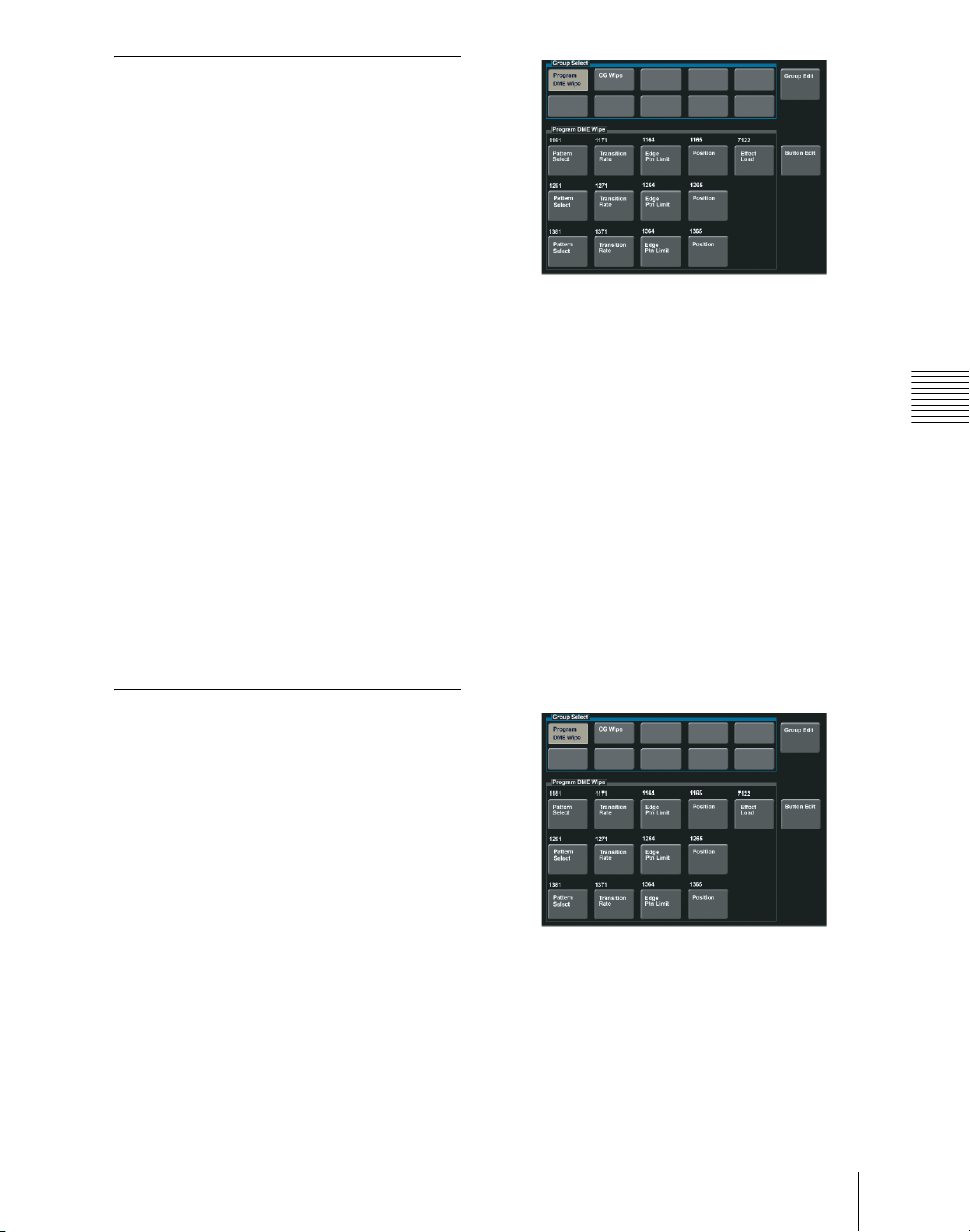
Switching Between the Main Menu Site and Subsidiary Menu Site
For menu transitions, you can store two
separate versions in the main and subsidiary
menu sites.
By switching sites, and pressing the b
button and the B button you can trace the
history in each menu.
2
In the [Group Select] box, select the
group.
To switch the subsidiary menu
site on and off
Assign [SUB MENU SITE] to a menu
control block top menu selection button or
user preference button. To switch to the
subsidiary menu site, press this button,
turning it on.
For details of the assignment operation, see
“Assigning Functions to the Menu Control
Block Top Menu and User Preference
buttons” in Chapter 19 (Volume 3).
Shortcut Menu
Recalling a menu using the
shortcut menu
1
In the Home menu, select VF2
‘Favorites’ and HF1 ‘Shortcut.’
The following menu appears.
The group buttons appear.
3
Press the button for the desired menu.
Creating a shortcut menu
Assign frequently used menus to buttons, to
create a “Favorites” menu.
To create a menu group
1
In the Home menu, select VF2
‘Favorites’ and HF1 ‘Shortcut.’
The following menu appears.
Chapter 2 Menus and Control Panel
2
Press [Group Edit].
The following menu appears.
89Basic Menu Operations
Page 90
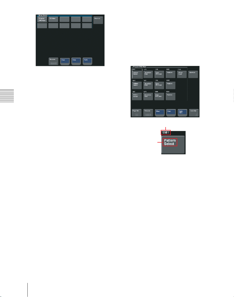
3
Press [Yes].
This deletes the settings.
To register a menu on a button
You can register 15 buttons in one group.
1
In the Home >Favorites >Shortcut
menu, press [Button Edit].
3
With the cursor, select the group name
(in this case a blank button) for the
operation.
4
Press [Rename].
Chapter 2 Menus and Control Panel
A keyboard window appears.
5
Enter a group name (maximum 24
characters), and press Enter.
This confirms the group name.
Menu No.
To copy a menu group
1
In the Home >Favorites >Group Edit
menu, press the button for the copy
source group.
2
Press [Copy].
3
Press the button for the copy
destination group.
4
Press [Paste].
This copies the menu group settings.
To delete menu group settings
1
In the Home >Favorites >Group Edit
menu, select the group to be deleted.
2
Press [Clear].
A confirmation message appears.
Button name
2
Move the cursor to the position where
you want to display the button. To
change the content of an already
displayed button, press the button to
select it.
3
Press [Page Set].
A page number input window appears.
4
Enter the page number for the menu
you want to register.
5
Press [Rename].
A keyboard window appears.
6
Enter the button name (maximum 24
characters).
Basic Menu Operations
90
Page 91

7
To change the button color, press
[Color Set].
Button color samples appear.
8
Press the desired color.
This completes the assignment of the
menu to the button.
9
Repeat steps 2 to 8 to complete the
“Favorites” menu.
To copy button settings
1
In the Home >Favorites >Button Edit
menu, press the copy source button to
select it.
2
Press [Copy].
3
Press the copy destination button to
select it.
4
Press [Paste].
This copies the button settings.
Chapter 2 Menus and Control Panel
To delete button settings
In the Home >Favorites >Button Edit
menu, press [Clear].
This deletes the button settings.
Note
The shortcut menu settings are handled as
part of the control panel setup. You can
recall and save them in the same way as
setup data.
91Basic Menu Operations
Page 92

Chapter 2 Menus and Control Panel
Basic Menu Operations
92
Page 93

Chapter 3 Signal Selection and Transitions
Video Processing Flow ...............................................................................94
Signal Selection ...........................................................................................96
Basics of Signal Selection ...................................................................96
Bus Selection .......................................................................................97
Signal Assignment and Selection ........................................................98
Signal Name Display .........................................................................102
Transitions .................................................................................................103
Selecting the Next Transition ............................................................103
Transition Types ................................................................................103
Procedure for Basic Transition Operation .............................................106
Key Priority Setting ..................................................................................109
Setting the Key Priority in the Transition Control Block ..................109
Setting the Key Priority by a Menu Operation ..................................111
Display of the Key Output Status and Key Priority ..........................113
Selecting the Transition Type by a Menu Operation ............................114
Super Mix Settings ...................................................................................115
Color Matte Settings .................................................................................116
Executing a Transition .............................................................................119
Transition Indicator Function ............................................................119
Setting the Transition Rate ................................................................120
Pattern Limit ......................................................................................122
Executing an Auto Transition ............................................................126
Executing a Transition With the Fader Lever (Manual Transition) ..127
Combinations of Auto and Manual Transitions ................................127
Non-Sync State ..................................................................................127
Fader Lever Operation in Bus Fixed Mode .......................................128
Transition Preview ...................................................................................131
Independent Key Transitions ..................................................................133
Basic Independent Key Transition Operations ..................................136
Setting the Independent Key Transition Type by a Menu Operation 136
Setting the Independent Key Transition Rate ....................................137
Page 94

Video Processing Flow
The switch from the current video stream (appearing on the corresponding
program monitor) to a new video stream is referred to as a transition.
The following illustration shows the flow of operations for carrying out a
transition on an M/E bank or the PGM/PST bank.
Chapter 3 Signal Selection and Transitions
Video Processing Flow
94
Page 95
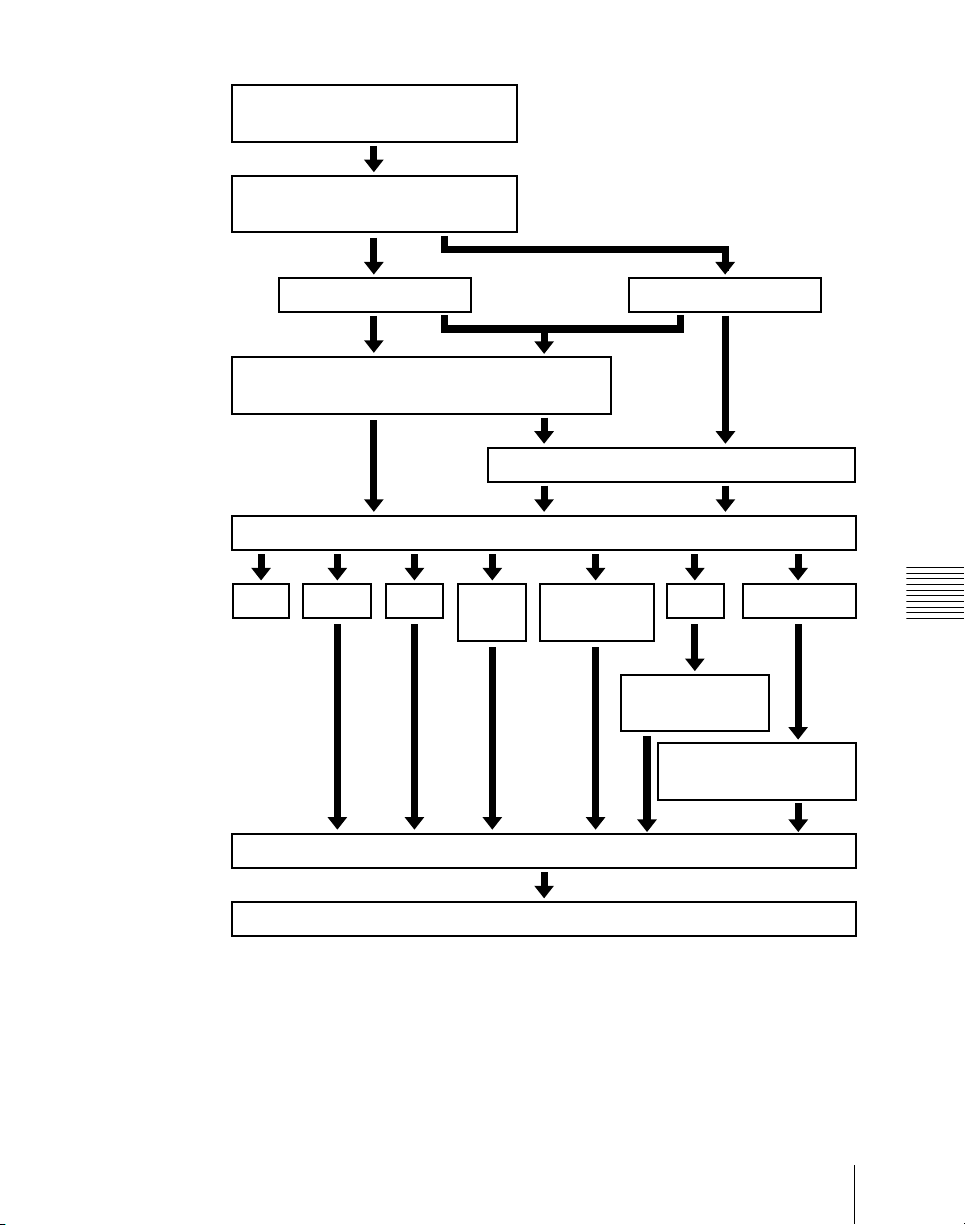
Select current background video
(page 96)
Select next transition (page 103)
Background
Select new background video (page 96)
Select transition type (page 103)
Cut Mix
NAM
Preview the effect of transition (page 131)
Super
mix
Keys 1 to 4
Make key settings (page 139)
Preset color
mix
Wipe
Make wipe settings
(page 201)
Make DME wipe settings
(page 232)
DME wipe
Chapter 3 Signal Selection and Transitions
Execute the transition (page 119)
95Video Processing Flow
Page 96
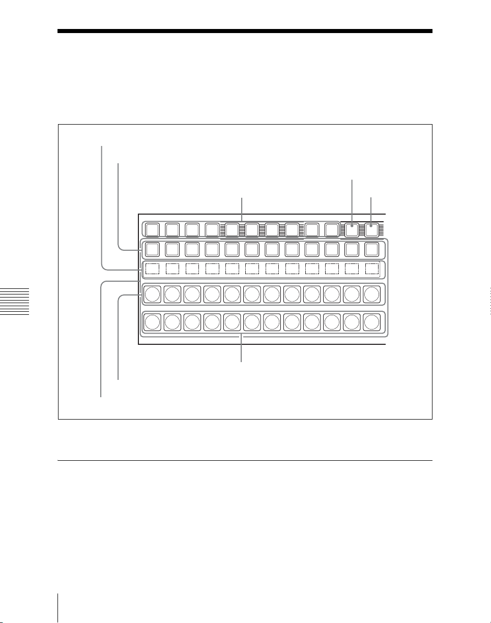
Signal Selection
You carry out signal selection with the cross-point buttons in the cross-point
control block of the M/E bank or PGM/PST bank, and the buttons in the
auxiliary bus control block.
Source name displays
Key row
XPT HOLD button
Key delegation buttons
Chapter 3 Signal Selection and Transitions
Background B row
Background A row
Cross-point buttons
Cross-point control block
SHIFT button
XPT
SHIFTUTIL2UTIL1DME4DME3DME2DME1DSK4DSK3DSK2DSK1
HOLD
Basics of Signal Selection
96
Each of the M/E bank and auxiliary bus control block has cross-point buttons
which are identified by numbers common to the bank and block, and a signal
is assigned to each number.
These buttons are identified by numbers common to all of the banks and block,
and a signal is assigned to each number.
Signal Selection
Page 97
The basis of signal selection is to select, in a cross-point button row, the crosspoint button to which is assigned the desired signal.
Bus Selection
The key row is shared by multiple buses.
To assign a bus to the cross-point buttons in the auxiliary bus control block,
press one of the AUX delegation buttons to select the bus.
Note
When using the CCP-6224/6324, buses may be assigned with the cross-point
button rows for keys 1 and 2 as the auxiliary bus control block.
The following table illustrates the correspondence between buses and crosspoint button rows, and the delegation operations.
Bank Bus name Cross-point
M/E-1 Background A bus Background A
Background B bus Background B
Key 1 bus Key row Turn on the [KEY1] button
Key 2 bus Turn on the [KEY2] button
Key 3 bus Turn on the [KEY3] button
Key 4 bus Turn on the [KEY4] button
PGM/PST Program bus Program row −
Preset bus Preset row −
DSK 1 bus DSK row Turn on the [DSK1] button
DSK 2 bus Turn on the [DSK2] button
DSK 3 bus Turn on the [DSK3] button
DSK 4 bus Turn on the [DSK4] button
M/E-1 PGM/
PST
Utility bus Key row Turn on the [UTIL] button
DME 1 video bus Turn on the [DME1] button
DME 2 video bus Turn on the [DME2] button
button row
row
row
Delegation operation
−
−
Chapter 3 Signal Selection and Transitions
a)
a)
97Signal Selection
Page 98
Bank Bus name Cross-point
Auxiliary
bus control
block
Chapter 3 Signal Selection and Transitions
AUX1 t o AUX48
buses
MONITOR 1 to
MONITOR 8 buses
Frame memory
source 1 and frame
memory source 2
buses
DME 1 and DME 2
video buses
DME 1 and DME 2
key buses
Edit preview bus
M/E-1 UTILITY bus
P/P UTILITY 1 and P/
P UTILITY 2 buses
M/E-1 Key 1 fill to M/
E-1 Key 4 fill buses
M/E-1 Key 1 source to
M/E-1 Key 4 source
buses
DSK 1 fill to DSK 4 fill
buses
DSK 1 source to DSK
4 source buses
M/E-1 external DME
bus
P/P external DME bus
button row
The key row of
the bank selected
with the bank
selection buttons
in the auxiliary
bus control block
Delegation operation
Turn on the appropriate
buttons in accordance with
the signal assignment made
in the Setup menu.
a) To turn on the [DME1] to [DME4] buttons requires one of the [KEY1] to [KEY4] and [DSK1]
to [DKS4] buttons to be on.
Signal Assignment and Selection
Assigning signals to buttons
Each cross-point button has a button number, to which you assign a signal.
In addition to the signals input to the PRIMARY INPUTS 1 to 49 connectors
on the rear panel of the switcher, you can also select signals generated within
the switcher.
Each button has assigned to it a video signal and a key signal, forming a pair.
You can set these video and key combinations in a Setup menu.
Signal Selection
98
Page 99

For details of Setup menu operations, see “Cross-Point Settings (Xpt Assign
Menu)” in Chapter 19 (Volume 3).
Cross-point button control block button numbers
On the M/E and PGM/PST banks, each cross-point button has two button
numbers, and you use the [SHIFT] button to switch between these numbers.
The button numbers are as follows.
Chapter 3 Signal Selection and Transitions
99Signal Selection
Page 100
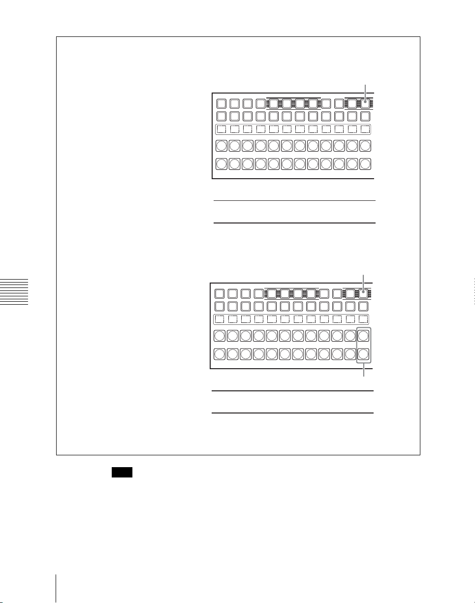
Button numbers when all 12 buttons are used as cross-point buttons.
UTIL1DME4DME3DME2DME1KEY4KEY3KEY2KEY1
SHIFT button
XPT
UTIL2
HOLD
SHIFT
When the SHIFT button is off:
When the SHIFT button is on:
123456789101112
13 14 15 16 17 18 19 20 21 22 23 24
Button numbers when the rightmost buttons (12th buttons) are used as SHIFT buttons.
SHIFT button
XPT
SHIFTUTIL2UTIL1DME4DME3DME2DME1KEY4KEY3KEY2KEY1
HOLD
Chapter 3 Signal Selection and Transitions
SHIFT buttons
When the SHIFT button is off:
When the SHIFT button is on:
1234567891011
12 13 14 15 16 17 18 19 20 21 22
Note
You can use the rightmost button (number 12) as a [SIDE FLAG] button. In
this case, the shift button moves one to the left, to number 11, and the button
numbers are offset by one.
100
For details of the [SIDE FLAG] button, see “Cross-Point Settings (Xpt Assign
menu)” in Chapter 16 (Volume 2).
Signal Selection
 Loading...