

Page 1
MVC-FD97
SERVICE MANUAL
Level 2
Ver 1.1 2001. 06
This service manual contains information for Japanese model as well.
When the machine needs to be repaired,
please refer to page 6 to discriminate the
type of LCD.
On the FC-85 board
This service manual procides the information that is premised the
circuit board replacement service and not intended repair inside the
FC-85 board.
Therefore, schematic diagram, printed wiring board and electrical
parts list of the FC-85 board is not shown.
The following pages are not shown.
US Model
Canadian Model
AEP Model
UK Model
E Model
Hong K ong Model
Australian Model
Korea Model
Japanese Model
FC-85 board
Schematic diagram.....................................Page 4-15 to 4-38
Printed wiring board ...................................Page 4-11 to 4-14
Electrical parts list ......................................Page 6-11 to 6-18
The above-described information is shown in service manual
Level 3.
System
Image device
6.64 mm (1/2.7 type) color
CCD
Lens
×
10 zoom lens
f = 6.0 – 60.0 mm (1/4 –
2 3/8inches)
(39 – 390 mm
(1 9/16 – 15 3/8 inches)
when converted into a
35 mm still camera)
F = 2.8
Exposure control
Automatic exposure
White balance
Automatic, Indoor, Outdoor,
One-push
Data system
Movie: MPEG
Still: JPEG, GIF (in TEXT
mode, Clip Motion), TIFF
Audio with still image:
MPEG (Monaural)
SPECIFICATIONS
Recording medium
Floppy disk:
3.5 inch 2HD MS-DOS
format (1.44 MB)
“Memory Stick”
Flash
Recommended recording
distance:
0.6mto2.5m(235/8inches
to 8 1/3 feet)
Input and Output
connector
A/V OUT (MONO)
(Monaural)
Minijack Video:
1 Vp-p, 75 Ω,unbalanced,
sync negative
Audio: 327 mV (at a 47 kΩ
load)
Output impedance: 2.2 kΩ
ACC jack
Minijack
USB jack
mini-B
LCD screen
LCD panel
TFT (Thin Film Transistor
activematrix) drive
Total number of dots
123 200 (560×220) dots
Finder
LCD panel
TFT (Thin Film Transistor
activematrix) drive
Total number of dots
180 000 (800×225) dots
– Continued on next page –
DIGITAL STILL CAMERA
Page 2

General
Application
Sony battery pack NP-F330
(supplied)/F550
Power requirements
8.4 V
Power consumption
(During shooting)
4.2 W (When using the LCD
screen)
3.8 W (When using the
finder)
Operating temperature
0°Cto40°C(32°Fto104°F)
Storage temperature
–20°Cto+60°C(–4°Fto
+140°F)
Dimensions (Approx.)
127×124×184 mm
(5×5×7 1/4 inches) (w/h/d)
Mass (Approx.)
990g(2lb3oz)(including
NP-F330 battery pack,
floppy disk/“Memory Stick”
and lens cap, etc.)
Built-in microphone
Electret condenser
microphone
Built-in speaker
Dynamic speaker
AC-L10A/L10B/L10C
AC power adaptor
Power requirements
100 to 240 V AC, 50/60 Hz
Rated output voltage
DC 8.4 V, 1.5 A in operating
mode
Operating temperature
0°Cto40°C(32°Fto104°F)
Storage temperature
–20°Cto+60°C(–4°Fto
+140°F)
Dimensions (Approx.)
125×39×62 mm (5×19/16×
2 1/2 inches) (w/h/d)
Mass (Approx.)
280 g (10 oz)
NP-F330 battery pack
Battery type
Lithium ion
Maximum output
voltage
DC 8.4 V
Mean output voltage
DC 7.2 V
Capacity
5.0 Wh (700 mAh)
Operating temperature
0°Cto40°C(32°Fto104°F)
Dimensions (Approx.)
38.4×20.6×70.8 mm
(1 9/16×13/16×2 7/8 inches)
(w/h/d)
Mass (Approx.)
70 g (2 oz)
Accessories
AC-L10A/L10B/L10C
AC power adaptor (1)
Power cord (mains lead) (1)
USB cable (1)
NP-F330 battery pack (1)
A/V connecting cable (1)
Shoulder strap (1)
Lens cap (1)
Lens cap strap (1)
CD-ROM (SPVD-004 USB
Driver) (1)
Operating instructions (1)
Design and specifications
are subject to change
without notice.
• Floppy disk that can be used by the MVC-FD97
• Size : 3.5-inch
• T ype : 2 HD
• Capacity : 1.44 MB
• Format : MS-DOS format
(512 bytes × 18 sector)
(FD can be formatted by the MVC-FD97)
SAFETY-RELATED COMPONENT WARNING!!
COMPONENTS IDENTIFIED BY MARK 0 OR DOTTED
LINE WITH MARK 0 ON THE SCHEMA TIC DIAGRAMS
AND IN THE PARTS LIST ARE CRITICAL TO SAFE
OPERATION. REPLACE THESE COMPONENTS WITH
SONY PARTS WHOSE PART NUMBERS APPEAR AS
SHOWN IN THIS MANUAL OR IN SUPPLEMENTS PUBLISHED BY SONY.
SAFETY CHECK-OUT
After correcting the original service problem, perform the following
safety checks before releasing the set to the customer.
ATTENTION AU COMPOSANT AYANT RAPPORT
À LA SÉCURITÉ!
LES COMPOSANTS IDENTIFIÉS P AR UNE MARQUE 0
SUR LES DIAGRAMMES SCHÉMATIQUES ET LA LISTE
DES PIÈCES SONT CRITIQUES POUR LA SÉCURITÉ
DE FONCTIONNEMENT. NE REMPLACER CES COMPOSANTS QUE PAR DES PIÈCES SONY DONT LES
NUMÉROS SONT DONNÉS DANS CE MANUEL OU
DANS LES SUPPLÉMENTS PUBLIÉS PAR SONY.
1. Check the area of your repair for unsoldered or poorly-soldered connections. Check the entire board surface for solder
splashes and bridges.
2. Check the interboard wiring to ensure that no wires are
“pinched” or contact high-wattage resistors.
3. Look for unauthorized replacement parts, particularly transistors, that were installed during a previous repair. Point them
out to the customer and recommend their replacement.
4. Look for parts which, though functioning, show obvious signs
of deterioration. Point them out to the customer and recommend their replacement.
5. Check the B+ voltage to see it is at the values specified.
6. Flexible Circuit Board Repairing
• Keep the temperature of the soldering iron around 270 ˚C
during repairing.
• Do not touch the soldering iron on the same conductor of
the circuit board (within 3 times).
• Be careful not to apply force on the conductor when sol-
dering or unsoldering.
– 2 –
Page 3

TABLE OF CONTENTS
Section Title Page Section Title Page
SERVICE NOTE................................................................... 5
Self-diagnosis Display ............................................................. 7
1. GENERAL
Introduction.............................................................................. 1-1
Identifying the Parts................................................................. 1-2
Preparing the Power Supply ................................................... 1-2
Setting the Date and Time ....................................................... 1-3
Inserting a Floppy Disk............................................................ 1-4
Inserting a “Memory Stick” ..................................................... 1-4
Recording Still Images ............................................................ 1-4
Recording Moving Images ...................................................... 1-6
Playing Back Still Images........................................................ 1-6
Playing Back Moving Images .................................................. 1-7
Viewing Images Using a Computer......................................... 1-7
Image File Storage Destinations and Image File Names....... 1-9
Before Perfor ming Advanced Operations ............................... 1-10
Various Recording ................................................................... 1-12
Various Playback..................................................................... 1-15
Editing ..................................................................................... 1-16
As an External Drive................................................................ 1-18
Additional Information ............................................................. 1-18
Troubleshooting ....................................................................... 1-20
Warning and Notice Messages ............................................... 1-21
Self-diagnosis Display ............................................................. 1-22
LCD Screen Indicators ............................................................ 1-22
2. DISASSEMBLY
2-1. Top Cabinet Block Assembly......................................... 2-2
2-2. EVF Block Assembly ..................................................... 2-2
2-3. VF Lens Assembly ........................................................ 2-2
2-4. VF-143 Board ................................................................ 2-2
2-5. Cabinet (Rear) Block Assembly .................................... 2-3
2-6. PK-55 Board .................................................................. 2-3
2-7. LCD Module................................................................... 2-4
2-8. FDD Block Assembly..................................................... 2-5
2-9. FU-153 Board ................................................................ 2-5
2-10. Lens Complete Block Assembly ................................... 2-5
2-11. Cabinet VP Block Assembly.......................................... 2-5
2-12. VP-55 Board .................................................................. 2-6
2-13. Lens Block Assembly .................................................... 2-6
2-14. FC-85 Board .................................................................. 2-7
2-15. CF-83 Board .................................................................. 2-7
2-16. Circuit Boards Location ................................................. 2-8
2-17. Flexible Boards Location............................................... 2-9
3. BLOCK DIAGRAMS
3-1. Overall Block Diagram ................................................ 3-1
3-12. Power Block Diagram 1............................................... 3-23
3-13. Power Block Diagram 2............................................... 3-25
3-14. Power Block Diagram 3............................................... 3-27
4. PRINTED WIRING BOARDS AND
SCHEMATIC DIAGRAMS
4-1. Frame Schematic Diagrams ......................................... 4-3
Frame Schematic Diagram (1/2)................................... 4-3
Frame Schematic Diagram (2/2)................................... 4-5
4-2. Printed Wiring Boards and Schematic Diagrams ......... 4-7
CD-311 Printed Wiring Board........................................ 4-7
CD-311 (CCD IMAGER) Schematic Diagram............... 4-8
CD-311 (STEADY SHOT SENSOR)
Schematic Diagram ....................................................... 4-9
VP-55 Printed Wiring Board......................................... 4-39
VP-55 Schematic Diagram........................................... 4-41
PK-55 Printed Wiring Board.......................................... 4-43
PK-55 (MODE SWITCH, A/V OUT)
Schematic Diagram ....................................................... 4-47
PK-55 (LCD DRIVE) Schematic Diagram..................... 4-49
PK-55 (LCD TIMING GENERATOR)
Schematic Diagram ....................................................... 4-51
PK-55 (BACK LIGHT DRIVE) Schematic Diagram ...... 4-53
VF-143 Printed Wiring Board....................................... 4-55
VF-143 (LCD DRIVE) Schematic Diagram................... 4-57
VF-143 (TIMING GENERATOR, EVF LCD,
BACK LIGHT) Schematic Diagram............................... 4-59
MA-404 Printed Wiring Board and
Schematic Diagram ....................................................... 4-61
AE-25 Printed Wiring Board and
Schematic Diagram ....................................................... 4-63
CF-83 Printed Wiring Board and
Schematic Diagram ....................................................... 4-65
FU-153 Printed Wiring Board and
Schematic Diagram ....................................................... 4-67
4-3. Waveforms .................................................................... 4-69
4-4. Parts Location ............................................................... 4-73
5. ADJUSTMENTS
Before Starting Adjustment ..................................................... 5-1
1-1. Adjusting Items when Replacing
Main Parts and Boards.................................................. 5-2
5-1. Camera Section Adjustments........................................ 5-3
1-1. Preparations Before Adjustment ................................... 5-3
1-1-1. List of Service Tools ................................................. 5-3
1-1-2. Preparations ............................................................. 5-4
1-1-3. Discharging of the Flashlight Power Supply............ 5-4
1-1-4. Precautions .............................................................. 5-6
1. Setting the Switch .................................................... 5-6
2. Order of Adjustments ............................................... 5-6
3. Subjects.................................................................... 5-6
4. Preparing the Flash Adjustment Box ....................... 5-7
1-2. Initialization of B, D, E, F, 7 Page Data ........................ 5-8
1-2-1. Initialization of D Page Data .................................... 5-8
1. Initializing D Page Data............................................ 5-8
2. Modification of D Page Data .................................... 5-8
3. D Page Table ............................................................ 5-8
1-2-2. Initialization of B, E, F, 7 Page Data ........................ 5-9
1. Initializing B, E, F, 7 Page Data ............................... 5-9
2. Modification of B, E, F, 7 Page Data........................ 5-9
3. B Page Ta ble ............................................................ 5-9
4. E Page Ta ble ............................................................ 5-9
5. F Page Table ............................................................ 5-10
6. 7 Page Table ............................................................ 5-12
1-3. Video System Adjustments ........................................... 5-13
1. Video Sync Level Adjustment ....................................... 5-13
2. Video Burst Level Adjustment....................................... 5-13
1-4. Camera System Adjustment ......................................... 5-14
1. Hall Adjustment ............................................................. 5-15
2. Flange Back Adjustment (Using the Minipattern Box).. 5-16
3. Flange Back Adjustment (Using the Flange Back
Adjustment Chart and a Subject More than
500 m Away).................................................................. 5-17
4. Flange Back Check ....................................................... 5-18
5. F No. Standard Data Input ............................................ 5-19
6. Mechanical Shutter Adjustment .................................... 5-19
7. Picture Frame Setting ................................................... 5-20
8. Light Level Adjustment and ND Shutter Check ............ 5-21
9. Mixed Color Cancel Adjustment.................................... 5-22
10. Auto White Balance Standard Data Input..................... 5-22
11. Auto White Balance ND Filter Compensation .............. 5-23
12. Auto White Balance Adjustment ................................... 5-24
13. Color Reproduction Adjustment .................................... 5-25
14. Color Reproduction Check............................................ 5-26
15. Auto White Balance Check ........................................... 5-28
16. Strobe White Balance Adjustment ................................ 5-30
17. Strobe Light Level and White Balance Check.............. 5-31
18. CCD Black Defect Compensation................................. 5-32
– 3 –
Page 4

Section Title Page
19. CCD White Defect Compensation ................................ 5-33
20. Steady Shot Adjustment................................................ 5-34
1-5. Color Electronic Viewfinder System Adjustments ........ 5-37
1. EVF Initial Data Input .................................................... 5-37
2. VCO Adjustment (VF-141 Board) ................................. 5-38
3. Bright Adjustment (VF-141 Board)................................ 5-39
4. Contrast Adjustment (VF-141 Board) ........................... 5-40
5. Backlight Consumption Current Adjustment
(VF-141 Board).............................................................. 5-41
6. White Balance Adjustment (VF-141 Board).................. 5-41
1-6. LCD System Adjustments ............................................. 5-42
1. LCD Initial Data Input .................................................... 5-43
2. VCO Adjustment (FC-85 Board) ................................... 5-44
3. D Range Adjustment (FC-85 Board)............................. 5-44
4. Bright Adjustment (FC-85 Board).................................. 5-45
5. Contrast Adjustment (FC-85 Board) ............................. 5-45
6. Color Adjustment (FC-85 Board) .................................. 5-46
7. V-COM Level Adjustment (FC-85 Board) ..................... 5-46
8. V-COM Adjustment (FC-85 Board) ............................... 5-47
9. White Balance Adjustment (FC-85 Board) ................... 5-47
1-7. System Control System Adjustments ........................... 5-48
1. Battery Down Adjustment.............................................. 5-48
2. ZOOM Center Adjustment............................................. 5-49
3. Eye Sensor Adjustment................................................. 5-49
4. Eye Sensor Check ........................................................ 5-50
5. Alignment Check (FDD Unit)......................................... 5-50
5-2. Service Mode ................................................................ 5-51
2-1. Adjusting Remote Commander ..................................... 5-51
1. Used the Adjusting Remote Commander ..................... 5-51
2. Precaution upon Using the Adjusting
Remote Commander ..................................................... 5-51
2-2. Data Process ................................................................. 5-52
2-3. Service Mode ................................................................ 5-53
1. Setting the Test Mode ................................................... 5-53
2. Bit Value Discrimination ................................................ 5-53
3. Switch Check (1) ........................................................... 5-53
4. Switch Check (2) ........................................................... 5-53
5. Switch Check (3) ........................................................... 5-54
6. LED Check .................................................................... 5-54
7. Self Diagnosis Code...................................................... 5-54
6. REPAIR PARTS LIST
6-1. Exploded Views ............................................................. 6-1
6-1-1. Main Section ............................................................. 6-1
6-1-2. Top Cabinet Block Assembly ................................... 6-2
6-1-3. EVF Block Assembly................................................ 6-3
6-1-4. Lens Complete Assembly ........................................ 6-4
6-1-5. Lens Block Assembly............................................... 6-5
6-1-6. Cabinet (Front) Block Assembly .............................. 6-6
6-1-7. FDD Block Assembly................................................ 6-7
6-1-8. Cabinet (Rear) Block Assembly............................... 6-8
6-2. Electrical Parts List........................................................ 6-9
* The color reproduction frame is shown on page 169.
– 4 –
Page 5
SERVICE NOTE
When installing a connector, don’t press down at wire of connector.
It is possible that a wire is snapped.
• NOTE FOR REPAIR
Make sure that the flat cable and flexible board are not cracked of
bent at the terminal.
Do not insert the cable insufficiently nor crookedly.
Cut and remove the part of gilt
which comes off at the point.
(Be careful or some pieces of
gilt may be left inside)
When remove a connector, don’t pull at wire of connector.
It is possible that a wire is snapped.
[Discharging of the FLASH unit’s charging capacitor]
The charging capacitor of the FLASH unit is charged up to the
maximum 300 V potential.
There is a danger of electric shock by this high voltage when the
battery is handled by hand. The electric shock is caused by the
charged voltage which is kept without discharging when the main
power of the MVC-FD97 is simply turned off. Therefore, the remaining voltage must be discharged as described below.
Preparing the Short Jig
T o preparing the short jig. a small clip is attached to each end of a
resistor of 1 kΩ /1 W (1-215-869-11).
Wrap insulating tape fully around the leads of the resistor to prevent electrical shock.
1 kΩ/1 W
Wrap insulating tape.
Discharging the Capacitor
Short-circuit between the positive and the negative terminals of
charged capacitor with the short jig about 10 seconds.
R: 1 kΩ/1 W
(Part code:
1-215-869-11)
Capacitor
– 5 –
Page 6
[LCD type check]
By measuring the resistor value between Pin qd of CN803 and Pin
4 of CN803 on FC-85 board, the type of LCD can be discrimi-
nated.
Note: About PK-55 board and LCD module, discriminate LCD
type on the machine, and replace the same type.
FC-85 board CN803
Resistor
value
LCD type PD board
4.7 kΩ TYPE S PK-55 (TYPE S)
47 kΩ TYPE C PK-55 (TYPE C)
Volt ohm meter
FC-85 board
CN803
22
1
CPC cover
qd pin
4 pin
1
22
CPC-12 jig
(J-6082-436-A)
– 6 –
Page 7

[Description on Self-diagnosis Display]
Note : The “Self-diagnosis” data is backed up by the coin lithiumbattery.
The data will be lost and initialized when the coin lithium battery
is removed.
Display Code
C:32:01
Change the disk and turn off the main
power then back on.
Countermeasure
Cause
Defective floppy disk.
• The type of floppy disk that cannot be
C:13:01
Replace the floppy disk or “Memory
Stick”.
Format the floppy disk or “Memory Stick”
with the MVC-FD97.
used by this machine, is inserted.
(Such as 2DD)
• Data is damaged.
• Unformatted disk or “Memory Stick”
is inserted.
E:91:01
Checking of flash unit or replacement of
flash unit
Abnormality when flash is being
charged.
E:61:00
E61:10
Checking of lens drive circuit
When failed in the focus initialization.
Note : The error code is cleared if the battery is removed, except defective flash, unit.
*1: When the flash charging failed, Page: D, Address: 67, Data: 04 are written.
After repair, be sure to write Page: D, Address: 67, Data: 00.
[Power supplying Method]
Use the AC power adaptor (AC-L10A) when supplying the power to this set.
Caution Display During Error
DRIVE ERROR
DISK ERROR
MEMORY STICK ERROR
Flash LED
Flash display
*1
Flashing at 3.2 Hz
—
– 7 –
Page 8
SECTION 1
GENERAL
MVC-FD97
This section is extracted
from instruction manual.
.
WARNING
To prevent fire or shock hazard, do
not expose the unit to rain or
moisture.
For the Customers in the
U.S.A.
This symbol is intended to
alert the user to the presence
of uninsulated “dangerous
voltage” within the
product’s enclosure that
may be of sufficien t
magnitude to constitute a
risk of electr ic shock to
persons.
This symbol is intended to
alert the user to the presence
of important operating and
maintenance (servicing)
instructions in the lite ratu re
accompanying the
appliance.
If you haveany questions about this product,
you may call:
Sony Customer Information Center
1-800-222-SONY (7669)
The number below is for the FCC related
matters only.
2
Regulatory Information
Declaration of Conformity
Trade Name: SONY
Model No.: MVC-FD97
Responsible Party:Sony Electroni cs Inc .
Address: 1 Sony Drive, Park
Telephone No.: 201-930-6972
This device complies with Par t 15 of the
FCC Rules. Operatio n is subject to the
following two conditions: (1) This device
may not cause harmful interference, and
(2) this device must accept any
interference received, including
interference that may cause undesired
operation.
CAUTION
You are cautioned that any changes or
modifications not expres sly approved
in this manual could void y our
authority to operate this equipment.
Note:
This equipment has been tested and found to
comply with the limi ts for a Class B digital
device, pursuant to Part 15 of the FCC
Rules. These limits are design ed to provide
reasonable protection against harmful
interference in a residential installation. This
equipment generates, uses, and can radiate
radio frequency energy and, if not installed
and used in accordance with the
instructions, maycause harmful interference
to radio communications. However, there is
no guarantee that interference will not occur
in a particular installation. I f this equipment
does cause harmful interference to r adio or
television reception,which can be
determined by turning thee quipmentoff and
on, the user is encouraged to try to correct
the interference by one or more of the
following measures:
— Reorient or relocate the receiving ante nna.
— Increase the separation between the
equipment and receiver.
— Connect the eq uipment into anou tleton
a circuit different from that to whic ht he
receiver is co nnected.
—C onsult the dealer or an experienced
radio/TV technician for hel p.
Ridge, NJ, 07656
USA
The supplied interface cable must be use d
with the equipment in order to comply with
the limits for a digita l dev ice pursuant to
Subpart B of Part 15 of FCC Rules.
For the Customers in the
U.S.A. and Canada
DISPOSAL OF LITHIUM ION
BATTERY.
LITHIUM ION BATTERY.
DISPOSE OF PROPERLY.
You can return your unwanted lithium ion
batteries to your nearest Sony Service
Center or Factory Service Center.
Note:
In some areas the disposal of lithium ion
batteries in household or business trash may
be prohibited.
For the Sony ServiceCenter nearest you call
1-800-222-SONY (United States onl y)
For the SonyFactory Service Center nearest
you call 416-499-SONY (Canada only)
Caution:
Do not handle damaged or leaking lithium
ion battery.
For the Customers in Canada
CAUTION
TO PREVENTELECTRIC SHOCK, DO NOT
USE THIS POLARIZED AC PLUG WITH
AN EXTENSION CORD, RECEPTACLE OR
OTHER OUTLET UNLESS THEBLADES
CAN BE FUL LY IN SERTED TO PREVENT
BLADE EXPOSURE .
NOTICE FOR THE
CUSTOMERS IN THE UNITED
KINGDOM
A moulded plug complying with BS 1363 is
fitted to this equipment for your safety and
convenience.
Should the fuse in the plug suppli ed ne ed to
be replaced, a 5 AMP fuse approved by
ASTA or BSI to BS 1362, (i.e. marked with
or mark) must be used.
If the plug supplied with th is equipment has
a detachable fuse cover, be sureto attach the
fuse cover after you change the fuse. Never
use the plug without the fuse cover. If you
should lose the fuse cover, please contact
your nearest Sony service station.
For the Customers in
Germany
Directive:EMC Directive 89/336/EEC.92/
31/EEC
This equipment complies with th e EMC
regulations when used under the fol lowing
circumstances:
• Residential area
• Business district
• Light-industry district
(This equipment complies with the EMC
standard regulations EN55022 Clas s B.)
Attention
The electromagnetic fields at the specific
frequencies may influence th e picture and
sound of this camera.
3
Be sure to read the following
before using your camera
Operating instructions
Before operating the u nit, please read this
manual thoroughly, and retain it for future
reference.
As you read through this manua l, bu ttons
and settings on the camera are shown in
capital letters.
e.g. Press DISPLAY.
Trial recording
Before you record one-time events, youmay
want to make a trial recordi ng to make sure
that the camera is working correctly.
No compensation for contents of
the recording
Contents of the recording cannot be
compensated for if recording or playback is
not made due to a malfunctio no f your
camera or recording medium, et c.
Notes on im age data com patibility
of the “Memory Stick”
• Thiscamera conforms withthe Design rule
for Camera File system universal stan dard
established by the JEITA (Japan Electrics
and Information Technology Industries
Association). You cannot play back on
your camera still images recorded on other
equipment (DCR-TRV890E/TRV900/
TRV900E, DSC-D700, DSC-D770) that
does not conform with this universal
standard. (These models ar e not sold in
some areas.)
• Playback of images recorded with your
camera on other equipment and playback
of images recorded or edited with other
equipment on your camera are not
guaranteed.
Precaution on copyright
Television programs, films, video tapes, and
other materials may be copyrighted.
Unauthorized recording ofs uch materials
may be contrary to the pr ovisio n of the
copyright laws.
4
Do not shake or strike the camera
In addition to malfunct ions and inability to
record images, this may ren der the floppy
disks or “Memory Stick”s unusable or
image data breakdown, damage or loss may
occur.
LCD screen, finder (only models
with a finder) and lens
• The LCD screen and the finder are
manufactured using extremely high precision technology so over 99.99% o f
the pixels are operational for effective use.
However, there may be some tiny black
points and/or bright points (wh ite, red,
blue or green in color) that consta ntly
appear on the LCD screen and the finder.
These points are normal in the
manufacturing process and do not affect
the recording in any way.
• Be careful when placing the camera near a
window or outdoors. Exposing the LCD
screen, the finder or the lens to direc t
sunlight for long periods may cause
malfunctions.
Do not get the camera wet
When taking pictures outdoors in the rain or
under similar conditions, be car eful n ot to
get the camera wet. If moisture
condensation occurs, refer to page 74 a nd
follow the instructions on how to remove it
before using the camera.
Back up recommendation
To avoid the potential risk of data loss,
always copy (back up) data to a disk.
When the camera is used for long
periods
Note that the camera body may b ecom e hot.
Introduction
Deletes undesired images right away, checking the image
after shooting
The digital still camera is able to play back the image and delete it right away.
Recording still images:
page 18
Playing back still images:
page 26
Deleting images
(DELETE): page 66
Captures images with your computer
You can easily copy images onto your computer using a floppy disk or a “Memory
Stick,” and view and modify images on your computer using application software.
Viewing images using a
computer: page 29
Records a moving picture with audio
The digital still camera can record a moving picture with audio for maximum 60 seconds.
Recording moving
images: page 25
Selects the recording mode from various types of recordings
according to your situation
Creating Clip Motion Files: page 49
Recording still images for e-mail (E-MAIL): page 51
Adding audio files to still images (VOICE): page 51
Recording text docum ents (TEXT): page 52
Recording still images as uncompressed files (TIFF): page 53
6
1-1
Page 9
Getting started
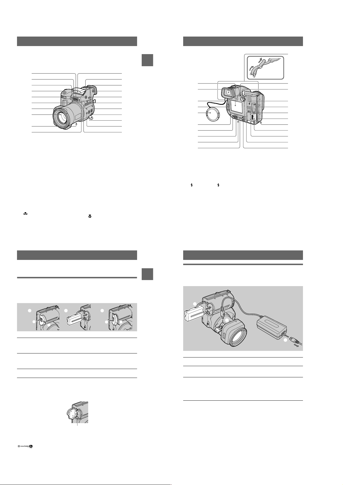
Identifying the parts
See the pages in par entheses for details o f operation.
1
2
3
4
5
6
7
8
9
0
OPEN (FLASH) button (23)
A
Built-in microphone
B
Do not touch while r ecording.
Self-timer lamp (23)
C
Shutter button (18, 25)
D
Zoom lever (21)
E
Photocell window for flash
F
Do not block while r ecording.
Focus ring (55)
G
Lens
H
DC IN cover/DC IN jack (10, 13)
I
(One-push white balance)
J
button (59)
K
L
M
N
O
P
Q
R
S
T
U
qa
qs
qd
qf
qg
qh
qj
qk
ql
w;
wa
Flash (23)
Accessory shoe
SPOT METER button (57)
Finder adjustment dial (19)
WHITE BALANCE button (59)
PROGRAM AE button (56)
STEADY SHOT ON/OFF switch
(22)
A/V OUT (MONO) jack (64)
Audio output is mo naural.
FOCUS AUTO/MANUAL switch
(54, 55)
(Macro) button (54)
PROGRAM AE +/– buttons (56)
qa
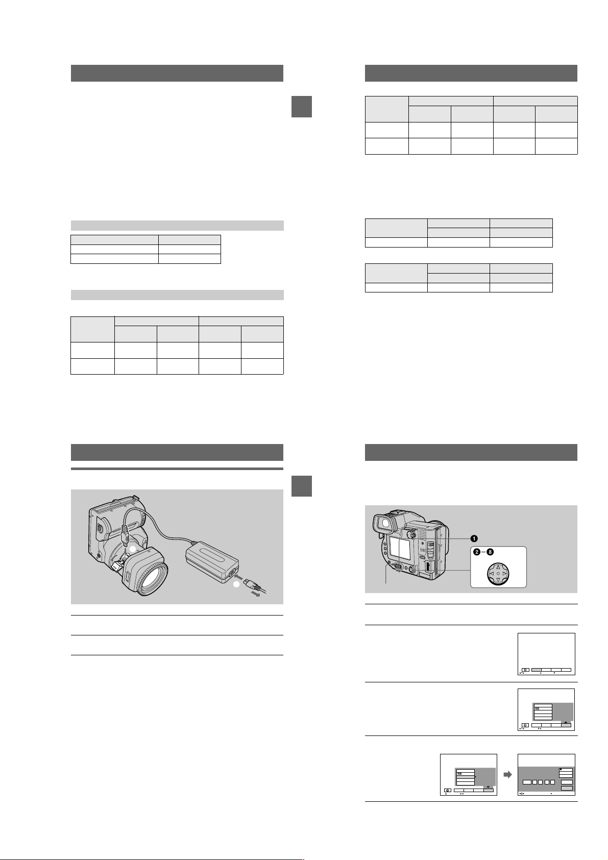
Getting started
1
2
3
4
5
Attaching the
shoulder strap
qs
qd
qf
qg
qh
qj
6
7
8
9
0
LCD screen
A
Finder (19)
B
LCD ON/OFF switch (20)
C
VOL +/– buttons (28)
D
Lens cap (supplied)
E
(Flash) button/ (Flash)
F
lamp (23)
POWER ON/OFF (CHG)
G
(Charge) lamp (11, 14)
POWER switch (14)
H
Tripodr eceptacle (bottom surface)
I
Useatripodwithascrewlengthof
less than 6.5 m m (7/32 inch). You
cannot firmly secure the camera to
tripods having longer sc rews, and
may damage the cam era.
DISPLAY button (22)
J
7
8
Hooks for strap
K
ACC (Accessory) jack
L
PLAY/STILL/MOVIE selector (40)
M
Access lamp (18, 19)
N
DISK EJECT lever (16)
O
Speaker
P
Floppy disk slot (16)
Q
Battery cover/PUSH button
R
(bottom surface) (9)
“Memory Stick” cover/
S
“Memory Stick” slot (17)
USB cover/USB jack (31)
T
MS /FD (“Memory Stick”/floppy
U
disk) selector
Control button (40)
V
qk
ql
w;
wa
ws
Preparing the power supply
Installing the battery pack
Your camera operates only with the NP-F 330 (supplied)/F550 (not supplied)
“InfoLITHIU M” battery pack* (L series). Se e page 77 for mo re information about
“InfoLITHIU M” battery pack.
1 2 3
1
2
Open the battery cover.
1
Slide the battery cover in the direction of the arrow while pressing the PUSH
button.
Install the battery pack.
2
Insert the battery pack with the
as illustrated.
Close the battery cover.
3
mark facing toward the battery compartment
v
To remove the battery pack
Open the battery cover. Slide the battery eject lever rightward, and remove
the battery pack.
Be careful not to drop the battery pack when removing it.
Battery eject lever
*
What is “InfoLITHIUM”?
“InfoLITHIUM” is a lithium ion batt ery pack which can exchange information such as b attery
consumption with compatible video equipme nt.“In foLITHIUM” L series batterypacks have the
mark. “InfoLITHIUM” is a trademark of Sony Corporation.
2
1
Getting started
Charging the battery pack
When the camera is turned on, you cannot charge the battery pack. Be sure to turn off
the power of the camera.
to DC IN jack
1
Battery pack
Insert the battery pack into your camera.
1
Open the DC IN cover and connect the AC power adaptor to the DC
2
IN jack of your camera with the
Connect the power cord (mains lead) to the AC power adaptor and
3
then to a wall outlet (mains).
The POWER ON/OFF (CHG) lamp (orange) below the LCD screen lights up
when charging begins. When the POWER ON/OFF (CHG) lamp goes off, full
charge is completed.
After charging the battery pack
Disconnect the AC power ada ptor from the DC IN jack on your camera.
Battery remaining indicator
The LCD screen or finder on the camera shows the remaining time for which you can
stillrecordorplaybackimages.
This indication may not be entirely accurate depending on the conditions of use and
the operating environment.
Charging at a room temperature of 10°Cto30°C(50°Fto86°F) is recommended.
2
mark facing up.
v
AC-L10A/L10B/L10C
AC power adaptor
Power cord
(mains lead)
3
to a wall outlet (mains)
9
10
1-2
Page 10
NP-F330 (supplied)/F550 (not supplied) battery pack
When you record ima ges in an extremely col d location or using the LCD screen, the
operating time becomes short. When using the camera in an extremely cold location,
place the battery pack in your pocket or o ther place to keep it warm, then insert the
battery pack into the c amera just before recording. When using a pocket heater, take
care not to let the heater directly contact the battery.
Auto power-off function
If you do not operate the camera for about three minutes during recording, the camera
turns off automatically to prevent wearing down the battery pack. To use the camera
again, slide the POWER switch to the right to turn on the camera again.
Note on the POWER ON/OFF (CHG) lamp during charging
The POWER ON/OFF (CHG) lamp may flash:
• When a m alfunction occur s in the battery pack (page 84).
The POWER ON/OFF (CHG) lamp does not light up:
• When the battery pack is not installed properly.
Charging time
Battery pack Full charge (min.)
NP-F330 (supplie d) Approx. 150
NP-F550 Approx. 210
Approximate time to charge a completely discharged battery pack at a temperature of
25°C(77°F).
Battery life and number of images that can be recorded/played back
STILL mode recording/playback when using floppy disks
NP-F330 (supplied) NP-F550
Continuous
recording*
Continuous
playback**
Battery life
(min.)
Approx. 65 Approx. 650 Approx. 150 Approx. 1600
Approx. 80 Approx. 22 00 Approx. 170 Approx. 4800
Number of
images
Battery life
(min.)
Number of
images
Getting started
STILL mode recording/playback when using “Memory Stick”s
NP-F330 (supplied) NP-F550
Battery life
Continuous
recording*
Continuous
playback**
Approximate battery life and number of images that can be recorded/played back at a
temperature of 25°C(77°F) with a ful ly charged battery pack , 640×480 image size
and in NORMAL recording mode.
∗ Recording at about 5-second intervals when using a floppy disk, or at abo ut3- second intervals
when using a “Memory Stick”
∗∗Pla ying back single images continuously at about 2-second int ervals
(min.)
Approx. 80 Approx. 1 600 Approx. 170 Approx. 3400
Approx. 100 Approx. 3000 Approx. 230 Approx. 6900
Number of
images
Battery life
(min.)
Number of
images
MOVIE mode recording when using floppy disks
NP-F330 (supplied) NP-F550
Battery life (min.) Battery life (min.)
Continuous recording Approx. 85 Approx. 180
MOVIE mode recording when using “Memory Stick”s
NP-F330 (supplied) NP-F550
Battery life (min.) Battery life (min.)
Continuous recording Approx. 90 Approx. 190
Approximate time that can be recorded at a temperature of 25°C(77°F) and 160×112
image size with a fully charged battery pack.
Notes
• The battery life and number of images will be decreased when using at low temperature, using
the flash, turning the power on/off frequen tly, or using th e zoom.
• The capacity of the floppy disk or “Memory Stick” is limited. The above figures are as a guide
when you continuously record/play ba ck by replacing the floppy disk or “Memory Stick.”
• If sufficient battery remaining time is indicated but th e powe r runs out soon, fully charge the
battery so that the correct ba ttery remaining time appears.
• Do not short the DC plug of the AC power adaptor with a metallic object, a s this may cause a
malfunction.
Using the AC power adaptor
to DC IN jack
AC-L10A/L10B/L10C
AC power adaptor
1
Power cord
(mains lead)
to a wall outlet (mains)
Open the DC IN cover and connect the AC power adaptor to the DC
1
IN jack of your camera with the
Connect the power cord (mains lead) to the AC power adaptor and
2
then to a wall outlet (mains).
mark facing up.
v
Using a car battery
Use Sony DC adaptor/cha rger.
Using your camera abroad
For details, see page 76.
When using the AC power adaptor
Be sure to use it near a wall outlet . If a malfunction occurs, di sconnect the plug from
the wall outlet.
2
11
Getting started
12
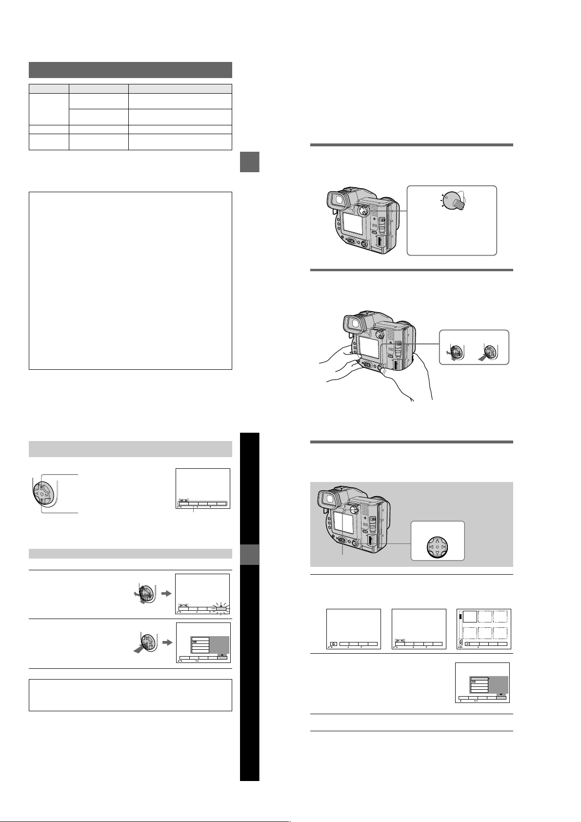
Setting the date and time
When you first use your camera, set the date and time. If these are not set, the
CLOCK SET screen appears whenever you tu rn on your camera.
Control button
POWER ON/OFF (CHG) lamp
Slide the POWER switch to the right to turn on the power.
1
The POWER ON/OFF (CHG) (green) lamp lights up.
Pressvon the control button.
2
The menu bar appears on t he LCD screen or on the
finder.
EFFECT F ILE SETUP
SELECT OK
Select [SETUP] withBon the control button,
3
then press the center
Select [CLOCK SET] withv/Von the control button, then press the
4
center
.
z
.
z
VIDEO OUT
/LANGUAGE
CLOCK SET
BEEP
LCD BRIGHT
EFFECT F ILE SETUP
SELECT CLOSE
CAMERA
MENU BAR OFF
CAMERA
13
1-3
14
VIDEO OUT
/LANGUAGE
CLOCK SET
BEEP
LCD BRIGHT
EFFECT F ILE SETUP
SELECT OK
200111
12:00:00A
CAMERA
CLOCK SET
M
2001 :/ / 1 1 12 00 AM
SELECT
Y/M/D
M/D/Y
D/M/Y
ENTER
CANCEL
OK
Page 11
Select the desired date display format with
5
on the control button, then press the
v/V
.
center
z
Select from [Y/M/D] (year/month/day), [M/D/Y]
(month/day/year), or [D/M/Y] (day/month/year).
Select the year, month, day, hour or minute
6
itemyouwanttosetwithb/Bon the control
button.
The item to be set is indicated with
Set the numeric value withv/Von the
7
control button, then press the center
enter it.
After entering the number,
item. If you se lected [D/M/Y ] in step
time on a 24-hour cycle.
Select [ENTER] withBon the controlbutton,
8
then press the center
moment to begin clock movement.
The date and time are entered.
v/V
moves to the next
v/V
at the desired
z
5
.
,setthe
CLOCK SET
2001 : 1 1 12 00 AM//
OK
SELECT/ADJUST
CLOCK SET
2001 :/ / 1 1 12 00 AM
OK
SELECT/ADJUST
to
z
CLOCK SET
2001/ :/ 1 7 12 00 AM
OK
SELECT/ADJUST
CLOCK SET
2001/ :/ 4 7 10 30 PM
OK
SELECT
To cancel the date and time setting
Select [CANCEL] withv/V/b/Bon the control button, then press the centerz.
Y/M/D
M/D/Y
D/M/Y
ENTER
CANCEL
Y/M/D
M/D/Y
D/M/Y
ENTER
CANCEL
Y/M/D
M/D/Y
D/M/Y
ENTER
CANCEL
Y/M/D
M/D/Y
D/M/Y
ENTER
CANCEL
Getting started
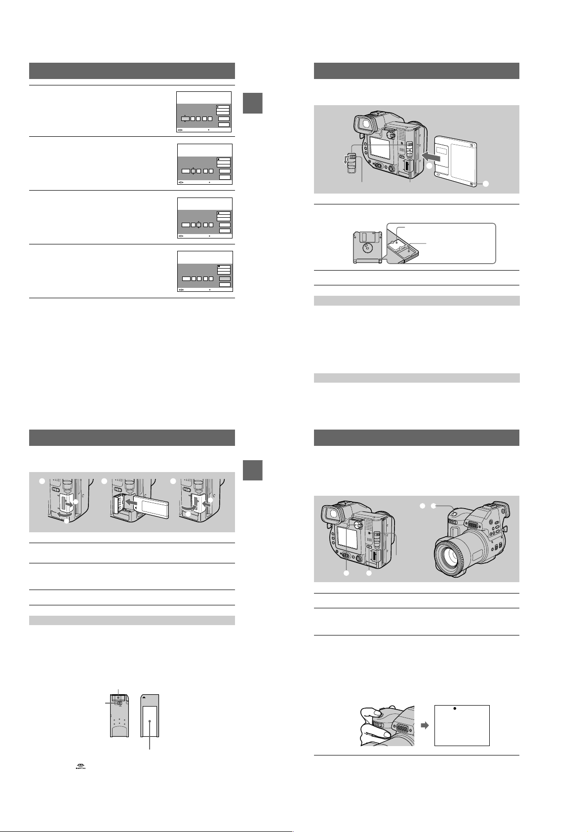
Inserting a floppy disk
2
EJECT lock
Check that the write protect tab is set to the recordable position for
1
recording.
DISK EJECT lever
Recordable/erasable
Unrecordable/unerasable
Insert the floppy disk until it clicks.
2
Usable floppy disks
• Size: 3.5 inch
• Ty pe : 2 HD ( 1. 4 4 M B)
• Format: MS-DOS format (512 bytes ×18 sectors)
Notes
• Do not insert the media other than the floppy disks desc ribe da bove.
• You cannot use th e optional MSAC-FD2M/FD2MA Floppy Disk Adaptor for Memory Stick.
• Never remove thefl oppyd isk, turn off the power, or change the position of the MS/FD selector
while the access lamp is lit up.
1
Inserting a “Memory Stick”
1 2 3
1
2
Open the “Memory Stick” cover.
1
Slide the cover in the direction of the arrow.
Insert the “Memory Stick.”
2
Insert the “Memory Stick” with the
slot as illustrated until it clicks.
Close the “Memory Stick” cover.
3
mark facing toward the “Memory Stick”
B
Removing the “Memory Stick”
Open the “Memory Stick” cover,thenpushthe“Memory Stick” once lightly.
Notes
• If you do not insert the “Memory Stick” firmly u ntil it clicks, a message such as “MEM ORY
STICK ERROR” will be di splayed.
• Never remove the “Memory Stick,” turn off the power, or change the position of the MS/FD
selector while the access lamp is lit up.
• You cannot record or edit images on a “Memory Stick” if the write-protect swit ch is set to the
LOCK position.
Ter mi na l
Write-protect
switch
LOCK
2
1
15
Getting started
Removing the floppy disk
While sliding the EJECT lock to the left, slide down the DISK EJECT lever.
16
Basic operations
B
Recording
Recording still images
Still images are recorded in JPEG format.
To record still images, slide the POWER switch to the right to turn on the power and
insert a floppy disk or a “Memory Stick.”
3, 4
Access lamp
1 2
Set the PLAY/STILL/MOVIE selector to STILL.
1
Select the recording media using the MS/FD selector.
2
MS: When recording on the “Memory Stick.”
FD: When recording on the floppy disk.
Press and hold the shutter button halfway down.
3
The beeps sound and the image is frozen. However, the image has not been
recorded yet. W hile the AE lock indica tor
automatically adjusts the exposure and focus of the captured image. When the
camera finishes the automatic adjustments, the AE lock indicator
flashing, then lights up, an d the camera is ready for recording.
If you release the shu tter button, the recording will be canceled.
is flashing, the camera
z
AE lock indicator (green)
flashes t lights up
zzzz stops
The position or shape of the write -protect switch depends on the type of the “Memory Stick.”
Label space
“Memory Stick” and are trademarks ofSony Corporation.
17
18
1-4
Page 12
Press the shutter button fully down.
4
The shutter clicks. “RECORDING” appears on the LCD screen or on the
finder, and the image will be recorded on the flop py disk or the “Memory
Stick.” When “RECORDING” disappears from the LCD screen or finder, you
can start the next recor ding.
Turning off the LCD screen
Press LCD ON/OFF switch to turn off the LCD screen. The battery life will be
longer.
RECORDING
For the number of images you can record on a floppy disk or a
“Memory Stick”
See page 48.
Notes
• When recor ding bright subjects, the color of the LCD screen may chan ge after the
AE is locked. However, this will not affect the r ecorded image.
• While the image is being recorded on a floppy disk or a “Memory Stick,” the access
lamp lights. When this lamp is lit, do not shake or strike the camera. Also, do not
turn the power off, not change the position of the MS/FD selector, or not remove the
battery pack/floppy dis k/“Memory Stick.” Otherwise, an image data breakdown
mayoccurandthefloppydiskorthe“Memory Stick” may become unusable.
• When you press the shutter button fully down at once, the camera starts recording
after the automatic adjustment is complete. However, the recording cannot be
carried out while the lamp (page 8) is flashing. (During this time, the camera is
charging the flash.)
Recording images with the finder
Turn the finder adjustment dial until the image appears clearly within the finder, then
record the image.
Finder adjustment dial
Note
The finder display is automatically tu rned off when your face is not near the finder.
19
BB
B Recording
B
LCD ON/OFF
switch
Notes
• You cannot turn off the LCD scree n when [DEMO] is set to [ON] in the menu settings .
• When both the LCD screen and the finder display are turne d off, yo u can only use followings:
—LCD ON/OFF switch
—POWER switch
—PLAY/STILL/MOVIE selector
—Shutter button
—MS/FD selec tor
—STEADY SHOT ON/OFF switch
—FOCUS AUTO/MANUAL switch
—Focus ring
Checking the last recorded image (
You can check the last recorded image by clearing the menu bar from the screen
(page 41) and pressing
To return to the normal recording mode: press the shutter button lightly, or select
[RETURN] with
To delete the image: first select [DELETE] on the Quick Review screen with
on the control button and press the centerz, and then select [OK] withv/Von the
control button and press the center
on the control button.
b
on the control button and then press the centerz.
b/B
.
z
Quick Review
)
b/B
Adjusting the brightness of the LCD screen
Adjust the brightness with the [LCD BRIGHT] item in the menu settings (page 47).
This adjustment does not affect the brightness of the images recorded on the floppy disk
or the “Memory Stick.”
20
Using the zoom feature
Zoom lever
T side: for
telephoto
(subject
appears closer)
W side: for wideangle (subject
appears farther
away)
If you cannot get a sharp focus on a close subject
Slide the zoom lever to the W side and move closer to the subject until the focus is
sharp (page 54).
Minimum focal distance to the subject
W side:About 25 cm (9 7/8 inches)
T side: About 80 cm (31 1/2 inches)
Torecord even closer subjects, see page 54.
Digital zoom function
This camera has a digital zoom function.
Digital zoom enlarges the image by digital processing, and it starts to function when
the zoom exceeds 10×.
T
W
The T-side of the ba r shows the
digital zooming zone
.
Using digital zoom
• The maximum zoom magnification is 20×.
• Digital zooming deteriorates the picture quality. When digital zoom is not
necessary,set [DIGITAL ZOOM] to [OFF] in the menu settings (page 45).
Note
Digital zoom does not work for moving images.
B Recording
Activating the SteadyShot function
When the SteadyShot function is workin g, the camera compe nsates for camerashake.
STEADY SHOT
ON/OFF switch
Set the STEADY SHOT ON/OFF switch to ON. The (SteadyShot) indicator
appears on the LCD screen or on the finder.
Notes
• The SteadyShot function will not correct excessive camera-shake.
• If you use a wide conversion lens (not supplied), this lens may infl uence the SteadyShot
function.
The indicators on the LCD screen or on the finder during
recording
Press DISPLAY to turn on/off the indicators o n the LCD screen or on the finder. See
page 89 for a detailed description of the indicators.
DISPLAY
Notes
• You cannot turn o ff the (self-timer) indicator and some o f the indicators used in advanced
operations.
• The indicators on the LCD screen or on the finder are not r ecorded.
21
22
1-5
Page 13
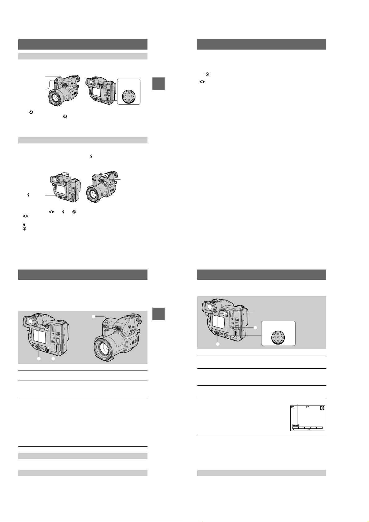
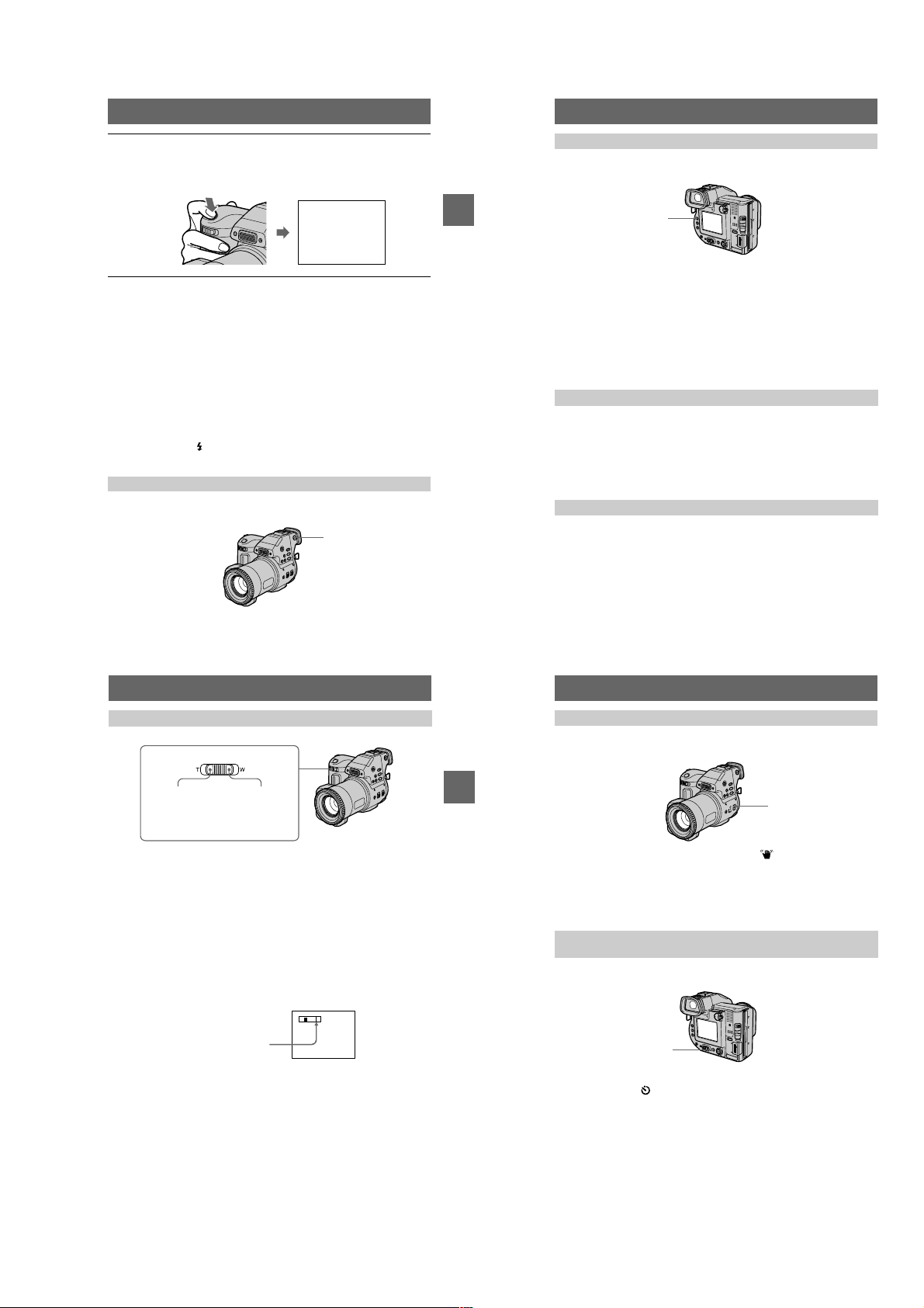
Using the self-timer
"b/B"
When you use the self-timer function, the subject is recorded 10 seconds after you
press the shutter button.
Self-timer lamp
Shutter button
Select on the LCD screen or on the finder with
then press the center
on the finder, and the subject is recorded 10 seconds after you press the shutter
button. The self-timer lamp flashes after you press the shutter button until the image
is recorded.
. The (self-timer) indicator appears on the LCD screen or
z
b/B/v/V
Control button
on the control button,
Recording images with the flash
Press OPEN (FLASH) to pop up the flash. The initial setting is AUTO (no
indication). In this mode, the flash automatically strobes when the surroundings
become dark. To change the flash mo de, press (Fl ash) repeatedly so th at the flash
mode indicator appears on the LCD screen or o n the finder. This setting can be set
only when the flash is popped up.
OPEN
(FLASH)
(Flash)
BB
B Recording
B
Notes
• The recommended shooting distance is 0.6 to 2. 5 m (23 5/8 inches to 8 1/3 feet).
• Attaching a conversion lens (not supplied) may block the light from the flash and the recorded
image may be eclipsed.
• You cannot use th e built-in flash and an external strobe at the same time.
• The indicator appears when the flash is not popped up under situations that you should use
the flash.
• Auto red-eye reduction may not produce the desired red-eye reducti on effects depending
on individual differences, the distance to the s ubject, if the subject does not see the pre-strobe,
or other conditions. In addition, re d-eye reduction effects are also difficult to obtain if you
select a slow shutter speed in shut ter priority mode of the PROGRAM AE function.
• The flash effect is not obtained easily wh en you use forced flash in a bright location.
Each time you pre ss the button, the indicator changes as follows.
(No indication)
eye phenomenon.
You can change the amount of the flash light w ith [FLASH LEVEL] in th e menu
settings (page 46).
tttt
Auto red-eye reduction : The flash strobes before recording to reduce the red-
Forced flash : The flash strobes regardless of the surrounding brightness.
No flash : The flash does not strobe .
(No indication)
Recording moving images
Moving images with audio are recorded in MPEG f ormat.
To record moving images, slide the POWER switch to the right to turn on the power
and insert a floppy disk or a “Memory Stick.”
3
1 2
Set the PLAY/STILL/MOVIE selector to MOVIE.
1
Select the recording media using the MS/FD selector.
2
MS: When recording on the “Memory Stick.”
FD: When recording on the floppy disk.
Press the shutter button fully down.
3
“REC” appears on the LCD screen or finder, and the image and sound are
recorded on the flo ppy disk or “Memory Stick.”
If you press the shutter button momentarily
The image and sound are recorded for 5 seconds. The recording time can be set
to 10 or 15 seconds with [REC TIME SET] in the menu settings (pa ge 45).
If you hold the shutter butt on down
The image and sound are rec orded while the shutter button is held down for up
to 60 seconds. However, when [IMAGE SIZE] in the menu settings is set to
[320×240], the maximum recording time is 15 seconds (page 48).
Adjusting the brightness of the LCD screen, zooming or using the self-timer
See pages 20 to 23.
LCD screen or finder indicators during recording
Press DISPLAY to turn on/off the indicators on the LCD screen or on the finder.
These indicators are not recorded. See page 89 for a detailed description of the indicators.
23
25
BB
B Recording
B
24
B
Playback
Playing back still images
Access lamp
3, 4
2
Control button
1
Set the PLAY/STILL/MOVIE selector to PLAY.
1
The last recorded image (still or moving) appears on the LCD screen or on the finder.
Select the playback media using the MS/FD selector.
2
MS: When playing back images in the “Memory Stick.”
FD: When playing back images in the floppy disk.
Pressvon the control button to display the menu bar on the LCD
3
screen or on the finder.
Select the desired still image with the
4
control button.
Press
on the LCD screen or on the finder,then press b/B.
: Todisplay the preceding image.
"b
B":Todisplaythenextimage.
on the control button to select"b/
v/V/b/B
When the menu bar is not displayed
Youcan directly select and play back the image with b/B onthe control button.
Notes
•
Youmight not be able to correctly play back images recorded with this camera on other equipment.
• You may not be able to play back images whose image sizes are larger than the maximum
image size that can be used with this camera for recording.
LCD screen or finder indicators during still image playback
Press DISPLAY to turn on/off the indicators on the LCD screen or on the finder.
See page 90 for a detailed descriptionof the indicators.
26
B"
120min
640
DELETE
INDEX FILE SETUPTOOL
SELECT FILE BACK/NEXT
6/8
1-6
Page 14
Playing back moving images
(playback)/
Access lamp
3–5
2
Control button
1
Set the PLAY/STILL/MOVIE selector to PLAY.
1
The last recorded imag e (still or moving) appears on the LCD screen or on the
finder.
Select the playback media using the MS/FD selector.
2
MS: When playing back images in the “Memory Stick.”
FD: When playing back images in the floppy disk.
Pressvon the control button to dis play the menu bar on the LCD
3
screen or on the finder.
Select the desired moving image with the
4
control button.
Moving images are displayed one size smaller than
still images.
Press
on the LCD screen or on the finder, then press
B"
b/B
: To display the preceding image.
"b
: To display the next image.
B"
on the control button to sel ect"b/
v/V/b/B
.
"b/B"
120min
DELETE
INDEX FILE SETUPTOOL
SELECT
160
FILE BACK/NEXT
Select theB(playback) button on the LCD
5
screen or on the finder with
the control button, then press the center
.
z
The moving image and so und are played back.
During playback,
(pause).
BB
B Playback
B
To pause playback
SelectX(pause) on the LCD screen or on the find er withv/V/b/Bon the control
button, then press the center
(playback) changes to
B
v/V/b/B
.
z
on
X
B
X (pause) button
120min
160
DELETE
INDEX FILE SETUPTOOL
SELECT OK
Playback bar
6/8
0:05
When the menu bar is not displayed
You can directly select the image withb/Bon the control button, and p lay back the
image and sound by pr essing the center
playback, playback is paused.
. When you press the centerzduring
z
Adjusting the volume
Press VOL +/– to adjust th e volume.
LCD screen or finder indicators during moving image playback
Press DISPLAY to turn on/off the indicators on the LCD screen or on the finder.
6/8
See page 90 for a detailed description of the indicators.
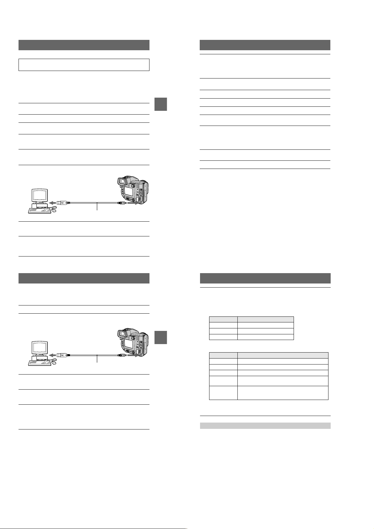
Viewing images using a
computer
You can view or modify data recorded with your camera using application software
on a computer, or attach it to an E-mail.
Viewingimagesusingafloppydiskdrive
For Windows 98 users
Start up your computer and insert the floppy disk into the disk
1
drive of your computer.
Open [ My Computer] and double-click [ 3 1/2 Floppy (A:)].
2
Double-click the desired data file.
3
Copying a file to the hard disk of your computer bef ore viewing it is
recommended when playing back an au dio file or a moving image. If you play
back the file directly from the floppy disk, the image and sound may break off.
Viewing images on a computer connected using the USB cable
This section describes the method for viewing images on a computer using the
supplied USB cable.
What is the USB connection? : You can connect the camera to your computer
using the USB cable, to view or modify the images stored in a floppy disk or
“Memory Stick.”
To make the USB connection: You have to install the USB driver in your
computer beforehand.
Be sure to also see the operation manuals for your computer and application
software.
Notes
• Data recorded with your camera is stored in the following formats. Make sure that applications
that support these file formats are installed on your computer.
—Still images (other than TEXT mode, un co mpre ss ed m ode and Clip Motion): JPEG format
—Moving images/audio: MPEG format
—Uncompressed modestill images: TIFF format
—TEXT mode/Clip Motion: GIF form at
• ActiveMovie Player (DirectShow) must be installed (to play back moving pictures).
• QuickTime 3.2 or newer must be installed (to play back moving pi ctures).
27
28
xRecommended computer environment
Recommended Windows environment
OS:Microsoft Windows 98, Windows 98SE, Windows Me, Windows 2000 Professional
The above OS is required to be installed at the factory.
Operation is not assured in an environment up graded to the operating systems described
above.
CPU:MMX Pentium 200 MHz or faster
The USB connector must be pr ovided a s standard.
Recommended Macintosh environment
Macintosh computer with the Ma c OS 8.5.1/8.6/9.0
The above OS is required to be insta lled at the factory.
BB
B Playback
B
However, note that the update to Mac OS 9.0 should be used for the fol lowing m odels with the
Mac OS 8.6 standard insta llation at the factory:
iMac with a slot loading type CD-ROM drive, iBook, Power Mac G4
The USB connector must be pr ovided a s standard.
Notes
• Operations are not guaranteed for either theWindows or Macintosh environment if you connect
two or more USB equipment to a si ngle computer at the same time (except for the USB
keyboard and mouse which are provided as standard), or whe n using a hub.
• Depending on the type of USB equipment that is used simul taneously, some eq uipment may
not operate.
• Operations are not guaranteed for all the recommende d computer environments mentioned
above.
• Windows and ActiveMovie, DirectS how a re either registered tradema rks or trademarks of
Microsoft Corporation in the United States and /or other countries.
• Macintosh and Mac OS, QuickTime are either registered trademarks or trademarks ofApple
Computer, Inc.
• All other product names mentioned herein may be t he trademarks or registered trademarks of
their respective companies. Furthermore, “™” and “®” arenotmentionedineachcaseinthis
manual.
29
30
1-7
Page 15
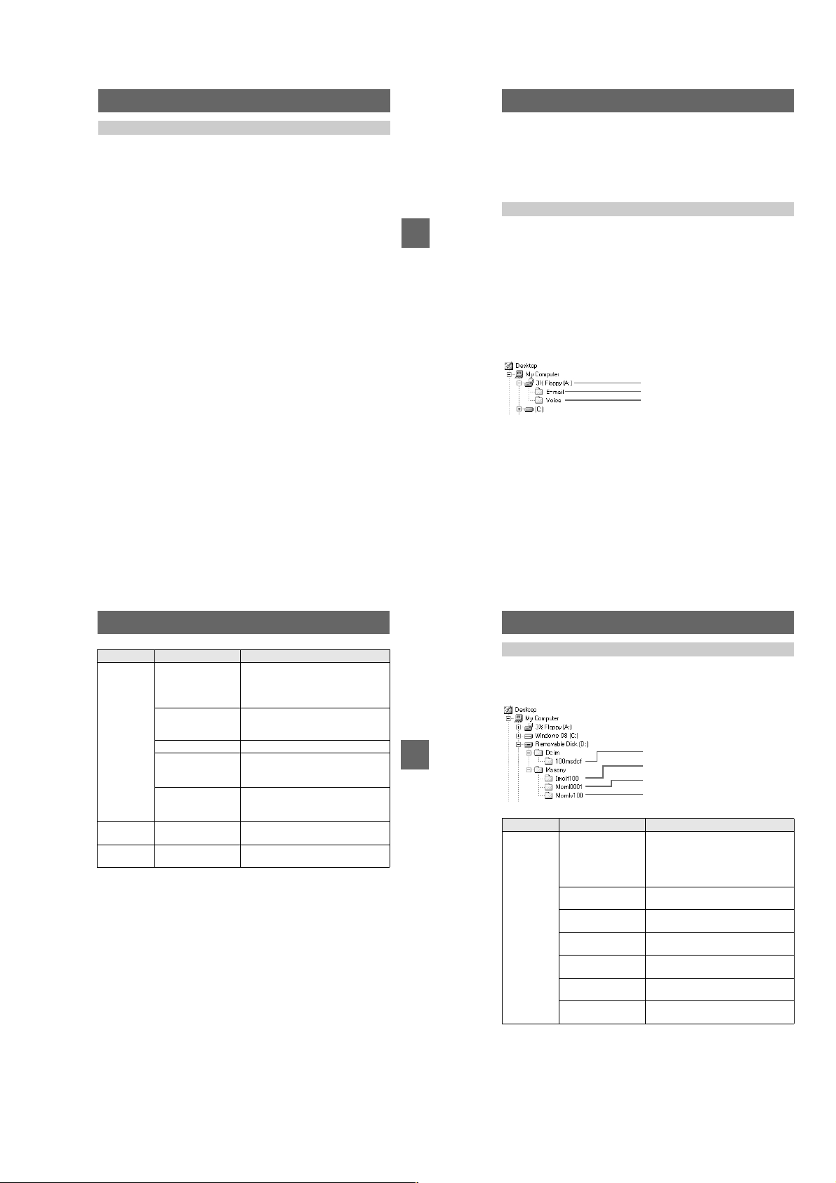
xInstalling the USB driver
Do not connect your camera to your computer before installing the
USB driver.
First, install the U SB driver to the computer. The USB driver is contained toge ther
with application software for viewing images on a CD-ROM which is supplied with
your camera.
If the drive is not recognized properly, see “Troubleshooting” on pag e 79.
For Windows 98, Windows 98SE, Windows Me and Windows
2000 Professional users
Make sure that the camera is not connected to your computer.
1
Do not connect the US B cable in this step.
Turn on your computer and allow Windows to load.
2
Insert the supplied CD-ROM in the CD-ROM drive of your computer.
3
The application software screen appears.
Click “USB Driver Installation for Windows 98/98SE, Windows Me,
4
Windows 2000”.
USB driver installation starts.
Follow the on-screen messages to install the USB driver.
5
If the message appears after the installation to verify that you restart the
computer, restart the computer.
Connect the USB jack (mini-B) on your camera with the USB
6
connector on your computer using the supplied USB cable.
Follow the on-screen messages to recognize the hardware.
9
The Add Hardware Wizard starts twice because two different USB drivers are
installed. Be sure to allow the installation to complete without interrupting it.
If the message appears after the installation to verify that you restart the
computer, restart the computer.
For Macintosh users
Turn on your computer and allow the Mac OS to load.
1
Insert the supplied CD-ROM in the CD-ROM drive of your computer.
2
Double-click the CD-ROM drive icon to open the window.
BB
B Playback
B
3
Double-click the icon of the hard disk containing the “System
4
Folder” to open the window.
Move the following two files from the window opened in step 3 to
5
the “System Folder” icon in the window opened in step
and drop).
• Sony USB Driver
• Sony USB Shim
When “PuttheseitemsintotheExtensionsfolder?” appears, click
6
“OK.”
Restart your computer and connect the USB cable.
7
(drag
4
To t he U SB
connector
Computer
Insert a floppy disk or a “Memory Stick” into your camera, and set
7
the MS/FD selector to the appropriate position according to the
media inserted.
Connect the AC power adaptor and turn on your camera.
8
“USB MODE” appears on the LCD screen or on the finder of your camera and
the camera is set to c ommunication standby mode. Your computer recognizes
the camera, and the Windows Add Hardwa re Wizard starts.
To the USB
jack
USB cable
Push the connector as far
as it will go
xViewing images
For Windows 98, Windows 98SE, Windows Me and Windows
2000 Professional users
Turn on the power of your computer and allow Windows to load.
1
Connect one end of the supplied USB cable to the USB jack (mini-
2
B) on the camera and the other end to the USB connector on your
computer.
To t he U SB
connector
Computer
Insert a floppy disk or “Memory Stick” into your camera, and set
3
the MS/FD selector to the appropriate position according to the
media inserted.
Connect the AC power adaptor to your camera and then to a w all
4
outlet (mains) and turn on the power of your camera.
“USB MODE” appears on the LC D screen or on the finder of the camera.
Open “My Computer” on Windows and double-click the newly
5
recognized drive, “Removable Disk”(Example (D:)
The folders inside the f loppy disk or “Memory Stick” are displayed.
If the drive is not recognize d properly, see “Troubleshooting” on pag e 79.
∗ Drive identifier depends on your computer.
To the USB
jack
USB cable
Push the connector
as far as it will go
∗
).
31
32
Select and double-click the desired image/audio file from the
6
folder.
For the detailed folder and file name, see “Image file storage destinations and
image file names” (page 36).
When viewing an image in a floppy disk
Desired file type
Audio* “Vo i c e ” foldertAudio file*
E-mail image “E-mail” folder
Other files Image file
BB
B Playback
B
When viewing an image in a “Memory St ick ”
Desired file type
Still image “Dcim” folder t
Moving image* “Mssony” folder
Audio* “Mssony” folder
Clip Motion
image
E-mail image
TIFF image
(uncompressed)
∗ Copying a file to the hard disk of your computer before viewing it is recommended. If
you play back the file directly from the floppy disk or “Memory Stick,” the image and
sound may break off.
For Windows Me or Windows 2000 Professional users
When using Windows Me or Windows 2000 Professional, the following procedures
are recommended when disconnecting the USB cable from your computer, ejecting
the floppy disk or “Memory Stick” from the camera, or changing the position of the
MS/FD selector, while it is connected to your computer.
1 Stop the drive by clicking on the “Unplug/Eject” icon in the task tray.
2 Carry out the operation after the message, confirming the safe removal of the
hardware, appears.
Double-click in this order
Double-click in this orde
“Dcim” folder
“Mssony” folder
t
Image file
r
“100msdcf” folder
t
“Moml0001” foldertImage file*
t
“Momlv100” folder
t
“100msdcf” folder
t
“Imcif100” folder
t Image file
t Audio file*
t Image file
t
Image file
33
34
1-8
Page 16
Notes on using your computer
Flop py di s k/“Memory Stick”
• Format the floppy disk or “Memory Stick” only using this camera
(page 72). You cannot format the floppy disk or “Memory Stick” using
a computer via the USB cable .
• Use only a DOS/V 2HD format floppy disk. Other disks will not be recognized by a
computer.
• Do not optimize the “Memory Stick” on a Windows machine. This will shorten the
“Memory Stick” life.
• Do not compress the data on the floppy disk or “Memory Stick.” Compressed files
cannot be played back on your camera.
Software
• Depending on your application software, the file size may increase when you open
a still image file.
• When you load an image modified using the supplied retouching software from
your computer to the camera or when you directly modify the image on the camera,
the image format will differ so the “FILE ERROR” message may appear and you
maybeunabletoopenthefile.
• Depending on your application software, only the first frame of a Clip Motion
image may be displayed.
Communications with your computer
Communications between your camera and your computer may not recover after
recovering from Standby or Sleep.
Other
When connecting the camera to a computer or when using an external power source,
remove the battery pack from inside the camera.
Image file storage destinations
and image file names
Image files recorded with your camera are grouped in folders by recording mo de.
Images in a floppy disk and ones in a “Memory Stick” have different file names. The
meanings of the file nam es are as follows.
When using floppy disks
stands for any number within the range from 001 to 999.
sss
stands for one of the following characters below.
B
Playback
f
S: Still image file recorded at 640×480 size
F: Still image file of more than 640×480 size
V: Moving image file recorded at 160×112 size
W: Moving image file recorded at 320×240 size
T: Still image file recorded in TEXT mode
C: Clip Motion file recorded in NORMAL mode
M: Clip Motion file recorded in MOBILE mode
For Windows 98 users (The drive recognizing the floppy disk is
[A].)
Storage destination containing still image,
moving image, TEXT mode image and Clip
Motion image data
Folder containing E-mail mode image data
Folder containing VOICE mode audio data
Location File Meaning
3 1/2 Floppy
[A:]
E-mail fold er MVC-
Voice f older MVC-
• The numerical portions of the following files are the same.
—An image file recorded in E-MA IL m ode and its corresponding small-size image file
—An audio file recorded in VOICE mode and its correspondin g image file
—An image file recorded in TEXT mode and i ts corresponding index image file
—An image file recorded with Clip Mot ion and its corresponding index image file
INDEXdisplay files other than the TEXT mode and Clip Motion files are played back only onthis
•
camera.
MVC-
MVC-
MVC-
MVC-
MVC-
.JPG • Still image file recorded normally
sssf
sssf
sssf
sssf
sssf
sss
sss
• Still image file recorded in
— E-MAIL mode (page 51)
— VOICE mode (page 51)
.411 • INDEX display file
Thisfilecanonlybeplayedbackon
your camera.
.MPG • Moving image file
.GIF • Still image file recorded in
— TEXT mode (page 52)
— Clip Motion (page 49)
.THM • Index image file recorded in
— TEXT mode (page 52)
E.JPG • Small-size image file recorded in E-
A.MPG • Audio file r ecorded in VOICE mode
— Clip Motion (page 49)
MAIL mode (page 5 1)
(page 51)
35
36
When using “Memory Stick”s
stands for any number within the range from 0001 to 9999 .
ssss
For Windows 98 users (The drive recognizing the camera is
“D.”)
Folder containing still image recorded in
normal mode, TEXT mode image and Clip
Motion image data
Folder containing E-MAIL mode and TI FF
BB
B Playback
B
Folder File Meani ng
100msdcf DSC0
CLP0
CLP0
MBL0
MBL0
TXT0
TXT0
ssss
ssss
ssss
ssss
ssss
ssss
ssss
mode image data
Folder containing movi ng image data
Folder containing VOICE mode audio data
.JPG • Still image file recorded normally
• Still image file recorded in
— E -MAIL mode (page 51)
— TIFF mode (page 53)
— VOIC E mode (page 51)
.GIF • Clip Motion file recorded in NORMAL
mode (page 49)
.THM • Index image file of Clip Motion file
recorded in NORMAL mode
.GIF • Clip Motion file recorded in MOBILE
mode (page 49)
.THM • Index image file of Clip Motion file
recorded in MO BILE mode
.GIF • Still image file recorded in TEXT mode
(page 52)
.THM • Index image file of still image file
recorded in TE XT mode
37
38
1-9
Page 17
Folder File Mea ning
Imcif100 DSC0
DSC0
Moml0001 MOV0
Momlv100 DSC0
The numerical portions of the foll owing files are the same.
—A small-size image file recorded in E-MAIL mode and its corresponding image file
—An uncompressed image file recorded in TIFF mode and its corresponding i mage file
—An audio file recorded in VOICE mode and its correspondin g image file
—An image file recorded in TEXT mode and i ts corresponding index image file
—An image file recorded with Clip Mot ion and its corresponding index image file
Tips
The digital still camera saves recorded images as digital data. The format of the
saved data is called as the file format. The formats that can be used with this
camera are as follows:
JPEG format
Most digital still cameras, operating systems of computers, and browser software
adopt this format. This format is able to compress files without appreciable
deterioration. However, if the image is compressed and saved on repeated
occasions, the image will deteriorate. This camera re cords still images u sing the
JPEG format for nor mal recording.
GIF format
Using this format, the image will not deteriorate even if the image is compressed
and saved on repeated occasions. This format limits the number of colors to 256
colors. This camera records still images using the GIF format in Clip Motion
(page 49) or TEXT mode (page 52).
TIFF format
Stores shooting images without compression, so the image does not deteriorate.
Most of operating systems and applications correspond to this format. This camera
records still image s using the TIFF f ormat for the TIFF mode (page 53) .
MPEG format
This format is very typical for moving images. This camera records audio using
the MPEG format for the moving images recording and the VOICE mode
(page 51).
.JPG • Small-size image file recorded in E-
ssss
ssss
ssss
ssss
MAIL mode (page 5 1)
.TIF • Uncompressed image file recorded in
TIFF mode (page 53)
.MPG • Moving image file recorded normally
.MPG • Audio file rec orded in VOICE mode
(page 51)
Advanced operations
Before performing advanced
operations
This section describes the basic control methods that are frequently used for
“Advanced operations.”
How to use the PLAY/STILL/MOVIE selector
The PLAY/STILL/MOVIE selector selects whether you can use your camera to
BB
B Playback
B
record or play back and edit images. Set the selector a s follows before starting to
operate your camera.
PLAY
STILL
MOVIE
PLAY: To play back or edit
images
STILL: To record still images,
VOICE images and Clip
Motion images
MOVIE: To record moving
images
How to use the control button
The control button is used to select the buttons, i mages and menus displayed on the
LCD screen or on th e finder of your camera an d modify the settings. T he operation
methods that a re frequently used for “Advanced operations” are described below.
Select
Set (enter)
Turning on/off the operation buttons (menu bar) on the LCD screen or
on the finder
Press v to display the menu bar
on the LCD screen or on the finder.
DELETE
Press V to clear the menu bar
from the LCD screen or on the
finder.
Note
You cannot clear the menu bar on the IN DEX screen (page 61 ).
INDEX FILE SETUPTOOL
SELECT OK
Menu bar
MENU BAR OFF
Selecting items or images on the L CD screen or on the finder
Pressv/V/b/Bon the control
1
button to select the item you
want to set or the image you
want to display.
The color of theselected item or the
frame of the selected image
changes from blue to yellow.
Press the centerzto enter
2
the item.
Repeat steps
each function.
1
and2to execute
DELETE
INDEX FILE SETUPTOOL
SELECT OK
VIDEO OUT
/LANGUAGE
CLOCK SET
BEEP
LCD BRIGHT
DELETE
INDEX FILE SETUPTOOL
SELECT CLOSE
MENU BAR OFF
The “Advanced operations” section of this manual refers to
selecting and entering items by the above procedure as
“Select [item name].”
39
40
How to change the menu settings
Some of the advanced operations for yo ur camera are executed by selecting menu
items displayed on th e LCD screen or on the finder with the control button.
1–3
Control button
Before performing advanced operations
PLAY/STILL/MOVIE selector
Pressvon the control button to display the menu bar.
1
The menu bar appears as follows according to the position of the PLAY/STILL/
MOVIE selector.
STILL/MOVIE
EFFECT F ILE SETUP
CAMERA
SELECT OK
Select the desired item withv/V/b/Bon the
2
control button, then press the center
The color of the selected item changes from blue to
yellow, and whenyou press the center
that can be set for its item are displayed.
Note
The displayed items are change d according to the position
of the MS/FD selector.
Select the desired setting withv/V/b/Bon the control button, then
3
press the center
MENU BAR OFF
z
PLAY (single mode)
INDEX FILE SETUPTOOL
SELECT OK
.
DELETE
, the settings
z
MENU BAR OFF
.
z
PLAY (INDEX mode)
DELETE
SELECT SINGLE DISPLAY
VIDEO OUT
/LANGUAGE
CLOCK SET
BEEP
LCD BRIGHT
DELETE
INDEX FILE SETUPTOOL
SELECT OK
2001 7 4 10:30PMMVC–001F
FILE SETUPTOOL
NTSC
41
1-10
To cancel the setup
PressVon the control button repeatedly until the LCD screen or finder returns to the
menu bar display in step
1
. To clear the menu bar, pressVagain.
42
Page 18
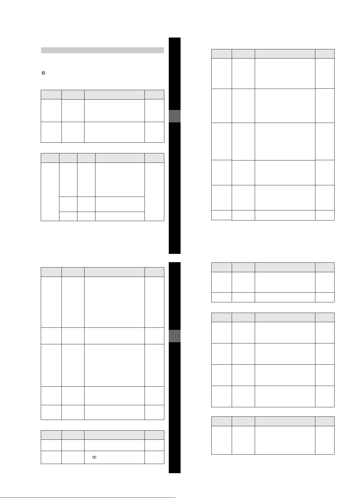
Menu settings
Menu items that can be modified differ depending on the positions of the PLAY/
STILL/MOVIE selector or the MS/FD selector. The LCD screen or the finder shows
only the items you can operate at the moment. Initial settings are indicated with
(self-timer)
Records with the self-timer (page 23).
x
EFFECT
Item Setting Description
P. EFFECT SOLARIZE
DATE/
TIME
B&W
SEPIA
NEG.ART
OFF
x
DAY &
TIME
DATE
OFF
x
Sets the image special effects (page 60). STILL
Sets whether to insert the date and time
into the image (page 60).
PLAY/STILL/
MOVIE selector
MOVIE
STILL
FILE
Item-1 Item-2 Setting Description
DISK
TOOL
(When the
MS/FD
selector is
set to FD.)
FORMAT OK Formats a floppy disk (page 72).
CANCEL Cancels formatting of a floppy
DISK
OK Copies all data stored in a floppy
COPY
CANCEL Cancels the disk copy.
CANCEL Goes back to the [DISK TOOL]
Once you format a floppy disk,
all of the data, includi ng
protected images are deleted. Be
sure to check for images before
you format a floppy disk.
disk.
disk to another disk ( page 70).
item.
PLAY/STILL/
MOVIE
selector
PLAY
STILL
MOVIE
Item Setting Description
.
Before performing advanced operations
FORMAT
(When the
MS/FD
selector is
set to MS.)
FILE
NUMBER
CLIP
MOTION
IMAGE
SIZE
(When the
MS/FD
selector is
set to FD.)
IMAGE
SIZE
(When the
MS/FD
selector is
set to MS.)
IMAGE
SIZE
OK Formats a “Memory Stick.” Once you
CANCEL Cancels formatting of a “Memory
SERIES Assigns numbers to files in sequence
NORMAL Resets the file number that starts from
x
160×120
(NORMAL)
80×72
(MOBILE)
CANCEL Cancels Clip Motion.
1600× 1200
x
1600 (3:2)
1600 (ECM)
1024×768
640×480
1600 (FINE)
x
1600 (3:2) F
1024 (FINE)
640 (FINE)
320×240
160×112
x
format the “Memory Stick,” all of the
data, including protected images are
deleted. Be sure to check for images
before you format a “Memory Stick.”
Stick.”
even if the floppy disk or “Memory
Stick” is changed. Note that file
numbers are not in sequence between a
floppy disk and “Memory Stick.”
001 or 0001 each time the floppy disk or
“Memory Stick” is changed.
Sets the image size and number of
frames for creating GIF format
animation (page 49).
Up to 10 frames can be recorded.
Up to 2 frames c an be recorded.
Selects the image size when recording
still images.
Selects the image size when recording
still images.
Selects the MPEG image size when
recordingmovingimages.
PLAY/STILL/
MOVIE
PLAY
STILL
MOVIE
STILL
MOVIE
STILL
STILL
STILL
MOVIE
selector
Item Setting Description
REC MODE TIFF Records a TIFF (uncompressed) file in
TEXT Reco rds a GIF file in blac k-and-white.
VOICE Records an audio file (with a still image)
E-MAIL Records a small-size (320×240) JPEG
NORMAL Records an image using the no rmal
x
REC TIME
SET
SLIDE
SHOW
(Only in
PLAY
(single)
mode)
PRINT
MARK
PROTECT ON Protects images against accidental
15 sec Selects the r ecording time for moving
10 sec
5sec
x
INTERVAL
REPEAT A slide show can be repeated. (When
START Starts the slide show.
CANCEL Cancels t he slide show settings or
ON Marks the still images to be printed
OFF Unmarks the print m ark of the still
x
OFF Releases protection of images.
x
addition to the JPEG file when the MS/
FD selector is set to M S.
in addition to the JPEG file.
file in addition to the selected image
size.
recording mode.
images.
Sets the slide show interval.
3 sec/5 sec/10 s ec/30 sec/1 min
x
using the floppy disk, a sl ide show is up
to approx. 20 minutes)
ON/OFF
x
execution.
(page 71).
images.
erasure (page 65).
CAMERA
Item Setting Description
DIGITAL
ZOOM
SHARPNESS
ON Uses digital zoom. STILL
x
OFF Does not use digital zoom.
+2 to –2 Adjusts the sharpness of the image.
The indicator appears (except when
the setting is 0).
PLAY/STILL/
MOVIE
selector
STILL
MOVIE
PLAY
PLAY
PLAY
PLAY/STILL/
MOVIE
selector
STILL
43
45
44
Item Setting Description
FLASH
LEVEL
EXPOSURE +2.0EV to
HIGH Makes the flash level higher than
NORMAL Normal setting.
x
LOW Makes the flash level lower than normal.
–2.0EV
normal.
Adjusts the exposure before recording. STILL
TOOL
Item Setting Description
FD
COPY
(When the
MS/FD
selector is
Before performing advanced operations
set to FD.)
COPY
(When the
MS/FD
selector is
set to MS.)
RESIZE
(When the
MS/FD
selector is
set to FD.)
RESIZE
(When the
MS/FD
selector is
set to MS.)
t
FD Copies the image to a f loppy disk. PLAY
t
MS Copies the image to a “Memory Stick.”
FD
CANCEL Cancels copying of the image (page 68).
MS
t
MS Copies the image to a “Memory Stick.” PLAY
t
FD Copies the image to a floppy di sk.
MS
CANCEL Cancels copy ing of the image (page 68).
1600× 1200
1024×768
640×480
CANCEL
1600 (FINE)
1024 (FINE)
640 (FINE)
CANCEL
Changes the recorded image size in
PLAY (single) mode (page 67).
Changes the recorded image size in
PLAY (single) mode (page 67).
SETUP
Item Setting Description
DEMO
STBY/ON
x
OFF
Displayed only when you use the AC
power adaptor in STILL or M OVIE
mode. When [ON] is selected, a
demonstration will start if you do not
operate your camera for about 10
minutes. To stop the demonstration, turn
off your camera.
PLAY/STILL/
MOVIE
STILL
MOVIE
PLAY/STILL/
MOVIE
PLAY
PLAY
PLAY/STILL/
MOVIE
STILL
MOVIE
selector
selector
selector
46
1-11
Page 19
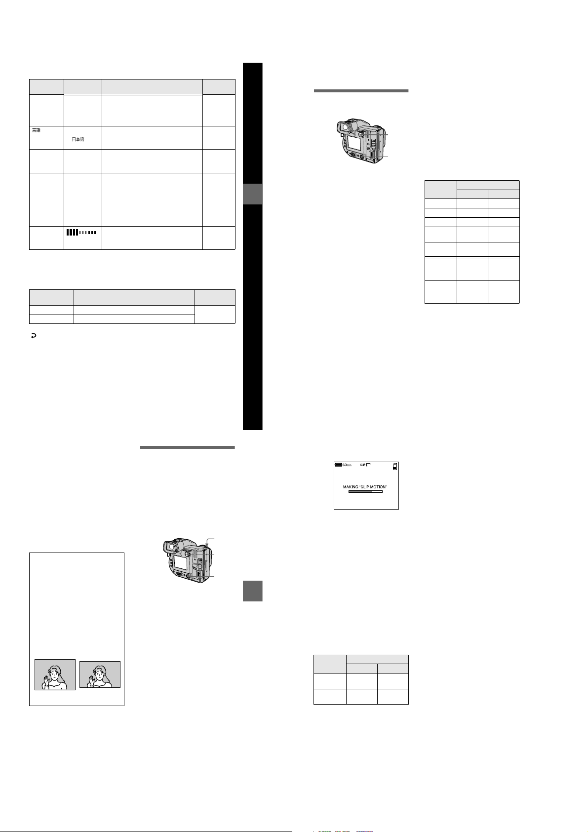
Item Setting Description
VIDEO
OUT
LAN GUAGE
CLOCK
SET
BEEP SHUTTER Turns on the shutter sound only. (The
NTSC Sets the video output signal to NTSC
PAL Sets the video output signal to PAL
/
ENGLISH Displays the menu items in English. PLAY
x
mode (e.g., Japan, the USA).
mode (e.g., Europe).
/JPN Displays the menu items in Japanese.
— Sets the date and time (page 14). PLAY
shutter sound is heard when you press
ON Turns on the beep/shu tter sound (when
x
the shutter button.)
you press the control button/shutter
button) .
OFF Turns off the beep/shutter so und.
LCD
BRIGHT
Adjusts the LCD screen brightness
using +/- on the LCD screen or on the
finder.
INDEX (Only in PLAY (single) mode)
Displays six images at a time (PLAY (INDEX) mode).
DELETE (Only in PLAY (single) mode)
Setting Description
PLAY/STILL/MOVIE
OK Deletes the displayed image. PLAY
CANCEL Cancels deleting of the image.
(Return) (Only in PLAY (INDEX) mode)
Returns to PLAY (single) mode.
PLAY/STILL/
MOVIE
selector
PLAY
STILL
MOVIE
STILL
MOVIE
STILL
MOVIE
PLAY
STILL
MOVIE
PLAY
STILL
MOVIE
selector
Various recording
B
Setting the image size
(IMAGE SIZE)
1
2, 3
Set the PLAY/STILL/MOVIE
1
selector to STILL or MOVIE.
Select [FILE] and then
2
Before performing advanced operations
[IMAGE SIZE] from the menu.
Select the desired image
3
size.
Still image size:
• When the MS/FD selector is set
to FD
1600×1200, 1600 (3:2) *,
1600 (ECM), 1024×768,
640×480
(ECM): The image quality
deteriorates, however, the number of
images you can record increas es. If
you give priority to the image quality,
select [1600×1200].
• When the MS/FD selector is set
to MS
1600 (FINE), 1600 (3 :2)F*,
1024 (FINE), 640 (FINE)
(FINE): The quality of the image
recorded in a “Memory Stick” is
higher than th e image recorded in a
floppy disk even if the image size is
same. Also, the file size recorde di n a
“Memory Stick” is larger than the file
recorded in a floppy disk.
∗ The image is recorded in the ratio of
three to two to fit the printing paper
size. Using this im age size, the
margin of an image is not printed out.
However, the slight amount of the
upper and lower of the image being
displayed on the LCD screen or on
the finder is not recorded.
Moving image sizes:
320×240, 160×112
The number of images or the time
that you can record on a floppy
disk or “Memory Stick” (8 MB)
Image size
Number of images or time*
Floppy disk
“Memory Stick”
1600×1200 Approx. 4 Approx. 8
1600 (3:2) Approx. 4 Approx. 8
1600 (ECM)
1024×768 Approx.10Approx.
640×480 Approx.30Approx.
320×240 Approx.
160×112 Approx.
∗ When REC MODE is set to NORMAL.
∗∗The maximum reco rding time in
Approx. 8 —
15 sec
60 sec
continuous recording
20
48
Approx.
80 sec
(15 sec)**
Approx.
320 sec
(60 sec)**
Notes
• If youtry to record 55 images ormore on a
floppy disk, even if the remaining disk
capacity is sufficient, “DISK FULL”
appears on the LCD screen or on thefinder
and you cannot record any more images.
• If you try to record 3001 images or more
on a “Memory Stick,” even if t he
remaining memory capacity of the
“Memory Stick” is sufficient, “NO
MEMORY SPACE” appears on the LCD
screen or on the finder and you cannot
record any more images.
• In TEXT mode, even if you select [1600
(ECM)], the number of image s you can
record is equal with the n umber in
[1600×1200].
Tips
The size of the image is in dicated by the
pixel unit. The higher the number of
pixels, the more informationis included.
So, an image that is saved usi ng a large
number of pixels is suitable for a l argeformat print and one that is saved using a
smallernumberofpixelsissuitablefor
attaching to an E-mail.Normally, an
image is recorded in the ra tio of four to
three to fit the monitor ratio. This camera
canalsorecordtheimageintheratioof
three to two to accommodate t he most
common printing paper size. This i s the
sameratioastheoneusedinphotodeveloping shops.
1600×1200
1600 (3:2)
Creating Clip Motion
Files
Clip Motion is an animation function
that plays back still images in
succession. Clip Motion images are
playedbackonthiscameraat
approximately 0.5 s intervals. The
images are stored in GIF format, which
is convenient for creating home pages
or attaching images to an e-mail.
4, 5
1
2, 3
Set the PLAY/STILL/MOVIE
1
selector to STILL.
Select [FILE] and then [CLIP
2
MOTION] from the menu.
Select the desired mode.
3
160×120 (NORMAL)
Clip Motion of up to 10 frames can
be recorded.
This is suitable for use on h ome
pages, etc.
80×72 (MOBILE)
Clip Motio n of up to 2 frames can
be recorded.
This is suitable for use with
portable data terminals.
CANCEL
This cancels the creation of Clip
Motion.
47
48
Record the image for the first
4
frame.
Record the image for the next
5
frame.
Image recording can b e repeated
up to the maximum number of
recordable frames.
The frame images are
automatically recorded on the
floppy disk or “Memory Stick”
when you select [FINISH] or after
recording the maximum number of
frames.
BB
B Various recording
B
To stop Clip Motion creation
Select [RETURN] after step 3.
Note that ifyou record even oneframe,
youcannotstopClipMotioncreation.
The number of Clip Motion frames
that you can record on a floppy
disk or “Memory Stick” (8 MB)
6
160
2/10
Image size Number of images
Floppy disk
160×120
(NORMAL)
80×72
(MOBILE)
∗ When recording 10 frames perClip
Motion file
∗∗When recording 2 frames per Clip
Motion file
“Memory Stick”
Approx.7*Approx.
Approx.
54**
40*
Approx.
400**
Notes
• Reading and writing data takes more time
than normal image recording.
• Due to the limitations of the GIF f ormat,
the number of colors for Cl ip Motion
images is reduced to 256 colors or less.
Therefore, the pic ture quality may
deteriorate for some im ages.
• ThefilesizeisreducedinMOBILEmode,
so the picturequality deteriorates.
• GIF files not created on this camera may
not be displayed correctly.
49
50
1-12
Page 20
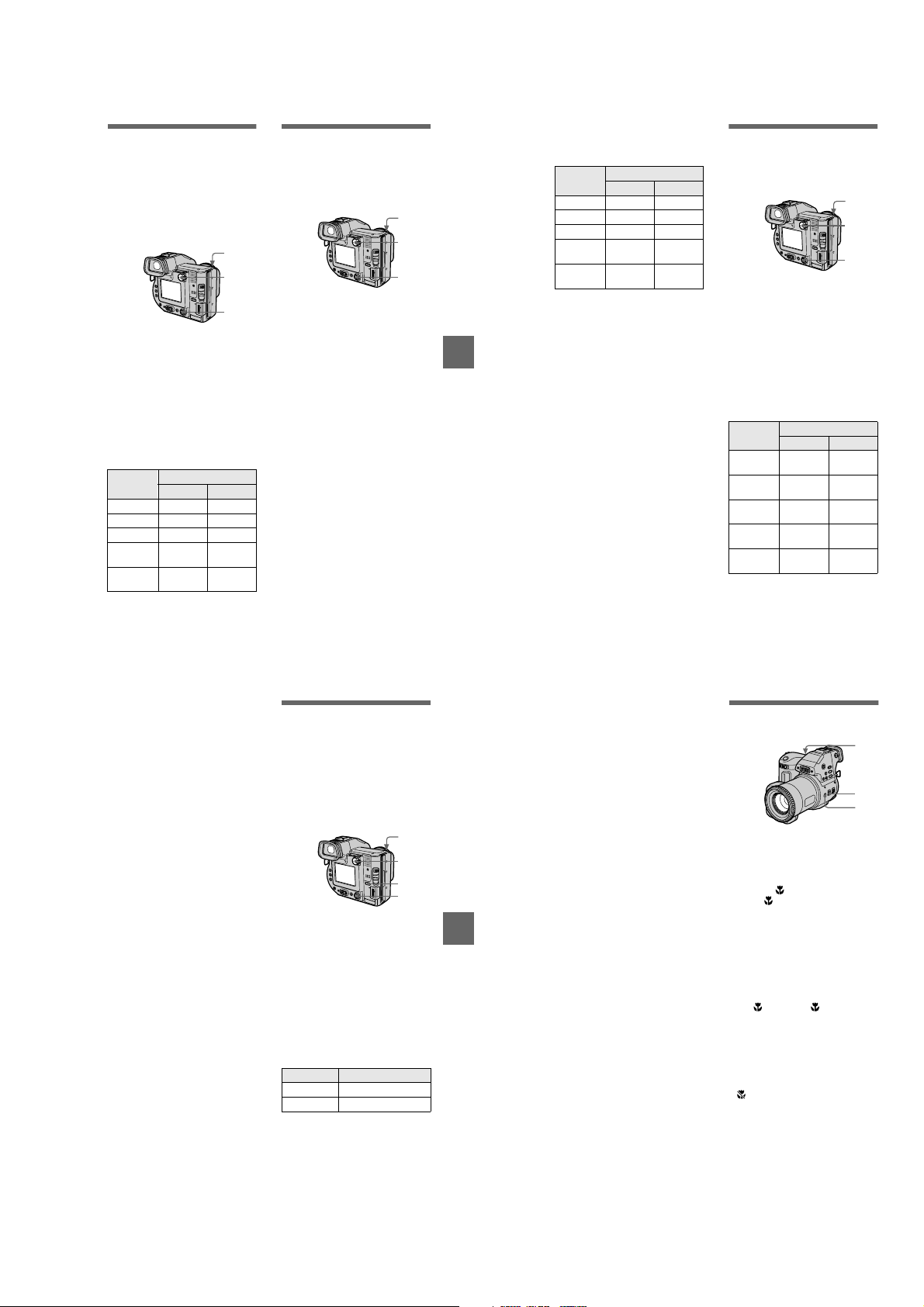
Recording still
images for e-mail (EMAIL)
TheE-MAILmoderecordsasmallsize (320×240) image at the same time
as a still image. Small-size images are
convenient for e-mail transmission,
etc. Images in E-MAIL mode are
recorded in the JPEG format.
3
1
2
Set the PLAY/STILL/MOVIE
1
selector to STILL.
Select [FILE], [REC MODE],
2
andthen[E-MAIL]fromthe
menu.
Record the image.
3
The number of images that you
canrecordonafloppydiskor
“Memory Stick” (8 MB) in E-MAIL
mode
Image size Number of images
1600×1200 Approx. 3 Approx. 8
1600 (3:2) Approx. 3 Approx. 8
1600 (ECM)
1024×768 Approx. 8 Approx.
T o re turn to normal
recording mode
Select [NORMAL] in step 2.
Floppy disk
Approx. 7 —
640×480 Approx.22Approx.
“Memory Stick”
20
44
Adding audio files to
still images (VOICE)
Images in VOICE mode are recorded
in the JPEG format, and audio is
recorded in the MPEG format.
3
1
2
Set the PLAY/STILL/MOVIE
1
selector to STILL.
Select [FILE], [REC MODE],
2
andthen[VOICE]fromthe
menu.
Record the image.
3
If you press and release the
shutter button, sound is
recorded for five seconds.
If you hold down the shutter
button, sound is recorded until
you release the shutter button for
up to 40 seconds.
51
The number of images that you
can record on a floppy disk or
“Memory Stick” (8 MB) in VOICE
mode
Image size Number of images*
1600×1200 Approx. 3 Approx. 7
1600 (3:2) Approx. 3 Approx. 7
1600 (ECM)
1024×768 Approx. 6 Approx.
∗ When recording 5-second audio.
To return to n ormal
recording mode
Select [NORMAL] in step 2.
BB
B Various recording
B
Floppy disk
Approx. 5 —
640×480 Approx.12Approx.
“Memory Stick”
17
34
Recording text
documents (TEXT)
Text is recorded in GIF format to
provide a clear image.
3
1
2
Set the PLAY/STILL/MOVIE
1
selector to STILL.
Select [FILE], [REC MODE],
2
and then [TEXT] from the
menu.
Record the image.
3
The number of images tha t you
can record on a floppy disk or
“Memory Stick” (8 MB) in TEXT
mode
Image size Number of images*
1600×1200 Minimum4Minimum
1600 (3:2) Minimum5Minimum
1600 (ECM)
1024×768 Minimum11Minimum
∗ The maximum number of recorda ble
images depends on the document
condition, such as the amount of t ext
portions.
640×480
Floppy disk
Minimum4—
“Memory Stick”
25
28
Minimum28Minimum
61
160
52
T o re turn to normal
recording mode
Select [NORMAL] in step 2.
Notes
• If thesub jectis not evenly illuminated, you
may be unable to record a clear image.
• Writing and reading data take more time
than normal recording.
Recording still
images as
uncompressed files
(TIFF)
This mode simultaneously records still
images in both TIF F format
(uncompressed) and JPEG format
(compressed) when using a “Memory
Stick.”
4
1
2
3
Set the PLAY/STILL/MOVIE
1
selector to STILL.
Set the MS/FD selector to MS.
2
Select [FILE], [REC MODE],
3
and then [TIFF] from the
menu.
Record the image.
4
The number of images that you
can record on a “Memory Stick”
(8 MB) in TIFF mode
Image size Number of images
1600×1200 1
1600 (3:2) 1
To return to n ormal
recording mode
Select [NORMAL] in step 3.
Notes
• JPEG images are re corded in the image
size selected by the [IMAGE SIZ E] menu
(page 48). TIFF images are recorded in
[1600×1200] size other than when [1600
(3:2)F] is selected.
• Writing data takes more time than in
normal recording.
Recording images in
macro
1
2
3
Set the PLAY/STILL/MOVIE
1
selector to STILL or MOVIE.
Set the FOCUS AUTO/
2
MANUAL switch to AUTO.
Press (macro).
3
The (macro) indicator appears
on the LCD screen or on the finder.
WiththezoomleversettotheW
side, youcan shoot a subject that is
BB
B Various recording
B
about 2 cm (13/16 inch) away from
the lens surface in macro mode.
To return to normal
recording mode
Press again. The indicator
disappears.
Notes
• You ca nnot record images in macro with
the following PROGRAM AE modes:
—Landscape mode
—Panfocus mode
• You cannot record images in macro if the
indicator appears.
53
54
1-13
Page 21
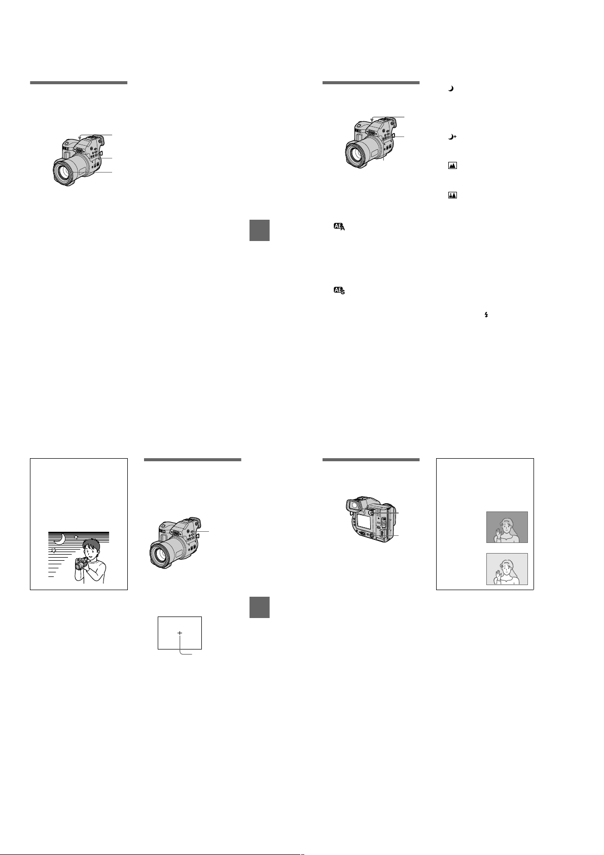
Focusing manually
Normally the focus is automatically
adjusted. This fun ction is useful whe n
the auto focus does not work well such
as in dark places.
1
2
3
Set the PLAY/STILL/MOVIE
1
selector to STILL or MOVIE.
Set the FOCUS AUTO/
2
MANUAL switch to MANUAL.
9
The
(manual focus) indicator
appears on the LCD screen or on
the finder.
Turn the focus ring to achieve
3
asharpfocus.
When you shoot still i mages, the
image on the LCD screen or on the
finder is enlarged (double* ) and
the focal point information appears
whilethefocusisbeingadjusted.
After adjusting, the image returns
to normal size. The range is from
2cm(13/16inch)to∞ (infinity).
∗ When using the digital zoom
function, the enlarged image w ill be
less than double size.
To reactivate auto focusing
Set the FOCUS AUTO/MANUAL
switch to AUTO.
Notes
• Focal point information may not
completely show the correct distance. Use
the information as a guide.
• Focal point information does not show the
correct distance when attaching the
conversion lens.
• If you shoot a subject within 0.8 m
(31 1/2 inches) whi le the zoom lever is set
to T side, you cannot get a clear focus. In
such cases, the focal point information
flashes. Move the zoom leverto the W side
until the indicator stops fl as hing.
• You cannot use th is function if you have
selected the Panfocus mode in the
PROGRAM AE function.
Using the PROGRAM
AE function
1
2
PROGRAM AE +/–
Set the PLAY/STILL/MOVIE
1
selector to STILL or MOVIE.
Press PROGRAM AE
2
repeatedly to select the
desired PROGRAM AE mode.
Aperture priority mode
For making the subject stand out
BB
B Various recording
B
against an unclear bac kground or
making both the subject and the
backgroundstand out clearly. Press
PROGRAM AE +/– repeatedly to
select an aperture value in 9 steps
from F2.8 to F 11.
Shutter speed priority
mode
For recording a sharp picture of a
fast-moving subject or recording
the flow of motion of a moving
subject.
Press PROGRAM AE +/–
repeatedly to select a shutter speed
in 17 steps from 8'' to 1/500 when
recording a still image, or in 11
steps from 1/8 to 1/500 w hen
recording a moving image.
Twilight mode
Suppresses the blurring of colors
of a bright subject in a dark place
so that you can rec ord the subject
without losing the dark atmosphere
of the surroundings.
Twilight plus mode
Increases the effectiveness of the
twilight mode function.
Landscape mode
Focusesonlyonadistantsubject
to record landscapes, etc.
Panfocus mode
Changes the focus quickly and
simply from a close sub ject to a
distant subject.
T o cancel PROGRAM AE
Press PROGRAM AE repeatedly until
the indicator on the L CD screen or on
the finder goes out.
Notes
• You can fo cus only on distant subjects in
Landscape mode.
• In Panfocus mode, the zoom position is set
to the W side and focus is fixed.
• When you record in Twilight plus mode,
we recommendthat you use a tripodto
prevent shaking.
• Set the forced flash when you use the
flash in the following modes:
– Twilight mode
– Twilight plus m ode
– Landscapemode
• You cannot use the PROGRAM AE
function when [REC MODE] is set to
[TEXT].
• If the setting is not appropriate in apertur e
priority mode and shutter spe ed priority
mode, the setting value indicator on th e
LCD screen or on thefinder flashes. Inthis
case, reset the value.
Tips
Under normal recording condition s, the
camera automatically makes various
adjustments, such as tho se for the focus,
iris, exposure, and white balance, as it
shoots. However, you may not be able to
carry out your desired shooting
depending on shooting conditions. The
program AE function provides you with
near-optimum adjustments to suit your
shooting situation.
Using the Spot lightmetering function
Select this mode when there is
backlight or when there is strong
contrast between the subject and the
background, etc.
SPOT
METER
Press SPOT METER to activate the
spot light-metering f unction. Position
the point you want to record at the spot
light-metering cross hair.
LCD screen/finder
Spot light-metering
cross hair
55
56
Adjusting the
exposure
(EXPOSURE)
1
2, 3
Set the PLAY/STILL/MOVIE
1
selector to STILL or MOVIE.
Select [CAMERA] and then
2
[EXPOSURE] from the menu.
Select the desired exposure
3
value.
Adjust the exposure value while
checking the brightness of the
BB
B Various recording
B
background. You can select values
ranging from +2.0 E V to -2.0 EV
in steps of 1/3 EV.
Note
If a subject is under extremely bright ordark
situations, or the flash is use d, the exposure
adjustment may not beeffective.
Tips
Normally, the camera automatically
adjusts the exposure. If the color of the
image is too dark or bright as ill ustrated
below, we recommend that you adjust the
exposure manually. When thecolor of the
image is too dark, set it toward +, and
when it is too bright, s et it toward –.
Set the exposure
toward +
Set the exposure
toward
–
57
58
1-14
Page 22
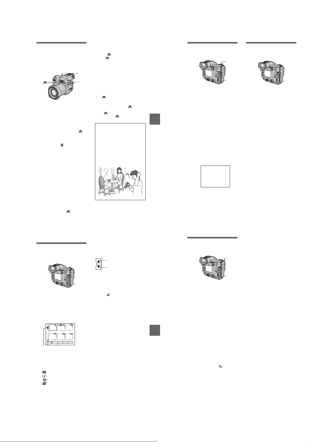
Adjusting the white
.
balance (WHITE
BALANCE)
Normally the white balance is
automatically adjusted.
Set the PLAY/STILL/MOVIE
1
selector to STILL or MOVIE.
Press WHITE BALANCE
2
repeatedly to select the
desired white balance
setting.
One-push white balance ( )
Adjusting the white balance
depending on the light source
OUT DOOR ( )
Recording a sun rise/sunset, nig ht
scene, neon signs, or fireworks
IN DOOR (n)
• Places where t he lighting
condition changes quickly
• Under bright lighting such as
photography studios
• Undersodiumormercurylamps
AUTO (No indicator)
Adjusts the white balance
automatically
To shoot in one-push white
balance mode
1
Press WHITE BALANCE
repeatedly until the indicator
appears.
2
Shoot a white object s uch as paper
full under the same situation you
will shoot.
3
Press .
The indicator flashes quickly.
When the white balance has been
adjusted and stored in the memory,
1
2
the indicator stops f lashing.
To reactivate auto adjustment
Select [AUTO] in step 2.
Note
• Select [AUTO] when shooting with
fluorescent lighting.
• The indicator means:
Slow flashing: white balance is n ot set.
Quick flashing: white bala nce is being
adjusted (after you pressed ).
Lit steady: w hite balance has been se t.
• If the indicator keeps flashing even
when you press , record in automatic
white balance mode.
Tips
The image is susceptibl e to lighting
conditions. The image looks blue un der
sunlight in the summer, and look s red
under mercur y lamps. Human eyes can
resolve these problems. However, the
camera cannot resolve the problem by
making adjustments. Norma lly, the
camera adjusts it automatically, but, if the
image appears in strange colors, we
recommend that you change the white
balance mode.
BB
B Various recording
B
59
Recording the date
and time on the still
image (DATE/TIME)
4
1
2, 3
Set the PLAY/STILL/MOVIE
1
selector to STILL.
Select [EFFECT] and then
2
[DATE/TIME] from the menu.
Select the date and time.
3
DAY & T IME
Imposes the date, hour, and
minute.
DATE
Imposes the year, month, and day.
OFF
Does not impose the date and time.
Record the image.
4
The date and time do not appear on
the LCD screen or on the finder
during shooting. These a ppear
during playback only.
2001 7 4
Notes
•
If you select [DATE] in step3, the date is
imposedonto the imagein the orderselected
with “Setting the date andtime” (page 14).
• The date and time are not imposed onto
Clip Motion images.
60
Enjoying picture
effects (PICTURE
EFFECT)
Set the PLAY/STILL/MOVIE
1
selector to STILL or MOVIE.
Select [EFFECT] and then
2
[P. EFFECT] from the menu.
Select the desired mode.
3
SOLARIZE
The light contrast is clearer and the
picture looks like an illustration.
B&W
The picture is monochrome (black
and white).
SEPIA
The picture is sepia-toned like an
old photograph.
NEG.ART
The color and brightness of the
picture are reversed as in a
negative.
OFF
Does not use the picture effect
function.
T o cancel picture effect
Select [OFF] in step 3.
1
2, 3
Various playback
B
Playing back six
images at once
(INDEX)
Set the PLAY/STILL/MOVIE
1
selector to PLAY.
Select [INDEX] on the LCD
2
screen or on the finder.
Six images are display ed at once
(index screen).
Only the first frame of Clip Motion
filesisdisplayed.
2001 7 4 12:30PMMVC-001F
DELETE
FILE SETUPTOOL
SELECT SINGLE DISPLAY
This shows the position of the
currently displayed im ages relative
to all the recorded images.
The following marks are displayed
on each image according to the
image type and settings.
:Movingimagefile
:VOICEmodefile
:E-mailfile
:Printmark
-
: Protect mark
TEXT: TEXT file
TIFF: TIFF file
CLIP: Clip Motion file
(No mark): Normal recording (no
settings)
To display the next
(previous) index screen
Selectv/Vat the lower-left on the
LCD screen or on the finder.
Displays the previous inde x
screen.
Displays the next index scre en
1
To return to normal playback
2
(single image)
• Select the desir ed image w ith the
control button.
• Select (Return).
Note
When viewing a n image recorded in C lip
Motion or TEXT mode on the INDEX
screen, the imag em ay appear different from
the actual image.
BB
B Various playback
B
Enlarging a part of the
still image (Zoom and
trimming)
Set the PLAY/STILL/MOVIE
1
selector to PLAY.
Displaytheimagetobe
2
enlarged.
Zoom in/out the image with
3
the zoom lever.
The zoom scaling indic ator
appears on the LCD screen or on
the finder.
Press the control button
4
repeatedly to select the
desired portion of the image.
: The image moves downward
v
: The image moves upward
V
: The image moves rightward
b
: The image moves leftward
B
3
1
2, 4
Notes
• You cannot trim moving images, still
images recorded in Clip Motion, TEXT
mode, or uncompressed images.
• Zoomscalingisupto5× regardless of the
original image size.
• The quality of enlarged images may be
deteriorated.
• The original data is lefteven if you enlarge
the image.
• The enlarged image is recorded as the
newest file.
To return to the normal size
Zoom out with the zoom lever until the
zoom scaling indicator ( ×1.1)
disappears from the screen, or simply
press the center
To record an enlarged image
(trimming)
1
Enlarge the image.
2
Press the shutter button. The image
is recorded at 640×48 0 size and the
image on the LCD screen or on the
finder returns to the normal size after
recording.
.
z
61
1-15
62
Page 23
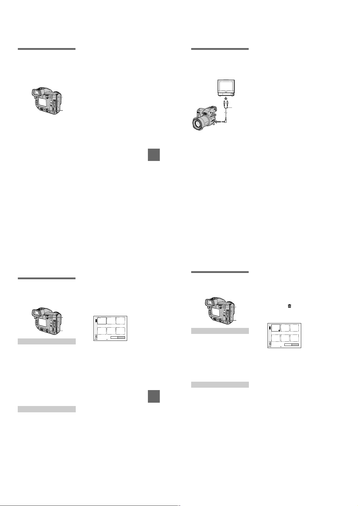
Playing back the still
images in order
(SLIDE SHOW)
This function is useful for checking the
recorded images or for presentations,
etc.
T o sk ip to th e ne x t/pre viou s
image during the slide show
Select\b/
LCD screen or on the finder.
Note
The interval setting time may vary
depending on the image size.
at the lower-left on the
B\
Viewing images on a
TV screen
Before connecting y our camera, be
sure to turn off the TV.
Set the TV/VIDEO
switch to
“VIDEO”.
Set the PLAY/STILL/MOVIE
1
selector to PLAY.
Select [FILE] and then [SLIDE
2
SHOW] from the menu.
Set the following items.
INTERVAL
You can select from 1 min (one
minute),30sec(30seconds),
10 sec (10 second s), 5 sec
(5 seconds), or 3 s ec (3 seconds).
REPEAT
ON: Plays back images in a
continuous loop (W hen using the
floppy disk, the slide show stops
approximately 20 minutes*) until
[RETURN] is selected.
OFF: After all images have been
played back, the sl ide show ends.
∗ The slide show does not end until all
the images are played back, even if it
takes more than 20 minutes.
Select [START].
3
The slide show begins.
To cancel the slide show
Select [CANCEL] in step 2 or 3.
1
2, 3
63
A/V
connecting
cable
to A/V OUT (MONO)
jack
Connect the A/V connecting
1
cable to the A/V OUT (MONO)
jack of your camera and to
the audio/video input jacks of
the TV.
BB
B Various playback
B
If your TV has stereo type input
jacks, connect the audio plug ofthe
A/V connecting cable to the Lch
jack.
Turn on the TV and start
2
playback on your camera.
The playback image appears onthe
TV screen.
Note
You cannot use a TV that has an antenna
(aerial) connector only.
64
Editing
B
Preventing accidental
erasure (PROTECT)
The-(protect) indicator appears on
protected images.
1
2, 3
In single mode
Set the PLAY/STILL/MOVIE
1
selector to PLAY, then
display the image to be
protected.
Select [FILE], [PROTECT],
2
and then [ON] from the menu.
The displayed image is protected
-
indicator appears.
and the
To release protection
Select [OFF] in step 2.
In INDEX mode
Set the PLAY/STILL/MOVIE
1
selector to PLAY, then
display the INDEX screen.
Select [FILE], [PROTECT],
2
and then [ALL] or [SELECT]
from the menu.
When you select [ALL]
3
Select [ON].
All the images in the floppy disk or
“Memory Stick” are protected.
When you select [SELECT]
Select all the images to be
protected with the co ntrol button,
then select [ENTER]. The selected
images are pro tected.
0001-0006/0040
ENTERPROTECT CANCEL
SELECT OK
To release protection
If you selected [ALL] in step 2, select
[OFF]. If you selected [SELECT] in
step 2, select the images to be
unprotected with the control button,
then select [ENTER].
BB
B Editing
B
Deleting images
(DELETE)
Protected images cannot be deleted.
1
2, 3
In single mode
Set the PLAY/STILL/MOVIE
1
selector to PLAY, then
display the image to be
deleted.
Select [DELETE] and then
2
[OK] from the menu.
The image is deleted.
In INDEX mode
Set the PLAY/STILL/MOVIE
1
selector to PLAY, then
display the INDEX screen.
Select [DELETE] and then
2
[ALL]or[SELECT]fromthe
menu.
When you select [ALL]
3
Select [ENTER].
All the unprotected images are
deleted.
When you select [SELECT]
Select all the images to be deleted
with the control button, then select
[ENTER]. The (delete)
indicator appears o n the selected
images and these images are
deleted.
0001-0006/0040
ENTERDELETE CANCEL
SELECT OK
T o cancel deleting
Select [CANCEL] in step 2 or 3.
Note
If there are files on the “Memory Stick”
with names having the same last 4 digits as
thefilenameoftheimagetobedeleted,
these files arealso deleted at the same time.
65
66
1-16
Page 24
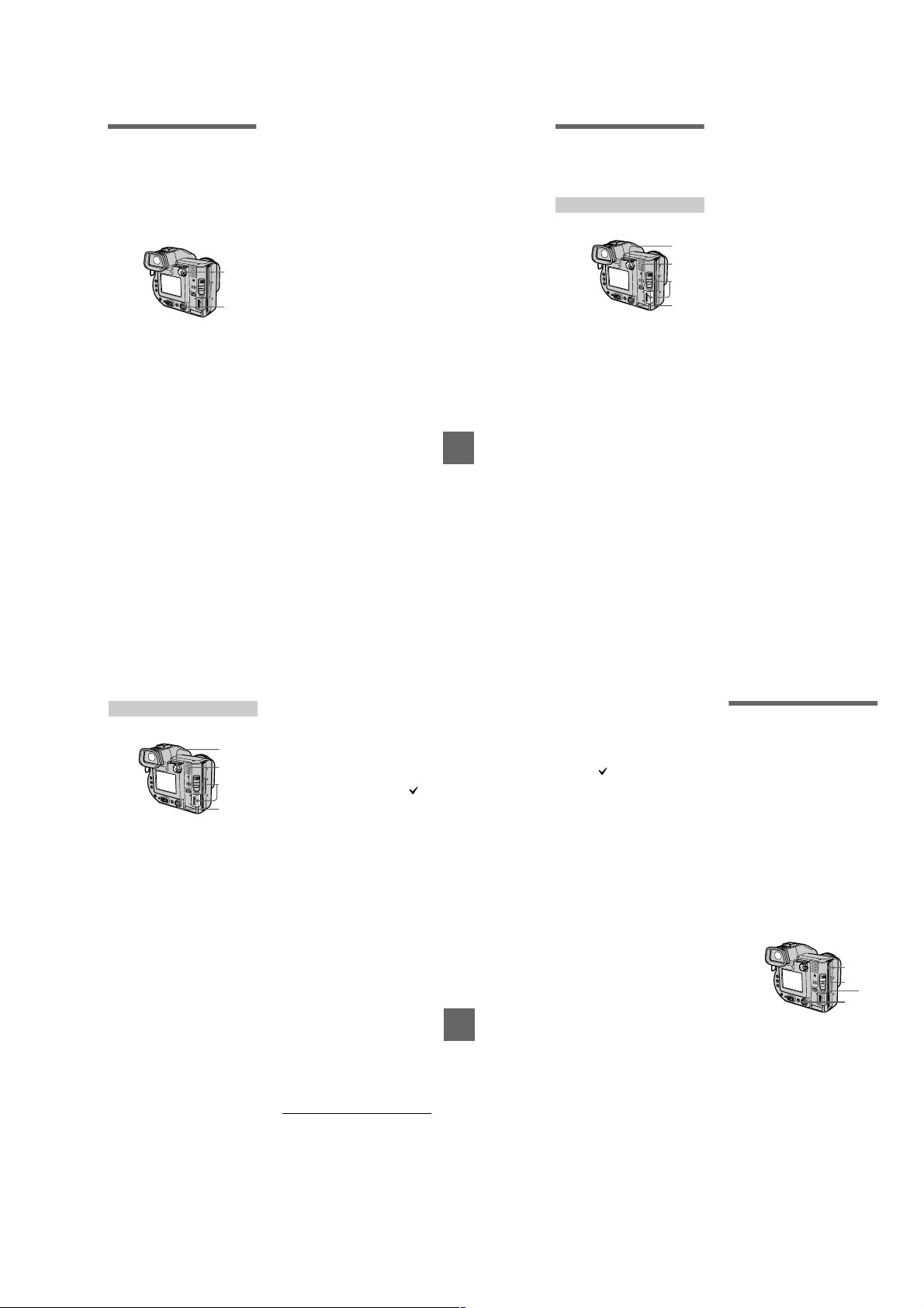
Changing the
recorded still image
size (RESIZE)
Use this function whe n you need a
small-size image to attach it to an Email. The original image is retained
even after resizing. The resized image
is recorded as the newest file.
1
2, 3
Set the PLAY/STILL/MOVIE
1
selector to PLAY, then
display the image of which
youwanttochangethesize.
Select [TOOL] and then
2
[RESIZE] from the menu.
Select the desired size .
3
• When the MS/FD selector is set
to FD
1600×1200, 1024×768, 640×480.
• When the MS/FD selector is set
to MS
1600 (FINE), 1024 (FINE),
640 (FINE).
The resized image is recorded,
then the display returns to the
image display before resizing.
To cancel changing the size
Select [CANCEL] in step 3.
Notes
• You cannot change the size of images
recorded in TEXT mode, moving images,
uncompressed images, or Clip Motion
images.
• When you change from a small size to a
large size, the pictur e quality deteriorates.
BB
B Editing
B
Copying images
(COPY)
Copies images to another floppy disk
or “Memory Stick.”
In single mode
2
1
5
3, 4
Select the media using the
1
MS/FD selector.
Set the PLAY/STILL/MOVIE
2
selector to PLAY, then
display the image to be
copied.
Select [TOOL], and then
3
[COPY] from the menu.
Select the media that the
4
image will be copied onto.
• When the MS/FD selector is set
to FD.
t FD: Copies to the floppy
FD
disk
FD
t MS: Copies to the
“Memory Stick”
• When the MS/FD selector is set
to MS.
MS
t MS: Copies to the
“Memory Stick”
MS
t FD: Copies to the floppy
disk
When you select [FD
t FD], the camera
[MS
automatically starts copying if the
floppy disk and “Memory Stick”
are inserted.
Insert or change the floppy
5
disk or “Memory Stick”
following the messages on
the LCD screen or on the
finder.
“RECORDING” appears. When
copying is completed,
“COMPLETE” appears.
To end copying, select [EXIT].
To continue copying the
image to other floppy disks
or “Memory Stick”s
After “COMPLETE” appears in step 5,
select [CONTINUE] and repeat step 5
above.
t MS] or
In INDEX mode
Select the media using the
1
MS/FD selector.
Set the PLAY/STILL/MOVIE
2
selector to PLAY, then
displaythe INDEX screen.
Select [TOOL], and then
3
[COPY] from the menu.
Select the media that the
4
image will be copied onto.
• When the MS/FD selector is set
to FD.
FD: Copies to the floppy
FD
t
disk
FD
t MS:Copies to the
“Memory Stick”
• When the MS/FD selector is set
to MS.
MS
MS: Copies to the
t
“Memory Stick”
MS
t FD: Copies to the floppy
disk
2
1
6
3, 4, 5
When you select [ALL]*
5
Select [OK].
∗ [ALL] can be selected only when
selecting [FD
MS].
When you select [SELECT]**
Select all the images to be copied
with the control button. The
mark appears on the selected
images and then select [ENTER].
∗∗When selecting [MS t FD], the
Insert or change the floppy
6
disk or “Memory Stick”
following the messages on
the LCD screen or on the
finder.
“RECORDING” appears. When
copying is completed,
“COMPLETE” appears.
Toend copying, select [EXIT].
To continue copying the
image to other floppy disks
or “Memory Stick”s
After“COMPLETE” appears in step 6,
select [CONTINUE] and repeat step 6.
When selecting [MS
amount of total images that will be
copied is too large to copy to one
floppy disk, the images will be copied
using multiple floppy disks.
t FD] or [FD t
necessary number of floppy disks
appears after selecting [ENTER].
Select [OK] again.
t FD], if the
To cancel copying partway
Select [CANCEL].
67
B Editing
68
Notes
• You cannot copy uncom pressed images.
• You cannot copy the i mage that is bigger
than 1.4 MB.
• You cannot copy the i mages that the total
amount of the images is bigger than
1.4 MB. If “NOT ENOUGH MEMORY”
appears or flashes on the INDEX
screen, cancel some images to copy and try
again.
• If you eject and insert the floppy disk or
“Memory Stick” without selecting [EXIT]
after “COMPLETE” appears, the image
will be copied.
• The number of floppy disks that is needed
for copying is as a guide, which is
displayed when selecting [MS
t FD].
Copying all the
information on your
floppy disk (DISK
COPY)
You can copy to another disk not only
the images you have recorded with
your camera but also various files you
have created in other software with
your computer.
Notes
• Once you carry out DISK COPY, all
information saved on the recipient floppy
disk is erased to be replaced by newly
written data including the protected image
data. Check the contents of the recipient
disk before copying the disk.
• Be sure to usethe floppy disk that has been
formatted by this camera to carryo ut
DISK COPY (page 72).
1, 4
3
1
2
Set the MS/FD selector to FD,
1
then insert the floppy disk to
be copied.
Select [FILE], [DISK TOOL],
2
[DISK COPY], and then [OK]
from the menu.
“DISK ACCESS” appears.
When “CHANGE FLOPPY
3
DISK” is displayed, eject the
floppy disk.
“INSERT FLOPPY DISK”
appears.
69
70
1-17
Page 25

Insert another floppy disk.
4
“RECORDING” appears. When
copying is completed,
“COMPLETE” appears.
To end copying, select [EXIT].
To continue copying to other
floppy disks
After “COMPLETE” appears instep 4,
select [CONTINUE] and repeatsteps 3
and 4 above.
To cancel copying partway
Select [CANCEL].
Note
If you eject and insert the floppy disk
without selecting [EXIT] after
“COMPLETE” appears, D ISK COPY will
be carried out onto the floppy dis k.
Selecting st ill im a ges
to print (PRINT MA RK)
You can mark a print mark on still
images recorded wit h your camera.
This mark is convenient when you
have images printed at a shop that
conforms with the DPOF (Digital Print
Order Format) standard.
1
2, 3, 4
In single mode
Set the PLAY/STILL/MOVIE
1
selector to PLAY and display
theimageyouwanttoprint.
Select [FILE], [PRINT MARK],
2
and then [ON] from the menu.
The (print) mark is marked on
the displayed image.
To unm ark the print mark
Select [OFF] in step 2.
In INDEX mode
Set the PLAY/STILL/MOVIE
1
selector to PLAY, then
display the INDEX screen.
Select [FILE], [PRINT MARK],
2
and then [SELECT] from the
menu.
Selecttheimagestobe
3
marked with the control
button.
BB
B Editing
B
Select [ENTER].
4
The marks on the selected
images change from green to
white.
0001-0006/0100
ENTERPRINT MARK CANCEL
SELECT OK
To unm ark selected print
marks
Select the images to be unmarked in
step 3 with the control button, then
select [ENTER].
To unmark all the print
marks
Select [FILE], [PRINT MARK],
[ALL],andthen[OFF]fromthemenu.
The marks on all images are
unmarked.
To print out using the FVP-1
Mavic a Printer
Set PRESET SELECT SW to PC on
the printer.
Notes
• You cannot mark m oving im ages, Clip
Motion images or images r ecorded in
TEXT mode.
• If you mark an image recorded in TIFF
mode with a print mark, on ly the
uncompressed image is printed, a nd the
JPEG image recorded at the sa me time is
not printed.
Format
When you format a floppy disk or
“Memory Stick,” all data stored on the
floppy disk or “Memory Stick” will be
deleted. Check the contents of the
floppy disk or “Memory Stick” before
formatting.
Note
Even if images are protected, these images
will be deleted.
1
2
3
Selectthefloppydiskor
1
“Memory Stick” using the
MS/FD selector.
Insert only the floppy disk or
2
“Memory Stick” you want t o
format.
Be sure to in sert only th e media
youwanttoformat.
Select [FILE] from the menu.
3
• When formatting a floppy disk
Select [DISK TOOL],
[FORMAT], and then [OK] from
the menu.
• When formatting a “Memory
Stick”
Select [FORMAT], and then
[OK] from the menu.
T o cancel formatting
Select [CANCEL] in step 3.
Notes
• Format the floppy disk or “Memory
Stick” only using this camera. You
cannot format the floppy disk or
“Memory Stick” using a computer
via the USB c able.
• When you format, be sure to use a fully
charged battery p ack or the AC power
adaptor as the power source.
As an external drive
B
Using the camera as
an external drive of a
computer
Once you connect the camera to a
computer using the US B cable, you
can use the camera as a floppy disk/
“Memory Stick” drive of a computer.
Install the USB driver to the computer
beforehand (page 31).
For Windows 98, Windows
98SE, Windows Me, and
Windows 2000 Professional
Users
Connect the camera to the
1
computer using the supplied
USB cable.
Select the drive type using
2
the MS/FD selector on this
camera.
When used as the floppy disk
drive, set the MS/FD select or to
FD.
When used as the “Memory Stick”
drive, set the MS/FD select or to
MS.
Connect the AC power
3
adaptor and turn on the
camera.
Open “My Computer” on
4
Windows and check the icon
“Removable Disk,” then use
the camera as an external
drive.
Note
When using Windows Me orWindows 2000
Professional, see also page 3 4.
71
73
72
Additional information
Precautions
On cleaning
Cleaning the LCD screen or finder
Wipe the screen su rface with a
cleaning cloth (not sup plied) or an
LCD cleaning kit (not supplied) to
remove fingerprints, dust, etc.
Cleaning the camera surface
Clean the camera surface with a soft
cloth slightly moistened with water,
then wipe the surface dry. Do not use
any type of solvent such as thinner,
alcohol or benzene as this may damage
the finish or the casing.
After using your camera at the
seashore or other dusty locations
Clean your camera c arefully.
Otherwise, the salty air may corrode
the metal fittings or dus t may enter the
inside of your camera, causing a
malfunction.
On floppy disks
To protect data recorded on floppy
disks, note the fol lowing:
• Avoid storing floppy disks near
magnets or magnetic fields such as
those of sp eakers and televisions .
Otherwise, permanent erasure ofdisk
BB
B As an external drive
B
data may result.
• Avoid storing floppy disks in are as
subject to direct su nlight or sources
of high temperature, such as a
heating device. Floppy disk warping
or damage may result, rendering the
disk useless.
• Avoid contact with the disk’ssurface
by opening the disk shutter plate. If
the disk’s surface become s
blemished, data may be rendered
unreadable.
• Avoid getting liquids on the floppy
disk.
• Be sure to use a floppy disk case to
ensure protection o f important data.
• Even when you u se a 3.5 inch 2HD
floppy disk, image data may not be
recorded and/or displa yed depending
on the using environment. In this
case, use a disk o f other brand.
On operating temperature
Your camera is designed for use
between the temperatures of 0°Cto
40°C(32°Fto104°F). Recordi ng in
extremely cold or hot places that
exceed this range is not r ecommended.
On moisture condensation
If the camera is brought directly from a
cold to a warm location, or is placed in
a very damp room, moisture may
condense inside or out side the camera.
Should this occur, the camera will not
operate properly.
Moisture condensation occurs
easily when:
• The camera is brought from a cold
location such as a s ki slope into a
warmly heated room.
• The camera is t aken from an air-
conditioned room or car interior to
the hot outdoors, etc.
How to prevent moisture
condensation
When bringing the camera f rom a cold
place to a warm place, seal the camera
in a plastic bag and allow it to a dapt to
conditions at the new location over a
period of time (abo ut an hour).
74
1-18
Page 26
If moisture condensation occurs
Immediately eject the floppy disk, then
turn off the camera and wait about an
hour for the moisture to evaporate.
Note that if you at tempt to record with
moisture remaining inside the lens, you
will be unable to record clear images.
On AC power adaptor
• Unplug the unit from the wall outlet
(mains) when you are not using the
unit for a long time. To disconnect
the power cord (m ains lead), pull it
out by the plug. Never pull the power
cord (mains lead ) itself.
• Do not operate the unit with a
damaged cord (mains lead) or if the
unit has been dropped or damaged.
• Do not bend t he power cord (mains
lead) forcibly, or place a heavy object
on it. This will dama ge the cord
(mains lead) and may cause fire or
electrical sh ock.
• Prevent metallic objects from coming
into contact with the metal parts of
the connecting section . If this
happens, a short may occur and the
unit may be damaged.
• Always keep metal contacts clean.
• Do not disassemble the unit.
• Do not apply mechanical shock or
drop the unit.
• While t he unit is in use, particularly
during charging, keep it away from
AM receivers and video equipm ent.
AM receivers and video equipm ent
disturb AM reception and video
operation.
• The unit b ecomes warm durin g use.
This is not a malfunction.
• Do not place the unit in locationsthat
are:
— Extrem ely hot or cold
— Dusty or dirty
— Very humid
— Vibrating
On battery pack
• Use only the spe cified charger with
the charging function.
• To prevent accident from a short
circuit, do not allow metal objects to
come into contact with the battery
terminals.
• Keep the battery pack away from fire.
• Never expose the battery pa ck to
temperatures above 60°C (140°F),
such as in a car parked in the sun or
under direct sunlight.
• Keep the battery pack dry.
• Do not expose the battery pack to any
mechanical shock.
• Do not disassemble nor modify the
battery pack.
• Attachthebatterypacktothecamera
securely.
• Charging while some capacity
remains does not affect the original
battery capacity.
On the built-in rechargeable
lithium battery
Your camera is supplied with a built-in
rechargeable lithium battery installed
so as to retain the date and time, etc.,
regardless of the setting ofthe POWER
switch. The built-in rechargeable
lithium battery is always charged as
long as you are using your camera. The
battery, however, will get discharged
gradually if you do not use your
camera.Itwillbecompletely
discharged in about six months if you
do not use your camera at all. Even if
the built-in rechargeable lithium
battery is not charged, it will not affect
the camera operation. To retain the
date and time, etc., charge the battery if
the battery is discharged.
75
Charging the built-in rechargeable
lithium battery:
• Connect your camera to house
current (mains) using the AC power
adaptor supplied with your camera,
and leave your camera with the
power turned off for more than 24
hours.
• Or install the fully charged battery
pack in your camera, and leave your
camera with the power turned off for
more than 24 hours.
If any problem occurs, unplug your
camera and contact your nearest Sony
dealer.
On “Memory Sticks ”
“Memory Stick” is a new compact,
portable and versatile IC recording
medium with a data capacity that
exceeds a floppy disk. “Memory Stick”
is specially designed for exchanging
Additional information
and sharing digital data among
“Memory Stick” compatible products.
Because it is removable, “Memory
Stick” canalsobeusedforexternal
data storage.
There are two types of “Memory
Sticks”: general “Memory Sticks” and
“MagicGate Memory Sticks” that are
equipped with the MagicGate*
copyright protection technology.
Youcanusebothtypesof“Memory
Stick” with your camera. However,
because your camera does not support
the MagicGate standards, data
recorded with your camera is not
subject to MagicGate copyright
protection.
∗ MagicGate is copyright protection
technology that uses encryption
technology.
Notes
• Do not remove the “Memory Stick” while
reading or writing data.
• Data may be damaged if:
—you remove the “Memory Stick” or turn
off your camera while reading or writing
data.
—you use the “Memory Stick” in a
location subject to the effects of static
electricity or noise.
• Do not attach any other material than the
supplied label on the labeling position.
• When you carry or store the “Memory
Stick,” put it in its supplied case.
• Do not touch the terminals of a “Memory
Stick” with your hand or a metal object.
• Do not strike, bend or drop the “Memory
Stick.”
• Do not disassemble or modify the
“Memory Stick.”
• Do not allow the “Memory Stick” to get
wet.
“Memory Stick”,,“MagicGate
Memory Stick” and are
trademarks of Sony Corporation.
“MagicGate” and are
trademarks of Sony Corporation.
Using your camer
a
abroad
Power sources
Youcan use your camera in any
country or area with the supplied
battery charger within 100 V to 240
VAC, 50/60 Hz.Use a commercially
availableAC plug adaptor [a],if
necessary, depending on the design of
the wall outlet (mains) [b].
AC-L10A/L10B/L10C
76
Watching the playback picture on
TV
If you want to view the playback
picture on a TV,you need a TV having
a video input jack and a video
connecting cable.
The color system of the TV must be
the same as that of your digital still
camera. Check the following list:
NTSC system
Bahama Islands, Bolivia, Canada,
Central America, Chile, Columbia,
Ecuador, Jamaica, Japan, Korea,
Mexico, Peru, Surinam, Taiwan,the
Philippines, the U.S.A., Venezuela,etc.
PALsystem
Australia, Austria, Belgium, China,
Denmark, Finland, Germany,Great
Britain, Holland, Italy, Kuwait,
Malaysia, New Zealand, Norway,
Portugal,Singapore, Spain, Sweden,
Switzerland,Thailand, etc.
PAL-Msystem
Brazil
PAL-Nsystem
Argentina, Paraguay, Uruguay
SECAM system
Bulgaria, Czech Republic, France,
Guiana, Hungary, Iran, Iraq, Monaco,
Poland, Russia, Slovak Republic,
Ukraine, etc.
About “InfoLITHIUM”
battery pack
What is the “InfoLITHIUM” battery
pack?
The “InfoLITHIUM” batterypackisa
lithium-ion battery pack that has
functions for communicating
information related to operating
conditions between your camera and
the AC power adaptor.
The “InfoLITHIUM” battery pack
calculates the power consumption
according to the operating conditions
of your camera, and displays the
remaining battery time in minutes.
Charging the battery pack
• Be sure to charge the battery pack
before you start using your camera.
• We recommend charging the battery
pack in an ambient temperature of
between 10°Cto30°C(50°Fto86°F)
until the POWER ON/OFF (CHG)
lamp goes out, indicating that the
battery pack is fully charged. If you
charge the battery pack outside of
this temperature range, you may not
be able to efficiently charge the
battery pack.
• After charging is completed, either
disconnect the AC power adaptor
from the DC IN jack on your camera
or remove the battery pack.
Additional information
Effective use of the battery pack
• Battery perfor mance decreases in
low-temperature surroundings. So,
the time th at the batt ery pack can be
used is shorter in cold places. We
recommend the following to use the
battery pack longer:
— Putthebatterypackinapocket
closetoyourbodytowarmitup,
and insert it in your camera
immediately before you start
taking shots.
— Usethelargecapacitybattery
pack (NP-F550, o ptional).
• Frequently using the LCD panel or
frequently operatin g the zoom wears
out the battery pack faster. We
recommend using the large capacity
battery pack (NP-F550, optional).
• BecertaintoturnthePOWERswitch
to off when not taking shots or
playingbackonyourcamera.
• We recommend have spare batteries
handy for two or thre e times the
expected shooting time, and make a
trial shots before taking the actual
shots.
• Do not expose the battery pack to
water. The battery pack is not waterresistant.
Remaining battery time indicator
• If the power goes off although the
battery remaining indicator indicates
that the battery pack has enough
power to operate, charge the battery
pack fully again so that the indication
on the battery remaining indicator is
correct. Note, however, that the
correct battery i ndication som etimes
will not be restored if it is used in
high temperatures for a long time or
left in a fully charged state, or the
battery pack is freq uently used.
Regard the remaining battery time
indication as the approximate
shooting time.
E
mark indicating there is little
• The
remaining battery time sometimes
flashes depending on the operating
conditions or am bient temperatu re
and environment even if the
remaining battery time is 5 to 10
minutes.
How to store the battery pack
• Even if the battery pack is not used
for a long time, store it in a dry, cool
place after fully charging it once per
year and then using t he battery pack
up on your camera. T his is to
maintain th e battery p ack’s functions.
• Tousethebatterypackuponyour
camera, leave the POWER switch to
on in PLAY mode until the power
goes off without a floppy disk or a
“Memory Stick” inserted.
Battery life
• The battery life is limited. Battery
capacity decreases little by little as
you use it more and more, and as
time passes. When the battery
operating time is shortened
considerably, a probable cause is that
the battery pack has r eached the end
of its life. Please buy a new battery
pack.
• The battery life varies according to
how it is stored and op erating
conditions and environment for each
battery pack.
77
78
1-19
Page 27
Troubleshooting
If you experience trouble with your camera, first check the following items. Should
your camera still not operate properly after you have made these checks, consult your
Sony dealer or local authorized Sony service facility. If code displays (C:
appear on the LCD screen or on the finder, the self-diagnosis display function is
working (page 87).
Symptom Cause and/or Solution
Your camera does not
work.
Your camera cannot
record images.
The picture is out of focus. • Your camera is not in macro recording mode when
The resizing function does
not work.
• You are not using an “InfoLITHI UM” battery pack.
t
Use an “InfoLITHIUM” battery pack (page 9).
• The floppy disk is not inserted properly.
t
Eject the disk, and insert it again (page 16).
• The battery level is too low. (The indicator
appears.)
t
Charge the battery pack fully (page 10).
• The AC power adaptor is not connected securely.
t
Connect it securely to the DC IN jack and a wall
outlet (mains) (page 1 0, 13).
• The malfunction occurs inside the camera.
t
Turn off the power, and turn on after one
minute, then check that the camera works
properly.
• The PLAY/STILL/MOVIE selector is set to PLAY.
t
Set it to STILL or MOVIE (pages 18, 25).
• No floppy disk is inse rted into your camera.
t
Insert a floppy disk (page 16).
• The tab on the disk is set to the unrecordable
position.
t
Set it to the recording position (page 16).
• No “Memory Stick” is inserted into your camera.
t
Insert a “Memory Stick” (pa ge 17).
• The write-protect switch on the “Memory Stick” is
set to LOCK.
t
Set it to the recording position.
you shoot a subject that i s about 3 to 25 cm
(1 3/16 to 9 7/8 inc hes) away from the lens.
t
Set the macro recordi ng mode (page 54).
t
Move the zoom lever to the W side.
• You cannot resize moving images, text images, Clip
Motion images, and uncompressed images.
ss
ss:ss
ss)
ssss
ssss
Symptom Cause and/or Solution
You cannot display a print
mark.
The picture is noisy. • Your camera is placed near a TV or other
The picture is too dark. • You are shooting a subject with a light source
The flash does not work. • The flash is set to .
Additional information
The date and time are
recorded incorr ectly.
Vertical streaks appear
when you are shooting a
very bright subject.
The zoom does not work. • PROGRAM AE is set to the Panfocus mode.
Digital zoom does not
function.
The image is in
monochrome.
The image cannot be
played back on a
computer.
• You cannot display print marks on moving images,
text images and Clip Motion images.
equipment that uses st rong magnets.
t
Move your camera away from the TV, etc.
behind the subject.
t
Adjust the exposure (page 58).
• The brightness of the LCD screen is too low.
t
Adjust the brightness of the LCD screen
(page 20).
t
Set the flash to (no indication), , or
(page 23).
• ThecameraisinoneofthefollowingPROGRAM
AE modes: Twilight, Twilight plus, or Landscape.
t
Cancel the PROGRAM AE function or set the
flash to (page 23, 56).
• The PLAY/STILL/MOVIE selector is set to
MOVIE.
t
Set it to STILL.
• The flash is n ot popped up.
t
Pop up the flash (page 23).
• The date and time are not set correctly.
t
Set the correct d ate and time (page 14).
• This is called the smear phenomenon.
t
This is not a malfunction.
t
Cancel the Panfocus m ode (page 56).
• You cannot use digital zoom when recording
moving pictures.
• Digital zoom is set to [OFF].
t
Set digital zoom to [ON] at the menu.
• You shot the image in TEXT mode.
t
Cancel the TEXT mode (page 52).
• The picture effect is set to B&W.
t
Cancel the B&W mode (page 60).
t
Consult the computer or software manufacturer.
Symptom Cause and/or Solution
The image and sound
break off when you play
back an image on a
computer.
Yourc amera cannot delete
an image.
The power turns off
suddenly.
The image does not
appear on the TV screen.
The slide show function
stops automatically.
You cannot use the
PROGRAM AE function.
The macro function does
not work.
• You are playing back the file from the floppy disk
or “Memory Stick.”
t
Copy the file to the hard disk of the computer
andthenplaybackthefilefromtheharddisk
(pages 29, 34).
• The image is protected.
t
Cancel the protection (p age 65).
• With the PLAY/STILL/MOVIE selector set to
STILL or MOVIE, if you do not operate the camera
for about three minutes while the power is on, the
camera turns off automatically to prevent wearing
down the battery pack.
t
Turn on the camera.
• The battery pack is discharged.
t
Replace it with a fully charged battery pack.
• The VIDEO OUT setting of your camera is
incorrect.
t
Change the setting (page 47).
• The slide show fu nction stops after abou t
20 minutes when usi ng a floppy disk.
t
To continue the slide show, select [START]
again (page 63).
• The camera is se t to TEXT mode.
t
Cancel the TEXT mode (p age 52).
• The camera is in manual focus mode.
t
Set it to auto focus mo de (page 55).
• PROGRAM AE is set to the Panfocus mode.
t
Cancel the Panfocus mode (page 56).
79
80
Symptom Cause and/or Solution
Your computer does not
recognize your c amera.
Additional information
Reinstall the USB driver when using Windows 98, Windows
98SE, Windows Me and Windows 2000 Professional
Turn on your computer and allow Windows to load.
1
Connect the USB jack on the camera and the computer with the
2
supplied USB cable.
Insert a media and set the MS/FD selec tor to the appropriate
3
position according to the media inser ted.
Connect the AC power adaptor to your camera and then to a w all
4
outlet (mains), and turn on the power of your camera.
• The battery level is low.
t
Use the AC power adaptor (page 13).
• The camera is turned off.
t
Turn on the camera.
• The USB cable is not connected firmly.
t
Disconnect the US B cable, and connect i t again
firmly. Make sure that “USB MODE” is
displayedontheLCDscreenoronthefinder
(page 31).
• The USB connectors on your computer are
connected to other equipment besides the keyboard,
the mouse, and your c amera.
t
Disconnect the US B cables except for the ones
connected to the keyboard, the m ouse, and your
camera.
• The position of the MS/FD selector is not set to the
proper position for the media being used.
t
Set the MS/FD selector to the proper position.
• The USB driver is not installed.
t
Install the USB dr iver (page 31).
• For Windows 98, Windows 98SE, Windows
Me and Windows 2000 Professional users
Since the camera is connected to a computer with
the USB cable before installing the USB driver, the
drive is not recognized properly by the computer.
t
Delete the drive which is not recognized
properly, then install the USBdriver. For details,
see the procedure be low.
81
82
1-20
Page 28
Open “Device Manager” on Windows.
5
For Windows 98, Windows 98SE and Windows Me users:
Open [Control Panel] from [ My Computer], then double-click [System].
1
System propert ies is displayed. Click th e [Device Manager] tab loc ated at the
2
top.
Click [ SonyDSC] in [ Other devices], then click the [Delete (E)]
3
button located at the lower-right corner.
For Windows 2000 Professional users:
* Log in with the permission of administrator.
Open [Control Panel] from [ My Computer], then double-click [System].
1
System properties is displayed. Click the [Hardware] tab located at the top,
2
then click the [Device Man ager (D)] button.
Click [View] in [Device Manager], then click [Devices by type (E)].
3
Right-click [ SonyDSC] in [ Other devices], then click [Delete (E)].
4
After the message appea rs to verify that you delete the device
6
manager, click the [OK] button.
Turn off the camera, disconnect the USB cable, and restart the
7
computer.
Install the USB driver in the supplied CD-ROM to the computer
8
following the procedure on page 31. Perform all steps without
skipping.
Battery packs
Symptom Cause and/or Solution
The battery pack cannot
be charged.
The battery life is short. • You are recording/pl aying back image s under
• The power of the camera is turned on.
t
Turn off the power of the came ra (page 10).
extremely cold tem peratures.
• The battery pack is not charged enough .
t
Charge the battery pack fully.
• The battery pack is dead.
t
Replace the battery pack with a new one.
Symptom Cause and/or Solution
The indication of the
battery remaining time is
not proper, or the power is
immediately turned off
even if the battery
remaining indicator
indicates that the batter y
level is sufficient.
The POWER ON/OFF
(CHG) lamp flashes when
charging a battery pack.
The POWER ON/OFF
(CHG) lamp does notlight
up when charging a
battery pack.
• You are using the camera for ma ny hours under
extremely hot or cold te mperatures.
• The battery pack is dead.
t
Replace the battery pa ck with a new one
(page 9).
• The battery level is too low.
t
Install the fully charged battery pack (page 9,
10).
• A deviation has occurred in the remaining battery
time.
t
Charge the battery pack fully ( page 10).
• A malfunctio n has occurred in the battery pack.
t
Contact your Sony dealer or local authorized
Sony service facility.
• The AC power adaptor is not connected.
t
Connect the power cord firmly to a wall outlet
(mains) (page 10).
• The battery pack is not installed properly.
t
Install it properl y (page 9).
• Charging of the battery pack is complete.
Additional information
Warning and notice messages
Various messages appear on the LCD screen or o n the finder. Check the
corresponding descriptions in the following list.
Message Meaning
DRIVEERROR Thereistroublewiththediskdrive.
SYSTEM ERROR Turn the power off and on again.
NO DISK No disk is inserted.
NO MEMORY STICK No “Memory Stick” is inserted.
FORMAT ERROR • The floppy disk loaded is not MS-DO S
MEMORY STICK ERROR The inserted “Memory Stick” cannot be
DISKPROTECT Thetabonthediskis settothe
MEMORY STICK LOCKED The write-protect switch on the
DISK FULL The disk is full.
NO MEMORY SPACE The capacity of the “Memory Stick” is
NO FILE No image is recorded on the disk.
FILE ERROR Trouble has occurred during pl ayback.
FILE PROTECT The image is protected.
DISK ERROR A 2DD floppy disk is inserted, or there is
DIRECTORY ERROR A directory with the same name already
NOT ENOUGH MEMORY The remaining capacity of the floppy
IMAGE SIZE OVER You tried to play back images with an
formatted (512 bytes
• Failed to format the “Memory Stick.”
• The Floppy Disk Adaptor for Memory
Stick is inserted.
used with your camer a, or the “Memory
Stick” is damaged or not inserted
correctly.
unrecordable p osition.
“Memory Stick” is set to the LOCK
position.
not sufficient to record image s.
trouble with the disk.
exists.
disk or “Memory Stick” is not enough to
copy the image.
image size larger than the maximum
playback size of this c amera.
×
18 sectors).
83
85
84
Message Me aning
INVALID OPERATION You are playing back a file that was
for “InfoLITHIUM” battery only
-
created on equipment other than your
camera.
The battery is not the “InfoLITHIUM” type.
The image is protected.
The battery level is too low. When the
remaining time is about 5 to 10 minutes,
E
may flash depending on the battery
pack used, operating conditions, or the
environment.
Additional information
86
1-21
Page 29
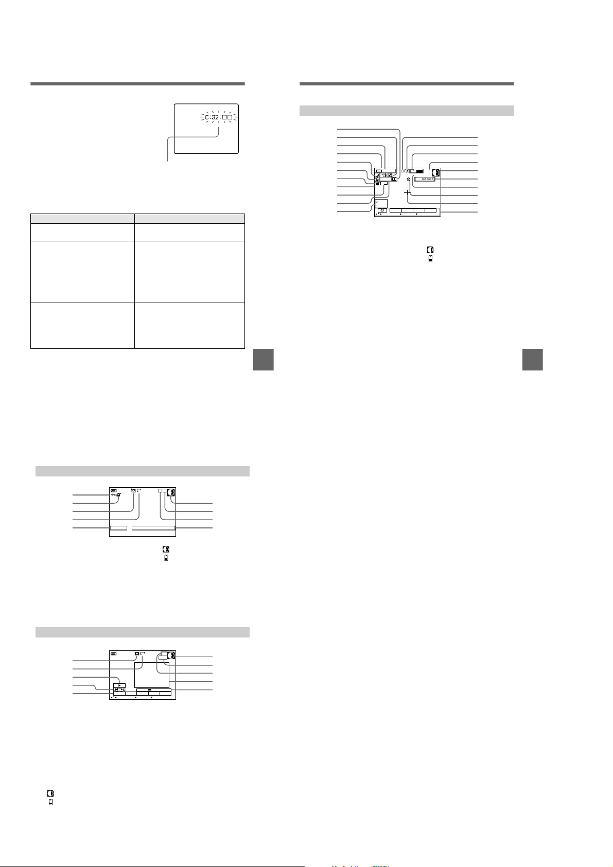
Self-diagnosis display
Your camera has a self-diagnosis display. This
function displays the c amera condition on the
LCD screen or on the finder with a combinatio n
of a letter and four digits of numbers. If this
appears, check the following code chart. The code
informs you of the camera’s current condition.
The last two digits (indicated by
depending on the state of the camera.
Code Cause and/or Corrective Action
C:32:
ss
C:13:
ss
E:61:
ss
E:91:
ss
If you are unable to rectify the problem even if you try corrective actions a
few times when C:
authorized Sony service facility.
ss:ss
) will differ
ss
Self-diagnosis display
• C:ss:
ss
You can repair the camera
yourself.
• E:
ss:ss
Contact your Sony dealer or local
authorized Sony servic e facility.
• There is trouble with the disk drive.
t
Turn the power off and on again.
• An unform atted floppy disk or
“Memory Stick” is inserted.
t
Format the floppy disk or “Memory
Stick.” (page 72)
• A floppy dis k or “Memory Stick” not
compatible with this camera is inserted.
t
Change the floppy disk or “Memory
Stick.” (pages 16, 17)
• A camera malfunction tha t you cannot
repair has occurred.
t
Contact your Sony deal er or local
authorized Sony service facility and
inform them of the 5-digit
indication. (example: E:61:10)
is indicated, contact your Sony dealer or local
LCD screen/finder indicators
The indicators during recording
1
2
3
4
5
6
7
8
9
0
qa
Sharpness indicator
A
Focus mode indicator/Macro
B
indicator
Battery remaining indicator
C
Flash level indicator/Flash
Additional information
D
mode indicator
PROGRAM AE indicator/Zoom
E
indicator
White balance indicator
F
SteadyShot indicator
G
Picture effect indicator
H
DATE indicator
I
EV level indicator
J
Iris/Shutter speed indicator
K
AE lock indicator/Focus lock
L
indicator
Recording mode/Clip Motion
M
indicator
Image size indicator
N
Number of recorded images
O
120min
+1.0EV
DATE
SOLARIZESOLARIZE
F2.8
500
EFFECT FILE SETU P
SELECT
10
ECM
1600
REC 0:03
15s
CAMERA
OK
MENU BAR OFF
Remaining disk capacity/
P
Remaining memory capacity
indicator
: Floppy disk
: “Memory Stick”
Recording time indicator
Q
Self-diagnosis function
R
indicator/Recording time
indicator
Self-timer indicator
S
Spot light-metering indicator
T
Menu bar and guide menu
U
They appear by pressing
control button and disappear by
pressing
qs
qd
qf
qg
qh
qj
qk
ql
w;
wa
Additional information
on the
v
.
V
The indicators during still image playback
1
2
3
4
5
Protect indicator/Zoom scaling
A
indicator
Print mark indicator
B
Recording mode/Clip Motion
C
indicator
Image size indicator
D
File name*
E
Remaining disk capacity/Remaining
F
memory capacity indicator
120min
MVC-011F
11/12
1600
12:00AM2001 7 4
Number of stored images on a
G
floppy disk or “Memory Stick”
Image number
H
Recording date of the playback
I
image*
∗ When the menu bar is displayed, this
indicator disappears from th e screen.
The indicators during moving image playback
1
2
3
4
5
Moving image file indicator
A
Image size indicator
B
Playback button/pause button
C
is displayed during s top, and
B
during playback.
Image searching buttons
D
Menu bar and guide menu
E
Remaining disk capacity/Remaining
F
memory capacity indicator
120min
DELETE
INDEX FILE SETUPTOOL
SELECT OK
X
6/8
160
0:10
MENU BAR OFF
Counter
G
Image number/number of
H
storedimagesonafloppydisk
or “Memory Stick”
Playback image
I
Playback bar
J
: Floppy disk
: “Memory Stick”
90
: Floppy disk
: “Memory Stick”
87
6
7
8
9
6
7
8
9
0
89
1-221-22 E
Page 30
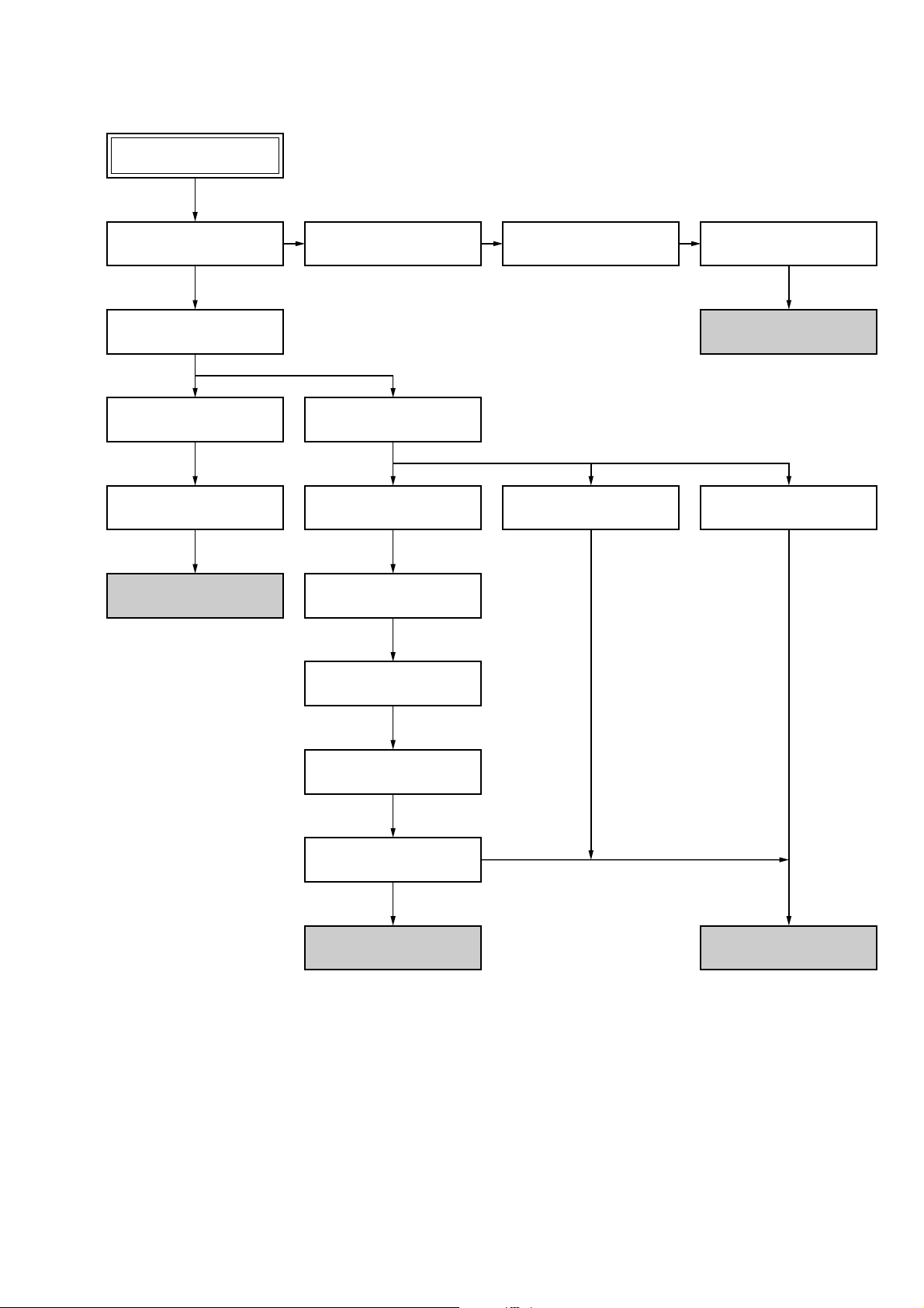
• This set can be disassembled in the order shown below.
MVC-FD97
MVC-FD97
SECTION 2
DISASSEMBLY
2-1. TOP CABINET BLOCK
ASSEMBLY (Page 2-2)
2-5. CABINET (REAR) BLOCK
ASSEMBLY (Page 2-3)
2-6. PK-55 BOARD
(Page 2-3)
2-7. LCD MODULE
(Page 2-4)
SERVICE POSITION
(PK-55 BOARD AND LCD PANEL)
(Page 2-4)
2-2. EVF BLOCK ASSEMBLY
(Page 2-2)
2-8. FDD BLOCK ASSEMBLY
(Page 2-5)
2-9. FU-153 BOARD
(Page 2-5)
2-10. LENS COMPLETE BLOCK
ASSEMBLY (Page 2-5)
2-11. CABINET VP BLOCK
ASSEMBLY (Page 2-5)
2-3. VF LENS ASSEMBLY
(Page 2-2)
2-14. FC-85 BOARD
(Page 2-7)
2-4. VF-143 BOARD
(Page 2-2)
SERVICE POSITION (EVF)
(Page 2-3)
2-15. CF-83 BOARD
(Page 2-7)
2-12. VP-55 BOARD
(Page 2-6)
2-13. LENS BLOCK ASSEMBLY
(Page 2-6)
SERVICE POSITION
(CD-311 AND VP-55 BOARDS)
(Page 2-6)
SERVICE POSITION
(FC-85 BOARD)
(Page 2-7)
2-1
Page 31

Note: Follow the disassembly procedure in the numerical order given.
2-1. TOP CABINET BLOCK ASSEMBLY
2 Screw
(M2)
8 Flexible board
(CN802)
1 Two screws
(M2)
4 Screw
(M2)
0 Flexible board
(CN301)
6 Clow
5 Screw
(M2)
3 Screw
(M2)
7 Top cabinet block assembly
9 Harness
(CN301)
2-3. VF LENS ASSEMBLY
2 VF cabinet assembly
4 VF lens assembly
3 Flexible board
(CN501)
1 Screw
(M2)
2-2. EVF BLOCK ASSEMBLY
1 Two plate screws
(M2)
2 Accessory shoe
3 Screw
(M2)
5 EVF block assembly
4 Screw
(M2)
2-4. VF-143 BOARD
1 Flexible board
(CN802)
8 Clow
6 Clow
9 VF-143 board
7 Two clows
2 Two clows
5 Two LCD cushions
4 BL illuminator
3 Clow
2-2
Page 32

[SERVICE POSITION (EVF)]
: Contacting surface
VF-143 board
VF lens assembly
AC IN
AC power
adaptor
CPC-12 jig
(J-6082-436-A)
2-5. CABINET (REAR) BLOCK ASSEMBLY 2-6. PK-55 BOARD
5 Cabinet (rear) block assembly
3 Screw
(M2)
Base
Adjustment remote
commander
2 Flexible board
(CN781)
1 Two screws
(M2)
4 Screw
(M2)
6 Flexible board
(CN802)
2 Two screws
(M2)
1 Harness
(CN702)
4 Screw
2-3
7 Six screws
5 Z shield case assembly
3 Flexible board
(CN901)
8 PK-55 board
6 Flexible board
(CN851)
Page 33

2-7. LCD MODULE
4 Speaker
1 Two screws
2 Two screws
3 BL fixed plate
6 LCD module
5 Cold cathode
fluorescent tube
[SERVICE POSITION (PK-55 BOARD AND LCD PANEL)]
: Contacting surface
Insulating sheet
LCD panel
Cold cathode
fluorescent tube
AC power
adaptor
AC IN
Cabinet (front)
block assembly
PK-55 board
FC-85 board
Base
Adjustment remote
commander
Base
CPC-12 jig
(J-6082-436-A)
2-4
Page 34

2-8. FDD BLOCK ASSEMBLY
4 FDD block assembly
2-10. LENS COMPLETE BLOCK ASSEMBLY
5 Harness
(CN004)
1 Harness
(CN003)
2-9. FU-153 BOARD
2 Two flexible board
(CN182, 401)
3 Two flexible board
(CN101, 183)
1 Four screws
(M2)
2 Remove the lens complete
assembly in the direction of
the arrow.
2-11. CABINET VP BLOCK ASSEMBLY
1 Harness
(CN002)
4 FU-153 board
2 Harness
(CN001)
3 Screw
(M2)
5 Flexible board
(MF block)
1 Screw
(M2)
3 Two clows
4 Cabinet VP block assembly
2 Screw
(M2)
2-5
Page 35

2-12. VP-55 BOARD 2-13. LENS BLOCK ASSEMBLY
2 Screw
(M2)
qd Screw
(M2)
qf VP-55 board
7 Two flexible board
(CN231, 235)
4 Clow
qs Screw
(M2)
9 Screw
(M2)
1 Screw
(M2)
6 Cabinet (LT)
5 Clow
qa VP fixed plate
3 Screw
(M2)
8 Flexible board
(CN232)
0 Screw
(M2)
3 Boss
1 Two screws
2 Boss
4 Lens block assembly
[SERVICE POSITION (CD-311 AND VP-55 BOARDS)]
: Contacting surface
AC IN
Cabinet (front)
block assembly
CD-311 board
VP-55 board
Lens block assembly
AC power
adaptor
Cabinet (LB) assembly
FC-85 board
FU-153 board
CPC-12 jig
(J-6082-436-A)
Adjustment remote
commander
PK-55 board
Cabinet (rear)
block assembly
Base
Base
Cabinet (VP) assembly
2-6
Page 36

2-14. FC-85 BOARD 2-15. CF-83 BOARD
Adjustment remote
commander
CPC-12 jig
(J-6082-436-A)
FU-153 board
FC-85 board
CF-83 board
VP-55
board
AC IN
AC power
adaptor
Top cabinet
block assembly
Cabinet (rear)
block assembly
Cabinet (VP) assembly
Cabinet (LB) assembly
Lens block assembly
FDD
: Contacting surface
2 Screw
(M2)
3 USB connector
7 FC-85 board
6 Claw
4 Three flexible
boards
(CN701, 702, 703)
1 Flexible board
(CN682)
5 Four screws
(M2)
1 Screw
3 CF-83 board
Note: When installing CF-83 board, connect two switches
(S402, 403) with two SS knobs.
(M2)
Two switches
(S402, 403)
Two SS knobs
2 Two claws
[SERVICE POSITION (FC-85 BOARD)]
2-7
Page 37

2-16. CIRCUIT BOARDS LOCATION
MA-404
(MIC AMP)
FU-153
(DC IN)
FLASH UNIT
VF-143
LCD DRIVE, TIMING
( )
GENERATOR, BACK LIGHT
AE-25
(CONTROL SWITCH)
FC-85
CAMERA PROCESS, CAMERA DSP, VIDEO,
MEMORY, LENS DRIVE, SH DSP, USB I/F,
MS SOCKET, FDD INTERFACE, FDD CONTROL,
( )
HI CONTROL, AUDIO, DC/DC CONVERTER
CD-311
(CCD IMAGER, STEADY SHOT SENSOR)
CF-83
(CONTROL SWITCH)
PK-54
MODE SWITCH, A/V OUT,
LCD DRIVE, TIMING GENERATOR,
( )
BACK LIGHT DRIVE
VP-55
(STEDY SHOT CONTROL)
2-8
Page 38

2-17. FLEXIBLE BOARDS LOCATION
FP-171
FP-174
FP-173
FP-177
FP-170
FP-169
FP-166
FP-172
FP-168
FP-335
FP-176
FP-175
ND801
LCD901
Lens assembly
VAP assembly
LCD902
Control switch block
2-9 E
Page 39

3-1. OVERALL BLOCK DIAGRAM
LENS
FILTER
ND
Y DRIVE A, B
P DRIVE A, B
M
VAP LOCK
SENSOR
VAP UNIT
VP-55 BOARD
CD-311 BOARD (1/2)
SE150, 151
PITCH/YAW
SENSOR
+
BT901
BATTERY
TERMINAL
S
–
J001
DC IN
IC203
VAP LOCK
MOTOR DRIVE
(SEE PAGE 4-41)
FU-153 BOARD
(SEE PAGE 4-68)
BATT SIG
05
FOCUS
SENSOR
VAP LOCK SENS
VAP LOCK ON
(SEE PAGE 4-41)
IC150
PITCH/YAW
SENSOR AMP
(SEE PAGE 4-9)
FLASH
UNIT
MM
IC201, 202
PITCH, YAW
DRIVE
ZOOM
SENSOR
STB CHARGE
XSTB FULL
STRB ON
STRB AIN
IC001
CONTROL
(SEE PAGE 4-35)
M
Z SENS RST
F SENS RST
DC
SECTION 3
BLOCK DIAGRAMS
CD-311 BOARD (1/2) FC-85 BOARD
IRIS
METER
M
H
(SEE PAGE 4-21)
IC205
AMP
(SEE PAGE 4-41)
IC208
A/D
CONVERTER
(SEE PAGE 4-42)
BL UNREG
ACV UNREG
ST UNREG
BATT UNREG
DRIVE +
ND DRIVE–
DRIVE–
HALL+
IC183
VAP P 5V
FDD P 5V
FDD 4.9V
CAM 15V
A 4.9V
PANEL 13.2V
PANEL 4.9V
PANEL –15.3V
PANEL 6.5V
D 3.2V
CAM 3.2V
CAM P 5V
D 1.8V
A 3.2V
CAM –7.5V
(SEE PAGE 4-42)
IC101
CCD IMAGER
(SEE PAGE 4-8)
IC181
ND FILTER DRIVE
(SEE PAGE 4-21)
IC184, 185
(SEE PAGE 4-21, 22)
IRIS DRIVE
HALL AMP
ZOOM MOTOR
DRIVE
FOCUS MOTOR
DRIVE
IC209
STEADY SHOT
CONTROL
CONTROL SWITCH BLOCK
(SEE PAGE 4-62)
AE-25
BOARD
(SEE PAGE 4-64)
CF-83
BOARD
(SEE PAGE 4-62)
D401
BATT
UNREG
ACV
UNREG
D402
CCD OUT
H1, H2
V1A, V1B, V2, V3A,
V3B, V4, VSUB CNT
IC182
IRIS
(MECHA SHUTTER)
DRIVE
(SEE PAGE 4-22)
HALL AD
HALL AD
CAM SI, CAM SO, XCAM SCK
ZOOM
SWITCH
SHUTTER
SWITCH
FUNCTION
KEY
FUNCTION
KEY
IC401
+3.1V REG
(SEE PAGE 4-31)
IC102
S/H, AGC,
A/D CONV.
(SEE PAGE 4-15)
IC101
TIMING
GENERATOR
(SEE PAGE 4-15)
IC186
EVR
(D/A CONVERTER)
(SEE PAGE 4-22)
PE EN1,
PE DIR1A, PE DIR1B
PE EN0,
PE DIR1A, PE DIR0B
VAP LOCK ON
VAP LOCK SENS
STRB ON
STRB AIN
MA-404 BOARD
ZOOM SW AD
XRS ON1, XRS ON2
KEY AD4
(SEE PAGE 4-62)
KEY AD0, KEY AD3
MSHUT ON
ND ON
PE DAC LEVEL
CNTC
SP VOL
Z SENS RST
F SENS RST
STB CHARGE
XSTB FULL
(1/2)
IC402
RESET
(SEE PAGE 4-31)
DATA BUS 12
CAM SO, XCAM SCKCAM SO, XCAM SCK
SP VOL
SYS DD ON
LCD DD ON
BATT SIG
1, 2
IC301
CAMERA
DSP
(SEE PAGE 4-18)
CAM SI, CAM SO, XCAM SCK
IC404
HI
CONTROL
(SEE PAGE 4-32)
16
14
IC505
16M
FLASH ROM
(SEE PAGE 4-25)
IC506
64M SDRAM
(SEE PAGE 4-25)
DATA BUS16 16
ADDRESS BUS14 14
Y OUT
C OUT
AU SDTI
AU SDTO
PANEL/EVF Y
PANEL/EVF R-Y
PANEL/EVF B-Y
EXT STRB ON
BEEP IN
IC651
X651
48MHz
EVF SENS
EVF LED ON
CLOCK GEN.
(SEE PAGE 4-26)
VF-143 BOARD (1/2)
(SEE PAGE 4-57)
KEY AD1, KEY AD2, XCAM/PB,
MOVIE/XSTILL, XPWR
HI SO, HI SI, XHI SCK
IC406
EEPROM
(SEE PAGE 4-32)
RST SIO, RST SCK
LANC IN
LANC OUT
16
20
16 16
12
ADDERESS BUS ADDERESS BUS
IC302
64M SDRAM
(SEE PAGE 4-20)
CAM SI, CAM SO, XCAM SCK
TG CLK
MC CLK
USB CLK
AU CLK
D501, Q501
EYE SENSOR
IC405
TIMER
CLOCK
(SEE PAGE 4-32)
IC403
LANC IN/OUT
(SEE PAGE 4-31)
LANC SIG
LANC DC
DATA BUS DATA BUS
IC508
EEPROM
(SEE PAGE 4-25)
HALL AD
SP VOL
HI SO, HI SI, XHI SCK
BEEP IN
HI SO, XHI SCK
HI SO, XHI SCK
MC CAM,
SH DSP
(SEE PAGE 4-23)
20
AUDIO AD/DA
CONVERETER
(SEE PAGE 4-33)
CONVERTER
(SEE PAGE 4-58)
VF-143 BOARD (2/2)
FUNCTION
CONVERTER
(SEE PAGE 4-49)
EXT STRB ON SENS
PK-55 BOARD (3/3)
IC501
IC252
IC503
D/A
(EVR)
KEY
IC902
D/A
(EVR)
BT701
LITHIUM
BATTERY
16
3
MC XRD
MC XWE1
BL LEV
USB DATA
V OUT ON
A OUT L
EVF Y
EVF R-Y
EVF B-Y
PANEL Y
PANEL R-Y
PANEL B-Y
(SEE PAGE 4-30)
Y OUT
C OUT
A IN L
IC702
FDD
CONTROL
MS DIO, MS BS, MS SCLK
IC681
USB I/F
(SEE PAGE 4-26)
IC901
VIDEO AMP
(SEE PAGE 4-19)
IC253
AUDIO AMP
(SEE PAGE 4-33)
IC502
DRIVE
(SEE PAGE 4-57)
IC601
DC/AC CONVERTER
(SEE PAGE 4-59)
IC901
DRIVE
(SEE PAGE 4-50)
BL UNREG
IC851
DC/DC CONTROL
(SEE PAGE 4-53)
FDD DATA
LCD
LCD
REC/PB AMP,
(SEE PAGE 4-27)
D+ USB D+
D– USB D–
SWITCHING
Q856
SWITCHING
FP-176 FLEXIBLE
BOARD
IC704
STEPPING
MOTOR
DRIVE
FDD DATA
PK-55 BOARD (1/3)
IC702
SHOCK DETECT
(SEE PAGE 4-47)
FP-335 FLEXIBLE
BOARD
(SEE PAGE 4-26)
PK-55 BOARD (2/3)
(SEE PAGE 4-47, 48)
VIDEO OUT
AUDIO OUT
SP+, SP–
MA-404 BOARD (2/2)
IC301
MIC AMP
(SEE PAGE 4-62)
IC603
LCD TIMING
GENERATOR
(SEE PAGE 4-60)
Q605
T601
IC904
LCD TIMING
GENERATOR
(SEE PAGE 4-51)
T851
INVERTER
TRANS
(SEE PAGE 4-48)
CN681
VR
VG
VB
VR
VG
VB
BL HIGH
FLOPPY
MS
SOCKET
AV OUT
DISK
DRIVE
UNIT
CN201
USB
J781
MIC901
MICROPHONE
LCD902
COLOR
LCD
MONITOR
ND601
LCD901
COLOR
LCD
MONITOR
SP901
SPEAKER
ND801
ACC
MVC-FD97
3-1 3-2
Page 40

MVC-FD97
3-12. POWER BLOCK DIAGRAM 1
J001
DC IN
BT901
BATTERY
TERMINAL
+
S
–
FU-153 BOARD FC-85 BOARD (1/2)
(SEE PAGE 4-68)
CN001
ACV UNREG
1
BATT/XEXT
3
ACV GND
2
CN002
BATT
UNREG
1
BATT SIG
2
DC PACK SW
4
BATT GND
3
Q001, 004
Q002, 003
Q005
CHARGE
CONTROL
PK-55 BOARD (1/2)
(SEE PAGE 4-47)
BT701
LITHIUM BATTERY
CN004
F003
F001
F002
F005
F004
CN003 (1/2) CN002 (1/2)
CN701 (1/2) CN801 (1/2)
CN001
6
6
7
2
3
4
5
1
8
3
4
2
1
5
150
BL UNREG
7
ST UNREG
2
3
VCC UNREG
4
5
ACV UNREG
1
BATT UNREG
8
FAST CHARGE ON
3
INIT CHARGE ON
4
2
1
5
BATT
DC PACK SW
BATT UNREG
BATT/EXT
BATT SIG
D401
D402
IC401
(SEE PAGE 4-31)
+3.1V
REG
32
D410
Q404
IC402
RESET
(SEE PAGE 4-31)
IC405
TIMER
CLOCK
(SEE PAGE 4-32)
IC404
HI CONTROL
(SEE PAGE 4-32)
BACKUP
VCC
XLANC ON
IC403
LANC I/O
(SEE PAGE 4-31)
42 45
75 – 77
86 87
10
V REF 2.5V
BL UNREG
ST UNREG
L001
18 45
6
11
VCC OUT
VCC
–INA
IC001
DC CONTROL
(SEE PAGE 4-35)
–INB
VCC UNREG
ACV UNREG
OUT A
+IN A
SCP A
OUT B
+IN B
SCP B
CN801 (2/2)
EVER 3.2VEVER 3.2V
26
42
BL UNREG
A 4.9V
D 3.2V
BL UNREG
ST UNREG
FDD P 5V
CAM 15V
CAM –7.5V
A 4.9V
CAM P 5V
FDD 4.9V
41
39
37
36
40
19
20
38
TO
POWER BLOCK 3
A
(SEE PAGE 3-27)
TO
POEWR BLOCK 2
B
(SEE PAGE 3-25)
PANEL 13.2V
PANEL –15.3V
PANEL 6.5V
PANEL 4.9V
PANEL 3.2V
Q004
SWITCHING
46
7
8
Q001
SWITCHING
44
12
13
Q003
SWITCHING
L007
T001
DC/DC CONV.
TRANS
4
3
2
1
L005
Q009, 010, 014
EMERGENCY
5
6
8
4.9V
DETECT
Q013, 016
LCD DD ON
D002
RECT
D001
RECT
LCD DD ON
–15V
L016
D003 D004
Q025, 028,
Q031, 034
–7.5V
REG
Q023
Q024, 032
Q036, 038
13.2V
REG
SWITCH
Q027, 030, 037
PANEL 6.5V
REG
Q026, 029, 035
PANEL –15.3V
REG
PANEL
4.9V
L009
L015
L012
OUT C
–IN C
SCP C
OUT D
–IN D
SCP D
40
26
24
Q002
SWITCHING
39
31
29
16
RT
CT
1729
L004
3.2V
Q005 – 007
D1.8V
REG
LCD DD ON
CAM DD ON
VREF 2.5V
EVF DD ON
L008
L010
L011
Q018
Q017, 019
L014
L018
Q020, 021, 022
EVF 12V
REG
CAM 3.2V
CAM DD ON
CN182
D 3.2V
A 4.9V
VAP P 5V
CAM DD ON
CN802
D 3.2V
EVF BL 4.75V
BL UNREG
EVF 12V
EVF 3.1V
D 1.8V
D 3.2V
A 3.2V
12
5
3
4
14
6
7
24
10
11
12
13
TO
POWER BLOCK 3
C
(SEE PAGE 3-27)
TO
POWER BLOCK 2
D
(SEE PAGE 3-25)
+INC
25
BATT UNREG
FAST CHARGE ON
INIT CHARGE ON
BATT/EXT
Q409
BATT SIG
DC PACK SW
05
BATTERY
CHARGE
DETECTOR
71
BATT SENS
100
FAST CHARGE
27
INIT CHARGE
20
BATT/XEXT
48
BATT SI
49
BATT SO
65
CHARGE INH
SYS DD ON
LCD DD ON
EVF DD ON
+IND
30
V REF 2.5V
19
POW CONT
20
CTL B
21
CTL C, D
22
VREF 2.5V
47
25CAM DD ON
99
3-23 3-24
Page 41

3-13. POWER BLOCK DIAGRAM 2
MVC-FD97
POWER BLOCK 1
(SEE PAGE 3-24)
FC-85 BOARD (2/2)
POWER BLOCK 1
(SEE PAGE 3-24)
VF-143 BOARD
CN501
D 3.2V
14
15
EVF 3.1V
16
EVF 12V
TO
17
18
D
21
EVF BL 4.75V
22
BL UNREG
4
D501
(EYE SENSOR LED)
FDD P 5V
D 3.2V
D 1.8V
A 3.2V
A 4.9V
TO
B
BL UNREG
FDD 4.9V
CAM 15V
CAM –7.5V
CAM DD ON
CAM P 5V
CAM 3.2V
IC504
SHOCK
DETECT
(SEE PAGE 4-57)
L502
L255
FDD P 5V
L501
Q253
IC503
EVR
(D/A CONVERTER)
(SEE PAGE 4-58)
L503
IC502
LCD
DRIVER
(SEE PAGE 4-57)
IC253
AUDIO AMP
(SEE PAGE 4-33)
L252
Q102 – 105
L504
L602
L601
AUDIO DA/AD
CONVERTER
(SEE PAGE 4-33)
L254
LCD TIMING
GENERATOR
(SEE PAGE 4-60)
Q602, 603
IC252
L253
L184
IC603
CONVERTER
(SEE PAGE 4-59)
L604 L605
(SEE PAGE 4-26)
FB651
CH 3.2V
(SEE PAGE 4-21)
(SEE PAGE 4-60)
IC601
DC/AC
IC651
CLOCK GEN.
IC184
IRIS
DRIVE
IC604
NOR
(SEE PAGE 4-59)
T601
INVERTER
TRANS
L303
IRIS DRIVE
HALL AMP
HALL BIAS/GAN
CONTROL
(SEE PAGE 4-22)
IC602
AMP
IC301
CAMERA
DSP
(SEE PAGE 4-18)
FB301
IC185
CN601
STB
EVF 12V
ND601
BACK
LIGHT
IC302
64M SDRAM
(SEE PAGE 4-20)
FB302
FB304
IC186
EVR
(D/A CONV.)
(SEE PAGE 4-22)
5
1
(SEE PAGE 4-32)
A 3.2V
CAM DD ON
CAM 15V
CAM -7.5V
CAM P 5V
CAM 3.2V
(SEE PAGE 4-15)
LCD902
COLOR
MONITOR
IC406
EEPROM
IC102
S/H, AGC,
A/D CONV.
LCD
IC901
VIDEO AMP
(SEE PAGE 4-19)
FDD P 5V
ST UNREG
BL UNREG
FDD 4.9V
L101
GENERATOR
(SEE PAGE 4-15)
D501
ACCESS
D 3.2V
D 1.8V
A 4.9V
IC101
TIMING
IC508
EEPROM
(SEE PAGE 4-25)
L181
IC181
ND FILTER
DRIVE
(SEE PAGE 4-21)
IC505
16M
FLASH
(SEE PAGE 4-25)
IC501
MC CAM,
SH DSP
(SEE PAGE 4-23)
L502
(SEE PAGE 4-25)
FB503
IC502
NAND GATE
(SEE PAGE 4-23)
D 3.2V
IC183
FOCUS/ZOOM
MOTOR DRIVE
(SEE PAGE 4-21)
IC506
16M
SDRAM
FB501
IRIS(MECHA
SHUTTER)
(SEE PAGE 4-22)
IC182
DRIVE
CN402
A 4.9V
D 3.2V
D 3.2V
D 3.2V
6 5
10
FDD P 5V
BL UNREG
CAM –7.5V
Q182
FDD 4.9V
Q317, 318
CN301
1
L702
(SEE PAGE 4-30)
CAM
–7.5V
12
CAM 15VCAM 15V
11
CAM P 5V
F SENS VCC
Z SENS VCC
IC301
MIC AMP
(SEE PAGE 4-62)
D 3.2V
IC681
USB I/F
(SEE PAGE 4-26)
FB681
IC702
FDD
CONTROL
Q701 – 704
CD-311 BOARD (1/2)
CN101CN101
CAM –7.5V
12
CAM 15V
11
CN184
ND DRIVE+
12
F SENS VCC
14
Z SENS VCC
8
CONTROL SWITCH BLOCKMA-404 BOARD
(SEE PAGE 4-62)
CN303
4
Q681, 682
IC703
INVERTER
(SEE PAGE 4-30)
IC704
REC/PB AMP
STEPING
MOTOR DRIVE
(SEE PAGE 4-27)
(SEE PAGE 4-8)
STUNREGST UNREG
IC101
CCD
IMAGER
ND FILTER
MM
MOTOR
FOCUS
SENSOR
ZOOM
SENSOR
CN681
CN701
CN702
CN703
CN301
A 4.9V
RV001
ZOOM
TW
MS
3
SOCKET
9
9
10
5
FLOPPY
DISK
DRIVE
UNIT
5
3
4
FLASH
UNIT
8
05
3-25 3-26
Page 42

MVC-FD97
3-14. POWER BLOCK DIAGRAM 3
TYPE S/C model:
Please refer to page 6 to
discriminate the type of LCD.
TYPE C TYPE S
POWER BLOCK 1
(SEE PAGE 3-24)
PK-55 BOARD (2/2)
CN701 (2/2)
PANEL 13.2V
12
PANEL –15.3V
14
PANEL 6.5V
15
PANEL 3.2V
31
D 3.2V
13
PANEL 4.9V
11
TO
L901
L902
L903
L701
L801
D903
L802
VGH
VSS
VCC
VSH
VSH
CN901
1
9
3
12
2
PANEL
UNIT
LCD901
COLOR
LCD
MONITOR
L801
L802
D903
VGH
VGL
VREFH
VDD
VSH
CN901
1
3
2
23
24
PANEL
UNIT
LCD901
COLOR
LCD
MONITOR
A
25
32
9
10
EVER 3.2V
A 4.9V
BL UNREG
(SEE PAGE 4-50)
IC852
CURRENT
DETECT
IC802
LCD
DRIVE
(SEE PAGE 4-53)
IC702
SHOCK
DETECT
(SEE PAGE 4-47)
D702
CHARGE
D701
FLASH
D703
POWER
L851 L852 L853
D/A CONVERTER
(SEE PAGE 4-49)
Q854, 856
SWITCHING
IC801
(EVR)
(SEE PAGE 4-54)
BUFFER
(SEE PAGE 4-49)
IC851
DC/DC
CONTROL
IC803
Q861Q851, 852
(SEE PAGE 4-51)
T851
INVERTER
TRANS
IC902
COM AMP,
VCO
D854
LED
IC901
LCD TIMING
GENERATOR
(SEE PAGE 4-51)
CN851
IC801
D/A CONVERTER
(EVR)
(SEE PAGE 4-49)
10
ND801
BACK
LIGHT
IC802
LCD
DRIVE
(SEE PAGE 4-50)
IC803
BUFFER
(SEE PAGE 4-49)
IC902
COM AMP,
VCO
(SEE PAGE 4-51)
IC901
LCD TIMING
GENERATOR
(SEE PAGE 4-51)
POWER BLOCK 1
(SEE PAGE 3-24)
VP-55 BOARD
CN236
D 3.2V
12
A+4.9V
5
TO
C
VAP P 5V
3
CAM DD ON
4
05
L207
Q211, 208
L205
L206
IC208
A/D CONVERTER
(SEE PAGE 4-42)
L201
(SEE PAGE 4-41)
STEADY SHOT
(SEE PAGE 4-42)
IC201
YAW
DRIVE
Q205, 206
IC209
CONTROL
(SEE PAGE 4-41)
(SEE PAGE 4-42)
IC202
PITCH
DRIVE
Q209, 210
IC210
INVERTER
Q203, 204
IC204
DAMP
CONTROL
(SEE PAGE 4-41)
IC205
AMP
(SEE PAGE 4-41)
Q201, 202
PROTECT
L204
IC206
IC207
INVERTER
(SEE PAGE 4-42)
IC203
VAP LOCK
MOTOR DRIVE
(SEE PAGE 4-41)
CN232
CN231
CN234
A+4.9V
D 3.2V
S+3.2V
VAP
UNIT
MANUAL
FOCUS
BLOCK
3
5
5
6
CD-311 BOARD (2/2)
CN102
3
5
L150
IC150
PITCH/YAW
SENSOR AMP
(SEE PAGE 4-9)
SE150
PITCH
SENSOR
SE151
YAW
SENSOR
3-28 E3-27
Page 43

SECTION 4
PRINTED WIRING BOARDS AND SCHEMATIC DIAGRAMS
THIS NOTE IS COMMON FOR WIRING BOARDS AND SCHEMATIC DIAGRAMS
(In addition to this, the necessary note is printed in each block)
MVC-FD97
(For printed wiring boards)
• b: Pattern from the side which enables seeing.
(The other layers’ patterns are not indicated)
• Through hole is omitted.
• Circled numbers refer to waveforms.
• There are a few cases that the part printed on diagram
isn’t mounted in this model.
• Chip parts.
Transistor Diode
5
C
5246
EB
654
123
31
21
12
21321321
345
543
12
3
43
(For schematic diagrams)
• All capacitors are in µF unless otherwise noted. pF : µ
µF. 50 V or less are not indicated e xcept for electrolytics
and tantalums.
• Chip resistors are 1/10 W unless otherwise noted.
kΩ=1000 Ω, MΩ=1000 kΩ.
• Caution when replacing chip parts.
New parts must be attached after removal of chip.
Be careful not to heat the minus side of tantalum
capacitor, Because it is damaged by the heat.
• Some chip part will be indicated as follows.
Example C541 L452
22U 10UH
TA A 2520
(Measuring conditions voltage and waveform)
• Voltages and waveforms are measured between the
measurement points and ground when camera shoots
color bar chart of pattern box. The y are reference v alues
and reference waveforms. *
(VOM of DC 10 MΩ input impedance is used)
• Voltage v alues change depending upon input impedance
of VOM used.)
1. Connection
Pattern box
Front side of the lens
1.5m
2. Adjust the distance so that the output waveform of Fig.
a and the Fig. b can be obtain.
Kinds of capacitor
Temperature characteristics
External dimensions (mm)
• Constants of resistors, capacitors, ICs and etc with XX
indicate that they are not used.
In such cases, the unused circuits may be indicated.
• Parts with ★ differ according to the model/destination.
Refer to the mount table for each function.
• All variable and adjustable resistors have characteristic
curve B, unless otherwise noted.
• Signal name
XEDIT→ EDIT PB/XREC → PB/REC
• 2: non flammable resistor
• 1: fusible resistor
• C: panel designation
• A: B+ Line *
• B: B– Line *
• J : IN/OUT direction of (+,–) B LINE. *
• C: adjustment for repair. *
• Circled numbers refer to wa veforms. *
* Indicated by the color red.
Note : The components identified by mark 0 or
dotted line with mark 0 are critical for safety.
Replace only with part number specified.
H
Yellow
Cyan
White
Magenta
Green
AABBA=B
Fig. a (Video output terminal waveform)
Cyan
White
Green
Yellow
Fig.b (Picture on monitor TV)
Magenta
Red
Blue
Red
Blue
Color bar chart
picture frame
Monitor TV
picture frame
When indicating parts by reference number, please
include the board name.
Note : Les composants identifiés par une marque
0 sont critiques pour la sécurité.
Ne les remplacer que par une pièce portant
le numéro spécifie.
4-1
Page 44

MVC-FD97
4-1. FRAME SCHEMATIC DIAGRAMS
FRAME SCHEMATIC DIAGRAM (1/2)
1
2
A
B
AE-25 BOARD
C
5P
CN351
3N.C
4 REG_GND
CN305
MIC_SIG
MIC_GND
5P
CN306
5 REG_GND
FP-174
FLXIBLE
1REG_GND
2P
2REG_GND
3
N.C
D
E
MIC901
MICRO PHONE
F
1
2
3
S351
SPOT METER
S352
ONE-PUSH
WHITE BALANCE
S353
WHITE BALANCE
S354
PROGRAM AE
1 KEY_AD4
2 KEY_AD4
4KEY_AD4
5KEY_AD4
6P
CN303
MA-404 BOARD
PROGRAM AE
PROGRAM AE
6XRS_ON1
S355
S356
4UNREG_GND
5XRS_ON2
(-)
(+)
2ZOOM_SW_AD
3D_3.2V
1UNREG_GND
CONTROL SWITCH
BLOCK
S001
CN301
(SHUTTER)
10P
10KEY_AD4
1A_4.9V
2MIC_GND
3MIC_SIG
4MIC_GND
5D_3.2V
6ZOOM_SW_AD
7XRS_ON2
8XRS_ON1
9REG_GND
RV001
ZOOM
WT
68
10 A_4.9V
9 MIC_GND
8 MIC_SIG
7 MIC_GND
6 D_3.2V
5 ZOOM_SW_AD
4 XRS_ON2
3 XRS_ON1
FP-171 FLEXIBLE
2 REG_GND
1 KEY_AD4
10PCN402
7
FU-153 BOARD
12P
CN004
REG_GND
REG_GND
REG_GND
121110
FU-53 HARNESS
10
11
12
12P
REG_GND
REG_GND
REG_GND
CN001
REG_GND
UNREG4
UNREG3
UNREG4
UNREG4
UNREG4
UNREG3
UNREG3
UNREG3
UNREG2
UNREG2
UNREG2
UNREG2
BATT_UNREG
987654321
REG_GND
BATT_UNREG
UNREG1
123456789
UNREG1
5P
CN003
BATT/XEXT
BATT_SIG
FU-54
HARNESS
12345
5P
BATT_SIG
BATT/XEXT
CN002
CN001
ACV_UNREG
ACV_GND
BATT/XEXT
CN002
BATT_UNREG
BATT_SIG
BATT_GND
DC_PACK_SW
DC_PACK_SW
INIT_CHARGE_ON
FAST_CHARGE_ON
54321
DC_PACK_SW
INIT_CHARGE_ON
FAST_CHARGE_ON
12
J001
3P
1
2
3
4P
1
2
3
4
DC IN
BT901
BATTERY
TERMINAL
S
FLOPPY DISK DRIVE
14945
151310 11
SIDE 0 SIDE 1
12345
5P
R/W_A
R/W_B
CN703
COMMON
ERASE
SHIELD
5P
CN702
COMMON
R/W_A
R/W_B
ERASE
12345
SHIELD
123456789
PB
PA
19P
CN701
PNB
PNA
STBY(K)
FDD_5V(A)
101112131415161718
INDEX
FDD_5V
FDD_5V
TOS1(C)
FDD_GND(E)
MC
CLOCK
FDD_LED_IN
FDD_GND
FDD_GND
19
HDS
DISK
FPTS
VAP UNIT
FP-168 FLEXIBLE
1P DRIVE A
2P DRIVE B
3P DUMP A
4P DUMP B
5A+4.9V
6Y OUT
7GND
8TEMP OUT
9P OUT
10Y DUMP B
11Y DUMP A
12Y DRIVE B
13Y DRIVE A
13P
CN231
18P
CN101 18P
GND
1
CCD_OUT
CAM_15V
CAM_-7.5V
VSHT
2
GND
3
GND
4
V4
5
V3A
6
V3B
7
V2
8
V1A
9
V1B
10
11
12
GND
13
14
H1
15
RG
16
17
18
7P
1GND
2OUT_1
3S+3.2V
4C_RESET
5S+3.2V
6OUT_2
7GND
G
LENS UNIT
CCD IMAGER
H
CD-311 BOARD
VSUB_CONT
I
CN102
J
CN101
GND
1
CCD_OUT
2
GND
3
GND
4
V4
5
V3A
6
V3B
7
V2
8
V1A
9
V1B
10
CAM_15V
11
CAM_-7.5V
12
FP-166 FLEXIBLE
GND
13
H2H2
14
H1
15
RG
16
VSUB_CONT
17
VSHT
18
FC-85 BOARD(1/2)
26P
CN183
FOCUS_B
F_SENS_GND
FOCUS_A
F_SENS_RST
FOCUS_B
FOCUS_A
123456789
HALL-
F_SENS_VCC
DRIVE+
HALL+
BIAS+
BIAS-
DRIVE-
1011121314151617181920212223242526
ZOOM_A
ZOOM_B
ZOOM_B
ZOOM_A
Z_SENS_VCC
Z_SENS_GND
TEMP_OUT
Z_SENS_RST
ND_CONT-
ND_DRIVE-
TEMP_COM_(GND)
ND_DRIVE+
ND_CONT+
CN182
VAP RESET
VAP CS
CAM SCK
16P
1SYS_V
2VAP_GND
3VAP_P_5V
4CAM DD ON
5A+4.9V
6
7
8CAM_SI
9CAM_SO
10
11REG_GND
12D+3.2V
13VAP_LOCK_ON
14VAP_LOCK_SENS
15FORCUS_A
16FORCUS_B
1 SYS_V
2 VAP_GND
3 VAP_P_5V
4 CAM DD ON
5 A+4.9V
6
7
8 CAM_SI
9 CAM_SO
10
11 REG_GND
FP-169 FLEXIBLE
12 D+3.2V
13 VAP_LOCK_ON
14 VAP_LOCK_SENS
15 FORCUS_A
16 FORCUS_B
1 GND
2 OUT_1
3 S+3.2V
4 C_RESET
5 S+3.2V
6 OUT_2
7 GND
VAP RESET
VAP CS
CAM SCK
CN232
16PCN236
7P
CN235
CN234
5P
5NC
4LOCK -
3LOCK +
2SENS IN
1SENS OUT
6P
6D3.2V
5FOCUS_B
4FOCUS_A
3GND
2NC
1NC
FP-177
FLEXIBLE
M
VAP LOCK
MOTOR
MANUAL
FOCUS
BLOCK
VP-55 BOARD
05
FRAME (1/2)
FP-170 FLEXIBLE
4-3 4-4
Page 45

FRAME SCHEMATIC DIAGRAM (2/2)
MVC-FD97
1
2
3
OPEN
FLASH UNIT
(FLASH)
68
7
CPC
(FOR CHECK)
12
14945
ND801
BACK LIGHT
151310 11
16 17
A
123456789
10P
A_4.9V
POP_UP_ON
STRB_PHOTO_ON
UNREG_GND
PHOTO_TR_OUT
STB_CHARGE
1 XHI_SCK
2 DATA_FROM_HI
3 XCS_EVF_EVR
4 EVF_BL_GND
5 EVF_BL_GND
6 EVF_BL_4.75V
7 EVF_BL_4.75V
8 VCO
9 EVF_VG
10 EVF_12.0V
11 EVF_12.0V
12 EVF_3.1V
13 EVF_3.1V
14 D_3.2V
15 GND
16 GND
17 EVF_XVD
18 EVF_R-Y
19 EVF_Y
20 EVF_B-Y
21 EVF_XHD
22 SENSOR_GND
23 EVF_LED_ON
24 BL_UNREG
25 EVF_SENS
26 SENSOR_GND
CN401
1 REG_GND
2 FOCUS_B
3 FOCUS_A
4 D_3.2V/KEY_AD3
5 REG_GND
6 KEY_AD0
CN301
26PCN802
6P
B
9 HST
8 RGT
7 DWN
6 ENB
5 STB
4 VCK
3 VST
2 EVF_GND
1 EVF_12.0V
VF-143 BOARD
16PCN601
D501
Q501
D501,Q501
(EYE SENSOR)
S401
MACRO
S402
FOCUS
MANUAL AUTO
CN501
CN401
S403
STEADY
SHOT
OFF ON
27P
27XHI_SCK
26ATA_FROM_HI
25XCS_EVF_EVR
24EVF_BL_GND
23EVF_BL_GND
22VF_BL_4.75V
21VF_BL_4.75V
20VCO
19EVF_VG
18EVF_12.0V
17EVF_12.0V
16EVF_3.1V
15EVF_3.1V
14D_3.2V
13GND
12GND
FP-173 FLEXIBLE
11EVF_XVD
10EVF_R-Y
9EVF_Y
8EVF_B-Y
7EVF_XHD
6SENSOR_GND
5EVF_LED_ON
4BL_UNREG
3EVF_SENS
2SENSOR_GND
1SENSOR_GND
6P
6REG_GND
5FOCUS_B
4FOCUS_A
3D_3.2V/KEY_AD3
FP-172
FLEXIBLE
2REG_GND
1KEY_AD0
C
16 COM
15 G
14 R
13 B
12 BLK
11 HCK1
LCD902
EVF LCD
10 HCK2
D
E
F
G
H
CF-83 BOARD
I
10
STRB_ON
XSTB_FULL
22P
CN803
EVF_VCO
EVF_VG
EVF_BL+
EVF_BL_4.75
TALLY
UNREG
HI_VDD
RESET
TXD
RXD
PF7
MAKER_RECOG
LANC_IN
LANC_OUT
10111213141516171819202122
VG
HSYDIO
COM
HI_UNREGVSS
TRACK_00
FC-85 BOARD (2/2)
6P
CN682
GND_GUARD
USB_D+
6
D501
(ACCESS LED(RED))
GND
USB_D-
USB_JACK_IN
GND
12345
S401
(MS/FD)
10PCN681
N.C
VCC
BS
123456789
123456789
NC
INDEX
FDDRF_B
FDDRF_A
REG_GND
CN801
50P
AV_JACK_IN
1
VIDEO_OUT
2
VIDEO_GND
3
AUDIO_OUT
4
AUDIO_GND
5
REG_GND
6
LANC_SIG
LANC_DC
REG_GND
SHOCK SENS
KEY_AD2
KEY_AD1
A_4.9V
PANEL_3.2V
PANEL_B-Y
PANEL_Y
XPWR_SW
PANEL_R-Y
EVER_3.2V
PANEL_COM
PANEL_V
XHI_SCK
PANEL_6.5V
D_3.2V
PANEL_4.9V
BL_UNREG
BL_UNREG
REG_GND
AU_SP+
AU_SP-
HI_SO
BATT
7
8
9
10
11
12
13
14
15
16
17
18
19
20
21
22
23
24
FP-175
FLEXIBLE
25
26
27
VG
28
HSY
29
30
31
32
33
HDO
34
35
36
37
38
39
40
41
42
43
44
45
46
47
48
49
50
LANC_JACK_IN
EXT_STRB_ON/SENS
MOVE/XSTILL
XPOWER_LED
XBATT_CHG_LED
XSTROBE_LED
XCAM/PB_SW
MAKER_RECOG
XCS_PANEL_D/A
PANEL_-15.3V
PANEL_13.2V
REG_GND(UNREG_GND)
REG_GND(UNREG_GND)
XRIGHT_DOWN(NC)
XLEFT_DOWN(NC)
SCLK
INT
VCC
VSS
N.C
10
110
CN701
AV_JACK_IN
50
VIDEO_OUT
49
VIDEO_GND
48
AUDIO_OUT
47
AUDIO_GND
46
REG_GND
45
LANC_SIG
44
LANC_JACK_IN
43
LANC_DC
42
EXT_STRB_ON/SENS
41
REG_GND
40
MOVE/XSTILL
39
XPOWER_LED
38
XBATT_CHG_LED
37
SHOCK SENS
36
KEY_AD2
35
KEY_AD1
34
XSTROBE_LED
33
A_4.9V
32
PANEL_3.2V
31
PANEL_B-Y
30
XCAM/PB_SW
29
PANEL_Y
28
XPWR_SW
27
PANEL_R-Y
26
EVER_3.2V
25
MAKER_RECOG
24
VG
23
HSY
22
PANEL_COM
21
XCS_PANEL_D/A
20
PANEL_V
19
HI_SO
18
HDO
17
XHI_SCK
16
PANEL_6.5V
15
PANEL_-15.3V
14
D_3.2V
13
PANEL_13.2V
12
PANEL_4.9V
11
BL_UNREG
10
BL_UNREG
9
REG_GND(UNREG_GND)
8
REG_GND(UNREG_GND)
7
REG_GND
6
XRIGHT_DOWN(NC)
5
AU_SP+
4
AU_SP-
3
XLEFT_DOWN(NC)
2
BATT
1
50P
When the machine needs to be repaired,
please refer to page 6 to discriminate
the type of LCD(TYPE S or TYPE C)
S701
(CONTROL BUTTON)
D701
(FLASH LED(AMBER))
D702
(CHARGE LED(AMBER))
D703
(POWER LED(GREEN))
BT701
(LITHIUM BATTERY)
1
2LED
10P
BL_CASE
CN851
PK-55 BOARD
S702
DISPLAY
S703
POWER
ON/OFF
S704
VOLUME (+)
S705
FLASH
S706
VOLUME (-)
PLAY/STILL/MOVIE
S707 S709
(PLAY) (MOVIE)
S708
LCD ON/OFF
3BL_LOW
4N.C
5N.C
9N.C
6N.C
7N.C
8N.C
10BL_HIGT
CN901
24P
24
VSH/CLD
23
VDD/SPD
VR/CTR
22
VB/EX3
21
VG/EX2
20
VSS/VB12
19
MODE1/RES
18
MCLK/TST
17
HCNT/VR
16
CLT/VG
15
OE/VB
Note:CN901 Pin Name
A/B
:TYPE CA
:TYPE SB
SRTL/GND
SRTR/VSH
VBC/COM
VCOM/VGL
MODE2/VSS
RESET/MO2
GSRT/MO1
GPCK/EX1
GRES/SPS
VREFL/CLS
VGL/VCC
VREFH/VSH
CN702
CN781
14
13
12
11
10
9
8
7
6
5
4
3
2
VGH
1
2P
SP -
2
SP +
1
6P
1JACK_GND
2JACK_GND
3LANC_DC
4EXT_STB_ON
5XLANC_JACK_IN
6LANC_SIG
FP-176
FLEXIBLE
J781
AV OUT
LCD901
COLOR
LCD
MONITOR
SP901
SPEAKER
ACC
CN201
5P
GND
5
J
05
USB
4ID
3
D+
2
D-
1
VCC
FP-335
FLEXIBLE
BOARD
MEMORY STICK
FRAME (2/2)
4-5 4-6
Page 46

MVC-FD97
4-2. PRINTED WIRING BOARDS AND SCHEMATIC DIAGRAMS
CD-311 (CCD IMAGER, STEADY SHOT SENSOR) PRINTED WIRING BOARD AND SCHEMATIC DIAGRAM • See page 4-69 for waveforms.
– Ref. No.: CD-311 board; 2,000 series –
• For Printed Wiring Board.
• CD-311 board is four-layer print board.
However, the patterns of layers 2 to 3 have
not been included in the diagram.
• There are a few cases that the part isn't
mounted in this model is printed on this
diagram.
• See page 4-73 for printed parts location.
• Chip transistor
C
EB
1
CD-311 BOARD (1/2)
A
CCD IMAGER(CCD BLOCK)
-REF.NO.:2,000 SERIESXX MARK:NO MOUNT
NO MARK:REC/PB MODE
R:REC MODE
P:PB MODE
B
CN101
C
FC-85 BOARD (1/12)
CN101
THROUGH THE
FP-166 FLEXIBLE
(SEE PAGE 4-15)
D
SIGNAL PATH
VIDEO
E
REC
05
SIGNAL
Y/CHROMA
245 76
18P
GND
CCD_OUT
GND
GND
V4
V3A
V3B
V2
V1A
V1B
CAM_15V
CAM_-7.5V
GND
H2
H1
RG
VSUB_CONT
VSHT
3
R101
0
1
2
3
4
5
6
7
8
9
10
11
12
13
14
15
16
17
18
R102
R112
0
D101
XX
0
R111
L101
100uH
XX
IC101
CCD IMAGER
C101
10u
20V
C103
0.1u
R-7.2/P0
R104
R103
C102
R1.3/
10
12R105
47
22u
16V
R-7.2/P0
1V42
V3A3V3B
12
ICX284AQ-13
6
IC101
P0
C105
0.1u
C104
0.01u
16V
R-7.2/P0
5
R1.8/P0
R8/P0
0
R106
2200
R-0.3/P0
4V25
R13.2/P0
R-0.3/P0
V1A6V1B
4
R-7.5/P0
R110
R-0.3/P0
R8/P0
47
R7.5/P0
7
8
GND
VOUT
VDD10GND11VSHT12CSUB13VL14RG15H116H2
9
C111
XX
R107
220k
UN9213J-(K8).SO
C106
0.1u
16V
Q102
2SC4178-F13F14-T1
BUFFER
C109
10p
C107
0.1u
16V
3
R10.4/P0
R14.9/P0
C108
0.1u
16V
Q101
SWITCH
R14.9/
P0
R10.4/P0
R108
3300
R109
R9.7/
P0
C110
0
XX
CCD IMAGER, STEADY SHOT SENSOR
CD-311 (1/2)
4-7
1
2
3
Precautions for Replacement of CCD Imager
5
6
4
• The CD-311 board mounted as a repair part is not equipped
with a CCD imager.
When replacing this board, remove the CCD imager from the
old one and mount it onto the new one.
• If the CCD imager has been replaced, carry out all the
adjustments for the camera section.
• As the CCD imager may be damaged by static electricity from
its structure, handle it carefully like for the MOS IC.
In addition, ensure that the receiver is not covered with dusts
nor exposed to strong light.
4-8
Page 47

CD-311 (STEADY SHOT SENSOR) SCHEMATIC DIAGRAM • See page 4-7 for CD-311 printed wiring board.
MVC-FD97
1
245 876
93
CD-311 BOARD (2/2)
A
B
C
D
E
STEADY SHOT SENSOR(SENSOR BLOCK)
-REF.NO.:2,000 SERIESXX MARK:NO MOUNT
NO MARK:REC/PB MODE
SE152
XX
SE153
XX
R:REC MODE
P:PB MODE
1
4
PITCH
SENS.
23
1
4
YAW
SENS.
23
SE150
SE151
1
4
PITCH
SENS.
23
1
4
YAW
SENS.
23
R150
22k
C150
0.022u
R151
22k
C151
0.022u
C154
XX
4V
C152
22u
4V
R153
C153
22u
4V
22k
C155
R160
15k
R157
10k
C159
0.015u
R0.9/P0
8
LIA1
R1.3/P0
R1.4/P0
7
LO1
R1.3/P0
C160
22u
C161
22u
R1.4/P0
6
HI1
R1.3/P0
R1.3/P0
5
HO1
R1.3/P0
R1.3/P0
4
Vref1
R1.3/P0
R158
470k
R1.3/P0
R1.3/P0
2
3
AM1
OUT1
0 R2.9/P0
R1.2/P0
R155
470k
R156
10k
1
PASS
C157
0.015u
R0.7/P0
R154
0
XX
R152
22k
PITCH/YAW
SENSOR AMP
C156
0.015u
R0.7/P0
IC150
9
10
GND
LIB1
LIB212LIA213LO214HI215HO216Vref217AM218OUT219CRST20VCC
11
R0.9/P0
C158
0.015u
C163
0.022u
IC150
UPC6756GR-8JG-E2
R159
15k
C162
0.022u
C164
0.01u
C165
22u
6.3V
L150
10uH
CN102
1 GND
2 OUT-1
3 S+3.2V
4 C-RESET
5 S+3.2V
6 OUT-2
7 GND
7P
VP-55 BOARD
CN232
THROUGH THE
FP-170 FLEXIBLE
(SEE PAGE 4-41)
05
STEADY SHOT SENSOR
4-9 4-10
CD-311 (2/2)
Page 48

MVC-FD97
VP-55 (STEADY SHOT CONTROL) PRINTED WIRING BOARD
– Ref. No.: VP-55 board; 2,000 series –
• For Printed Wiring Board.
• VP-55 board is four-layer print board. However, the patter ns
of layers 2 to 3 hav e not been included in the diagram.
• There are a few cases that the part isn't mounted in this model
is printed on this diagram.
• See page 4-76 for printed parts location.
• Chip transistor
C
EB
3
4
5
1
4
3
5
1
1
K
A
K
STEADY SHOT CONTROL
VP-55
54
1
3
4-39 4-40
Page 49

VP-55 (STEADY SHOT CONTROL) SCHEMATIC DIAGRAM • See page 4-39 for VP-55 printed wiring board. • See page 4-71 for Waveforms.
MVC-FD97
1
VP-55 BOARD
A
STEADY SHOT CONTROL
-REF.NO.:2,000 SERIESXX MARK:NO MOUNT
NO MARK:DVD/CD PLAY
R:REC MODE
P:PB MODE
B
*:IMPOSSIBLE TO MEASURE THE
VOLTAGE AT THE MARKED POINTS.
C
D
VAP
UNIT
E
F
G
CD-311 BOARD
CN102
THROUGH THE
FP-170 FLEXIBLE
(SEE PAGE 4-10)
H
I
M
VAP LOCK
J
MOTOR
MANUAL
FOCUS
BLOCK
K
05
CN231
13P
FP-168 FLEXIBLE
CN232
7P
CN235
5P
CN234
FP-177
FLEXIBLE
Y DRIVE A
Y DRIVE B
Y DUMP A
Y DUMP B
TEMP OUT
A+4.9V
P DUMP B
P DUMP A
P DRIVE B
P DRIVE A
S+3.2V
C-RESET
S+3.2V
SENS OUT
SENS IN
LOCK +
LOCK -
6P
P OUT
Y OUT
OUT-2
OUT-1
A VSS
VAP SCK
VAP SO
VAP SI
VAP CS
R*/P2.2
EXTAL
R1.5/P3
169 173
L207
10uH
C237
4.7u
6.3V
C235
0.01u
47k
C236
R256
0.01u
R257
32
3
31
2.7
30
1.3
29
3
28
R3/P0
27
GND
26
25
R254
24
XTAL
MP
1k
R255
1M
123
270
X201
12MHz
1
R1.5/P3
17 18 19 20 21 22 23
123
R1.5/P0
45
C238
0.1u
IC210
TC7S04FU(TE85R)
FB201
1510
33
33
34
3536373839
STBY
13 14
VM LOCK
15 16
A VDD
AV REF
VAP RESET
1.5
2.9 3
4546
4748
SYS V
C-RESET67VAP HSTX8VAP SIN9VAP SOUT10VAP SCK11VAP CS12VAP LOCK-
33
C234
0.1u
12DO13
11
VSS
VCC14CSX
AN8
TCLKX
CLK
3
R1.5/P0
14
R253
47k
1.5
40414243
Y PWM44P PWM
IC209
STEADY SHOT CONTROL
IC209
CXP81120-047R-T6
033
1.4
11876
IC206,207
INVERTER
R238
C225
22k
±0.5%
XX
XX
0.022u
R239
C224
22k
0.047u
R240
22k
R235
100k
C222
VCC
IN2+
R2.4/P0
IN3+
R2.4/P0
C223
R243
100k
±0.5%
R242
22k
C227
3300p
XX
10uC228
10V
1234567
IN1-
IN1+
OUT1
R4.7/P0
R2.4/P0
R2.4/P0
R2.4/P0
IC205
NJM3403AV(TE2)
GND
IN4+
IN4-
OUT4
R2.4/P0
R2.4/P0
R2.4/P0
XX
C229
3300p
R241
22k
C226
0.047u
R244
22k
C230
0.022u
R2.9
/P0
Q206,206
S+3.2V
SWITCH
Q205
2SB1218A-
QRS-TX
R2.3
/P3
R2.4/P0
IC206
45
TC7SET04FU(TE85R)
C231
10u
10V
UN9213J-
0
1.5 1.5
123
45
R4.7/P0
L204
2SB1218A-QRS-TX
100uH
R4.7/P0 4.9
R248
10k
R0/P4.9
UN9213J-(K8).SO
Q206
(K8).SO
R3.1
/P0
R0/P3.1
R245
10k
R0/P4.9
R249
R246
1k
47k
R4.1/P4.9
3
2SA1588-OY-TE85LQ208
R247
22k
3
Q207
UN9213J-(K8).SO
INVERTER
R2.4/P0
R4.1/P4.9
R3.1/P0
Q208,211
VAP_P_5V
SWITCH
R250
10k
4.9R4.8/P0
Q210
123
IC207
TC7SET04FU(TE85R)
Q209
R251
47k
Q209,210
A+4.9V
SWITCH
Q211
UN9213J-
(K8).SO
R3.1/P0
A/D CONVERTER
MB88102PFV-G-BND-ER
IC208
IC208
R233
R229
100k
XX
±0.5%
±0.5%
C217
XX
R231
220k
±0.5%
C218
R237
XX
4V4.7u
C214
C215
10u
6.3V
R224
47k
10k
R3.1/P0
IN2-
OUT2
R*/P0
R2.4/P0
OUT3
IN3-
8 9 10 11 12 13 14
R228
47k
R*/P0
±0.5%
R2.4/P0
C219
XX
R236
R232
220k
±0.5%
C220
XX
R234
R230
100k
XX
±0.5%
±0.5%
R225
0
R226
XX
R217
100k
R214
C208
0.001u
R4.8/P0
R2.4/P0
R2.4/P0
6
7
8
VCC
IN2-
OUT2
OUT12IN1-3IN1+4GND
1
R2.4/P0
R2.4/P0
R2.4/P0
10k
±0.5%
L201
10uH
C211
10u
10V
R219
2.2
1/8W
R4.8/P0
0
0
R218
3300
±0.5%
15k
R2.4/P0
5
IN2+
IC201
YAW DRIVE
1
VCC
2
OUT2
3
GND
4
OUT1
5
VS
C210
0.47u
LB1830M-TLM
IC203
VAP LOCK
MOTOR DRIVE
IC204
REF.VOLTAGE GEN.
DAMP CONTROL
0
IN4-
GND
IN4+
OUT4
IC204
NJM324V(TE2)
10k
R215
±0.5%
OUT1
IN1-
IN1+
1234567
R2.4/P0
IC203
3
IN2
10
R4.8/P0
9
IN1
8
VM
7
VREF
R2.4/P0
6
VCONT
VCC
R2.4/P0
R4.7/P0
R220
100k
47k
R221
47k
R222
C212
0.1u
IN3+
R2.4/P0
IN2+
R2.4/P0
R2.4/P0
R4.8/P0 4.9
L202
10uH
C213
4.7u
10V
R227
47k
±0.5%
891011121314
IN3-
OUT3
R2.4/P0
R2.4/P0
IN2-
OUT2
IC205
AMP
Q203,204
B+ SWITCH
Q203
2SB1462J-QR(K8).SO
R4.2/P4.9
R223
R0/P4.9
Q204
UN9213J-(K8).SO
R201
1k
±0.5%
R204
1k
±0.5%
C204
0.068u
C201
13
12
11
10
9
8
7
GND
6
5
4
3
2
1
7
GND
6
5
4
3
2
1
GND
1
2
3
4
5
NC
1
NC
2
NC
3
GND
4
FOCUS_A
5
FOCUS_B
6
D3.2V
LND201
STATIC GND
LND202
STATIC GND
2.2u
6.3V
C202
2.2u
6.3V
C203
0.068u
FB260
FB261
FB262
FB263
FB264
R202
1k
R4.8/P0
IC201
C205
0.1u
MAZT082H08S0
8
NJM3414AV(TE2)
1
R2.1/P0
R205
10k
±0.5%
R212
10k
D201
R266
XX
IC202
PITCH DRIVE
R209
1k
±0.5%
R203
1k
±0.5%
R206
100k
C206
0.001u
7
VCC
OUT2
R2.6/P0
OUT1
IN1-3IN1+4GND
2
R2.4/P0
R207
10k
±0.5%
Q201
2SB1462J-QR(K8).SO
R4.8/P0
C207
1u
R4.1/P0
Q201,202
PROTECT
R216
4700
6
IN2-
R2.4/P0
R211
15k
R2.4/P0
5
IN2+
R4.8/P0
R4.8/P0
R4.8/P0
2SB1462JQR(K8).SO
3300R213
R2.4/P0
Q202
IC202
NJM3414AV(TE2)
R210
±0.5%
C209
0.47u
1324
R252
47k
4950515253545556
3
Vpp(NC)
3
57
VDD
58
GND(VSS)
596061626364
L206
10uH
C232
L205
4.7u
10uH
10V
C233
0.001u
4.9
4.9
30331.4
15CI16
17
18NC19
GND
HSTX
AVRH20AVRH
PSYSP OUT
Y OUT
TEMP
12345678910
R1.3/P0.2
DET
R1.3/P0.2
12345
AN7
18
R258 0
R259
1912 205
CN236
16P
16
FORCUS_B
15
FORCUS_A
14
VAP_LOCK_SENS
0
13
VAP_LOCK_ON
12
D+3.2V
11
REG_GND
10
CAM SCK
9
CAM_SO
8
CAM_SI
7
VAP CS
6
VAP RESET
5
A+4.9V
CAM DD ON
4
3
VAP_P_5V
2
VAP_GND
1
SYS_V
IC210
INVERTER
FC-85 BOARD (4/12)
CN182
THROUGH THE
FP-169 FLEXIBLE
(SEE PAGE 4-21)
4-41 4-42
STEADY SHOT CONTROL
VP-55
Page 50

MVC-FD97
PK-55 (MODE SWITCH, A/V OUT, LCD DRIVE, LCD TIMING GENERATOR, BACK LIGHT DRIVE) PRINTED WIRING BOARD
– Ref. No.: PK-55 board; 2,000 series –
• For Printed Wiring Board.
• PK-55 board is four-layer print board. However, the patter ns
of layers 2 to 3 have not been included in the diagram.
• There are a few cases that the part isn't mounted in this model
is printed on this diagram.
• See page 4-76 for printed parts location.
• Chip transistor
C
45
321
EB
BT701
K
BATTERY,
(
LITHIUM SECONDARY
(
K
A
KK
A
KK
A
10 6
12 3 4 5
43
1
5
10
43
5
1
(MOVIE)
4-43
MODE SWITCH, A/V OUT, LCD DRIVE, LCD TIMING GENERATOR, BACK LIGHT DRIVE
PK-55
PLAY/STILL/MOVIE
(PLAY)
4-44
Page 51

MVC-FD97
CONTROL
DISPLAY
POWER
ON/OFF
(CHARGE)
(POWER)
FLASH
(FLASH)
AV OUT
VOLUME(–)
VOLUME
(+)
3
4
5
2
1
LCD
ON/OFF
6
1
7
8
9
KK
KK
KK
KK
A
A
A
A
2
3
123
54
5
4
4-45
4-46
MODE SWITCH, A/V OUT, LCD DRIVE, LCD TIMING GENERATOR, BACK LIGHT DRIVE
PK-55
Page 52

MVC-FD97
PK-55 (MODE SWITCH, A/V OUT) SCHEMATIC DIAGRAM • See page 4-43 for PK-55 printed wiring board.
1
2
PK-55 BOARD (1/4)
A
MODE SWITCH,A/V OUT(LK BLOCK,JACK BLOCK)
-REF.NO.:2,000 SERIESXX MARK:NO MOUNT
B
C
D
E
F
G
H
I
J
K
05
NO MARK:REC/PB MODE
1
PK-55 BOARD (2/4)
2
PK-55 BOARD (3/4)
7
PK-55 BOARD (2/4)
8
PK-55 BOARD (2/4)
9
PK-55 BOARD (3/4)
10
PK-55 BOARD (3/4)
FC-85 BOARD (12/12)
CN801
THROUGH THE
FP-175 FLEXIBLE
(SEE PAGE 4-37)
PK-55 BOARD (4/4)
PK-55 BOARD (3/4)
SP901
SPEAKER
11
12
PANEL_3.2V
D_3.2V
REG_GND
PANEL_3.2V
REG_GND
D_3.2V
PANEL_6.5V
XHI_SCK
HI_SO
XCS_PANEL_D/A
PANEL_Y
PANEL_R-Y
PANEL_B-Y
PANEL_13.2V
PANEL_-15.3V
HDO
PANEL_V
PANEL_COM
HSY
MAKER_RECOG
CN701
50P
AV_JACK_IN
VIDEO_OUT
VIDEO_GND
AUDIO_OUT
AUDIO_GND
LANC_JACK_IN
EXT_STRB_ON/SENS
MOVE/XSTILL
XPOWER_LED
XBATT_CHG_LED
SHOCK SENS
XSTROBE_LED
PANEL_3.2V
PANEL_B-Y
XCAM/PB_SW
PANEL_R-Y
MAKER_RECOG
PANEL_COM
XCS_PANEL_D/A
PANEL_6.5V
PANEL_-15.3V
PANEL_13.2V
PANEL_4.9V
REG_GND(UNREG_GND)
REG_GND(UNREG_GND)
XRIGHT_DOWN(NC)
XLEFT_DOWN(NC)
BL_UNREG
PANEL_4.9V
PANEL_4.9V
VG
REG_GND
LANC_SIG
LANC_DC
REG_GND
KEY_AD2
KEY_AD1
A_4.9V
PANEL_Y
XPWR_SW
EVER_3.2V
PANEL_V
HI_SO
XHI_SCK
D_3.2V
BL_UNREG
BL_UNREG
REG_GND
AU_SP+
AU_SP-
BL_GND
2PCN702
BATT
50
49
48
47
46
45
44
43
42
41
40
39
38
37
36
35
34
33
32
31
30
29
28
27
26
25
24
VG
23
HSY
22
21
20
19
18
HDO
17
16
15
14
13
12
11
10
9
8
7
6
5
4
3
2
1
3
68
7
945
12
1310 11
14
15
SIGNAL PATH
CHROMA
VIDEO SIGNAL
Y
Y/CHROMA
AUDIO
SIGNAL
REC
PB
R782
1k
C781
MAZT082H08S0
R721
4700
MAZT082H08S0
C782
XX
XX
D787
S704
FLASH
S705
S703
POWER
ON/OFF
D789
R787
1k
D786
MAZT082H08S0
R718
2700
R716
1800
SET
D702
TLYU1002(TPX1,SONY)
(CHARGE LED(AMBER))
R710
270
D701
TLYU1002(TPX1,SONY)
(FLASH LED(AMBER))
D703
TLGU1002(TPX1,SONY)
(POWER LED(GREEN))
R708
680
LND701
L702
C705
47uH
22u
6.3V
C706
0.22u
R703
0
R727
33
BT701
(LITHIUM BATTERY)
1SP +
2SP -
R712
XX
SE701
(SHOCK SENSOR)
R704
XX
DUMMY
IC702
0.3
0.3
3
TA6009FN(EL)
1
S1A
2
S1B
34
GUARD
OUT
5
GND
IC702
SHOCK DETECT
R714
680
TRIP
AO
BO
VCC
C710
10
0.47u
C711
R713
11k
±0.5%
R715
150k
68p
0.9
9
1.1
BI
8
1.1
3.1
67
R719
2700
1
LEFT
S701
CONTROL BUTTON
R717
1800
SET
MAZT082H08S0
RIGHTUP
DOWN
D782
DISPLAY
R720
S702
4700
S
D783
MAZT082H08S0
C783
XX
D788
MAZT082H08S0
R722
6800
D790
MAZT082H08S0
FB789
FB788
FB790
FB791
MA111-(K8).S0
FB787
VOLUME (-)VOLUME (+)
S706
PLAY/STILL/MOVIE
S707 S709
(PLAY) (MOVIE)
FB782
FB783
FB784
FB785
FB786
D784
MA111-(K8).S0
FB781
D785
LND783
FLAME_GND
LND784
FLAME_GND
R723
33k
R724
10k
LND781
FLAME_GND
LND782
FLAME_GND
J781
AVOUT
LCD ON/OFF
S708
6PCN781
6 LANC_SIG
5 XLANC_JACK_IN
4 EXT_STB_ON
3 LANC_DC
2 JACK_GND
1 JACK_GND
FP-176
FLEXIBLE
ACC
MODE SWITCH, A/V OUT
PK-55 (1/4)
4-47
4-48
Page 53

PK-55 (LCD DRIVE) SCHEMATIC DIAGRAM • See page 4-43 for PK-55 printed wiring board. • See page 4-71 for waveforms.
MVC-FD97
1
24
93
10
11876
125
PK-55 BOARD (2/4)
A
LCD DRIVE(RGB BLOCK)
-REF.NO.:2,000 SERIESXX MARK:NO MOUNT
NO MARK:REC/PB MODE
B
1
PK-55 BOARD (1/4)
C
D
8
PK-55 BOARD (1/4)
E
F
G
SIGNAL PATH
VIDEO SIGNAL
CHROMA
REC
PB
05
PANEL_3.2V
D_3.2V
REG_GND
PANEL_6.5V
XHI_SCK
HI_SO
XCS_PANEL_D/A
PANEL_Y
PANEL_R-Y
PANEL_B-Y
R812
*R817
47k
12k
:TYPE S
5600
R813
15k
R814
33k
R810
0
:TYPE C
R817
*
R818
39k
0.8
33
34
35
36
GAMMA2
COM_AMP
COM_BLK_LVL
PICTURE1Y/CR/XRGB_SW
AGC_FIL3AGC_OUT4AGC_LVL5COLOR6H_FIL_IN7G/Y8R/R-Y/CR9B/B-Y/CB10H_FIL11REG_OUT
2
3.1
0.7
C809
XX
6.3V
R819
XX
COM_ADJ
R808
COM-O
2.7
3.3
3.1
R806
XX
R807
22k
R809
12k
COM_BLK
37
3
XTEST
38
2
BRIGHT
39
CONTRAST
40
COM_OUT
41
SUB_CON_B
42
SUB_CON_R
43
VCC1
44
OSD_B
45
OSD_G
46
OSD_R
47
0
BLACK_IN
48
1.8
XX
L801
100uH
IC801
C801
0.1u
C802
0.1u
3.1
3.2
H_REV
V_REV
NTSC
COMTST
2.9
0.1
3.1
Y
FB801
FB802
FB803
MB40D001PFV-G-BND-ER
VDD
13
VCC
14
3.2
H_REV
15
3.2
V_REV
16
3.2
NTSC
17
0
COMTST
18
CLK
19
SI
20
SO
21
XEN
22
VDDA
23
VSS
24
IC801
D/A CONVERTER(EVR)
C803
C804
C805
P_MUTE
BRT_TST
BL_LEVEL
V-COM
COM_ADJ
RGB_AMP
CONT
BRT_B
BRT_R
COLOR
BRIGHT
0.01u
0.01u
0.01u
VCO
0
12
3
11
1.5
1.3
2.2
1.4
1.7
1.13.1
10
9
8
COM_ADJ
7
6
5
4
3
2
1
BL_LEV
0
2.2
2.7
2
V-COM
VCO
AMP
BRT_B
BRT_R
COLOR
C807
47u
6.3V
C806
0.1u
0
0
R805
XX
INB
1
VCC
2
INA
3
OUT
GND
IC803
TC7SH32FU-
TE85R
C808
0.1u
4.9
5
0
4
IC803
BUFFER
BRT_B
BRT_R
1.7
1.4
31
32
GAMMA0
SUB_BRT_R
IC802
LCD DRIVE
IC802
IR3Y37A4
0
1.1
SUB_BRT_B
AMP
2.2
30
1.9 2
C810
0.1u
FRPV
2.5
29
FRP
RGB_AMP
1
FRPT
2.4
28
COM_FRP
27
2
4.9
26
OUT_LIM
VSH
C811
10u
10V
25
12
6.621
VCC2
1.22
R820
100k
B_OUT
B_DC_DET
G_OUT
G_DC_DET
R_OUT
R_DC_DET
GND1
GND2
SYNC_OUT
SYNC_IN
EXT_BGP
SYNC_SEP
3
R821
10k
L802
10uH
14
PK-55 BOARD (4/4)
15
PK-55 BOARD (3/4)
C813
0.1u
C812
10V
BL_LEV
10u
BL_LEV
P_4.9V
5
6
VG
2.5
24
1.9
23
2.5
22
1.9
21
2.5
20
1.9
19
18
17
16
3.1
15
4.6
14
13
C814
0.33u
C815
0.33u
C816
0.33u
COLOR
COM-O
4
FRPV
FRPT
COMTST
NTSC
V_REV
H_REV
V-COM
VCO
VB
VG
VR
COM-O
FRPV
FRPT
P_XHD
COMTST
NTSC
V_REV
H_REV
V-COM
VCO
W_MSK
7
PK-55 BOARD (1/4)
17
PK-55 BOARD (3/4)
4-49 4-50
LCD DRIVE
PK-55 (2/4)
Page 54

MVC-FD97
PK-55 (LCD TIMING GENERATOR) SCHEMATIC DIAGRAM • See page 4-43 for PK-55 printed wiring board. • See page 4-71 for waveforms.
1
PK-55 BOARD (3/4)
A
LCD TIMING GENERATOR(TG BLOCK)
-REF.NO.:2,000 SERIESXX MARK:NO MOUNT
NO MARK:REC/PB MODE
< >:TYPE S MODEL(REC/PB MODE)
( ):TYPE C MODEL(REC/PB MODE)
B
9
PK-55 BOARD (1/4)
C
D
PK-55 BOARD (2/4)
12
PK-55 BOARD (1/4)
2
PK-55 BOARD (1/4)
E
F
PK-55 BOARD (2/4)
G
H
I
10
PK-55 BOARD (1/4)
J
PANEL_13.2V
PANEL_-15.3V
15
P_4.9V
PANEL_4.9V
PANEL_3.2V
REG_GND
D_3.2V
V-COM
COM-O
VG
VB
VR
VCO
17
NTSC
COMTST
V_REV
H_REV
FRPV
FRPT
P_XHD
W_MSK
HDO
PANEL_V
PANEL_COM
MAKER_RECOG
HSY
TYPE C
1693
LCD901
COLOR
LCD
MONITOR
TYPE S
0
R969
TYPE C
0
R970
14
VGVBVR
47
R97147R97347R972
R974
47
47
R975
11876
125
1324
TYPE C
R901
REC
PB
0
C919
0.1u
0
100k
R9670R968
R966
VIDEO SIGNAL
CHROMA
L901
10uH
13.3
R932
100k
Q901
R933
<2.4>(1.7)
26
27
OSCI
<2.5>(1.6)
TYPE C
1.3
QR(K8).SO
2SD2216J-
33k
25
OSCO
12
FRPT
FRPV
R936
100k
1.8
-10.7
0.8
R935
100k
7
TESTO
MCLK/CLD
SRT1/CTR
SRT2/EX3
SRT3/EX2
<3>(3.3)
MODE1/RES
RESET/MODE2
GSRT/MODE1
GPCK/EX1
GRES/SPS
MODE2/CLS
<2.5>(1.6)<2.4>(1.6)
TYPE S
R934
0
OE/SPD
TESTO
Q902
2SB1462JQR(K8).SO
-10.7
24
23
22
21
20
19
18
17
16
15
14
13
L902
10uH
L903
10uH
L904
10uH
R920
IC902
C909
COM AMP,VCO
0.1u
C911
560p
68k
R921
R923
22k
47k
1T369-01-T8A
L905
6.8uH
R917
C908
0.001u
1M
82p
C907
R916
10k
R919
1M
R912
680k
TYPE S
R903
TYPE C
0
R909
XX
D902
TYPE S
R911
C906
0.1u
120k
VCO
C904
C902
C905
0.1u
3.3u
20V
0.1u
C901
10u
6.3V
VG
VB
VR
R922
5.4
2.4
2.4
-10.7
68k
R928
4700
IC902
NJM062V(TE2)
1
OUT1
2
IN1-
3
IN1+
4
VCC-
R929
4700
VCC+
OUT2
8
7
0.3
IN2-
6
0.3
IN2+
5
8
<4.9>(3.2)
<4.9>(3.2)
<4.9>(3.2)
<2.4>(1.6)
<4.9>(3.2)
V-COM
COM-O
VCO
NTSC
COMTST
V_REV
H_REV
FRPV
R902
0
FRPT
R977
4700
:TYPE S
47k
:TYPE C
0.22u
R904
47k
R905
47k
TYPE C
R908
0
C903
0.1u
:TYPE S
:TYPE C
R913
82k
:TYPE C
D901
XX
NTSC
V_REV
H_REV
COMTST
9
<4.9>(3.2)
<4.9>(0)
<4.9>(3.2)
<4.9>(3.2)
<4.9>(3.2)
<4.9>(3.2) <2.4>(1.6)
SYNI
37
SYNC
38
WIDE
39
PDPC
40
0
NTPC1
41
TESTI
42
TEST
43
3.2
VREVC
44
TESTI
45
3.2
HREVC
46
0
COMTST
47
LOWI
48
*R925
68k
:TYPE S
47k
:TYPE C
*R927
33k
:TYPE S
39k
:TYPE C
3
33
34
35
36
P15
P16
VSEPC
LCD TIMING GENERATOR
CM7018L3-T4
Note 1:IC901 Pin Name
A/B
:TYPE C
A
:TYPE S
B
BLKI1BLKO2BGPO3HSY4VSY5VIN6GND7SYNO8WIDOV9WIDOT10FRPV11HCNT/FRPT
<4.6>(3)
<2.5>(1.6)
<4.5>(3.1)
R925
*
±0.5%
±0.5%
*
R927
C912
82p
32
PDP
MUT
IC901
LZ9GH234100k
31
IC901
GND
30
VDD
:TYPE S:TYPE S
:TYPE C
29
TST128TST2
0
0
R931
13.3
1.3
TYPE C
<2.5>(0)
<4.9>(0)
<4.9>(0)
<0>(0.1)
<4.8>(2.8)
<3.9>(0)
R940
TYPE C
2SD2216JQR(K8).SO
2SB1462JQR(K8).SO
R941
100k
R942
33k
R939
0
<2.1>(1.5)2.9
<0.5>(2.6)
<2.4>(0.1)
<0>(0.1)
<4.9>(0)
0
Q904
Q903
TYPE S
COM-O
1u
C913
PANEL_COM
C914
6.8u
16V
V-COM
TG_24
TG_23
TG_22
TG_21
TG_20
TG_18
TG_17
TG_16
TG_15
TG_14
TG_13
TG_12
TG_24
TG_23
TG_22
TG_21
TG_20
TG_18
TG_12
TG_17
TG_16
TG_15
TG_14
TG_13
R944
±0.5%
22k
R946
R947
±0.5%
33k
33k
R945
:TYPE S
:TYPE C
0
±0.5%
22k
TYPE C
D903
MA8047-
H-TX
TYPE C
C915
0.01u
R950
C917
0.1u
C916
C918
2.2u
2.2u
R952
0
R953
0
R954
0
R956
0
0
R957
0
R958
0
R959
0
R960
0
R961
0
TYPE S
R962
0
R951
0
R949
0
R948
0
R963
0
R964
0
TYPE S
SIGNAL PATH
TYPE C
47
R976
TYPE S
24
23
22
21
20
19
18
17
16
15
14
13
12
11
10
9
8
7
6
5
4
3
2
1
Note 2:CN901 Pin Name
A
B
A/B
:TYPE C
:TYPE S
1510
24PCN901
VSH/CLD
VDD/SPD
VR/CTR
VB/EX3
VG/EX2
VSS/VB12
MODE1/RES
MCLK/TST
HCNT/VR
CLT/VG
OE/VB
SRTL/GND
SRTR/VSH
VBC/COM
VCOM/VGL
MODE2/VSS
RESET/MO2
GSRT/MO1
GPCK
GRES/SPS
VREFL/CLS
VGL/VCC
VREFH/VSH
VGH
05
LCD TIMING GENERATOR
PK-55 (3/4)
4-51 4-52
Page 55

PK-55 (BACK LIGHT DRIVE) SCHEMATIC DIAGRAM • See page 4-43 for PK-55 printed wiring board. • See page 4-71 for waveforms.
MVC-FD97
1
PK-55 BOARD (4/4)
BACK LIGHT DRIVE(BL BLOCK)
A
-REF.NO.:2,000 SERIESXX MARK:NO MOUNT
NO MARK:REC/PB MODE
BL_UNREG
B
11
PK-55 BOARD (1/4)
BL_GND
C
PANEL_4.9V
LND851
SHIELD_GND
D
E
F
14
PK-55 BOARD (2/4)
05
LND852
SHIELD_GND
LND853
SHIELD_GND
LND854
SHIELD_GND
LND855
SHIELD_GND
BL_LEV
1
R863
1500
4
5
R864
7
47k
0.9
L852
22uH
5.3
C861
33u
10V
D852
XX
Q857-859
BL LEVEL
0.3
R865
4700
R866
1500
Q858
2SD2216J-QR(K8).SO
L853
100uH
0.9
UN9213J-(K8).SO
C862
R868
1800
1u
0
Q859
R867
1800
-0.6
3
Q860
FP216-TL
INVERTER DRIVE
CURRENT DETECT
NJM2406F-TE2
4.9
4.9
5.1
4
IC852
IC852
45
5
2
2 1268
3945
Q852
UN9112J-(K8).SO
SWITCH
4.9 4.9
Q851
UN9214J-
(K8).SO
SWITCH
2.1
L851
4.7uH
R856
560
C852
22u
16V
C853
0.22u
R855
120k
±0.5%
0
C851
0.01u
10
R853
6800
±0.5%
R854
±0.5%
TL5001CD-E2
IC851
27k
4.9
1.2
1
4
1
2
3FB4
IN
VCC
OUT
SCP6DTC7RT8GND
5
0.9
2.3
UN9213J-(K8).SO
PROTECT SWITCH
0
C854
2.2u
6.3V
C855
2.2u
R857
22k
C856
18p
IC851
DC/DC CONTROL
Q853
2SD2216J-QR(K8).SO
7.8
Q854
SWITCHING
7.7
R858
560
2.5
8.2
C859
27p
R860
10k
±0.5%
C858
0.01u
C857
0.022u
0
Q855
UN9213J-(K8).SO
SWITCH
R859
4700
Q856
FP102-TL
SWITCHING
3
8.2
2
7.7
1
C860
XX
R861
1800
±0.5%
Q857
2SD2216JQR(K8).SO
0.6
R862
3300
±0.5%
0.3
5.1
1
1.7
0.3
123
1310 11
T851
5
1
2
C864
0.015u
-0.6
UN9112J-(K8).SO
LED SWITCH
R869
100k
C863
0.1u
R871
22k
R870
6800
Q861
4.9
D853
MA111-(K8).S0
C865
0.1u
3
4
04.9
R872
470
C866
12p
3000V
6
10
R873
120
D854
PG1112H-TR
R874
XX
10 BL_HIGH
N.C
9
8 N.C
7 N.C
6 N.C
5 N.C
4 N.C
3 BL_LOW
2 BL_LED
1 BL_CASE
10PCN851
ND801
BACK
LIGHT
The components identified by mark 0 or dotted
line with mark 0 are critical for safety.
Replace only with part number specified.
4-544-53
Les composants identifiés par une marque 0 sont
critiques pour la sécurité. Ne les remplacer que
par une piéce portant le numéro spécifié.
BACK LIGHT DRIVE
PK-55 (4/4)
Page 56

MVC-FD97
VF-143 (LCD DRIVE, TIMING GENERATOR, EVF LCD, BACK LIGHT) PRINTED WIRING BOARD
– Ref. No.: VF-143 board; 2,000 series –
• For Printed Wiring Board.
• VF-143 board is six-layer print board. However, the patterns
of layers 2 to 5 hav e not been included in the diagram.
• There are a few cases that the part isn't mounted in this model
is printed on this diagram.
• See page 4-77 for printed parts location.
• Chip transistor
C
EB
5
4
3
1
6
5
7
2
1
4
10
11
3
9
13
4
5
K
A
5
1234
6
10 6
2
1
35
4
4-55
LCD DRIVE, TIMING GENERATOR, EVF LCD, BACK LIGHT
VF-143
4
6
3
1
8
4-56
Page 57

VF-143 (LCD DRIVE) SCHEMATIC DIAGRAM • See pag e 4-55 for VF-143 printed wiring board. • See page 4-72 for waveforms.
MVC-FD97
1
VF-143 BOARD(1/2)
A
LCD DRIVER(VF1 BLOCK)
-REF.NO.:2,000 SERIESXX MARK:NO MOUNT
NO MARK:REC/PB MODE
R :REC MODE
P :PB MODE
B
C
D
E
FC-85 BOARD (12/12)
CN802
THROUGH THE
F
FP-173 FLEXIBLE
(SEE PAGE 4-37)
G
CN501
Q501
CPT-182S-C-TSL-BCD
EYE SENSOR
27P
SENSOR_GND
SENSOR_GND
EVF_SENS
BL_UNREG
EVF_LED_ON
SENSOR_GND
EVF_XHD
EVF_B-Y
EVF_Y
EVF_R-Y
EVF_XVD
GND
GND
D_3.2V
EVF_3.1V
EVF_3.1V
EVF_12.0V
EVF_12.0V
EVF_VG
VCO
EVF_BL_4.75V
EVF_BL_4.75V
EVF_BL_GND
EVF_BL_GND
XCS_EVF_EVR
DATA_FROM_HI
XHI_SCK
L501
10uH
10
11
12
13
14
15
16
17
18
19
20
21
22
23
24
25
26
27
4
PIC
BRT
CONT
R511
XX
R512
XX
R503
10
1/8W
Q502
R504
680k
C504
0.01u
C503
10u
16V
TA
IC504
DETECT
3216
C505
4.7u
10V
1.6
B
C522
XX
TA75S01F(TE85R)
2.0
2.0 1.6
1.9
3.1
R533
18k
C502
0.01u
B
C501
10u
6.3V
1
2
3
4
5
6
7
8
9
22kR50122kR502
22k
R534
2SC5376F-B(TPL3)
DETECT
1.9
2.0
R532 0
L502
10uH
CL-200IR-X-TSL-BCD
(EYE SENSOR LED)
IC501
XX
1234
A_OUT
A_IN
(-)
B_OUT
A_IN
(+)
GND
IC504
IN(+)
123
VCC
VEE
IN(-)
OUT
D501
VCC
B_IN
(-)
B_IN
5678
(+)
3.1
45
XHD
XVD
Q503
0.3
R531
R505
56
1/10W
2SD1622-ST-TD
0
7.80.2
LED DRIVE
R506
R507
22k
C506
0.1u
R508
33k
R509
XX
0.6
1.4
3.0
Q504
L503
22uH
XX
R510
0.8
3.0
0.8
0.8
0
SHA
SHB
SHG
SHR
C507
47u
6.3V
TA
B
C508
0.01u
B
XX
N.C.
37
N.C.
38
BRIGHT
39
CONTRAST
40
N.C.
41
SUB CONT B
42
SUB CONT R
43
VCC1
44
SHA
45
SHB
46
SHG
47
SHR
48
GAM
1
SBR
R513
R514
R516
68k
33k
35
N.C.36N.C.
34
1.2
33
GAMMA1
GAMMA2
39k
1.0
32
IC502
LCD DRIVER
IC502
CXA8115AR-T4
PICTURE
XRGB3AGC FILTER4AGC OUT5AGC LEVEL6COLOR7N.C.8G/Y9R/R-Y/Cr10B/B-Y/Cb11N.C.12N.C.
2
0
3.0
1.0
R515
C509
XX
XX
8
27
BLACK LIMIT
5
4
2.0
C512
0.01u
C511
0.01u
26
VREF
2.0
B
R520
47k
R521
39k
25
7.3
B DC DET
G DC DET
R DC DET
BUF OUT
EXT BGP
B
VCC2
B OUT
G OUT
R OUT
GND1
GND2
BUF IN
FRP
SBLK
R525
B_LIMIT
14.6
24
23
22
21
20
19
18
17
16
15
14
N.C.
13
R527
XX
XX
R528
XX
C518
0.01u
C517
2.2u
6
20V
A
TA
100R526
7.3
1.8
100
R523
7.3
1.8
100
R524
7.3
1.8
7.0
7.0
2.7
C513
4.7u
3216
B
R522
R529
1M
XX
3
SBB
R517
39k
R518
68k
R519
33k
2.0
1.8
1.7
1.500.9
28
29
30
31
FRP
RGB BLK
SUB BRT B
SUB BRT R
WHITE LIMIT
7
1
2
0
1.2
2.0
B
C510
0.01u
B
10 12 139
XHD
B
C514
4.7u
B
C515
4.7u
B
C516
4.7u
B
C519
2.2u
F
R530
39k
CLR
AGC
BRT
CLR
SBR
SBB
CONT
B_LIMIT
GAM
PIC
AGC
11
SHA
SHR
SHB
SHG
FRP
XHD
XVD
SBLK
VDD_A
XLOOK_ON
XNTSC
VCC_D
EVR
(D/A CONVERTER)
GND
XCS
SO
2.5
SI
XSCK
ADJ
WIDE
VDD
L504
C520
10uH
0.01u
24
3.0
23
XCS
22
3.2
21
20
XSCK
19
2.8
18
0
17
0
16
0
15
3.1
14
13
3.0
B
SI
C521
10u
6.3V
IC503
IC503
M62376GP-65AD
0.7
1
BRT
1.2
2
COLOR
2.1
3
SUB_BRT_R
1.3
4
SUB_BRT_B
1.4
5
CONTRAST
0.9
6
BLACK_LIMIT
1.0
7
GAMMA_1
1.5
8
VCO
2.3
9
INV_CURRENT
LOOK_LEVEL
10
0
PICTURE
11
0
AGC_LEVEL
12
SHA
SHR
SHB
SHG
FRP
XHD
XVD
SBLK
EVF_12.0V
B
G
R
COM
ADJ
XNTSC
WIDE
VCO
VXO
INV_CURRENT
EVF_GND
EVF_3.1V
EVF_BL_4.75V
EVF_BL_GND
1473265
1
VF-143 BOARD (2/2)
2
VF-143 BOARD (2/2)
3
VF-143 BOARD (2/2)
4
VF-143 BOARD (2/2)
5
VF-143 BOARD (2/2)
6
VF-143 BOARD (2/2)
SIGNAL PATH
VIDEO SIGNAL
XSCK
XCS
SI
CHROMA
REC
Y
05
PB
LCD DRIVE
4-57 4-58
VF-143 (1/2)
Page 58

MVC-FD97
VF-143 (TIMING GENERATOR, EVF LCD, BACK LIGHT) SCHEMATIC DIAGRAM • See page 4-55 for VF-143 printed wiring board. • See page 4-72 for waveforms.
A
B
C
D
E
F
G
H
I
J
1
26
VF-143 BOARD(2/2)
TIMING GENERATOR,EVF LCD,BACK LIGHT
(VF2 BLOCK)
-REF.NO.:2,000 SERIESXX MARK:NO MOUNT
NO MARK:REC/PB MODE
R :REC MODE
P :PB MODE
EVF_GND
EVF_BL_4.75V
1
VF-143 BOARD (1/2)
VF-143 BOARD (1/2)
VF-143 BOARD (1/2)
VF-143 BOARD (1/2)
VF-143 BOARD (1/2)
VF-143 BOARD (1/2)
05
2
1
4
5
3
EVF_BL_GND
EVF_3.1V
EVF_12.0V
XNTSC
INV_CURRENT
XVD
SHA
SHR
SHB
SHG
FRP
XHD
SBLK
ADJ
WIDE
VCO
VXO
COM
C601
0.22u
B
B
R
G
IC601
DC/AC CONVERTER
1.2
Q601
RN2105-TE85L
DISCHARGE
SW
XVD
SHA
SHR
SHB
SHG
FRP
XHD
SBLK
ADJ
XNTSC
WIDE
VCO
1.2
C602
0.01u
B
L601
220uH
3225
Q602
UN9113J-(K8).SO
SW
4.9
0
4.8
Q603
UN9213J-(K8).SO
3.0
SW
C605
6.8u
20V
B
TA
R602
180k
±0.5%
8
14.6
1.3
GND VCC2 CB
OUT
2.5V
VCC
12345678
2.5
0.6
4.8
C604
0.1u
B
C603
10u
6.3V
4-59
R601
C606
R603
2200p
56k
68k
B
4
R607
47k
C608
0.1u
R604
47k
±0.5%
R608
56k
68k
R605
0.5
14.6
0.4
SCP
OSC
0.1
1.2
2.5
XX
R606
C607
270k
C609
4.7u
B
5
R628
1k
4.9
Q604
XP4501-TXE
LED DRIVE
HD
D601
MA6S121-(TX)
6
1
R611
22k
C612
1u
B
R614
470k
C613
0.01u
B
C610
0.022u
B
0.7
0.7
910111213141516
MB3789PFV-G-BND-ER
IC601
1.8
2.5
R610
C614
1200
150p
CH
C611
R612
0.022u
330k
B
R609
10k
R613
180k
0.01u
C615
5
2
4
3
R615
27k
R616
150k
B
R617
270k
R638
0
C618
3300p
B
R621
C616
10k
4.7u
B
R624
R620
33k
1M
C617
0.01u
B
1T369-01-T8A
R619
XX
14.6 9.1
123
2.9 2.9
R618
33k
IC602
AMP
2
0.4
R626
VCO
C619
100p
L603
3.9uH
C620
0.001u
D602
R622
56k
TA75S558F(TE85R)
45
R623
47k
6
3
4
1
0
10k
R627
1k
CH
B
L602
47uH
C621
10u
6.3V
IC602
R625
100k
8
D603
4.1
5
R629
470
ADJ
XVD
C622
0.01u
CL-170PG-CD-T
(STARTER)
0
R630
22k
HD
SHB
SHR
SHA
32
35
36
HD
2.9
0.8
0.8
SH133SH234SH3
XCLP
0
SLYT
37
HP4
38
1.6
RPD
39
VSS
40
1.2
CKO
41
10
1.4
CKI
42
3.0
VDD
43
TST4
44
2.9
11
XVD
45
HP1
46
HP2
47
HP3
48
024<H>/027<L>2PAL<H>/NTSC<L>
R631
1
XX
C623
0.33u
B
F
IC603
LCD TIMING GENERATOR
CXD2458AR-T4
003.000
XCLR416:9<H>/4:3<L>5SBLK6VSS7TST08TST19TST210RGT11LCX027<H>/009<L>
3
WIDE
SBLK
XNTSC
FRP
SHG
28
29
30
31
3.0
FRP
0.8
SH4
VSS
FLDO
9
IC603
SIGNAL PATH
VIDEO SIGNAL
CHROMA
XHD
26
27
1.5
2.7
XHD
0
10 12 139
25
VD
3.0
LCX024<H>/005<L>
3.0
0
BLK
12
HCK1
HCK2
HST1
VCK1
VCK2
STBY
HST2
SLFR
11
C625
0.01u
B
Q605
L604
FX216-TL1
47uH
SWITCHING
1.5
24
1.5
23
0
22
21
1.5
20
3.0
VDD
19
0
VST
18
3.0
EN
17
0.2
CLR
16
F
15
C624
0.33u
14
13
1
2
1.3
3
4
0.2
TC7W02FU(TE12R)
R636
33k
C626
47u
10V
TA
C
IC604
NOR
C627
78
3.0
2.8
0
1A11B22Y
IC604
4.8
6
5
R637
100
XX
2A52B61Y
3.0
34
L605
10uH
C630
2200p
630V
C628
4.7u
F
1
2
D604
1SS370(TE85L)
C629
2.2u
F
3.0
T601
1
2
3
4
5
3
10
ND601
6
LND601
LND602
EVF_12.0V
1
EVF_GND
2
VST
3
VCK
4
STB
5
ENB
6
7
DWN
8
RGT
9
HST
10
HCK2
11
HCK1
12
BLK
13
B
14
R
15
G
16
COM
BACK_GND
BACK_GND
16PCN601
1473
EVF LCD
LCD902
REC
PB
The components identified by mark 0 or dotted
line with mark 0 are critical for safety.
Replace only with part number specified.
Les composants identifiés par une marque 0 sont
critiques pour la sécurité. Ne les remplacer que
par une piéce portant le numéro spécifié.
TIMING GENERATOR, EVF LCD, BACK LIGHT
VF-143 (2/2)
4-60
Page 59

MA-404 (MIC AMP) PRINTED WIRING BOARD AND SCHEMATIC DIAGRAM
– Ref. No.: MA-404 board; 2,000 series –
MVC-FD97
• For Printed Wiring Board.
• MA-404 board is four-lay er print board. Howe ver , the patterns
of layers 2 to 3 have not been included in the diagram.
• There are a few cases that the part isn't mounted in this model
is printed on this diagram..
1
24
3
5
76
MA-404 BOARD
A
B
C
D
MIC AMP
-REF.NO.:2,000 SERIESXX MARK:NO MOUNT
NO MARK:REC/PB MODE
AE-25 BOARD
THROUGH THE
FP-174 FLEXIBLE
(SEE PAGE 4-64)
5PCN306
KEY_AD4
CN351
KEY_AD4
N.C
REG_GND
REG_GND
12345
CONTROL SWITCH
BLOCK
T
RV001
ZOOM
W
4
123
S001
(SHUTTER)
6PCN303
D_3.2V
UNREG_GND
UNREG_GND
XRS_ON2
ZOOM_SW_AD
1
23456
XRS_ON1
R304
C302
R302
180
XX
C304
E
F
FC-85 BOARD (9/12)
CN402
THROUGH THE
FP-171 FLEXIBLE
(SEE PAGE 4-31)
G
05
10PCN301
KEY_AD4
REG_GND
XRS_ON1
XRS_ON2
ZOOM_SW_AD
MIC_GND
MIC_SIG
MIC_GND
D_3.2V
A_4.9V
C306
L301
10uH
0.1u
10
9
8
7
6
5
4
3
2
1
0.1u
C307
33u
4V
R301
820
R303
100
0.6
1.3
2.3
1234
+VIN
MIC V+
EXT MIC V+
AMP NFB
AMP OUT
V+
4.9 1.3
1.3
1.3
C305
C303
1u
GND
IC301
-VIN
5678
1u
1200
MIC AMP
IC301
NJM2118V-TE2
C301
XX
2PCN305
1 MIC SIG
2 MIC GND
SIGNAL PATH
REC
MIC901
MIC
AUDIO
SIGNAL
4-61 4-62
MIC AMP
MA-404
Page 60

MVC-FD97
AE-25 (CONTROL SWITCH) PRINTED WIRING BOARD AND SCHEMATIC DIAGRAM
– Ref. No.: AE-25 board; 2,000 series –
• For Printed Wiring Board.
• AE-25 board is four-layer print board. However, the patter ns
of layers 2 to 3 have not been included in the diagram.
• There are a few cases that the part isn't mounted in this model
is printed on this diagram.
• See page 4-77 for printed parts location.
1
24
3
S351
SPOT METER
AE-25 BOARD
A
B
CONTROL SWITCH
-REF.NO.:2,000 SERIESXX MARK:NO MOUNT
R351
33k
R352
6800
R353
4700
S352
ONE-PUSH
WHITE BALANCE
S353
WHITE BALANCE
S354
PROGRAM AE
METER
ONE-PUSH
WHITE BLANCE
SPOT
WHITE
BALANCE
C
D
E
05
MA-404 BOARD
CN306
THROUGH THE
FP-174 FLEXIBLE
(SEE PAGE 4-62)
5PCN351
LND351
LND352
KEY_AD4
KEY_AD4
N.C
REG_GND
REG_GND
FRAME_GND
FRAME_GND
R354
2700
R355
1800
1
2
3
4
5
D351
XX
S355
PROGRAM AE
(-)
S356
PROGRAM AE
(+)
CONTROL SWITCH
AE-25
PROGRAM AE(+)PROGRAM AE(–)
PROGRAM
AE
4-63
4-64
Page 61

CF-83 (CONTROL SWITCH) PRINTED WIRING BOARD AND SCHEMATIC DIAGRAM
– Ref. No.: CF-83 board; 2,000 series –
MVC-FD97
• For Printed Wiring Board.
• CF-83 board is four-layer print board. However, the patter ns
of layers 2 to 3 have not been included in the diagram.
• There are a few cases that the part isn't mounted in this model
is printed on this diagram..
1
245
3
CF-83 BOARD
A
B
C
CONTROL SWITCH
-REF.NO.:2,000 SERIESXX MARK:NO MOUNT
R401
33k
21
3
S402
FOCUS
21
S403
SHOT
6
7
3
6
7
4
5
AUTO MANUAL
4
5
STEADY
ON OFF
S401
MACRO
D402
CN401
6P
KEY_AD0
1
REG_GND
2
D_3.2V/KEY_AD3
3
4
FOCUS_A
FOCUS_B
5
REG_GND
6
XX
D401
XX
LND401
FDD_REG_GND
FC-85 BOARD (9/12)
CN401
THROUGH THE
FP-172 FLEXIBLE
(SEE PAGE 4-32)
STEADY
SHOT
ON
r
OFF
FOCUS
AUTO
r
MANUAL
MACRO
D
E
LND402
FDD_REG_GND
CN402
XX
1
NC
NC
2
GND
3
FOCUS_A
FOCUS_B
05
D3.2V
4
5
6
4-65 4-66
CONTROL SWITCH
CF-83
Page 62

MVC-FD97
FU-153 (DC IN) PRINTED WIRING BOARD AND SCHEMATIC DIAGRAM
– Ref. No.: FU-153 board; 2,000 series –
• For Printed Wiring Board.
• FU-153 board is four-lay er print board. Ho wev er , the patterns
of layers 2 to 3 have not been included in the diagram.
• There are a few cases that the part isn't mounted in this model
is printed on this diagram.
• See page 4-77 for printed parts location.
• Chip transistor
C
EB
1
A
FU-153 BOARD
52467
893
DC IN
-REF.NO.2,000 SERIESXX MARK:NO MOUNT
NO MARK:REC/PB MODE
B
Q002,003,005
C002
FB001
D006
FB003
FB002
XX
LF001
R001
C003
1k
XX
R009
XX
R008
0
D003
MAZT082H08S0
XX
D004
XX
R002
470k
D001
MA8120-TX
C001
0.022u
7.8
Q004
SSM3K03FE(TPL3)
SWITCH
Q001
SI4963DY-T1
SWITCH
7.8
S
1
8
3
S
0
4
G
R006
J001
DC IN
C
K
K
A
A
K
K
K
K
A
BT901
D
BATTERY
TERMINAL
S
ACV_GND
BATT/XEXT
CN001
1ACV_UNREG
2
3
CN002
1BATT_UNREG
2BATT_SIG
3BATT_GND
4DC_PACK_SW
3P
LND001
LND002
4P
STATIC_GND
STATIC_GND
E
05
CHARGE CONTROL
R020
R004
10
1k
8.2
7.6
Q002
2SB1122-
G
8.2
2
7.8
1M
ST-TD
8.2
8
Q003
D
7
UN9213J-
6
(K8).SO
5
D
8
D002
1SS357-TPH3
R005
6800
0.1
SSM3K03FE(TPL3)
R019
47k
1.8
1.4A/32V
1.4A/32V
1.8
0
R021
Q005
1.4A/32V
1.4A/32V
0
1.4A/32V
CN003
5P
1
BATT_SIG
BATT/XEXT
2
3
FAST_CHARGE_ON
4
INIT_CHARGE_ON
DC_PACK_SW
5
CN004
12P
REG_GND
12
REG_GND
11
10
F004
F003
F002
F001
F005
9
8
7
6
5
4
3
2
1
REG_GND
REG_GND
BATT_UNREG
UNREG4
UNREG4
UNREG3
UNREG3
UNREG2
UNREG2
UNREG1
FC-85 BOARD (9/12)
CN002
THROUGH THE
FU-054 HARNESS
(SEE PAGE 4-31)
FC-85 BOARD (11/12)
CN001
THROUGH THE
FU-053 HARNESS
(SEE PAGE 4-35)
4
54
1
81
3
1
The components identified by mark 0 or dotted
line with mark 0 are critical for safety.
Replace only with part number specified.
Les composants identifiés par une marque 0 sont
critiques pour la sécurité. Ne les remplacer que
par une piéce portant le numéro spécifié.
DC IN
FU-153
4-67
4-68
Page 63

4-3. WAVEFORMS
CD-311 BOARD
1
104 µsec
IC101 1, 2, 3 REC
2
104 µsec
IC101 4, 5, 6 REC
3
104 µsec
IC101 8 REC
4
8.0 Vp-p
8.0 Vp-p
1.0 Vp-p
5.0 Vp-p
5
6
18.4 MHz
IC101 qf REC
5.0 Vp-p
17.1 MHz
IC101 qg REC
4.2 Vp-p
17.1 MHz
IC101 qh REC
4-69
Page 64

VP-55 BOARD
1
IC802 8 REC/PB
2
IC802 9 REC/PB
3
IC802 0 REC/PB
4
IC802 w; REC/PB
5
IC802 ws REC/PB
6
IC802 wf REC/PB
7
IC901 REC/PB
8
IC901 ef REC/PB
500 mVp-p
300 mVp-p
250 mVp-p
4.6 Vp-p
4.6 Vp-p
4.6 Vp-p
H
IC851 1 REC/PB
H
H
3.0 Vp-p
IC904 ej REC/PB
2H
2H
9
H
V
2H
4.8 Vp-p
q;
6.0 Vp-p
3.0 Vp-p
11.7 MHz
480 MHz
1
12 MHz
PK-55 BOARD
2.8 Vp-p
IC209 wf REC
4-71
4-70
Page 65

VF-143 BOARD
1
2
3
4
5
H
IC502 8 REC/PB
H
IC502 9 REC/PB
H
IC502 0 REC/PB
2H
IC502 w; REC/PB
480 mVp-p
300 mVp-p
200 mVp-p
8.8 Vp-p
q;
2.2 Vp-p
16.5 MHz
IC603 ra REC/PB
qa
3.0 Vp-p
V
IC603 rg REC/PB
6
7
8
9
8.8 Vp-p
2H
IC502 ws REC/PB
8.8 Vp-p
2H
IC502 wf REC/PB
3.0 Vp-p
2H
IC502 wl REC/PB
1.5 Vp-p
68 µsec
IC601 qg REC/PB
H
IC603 wj REC/PB
3.0 Vp-p
4-72
4-71
Page 66

4-4. PARTS LOCATION
CD-311 BOARD
(SIDE A)
C160 C-1
C161 C-2
C165 B-1
L150 B-1
R112 A-1
CD-311 BOARD
(SIDE B)
C101 A-3
C102 B-2
C103 A-1
C104 A-2
C105 A-1
C106 A-2
C107 B-2
C108 A-2
C109 B-3
C150 C-3
C151 C-2
C152 C-2
C153 C-2
C156 C-2
C157 C-3
C158 C-3
C159 C-3
C162 B-2
C163 B-3
C164 B-3
CN101 A-1
CN102 B-1
IC101 B-2
IC150 C-3
L101 B-2
Q101 A-2
Q102 B-2
R101 B-1
R102 A-1
R103 A-1
R104 A-1
R105 A-2
R106 A-2
R107 A-2
R108 B-3
R109 B-3
R110 A-2
R150 C-3
R151 C-2
R152 C-2
R153 C-3
R154 C-2
R155 B-2
R156 C-2
R157 B-3
R158 B-3
R159 B-2
R160 B-3
SE150 C-2
SE151 C-2
4-734-73
4-72
Page 67

VP-55 BOARD
(SIDE A)
C205 A-1
C207 A-1
C212 B-1
C224 A-3
C225 A-4
C226 B-3
C227 A-3
C228 A-3
C229 B-3
C230 B-3
C235 B-4
C236 A-4
CN234 A-2
D201 B-5
FB261 A-5
FB262 A-5
IC203 A-1
IC204 A-2
IC205 A-3
IC206 B-3
IC207 B-3
IC209 B-4
Q201 A-1
Q202 A-1
Q205 A-5
Q206 A-5
Q207 A-5
Q208 B-5
Q209 B-5
Q210 B-5
Q211 A-5
R216 A-1
R220 A-2
R221 B-1
R222 A-1
R256 A-4
R257 A-4
R228 B-2
R231 A-3
R232 B-2
R233 A-3
R234 A-2
R235 A-3
R238 A-3
R239 A-3
R240 A-3
R241 B-3
R242 B-3
R243 A-2
R244 B-3
R245 A-5
R246 A-5
R247 A-5
R248 B-5
R249 B-5
R250 B-5
R251 B-5
R252 B-3
R253 B-3
VP-55 BOARD
(SIDE B)
C201 A-2
C202 A-2
C203 A-3
C204 A-2
C206 B-3
C208 B-2
C209 B-3
C210 B-2
C211 A-3
C213 A-1
C214 B-2
C215 B-2
C231 A-5
C232 A-4
C233 A-4
C234 A-4
C237 B-3
C238 A-3
CN231 A-2
CN232 A-5
CN235 A-1
CN236 B-5
FB201 A-3
FB260 A-5
FB263 A-5
FB264 A-5
IC201 A-3
IC202 A-2
IC208 A-4
IC210 A-4
L201 A-3
L202 A-1
L204 A-5
L205 A-5
L206 A-3
L207 B-3
Q203 A-2
Q204 B-1
R201 A-2
R202 A-1
R203 B-3
R204 A-2
R205 A-3
R206 B-3
R207 A-3
R209 B-3
R210 A-2
R211 B-3
R212 A-1
R213 B-3
R214 B-2
R215 B-2
R217 B-2
R218 B-2
R219 A-1
R223 B-1
R224 B-2
R225 A-2
R227 B-2
R254 A-4
R255 B-4
R258 B-5
R259 B-5
X201 B-4
PK-55 BOARD
(SIDE A)
BT701 B-2
C705 A-2
C706 A-2
C710 B-3
C711 B-3
C801 D-6
C802 D-6
C811 D-5
C814 E-4
C815 D-5
C816 D-5
C851 E-3
C855 E-3
C861 E-2
C863 D-3
C865 D-3
C866 C-2
C901 D-6
C902 D-7
C913 F-7
C914 E-7
C919 D-6
CN701 D-5
CN702 D-7
CN781 E-5
CN851 C-3
CN901 C-7
D784 E-4
D786 C-1
D787 C-1
D788 B-1
D853 D-3
FB781 F-5
FB786 E-4
IC702 A-3
IC801 E-6
IC803 D-4
IC851 D-3
IC852 D-3
L702 B-3
L801 D-4
L852 E-3
L853 E-2
L901 C-7
L902 D-5
L903 D-5
L904 D-6
Q851 D-3
Q852 D-3
Q853 E-3
Q901 F-1
Q902 E-7
Q903 E-7
Q904 E-7
R703 A-3
R713 B-3
R715 B-3
R724 F-6
R808 E-4
R809 E-4
R810 D-4
R812 E-4
R813 E-4
R814 E-4
R817 E-4
R818 E-4
R821 E-4
R853 E-3
R854 E-3
R864 E-3
R867 E-2
R868 E-2
R869 D-3
R870 D-3
R871 D-3
R872 C-3
R901 D-6
R903 D-6
R908 D-6
R935 E-7
R936 E-7
R940 D-6
R941 F-7
R942 F-7
R946 D-7
R947 D-7
R948 D-7
R949 C-6
R950 D-7
R951 C-6
R956 E-7
R957 D-6
R961 D-6
R962 D-6
R974 C-6
R976 C-6
S707 F-6
S709 F-7
SE701 A-3
T851 D-2
PK-55 BOARD
(SIDE B)
C803 D-4
C804 D-4
C805 D-4
C806 E-4
C807 E-4
C808 D-4
C810 D-4
C812 E-5
C813 E-4
C852 E-3
C853 E-4
C854 D-2
C856 E-3
C857 D-3
C858 D-3
C859 E-3
C862 E-3
C864 E-2
C903 D-6
C904 E-6
C905 D-7
C906 F-6
C907 F-6
C908 E-7
C909 F-6
C911 F-6
C912 D-6
C915 C-6
C916 D-7
C917 C-6
C918 D-7
D701 B-2
D702 A-3
D703 A-3
D782 F-5
D783 F-5
D785 C-1
D789 F-5
D790 F-4
D854 C-3
D902 E-6
D903 D-7
FB782 E-5
FB783 E-5
FB784 E-5
FB785 E-4
FB787 C-1
FB788 C-2
FB789 C-2
FB790 C-2
FB791 C-2
FB801 D-4
FB802 D-4
FB803 D-4
IC802 D-4
IC901 E-6
IC902 F-7
J781 B-1
L802 E-5
L851 E-4
L905 E-6
Q854 E-3
Q855 D-3
Q856 E-3
Q857 D-3
Q858 D-3
Q859 D-3
Q860 E-3
Q861 D-3
R708 B-2
R712 A-3
R714 A-3
R716 A-6
R717 A-6
R718 A-6
R719 A-6
R720 C-1
R721 A-2
R722 D-1
R723 D-1
R727 B-3
R782 C-2
R787 C-1
R820 D-5
R855 D-3
R856 E-3
R857 E-3
R858 E-3
R859 D-3
R860 D-3
R861 D-3
R862 D-3
R863 D-3
R865 D-3
R866 D-3
R873 C-3
R902 D-6
R904 E-6
R905 E-6
R911 F-6
R912 F-6
R913 E-6
R916 F-6
R917 F-6
R919 F-6
R920 E-7
R921 F-6
R922 F-7
R923 E-7
R925 D-6
R927 D-6
R928 E-7
R929 F-7
R931 D-6
R932 F-7
R933 E-7
R934 D-7
R939 E-7
R944 C-6
R945 C-6
R952 D-7
R953 D-7
R954 D-7
R958 D-6
R959 D-6
R960 D-6
R963 C-7
R964 C-7
R966 C-6
R967 C-7
R968 C-6
R969 C-6
R970 D-6
R971 C-6
R972 D-6
R973 C-6
R975 D-6
R977 D-5
S701 A-7
S702 A-6
S703 A-5
S704 D-1
S705 A-2
S706 C-1
S708 D-1
4-76
4-73
Page 68

VF-143 BOARD
(SIDE A)
C501 B-3
C502 A-3
C503 B-5
C504 A-5
C505 A-4
C506 B-3
C507 C-3
C508 B-3
C510 C-4
C511 C-4
C512 C-4
C513 B-5
C514 B-4
C515 B-5
C516 B-5
C517 B-5
C518 B-4
C519 C-4
C616 C-2
C617 B-2
C618 C-2
C619 C-2
C620 C-2
C621 C-1
C622 C-1
C623 C-1
C624 C-2
CN501 C-4
D501 A-4
D602 B-1
D603 C-6
IC502 B-4
IC504 A-4
IC603 C-2
L501 B-3
L502 B-5
L503 C-4
L602 B-1
L603 C-2
ND601 B-6
Q501 A-4
Q502 A-4
Q503 A-4
R501 A-3
R502 A-3
R503 A-4
R504 A-4
R505 A-4
R507 B-3
R508 B-3
R513 B-4
R514 B-4
R516 B-4
R517 B-4
R518 B-4
R519 B-4
R520 B-4
R521 B-4
R522 C-4
R523 B-4
R524 B-4
R526 B-4
R530 B-4
R531 A-5
R533 A-3
R534 B-4
R620 B-2
R621 C-2
R622 B-2
R624 C-1
R627 C-2
VF-143 BOARD
(SIDE B)
C520 B-4
C521 B-3
C601 B-3
C602 B-4
C603 B-4
C604 B-4
C605 B-4
C606 B-3
C608 A-4
C609 A-4
C610 A-4
C611 A-4
C612 A-5
C613 A-4
C614 B-4
C615 A-3
C625 B-6
C626 B-6
C628 B-6
C629 C-2
C630 B-6
CN601 C-2
D601 B-5
D604 C-6
IC503 B-4
IC601 A-4
IC602 C-2
IC604 C-2
L504 B-4
L601 C-4
L604 B-6
L605 B-7
Q601 B-3
Q602 B-4
Q603 B-4
Q604 B-4
Q605 B-6
R532 C-3
R510 C-3
R601 B-3
R602 A-4
R603 B-3
R604 A-4
R605 A-5
R606 A-4
R607 A-5
R608 A-4
R609 A-4
R610 A-4
R611 B-5
R612 A-3
R613 A-3
R614 B-5
R615 A-5
R616 A-5
R617 C-2
R618 C-2
R623 C-2
R625 C-2
R626 B-4
R628 B-5
R629 B-4
R630 B-5
R636 B-6
R637 B-6
R638 C-2
T601 B-7
AE-25 BOARD
(SIDE B)
CN351 C-3
R351 C-3
R352 B-2
R353 A-3
R354 A-1
R355 A-2
S351 C-3
S352 B-2
S353 B-3
S354 A-3
S355 A-1
S356 A-2
FU-153 BOARD
(SIDE A)
CN001 C-2
CN002 B-2
CN003 A-2
FB001 C-2
FB002 B-2
FB003 B-2
LF001 C-1
Q003 B-2
Q005 A-2
R001 A-2
R005 B-2
R008 A-1
R019 B-2
R021 B-2
FU-153 BOARD
(SIDE B)
C001 B-1
CN004 B-2
D001 B-1
D002 B-2
D003 A-2
F001 A-2
F002 B-2
F003 B-2
F004 B-2
F005 A-2
Q001 C-1
Q002 C-2
Q004 B-1
R002 B-1
R004 C-2
R006 B-1
R020 C-2
4-77 E
4-74
Page 69

Before starting adjustment
EVR Data Re-writing Procedure When Replacing Board
The data that is stored in the repair board, is not necessarily correct.
Perform either procedure 1 or procedure 2 or procedure 3 when replacing board.
Procedure 1
Save the EVR data of the machine in which a board is going to be replaced. Download the saved data after a
board is replaced.
MVC-FD97
SECTION 5
ADJUSTMENTS
(Machine before starting repair)
Save the EVR data
to a personal computer.
Procedure 2
Remove the EEPROM from the board of the machine tha t is going to be repaired. Install the removed EEPR OM
to the replaced board.
PC
Remove the EEPROM and install it.
(Former board)
(New board)
PC
Download the saved
data to a machine.
(Machine after a board is replaced)
Procedure 3
When the data cannot be saved due to defective EEPROM, or when the EEPROM cannot be removed or installed, save the data from the same model of the same destination, and download it.
(Machine to be repaired)
Download the data.
Save the data.
(The same model of the same destination)
After the EVR data is saved and downloaded, check the
respective items of the EVR data.
(Refer to page 5-2 for the items to be checked.)
(Machine to be repaired)PC
5-1
Page 70

1-1. Adjusting items when replacing main parts and boards
When replacing main parts and boards, adjust the items indicated by z in the following table.
Block Mounted parts Board
replacement replacement
Replaced parts
replacement
Adjustment section Adjustment
Initialization of
7, B, D, E, F, page data
Video Video sync level adj.
Camera Hall adj.
COLOR EVF EVF initial data input
LCD LCD initial data input
System control Battery down adj.
Initialization of D page data
Initialization of 7, B, E, F page data
Video burst level adj.
Flange back adj.
F No. standard data input
Mechanical shutter adjustment
Light level adj.
Auto white balance standard data input
White balance ND filter compensation
Auto white balance adj.
Color reproduction adj.
Strobe white balance adj.
CCD (black and white) defect compensation
Steady shot adj.
VCO adj. (NTSC)
VCO adj. (PAL)
Bright adj. (NTSC)
Bright adj. (PAL)
Contrast adj. (NTSC)
Contrast adj. (PAL)
Backlight consumption current adj.
White balance adj.
VCO adj. (NTSC)
VCO adj. (PAL)
Black limit adj.
Bright adj.
Contrast adj.
Color adj.
VG center adj.
V-COM adj.
White balance adj.
Zoom center adj.
Eye sensor adj.
Alignment check (FDD unit)
(LCD panel)
(LCD panel)
(Back light unit)
LCD901
LCD902
ND9001
Lens device
Flash unit
LCD block
LCD EVF block
LCD block
zzzzz
zzzzz
zz zz
zz zz
zz zz
zzzzz
zzzzz
zzzzz
zzzzz
zzzzz
zzzzzz
zzzz z
zzzzzz
zz zzz zz
(CCD imager)
(YAW, PITCH sensor)
(LCD drive)
(LCD Timing generator)
(Back light unit)
(EVR)
(S/H, AGC, A/D)
(EVR)
(CAMERA DSP)
(VIDEO AMP)
(LCD drive)
(LCD Timing generator)
(EVR)
IC201
SE150/151
IC502
IC603
ND601
IC503
IC102
IC186
IC301
IC901
IC901
IC904
IC902
(COMPLETE)
(COMPLETE)
Control switch block
FDD unit
CD-311 board
CD-311 board
VF-143 board
VF-143 board
VF-143 board
VF-143 board
FC-85 board
FC-85 board
FC-85 board
FC-85 board
PK-55 board
PK-55 board
PK-55 board
FC-85 board
VF-141 board
zz
zz
zzzzz
zzz
zz
zzz
zz z z
zz z z
zz z
zz z
zz z
zz z
zz z
zzz
zzz z z
zzz z z
zzz zz
zzz zz
zzz zz
zzz zz
zzz zz
zzz
zzz
zzz
zz
EEPROM
(COMPLETE)
(COMPLETE)
IC508
VP-55 board
PK-55 board
FC-85 board
EEPROM
IC406
FC-85 board
Table 5-1-1
5-2
Page 71

5-1. CAMERA SECTION ADJUSTMENTS
1-1. PREPARATIONS BEFORE ADJUSTMENT
1-1-1. List of service tools
• Oscilloscope • Regulated power supply • AC power adaptor (AC-L10A)
• Digital voltmeter • Vectorscope • Color monitor
Ref. No.
J-1
Filter for color temperature correction (C14)
J-2
Pattern box PTB-450
J-3
Color chart for pattern box
J-4
Siemens star
J-5
Adjusting remote commander (RM-95 upgraded) (Note2)
J-6
Clear chart for pattern box
J-7
CPC-12 jig
J-8
Alignment disk (Two disks as a pair)
J-9
Personal computer
J-10
Cleaning disk (OR-D29WA)
Cleaning disk
J-11
Mini pattern box
J-12
Power supply cord (DC)
Name
TFD2-1(+)
TFD2-2(–)
Parts Code
J-6080-058-A
J-6082-200-A
J-6020-250-A
J-6080-875-A
J-6082-053-B
J-6080-621-A
J-6082-436-A
8-967-990-01
8-967-990-11
8-960-009-39
Available on market
J-6082-353-B
J-6082-223-A
Usage
Auto white balance adjustment/check
White balance adjustment/check
For checking the flange back
White balance adjustment.
For connecting the adjustment remote commander
For adjusting the LCD block
Dynamic inspection disk with LCD adjustment signal
PC with Windows installed
FDD head cleaning (Note 1)
For adjusting the flange back
For the battery down adjustment
Note 1: Usage and operating note
One or two seconds of momentary use of cleaning disk is
sufficient such that FD is accessed momentarily by system
control when the main power is turned on. After cleaning,
insert a FD for playback. When cleaning is insufficient,
use a cleaning disk again.
Caution: Avoid using a cleaning disk excessively. Head
can be broken.
J-1
J-6
J-11 J-12
J-2 J-3 J-4 J-5
J-7
J-8
Note 2: If the microprocessor IC in the adjusting remote
commander is not the new microprocessor (UPD7503GC56-12), the pages cannot be switched.
In this case, replace with the new microprocessor (8-759148-35).
J-9
J-10
Fig. 5-1-1
5-3
Page 72

1-1-2. Preparations
Note 1: For details of how remove the cabinet and boards, refer
to “2. DISASSEMBLY”.
Note 2: When performing only the adjustments, the lens block
and boards need not be disassemble.
1) Connect the equipment for adjustments according to Fig. 5-1-
5.
2) Connect the Adjusting remote commander to FC-85 board
CN803 via CPC-12 jig (J-6082-436-A). (See Fig. 5-1-3)
Note 3: Setting the “Forced CAMERA mode power ON” Mode
1) Select page: 0, address: 01, and set data: 01.
2) Select page: D, address: 10, set data: 01, and press
the PAUSE button of the adjusting remote commander.
The Above procedure will enable the camera power
to be turned on. After completing adjustments, be
sure to exit the “Forced CAMERA mode power ON
Mode”.
Note 4: Exiting the “Forced CAMERA mode power ON Mode”
1) Select page: 0, address: 01, and set data: 01.
2) Select page: D, address: 10, set data: 00, and press
the PAUSE button of the adjusting remote commander.
3) Select page: 0, address: 01, and set data: 00.
Pattern box
Front side of the lens
1.5m
Fig. 5-1-2
1-1-3. Discharging of the Flashlight Power Supply
The capacitor which is used as power supply of flashlight is charged
with 200 V to 300 V voltage. Discharge this voltage before starting adjustments in order to protect service engineers from electric
shock during adjustment.
Discharge procedure
1. Press the FLASH button (PK-55 board S705) and turn off the
FLASH LED (PK-55 board D701).
2. Fabricate the discharging jig as shown in Fig. 5-1-5 locally by
yourself. Connect the discharging jig to the positive (+) and
negative (–) terminal of the flash voltag e charge capacitor . Allow ten seconds to discharge the voltage.
R: 1 kΩ/1 W
(Part code:
1-215-869-11)
Capacitor
FC-85 board
CN803
CPC cover
22
1
CPC-12 jig (J-6082-436-A)
(22p flexible board)
Fig. 5-1-3
1 kΩ/1 W
Fig. 5-1-4
Wrap insulating tape.
Fig. 5-1-5
5-4
Page 73

MF UNIT
VF-141 BOARD
CN501
FDD UNIT
AC IN
EVF
LCD
power
adaptor
CN601
AC
Need not
connected
FLASH
UNIT
CN001
CN002
CN004
CN003
FU-153 BOARD
AE-25 BOARD
CN351
CN306
Must be connected
when the MIC UNIT is used.
MIC UNIT
MA-404 BOARD
CN303
CN305
CN301
VP-55 BOARD
CN235
CN234
CN231
CN236
CN101
Must be connected
when the EVF is used.
Terminated
75 Ω
LENS UNIT
CN232
CN102
CD-311 BOARD
Vectorscope
CF-83 BOARD
(black)
Color
monitor
Audio
Video
(yellow)
CN802
CN701
CN702
CN703
CN101
CN183
A/V OUT Jack
CN301
CN401
CN401
CN851
PK-55 BOARD
CN001
CN002
FC-85 BOARD
CN182
CN801
CN701
CN803
CN901
CN702
CN402
Must be connected
when the FLASH UNIT
is used.
SHUTTER
BLOCK
ZOOM
BLOCK
Adjusting
Remote
Commander
CPC-12 jig
(J-6082-436-A)
SPEAKER
To LCD
BACK LIGHT
Note: Connect the GND terminal to Floppy disk drive
unit frame when check the RF signals waveform.
To LCD PANEL
Fig. 5-1-6
5-5
Page 74

1-1-4. Precautions
1. Setting the Switch
Unless otherwise specified, set the switches as follows and perform adjustments.
1. PLAY/CAMERA/MOVIE switch
(PK-55 board S708, S710) .................................... CAMERA
2. FOCUS AUTO/MANU AL switch
(CF-83 board S402) ............................................... MANUAL
3. PROGRAM AE button (AE-25 board S354)
...................................... AUTO (No mark indicated on LCD)
4. DISPLAY button (PK-55 board S702).................. OSD OFF
5. WHITE BALANCE button
(AE-25 board S353)............................................... AUTO
6. P.EFFECT (Menu display) .................................... OFF
7. DEMO (Menu display) .......................................... OFF
8. VIDEO OUT (Menu display) ................................ NTSC
2. Order of Adjustments
Basically carry out adjustments in the order given.
Color bar chart (Color reproduction adjustment frame)
H
Yellow
Cyan
White
Magenta
Green
AB B
A=B
Red
Blue
A
Enlargement
B
A
C=D
V
Difference in level
3. Subjects
1) Color bar chart (Standard picture frame).
When performing adjustments using the color bar chart, adjust the picture frame as shown in Fig. 5-1-7. (Standard picture frame)
2) Clear chart (Standard picture frame)
Remove the color bar chart from the pattern box and insert a
clear chart in its place. (Do not perform zoom operations during this time)
3) Chart for flange back adjustment
Join together a piece of white A0 size paper (1189mm × 841
mm) and a piece of black paper to make the chart shown in
Fig. 5-1-8.
Note: Use a non-reflecting and non-glazing vellum paper. The
size must be A0 or larg er and the joint between the white
and black paper must not have any undulations.
Fig. 5-1-7
Electronic beam scanning frame
DC
Red
Cyan
White
Green
Yellow
Fig. b (monitor TV picture)
Adjust the camera zoom and direction to
obtain the output waveform shown in Fig a
and the monitor TV display shown in Fig. b.
Black
Magenta
1189 mm
Blue
CRT picture frame
White
841 mm
Fig. 5-1-8
5-6
Page 75

4. Preparing the Flash Adjustment Box
A dark room is required to provide an accurate flash adjustment.
If it is not available, prepare the flash adjustment box as given
below;
1) Provide woody board A, B and C of 15 mm thickness.
woody board A (2)
530 mm
1026 mm 1026 mm 1000 mm
woody board B (2)
Fig. 5-1-9
2) Apply black mat paint to one side of woody board A and B.
3) Attach background paper (J-2501-130-A) to woody board C.
4) Assemble so that the black sides and the background paper
side of woody board A, B and C are internal. (Fig 5-1-10)
500 mm
1000 mm1030 mm
woody board A
woody board C (1)
1000 mm
woody board B
woody board A
woody board B
woody board C
Fig. 5-1-10
5-7
Page 76

1-2. INITIALIZATION OF B, D, E, F, 7 PAGE DATA
1-2-1. Initialization of D Page Data
1. Initializing D Page Data
Note: If the D page da ta has been initialized, the following
adjustments need to be performed again.
1) Modification of D page data
2) LCD system adjustments
3) Battery end adjustments
Adjusting page D
Adjusting Address 10 to EF
Initializing Method:
Order Page Address Data Procedure
1 0 01 01
2 2 03 01
32 002D
4 2 01 2D Press PAUSE button.
5 2 02 Check the data changes to “01”.
6
2. Modification of D Page Data
If the D page data has been initialized, change the data of the “Fixed
data-2” address shown in the following table by manual input.
Modifying Method:
1) Before changing the data, select page: 0, address: 01, and set
data: 01.
2) New data for changing are not shown in the tables because
they are different in destination. When changing the data, copy
the data built in the same model.
Note: If copy the data built in the different model, the
camcorder may not operate.
3) When changing the data, press the PAUSE button of the
adjustment remote commander each time when setting new
data to write the data in the non-volatile memory.
4) Check that the data of adjustment addresses is the initial value.
If not, change the data to the initial value.
Processing after Completing Modification of D Page Data:
Order Page Address Data Procedure
1 2 00 29
2 2 01 29 Press PAUSE button.
Perform “Modification of D
page Data”.
3. D Page Table
Note 1: F ixed data-1: Initialized data.
(Refer to “1. Initializing of D Page Data”)
Note 2: F ixed data-2: Modified data.
(Refer to “2. Modification of D Page Data”)
Address Initial value Remark
00 to 0F
10 00 Test mode
11 to 88 Fixed data-1 (Initialized data)
89 Zoom center adj.
8A to 8F Fixed data-1 (Initialized data)
90 80 Battery down adj.
91 88
92 AD
93 C2
94 CD
95 to C0 Fixed data-1 (Initialized data)
C1 A0 White balance adj. (EVF)
C2 78
C3, C4 Fixed data-1 (Initialized data)
C5 88 VCO adj. (NTSC) (EVF)
C6 B0 Backlight Consumption Current adj.
(EVF)
C7, C8 Fixed data-1 (Initialized data)
C9 A8 Bright adj. (NTSC) (EVF)
CA 88 Contrast adj. (NTSC) (EVF)
CB A8 Bright adj. (PAL) (EVF)
CC 88 Contrast adj. (PAL) (EVF)
CD 80 VCO adj. (PAL) (EVF)
CE, CF Fixed data-1 (Initialized data)
D0 A2 / B2 Bright adj. (LCD) (Note 3)
D1 70 / 74 Color adj. (LCD) (Note 3)
D2 A0 / A8 White balance adj. (LCD) (Note 3)
D3 7A
D4 B8 / C0 Contrast adj. (LCD) (Note 3)
D5 B0 / 54 D range adj. (LCD) (Note 3)
D6 68 / 8A V-COM level adj. (LCD) (Note 3)
D7 6F VCO adj. (NTSC) (LCD)
D8 7A / 8A V-COM adj. (LCD) (Note 3)
D9 to DC Fixed data-1 (Initialized data)
DD 6F / 5F VCO adj. (PAL) (LCD) (Note 3)
DF to EB Fixed data-1 (Initialized data)
EC 22 Eye sensor adj.
ED to EF Fixed data-1 (Initialized data)
Note 3: LCD TYPE S / LCD TYPE C
5-8
Page 77

1-2-2. Initialization of B, E, F, 7 Page Data
1. Initializing B, E, F, 7 Page Data
Note: If the B, E, F Page data has been initialized, “Modification
of B, E, F, 7 Page Data” and following adjustments need
to be performed again.
1) Modification of B, E, F, 7 page data
2) Video system adjustments
3) Camera system adjustments
Adjusting page F
Adjusting Address 10 to FF
Adjusting page E
Adjusting Address 00 to FF
Adjusting page B
Adjusting Address 00 to FF
Adjusting page 7
Adjusting Address 00 to FF
Initializing Method:
Order Page Address Data Procedure
1 0 01 01
26 00FF
3 6 01 FF Press PAUSE button.
4 6 02 01 Check the data changes to “01”.
5 6 03 01
66 002D
7 6 01 2D Press PAUSE button.
8 6 02 Check the data changes to “01”.
9
Perform “Modification of B,
E, F, 7 page Data”.
3. B Page Table
Note 1: Fixed data-1: Initialized data.
(Refer to “1. Initializing B, E, F, 7 Page Data”)
Note 2: Fixed data-2: Modified data.
(Refer to “2. Modification of B, E, F, 7 Page Data”)
Address Initial value Remar k
00 Fixed data-2
01 to FF Fixed data-1 (Initialized data)
4. E Page Table
Note 1: Fixed data-1: Initialized data.
(Refer to “1. Initializing B, E, F, 7 Page Data”)
Note 2: Fixed data-2: Modified data.
(Refer to “2. Modification of B, E, F, 7 Page Data”)
Address Initial value Remar k
00 to FF Fixed data-1 (Initialized data)
2. Modification of B, E, F, 7 Page Data
If the B, E, F, 7 Page data has been initialized, change the data of
the “Fixed data-2” address shown in the following tab les by manual
input.
Modifying Method:
1) Before changing the data, select page: 0, address: 01, and set
data: 01.
2) New data for changing are not shown in the tables because
they are different in destination. When changing the data, copy
the data built in the same model.
Note: If copy the data built in the different model, the
camcorder may not operate.
3) When changing the data, press the PAUSE button of the
adjustment remote commander each time when setting new
data to write the data in the non-volatile memory.
4) Check that the data of adjustment addresses is the initial value.
If not, change the data to the initial value.
Processing after Completing Modification of B, E, F, 7 Page data
Order Page Address Data Procedure
1 2 00 29
2 2 01 29 Press PAUSE button.
5-9
Page 78

5. F Page Table
Note 1: Fixed data-1: Initialized data. (Refer to “1.Initializing of B, E, F, 7 Page Data”)
Note 2: Fixed data-2: Modified data. (Refer to “2.Modification of B, E, F, 7 Page Data”)
Address Initial value Remar k
00 to 0F Fixed data-1 (Initialized data)
10 to 13 Fixed data-2
14 12 Flange back adj.
15 A8
16 38
17 08
18 17
19 67
1A 00
1B 00
1C 00
1D 00
1E 41
1F 00
20 20
21 20
22 20
23 44
24 0A
25 00
26 85 Light level adj.
27 Fixed data-2
28 94 Light level adj.
29 47 F No. standard data input
2A 41
2B 3D
2C 3D
2D Fixed data-1 (Initialized data)
2E 80 Hall adj.
2F 93
30 Fixed data-2
31 to 33 Fixed data-1 (Initialized data)
34 15 Hall adj.
35 7C
36 to 39 Fixed data-2
3A 2F Auto white balance standard
3B 37 data input
3C 40
3D D0
3E Fixed data-2
3F B5 Auto white balance adj.
40 43
41 03 Color reproduction adj.
42 E9
43 63
44 83
45 D5
46 FE
47 73
48 45
49 to 4C Fixed data-1 (Initialized data)
4D 27 Strobe white balance adj.
4E 77
Address Initial value Remark
4F 00 White balance ND filter compensation
50 00
51 03 Color reproduction adj.
52 E9 (ND filter ON)
53 63
54 83
55 D5
56 FE
57 73
58 45
59 00 Auto white balance standard
5A 14 Mechanical shutter adj.
5B Fixed data-1 (Initialized data)
5C 63 Color reproduction adj.
5D 83
5E 03
5F E9
60 63 Color reproduction adj.
61 83 (ND filter ON)
62 03
63 E9
64 10 Strobe white balance adj.
65 Fixed data-1 (Initialized data)
66 61 Video burst level adj.
67, 68 Fixed data-1 (Initialized data)
69 00 Strobe white balance adj.
6A E3
6B 00
6C 0B Mechanical shutter adj.
6D C2
6E 09
6F 42
70 06
71 C2
72 05
73 C2
74 04
75 C2
76 33
77 33
78 33
79 33
7A 33
7B 33
7C 33
7D 33
7E 33
7F 33
80 00 Auto white balance adj.
81 56 Video sync level adj.
82 to 9F Fixed data-1 (Initialized data)
data input
5-10
Page 79

Address Initial value Remar k
A0 00 Mixed color cancel adj.
A1 00
A2 00
A3 00
A4 to AB Fixed data-1 (Initialized data)
AC 80 Steady shot adj. (2)
AD 80 Steady shot adj. (1)
AE to AF Fixed data-1 (Initialized data)
B0 to FF F ixed data-2
5-11
Page 80

6. 7 Page Table
Note 1: Fixed data-1: Initialized data. (Refer to “1. Initializing B, E, F, 7 Page Data”)
Note 2: Fixed data-2: Modified data. (Refer to “2. Modification of B, E, F, 7 Page Data”)
Address Initial value Remark
00 to 5F Fixed data-1 (Initialized data)
60 0 F
61 FF
62 0 F
63 FF
64 0 F
65 FF
66 0 F
67 FF
68 0 F
69 FF
6A 0F
6B FF
6C 0F
6D FF
6E 0F
6F FF
70 0 F
71 FF
72 0 F
73 FF
74 0F CCD black defect compensation
75 FF
76 0 F
77 FF
78 0 F
79 FF
7A 0F
7B FF
7C 0F
7D FF
7E 0F
7F FF
80 0 F
81 FF
82 0 F
83 FF
84 0 F
85 FF
86 0 F
87 FF
88 0 F
89 FF
8A 0F
8B FF
8C 0F
8D FF
CCD white defect compensation
Address Initial value Remark
8E 0F
8F FF
90 0 F
91 FF
92 0 F
93 FF
94 0 F
95 FF
96 0 F
97 FF
98 0F CCD white defect compensation
99 FF
9A 0F
9B FF
9C 0F
9D FF
9E 0F
9F FF
A0 0F
A1 FF
A2 0F
A3 FF
A4 to FF Fixed data-1 (Initialized data)
5-12
Page 81

1-3. VIDEO SYSTEM ADJUSTMENTS
1. Video Sync Level Adjustment
Adjust the sync level of the composite video signal output.
Mode PLAY
Signal Arbitrary
Measurement Point Video terminal of A/V OUT jack
(75 Ω terminated)
Measuring Instrument Oscilloscope
Adjustment Page F
Adjustment Address 81
Specified Value A = 286 ± 5 mVp-p (NTSC)
A = 300 ± 6 mVp-p (PAL)
Adjusting method:
Order Page Address Data Procedure
1 0 01 01
25 F104
Change the data and set the
3 F 81 sync level (A) to the specified
value.
4 Press PAUSE button
Processing after Completing Adjustments:
Order Page Address Data Procedure
15 F100
2 0 01 00
2. Video Burst Level Adjustment
Adjust the burst level of the composite video signal output.
Mode PLAY
Signal Arbitrary
Measurement Point Video terminal of A/V OUT jack
(75 Ω terminated)
Measuring Instrument Oscilloscope
Adjustment Page F
Adjustment Address 66
Specified Value A = 286 ± 10 mVp-p (NTSC)
A = 300 ± 12 mVp-p (PAL)
Adjusting method:
Order Page Address Data Procedure
1 0 01 01
25 F104
Change the data and set the
F66
3
burst level (A) to the
specified value.
4 Press PAUSE button
Processing after Completing Adjustments:
Order Page Address Data Procedure
15 F100
2 0 01 00
H
Fig. 5-1-11
A
A
H
Fig. 5-1-12
5-13
Page 82

1-4. CAMERA SYSTEM ADJUSTMENT
Before perform the camera system adjustments, check that the
specified values of “VIDEO SYSTEM ADJUSTMENTS” are satisfied.
Data setting during camera system adjustment
Perform the following data setting before the camera system adjustments.
Data setting method:
Order Page Address Data Procedure
1 0 01 01
2 E 43 10 Press PAUSE button.
3 E 8F 00 Press PAUSE button.
4 B 67 00 Press PAUSE button.
After completing the camera system adjustments, release the
data setting:
Order Page Address Data Procedure
1 0 01 01
2 E 43 08 Press PAUSE button.
3 E 8F 11 Press PAUSE button.
4 B 67 85 Press PAUSE button.
5 0 01 00
5-14
Page 83

1. HALL Adjustment
For detecting the position of lens iris, adjust the HALL AMP g ain
and offset.
Mode CAMERA
Subject Not required
Measurement Point Displayed data of page: 1 (Note 2)
Measuring Instrument Adjusting remote commander
Adjustment Page F
Adjustment Address 2E, 2F, 34, 35
Specified Value 13 to 17 during IRIS OPEN
7B to 7F during IRIS CLOSE
Note 1: Check that the data of page: 6, address: 02 is “00”.
If not, turn the power of the unit OFF/ON.
Note 2: The right 2 digits of the page: 1 displayed data of the
adjusting remote commander.
1:00:XX
Displayed data
Adjusting method:
Order Page Address Data Procedure
1 0 01 01
25 F1FF
3 D 63 40 Press PAUSE button.
4
5 6 94 15
66 957D
7 6 01 6D Press PAUSE button. (Note 3)
8 6 02 Check the data changes to “01”.
9 6 01 00 Press PAUSE button.
Note 3: The adjustment data will be automatically input to page:
F, address: 2E, 2F, 34 and 35.
Perform “Data setting during
camera system adjustment”.
(Refer to page 5-14)
Processing after Completing Adjustment:
Order Page Address Data Procedure
1 0 03 00
2 6 01 00 Press PAUSE button.
3 6 95 00
4 6 94 00
55 F100
6 D 63 00 Press PAUSE button.
7
8 0 01 00
Release the data setting
performed at step 4.
(Refer to page 5-14)
Checking method:
Order Page Address Data Procedure
1 0 03 03
2 6 01 01 Press PAUSE button.
Check that the displayed data
31
4 6 01 03 Press PAUSE button.
51
(Note 2)
during IRIS OPEN satisfies
the specified value.
Check that the displayed data
(Note 2)during IRIS CLOSE
satisfies the specified value.
5-15
Page 84

2. Flange Back Adjustment (Using the minipattern box)
The flange back of inner focus lens is adjusted automatically. If
shifted, the auto focus is disordered.
Mode CAMERA
Subject Siemens star chart with ND filter
for minipattern box (Note 1)
Measurement Point
Measuring Instrument
Check operation on the LCD
screen
Adjustment Page F
Adjustment Address 14 to 25
Note 1: Dark Siemens star chart.
Note 2: Check that the data of page: 6, address: 02 is “00”.
If not, turn the power of unit OFF/ON.
Preparations before adjustments:
1) The minipattern box is installed as shown in the following figure.
Note 3: The attachment lenses are not used.
Note 4: Take care not to hit the mini-pattern box when
extending the lens.
2) Install the minipattern box so that the distance between it and
the front of lens of camera is less than 3 cm.
3) Make the height of minipattern box and the camera equal.
4) Check the output voltage of the regulated power supply is the
specified voltage ± 0.01 Vdc.
5) Check that the center of Siemens star chart meets the center of
shot image screen with the zoom lens at TELE end and WIDE
end respectively.
6) Check that the data on page: F, address: 14 to 25 are initial
value (See table below).
Address Data Address Data
14 12 1D 00
15 A8 1E 41
16 38 1F 00
17 08 20 20
18 17 21 20
19 67 22 20
1A 00 23 44
1B 00 24 0A
1C 00 25 00
Specified voltage:The specified voltage varies according to the
minipatternbox, so adjustment the power supply output voltage to the specified voltage written on the sheet which is supplied with the minipattern box.
Below 3 cm
Minipattern box
Camera
Camera
table
Output voltage : Specified voltage ± 0.01 Vdc
Red (+)
Black (–)
Yellow (SENS +)
White (SENS –)
Black (GND)
Regulated power supply
Output current : more than 3.5 A
Need not connected
Fig. 5-1-13
Adjusting method:
Order Page Address Data Procedure
1 0 01 01
25 F1FF
3 D 63 40 Press PAUSE button.
Perform “Data setting during
4
camera system adjustment”.
(Refer to page 5-14)
5 6 01 13 Press PAUSE button.
6 6 01 27 Press PAUSE button. (Note 5)
7 6 02 Check the data changes to “01”.
Note 5: The adjustment data will be automatically input to page:
F, address: 14 to 25.
Processing after Completing Adjustment:
Order Page Address Data Procedure
1 6 01 00 Press PAUSE button.
25 F100
3 D 63 00 Press PAUSE button.
Release the data setting
4
performed at step 4. (Refer to
page 5-14)
5 0 01 00
6 Perform“Flange Back Check”.
5-16
Page 85

3. Flange Back Adjustment
(Using the flange back adjustment chart and a subject
more than 500 m away)
The flange back of inner focus lens is adjusted automatically. If
shifted, the auto focus is disordered.
3-1. Flange Back Adjustment (1)
Mode CAMERA
Subject Flange back adjustment chart
(2.0 m from the front of lens)
(Luminance: 300 to 400 lux)
Measurement Point
Measuring Instrument
Adjustment Page F
Adjustment Address 14 to 25
Note 1: Check that the data of page: 6, address: 02 is “00”.
If not, turn the power of unit OFF/ON.
Preparations before adjustments:
1) Place the Flange back adjustment chart 2.0 m from the front
of the lens.
2) Check that the center of Flange back adjustment chart meets
the center of shot image screen with the zoom lens at TELE
end and WIDE end respectively.
3) Check that the data on page: F, address: 14 to 25 are initial
value (See table below).
Address Data Address Data
14 12 1D 00
15 A8 1E 41
16 38 1F 00
17 08 20 20
18 17 21 20
19 67 22 20
1A 00 23 44
1B 00 24 0A
1C 00 25 00
Check operation on the LCD
screen
Adjusting method:
Order Page Address Data Procedure
1 0 01 01
25 F1FF
3 D 63 40 Press PAUSE button.
4
5 6 01 13 Press PAUSE button.
6 6 01 15 Press PAUSE button. (Note 2)
7 6 02 Check the data changes to “01”.
Note 2: The adjustment data will be automatically input to
page: F, address: 14 to 25.
Processing after Completing Adjustment:
Order Page Address Data Procedure
1 6 01 00 Press PAUSE button.
25 F100
3 D 63 00 Press PAUSE button.
4
5 0 01 00
6
Perform “Data setting during
camera system adjustment”.
(Refer to page 5-14)
Release the data setting
performed at step 4.
(Refer to page 5-14)
Perform“Flange Back Adjustment (2)”.
5-17
Page 86

3-2. Flange Back Adjustment (2)
Perform this adjustment after performing “Flange Back Adjustment (1)”.
Mode CAMERA
Subject Subject more than 500 m away
(Subjects with clear contrast such
as buildings, etc.)
Measurement Point Check operation on the LCD
Measuring Instrument screen
Adjustment Page F
Adjustment Address 14 to 25
Adjusting method:
Order Page Address Data Procedure
Set the zoom lens to the
TELE end and expose a
subject that is more than 500
1
2 0 01 01
35 F1FF
4 D 63 40 Press PAUSE button.
5
6 6 01 13 Press PAUSE button.
7
8 6 01 29 Press PAUSE button. (Note 1)
9 6 02 Check the data changes to “01”.
Note 1: The adjustment data will be automatically input to
page: F, address: 14 to 25.
Processing after Completing Adjustment:
Order Page Address Data Procedure
1 6 01 00 Press PAUSE button.
25 F100
3 D 63 00 Press PAUSE button.
4
5 0 01 00
6 Perform“Flange Back Check”.
m away (subject with clear
contrast such as building,
etc.). (Nearby subjects less
than 500 m away should not
be in the screen)
Perform “Data setting during
camera system adjustment”.
(Refer to page 5-14)
Place the ND filter on the
lens so that the optimum
image is obtain.
Release the data setting
performed at step 5.
(Refer to page 5-14)
4. Flange Back Check
Mode CAMERA
Subject Siemens star
(2.0 m from the front of the lens)
(Luminance: approx. 200 lux)
Measurement Point
Measuring Instrument
Specified value Focused at the TELE end and
Checking method:
Order Page Address Data Procedure
1
2 0 01 01
35 F1FF
4 D 63 40 Press PAUSE button.
5
6
7
86 2C01
9
Processing after Completing Adjustment:
Order Page Address Data Procedure
16 2C00
25 F100
3 D 63 00 Press PAUSE button.
4
5 0 01 00
Check operation on the LCD
screen
WIDE end
Place the Siemens star 2.0 m
from the front of the lens.
To open the IRIS , decrease
the luminous intensity to the
Siemens star up to a point
before noise appear on the
image.
Perform “Data setting during
camera system adjustment”.
(Refer to page 5-14)
Shoot the Siemens star with
the zoom TELE end.
Check that the lens is
focused.
While observe the LCD
screen, change the zoom to
the WIDE end and check that
the lens is focused.
Release the data setting
performed at step 5.
(Refer to page 5-14)
5-18
Page 87

5. F No. Standard Data Input
Compensate the unevenness of the iris meter sensitivity.
Mode CAMERA
Subject Clear chart
(Color reproduction adjustment
frame with the zoom lens at WIDE
end)
Adjustment Page F
Adjustment Address 29 to 2C
Note 1: Check that the data of page: 6, address: 02 is “00”.
If not, turn the power of unit OFF/ON.
Note 2: “F No. Standard Data Input” is available only once after
the power is turned on. T urn the po wer off, then on again
if the adjustment is retried.
Adjusting method:
Order Page Address Data Procedure
1
2 0 01 01
35 F1FF
4 D 63 40 Press PAUSE button.
5 camera system adjustment”.
6 E 51 Note down the data.
7 E 51 FF Press PAUSE button.
86 01BB
96 02
Note 3: The adjustment data will be automatically input to page:
F, address: 29 to 2C.
Processing after Completing Adjustment:
Order Page Address Data Procedure
1 6 01 00 Press PAUSE button.
2E 51
35 F100
4 D 63 00 Press PAUSE button.
5 performed at step 5.
6 0 01 00
Shoot the Clear chart with
the zoom WIDE end.
Perform “Data setting during
(Refer to page 5-14)
Press PAUSE button.
(Note 3)
Check the data changes to
“01”.
Set data noted down at step 6,
and press PAUSE button.
Release the data setting
(Refer to page 5-14)
6. Mechanical Shutter Adjustment
Adjust the period which the mechanical shutter is closed, and compensate the exposure.
Mode CAMERA
Subject Clear chart
(10 cm from the front of the lens)
Adjustment Page F
Adjustment Address 5A, 6C to 7F
Note 1: Check that the data of page: 6, address: 02 is “00”.
If not, turn the power of unit OFF/ON.
Adjusting method:
Order Page Address Data Procedure
1
2 0 01 01
35 F1FF
4 D 63 40 Press PAUSE button.
5 camera system adjustment”.
6 6 01 AD Press PAUSE button (Note 2)
76 02
8 6 AB 00 : Normal
Note 2: The adjustment data will be automatically input to page:
F, address: 5A and 6C to 7F.
Processing after Completing Adjustment:
Order Page Address Data Procedure
1 6 01 00 Press PAUSE button.
25 F100
3 D 63 00 Press PAUSE button.
4 performed at step 5.
5 0 01 00
Shoot the Clear chart with
the zoom WIDE end.
Perform “Data setting during
(Refer to page 5-14)
Check the data changes to
“01”.
Check the data.
01 to FF : Defective
Release the data setting
(Refer to page 5-14)
5-19
Page 88

7. Picture Frame Setting
p
E=F
V
EF
Mode CAMERA
Subject Color bar chart
(Color reproduction adjustment
frame)
Measurement Point Video terminal of A/V OUT jack
(75 Ω terminated)
Measuring Instrument Oscilloscope and TV monitor
Specified Value A=B, C=D, E=F
Note 1: Displayed data of the page 1 of adjusting remote com-
mander.
XX:XX
1:
XL or YL data
XH or YH data
How to reset the zoom and focus when they deviated:
Order Page Address Data Procedure
1 6 90 XL (Note 2)
2 6 91 XH (Note 2)
3 6 92 YL (Note 3)
4 6 93 YH (Note 3)
5 6 01 79 Press PAUSE button.
6 Wait for 1 second.
76 2C01
8 6 01 00 Press PAUSE button.
Note 2: The data noted down at step 8 of “Setting method”.
Note 3: The data noted down at step 10 of “Setting method”.
Check on the oscilloscope
Setting method:
Order Page Address Data Procedure
1 0 01 01
25 F1FF
3 D 63 40 Press PAUSE button.
Perform “Data setting during
4 camera system adjustment”.
(Refer to page 5-14)
Adjust the zoom and the camera
5 direction, and set to the picture
frame to the specified position.
Mark the position of the picture
frame on the TV monitor, and
adjust the picture frame to this
6
position in following
adjustment using “Color
reproduction adjustment
frame”.
7 0 03 18
81
Note down the XH and XL
data. (Note 1)
9 0 03 22
10 1
Note down the YH and YL
data. (Note 1)
11 0 03 00
12 5 F1 00
13 D 63 00 Press PAUSE button.
Release the data setting
14 performed at step 4.
(Refer to page 5-14)
15 0 01 00
1. Horizontal period
A=B
B
A
Fig. 5-1-14
2. Vertical period
Fig. 5-1-15
Check on the TV monitor
C=D
C
D
Color bar chart picture frame
TV monitor
icture frame
Fig. 5-1-16
5-20
Page 89

8. Light Level Adjustment and ND Shutter Check
Adjust the standard LV value.
Mode CAMERA
Subject Clear chart
(Color reproduction adjustment
frame)
Measurement Point Displayed data of page: 1 (Note 2)
Measuring Instrument Adjusting remote commander
Adjustment Page F
Adjustment Address 26, 28
Specified Value AE level 1: 0FE0 to 1020
AE level 2: Below 1000
Note 1: Check that the data of page: 6, address: 02 is “00”.
If not, turn the power of the unit OFF/ON.
Note 2: The right 4 digits of the page: 1 displayed data of the
adjusting remote commander.
1:XX:XX
Displayed data
Adjusting method:
Order Page Address Data Procedure
1 0 01 01
25 F1FF
3 D 63 40 Press PAUSE button.
4
5 6 01 0D Press PAUSE button. (Note 3)
6 6 02 Check the data changes to “01”.
7 0 03 06
81
9 E 41 6B Press PAUSE button.
10 6 1C 03
11 1
12 6 1C 00
13 E 41 6A Press PAUSE button.
Note 3: The adjustment data will be automatically input to
page: F, address: 26 and 28.
Perform “Data setting during
camera system adjustment”.
(Refer to page 5-14)
Check that the displayed data
(Note 2)
satisfies the AE level 1
specified value.
Check that the displayed data
(Note 2) satisfies the AE
level 2 specified value.
Processing after Completing Adjustment:
Order Page Address Data Procedure
1 0 03 00
2 6 01 00 Press PAUSE button.
35 F100
4 D 63 00 Press PAUSE button.
5
6 0 01 00
Release the data setting
performed at step 4.
(Refer to page 5-14)
5-21
Page 90

9. Mixed Color Cancel Adjustment
To perform mixed color cancel adjustment based on data of each
color in color bar.
Mode CAMERA
Subject Color bar chart
(Color reproduction adjustment
frame)
Adjustment Page F
Adjustment Address A0 to A3
Note 1: Perform “Light Level Adjustment” before this
adjustment.
Note 2: Perform “Auto White Balance Standard Data Input”
after this adjustment.
Note 3: Check that the data of page: 6, address: 02 is “00”.
If not, turn the power of the unit OFF/ON.
Adjusting method:
Order Page Address Data Procedure
1 0 01 01
25 F1FF
3 D 63 40 Press PAUSE button.
4
5 6 01 D7 Press PAUSE button.
66 01D5
7 6 02 Check the data changes to “01”.
Note 4: The adjustment data will be automatically input to
page: F, address: A0 to A3.
Processing after Completing Adjustment:
Order Page Address Data Procedure
1 6 01 00 Press PAUSE button.
25 F100
3 D 63 00 Press PAUSE button.
4
5 0 01 00
Perform “Data setting during
camera system adjustment”.
(Refer to page 5-14)
Press PAUSE button. (Note
4)
Release the data setting
performed at step 4.
(Refer to page 5-14)
10. Auto White Balance Standard Data Input
Adjust the white balance standard data at 3200K.
Mode CAMERA
Subject Clear chart
(Color reproduction adjustment
frame)
Adjustment Page F
Adjustment Address 3A to 3D, 59
Note 1: Perform “Light Level Adjustment” and “Mixed Color
Cancel Adjustment” before this adjustment.
Note 2: Check that the data of page: 6, address: 02 is “00”.
If not, turn the power of unit OFF/ON.
Note 3: “Auto White Balance Standard Data Input” is available
only once after the power is turned on. Turn the power
off, then on again if the adjustment is retried.
Adjusting method:
Order Page Address Data Procedure
1 0 01 01
25 F1FF
3 D 63 40 Press PAUSE button.
Perform “Data setting during
4 camera system adjustment”.
(Refer to page 5-14)
5 6 01 11 Press PAUSE button.
6 6 01 0B Press PAUSE button. (Note 4)
76 02
Note 4: The adjustment data will be automatically input to page:
F, address: 3A to 3D and 59.
Processing after Completing Adjustment:
Order Page Address Data Procedure
1 6 01 00 Press PAUSE button.
25 F100
3 D 63 00 Press PAUSE button.
4 performed at step 4.
5 0 01 00
6
Check the data changes to
“01”.
Release the data setting
(Refer to page 5-14)
Perform “Auto White
Balance Adjustment”.
5-22
Page 91

11. Auto White Balance ND Filter Compensation
Adjust to the proper auto white balance output data with Built-in
ND filter.
If it is not correct, auto white balance and color reproducibility
will be poor.
Mode CAMERA
Subject Clear chart
(Color reproduction adjustment
frame)
Adjustment Page F
Adjustment Address 4F, 50
Note 1: Perform “Auto White Balance Standard Data Input” be-
fore this adjustment.
Note 2: Check that the data of page: 6, address: 02 is “00”. If
not, turn the power of the unit OFF/ON.
Note 3: “Auto White Balance ND Filter Compensation” is a v ail-
able only once after the power is turned on. Turn the
power off, then on again if the adjustment is retried.
Adjusting method:
Order Page Address Data Procedure
1 0 01 01
25 F1FF
3 D 63 40 Press PAUSE button.
4
5 F 27 Note down the data.
6 F 27 80 Press PAUSE button.
7 6 1C 03 Press PAUSE button.
8 Wait for 1 second.
9 6 01 11 Press PAUSE button.
10 6 01 09 Press PAUSE button. (Note 4)
11 6 02 Check the data changes to “01”.
Note 4: The adjustment data will be automatically input to
page: F, address: 4F and 50.
Perform “Data setting during
camera system adjustment”.
(Refer to page 5-14)
Processing after Completing Adjustment:
Order Page Address Data Procedure
1 6 01 00 Press PAUSE button.
26 1C00
3F 27
45 F100
5 D 63 00 Press PAUSE button.
6
7 0 01 00
Set the data noted down at
step 5, and press PAUSE
button.
Release the data setting
performed at step 4.
(Refer to page 5-14)
5-23
Page 92

12. Auto White Balance Adjustment
Adjust to the proper auto white balance output data.
If it is not correct, auto white balance and color reproducibility
will be poor.
Mode CAMERA
Subject Clear chart
(Color reproduction adjustment
frame)
Filter Filter C14 for color temperature
correction
Measurement Point Displayed data of page: 1 (Note 3)
Measuring Instrument Adjusting remote commander
Adjustment Page F
Adjustment Address 3F, 40, 80
Specified Value R ratio: 2760 to 28A0
B ratio: 5DE0 to 5F20
Note 1: Perform “Auto White Balance Standard Data Input” be-
fore this adjustment.
Note 2: Check that the data of page: 6, address: 02 is “00”.
If not, turn the power of unit OFF/ON.
Note 3: The right 4 digits of the page: 1 displayed data of the
adjusting remote commander.
1:XX:XX
Displayed data
Note 4: “ Auto White Balance Adjustment” is av ailable only once
after the power is turned on. Turn the power off, then on
again if the adjustment is retried.
Order Page Address Data Procedure
Check that the displayed data
13 1 (Note 3) satisfied the R ratio
specified value.
14 0 03 05
Check that the displayed data
15 1 (Note 3) satisfied the B ratio
specified value.
Note 5: The adjustment data will be automatically input to page:
F, address: 3F, 40 and 80.
Processing after Completing Adjustment:
Order Page Address Data Procedure
1 0 03 00
2 6 01 00 Press PAUSE button.
49
3F 4A
4B
4C
45 F100
5 D 63 00 Press PAUSE button.
6 performed at step 5.
7 0 01 00
Set the data noted down at
step 7, and press PAUSE
button.
Release the data setting
(Refer to page 5-14)
Adjusting method:
Order Page Address Data Procedure
1
2 0 01 01
35 F1FF
4 D 63 40 Press PAUSE button.
5 camera system adjustment”.
6 6 01 A7 Press PAUSE button.
49
7F
8F
9 6 01 A5 Press P AUSE button. (Note 5)
10 6 02
11 6 01 3F Press PAUSE button.
12 0 03 04
4A
4B
4C
49 28
4A 00
4B 5E
4C 80
Place the C14 filter on
the lens.
Perform “Data setting during
(Refer to page 5-14)
Note down the data.
Press PAUSE button.
Check the data changes to
“01”.
5-24
Page 93

13. Color Reproduction Adjustment
Adjust the color separation matrix coefficient so that proper color
reproduction is produced.
13-1. Color Reproduction Adjustment (Without ND Filter)
Mode CAMERA
Subject Color bar chart
(Color reproduction adjustment
frame)
Adjustment Page F
Adjustment Address 41 to 48, 5C to 5F
Note 1: Perform “Auto White Balance Standard Data Input”
before this adjustment.
Note 2: Check that the data of page: 6, address: 02 is “00”.
If not, turn the power of the unit OFF/ON.
Note 3: “Color Reproduction Adjustment” is a v ailable only once
after the power is turned on. Turn the power off, then on
again if the adjustment is retried.
Adjusting method:
Order Page Address Data Procedure
1 0 01 01
25 F1FF
3 D 63 40 Press PAUSE button.
4
5 B 75 Note down the data.
6 B 75 00 Press PAUSE button.
7 6 01 AB Press PAUSE button.
8 6 12 80 Press PAUSE button.
9 Wait for 1 second.
10 6 12 00 Press PAUSE button.
11 Wait for 2 seconds.
12 6 01 A9 Press PAUSE button. (Note 4)
13 6 02 Check the data changes to “01”.
Note 4: The adjustment data will be automatically input to
page: F, address: 41 to 48 and 5C to 5F.
Processing after Completing Adjustment:
Order Page Address Data Procedure
1 6 01 00 Press PAUSE button.
2B 75
35 F1FF
4 D 63 40 Press PAUSE button.
5
6 0 01 00
7
Perform “Data setting during
camera system adjustment”.
(Refer to page 5-14)
Set the data noted down at
step 5, and press PAUSE
button.
Release the data setting
performed at step 4.
(Refer to page 5-14)
Perform “Color Reproduction Check”.
13-2. Color Reproduction Adjustment (With ND Filter)
Mode CAMERA
Subject Color bar chart
(Color reproduction adjustment
frame)
Adjustment Page F
Adjustment Address 51 to 58, 60 to 63
Note 1: Perform “Auto White Balance Standard Data Input” and
“Auto White Balance ND Filter Compensation” before
this adjustment.
Note 2: Check that the data of page: 6, address: 02 is “00”. If
not, turn the power of the unit OFF/ON.
Note 3: “Color Reproduction Adjustment” is a v ailable only once
after the power is turned on. Turn the power off, then on
again if the adjustment is retried.
Adjusting method:
Order Page Address Data Procedure
1 0 01 01
25 F1FF
3 D 63 40 Press PAUSE button.
4
5 F 27 Note down the data.
6 F 27 80 Press PAUSE button.
7 B 75 Note down the data.
8 B 75 00 Press PAUSE button.
96 1C03
10 Wait for 1 second.
11 6 01 C3 Press PAUSE button.
12 6 12 80 Press PAUSE button.
13 Wait for 1 seconds.
14 6 12 00 Press PAUSE button.
15 Wait for 2 seconds.
16 6 01 C1 Press P AUSE button. (Note 4)
17 6 02 Check the data changes to “01”.
Note 4: The adjustment data will be automatically input to
page: F, address: 51 to 58 and 60 to 63.
Perform “Data setting during
camera system adjustment”.
(Refer to page 5-14)
5-25
Page 94

Processing after Completing Adjustment:
Order Page Address Data Procedure
1 6 01 00 Press PAUSE button.
26 1C00
3B 75
4F 27
55 F1FF
6 D 63 40 Press PAUSE button.
7
8 0 01 00
9
Set the data noted down at
step 7, and press PAUSE
button.
Set the data noted down at
step 5, and press PAUSE
button.
Release the data setting
performed at step 4.
(Refer to page 5-14)
Perform “Color Reproduction Check”.
14. Color Reproduction Check
Mode CAMERA
Subject Color bar chart
(Color reproduction adjustment
frame)
Measurement Point Video terminal of A/V OUT jack
(75 Ω terminated)
Measuring Instrument LCD screen or Vectorscope
Specified Value All color luminance points
should settle within each color
reproduction frame.
Adjusting method:
Order Page Address Data Procedure
1 0 01 01
25 F1FF
3 D 63 40 Press PAUSE button.
4
5 B 75 Note down the data.
6 B 75 00 Press PAUSE button.
7 6 10 01
8 E 52 Note down the data.
9 E 52 0A Press PAUSE button.
10 6 01 0F Press PAUSE button.
11 6 12 80 Press PAUSE button.
12 Wait for 1 second.
13 6 12 00 Press PAUSE button.
14 Wait for 2 seconds.
15
16 F 27 Note down the data.
17 F 27 80 Press PAUSE button.
18 6 1C 03
19 Wait for 1 second.
20 6 12 80 Press PAUSE button.
21 Wait for 1 second.
22 6 12 00 Press PAUSE button.
23 Wait for 2 seconds.
24
25 F 27
Perform “Data setting during
camera system adjustment”.
(Refer to page 5-14)
Check the each color
luminance point is each color
reproduction frame.
(ND OFF)
Check the each color
luminance point is each color
reproduction frame.(ND ON)
Set the data noted down at
step 16, and press PAUSE
button.
5-26
Page 95

Processing after Completing Adjustment:
R-Y
B-Y
R
B
G
M
G
Y
E
C
Y
Burst position
Order Page Address Data Procedure
1 6 01 00 Press PAUSE button.
26 1C00
3 6 10 00
Set the data noted down at
4E 52
step 8, and press PAUSE
button.
Set the data noted down at
5B 75
step 5, and press PAUSE
button.
65 F1FF
7 D 63 00 Press PAUSE button.
Release the data setting
8
performed at step 4.
(Refer to page 5-14)
9 0 01 00
For NTSC mode
Fig. 5-1-17
For PAL mode
R-Y
Burst position
M
R
Y
E
G
B-Y
B
C
Y
G
Fig. 5-1-18
5-27
Page 96

Ver 1.1 2001. 06
15. Auto White Balance Check
Mode CAMERA
Subject Clear chart
(Color reproduction adjustment
frame)
Measurement Point Displayed data of Video terminal
of Pag e: 1 A/V OUT jack
(Note 2) (75 Ω terminated)
Measuring Instrument Adjustment remote Vectorscope
commander
Specified Value R ratio: Fig. 5-1-19
3E00 to 4200 (A) and (B)
B ratio:
3E00 to 4200
Note 1: Refer to “Picture Frame Setting” for XH, XL, YH and
YL.
Note 2: The right 4 digits of the page: 1 displayed data of the
adjusting remote commander.
XX:XX
1:
Displayed data
Checking method:
Order Page Address Data Procedure
1
2 0 01 01
35 F1FF
4 D 63 40 Press PAUSE button.
5
6 6 90 XL (Note 1)
7 6 91 XH (Note 1)
8 6 92 YL (Note 1)
9 6 93 YH (Note 1)
10 6 6C 01
11 6 01 79 Press PAUSE button.
12 Wait for 1 second.
13 6 2C 01
INDOOR data check (without ND filter)
14 E 52 Note down the data.
15 E 52 0E Press PAUSE button.
16 6 01 0F Press PAUSE button.
17 0 03 04
18 1
19 0 03 05
20 1
Check that the lens is not
covered with either filter.
Perform “Data setting during
camera system adjustment”.
(Refer to page 5-14)
Check that the displayed data
(Note 2)satisfied the R ratio
specified value.
Check that the displayed data
(Note 2) satisfied the B ratio
specified value.
Order Page Address Data Procedure
INDOOR data check (with ND filter)
21 F 27 Note down the data.
22 F 27 80 Press PAUSE button.
23 6 1C 03
24 Wait for 1 second.
25 0 03 04
26 1
27 0 03 05
28 1
29 F 27
INDOOR luminance point check
30 6 1C 00
31 0 03 00
32
OUTDOOR luminance check
33
34 E 4B Note down the data.
35 E 4B 20 Press PAUSE button.
36 6 01 3F Press PAUSE button.
37
Processing after Completing Adjustment:
Order Page Address Data Procedure
1 6 01 00 Press PAUSE button.
26 2C00
36 6C00
4E 4B
5E 52
65 F1FF
7 D 63 00 Press PAUSE button.
8
9 0 01 00
Check that the displayed data
(Note 2) satisfied the R ratio
specified value.
Check that the displayed data
(Note 2) satisfied the B ratio
specified value.
Set the data noted down at
step 21, and press PAUSE
button.
Check that the center of the
white luminance point within
the circle shown
Fig. 5-1-19 (A).
Place the C14 filter on the
lens.
Check that the center of the
white luminance point settles
in the circle shown
Fig. 5-1-19 (B).
Set the data noted down at
step 34, and press PAUSE
button.
Set the data noted down at
step 14, and press PAUSE
button.
Release the data setting
performed at step 5.
(Refer to page 5-14)
5-28
Page 97

R-Y
Fig. 5-1-19 (A)
R-Y
1 mm
4 mm
4 mm
B-Y
1 mm
B-Y
6 mm
6 mm
Fig. 5-1-19 (B)
5-29
Page 98

16. Strobe White Balance Adjustment
Adjust the white balance when the strobe light flashed.
Mode CAMERA
Subject Flash adjustment box (Note 3)
(1.0 m from the front of lens)
Adjustment Page F
Adjustment Address 4D, 4E, 64, 69, 6A, 6B
Note 1: Perform “Hall Adjustment”, “Flange Back Adjustment”,
“Light Level Adjustment” and “Auto White Balance Adjustment” before this adjustment.
Note 2: Perform this adjustment in the flash adjustment box.
Note 3: Refer to “4. Preparing the Flash Adjustment Box”.
(See page 5-7)
Note 4: Check that the data of page: 6, address: 02 is “00”.
If not, turn the power of the unit OFF/ON.
Note 5: “Strobe White Balance Adjustment” is available only
once after the power is turned on. Turn the power off,
then on again if the adjustment is retried.
Switch setting:
1) FLASH ...................... ON
Adjusting method:
Order Page Address Data Procedure
1 0 01 01
25 F1FF
3 D 63 40 Press PAUSE button.
4
5 6 90 00
6 6 91 00
7 6 92 00
86 93C0
96 6C01
10 6 2C 01
11 6 01 79 Press PAUSE button.
12 6 01 67 Press PAUSE button.
13 6 02 Check the data changes to “01”.
14 6 01 00 Press PAUSE button.
15 6 01 79 Press PAUSE button.
16 6 01 67 Press PAUSE button.
17 6 02 Check the data changes to “01”.
18 6 01 00 Press PAUSE button.
19 6 01 79 Press PAUSE button.
20 6 01 B9 Press PAUSE button. (Note 6)
21 6 02 Check the data changes to “01”.
22
Note 6: The adjustment data will be automatically input to
page: F, address: 4D, 4E, 64, 69, 6A and 6B.
Perform “Data setting during
camera system adjustment”.
(Refer to page 5-14)
Perform “Strobe Light Level
and White Balance Check”
5-30
Page 99

17. Strobe Light Level and White Balance Check
Check the light level regulation and the white balance when the
strobe light flashed.
Mode CAMERA
Subject Flash adjustment box (Note 3)
(1.0 m from the front of lens)
Measurement Point Displayed data of page: 1
Measuring Instrument Adjusting remote commander
Specified value Y level data: 60 to 94
R-Y level data: FA to FF or 00 to 06
(Note 4)
B-Y level data: FA to FF or 00 to 06
(Note 4)
Note 1: Perform “Hall Adjustment”, “Flange Back Adjustment”,
“Light Level Adjustment” and “Auto White Balance Adjustment” before this checking.
Perform this checking successively after performing
“Strobe White Balance Adjustment”. (Do not turn the
power of the unit OFF)
Note 2: Perform this adjustment in the flash adjustment box.
Note 3: Refer to “4. Preparing the Flash Adjustment Box”.
(See page 5-7)
Note 4: The right four digits of the page: 1 displayed data of the
adjusting remote commander.
1:XX:XX
B-Y level data
R-Y level data
Note 5: Displayed data of page: F, address: 64 of theadjusting
remote commander.
F:XX:64
Y level data
Note 6: Check that the data of page: 6, address: 02 is “00”.
Processing after Completing Adjustment:
Order Page Address Data Procedure
1 0 03 00
2 6 01 00 Press PAUSE button.
36 2C00
46 6C00
5 6 93 00
65 F100
7 D 63 00 Press PAUSE button.
Release the data setting
performed at step 4 of
8
9 0 01 00
“Strobe White Balance
Adjustment”.
(Refer to page 5-14)
Checking method:
Order Page Address Data Procedure
1 6 01 79 Press PAUSE button.
2 6 01 67 Press PAUSE button.
3 Check the flashing of strobe
light.
4 6 02 Check the data changes to “01”.
Check that the data satisfies
5F 64
6 0 03 02
71
the Y level data satisfied
value. (Note 5)
Check the R-Y and B-Y level
data (Note 4) satisfies the
specified value.
5-31
Page 100

18. CCD Black Defect Compensation
Mode CAMERA
Subject Clear chart
(25 cm from the front of lens)
Measurement Point Displayed data of page: 6,
address: 55
Measuring Instrument Adjusting remote commander
Adjustment Page 7
Adjustment Address 60 to 87
Note 1: Check that there are no dust, no dirt and reflection of the
clear chart.
Note 2: Any subject other than the clear chart should be in the
screen.
Adjusting method:
Order Page Address Data Procedure
1 0 01 01
25 F1FF
3 D 63 40 Press PAUSE button.
4
5 F DF Note down the data.
6 F DF 4C Press PAUSE button.
76 2C01
8 6 90 00
9 6 91 03
10 6 92 00
11 6 93 00
12 6 6C 01
13 6 01 79 Press PAUSE button.
14 6 30 01
15 Wait for 4 seconds.
16 6 01 8D Press P AUSE button. (Note 3)
17 6 02 Check the data changes to “01”.
18 6 55
19 6 01 00 Press PAUSE button.
20 F DF 5A Press PAUSE button.
21 6 01 89 Press PAUSE button.
22 6 02 Check the data changes to “01”.
23 6 55
Note 3: The adjustment data will be automatically input to page:
7, address: 60 to 87.
Perform “Data setting during
camera system adjustment”.
(Refer to page 5-14)
Check the data.
00 to 0A : Normal
0B to FF : Defective
Check the data.
00: Normal
01 to FF: Defective
Processing after Completing Adjustment:
Order Page Address Data Procedure
1F DF
2 6 01 00 Press PAUSE button.
36 2C00
4 6 30 00
56 6C00
6 6 91 00
75 F100
8 D 63 00 Press PAUSE button.
9
10 0 01 00
Set data noted down at step
5, and press PAUSE button.
Release the data setting
performed at step 4.
(Refer to page 5-14)
5-32
 Loading...