

Page 1
MVC-FD95
SERVICE MANUAL
Level 1
Ver 1.0 2000. 04
SPECIFICATIONS
System
Image device
1/2.7 type color CCD
Lens
10× zoom lens
f = 6.0 – 60.0 mm (1/4 –
2 3/8 inches) (39 – 390 mm
(1 9/16 – 15 3/8 in) when
converted into a 35 mm still
camera)
F = 2.8
Exposure control
Automatic exposure
White balan c e
Automatic, Indoor, Outdoor,
One-push
Data compression
system
Movie: MPEG1
Still:
Floppy disk: JPEG (JFIF)
“Memory Stick”: JPEG
(Exif2.1)
GIF (in TEXT mode)
Audio (with still ima g e ):
MPEG AUDIO (Monaural)
Recording medium
Floppy disk:
3.5 inch 2HD MS-DOS
format (1.44MB)
MSAC-FD2M Floppy Disk
Adaptor for Memory Stick :
DCF98 format
Flash
Recommended recording
distance:
0.6 m to 2.5 m (23 5/8 in to
8 1/3 feet)
Input and Output
connector
AUDIO ( MONO) /VIDEO
OUT (Monaural)
Minijack Video:
1 Vp-p, 75 Ω, unbalanced,
sync negative
Audio: 327 mV (at a 47 kΩ
load)
Output imped ance: 2.2 k
External flash jack
Minijack
LCD screen
Used LCD panel
TFT (Thin Film Transistor
active matrix) drive
T otal number of dots
123,200 (560×220) dots
Finder
Used LCD panel
TFT (Thin Film Transistor
active matrix) drive
T otal number of dots
180,000 (800×225) dots
General
Application
Sony battery pack NP-F330
(supplied)/F550
Power requirements
8.4 V
Power consumption
(During shooting)
3.9 W (When using the LCD
screen)
3.5 W (When using the
finder)
Operation temperature
0°C to 40°C (32°F to 104°F)
Ω
Storage temperature
–20°C to +60°C (–4°F to
+140°F)
Maximum dimensions
126×124×184 mm (5×5×
7 1/4 in) (w/h/d)
Mass
Approx. 970 g (2 lb 2 oz)
(including battery, floppy
disk and lens cap, etc.)
Built-in microphone
Electret condenser
microphone
Built-in speaker
Dynamic speaker
AC-L10A/L10B/L10C
AC power adaptor
Power requirements
100 V to 240 V AC, 50/
60 Hz
Rated output voltage
DC 8.4 V, 1.5 A in operating
mode
Operation temperature
0°C to 40°C (32°F to 104°F)
Storage temperature
–20°C to +60°C (–4°F to
+140°F)
Maximum dimensions
125×39×62 mm (5×1 9/16×
2 1/2 inches) (w/h/d)
Mass
Approx. 280 g (10 oz)
AEP Model
UK Model
NP-F330 battery pack
Used battery
Lithium ion battery
Maximum voltage
DC 8.4 V
Nominal voltage
DC 7.2 V
Capacity
5.0 Wh (700 mAh)
Accessories
AC-L10A/L10B/L10C AC
power adaptor (1)
Power cord (mains lead) (1)
NP-F330 battery pack (1)
A/V connecting cable (1)
Shoulder strap (1)
Lens cap (1)
Lens cap strap (1)
CD-ROM (1)
Operating instructions (1)
Design and specifications
are subject to change
without notice.
DIGITAL STILL CAMERA
Page 2

TABLE OF CONTENTS
SERVICE NOTE ····································································· 3
1. MAIN PARTS
1. ORNAMENTAL PARTS ····················································5
2. DISASSEMBLY ·································································6
2-1. CABINET (TOP) ASSEMBLY, MA-379 BOARD ············6
2-2. VF-143 BOARD, VF LENS ASSEMBLY ························· 7
2-3. LCD, PK-49 BOARD························································· 8
2-4. FC-72, FU-139 BOARDS, FLOPPY DISK DRIVE·········· 9
2-5. LENS COMPLETE ASSEMBLY ···································· 10
2-6. VP-50 BOARD, LENS BLOCK ASSEMBLY ················ 11
2-7. EJECT BUTTON SECTION ··········································· 12
2-8. AE-022 BOARD ······························································ 13
2-9. FLASH UNIT, MICROPHONE UNIT ···························· 13
2. REPAIR PARTS LIST
2-1. EXPLODED VIEWS ·······················································14
2-1-1.OVERALL ASSEMBLY SECTION ································ 14
2-1-2.TOP CABINET ASSEMBLY SECTION························· 15
2-1-3.EVF BLOCK ASSEMBLY SECTION ···························· 16
2-1-4.CABINET (FRONT) BLOCK ASSEMBLY SECTION ·· 17
2-1-5.LENS COMPLETE ASSEMBLY SECTION ·················· 18
2-1-6.CABINET (REAR) BLOCK ASSEMBLY SECTION ···· 19
3. GENERAL
Getting started
Identifying the parts ································································ 20
Preparing the power supply ···················································· 20
Setting the date and time························································· 21
Inserting a floppy disk ···························································· 22
Basic operations
B Recording
Recording still images ···························································· 22
Recording moving images ······················································ 23
B Playback
Playing back still images ························································ 24
Playing back moving images ·················································· 24
Viewing images using a personal computer ···························24
Image file storage destinations and image file names ············ 25
Advanced operations
Before performing advanced operations
How to use the PLAY/STILL/MOVIE selector······················ 25
How to use the control button················································· 25
How to change the menu settings ··········································· 26
B V arious recording
Setting the image size (IMAGE SIZE) ··································· 27
Recording still images for e-mail (E-MAIL)·························· 27
Adding audio files to still images (VOICE) ···························27
Recording text documents (TEXT) ········································28
Recording images in macro ···················································· 28
Focusing manually·································································· 28
Using the PROGRAM AE function ········································ 28
Using the Spot light – metering function································ 28
Adjusting the exposure (EXPOSURE) ··································· 28
Adjusting the white balance (WHITE BALANCE) ··············· 29
Recording the date and time on the still image (DATE/TIME
Enjoying picture effects (PICTURE EFFECT) ······················ 29
B V arious playback
Playing back six images at once (INDEX) ····························· 29
Enlarging a part of the still image (Zoom and trimming)······· 29
Playing back the still images in order (SLIDE SHOW) ········· 30
Viewing images on a TV screen ············································· 30
B Editing
Preventing accidental erasure (PROTECT) ···························· 30
Deleting images (DELETE) ···················································30
Changing the recorded still image size (RESIZE)·················· 31
Copying images (COPY) ························································ 31
Copying all the information on your floppy disk (DISK COPY
Selecting still images to print (PRINT MARK) ····················· 31
Format····················································································· 32
Additional information
Precautions·············································································· 32
Using your camera abroad ······················································ 32
Troubleshooting ······································································ 33
Warning and notice messages ················································· 33
Self-diagnosis display ····························································· 34
LCD screen/finder indicators·················································· 34
)·29
)··31
SAFETY-RELATED COMPONENT WARNING!!
COMPONENTS IDENTIFIED BY MARK 0 OR DOTTED LINE WITH
MARK 0 ON THE SCHEMATIC DIAGRAMS AND IN THE PARTS
LIST ARE CRITICAL TO SAFE OPERATION. REPLACE THESE
COMPONENTS WITH SONY PARTS WHOSE PART NUMBERS
APPEAR AS SHOWN IN THIS MANUAL OR IN SUPPLEMENTS
PUBLISHED BY SONY.
SAFETY CHECK-OUT
After correcting the original service problem, perform the following
safety checks before releasing the set to the customer.
1. Check the area of your repair for unsoldered or poorly-soldered
connections. Check the entire board surface for solder splashes
and bridges.
2. Check the interboard wiring to ensure that no wires are
"pinched" or contact high-wattage resistors.
3. Look for unauthorized replacement parts, particularly
transistors, that were installed during a previous repair . Point
them out to the customer and recommend their replacement.
4. Look for parts which, through functioning, show obvious signs
of deterioration. Point them out to the customer and
recommend their replacement.
5. Check the B+ voltage to see it is at the values specified.
6. Flexible Circuit Board Repairing
• Keep the temperature of the soldering iron around 270˚C
during repairing.
• Do not touch the soldering iron on the same conductor of the
circuit board (within 3 times).
• Be careful not to apply force on the conductor when soldering
or unsoldering.
— 2 —
Page 3
• NOT FOR REPAIR
r
SERVICE NOTE
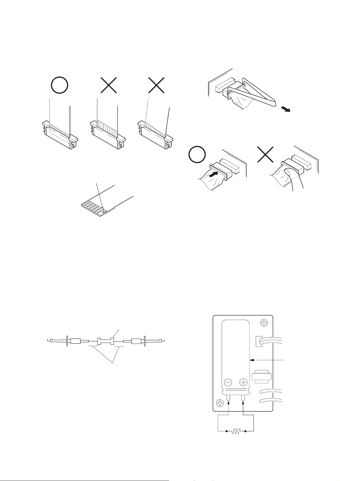
Make sure that the flat cable and flexible board are not cracked of
bent at the terminal.
Do not insert the cable insufficiently nor crookedly.
Cut and remove the part of gilt
which comes off at the point.
(Take care that there are
some pieces of gilt left inside)
When remove a connector, don't pull at wire of connector.
Be in danger of the snapping of a wire.
When installing a connector, don't press down at wire of connector.
Be in danger of the snapping of a wire.
[Discharging of the FLASH unit’s charging capacitor]
The charging capacitor of the FLASH unit is charged up to the
maximum 300 V potential.
There is a danger of electric shock by this high voltage when the
capacitor is handled by hand. The electric shock is caused by the
charged voltage which is kept without discharging when the main
power of the MVC-FD95 is simply turned off. Therefore, the
remaining voltage must be discharged as described below.
Preparing the Short Jig
To preparing the short jig. a small clip is attached to each end of a
resistor of 1 kΩ /1 W (1-215-869-11)
Wrap insulating tape fully around the leads of the resistor to prevent
electrical shock.
1 kΩ/1 W
Wrap insulating tape.
Discharging the Capacitor
Short circuits between the positive and the negative terminals of
charged capacitor with the short jig about 10 seconds.
Capacito
Short jig
— 3 —
Page 4
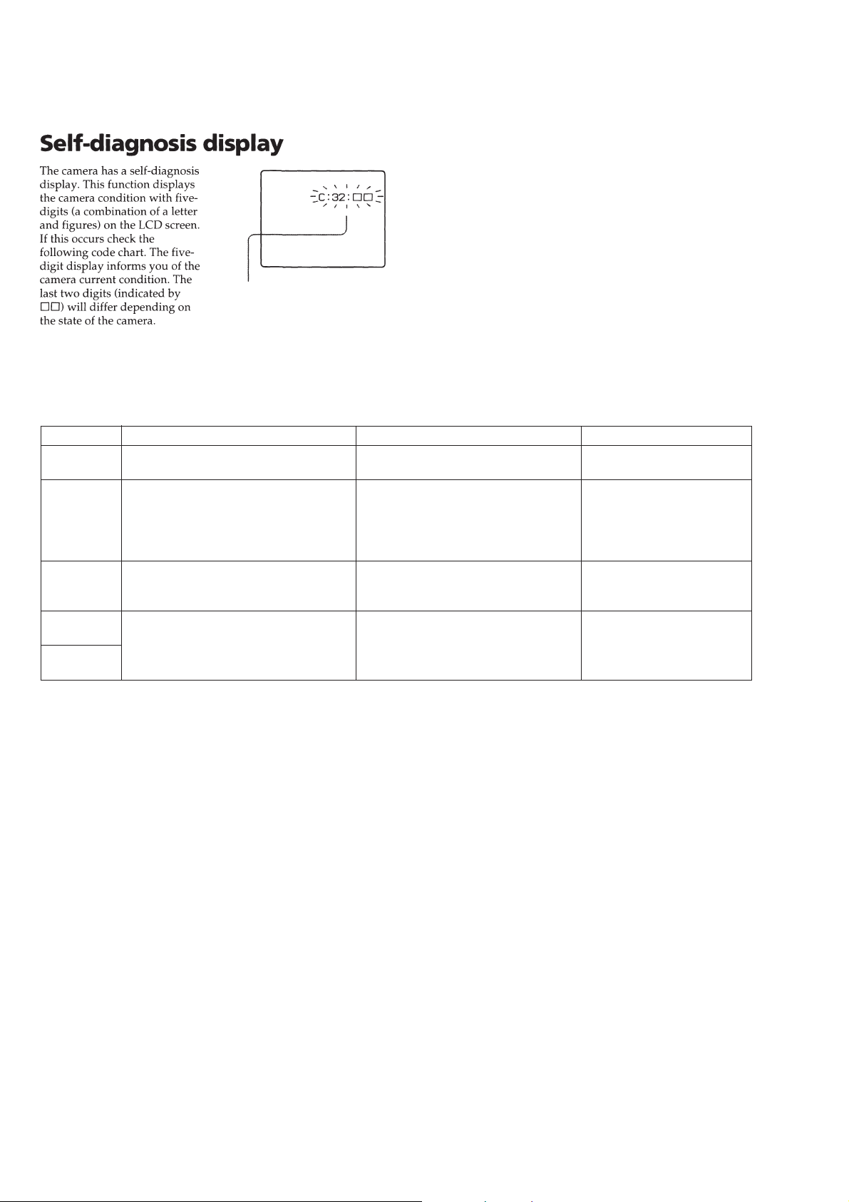
[Description on Self-diagnosis Display]
Self-diagnosis display
• C: ss: ss
The contents which can be handled
by customer, are displayed.
• E: ss: ss
The contents which can be handled
by engineer, are displayed.
Display Code
C:32:01
C:13:01
E:91:01
E:61:00
E:61:10
Countermeasure
Change the disk and turn off the main
power then back on.
Replace the floppy disk.
Format the floppy disk with the MVCFD95.
Checking of flash unit or replacement of
flash unit
Checking of lens drive circuit
Cause
Defective floppy disk.
• The type of floppy disk that cannot be
used by this machine, is inserted.
(Such as 2DD)
• Data is damaged.
• Unformatted disk is inserted.
Abnormality when flash is being
charged.
When failed in the focus initialization.
Caution Display During Error
DRIVE ERROR
DISK ERROR
Flash LED
Flash display
Flashing at 3.2 Hz
—
— 4 —
Page 5
1. MAIN PARTS
)
Note:
• Follow the disassembly procedure in the numerical order given.
• Items marked “*” are not stocked since they are seldom required for routine service. Some delay should
be anticipated when ordering these items.
• The parts numbers of such as a cabinet are also appeared in this section.
Refer to the parts number mentioned below the name of parts to order.
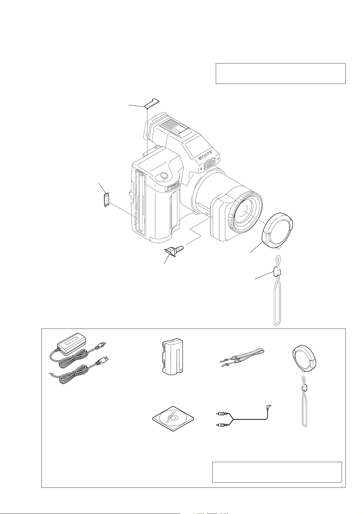
1. ORNAMENTAL PARTS
ACC jack cover
3-060-928-01
CPC Lid
3-058-792-11
Note : The components identified by mark 0 or dotted
line with mark 0 are critical for safety.
Replace only with part number specified.
MVC-FD95
Checking supplied accessories
AC-VF10 power adaptor (1)
0
1-475-599-11
Power cord set (1) (AEP model)
0
1-769-608-11
Power cord (with filter) (1) (UK model)
0
1-783-374-11
DC in cover
3-060-893-01
NP-F330 battery pack (1)
A-7094-141-A
Lens cap assembly
X-3950-691-1
Cap string
3-062-043-01
Shoulder belt (S) (1)
3-987-015-01
(Fig. A
(Fig. B)
Bundle soft (2000) (1)
Other accessories
3-061-389-11 MANUAL, INSTRUCTION (ENGLISH)
3-061-389-21 MANUAL, INSTRUCTION (FRENCH/GERMAN)(AEP MODEL)
3-061-389-31 MANUAL, INSTRUCTION (SPANISH/PORTUGUESE)(AEP MODEL)
3-061-389-41 MANUAL, INSTRUCTION (ITALIAN/DUTCH)(AEP MODEL)
3-061-389-61 MANUAL, INSTRUCTION (SWEDISH/RUSSIAN)(AEP MODEL)
3-060-716-01
— 5 —
Cord connector (A/V) (1)
1-783-738-11
Note : The components identified by mark 0 or dotted
line with mark 0 are critical for safety.
Replace only with part number specified.
(Fig. A) Lens cap assy (1)
X-3950-691-1
(Fig. B) Cap string (1)
3-062-043-01
Page 6
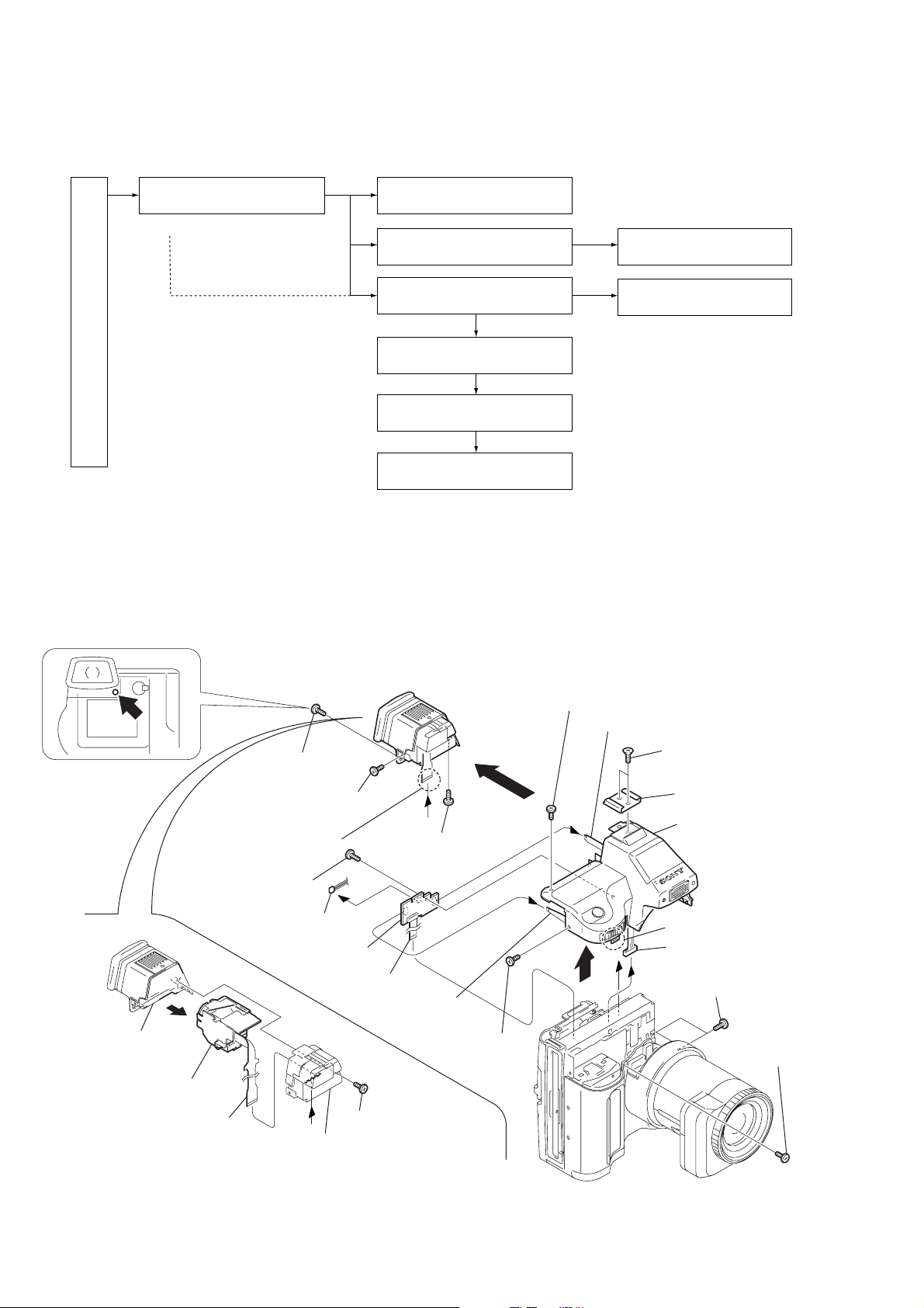
2. DISASSEMBLY
The following flow chart shows the disassembly procedure.
2-1. Cabinet (Top) assembly
MA-379 board
( 1- q;)
MVC-FD95
2-2. VF-143 board
VF lens assembly
2-8. AE-022 board
2-3. LCD, PK-49 board
2-4. FC-72, FU-139 boards,
Floppy disk drive
2-5. Lens compelete assembly
2-6. VP-50 board,
Lens block assembly
NOTE: F ollo w the disassembly procedure in the numerical order given.
2-1. CABINET (TOP) ASSEMBLY, MA-379 BOARD
2-9. Flash unit,
Microphone unit
2-7. Eject button section
5
Screw (M2 × 4),
lock ace, p2
qg
Screw (M2 × 4),
lock ace, p2
9
FP-173
flexible board (26P)
w;
Screw (M2 × 4),
lock ace, p2
ql
Microphone unit (2p)
wa
MA-379 board
q;
FP-171
flexible board (10P)
5
VF Cabinet
assembly
4
VF Lens assembly
2
FP-173
flexible board (26P)
3
Lid, VF
1
REMOVING THE VF CABINET ASSEMBLY
A
qf
Screw (M2 × 4),
lock ace, p2
qk
Control switch
block (6p)
4
Screw (M2 × 4),
lock ace, p2
Tapping screw (M2 × 5)
qh
3
Screw (M2 × 4), lock ace, p2
qj
FP-174 flexible cable
Two screws (M2 × 4),
qs
lock ace
qd
qa
6
Claw
8
7
A
Flash unit (10p)
1
Two screws (M2 × 4),
lock ace, p2
Accessory shoe
Top cabinet section
2
Screw (M2 × 4),
lock ace, p2
— 6 —
Page 7
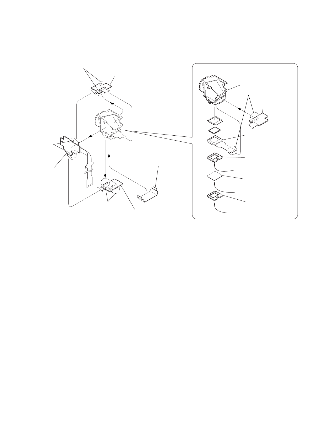
2-2. VF-143 BOARD, VF LENS ASSEMBLY
6
Two claws
7
VF-143 board (3)
4
Three
claws
5
VF-143
board (2)
3
Cover the cushion and diffusion plate
with a piece of paper or adhesive
tape or the like so that the parts must
not be scattered.
REMOVING THE VF LENS ASSEMBLY
VF lens assembly
1
LCD (LCX033AK-J)(16P)
(VF-143 board)
5
LCD (LCX033AK-J)
4
LCD cushion (1) (97)
Shining surface
3
BL illuminator (97)
Rough surface
1
Four claws
2
VF-143 board (1)
2
LCD cushion (2) (97)
Shining surface
— 7 —
Page 8
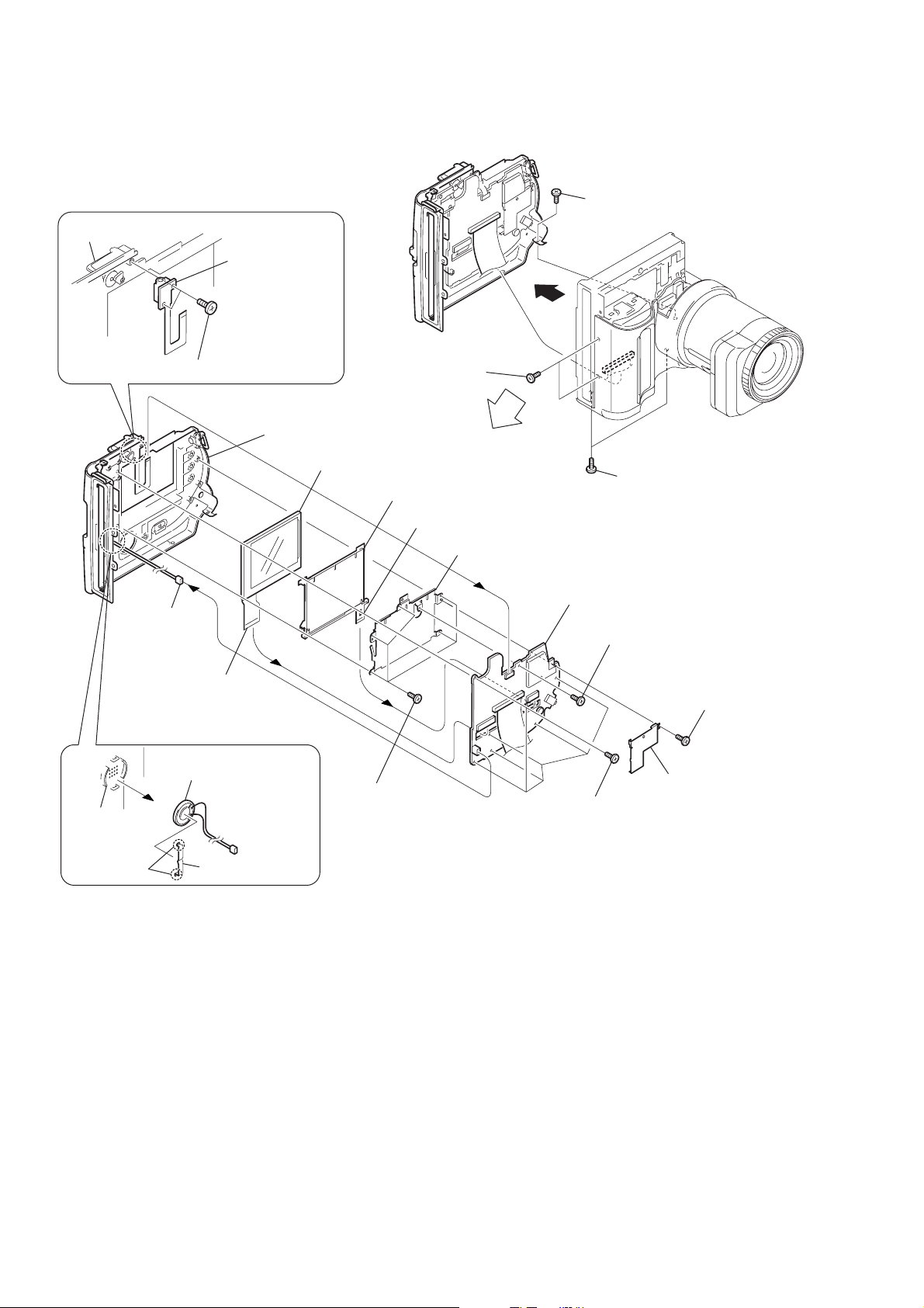
2-3. LCD, PK-49 BOARD
REMOVING THE FP-176 FLEXIBLE BOARD
Cabinet (rear)
2
FP-176 flexible
board (ACC jack)
1
Two tapping screws (M2 × 5)
Cabinet (rear) assembly
qh
Liquid cryst module indicator
7
Speaker
(2.0CM)(2p)
2
Two screws (M2 × 4),
lock ace p2
qg
Cold cathode fluorescent tube
6
Cold cathode fluorescent tube (10p)
qf
Back light retainer
4
1
Screw (M2 × 3), lock ace p2
3
Two screws (M2 × 4),
lock ace p2
qs
PK-49 board
q;
Screw (M2 × 3),
lock ace, p2
5
Liquid cryst module
indicator (24p)
REMOVING THE SPEAKER
3
Speaker (2.0CM)
Cabinet
(rear)
1
Two claws
2
Speaker retainer
qd
Five tapping
screws (M2
-49
K
P
oard
B
8
T apping
screw (M2
9
PK shield case
×
5)
(lower) assembly
×
5)
qa
Six tapping
screws (M2
×
5)
— 8 —
Page 9
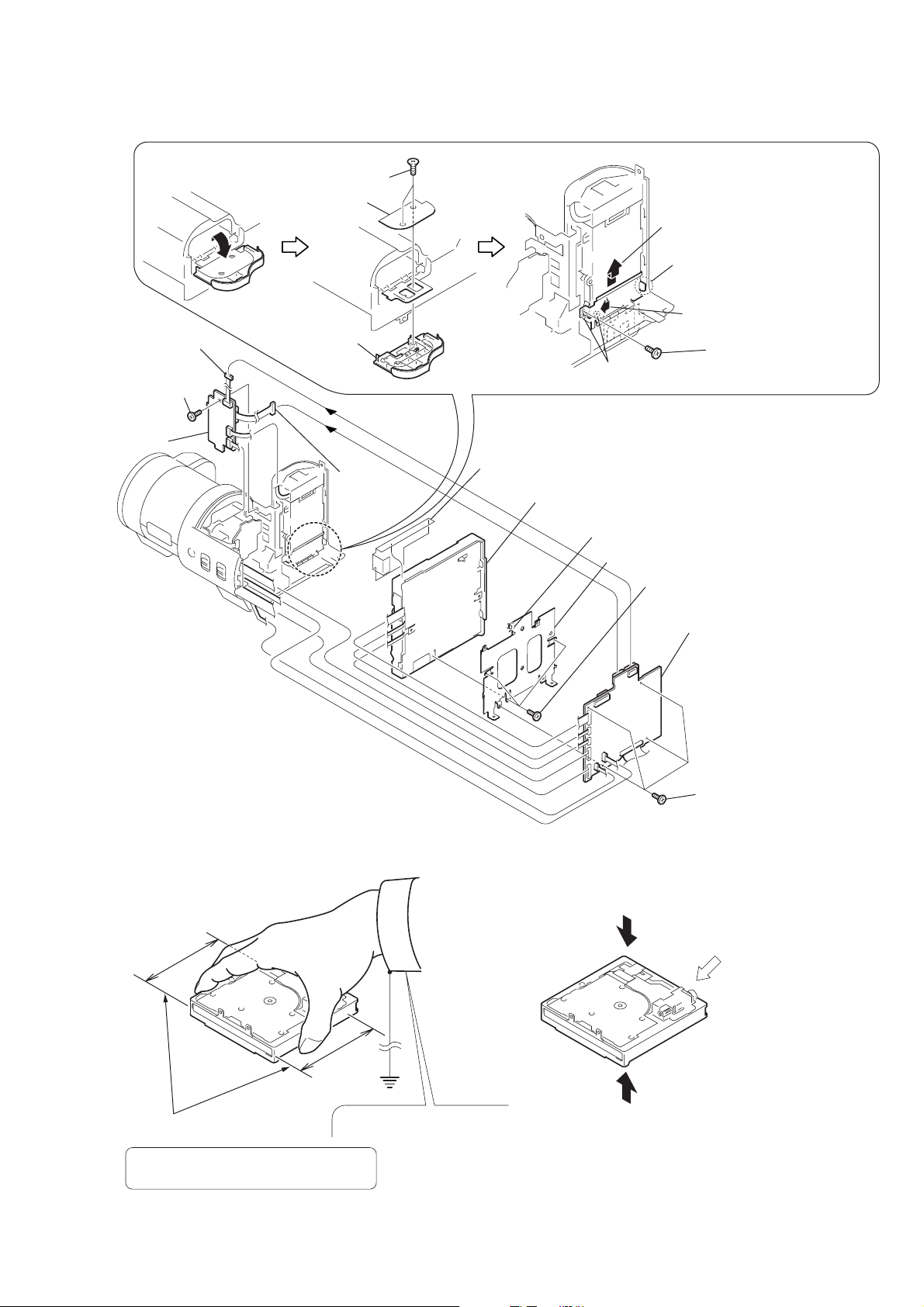
2-4. FC-72, FU-139 BOARDS, FLOPPY DISK DRIVE
2
T wo tapping
screws (M2 × 4)
3
Hinge retainer
1
3
Harness
(FU-54)(5p)
q;
Screw (M2 × 3),
lock ace, p2
qa
FU-139
board
4
Battery lid
4
Harness
(FU-53)(12p)
8
Sheet (B)
9
B
A
6
Two claws
REMOVING THE HINGE ASSEMBLY
Floppy disk drive
6
Claw
7
FC Bracket
9
Remove the hinge assembly
in the direction of the arrow B.
8
Claw
7
Remove the hinge assembly
in the direction of the arrow
5
5
Three screws
×
(M2
2.5)
T apping
screw (M2
×
5)
A
.
Cautions When Handling FDD
1. Correct Way of Holding an FDD
2
FC-72 board
FC-72
Board
1
Four screws
×
2.5)
(M2
2. Prohibited Items
Do not apply any physical stress to the center of the top plate.
Do not apply any physical
stress to the spindle motor.
Range of holding FDD
If the FDD is not held correctly,
the components of the FDD may be bent.
Wear an earthed wrist strap.
Do not hold an FDD by sandwiching
the upper and lower surfaces.
— 9 —
Page 10
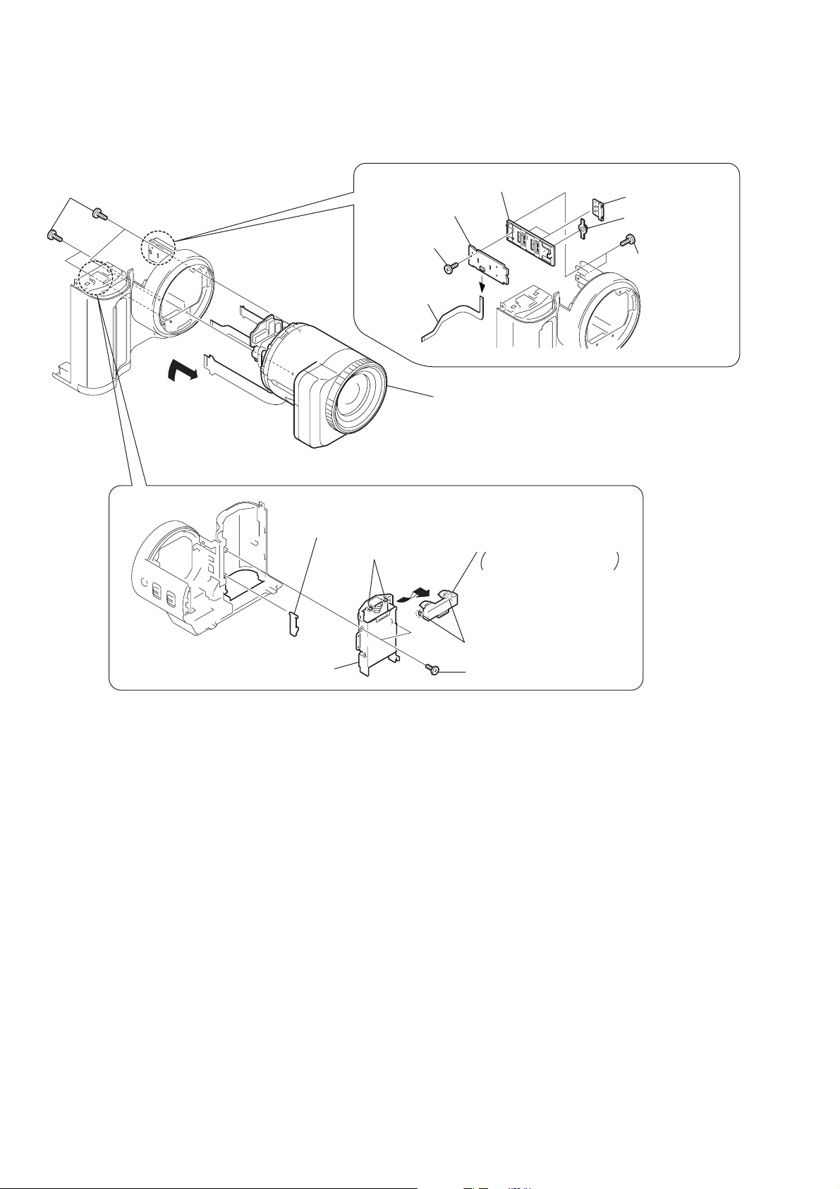
2-5. LENS COMPLETE ASSEMBLY
Four screws (M2 × 3), lock ace p2
1
REMOVING THE CF-074 BOARD
7
SS holder
3
CF-074 board
2
T apping
screw (M2
1
FP-172
flexible board (6p)
×
5)
5
Two SS knobs
6
Macro button
4
Two tapping screws
(M1.7
×
3.5)
A
2
REMOVING THE BA TTERY TERMINAL BOARD
3
BT lock claw
4
Two claws
B
2
Battery holder
Lens complete assembly
(Remove it in the direction of the arrow
6
Battery terminal board
Remove it in the
direction of the arrow
5
Two claws
1
Two tapping screws (M2 × 5)
B
.
A
.)
— 10 —
Page 11
2-6. VP-50 BOARD, LENS BLOCK ASSEMBLY
5
Two screws (M2 × 4),
lock ace p2
6
Screw (M2 × 4),
lock ace p2
C
8
7
Three claws
Cabinet (LT)
3
FP-177 flexible board (4p)
qf
FP-170 (7p)
qh
VP-50 board
qs
qg
FP-177 flexible board
qd
VP fixed plate
Two screws (M2 × 3),
lock ace p2
B
Be careflul not to damage
Note :
the FP-177 flexible board.
2
Two claws
(Note)
4
Cabinet
(VP) assembly
9
T wo tapping
screws (M2
REMOVING THE DC-IN CONNECTOR
3
T wo tapping
screws (M2
5
DC holder
6
DC-IN connector
B
Two screws (M2 × 3),
×
5)
qa
Cabinet (LB) assembly
(Remove it in the direction of the arrow
×
5)
q;
lock ace p2
1
Three tapping
screws (M2
2
Lens frame
4
Cabinet (LB)
1
Two screws (M2 × 4),
qj
Lens block assembly
lock ace p2
REMOVING THE CD-245 BOARD,
LENS ASSEMBLY, VAP ASSEMBLY
3
Two stapping crews (M1.7 × 6)
1
FP-166 flexible board (18p)
2
FP-170 flexible board (7p)
C
.)
9
CD-245
board
×
5)
qg
T ape (A)
8
CCD block assembly(CCD imager)
(Remove soldering)
qf
VAP assembly
(Remove it in the direction of the arrow
7
Seal rubber (CL)
6
Optical filter block
qd
qh
Lens assembly
qs
VAP assembly (5p)
(from VP-50 board)
Tapping screw (M1.7 × 6)
4
Four claws
5
CCD fitting
adaptor (CL)
D
q;
T ape (A)
D
.)
— 11 —
qa
FP-168 flexible board (13p)
Page 12

2-7. EJECT BUTTON SECTION
9
Claw
q;
Lock button
retainer
qd
Eject knob
qa
Lock button
qs
Lock button
spring
(PRECAUTION DURING INSTALLATION)
Knob
(Rack (B))
Attach the Rack(A) and
Gear Cover so that the
Rack(B) knob agrees with
the Gear Cover
while the Rack(A) is
pushed toward its top
most position.
A
position
A
(Gear cover)
Rack (A)
Gear cover
5
Pinion gear
6
Parallel pin (DIA. 1.6 × 8)
4
Rack (B)
3
2
Gear cover
1
Eject spring
Three tapping
screws (M2 × 5)
8
Rack (A)
7
Tapping screw (M1.7 × 4)
— 12 —
Page 13

2-8. AE-022 BOARD
w
8
3
Tape (A)
4
Screw (M2 × 4),
lock ace, p2
1
Tape (A)
FP-174 flexible board (5p)
6
Two screws (M2 × 4)
lock ace, p2
9
q;
AE sheet insulating
qa
5
Two claws
2
Harness (flash unit)(10p)
AE frame
7
AE button
AE-022 board
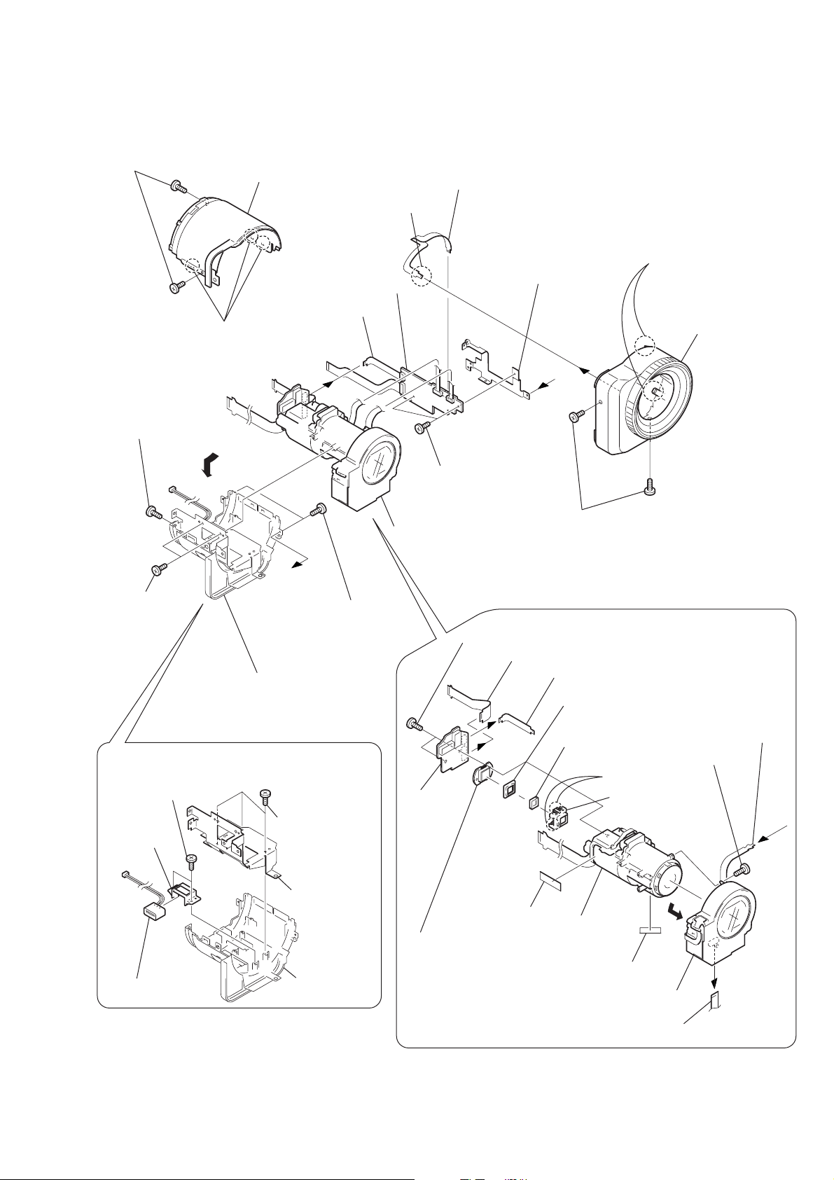
2-9. FLASH UNIT, MICROPHONE UNIT
qj
qk
Microphone
sheet
ql
T wo tapping
screws (M2
B
×
5)
Open button
Two
claws
3
T apping screw
×
(M1.7
REMOVING THE CONTROL
SWITCH BLOCK (zoom and shutter)
3
SW holder
(360)
4
Control
1
3.5)
Tape (A)
A
4
Remove the ST cabinet
(upper) in the direction
of the arrow
switch block
2
Two tapping
screws (M2 × 5)
A
.
qa
T apping screw
(M2
×
5)
qg
Tilt base
qf
T apping screw
×
5)
(M2
qs
Screw (M2 × 4),
lock ace, p2
C
INSTALLING THE FLASH UNIT
2
Attach the harness
of the flash unit
as shown.
qh
Flash unit
qd
ST assembly
B
q;
Blind assembly
9
T wo tapping
screws (M2
8
Flash unit (Note)
7
T wo tapping
screws (M2
5
7
Open
button
×
5)
×
5)
Sheet, waterproof
q;
Push down the flash unit.
C
6
Microphone unit (2p)
wa
Note : Do not touch the capacitor terminals,
an electric shock could result.
qh
T apping screw
(M1.7
2
T apping screw
(M1.7
1
Push the button to
raise the flash unit.
w;
Microphone
grille assembly
Microphone unit
qf
×
3.5)
qg
×
3.5)
ST cabinet
(upper)
T apping scre
(M1.7 × 3.5)
1
Flash unit
3
4
Tilt base
Tapping screw (M2 × 5)
6
5
Screw (M2 × 4),
lock ace, p2
T apping
screw (M2
Flash stand-by
switch
×
5)
— 13 —
8
Blind
assembly
9
T wo tapping
screws (M2
qa
Flash unit
qs
T wo tapping
screws (M2
×
5)
qd
Push the button to
×
5)
raise the flash unit.
Page 14

MVC-FD95
2-1. EXPLODED VIEWS
NOTE:
• -XX, -X mean standardized parts, so they may
have some differences from the original one.
• Items marked “*” are not stocked since they
are seldom required for routine service. Some
delay should be anticipated when ordering these
items.
2-1-1. OVERALL ASSEMBLY SECTION
2. REPAIR PARTS LIST
• The mechanical parts with no reference number
in the exploded views are not supplied.
The components identified by mark 0 or
dotted line with mark 0 are critical for safety.
Replace only with part number specified.
5
10
9
5
11
C
A
B
5
5
5
D
E
FC-72
5
6
Board
6
1
2
3
G
F
C
D
E
F
G
A
B
4
5
7
8
5
not
supplied
Ref. No. Part No. Description Remarks Ref. No. Part No. Description Remarks
1 1-678-338-11 FP-175 FLEXIBLE BOARD
2 not supplied FC-72(95) BOARD, COMPLETE (SERVICE)
* 3 3-062-814-01 FRAME, FDD
4 not supplied DRIVE, FLOPPY DISK
5 3-968-729-91 SCREW(M2), LOCK ACE, P2
6 7-627-854-07 PRECISION SCREW +P 2X2.5 TYPE3
7 X-3950-691-1 CAP ASSY, LENS
8 3-062-043-01 STRING CAP
9 3-724-511-51 SHOE, ACCESSORY
10 3-056-624-01 LOCK ACE, +K SCREW (M2)
11 3-968-729-51 SCREW (M2), LOCK ACE, P2
5
— 14 —
Page 15

2-1-2. TOP CABINET ASSEMBLY SECTION
F
F
A
A
G
G
H
H
C
E
E
I
I
C
B
B
D
D
51
51
51
55
52
52
53
55
56
58
57
59
61
64
69
54
62
63
65
71
67
66
60
51
51
51
71
72
55
51
70
68
55
not
supplied
not
supplied
not
supplied
not
supplied
not
supplied
not
supplied
not
supplied
MIC901
68
Included in 71
Ref. No. Part No. Description Remarks Ref. No. Part No. Description Remarks
51 3-948-339-61 TAPPING
52 not supplied SWITCH BLOCK, CONTROL (ZOOM BLOCK 360)
53 3-060-905-01 HOLDER (360), SW
54 not supplied MA-379 BOARD, COMPLETE
55 3-968-729-91 SCREW (M2), LOCK ACE, P2
56 1-678-328-11 FP-174 FLEXIBLE BOARD
57 1-678-325-11 FP-171 FLEXIBLE BOARD
58 not supplied AE-022 BOARD, COMPLETE
59 3-060-898-01 BUTTON, AE
60 3-695-567-01 WASHER (1.4), SPECIAL
61 X-3950-612-1 CABINET ASSY, TOP
62 3-060-913-01 STOPPER, SHOE
(ZOOM AND SHUTTER)
— 15 —
63 3-060-868-01 BUTTON, OPEN
64 3-062-299-01 SHEET, MICROPHONE
65 3-060-902-01 CABINET (UPPER), ST
66 X-3950-615-1 BLIND ASSY
67 3-060-871-01 BASE, TILT
68 3-713-791-51 SCREW (M1.7X3.5), TAPPING, P2
69 X-3950-614-1 GRILLE ASSY, MICROPHONE
70 X-3950-613-1 ST ASSY
0 71 not supplied FLASH UNIT
* 72 3-062-816-01 SHEET, WATERPROOF
MIC901 1-542-428-11 MICROPHONE UNIT
Note : The components identified by mark 0 or dotted
line with mark 0 are critical for safety.
Replace only with part number specified.
Page 16

2-1-3. EVF BLOCK ASSEMBLY SECTION
d
108
109
not
supplied
I
110
107
106
106
102
101
not
supplied
LCD902
J
I
J
not supplied
105
not supplied
106
103
104
not supplie
Ref. No. Part No. Description Remarks Ref. No. Part No. Description Remarks
101 X-3950-617-1 LENS ASSY, VF
102 1-678-327-12 FP-173 FLEXIBLE BOARD
103 3-060-922-01 LID, VF
104 3-948-339-61 TAPPING
105 3-058-233-01 ILLUMINATOR (97), BL
106 not supplied VF-143 BOARD, COMPLETE
107 X-3950-616-1 CABINET ASSY, VF
108 3-060-836-01 KNOB, VISIBILITY ADJUSTMENT
109 3-950-044-01 RING, O
110 3-060-921-01 ARM, VISIBILITY ADJUSTMENT
LCD902 not supplied LCX033AK-J
— 16 —
Page 17

2-1-4. CABINET (FRONT) BLOCK ASSEMBLY SECTION
A
A
B
B
152
153
154
155
156
155
174
159
176
155
155
174
155
163
160
177
161
162
164
165
166
167
168
169
170
171
172
157
158
174
174
173
175
151
not
supplied
BT901
not
supplied
not
supplied
Ref. No. Part No. Description Remarks Ref. No. Part No. Description Remarks
* 156 3-058-753-01 RETAINER, HINGE
151 3-060-842-01 LID, BATTERY
152 3-058-748-01 KNOB, B LOCK
153 3-058-749-01 LEVER, B LOCK
154 3-058-802-01 SPRING, B LOCK
155 3-948-339-61 TAPPING
157 3-719-381-01 SCREW (M2X4)
158 X-3950-609-1 CABINET (FRONT) ASSY
159 1-960-552-11 HARNESS (FU-53)
160 3-969-380-01 SPRING, BATTERY
165 3-050-468-01 SCREW, TRIPOD
166 3-713-790-31 SCREW (M2X8), TAPPING, P3
167 1-678-326-11 FP-172 FLEXIBLE BOARD
168 not supplied CF-074 BOARD, COMPLETE
169 3-060-895-01 HOLDER, SS
170 3-060-897-01 BUTTON, MACRO
171 3-060-896-01 KNOB, SS
172 3-060-843-01 PLATE, L FIXED
173 X-3950-24601 HOLDER ASSY, HINGE
174 3-968-729-51 SCREW (M2), LOCK ACE, P2
161 3-052-574-01 CLAW, BT LOCK
162 3-058-746-01 HOLDER, BATTERY
163 3-966-178-01 SCREW (1.7)
164 not supplied FU-139 BOARD, COMPLETE
175 3-736-363-41 TAPPING
176 1-960-553-11 HARNESS (FU-54)
* 177 3-058-801-01 SHEET, ST INSULATING
BT901 1-694-297-21 TERMINAL BOARD, BATTERY
— 17 —
Page 18

2-1-5. LENS COMPLETE ASSEMBLY SECTION
J901
226
209
225
210
208
226
207
226
IC101
204
212
225
211
not
supplied
206
213
205
214
215
216
not
supplied
220
Screw, tapping
217
219
218
A
224
221
223
227
201
not
supplied
202
A
225
not
supplied
205
203
not
222
supplied
226
not
supplied
226
Ref. No. Part No. Description Remarks Ref. No. Part No. Description Remarks
201 3-060-893-01 COVER, DC IN
202 X-3950-618-1 CABINET (LB) ASSY
203 3-965-098-01 SCREW
204 3-060-914-01 HOLDER, DC
205 3-968-729-51 SCREW (M2), LOCK ACE, P2
206 3-060-894-01 FRAME, LENS
207 3-060-890-01 CABINET (LT)
208 not supplied CD-245 BOARD, COMPLETE
209 3-947-268-11 TITE (2), +B TAPPING (P)
210 1-678-321-11 FP-166 FLEXIBLE BOARD
216 not supplied VAP ASSY
217 1-678-330-11 FP-177 FLEXIBLE BOARD
218 3-060-892-01 PLATE, VP FIXED
219 1-678-322-11 FP-168 FLEXIBLE BOARD
220 1-678-323-11 FP-169 FLEXIBLE BOARD
221 not supplied VP-50 BOARD, COMPLETE
222 3-965-060-01 PIN, MF FIXED
223 X-3950-611-1 CABINET (VP) ASSY
224 1-418-068-11 MF BLOCK
225 3-948-339-61 TAPPING
211 1-678-324-11 FP-170 FLEXIBLE BOARD
212 not supplied RUBBER (CL), SEAL
213 not supplied FILTER BLOCK, OPTICAL
214 not supplied ADAPTOR (CL), CCD FITTING
215 not supplied LENS ASSY
226 3-968-729-91 SCREW (M2), LOCK ACE, P2
227 3-060-854-01 BAND, RING
IC101 not supplied CCD BLOCK ASSY (CCD IMAGER)
J901 1-794-045-31 CONNECTOR, DC-IN
— 18 —
Page 19

2-1-6. CABINET (REAR) BLOCK ASSEMBLY SECTION
281
not
supplied
274
263
265
266
262
261
260
259
258
not
not
supplied
supplied
255
271
256
not
257
supplied
254
(Note)
253
279
278
Note : Refer to "Eject button section" on page 12
when installing the Rack (A).
252
267
251
270
251
268
251
269
SP901
264
LCD901
251
275
ND901
276
251
272
PK-49
Board
273
280
251
251
277
: BT701(Lithium battary) PK board on the mount position.
Ref. No. Part No. Description Remarks Ref. No. Part No. Description Remarks
251 3-948-339-61 TAPPING
252 3-058-787-01 RACK (A)
253 3-058-790-01 SPRING, EJECT
254 3-058-788-01 RACK (B)
255 3-060-839-01 RETAINER, P KNOB
256 3-058-786-01 GEAR, PINION
257 3-058-792-11 LID, CPC
258 3-058-782-01 KNOB, EJECT
259 3-058-783-01 BUTTON, LOCK
260 3-058-785-01 SPRING, LOCK BUTTON
261 3-058-784-01 RETAINER, LOCK BUTTON
262 3-060-838-01 KNOB, POWER
263 3-060-928-01 COVER, ACC JACK
264 1-678-329-21 FP-176 FLEXIBLE BOARD (INCLUDING JACK)
265 3-060-931-01 SHAFT, STRAP
266 3-060-850-01 RETAINER, MODE SELECTION
267 3-060-848-01 SHEET METAL (R), STRAP
268 3-060-927-01 COVER, AV JACK
269 3-060-932-01 DAMPER, FRICTION
270 3-060-886-01 SHEET METAL (L), STRAP
271 3-058-789-01 COVER, GEAR
272 3-060-889-01 PLATE, BL FIXED
273 not supplied PK-49 (CASI) BOARD, COMPLETE
273 not supplied PK-49 (SHAP) BOARD, COMPLETE
274 3-060-901-01 SHEET METAL, SELECTION CLICK
* 275 3-058-791-01 RETAINER, SPEAKER
276 3-061-157-11 BUTTON, FUNCTION
277 X-3950-622-1 CASE (LOWER) ASSY, Z SHIELD
278 X-3950-610-1 CABINET (REAR) ASSY
279 3-914-366-01 SCREW (DIA. 1.7X4), PRECISION
280 3-968-729-51 SCREW (M2), LOCK ACE, P2
281 X-3950-848-1 KNOB ASSY, MODE SELECTION (SERVICE)
LCD901 not supplied INDICATOR MODULE LIQUID CRYST (SH)
LCD901 not supplied INDICATOR MODULE LIQUID CRYST (CA)
0 ND901 not supplied TUBE, FLUORESCENT,COLD CATHODE
SP901 1-505-862-41 SPEAKER (2.0 CM)
— 19 —
Note : The components identified by mark 0 or dotted
line with mark 0 are critical for safety.
Replace only with part number specified.
Page 20

MVC-FD95
3. GENERAL
This section is extracted from
instruction manual.
— 20 —
Page 21

— 21 —
Page 22

— 22 —
Page 23

— 23 —
Page 24

— 24 —
Page 25

— 25 —
Page 26

— 26 —
Page 27

— 27 —
Page 28

— 28 —
Page 29

— 29 —
Page 30

— 30 —
Page 31

— 31 —
Page 32

— 32 —
Page 33

— 33 —
Page 34

MVC-FD95
9-929-828-41
Sony Corporation
Personal VIDEO Products Company
— 34 —
Printed in Japan © 2000.4
2000D1620-1
Published by Safety & Service Engineering Dept.
 Loading...