

Sony MVC-FD87, MVC-FD92 Service Manual
MVC-FD87/FD92
SERVICE MANUAL
Level 2
Ver. 1.0 2001. 02
PHoto: MVC-FD92
This service manual contains information for Japanese model as well.
When the machine needs to be repaired,
please refer to page 7 to discriminate the
type of LCD.
On the FC-85 board
This service manual procides the information that is premised the
circuit board replacement service and not intended repair inside the
FC-85 board.
Therefore, schematic diagram, printed wiring board and electrical
parts list of the FC-85 board is not shown.
The following pages are not shown.
US Model
Canadian Model
AEP Model
UK Model
E Model
Hong K ong Model
Australian Model
Korea Model
Japanese Model
FC-85 board
Schematic diagram.....................................Page 4-15 to 4-38
Printed wiring board ...................................Page 4-11 to 4-14
Electrical parts list ......................................Page 6-10 to 6-18
The above-described information is shown in service manual
Level 3.
System
Image device
5mFD92:
FD87:
Lens
FD92:
FD87:
Exposure control
Automatic exposure
White balance
Automatic, Indoor, Outdoor, Hold
m(1/3.6type)colorCCD
6.64 mm (1/2.7 type) color CCD
8× zoom lens
f = 4.75 – 38 mm (3/16 –
1 1/2 inches)
(41 – 328 mm
when
camera)
F = 2.8 – 3.0
3× zoom lens
f = 6.1 – 18.3 mm (1/4 –
(39 – 117 mm (1 9/16 –
when
camera)
F = 2.8 – 2.9
(1 5/8 – 13 inches)
converted into a 35 mm still
4 5/8 inches)
converted into a 35 mm still
3/4 inches)
SPECIFICATIONS
Data system
MoFD92: vie: MPEG
Still: JPEG, GIF (in TEXT
mode, Clip Motion), TIFF
Audio with still image:
MPEG (Monaural)
GIF (in TEXT mode)FD87:
Floppy disk: JPEG (JFIF)
“Memory Stick”: JPEG
(Exif2.1)
Recording medium
FlFD92: oppy disk:
3.5 inch 2HD MS-DOS
format (1.44 MB)
“Memory Stick”
FlFD87: oppy disk:
3.5 inch 2HD MS-DOS
format (1.44 MB)
“Memory Stick” (When using with
the MSAC-FD2M/FD2MA Floppy
Disk Adaptor for Memory Stick):
DCF format
Flash
Recommended recording
distance:
0.3mto2.5m(117/8inches
to 8 1/3 feet)
Input and Output
connector (FD92)
A/V OUT (MONO)
(Monaural)
Minijack Video:
1 Vp-p, 75 Ω, unbalanced,
sync negative
Audio: 327 mV (at a 47 kΩ
load)
Output impedance: 2.2 kΩ
ACC jack
Minijack
USB jack
mini-B
– Continued on next page –
DIGITAL STILL CAMERA

LCD screen
LCD panel
TFT (Thin Film Transistor
activematrix) drive
Total number of dots
123 200 (560×220) dots
General
Application
Sony battery pack NP-F330
(supplied)/F550
Power requirements
8.4 V
Power consumption
(During shooting)
3.5 W
Operating temperature
0°Cto40°C(32°Fto104°F)
Storage temperature
–20°Cto+60°C(–4°Fto
+140°F)
Dimensions (Approx.)
143×FD92:
103×79 mm
(5 3/4×41/8×3 1/8 inches)
(w/h/d)
143×FD87: 103×75 mm
(5 3/4×41/8×3 inches)
(w/h/d)
Mass (Approx.)
FD92:
660g(1lb7oz)(including
NP-F330 battery pack,
floppy disk and lens cap,
FD87: 630 g (1 lb 6 oz) (including
NP-F330 battery pack,
floppy disk and lens cap,
Built-in microphone (FD92)
Electret condenser
microphone
Built-in speaker (FD92)
Dynamic speaker
AC-L10A/L10B/L10C
AC power adaptor
Power requirements
100 to 240 V AC, 50/60 Hz
Rated output voltage
DC 8.4 V, 1.5 A in operating
mode
Operating temperature
0°Cto40°C(32°Fto104°F)
Storage temperature
–20°Cto+60°C(–4°Fto
Dimensions (Approx.)
125×39×62 mm (5×19/16×
(w/h/d)
Mass (Approx.)
280 g (10 oz)
+140°F)
2 1/2 inches)
etc.)
etc.)
NP-F330 battery pack
Battery type
Lithium ion
Maximum output
voltage
DC 8.4 V
Mean output voltage
DC 7.2 V
Capacity
5.0 Wh (700 mAh)
Operating temperature
0°Cto40°C(32°F to 104°F)
Dimensions (Approx.)
38.4 20.6 70.8 mm
(1 9/16 13/16 2 7/8 inches)
(w/h/d)
Mass (Approx.)
70 g (2 oz)
Accessories
AC-L10A/L10B/L10C
AC power adaptor (1)
Power cord (mains lead) (1)
USB cable (1) (FD92)
NP-F330 battery pack (1)
A/V connecting cable (1) (FD92)
Shoulder strap (1)
Lens cap (1)
Lens cap strap (1)
CD-ROM (SPVD-004 USB
Operating instructions (1)
Driver) (1)
SAFETY-RELATED COMPONENT WARNING!!
COMPONENTS IDENTIFIED BY MARK 0 OR DOTTED
LINE WITH MARK 0 ON THE SCHEMATIC DIAGRAMS
AND IN THE PARTS LIST ARE CRITICAL TO SAFE
OPERATION. REPLACE THESE COMPONENTS WITH
SONY PARTS WHOSE PART NUMBERS APPEAR AS
SHOWN IN THIS MANUAL OR IN SUPPLEMENTS PUBLISHED BY SONY.
SAFETY CHECK-OUT
After correcting the original service problem, perform the following
safety checks before releasing the set to the customer.
Design and specifications
without notice.
are subject to change
ATTENTION AU COMPOSANT AYANT RAPPORT
À LA SÉCURITÉ!
LES COMPOSANTS IDENTIFIÉS P AR UNE MARQUE 0
SUR LES DIAGRAMMES SCHÉMATIQUES ET LA LISTE
DES PIÈCES SONT CRITIQUES POUR LA SÉCURITÉ
DE FONCTIONNEMENT. NE REMPLACER CES COMPOSANTS QUE PAR DES PIÈCES SONY DONT LES
NUMÉROS SONT DONNÉS DANS CE MANUEL OU
DANS LES SUPPLÉMENTS PUBLIÉS PAR SONY.
1. Check the area of your repair for unsoldered or poorly-soldered connections. Check the entire board surface for solder
splashes and bridges.
2. Check the interboard wiring to ensure that no wires are
“pinched” or contact high-wattage resistors.
3. Look for unauthorized replacement parts, particularly transistors, that were installed during a previous repair. Point them
out to the customer and recommend their replacement.
4. Look for parts which, though functioning, show obvious signs
of deterioration. Point them out to the customer and recommend their replacement.
5. Check the B+ voltage to see it is at the values specified.
6. Flexible Circuit Board Repairing
• Keep the temperature of the soldering iron around 270 ˚C
during repairing.
• Do not touch the soldering iron on the same conductor of
the circuit board (within 3 times).
• Be careful not to apply force on the conductor when sol-
dering or unsoldering.
– 2 –

• Floppy disk that can be used by the MVC-FD87/FD92
• Size : 3.5-inch
• Type : 2 HD
• Capacity : 1.44 MB
• Format : MS-DOS format
(512 bytes × 18 sector)
(FD can be formatted by the MVC-FD87/FD92)
Table for differences of function
Model MVC-FD87 MVC-FD92
Image device 1/2.7-inch CCD 1/3.6-inch CCD
Lens 3 8
Digital zoom 6 16
Recording moving image – a
Audio with still image – a
MS socket – a
Digital I/O (USB) – a
CD board CD-318 CD-310
– 3 –

TABLE OF CONTENTS
Section Title Page Section Title Page
SERVICE NOTE ................................................................... 6
5. ADJUSTMENTS
Self-diagnosis Display ............................................................. 8
1. GENERAL
Introduction.............................................................................. 1-1
Identifying the Parts................................................................. 1-2
Preparing the Power Supply ................................................... 1-2
Setting the Date and Time ....................................................... 1-3
Inserting a Floppy Disk............................................................ 1-4
Inserting a “Memory Stick” ..................................................... 1-4
Recording Still Images ............................................................ 1-4
Recording Moving Images ...................................................... 1-6
Playing Back Still Images........................................................ 1-6
Playing Back Moving Images .................................................. 1-6
Viewing Images Using a Computer......................................... 1-7
Image File Storage Destinations and Image File Names....... 1-8
Before Performing Advanced Operations ............................... 1-9
Various Recording ................................................................... 1-11
Various Playback..................................................................... 1-15
Editing ..................................................................................... 1-16
As an External Drive................................................................ 1-18
Additional Information ............................................................. 1-18
Troubleshooting ....................................................................... 1-19
Warning and Notice Messages ............................................... 1-21
Self-diagnosis Display ............................................................. 1-21
LCD Screen Indicators ............................................................ 1-21
2. DISASSEMBLY
2-1. Cabinet (Rear) Block Assembly .................................... 2-1
2-2. FDD Block Assembly..................................................... 2-1
2-3. FC-85 Board.................................................................. 2-2
2-4. Lens Block Assembly .................................................... 2-2
2-5. PK-54 Board.................................................................. 2-3
2-6. LCD Module................................................................... 2-3
2-7. Circuit Boards Location................................................. 2-4
3. BLOCK DIAGRAMS
3-1. Overall Block Diagram .................................................. 3-1
3-9. Power Block Diagram 1................................................. 3-17
3-10. Power Block Diagram 2................................................. 3-19
4. PRINTED WIRING BOARDS AND
SCHEMATIC DIAGRAMS
4-1. Frame Schematic Diagrams ......................................... 4-3
Frame Schematic Diagram (1/2)................................... 4-3
Frame Schematic Diagram (2/2)................................... 4-5
4-2. Printed Wiring Boards and Schematic Diagrams ......... 4-7
CD-310 Printed Wiring Board and
Schematic Diagram ....................................................... 4-7
CD-318 Printed Wiring Board and
Schematic Diagram ....................................................... 4-9
FU-152 Printed Wiring Board....................................... 4-39
FU-152 Schematic Diagram......................................... 4-41
PK-54 Printed Wiring Board.......................................... 4-43
PK-54 (MODE SWITCH, A/V OUT)
Schematic Diagram ....................................................... 4-47
PK-54 (LCD DRIVE, TIMING GENERATOR)
Schematic Diagram ....................................................... 4-49
PK-54 (BACK LIGHT DRIVE) Schematic Diagram ...... 4-51
4-3. Waveforms .................................................................... 4-53
4-4. Parts Location ............................................................... 4-56
Before Starting Adjustment ..................................................... 5-1
1-1. Adjusting Items when Replacing
Main Parts and Boards.................................................. 5-2
5-1. Camera Section Adjustments........................................ 5-3
1-1. Preparations Before Adjustment ................................... 5-3
1-1-1. List of Service Tools ................................................. 5-3
1-1-2. Preparations............................................................. 5-4
1-1-3. Discharging of the Flashlight Power Supply............ 5-4
1-1-4. Precautions .............................................................. 5-6
1. Setting the Switch .................................................... 5-6
2. Order of Adjustments ............................................... 5-6
3. Subjects.................................................................... 5-6
4. Preparing the Flash Adjustment Box ....................... 5-7
1-2. Initialization of B, D, E, F, 7 Page Data ........................ 5-8
1-2-1. Initialization of D Page Data .................................... 5-8
1. Initializing D Page Data............................................ 5-8
2. Modification of D Page Data .................................... 5-8
3. D Page Table ............................................................ 5-9
1-2-2. Initialization of B, E, F, 7 Page Data ........................ 5-10
1. Initializing B, E, F, 7 Page Data ............................... 5-10
2. Modification of B, E, F, 7 Page Data........................ 5-10
3. B Page Table ............................................................ 5-10
4. E Page Table ............................................................ 5-10
5. F Page Table ............................................................ 5-11
6. 7 Page Table ............................................................ 5-13
1-3. Video System Adjustments ........................................... 5-14
1. Video Sync Level Adjustment (FD92)........................... 5-14
2. Video Burst Level Adjustment (FD92) .......................... 5-14
1-4. Camera System Adjustment ......................................... 5-15
1. Hall Adjustment ............................................................. 5-16
2. Flange Back Adjustment (Using the Minipattern Box).. 5-17
3. Flange Back Adjustment (Using the Flange Back
Adjustment Chart Subject More than 500 m Away) ..... 5-18
4. Flange Back Check ....................................................... 5-20
5. F No. Standard Data Input ............................................ 5-20
6. Mechanical Shutter Adjustment .................................... 5-21
7. Picture Frame Setting ................................................... 5-22
8. Light Level Adjustment and ND Shutter Check ............ 5-23
9. Mixed Color Cancel Adjustment.................................... 5-24
10. Auto White Balance Standard Data Input..................... 5-24
11. Auto White Balance ND Filter Compensation (FD92) .. 5-25
12. Auto White Balance Adjustment ................................... 5-26
13. Color Reproduction Adjustment .................................... 5-27
14. Color Reproduction Check ............................................ 5-28
15. Auto White Balance Check ........................................... 5-30
16. Strobe White Balance Adjustment ................................ 5-32
17. Strobe Light Level and White Balance Check .............. 5-33
18. CCD Black Defect Compensation................................. 5-34
19. CCD White Defect Compensation ................................ 5-35
1-5. LCD System Adjustments ............................................. 5-36
1. LCD Initial Data Input .................................................... 5-37
2. VCO Adjustment (FC-85 Board) ................................... 5-38
3. Black Limit Adjustment (FC-85 Board) ......................... 5-39
4. Bright Adjustment (FC-85 Board).................................. 5-39
5. Contrast Adjustment (FC-85 Board) ............................. 5-40
6. Color Adjustment (FC-85 Board) .................................. 5-40
7. VG Center Adjustment (FC-85 Board).......................... 5-41
8. V-COM Adjustment (FC-85 Board) ............................... 5-42
9. White Balance Adjustment (FC-85 Board) ................... 5-43
1-6. System Control System Adjustments ........................... 5-44
1. Battery Down Adjustment.............................................. 5-44
2. ZOOM Center Adjustment............................................. 5-45
3. Alignment Check (FDD Unit)......................................... 5-45
5-2. Service Mode ................................................................ 5-46
2-1. Adjusting Remote Commander..................................... 5-46
1. Used the Adjusting Remote Commander ..................... 5-46
2. Precautions upon Using the Adjusting
Remote Commander ..................................................... 5-46
2-2. Data Process................................................................. 5-47
2-3. Service Mode ................................................................ 5-48
1. Setting the Test Mode ................................................... 5-48
2. Bit Value Discrimination ................................................ 5-48
– 4 –

Section Title Page
3. Switch Check (1) ........................................................... 5-48
4. Switch Check (2) (FD92)............................................... 5-48
5. Switch Check (3) ........................................................... 5-49
6. LED Check .................................................................... 5-49
7. Self Diagnosis Code...................................................... 5-49
6. REPAIR PARTS LIST
6-1. Exploded Views............................................................. 6-1
6-1-1. Cabinet (Front) Section............................................ 6-1
6-1-2. Cabinet (Front) Assembly ........................................ 6-2
6-1-3. FDD Block Section ................................................... 6-3
6-1-4. Cabinet (Rear) Section ............................................ 6-4
6-1-5. Cabinet (Rear) Assembly ......................................... 6-5
6-1-6. Lens Block Section (FD87) ...................................... 6-6
6-1-7. Lens Block Section (FD92) ...................................... 6-7
6-2. Electrical Parts List........................................................ 6-8
* The color reproduction frame is shown on page 137.
– 5 –
SERVICE NOTE
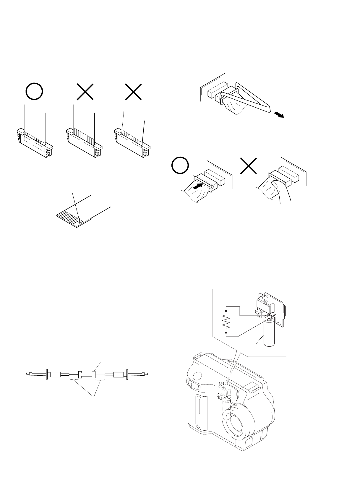
• NOTE FOR REPAIR
Make sure that the flat cable and flexible board are not cracked of
bent at the terminal.
Do not insert the cable insufficiently nor crookedly.
Cut and remove the part of gilt
which comes off at the point.
(Be careful or some pieces of
gilt may be left inside)
When remove a connector, don’t pull at wire of connector.
It is possible that a wire is snapped.
When installing a connector, don’t press down at wire of connector.
It is possible that a wire is snapped.
[Discharging of the FLASH unit’s charging capacitor]
The charging capacitor of the FLASH unit is charged up to the
maximum 300 V potential.
There is a danger of electric shock by this high voltage when the
battery is handled by hand. The electric shock is caused by the
charged voltage which is kept without discharging w hen the main
power of the MVC-FD87/FD92 is simply turned off. Therefore,
the remaining voltage must be discharged as described below.
Preparing the Short Jig
T o preparing the short jig. a small clip is attached to each end of a
resistor of 1 kΩ /1 W (1-215-869-11).
Wrap insulating tape fully around the leads of the resistor to prevent electrical shock.
1 kΩ/1 W
Wrap insulating tape.
Discharging the Capacitor
Short-circuit between the positive and the negative terminals of
charged capacitor with the short jig about 10 seconds.
R: 1 kΩ/1 W
(Part code:
1-215-869-11)
Capacitor
– 6 –
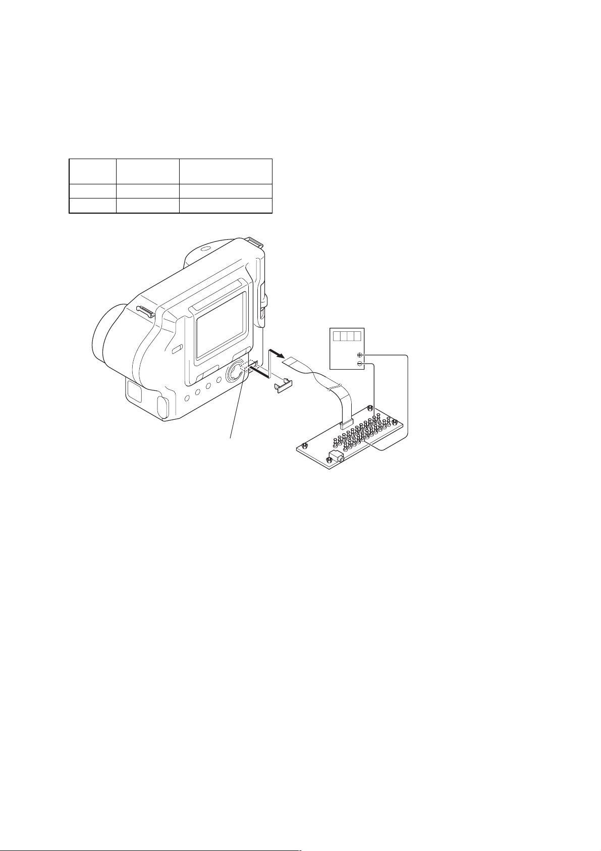
[LCD type check]
By measuring the resistor value between Pin qd of CN803 and Pin
4 of CN803 on FC-85 board, the type of LCD can be discrimi-
nated.
Note: About PK-54 board and LCD module, discriminate LCD
type on the machine, and replace the same type.
FC-85 board CN803
Resistor
value
LCD type PD board
10 kΩ TYPE SA PK-54 (TYPE SA)
22 kΩ TYPE ST PK-54 (TYPE ST)
Volt ohm meter
FC-85 board
CN803
22
1
CPC cover
qd pin
4 pin
1
22
CPC-12 jig
(J-6082-436-A)
– 7 –

[Description on Self-diagnosis Display]
Note : The “Self-diagnosis” data is backed up by the coin lithiumbattery.
The data will be lost and initialized when the coin lithium battery
is removed.
Display Code
C:32:01
C:13:01
E:91:01
Change the disk and turn off the main
power then back on.
Replace the floppy disk or “Memory
Stick” (FD92).
Format the floppy disk or “Memory
Stick” (FD92) with the MVC-FD87/
FD92.
Checking of flash unit or replacement of
flash unit
Countermeasure
Cause
Defective floppy disk.
• The type of floppy disk that cannot be
used by this machine, is inserted.
(Such as 2DD)
• Data is damaged.
• Unformatted disk or “Memory Stick”
(FD92) is inserted.
Abnormality when flash is being
charged.
E:61:00
E61:10
Checking of lens drive circuit
When failed in the focus initialization.
Note : The error code is cleared if the battery is removed, except defective flash, unit.
*1: When the flash charging failed, Page: D, Address: 67, Data: 04 are written.
After repair, be sure to write Page: D, Address: 67, Data: 00.
[Power supplying Method]
Use the AC power adaptor (AC-L10A) when supplying the power to this set.
Caution Display During Error
DRIVE ERROR
DISK ERROR
MEMORY STICK ERROR
(FD92)
Flash LED
*1
Flash display
Flashing at 3.2 Hz
—
– 8 –
SECTION 1
GENERAL
MVC-FD87/FD92
This section is extracted from
MVC-FD92 instruction manual.
.
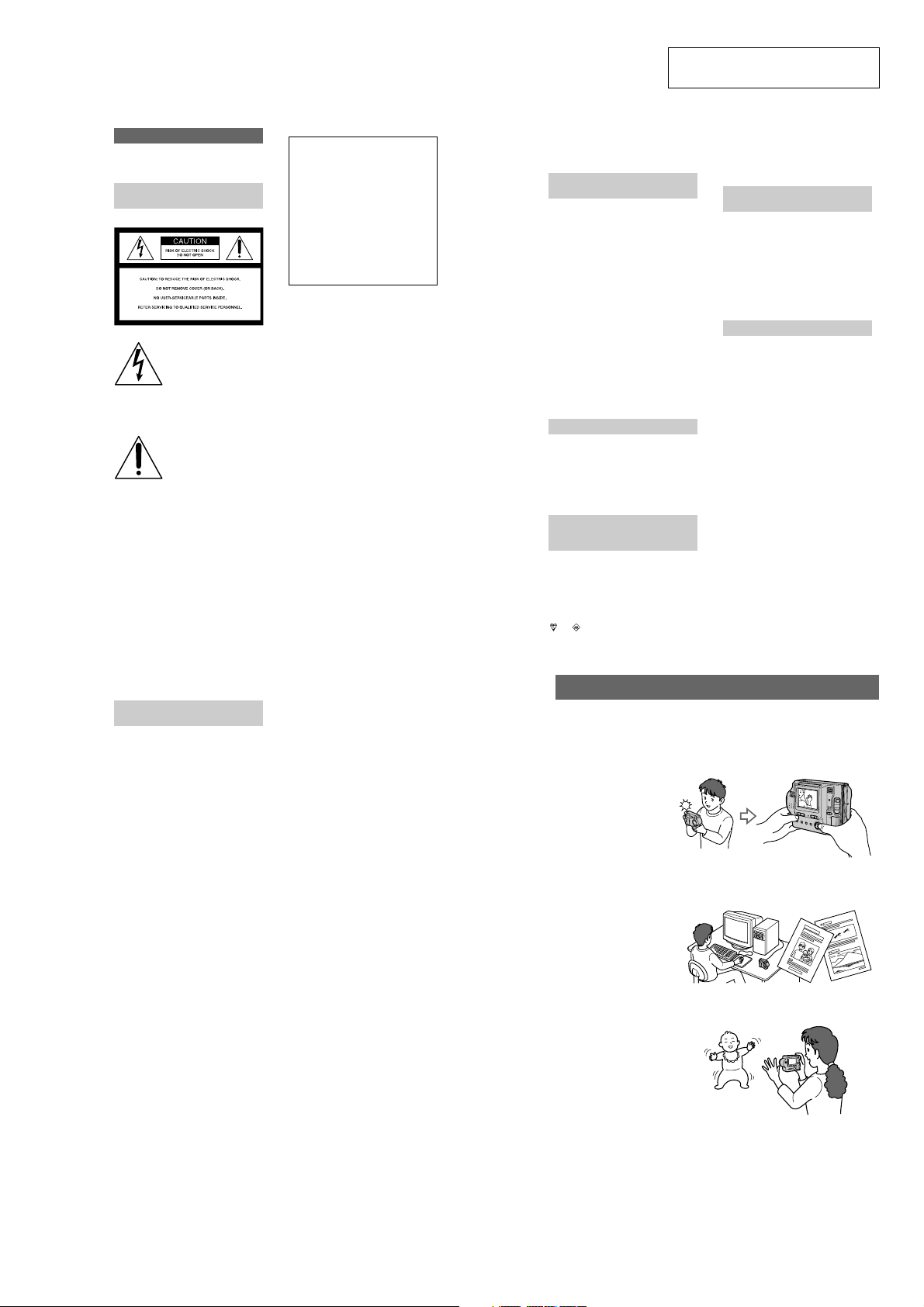
WARNING
To prevent fire or shock hazard, do
not expose the unit to rain or
moisture.
For the Customers in the
U.S.A.
This symbol is intended to
alert the user to the presence
of uninsulated “dangerous
voltage” within the
product’s enclosure that
may be of sufficien t
magnitude to constitute a
risk of electr ic shock to
persons.
This symbol is intended to
alert the user to the presence
of important operating and
maintenance (servicing)
instructions in the lite rature
accompanying the
appliance.
If you haveany questions about this product,
you may call:
Sony Customer Information Center
1-800-222-SONY (7669)
The number below is for the FCC related
matters only.
Regulatory Information
Declaration of Conformity
Trade Name: SONY
Model No.: MVC-FD92
Responsible Party: Sony Electronics Inc.
Address: 1 Sony Drive, Park
Telephone No.: 201-930-6972
This device complieswith Part 15of the FCC
Rules. Operation is subj ect to the following
two conditions: (1) Thi s device may not
cause harmful interference, and (2)this
device must acceptany interference received,
including interference that may cause
undesired operation.
CAUTION
You are cautioned that any changes or
modifications not expres sly approved
in this manual could void y our
authority to operate this equipment.
Note:
This equipment has been tested and found to
comply with the limi ts for a Class B digital
device, pursuant to Part 15 of the FCC
Rules. These limits are design ed to provide
reasonable protection against harmful
interference in a residential installation. This
equipment generates, uses, and can radiate
radio frequency energy and, if not installed
and used in accordance with the
instructions, maycause harmful interference
to radio communications. However, there is
no guarantee that interference will not occur
in a particular installation. I f this equipment
does cause harmful interference to r adio or
television reception,which can be
determined by turning thee quipmentoff and
on, the user is encouraged to try to c orrect
the interference by one or more of the
following measures:
— Reorient or relocate the receiving ante nna.
— Increase the separation between the
equipment and receiver.
— Connect the equipment into an outlet on
a circuit different from that to whic ht he
receiver is co nnected.
—C onsult the dealer or an experienced
radio/TV technician for hel p.
Ridge, NJ, 07656 USA
The supplied interface cable must be use d
with the equipment in order to comply with
the limits for a digita l device pursuant to
Subpart B of Part 15 of FCC Rules.
For the Customers in the
U.S.A. and Canada
DISPOSAL OF LITHIUM ION
BATTERY.
LITHIUM ION BATTERY.
DISPOSE OF PROPERLY.
You can return your unwanted lithium ion
batteries to your nearest Sony Service
Center or Factory S ervice Center.
Note:
In some areas the disposal of lithium ion
batteries in household or business trash may
be prohibited.
For the Sony ServiceCenter nearest you call
1-800-222-SONY (United States onl y)
For the SonyFactory Service Center nearest
you call 416-499-SONY (Canada only)
Caution:
Do not handle damaged or leaking lithium
ion battery.
For the Customers in Canada
CAUTION
TO PREVENTELECTRIC SHOCK, DO NOT
USE THIS POLARIZED AC PLUG WITH
AN EXTENSION CORD, RECEPTACLE OR
OTHER OUTLET UNLESS THEBLADES
CAN BE FUL LY IN SERTED TO PREVENT
BLADE EXPOSURE .
NOTICE FOR THE
CUSTOMERS IN THE UNITED
KINGDOM
A moulded plug complying with BS 1363 is
fitted to this equipment for your safety and
convenience.
Should the fuse in the plug suppli ed need to
be replaced, a 5 AMP fuse approved by
ASTA or BSI to BS 1362, (i.e. marked with
or mark) must be us ed.
If the plug supplied with this equ ipment has
a detachable fuse cover,be sure to attach the
fuse cover after you change the fuse. Never
use the plug without the fuse cover. If you
should lose the fuse cover, please contact
your nearest Sony service station.
For the Customers in
Germany
Directive:EMC Directive 89/336/EEC.92/
31/EEC
This equipment complies with th e EMC
regulations when used under the fol lowing
circumstances:
• Residential area
• Business district
• Light-industry district
(This equipment complies with the EMC
standard regulations EN55022 Cl ass B.)
Attention
The electromagnetic fields at the specific
frequencies may influence th e picture and
sound of this camera.
2
Be sure to read the following
before using your camera
Operating instructions
Before operating the u nit, please read this
manual thoroughly, and retain it for future
reference.
As you read through this manua l, buttons
and settings on the ca mera are shown in
capital letters.
e.g. Press DISPLAY.
Trial recording
Before you record one-time events, you may
want to make a trial recordi ng to make sure
that the camera is working correctly.
No compensation for contents of
the recording
Contents of the recording cannot be
compensated for if recording or playback is
not made due to a malfunctio no f your
camera or recording medium, etc .
Notes on im age data com patibility
of the “Memory Stick”
• Thiscamera conforms withthe Design rule
for Camera File system universal stan dard
established by the JEITA (Japan Electrics
and Information Technology Industries
Association). You cannot play back on
your camera still images recorded on other
equipment (DCR-TRV890E/TRV900/
TRV900E, DSC-D700, DSC-D770) that
does not conform with this universal
standard. (These models ar e not sold in
some areas.)
• Playback of images recorded with your
camera on other equipment and pla yback
of images recorded or edited w ith other
equipment on your camera are not
guaranteed.
Precaution on copyright
Television programs, films, video tapes, and
other materials may be copyrighted.
Unauthorized recording ofs uch materials
may be contrary to the provi sion of the
copyright laws.
4
Do not shake or strike the camera
In addition to malfunct ions and inability to
record images, this may ren der the floppy
disks or “Memory Stick”s unusable or
image data breakdown, damage or loss may
occur.
LCD screen, finder (only models
with a finder) and lens
• The LCD screenand the finder are
manufactured using extremely high precision technology so over 99.99% o f
the pixels are operational for effectiveuse.
However, there may be some tiny black
points and/or bright points (wh ite, red,
blue or green in color) that consta ntly
appear on the LCD screen and the finder.
These points are normal in the
manufacturing process and do not affect
the recording in any way.
• Be careful when placing the camera near a
window or outdoors. Exposing the LCD
screen, the finder or the lens to direc t
sunlight for long periods may cause
malfunctions.
Do not get the camera wet
When taking pictures outdoors in the rain or
under similar conditions, be car eful not to
get the camera wet. If moisture
condensation occurs, refer to page 72 a nd
follow the instructions on how to remove it
before using the camera.
Back up recommendation
To avoid the potential risk of data loss,
always copy (back up) data to a disk.
When the camera is used for long
periods
Note that the camera body may b ecome hot.
3
Introduction
Deletes undesired images right away, checking the image
after shooting
The digital still camera is able to play back the image and delete it right away.
Recording still images:
page 18
Playing back still images:
page 24
Deleting images
(DELETE): page 64
Captures images with your computer
Youcan easily copy images onto your computer using a floppy disk or a “Memory
Stick,” and view and modify images on your computer using application software.
Viewingimages using a
computer: page 27
Records a moving picture with audio
The digital still camera can record a moving picture with audio for maximum 60 seconds.
Recording moving
images: page 23
Selects the recording mode from various types of recordings
according to your situation
Creating Clip Motion Files: page 47
Recording still images for e-mail (E-MAIL): page 49
Adding audio files to still images (VOICE): page 50
Recording text documents (TEXT): page 51
Recording still images as uncompressed files (TIFF): page 52
6
1-1
Getting started
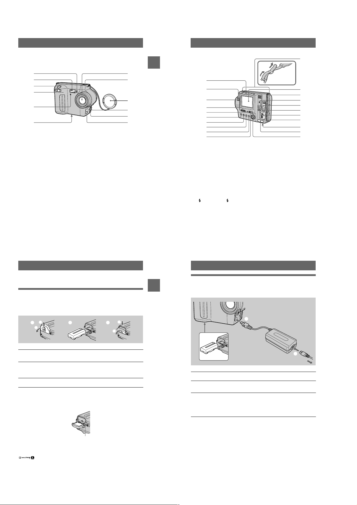
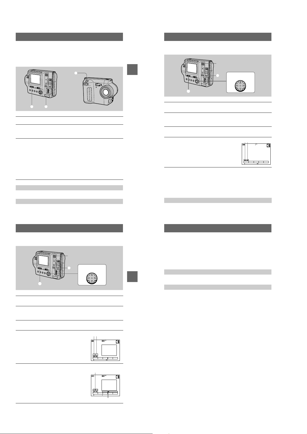
Identifying the parts
See the pages in parentheses for details of operation.
1
2
3
4
5
6
Self-timer lamp (22)
A
Flash (22)
B
Shutter button (18, 23)
C
Zoom lever (20)
D
Photocell window for flash
E
Do not block while recording.
Tripod receptacle (bottom
F
surface)
Useatripodwithascrewlengthof
less than 6.5 mm (7/32 inch). You
cannot firmly secure the camera to
tripods having longer screws, and
may damage the camera.
G
H
I
J
K
L
7
8
9
0
qa
qs
Lens
Built-in microphone
Do not touch while recording.
Lens cap (supplied)
ACC (Accessory) jack
A/V OUT (MONO) jack (62)
Audio output is monaural.
DC IN cover/DC IN jack (10, 13)
qa
Getting started
1
2
Attaching the
shoulder strap
qs
qd
3
4
5
6
7
8
9
0
Photocell window for LCD
A
screen
The LCD screen becomes brighter
when exposed to sunlight.
VOLU ME + /– buttons (26)
B
LCD BACKLIGHT switch (20)
C
PLAY/STILL/MOVIE selector
D
(38)
POWER ON/OFF (CHG)
E
(Charge) lamp (10)
(Flash) button/ ( Flash)
F
lamp (22)
FOCUS button (5 3)
G
PROGRAM AE button (54)
H
DISPLAY button (21)
I
POWER switch (14)
J
Hooks for strap
K
LCD screen
L
Floppy disk slot (16)
M
Access lamp (18, 19)
N
DISK EJECT lever (16)
O
Speaker
P
“Memory Stick” cover/
Q
“Memory Stick” slot (17)
MS /FD (“Memory Stick”/floppy
R
disk) selector
Battery cover (9)
S
USB cover/USB jack (29)
T
Control button (38)
U
qf
qg
qh
qj
qk
ql
w;
wa
Preparing the power supply
Installing the battery pack
Yourcamera operates only with the NP-F330 (supplied)/F550 (not supplied)
“InfoLITHIUM” battery pack* (L series). See page 75 for more information about
“InfoLITHIUM” battery pack.
1
1 2 3
2
Open the battery cover.
1
Slide the battery cover in the direction of the arrow.
Install the battery pack.
2
Insert the battery pack with the
as illustrated.
Close the battery cover.
3
mark facing toward the battery compartment
v
To remove the battery pack
Open the battery cover. Slide the battery eject lever rightward, and remove
the battery pack.
Be careful not to drop the battery pack when removing it.
Battery eject lever
*
What is “InfoLITHIUM”?
“InfoLITHIUM” is a lithium ion battery pack which can exchange information such as battery
consumption with compatible video equipment. “InfoLITHIUM” L series battery packs have the
mark. “InfoLITHIUM” is a trademark of Sony Corporation.
2
1
7
8
Charging the battery pack
When the camera is turned on, you cannot charge the battery pack. Be sure to turn off
Getting started
the power of the camera.
2
to DC IN jack
1
Battery pack
Insert the battery pack into your camera.
1
Open the DC IN cover and connect the AC power adaptor to the DC
2
IN jack of your camera with the
Connect the power cord (mains lead) to the AC power adaptor and
3
then to a wall outlet (mains).
The POWER ON/OFF (CHG) lamp (orange) below the LCD screen lights up
when charging begins. When the POWER ON/OFF (CHG) lamp goes off, full
charge is completed.
mark facing up.
v
AC-L10A/L10B/L10C
AC power adaptor
Power cord
(mains lead)
3
to a wall outlet ( mains)
After charging the battery pack
Disconnect the AC power adaptor from the DC IN jack on your camera.
Battery remaining indicator
The LCD screen on the camera shows the remaining time for which you can still
record or play back images.
This indication may not be entirely accuratedepending on the conditionsof use and
the operating environment.
Charging at a room temperature of 10°Cto30°C(50°Fto86°F) is recommended.
9
10
1-2
NP-F330 (supplied)/F550 (not supplied) battery pack
When you record images in an extremely cold location or using the LCD screen, the
operatingtime becomes short. When using the camera in an extremely cold location,
place the battery pack in your pocket or other place to keep it warm, then insert the
battery pack into the camera just before recording. When using a pocket heater, take
care not to let the heater directly contact the battery.
Auto power-off function
If you do not operate the camera for about three minutes during recording, the camera
turns off automatically to prevent wearing down the battery pack. To use the camera
again, slide the POWER switch to the right to turn on the camera again.
Note on the POWER ON/OFF (CHG) lamp during charging
The POWER ON/OFF (CHG) lamp may flash:
• When a malfunction occurs in the battery pack.
The POWER ON/OFF (CHG) lamp does not light up:
• When the battery pack is not installed properly.
Charging time
Battery pack Full charge (min.)
NP-F330 (supplied) Approx. 150
NP-F550 Approx. 210
Approximate time to charge a completely discharged battery pack at a temperature of
25°C(77°F).
Battery life and number of images that can be recorded/played back
STILL mode recording/playback when using floppy disks
NP-F330 (supplied) NP-F550
Continuous
recording*
Continuous
playback**
Battery life
(min.)
Approx. 70 Approx. 750 Approx. 150 Approx. 1600
Approx. 80 Approx. 2200 Approx. 170 Approx. 4800
Number of
images
Battery life
(min.)
Number of
images
STILL mode recording/playback when using “Memory Stick”s
NP-F330 (supplied) NP-F550
Battery life
Getting started
Continuous
recording*
Continuous
playback**
Approximate battery life and number of images that can be recorded/played back at a
temperature of 25°C(77°F) w ith a fully charged battery pack, 640×480 image size
and in NORMAL recording mode.
∗ Recording at about 5-second intervals when using a floppy disk, or at abo ut3- second intervals
when using a “Memory Stick”
∗∗Pla ying back single images continuously at about 2-second int ervals
(min.)
Approx. 80 Approx. 1600 Appr ox. 170 Approx. 3400
Approx. 100 Approx. 3000 A pprox. 230 Ap prox. 6900
Number of
images
Battery life
(min.)
Number of
images
MOVIE mode recording when using floppy disks
NP-F330 (supplied) NP-F550
Battery life (min.) Battery life (min.)
Continuous recording Approx. 85 Approx. 180
MOVIE mode recording when using “Memory Stick”s
NP-F330 (supplied) NP-F550
Battery life (min.) Battery life (min.)
Continuous recording Approx. 90 Approx. 190
Approximate time that can be recorded at a temperature of 25°C(77°F) and 160×112
image size with a fully charged battery pack.
Notes
• The battery life and number of images will be decreased when using at low temperature, using
the flash, turning the power on/off frequen tly, or using the zoom.
• The capacity of the floppy disk or “Memory Stick” is limited. The above figures are as a guide
when you continuously record/play ba ck by replacing the floppy disk or “Memory Stick.”
• If sufficient battery remaining time is indicated but th e power runs out soon, fully charge the
battery so that the correct ba ttery remaining time appears.
• Do not short the DC plug of the AC power adaptor with a metallic object, a s this may cause a
malfunction.
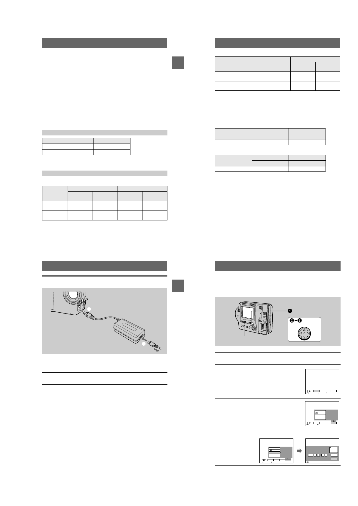
Using the AC power adaptor
1
to DC IN jack
Open the DC IN cover and connect the AC power adaptor to the DC
1
IN jack of your camera with the
Connect the power cord (mains lead) to the AC power adaptor and
2
then to a wall outlet (mains).
Using a car battery
Use Sony DC adaptor/charger.
Using your camera abroad
For details, see page 74.
When using the AC power adaptor
Be sure to use it near a wall outlet. If a malfunction occurs, disconnect the plug from
the wall outlet.
v
AC-L10A/L10B/L10C
AC power adaptor
to a wall outlet (mains)
mark facing up.
Power cord
(mains lead)
2
11
12
Setting the date and time
When you first use your camera, set the date and time. If these are not set, the
Getting started
CLOCK SET screen appears whenever you turn on your camera.
Control button
POWER ON/OFF
(CHG) lamp
Slide the POWER switch to the right to turn on the power.
1
The POWER ON/OFF (CHG) (green) lamp lights up.
Pressvon the control button.
2
The menu bar appears on the LCD screen.
EFFECT FILE SETUP
SELECT OK
Select [SETUP] withBon the control button,
3
then press the center
Select [CLOCK SET] withv/Von the control button, then press the
4
center
.
z
.
z
VIDEO OUT
CLOCK SET
BEEP
LCD BRIGHT
EFFECT FILE SETUP
SELECT CLOSE
/LANGUAGE
CAMERA
MENU BAR OFF
CAMERA
13
1-3
14
VIDEO OUT
/LANGUAGE
CLOCK SET
BEEP
LCD BRIGHT
EFFECT FILE SETUP
SELECT OK
CAMERA
200111
12:00:00A
CLOCK SET
M
2001 :/ / 1 1 12 00 AM
SELECT
Y/M/D
M/D/Y
D/M/Y
ENTER
CANCEL
OK
Select the desired date display format with
5
on the control button,then press the
v/V
center
.
z
Select from [Y/M/D] (year/month/day), [M/D/Y]
(month/day/year), or [D/M/Y] (day/month/year).
Select the year, month, day, hour or minute
6
itemyouwanttosetwith
button.
The item to be set is indicated with
Set the numeric value withv/Von the
7
control button, then press the center
enter it.
After entering the number,
item. If you selected [D/M/Y] in step
time on a 24-hour cycle.
Select [ENTER] withBon the control button,
8
then press the center
moment to begin clock movement.
The date and time are entered.
on the control
b/B
v/V
moves to the next
v/V
at the desired
z
5
.
,setthe
CLOCK SET
2001 : 1 1 12 00 AM//
OK
SELECT/ADJUST
CLOCK SET
2001 :/ / 1 1 12 00 AM
OK
SELECT/ADJUST
to
z
CLOCK SET
2001/ :/ 1 7 12 00 AM
OK
SELECT/ADJUST
CLOCK SET
2001/ :/ 4 7 10 30 PM
OK
SELECT
To cancel the date and time setting
Select [CANCEL] withv/V/b/Bon the control button, then press the centerz.
Y/M/D
M/D/Y
D/M/Y
ENTER
CANCEL
Y/M/D
M/D/Y
D/M/Y
ENTER
CANCEL
Y/M/D
M/D/Y
D/M/Y
ENTER
CANCEL
Y/M/D
M/D/Y
D/M/Y
ENTER
CANCEL
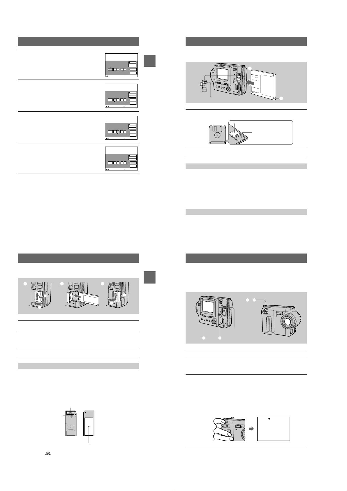
Inserting a floppy disk
Getting started
EJECT lock
Check that the write protect tab is set to the recordable position for
1
recording.
Insert the floppy disk until it clicks.
2
DISK EJECT lever
Usable floppy disks
• Size: 3.5 inch
• Type: 2HD (1.44 MB)
• Format: MS-DOS format (512 bytes × 18 sectors)
Notes
• Do not insert the media other than the floppy disks described above.
• You cannot use the optional MSAC-FD2M/FD2MA Floppy Disk Adaptor for Memory Stick.
• Never remove the floppy disk, turn off the power, or change the position of the MS/FD selector
while the access lamp is lit up.
Removing the floppy disk
While sliding the EJECT lock to the left, slide down the DISK EJECT lever.
2
1
Recordable/erasable
Unrecordable/unerasable
Inserting a “Memory Stick”
1 2 3
1
2
Open the “Memory Stick” cover.
1
Slide the cover in the direction of the arrow.
Insert the “Memory Stick.”
2
Insert the “Memory Stick” with the
slot as illustrated until it clicks.
Close the “Memory Stick” cover.
3
mark facing toward the “Memory Stick”
B
Removing the “Memory Stick”
Open the “Memory Stick” cover, then push the “Memory Stick” once lightly.
Notes
• If you do not insert the “Memory Stick” firmly until it clicks, a message such as “MEMORY
STICK ERROR” will be displayed.
• Never remove the “Memory Stick,” turn off the power, or change the position of the MS/FD
selector while the access lamp is lit up.
• You cannot record or edit images on a “Memory Stick” if the write-protect switch is set to the
LOCK position.
Ter mi na l
Write-protect
switch
LOCK
2
1
15
16
Basic operations
B Recording
Recording still images
Still images are recorded in JPEG format.
Getting started
Torecord still images, slide the POWER switch to the right to turn on the power and
insert a floppy disk or a “Memory Stick.”
3, 4
Access lamp
1 2
Set the PLAY/STILL/MOVIE selector to STILL.
1
Select the recording media using the MS/FD selector.
2
MS: When recording on the “Memory Stick.”
FD: When recording on the floppy disk.
Press and hold the shutter button halfway down.
3
The beeps sound and the image is frozen. However, the image has not been
recordedyet. While the AE lock indicator
automatically adjusts the exposure and focus of the captured image. When the
camera finishes the automatic adjustments, theAElockindicator
flashing, then lights up, and the camera is ready for recording.
If you release the shutter button, the recording will be canceled.
is flashing, the camera
z
AE lock indicator (green)
flashes t lights up
stops
zzzz
The position or shape of the write-protect switch depends on the type of the “Memory Stick.”
Label space
“Memory Stick” and aretrademarks of Sony Corporation.
17
18
1-4
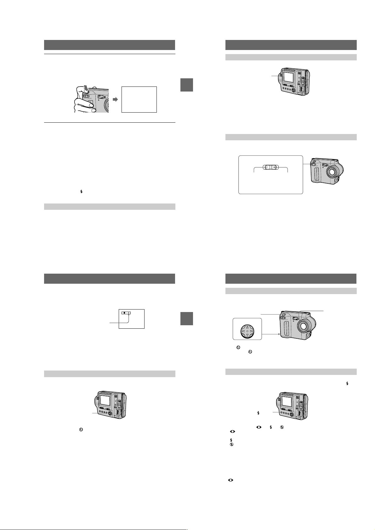
Press the shutter button fully down.
4
The shutter clicks. “RECORDING” appears on the LCD screen, and the image
will be recorded on the floppy disk or the “Memory Stick.” When
“RECORDING” disappears from the LCD screen, you can start the next
recording.
RECORDING
For the number of images you can record on a floppy disk or a
“Memory Stick”
See page 46.
Notes
• When recording bright subjects, the color of the LCD screen may change after the
AE is locked. However, this will not affect the recorded image.
• While the image is being recorded on a floppy disk or a “Memory Stick,” the access
lamp lights. When this lamp is lit, do not shake or strike the camera. Also, do not
turn the poweroff, not change the position of the MS/FD selector,or not remove
the battery pack/floppy disk/“Memory Stick.” Otherwise, an image data breakdown
mayoccurandthefloppydiskorthe“Memory Stick” may become unusable.
• When you press the shutter button fully down at once, the camera starts recording
after the automatic adjustment is complete. However, the recording cannot be
carried out while the lamp (page 8) is flashing. (During this time, the camera is
chargingthe flash.)
Adjusting the brightness of the LCD screen
LCD BACKLIGHT switch
BB
B Recording
B
Adjust the brightness with the [LCD BRIGHT] item in the menu settings (page 45).
This adjustment does not affect the brightness of the images recorded on the floppy disk
or the “Memory Stick.”
To turn off the LCD backlight
Set the LCD BACKLIGHT switch to OFF to save the battery.
Using the zoom feature
Zoom lever
T side: for
telephoto
(subject
appears closer)
W side: for wideangle (subject
appears farther
away)
Checking the last recorded image (Quick Review)
Youcan check the last recorded image by clearing the menu bar from the screen
(page 39) and pressing
Toreturn to the normal recording mode: press the shutter button lightly, or select
[RETURN] with
Todelete the image: first select [DELETE] on the Quick Review screen with
on the control button and press the centerz, and then select [OK] withv/Von the
control button and press the center
on the control button.
b
on the control button and then press the centerz.
b/B
.
z
b/B
Digital zoom function
This camera has a digital zoom function.
Digital zoom enlarges the image by digital processing, and it starts to function when
the zoom exceeds 8×.
T
W
The T-side of the bar shows the
digital zooming zone.
Using digital zoom
• The maximum zoom magnification is 16×.
• Digital zooming deteriorates the picture quality. When digital zoom is not
necessary,set [DIGITAL ZOOM] to [OFF] in the menu settings (page 43).
Note
Digital zoom does not work for moving images.
The indicators on the LCD screen during recording
Press DISPLAY to turn on/off the indicators on the LCD screen. See page 87 for a
detailed description of the indicators.
19
If you cannot get a sharp focus on a close subject
Slide the zoom lever to the W side and move closer to the subject until the focus is
sharp (page 53).
Minimum focal distance to the subject
Wside: About25cm(97/8inches)
T side: About 90 cm (35 1/2 inches)
Torecord even closer subjects, see page 53.
20
Using the self-timer
When you use the self-timer function, the subject is recorded 10 seconds after you
press the shutter button.
Shutter button
BB
B Recording
B
Control button
on the control button, then press the
Select on the LCD screen with
. The (self-timer) indicator appears on the LCD screen, and the subject is
center
z
recorded 10 seconds a fter you press the shu tter button. The self-timer lamp flashes
after you press the shutter button until the image is recorded.
b/B/v/V
Recording images with the flash
The initial setting is AUTO (no indication). In this mode, the flash automatically
strobes when the s urroundings become dark. To change the flash mode, press
(Flash) repeatedly so that the flash m ode indicator appea rs on the LCD scre en.
Self-timer lamp
DISPLAY
Notes
• You cannot turn off the (self-timer) indicator and some of the indicators used in advanced
operations.
• The indicators on the LCD screen are not recorded.
21
1-5
(Flash)
Each time you press the button, the indicator changes as follows.
(No indication)
eye phenomenon.
You can change the amount of the flash light with [FLASH LEVEL] in the menu
settings (page 44).
Notes
• The recommended shooting distance is 0.3 to 2. 5 m (1 to 8 1/3 feet).
• Attaching a conversion lens(not supplied) may block the light from the flash and the recorded
image may be eclipsed.
• You c annot use the built-in flash and an external strobe at the same time .
• Auto red-eye reduction may not produce the desired red-eye reduction effects depending
on individual differences, the distance to the s ubject, if the subject does not see the pre-strobe,
or other conditions.
• The flash effect is not obtained easily wh en you use forced flash in a bright location.
tttt
Auto red-eye reduction : The flash strobes before recording to reduce the red-
Forced flash : The flash strobes regardless of the surrounding brightness.
No flash : The flash does not strobe.
(No indication)
22
B Playback
"b/B"
k)/
Recording moving images
Moving images with audio are recorded in MPEG format.
Torecord moving images, slide the POWER switch to the right to turn on the power
and insert a floppy disk or a “Memory Stick.”
3
1 2
Set the PLAY/STILL/MOVIE selector to MOVIE.
1
Select the recording media using the MS/FD selector.
2
MS: When recording on the “Memory Stick.”
FD: When recording on the floppy disk.
Press the shutter button fully down.
3
“REC” appears on the LCD screen, and the image and sound are recorded on
the floppy disk or “Memory Stick.”
If you press the shutter button momentarily
The image and sound are recordedfor 5 seconds. The recording time can be set
to 10 or 15 seconds with [REC TIME SET] in the menu settings (page 43).
If you hold the shutter button down
The image and sound are recorded while the shutter button is held down for up
to 60 seconds. However,when [IMAGE SIZE] in the menu settings is set to
[320 240], the maximum recording time is 15 seconds (page 46).
Adjusting the brightness of the LCD screen, zooming or using the self-timer
See pages 20 to 22.
LCD screen indicators during recording
Press DISPLAY to turn on/off the indicators on the LCD screen.
These indicators are not recorded. See page 87 for a detailed description of the indicators.
23
Playing back still images
Access lamp
BB
B Recording
B
1
Set the PLAY/STILL/MOVIE selector to PLAY.
1
The last recorded image (still or moving) appears on the LCD screen.
Select the playback media using the MS/FD selector.
2
MS: When playing back images in the “Memory Stick.”
FD: When playing back images in the floppy disk.
Pressvon the control button to display the menu bar on the LCD
3
screen.
Select the desired still image with the
4
control button.
Press
on the LCD screen, then pressb/B.
B"
: Todisplay the preceding image.
"b
:Todisplaythenextimage.
B"
on the control button to select"b/
v/V/b/B
When the menu bar is not displayed
Youcan directly select and play back the image withb/Bon the control button.
Notes
•
Youmight not be able to correctly play back images recorded with this camera on other equipment.
• You may not be able to play back images whose image sizes are larger than the maximum
image size that can be used with this camera for recording.
LCD screen indicators during still image playback
Press DISPLAY to turn on/off the indicators on the LCD screen.
See page 88 for a detailed description of the indicators.
24
2
3, 4
Control button
120min
640
DELETE
INDEX FILE SETUPTOOL
SELECT FILE BACK/NEXT
6/8
Playing back moving images
Access lamp
3–5
2
Control button
1
Set the PLAY/STILL/MOVIE selector to PLAY.
1
The last recorded image (still or moving) appears on the LCD screen.
Select the playback media using the MS/FD selector.
2
MS: When playing back images in the “Memory Stick.”
FD: When playing back images in the floppy disk.
Pressvon the control button to display the menu bar on the LCD
3
screen.
Select the desired moving image with the
4
controlbutton.
Moving images are displayed one size smaller
than still images.
Press
"b/B"
: To display the preceding image.
"b
: To display the next image.
B"
Select theB(playback) button on the
5
LCD screen with
button, then press the center
The moving image and sound are played back.
During playback,
(pause).
on the control button to select
v/V/b/B
on the LCD screen, then pressb/B.
on the control
v/V/b/B
(playback) changes to
B
.
z
X
"b/B"
120min
DELETE
INDEX FILE SETUPTOOL
SELECT
B (playbac
X (pause) button
120min
160
FILE BACK/NEXT
160
To pause playback
SelectX(pause) on the LCD screen withv/V/b/Bon the control button, then press
the center
.
z
When the menu bar is not displayed
Youcan directly select the image withb/Bon the control button, and play back the
image and sound by pressing the center
playback, playback is paused.
z.When you press the center z during
Adjusting the volume
Press VOLUME +/– to adjust the volume.
BB
B Playback
B
LCD screen indicatorsduring moving image playback
Press DISPLAY to turn on/off the indicators on the LCD screen.
See page 88 for a detailed description of the indicators.
6/8
6/8
0:05
DELETE
INDEX FILE SETUPTOOL
SELECT OK
Playback bar
25
26
1-6
Viewing images using a
computer
Youcan view or modify data recorded with your camera using application software
on a computer, or attach it to an E-mail.
Viewingimagesusingafloppydiskdrive
For Windows 98 users
Start up your computer and insert the floppy disk into the disk
1
drive of your computer.
Open [ My Computer] and double-click [ 3 1/2 Floppy (A:)].
2
Double-click the desired data file.
3
Copying a file to the hard disk of your computer before viewing it is
recommended when playing back an audio file or a moving image. If you play
back the file directly from the floppy disk, the image and sound may break off.
Viewing images on a computer connected using the USB cable
This section describes the method for viewing images on a computer using the
supplied USB cable.
What is the USB connection? : Youcan connect the camera to your computer
using the USB cable, to view or modify the images stored in a floppy disk or
“Memory Stick.”
To make the USB connection: You have to install the USB driver in your
computer beforehand.
Be sure to also see the operation manuals for your computer and application
software.
Notes
• Data recorded with your camera is stored in the following formats. Make sure that applications
that support these file formats are installed on your computer.
—Still images (other than TEXT mode, uncompressed mode and Clip Motion): JPEG format
—Moving images/audio: MPEG format
—Uncompressedmode still images: TIFF format
—TEXT mode/Clip Motion: GIF format
• ActiveMovie Player (DirectShow) must be installed (to play back moving pictures).
• QuickTime 3.2 or newer must be installed (to play back moving pictures).
xRecommended computer environment
Recommended Windows environment
OS:Microsoft Windows 98, Windows 98SE, Windows Me, Windows 2000 Professional
The above OS is required to be installedat the factory.
Operation is not assured in an environment upgraded to the operating systems described
above.
CPU:MMX Pentium 200 MHz or faster
The USB connector must be provided as standard.
Recommended Macintosh environment
Macintosh computer with the Mac OS 8.5.1/8.6/9.0
The above OS is required to be installed at the factory.
BB
B Playback
B
However, note that the update to Mac OS 9.0 should be used for the following models with the
Mac OS 8.6 standard installation at the factory:
iMac with a slot loading type CD-ROM drive, iBook, Power Mac G4
The USB connector must be provided as standard.
Notes
• Operations are not guaranteed for either the Windows or Macintosh environment if you connect
two or more USB equipment to a single computer at the same time (except for the USB
keyboard and mouse which are provided as standard), or when using a hub.
• Depending on the type of USB equipment that is used simultaneously, some equipment may
not operate.
• Operations are not guaranteed for all the recommended computer environments mentioned
above.
• Windows and ActiveMovie, DirectShow are either registered trademarks or trademarks of
Microsoft Corporation in the United States and/or other countries.
• Macintosh and Mac OS, QuickTime are either registered trademarks or trademarks of Apple
Computer, Inc.
• All other product names mentioned herein may be the trademarks or registered trademarks of
their respective companies. Furthermore, “™” and “®” arenotmentionedineachcaseinthis
manual.
xInstalling the USB driver
Do not connect your camera to your computer before installing the
USB driver.
First, install the USB driver to the computer. The USB driver is contained together
with application software for viewing images on a CD-ROM which is supplied with
your camera.
If the drive is not recognized properly, see “Troubleshooting” on page 77.
For Windows 98, Windows 98SE, Windows Me and Windows
2000 Professional users
Make sure that the camera is not connected to your computer.
1
Do not connect the USB cable in this step.
Turn on your computer and allow Windows to load.
2
Insert the supplied CD-ROM in the CD-ROM drive of your computer.
3
The applicationsoftware screen appears.
Click “USB Driver Installation for Windows 98/98SE, Windows Me,
4
Windows 2000”.
USB driver installation starts.
Follow the on-screen messages to install the USB driver.
5
If the message appears after the installation to verify that you restart the
computer, restart the computer.
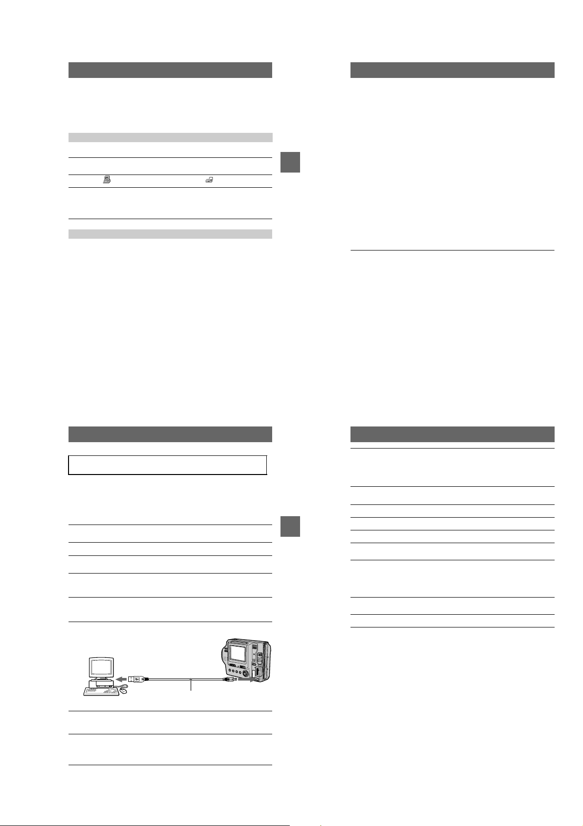
Connect the USB jack (mini-B) on your camera with the USB
6
connector on your computer using the supplied USB cable.
To t he U SB
connector
Computer
Insert a floppy disk or a “Memory Stick” into your camera, and set
7
the MS/FD selector to the appropriate position according to the
media inserted.
Connect the AC power adaptor and turn on your camera.
8
“USB MODE ” appears on the LCD screen of your camera and the camera is set
to communication standby mode. Yourcomputer recognizes the camera, and
the WindowsAdd Hardware Wizardstarts.
To the USB
jack
USB cable
Push the connector
as far as it will go
27
28
Follow the on-screen messages to recognize the hardware.
9
The Add Hardware Wizard starts twice because two different USB drivers are
installed. Be sure to allow the installation to complete without interrupting it.
If the message appears after the installation to verify that you restart the
computer, restart the computer.
For Macintosh users
Turn on your computer and allow the Mac OS to load.
1
Insert the supplied CD-ROM in the CD-ROM drive of your computer.
2
Double-click the CD-ROM drive icon to open the window.
BB
B Playback
B
3
Double-click the icon of the hard disk containing the “System
4
Folder” to open the window.
Move the following two files from the window opened in step3to
5
the “System Folder” icon in the window opened in step
and drop).
• Sony USB Driver
• Sony USB Shim
When “Put these items into the Extensions folder?” appears, click
6
“OK.”
Restart your computer and connect the USB cable.
7
(drag
4
29
30
1-7
xViewing images
For Windows 98, Windows 98SE, Windows Me and Windows
2000 Professional users
Turnon the power of your computer and allow Windows to load.
1
Connect one end of the supplied USB cable to the USB jack (mini-
2
B) on the camera and the other end to the USB connector on your
computer.
To t he U SB
connector
Computer
Insert a floppy disk or “Memory Stick” into your camera, and set
3
the MS/FD selector to the appropriate position according to the
media inserted.
Connect the AC power adaptor to your camera and then to a wall
4
outlet (mains) and turn on the power of your camera.
“USB MODE” appears on the LCD screen of the camera.
Open “My Computer” on Windows and double-click the newly
5
recognized drive, “Removable Disk”(Example (D:)
The folders inside the floppy disk or “Memory Stick” are displayed.
If the drive is not recognized properly, see “Troubleshooting” on page 77.
∗ Drive identifier depends on your computer.
To the USB
jack
USB cable
Push the connector
as far as it will go
∗
).
Select and double-click the desired image/audio file from the
6
folder.
For the detailed folder and file name, see “Image file storage destinations and
image file names” (page 34).
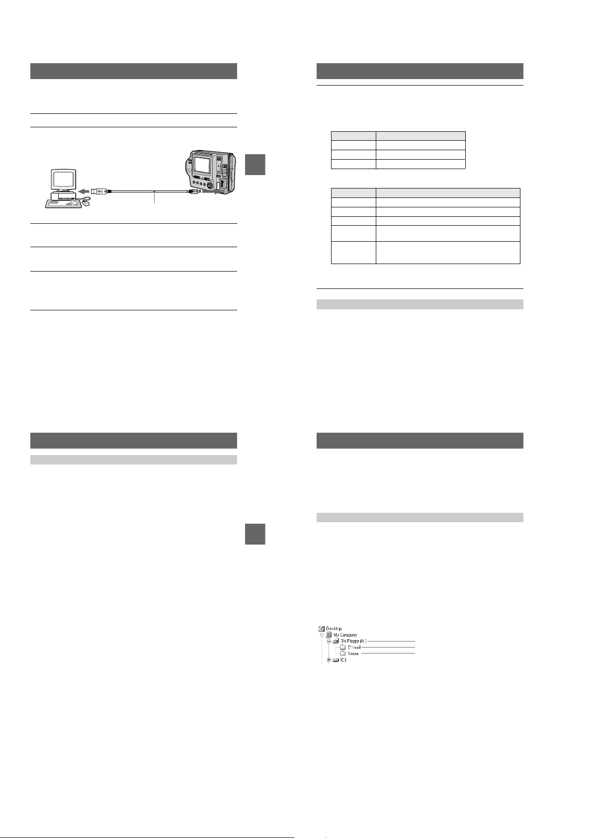
When viewing an image in a floppy disk
Desired file type
Audio* “Voi ce” foldertAudio file*
E-mail image “E-mail” folder
Other files Image file
BB
B Playback
B
When viewing an image in a “Memory Stick”
Desired file type
Still image “Dcim” foldert“100msdcf” foldertImage file
Moving image* “Mssony” folder
Audio* “Mssony” folder
Clip Motion
image
E-mail image
TIFF image
(uncompressed)
∗ Copying a file to the hard disk of your computer before viewing it is recommended. If
you play back the file directly from the floppy disk or “Memory Stick,” the image and
sound may break off.
For Windows Me or Windows 2000 Professional users
When using Windows Me or Windows 2000 Professional, the following procedures
are recommended when disconnecting the USB cable from your computer, ejecting
the floppy disk or “Memory Stick” from the camera, or changing the position of the
MS/FD selector, while it is connected to your computer.
Stop the drive by clicking on the “Unplug/Eject” icon in the task tray.
1
Carry out the operation after the message, confirming the safe removal of the
2
hardware, appears.
Double-click in this order
Double-click in this order
“Dcim” folder
“Mssony” folder
t
Image file
t
“Moml0001” foldertImage file*
t
“Momlv100” folder
t
“100msdcf” foldertImage file
t
“Imcif100” foldertImage file
t
Audio file*
31
Notes on using your computer
Floppy disk/“ Mem ory Stick”
• Format the floppydisk or “Memory Stick” only using this camera
(page 70). You cann ot format the floppy disk or “Memory Stick” using
a computer via the USB cable.
• Use only a DOS/V 2HD format floppy disk. Other disks will not be recognized by a
computer.
• Do not optimize the “Memory Stick” on a Windows machine. This will shorten the
“Memory Stick” life.
• Do not compress the data on the floppy disk or “Memory Stick.” Compressed files
cannot be played back on your camera.
Software
• Depending on your application software, the file size may increase when you open
a still image file.
• When you load an image modified using the supplied retouching software from
your computer to the camera or when you directly modify the image on the camera,
the image format will differ so the “FILE ERROR” message may appear and you
maybeunabletoopenthefile.
• Depending on your application software, only the first frame of a Clip Motion
image may be displayed.
Communications with your computer
Communications between your camera and your computer may not recover after
recovering from Standby or Sleep.
Other
When connecting the camera to a computer or when using an external power source,
remove the battery pack from inside the camera.
32
Image file storage destinations
and image file names
Image files recorded with your camera are grouped in folders by recording mode.
Images in a floppy disk and ones in a “Memory Stick” have differentfile names. The
meanings of the file names are as follows.
When using floppy disks
stands for any number within the range from 001 to 999.
sss
stands for one of the following characters below.
BB
B Playback
B
f
S: Still image file recorded at 640 480 size
F: Still image file of more than 640 480 size
V: Moving image file recorded at 160 112 size
W: Moving image file recorded at 320 240 size
T: Still image file recorded in TEXT mode
C: Clip Motion file recorded in NORMAL mode
M: Clip Motion file recorded in MOBILE mode
For Windows 98 users (The drive recognizing the floppy disk is
[A].)
Storage destination containing still image,
moving image, TEXT mode image and Clip
Motion image data
Folder containing E-mail mode image data
Folder containing VOICE mod e audio data
33
34
1-8
Location File Meaning
3 1/2 Floppy
[A:]
E-mail fold er MVC-
Voice folder MVC-
• The numerical portions of the following files are the same.
—An image file recorded in E-MA IL mode and its corresp onding small-size image file
—An audio file recorded in VOICE mode and its correspondin g image file
—An image file recorded in TEXT mode and i ts corresponding index image file
—An image file recorded with Clip Mot ion and its corresponding index image file
INDEXdisplay files other than the TEXT modeand Clip Motionfiles are played back onlyon this
•
camera.
MVC-
MVC-
MVC-
MVC-
MVC-
.JPG • Still image file recorded normally
sssf
sssf
sssf
sssf
sssf
sss
sss
• Still image file recorded in
— E-MAIL mode (page 49)
— VOICE mode (page 50)
.411 • INDEX display file
Thisfilecanonlybeplayedbackon
your camera.
.MPG • Moving image file
.GIF • Still image file recorded in
— TEXT mode (page 51)
— Clip Motion (page 47)
.THM • Index im age file recorded in
— TEXT mode (page 51)
E.JPG • Small-size image file recorded in E-
A.MPG • Audio file recorded in VOICE mode
— Clip Motion (page 47)
MAIL mode (page 4 9)
(page 50)
When using “Memory Stick”s
stands for any number within the range from 0001 to 9999.
ssss
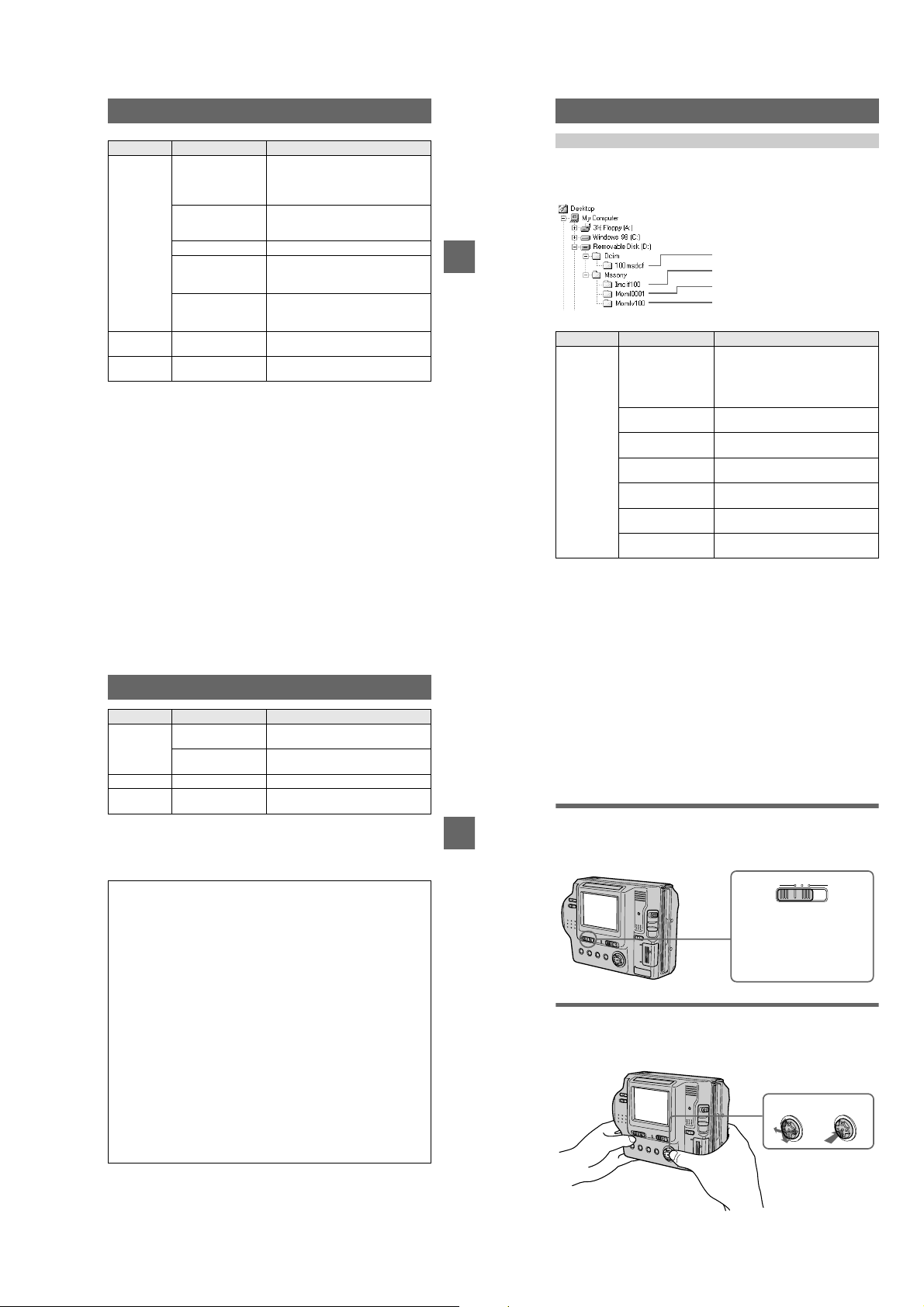
For Windows 98 users (The drive recognizing the camera is
“D.” )
Folder containing still image recorded in
normal mode, TEXT mode image and Clip
Motion image data
BB
B Playback
B
Folder containing E-MAI L mode and TIFF
mode image data
Folder containing movi ng image data
Folder containing VOICE mode audio data
Folder File Meaning
100msdcf DSC0
CLP0
CLP0
MBL0
MBL0
TXT0
TXT0
.JPG • Still image file recorded normally
ssss
ssss
ssss
ssss
ssss
ssss
ssss
• Still image file recorded in
— E-MAIL mode (page 49)
— TIFF mode (page 52)
— VOICE mode (page 50)
.GIF • Clip Motion file recorded in NORMAL
mode (page 47)
.THM • Index image file of Clip Motion file
recorded in NORMAL mode
.GIF • Clip Motion file recorded in MOBILE
mode (page 47)
.THM • Index image file of Clip Motion file
recorded in MOBILE mode
.GIF • Still image file recorded in TEXT mode
(page 51)
.THM • Index image file of still image file
recorded in TEXT mode
Folder File Meani ng
Imcif100 DSC0
DSC0
Moml0001 MOV0
Momlv100 DSC0
The numerical portions of the foll owing files are the same.
—A small-size image file recorded in E-MAIL mode and its corresponding image file
—An uncompressed image file recorded in TI FF mode and its corresponding i mage file
—An audio file recorded in VOICE mode and its correspondin g image file
—An image file recorded in TEXT mode and i ts corresponding index image file
—An image file recorded with Clip Mot ion and its corresponding index image file
Tips
The digital still camera saves recorded images as digital data. The format of the
saved data is called as the file format. The formats that can be used with this
camera are as follows:
JPEG format
Most digital still cameras, operating systems of computers, and browser software
adopt this format. This format is able to compress files without appreciable
deterioration. However, if the image is compressed an d saved on repeated
occasions, the image will deteriorate. Thi s camera records still images using the
JPEG format for nor mal recording.
GIF format
Using this format, the image will not deteriorate even if the image is compressed
and saved on repeated occasions. This format limits the number of colors to 256
colors. This camera records still images using the GIF format in Clip Motion
(page 47) or TEXT mode (pa ge 51).
TIFF format
Stores shooting images without compression, so the image does not deteriorate.
Most of operating systems and applications correspond to thisformat. This camera
records still image s using the TIFF format for the TIFF mode (page 52).
MPEG format
This format is very typical for moving images. This camera records audio using
the MPEG format for the moving images recording and the VOICE mode
(page 50).
.JPG • Small-size image file recorded in E-
ssss
ssss
ssss
ssss
MAIL mode (page 4 9)
.TIF • Uncompressed image file recorded in
TIFF mode (page 52)
.MPG • Moving image file recorded normally
.MPG • Audio file recorded in VOICE mode
(page 50)
35
36
Advanced operations
Before performing advanced
operations
This section describes the basic control methods that are frequently used for
“Advanced operations.”
How to use the PLAY/STILL/MOVIE selector
The PLAY/STILL/MOVIE selector selects whether you can use your camera to
BB
B Playback
B
record or play back and edit images. Set the selector as follows before starting to
operate your camera.
PLAY STILL MOVIE
PLAY: To play back or edit
images
STILL: To record still images,
VOICE images and Clip
Motion images
MOVIE: To record moving
images
How to use the control button
The control button is used to select the buttons, images and menus displayed on the
LCD screen of your camera and modify the settings. The operation methods that are
frequentlyusedfor“Advanced operations” are described below.
Select
Set (enter)
37
38
1-9
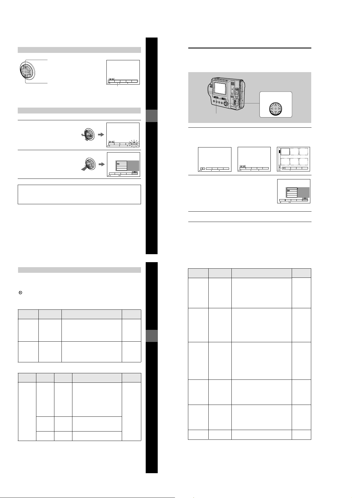
Turning on/off the operation buttons (menu bar) on the LCD screen
Press v to display the menu bar
on the LCD screen.
DELETE
INDEX FILE SETUPTOOL
Press V to clear the menu bar
from the LCD screen.
Note
You cannot clear the menu bar on the IN DEX screen (page 59).
SELECT OK
Menu bar
MENU BAR OFF
How to change the menu settings
Some of the advanced operations for your camera are executed by selecting menu
itemsdisplayedontheLCDscreenwiththecontrolbutton.
1–3
Control button
Selecting items or images on the L CD screen
Pressv/V/b/Bon the control
1
button to select the item you
want to set or the image you
want to display.
The color of the selected item or the
frame of the selected image
changes from blue to yellow.
Press the centerzto enter
2
the item.
Repeat steps
each function.
1
and2to execute
DELETE
INDEX FILE SETUPTOOL
SELECT OK
VIDEO OUT
/LANGUAGE
CLOCK SET
BEEP
LCD BRIGHT
DELETE
INDEX FILE SETUPTOOL
SELECT CLOSE
MENU BAR OFF
The “Advanced operations” section of this manual refers to
selecting and entering items by the above procedure as
“Select [item name].”
Menu settings
Menu items that can be modified differ depending on the positions of the PLAY/
STILL/MOVIE selector or the MS/FD selector. The LCD screen shows only the
items you can operate at the moment. Initial settings are indicated with
(self-timer)
Records with the self-timer (page 22).
EFFECT
Item Setting Description
P. EFFECT SOLAR IZE
DATE/
TIME
B&W
SEPIA
NEG.ART
OFF
x
DAY &
TIME
Sets the image special effects (page 58). STILL
Sets whether to insert the date and time
into the image (page 58).
DATE
OFF
x
FILE
Item-1 Item-2 Setting Description
DISK
TOOL
(When the
MS/FD
selector is
set to FD.)
FORMAT OK Formats a floppy disk (page 70).
CANCEL Cancels formatting of a floppy
DISK
OK Copies all data stored in a floppy
COPY
Once you format a floppy disk,
all of the data, including
protected images are deleted. Be
sure to check for images before
you format a floppy disk.
disk.
disk to another disk (page 68).
CANCEL Cancels the disk copy.
CANCEL Goes back to the [DISK TOOL]
item.
.
x
PLAY/STILL/
MOVIE selector
MOVIE
STILL
PLAY/STILL/
MOVIE
PLAY
STILL
MOVIE
selector
39
Before performing advanced operations
Before performing advanced operations
PLAY/STILL/MOVIE selector
Pressvon the control button to display the menu bar.
1
The menu bar appears as follows according to the position of the PLAY/STILL/
MOVIE selector.
STILL/MOVIE
EFFECT FILE SETUP
CAMERA
SELECT OK
Select the desired item withv/V/b/Bon the
2
control button, then press the center
The color of the selected item changes from blue to
yellow, and when you press the center
that can be set for its item are displayed.
Note
The displayed items are changed according to the position
of the MS/FD selector.
Select the desired setting withv/V/b/Bon the control button, then
3
press the center
MENU BAR OFF
z
PLAY (single mode)
INDEX FILE SETUPTOOL
SELECT OK
.
DELETE
, the settings
z
MENU BAR OFF
.
z
PLAY (INDEX mode)
2001 7 4 10:30PMMVC–001F
DELETE
FILE SETUPTOOL
SELECT SINGLE DISPLAY
VIDEO OUT
/LANGUAGE
CLOCK SET
BEEP
LCD BRIGHT
DELETE
INDEX FILE SETUPTOOL
SELECT OK
NTSC
To cancel the setup
PressVon the control button repeatedly until the LCD screen returns to the menu bar
display in step
1
. To clear the menu bar, pressVagain.
40
Item Setting Description
FORMAT
(When the
MS/FD
selector is
set to MS.)
FILE
NUMBER
CLIP
MOTION
OK Formats a “Memory Stick.” Once you
CANCEL Cancels formatting of a “Memory
SERIES Assigns numbers to files in sequence
NORMAL Resets the file number that starts from
x
160×120
(NORMAL)
80×72
(MOBILE)
format the “Memory Stick,” all of the
data, including protected images are
deleted. Be sure to check for images
before you format a “Memory Stick.”
Stick.”
even if the floppy disk or “Memory
Stick” is changed. Note that file
numbers are not in sequence between a
floppy disk and “Memory Stick.”
001 or 0001 each time the floppy disk or
“Memory Stick” is changed.
Sets the image size and number of
frames for creating GIF format
animation (page 47).
Up to 10 frames can be recorded.
Up to 2 frames c an be recorded.
CANCEL Cancels Clip Motion.
IMAGE
SIZE
(When the
MS/FD
selector is
set to FD.)
IMAGE
SIZE
(When the
MS/FD
selector is
set to MS.)
IMAGE
SIZE
1472× 1104
x
1280× 960
1280(3:2)
1024×768
640×480
1472 (FINE)
x
1280 (FINE)
1280(3:2) F
1024 (FINE)
640 (FINE)
320×240
160×112
x
Selects the image size when recording
still images.
Selects the image size when recording
still images.
Selects the MPEG image size when
recordingmovingimages.
PLAY/STILL/
MOVIE
PLAY
STILL
MOVIE
STILL
MOVIE
STILL
STILL
STILL
MOVIE
selector
41
42
1-10
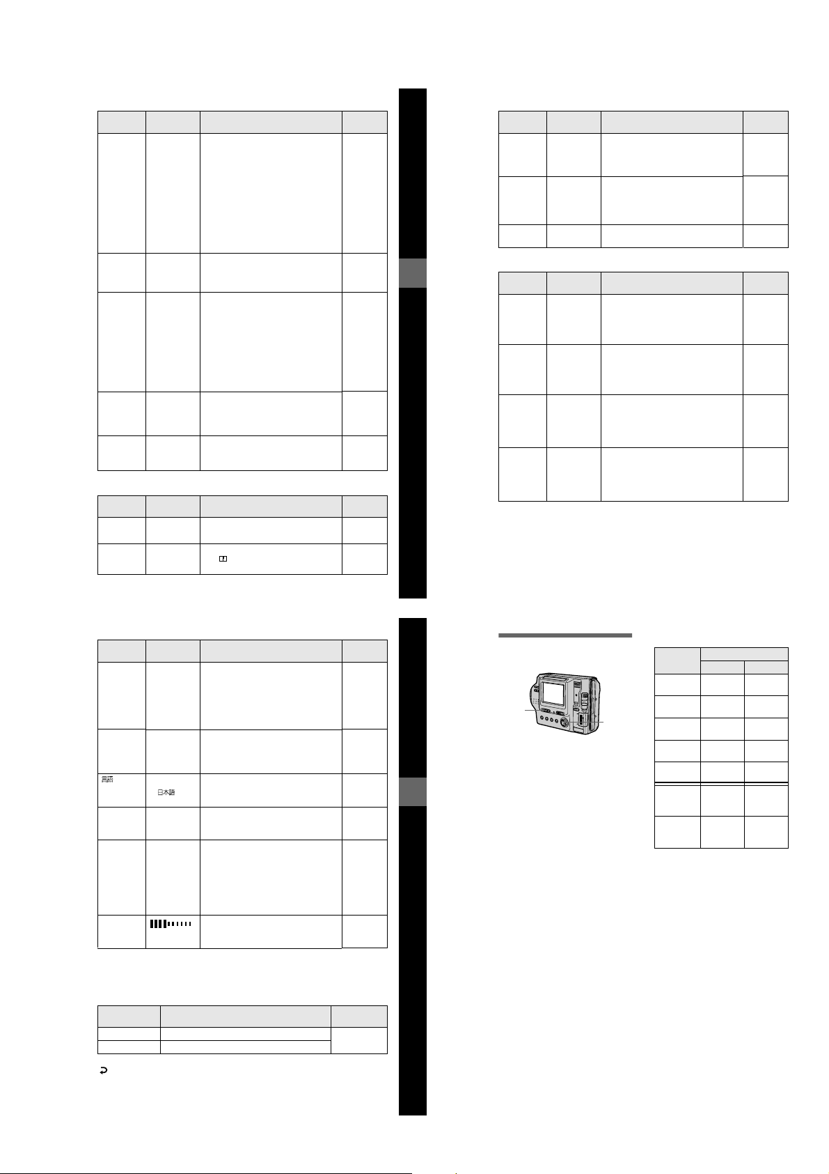
Item Setting Description
REC MODE TIFF Records a TIFF (uncompressed) file in
TEXT Records a GIF file in black-and-white.
VOICE Records an audio file (with a still image)
E-MAIL Records a small-size (320 240) JPEG
NORMAL Records an image using the normal
x
REC TIME
SET
SLIDE
SHOW
(Only in
PLAY
(single)
mode)
PRINT
MARK
PROTECT ON Protects images against accidental
15 sec Selects the recording time for moving
10 sec
5sec
x
INTERVAL
REPEAT A slide show can be repeated. (When
START Starts the slide show.
CANCEL Cancels the slide show settings or
ON Marks the still images to be printed
OFF Unmarks the print mark of the still
x
OFF Releasesprotection of images.
x
addition to the JPEG file when the MS/
FD selector is set to MS.
in addition to the JPEG file.
file in addition to the selected image
size.
recording mode.
images.
Sets the slide show interval.
3 sec/5 sec/10 sec/30 sec/1 min
x
using the floppy disk, a slide show is up
to approx. 20 minutes)
ON/OFF
x
execution.
(page 69).
images.
erasure (page 63).
CAMERA
Item Setting Description
DIGITAL
ZOOM
SHARPNESS
ON Uses digital zoom. STILL
x
OFF Does not use digital zoom.
+2 to –2 Adjusts the sharpness of the image.
The indicator appears (exceptwhen
the setting is 0).
PLAY/STILL/
MOVIE
selector
STILL
MOVIE
PLAY
PLAY
PLAY
PLAY/STILL/
MOVIE
selector
STILL
43
Before performing advanced operations
Item Setting Description
WHITE
BALANCE
FLASH
LEVEL
EXPOSURE +2.0EV to
IN DOOR
OUT DOOR
HOLD
AUTO
x
HIGH Makes the flash level higher than
NORMAL Normal setting.
x
LOW Makes the flash level lower than normal.
–2.0EV
Sets the white balance (page 57). STILL
normal.
Adjusts the exposure before recording. STILL
TOOL
Item Setting Description
FD
COPY
(When the
MS/FD
selector is
set to FD.)
COPY
(When the
MS/FD
selector is
set to MS.)
RESIZE
(When the
MS/FD
selector is
set to FD.)
RESIZE
(When the
MS/FD
selector is
set to MS.)
t
FD Copies the image to a floppy disk. PLAY
t
MS Copiesthe image to a “Memory Stick.”
FD
CANCEL Cancels copying of the image (page 66).
MS
t
MS Copies the image to a “Memory Stick.” PLAY
t
FD Copies the image to a floppy disk.
MS
CANCEL Cancels copying of the image (page 66).
1472 1104
1280 960
1024 768
640 480
CANCEL
1472 (FINE)
1280 (FINE)
1024 (FINE)
640 (FINE)
CANCEL
Changes the recorded image size in
PLAY (single) mode (page 65).
Changes the recorded image size in
PLAY (single) mode (page 65).
44
PLAY/STILL/
MOVIE
MOVIE
STILL
MOVIE
PLAY/STILL/
MOVIE
PLAY
PLAY
selector
selector
SETUP
Item Setting Description
DEMO
VIDEO
OUT
LANGUAGE
CLOCK
SET
BEEP SHUTTER Turnson the shutter sound only. (The
LCD
BRIGHT
STBY/ON
x
OFF
NTSC Sets the video output signal to NTSC
PAL Setsthe video output signal to PAL
/
ENGLISH Displays the menu items in English. PLAY
x
— Sets the date and time (page 14). PLAY
ON Turns on the beep/shutter sound (when
x
OFF Turns off the beep/shutter sound.
Displayed only when you use the AC
power adaptor in STILL or MOVIE
mode. When [ON] is selected, a
demonstration will start if you do not
operate your camera for about 10
minutes. To stop the demonstration, turn
off your camera.
mode (e.g., Japan, the USA).
mode (e.g., Europe).
/JPN Displays the menu items in Japanese.
shutter sound is heard when you press
the shutter button.)
you press the control button/shutter
button).
Adjusts the LCD screen brightness
using +/- on the LCD screen.
INDEX (Only in PLAY (single) mode)
Displays six images at a time (PLAY (INDEX) mode).
DELETE (Only in PLAY (single) mode)
Setting Description
OK Deletes the displayed image. PLAY
CANCEL Cancels deleting of the image.
PLAY/STILL/MOVIE
(Return) (Only in PLAY (INDEX) mode)
Returns to PLAY(single) mode.
PLAY/STILL/
MOVIE
selector
STILL
MOVIE
PLAY
STILL
MOVIE
STILL
MOVIE
STILL
MOVIE
PLAY
STILL
MOVIE
PLAY
STILL
MOVIE
selector
45
Various recording
B
Setting the image size
(IMAGE SIZE)
1
2, 3
Set the PLAY/STILL/MOVIE
1
selector to STILL or MOVIE.
Select [FILE] and then
2
[IMAGESIZE] from the menu.
Select the desired image size.
Before performing advanced operations
3
Still image size:
• When the MS/FD selector is set
to FD
1472 1104, 1280 960,
1280 (3:2)*, 1024 768, 640 480
• When the MS/FD selector is set
to MS
1472 (FINE), 1280 (FINE),
1280 (3:2)F*, 1024 (FINE),
640 (FINE)
(FINE): The quality of the image
recorded in a “Memory Stick” is
higher than the image recorded in a
floppy disk even if the image size is
same. Also, the file size recorded in a
“Memory Stick” is larger than the file
recorded in a floppy disk.
∗ The image is recorded in the ratio of
three to two to fit the printing paper
size. Using this image size, the
margin of an image is not printed out.
However,the slight amount of the
upper and lower of the image being
displayed on the LCD screen is not
recorded.
Moving image sizes:
320 240, 160 112
The number of images or the time
that you can record on a floppy
disk or “Memory Stick” (8 MB)
Image size
1472 1104 Approx. 5 Approx.
1280 960 Approx. 6 Approx.
1280 (3:2) Approx. 6 Approx.
1024 768 Approx.10Approx.
∗ When REC MODE is set to NORMAL.
∗∗The maximum recording time in
Notes
• If you try to record 55 images or more on a
floppy disk, even if the remaining disk
capacity is sufficient, “DISK FULL”
appears on the LCD screen and you cannot
record any more images.
• If you try to record 3001 images or more
on a “Memory Stick,” even if the
remaining memory capacity of the
“Memory Stick” is sufficient, “NO
MEMORYSPACE” appears on the LCD
screen and you cannot record any more
images.
Number of images or time*
Floppy disk
640 480 Approx.30Approx.
320 240 Approx.
160 112 Approx.
continuous recording
15 sec
60 sec
“Memory Stick”
10
12
12
20
48
Approx.
80 sec
(15 sec)**
Approx.
320 sec
(60 sec)**
46
1-11
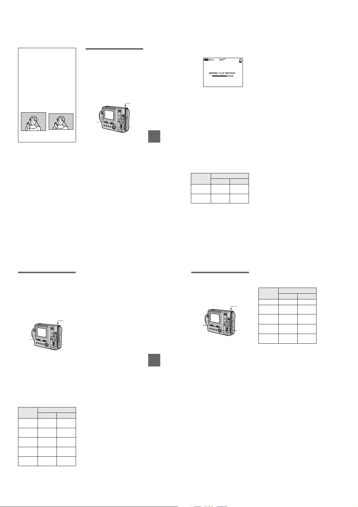
Tips
The size of the image is in dicated by the
pixel unit. The higher the number of
pixels, the more information is included.
So, an image that is saved usi ng a large
number of pixels is suitable for a l argeformat print and one that is saved using a
smallernumberofpixelsissuitablefor
attaching to an E-mail.Normally, an
image is recorded in the ra tio of four to
three to fit the monitor ratio. This camera
canalsorecordtheimageintheratioof
three to two to accommodate t he most
common printing paper size. This i s the
sameratioastheoneusedinphotodeveloping shops.
1280×960
1280 (3:2)
Creating Clip Motion
Files
Clip Motion is an animation function
that plays back still images in
succession. Clip Motion images are
playedbackonthiscameraat
approximately 0.5 s intervals. The
images are stored in GIF format, which
is convenient for creating home pages
or attaching images to an e-mail.
4, 5
1
2, 3
Set the PLAY/STILL/MOVIE
1
selector to STILL.
Select [FILE] and then [CLIP
2
MOTION] from the menu.
Select the desired mode.
3
160×120 (NORMAL)
Clip Motion of up to 10 frames can
be recorded.
This is suitable for use on h ome
pages, etc.
80×72 (MOBILE)
Clip Motio n of up to 2 frames c an
be recorded.
This is suitable for use with
portable data terminals.
CANCEL
This cancels the creation of Clip
Motion.
BB
B Various recording
B
Record the image for the first
4
frame.
Record the image for the next
5
frame.
Image recording can b e repeated
up to the maximum number of
recordable frames.
The frame images are
automatically recorded on the
floppy disk or “Memory Stick”
when you select [FINISH] or after
recording the maximum number of
frames.
6
160
2/10
To stop Clip Motion creation
Select [RETURN] after step 3.
Note that ifyou record even oneframe,
youcannotstopClipMotioncreation.
The number of Clip Motion frames
that you can record on a floppy
disk or “Memory Stick” (8 MB)
Image size Number of images
Floppy disk
160×120
(NORMAL)
80×72
(MOBILE)
∗ When recording 10 frames per Clip
Motion file
∗∗When recording 2 frames per Clip
Motion file
“Memory Stick”
Approx.7*Approx.
Approx.
54**
40*
Approx.
400**
Notes
• Reading and writing data takes more time
than normal image recording.
• Due to the limitations of the GIF form at,
the number of colors for Cl ip Motion
images is reduced to 256 colors or less.
Therefore, the pic ture quality may
deteriorate for some im ages.
• ThefilesizeisreducedinMOBILEmode,
so the picturequality deteriorates.
• GIF files not created on this camera may
not be displayed correctly.
Recording still
images for e-mail (EMAIL)
TheE-MAILmoderecordsasmallsize (320×240) image at the same time
as a still image. Small-size images are
convenient for e-mail transmission,
etc. Images in E-MAIL mode are
recorded in the JPEG format.
3
1
2
Set the PLAY/STILL/MOVIE
1
selector to STILL.
Select [FILE], [REC MODE],
2
andthen[E-MAIL]fromthe
menu.
Record the image.
3
The number of images that you
can recordonafloppydiskor
“Memory Stick” (8 MB) in E-MAIL
mode
Image size Number of images
1472×1104 Approx. 4 Approx .
1280×960 Approx. 5 Approx.
1280 (3:2) Approx. 5 Approx.
1024×768 Approx. 8 Approx.
Floppy disk
640×480 Approx.22Approx.
“Memory Stick”
10
12
12
20
44
To retu rn to norma l
recording mode
Select [NORMAL] in step 2.
47
BB
B Various recording
B
48
Adding audio files to
still images (VOICE)
Images in VOICE mode are recorded
in the JPEG format, and audio is
recorded in the MPEG format.
3
1
2
Set the PLAY/STILL/MOVIE
1
selector to STILL.
Select [FILE], [REC MODE],
2
andthen[VOICE]fromthe
menu.
Record the image.
3
If you press and release the
shutter button, sound is
recorded for five seconds.
Ifyouholddowntheshutter
button, sound is recorded until
you release the shutter button for
up to 40 seconds.
The number of images that you can
record on a floppy disk or
“Memory Stick” (8 MB) in VOICE
mode
Image size Number of images*
1472×1104 Approx . 3 Approx. 9
Floppy disk
1280×960 Approx. 4 Approx.
1280 (3:2) Approx. 4 Approx.
1024×768 Approx. 6 Approx.
640×480 Approx.12Approx.
∗ When recording 5-second audio.
To return to no rmal
recording mode
Select [NORMAL] in step 2.
“Memory Stick”
11
11
17
34
49
50
1-12
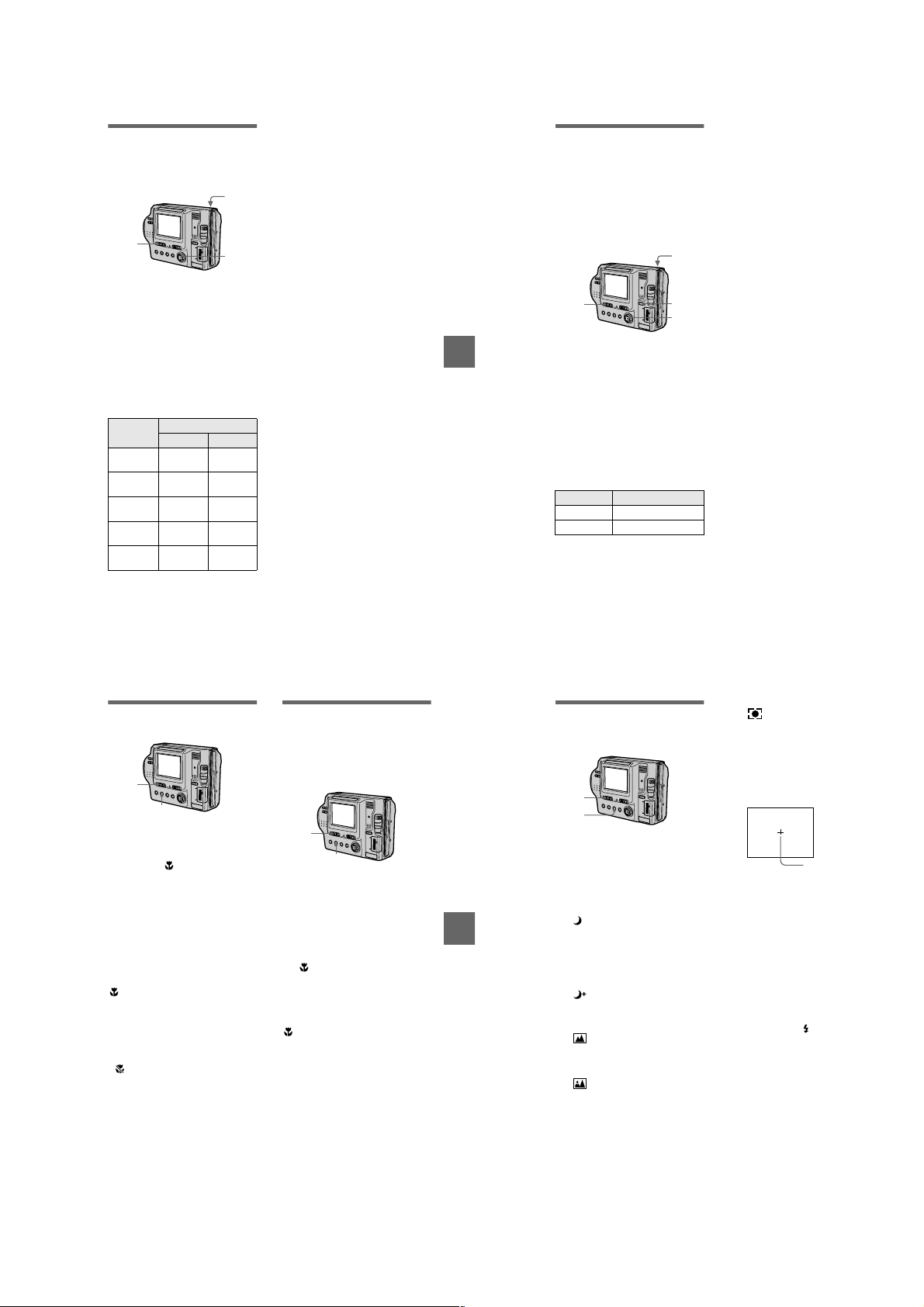
Recording text
documents (TEXT)
Text is recorded in GIF fo rmat to
provide a clear image.
3
1
2
Set the PLAY/STILL/MOVIE
1
selector to STILL.
Select [FILE], [REC MODE],
2
andthen[TEXT]fromthe
menu.
Record the image.
3
The number of images that you
can recordonafloppydiskor
“Memory Stick” (8 MB) in TEXT
mode
Image size Number of images*
1472×1104 Minimu m5Minimum
1280×960 Minimu m7Minimum
1280 (3:2) Minimum8Minimum
1024×768 Minimu m11Minimum
∗ The maximum number of recordabl e
images depends on the document
condition, such as the amo unt of text
portions.
640×480
Floppy disk
“Memory Stick”
29
40
44
Minimum28Minimum
61
160
To retu rn to norma l
recording mode
Select [NORMAL] in step 2.
Notes
• If thesu bject isnot evenly illuminated, you
may be unable to record a clear image.
• Writing and reading data take more time
than normal recording.
BB
B Various recording
B
Recording still
images as
uncompressed files
(TIFF)
This mode simultaneously records still
images in both TIF F format
(uncompressed) and JPEG format
(compressed) when using a “Memory
Stick.”
4
1
2
3
Set the PLAY/STILL/MOVIE
1
selector to STILL.
Set the MS/FD selector to MS.
2
Select [FILE], [REC MODE],
3
and then [TIFF] from the
menu.
Record the image.
4
The number of images that you
can record on a “Memory Stick”
(8 MB) in TIFF mode
Image size Number of images
1280×960 1
1280 (3:2) 1
To retu rn to norma l
recording mode
Select [NORMAL] in step 2.
Notes
• JPEG images are recorded in the image
size selected by the [IMAGE SIZE] menu
(page 46). TIFF images are recorded in
[1280×960] size other than when [1280
(3:2)F] is selected.
• Writing data takes more time than in
normal recording.
Recording images in
macro
1
2
Set the PLAY/STILL/MOVIE
1
selector to STILL or MOVIE.
Press FOCUS repeatedly
2
until the (macro) indicator
appears on the LCD screen.
With the zoom lever set to the W
side, you can shoot a subjectthat is
about 3 cm (1 3/16 inch) away
from the lens surface in macro
mode.
T o re turn to normal
recording mode
Press FOCUS repeatedly until both the
9
indicators disappear.
and
Notes
• You cannot record images in macro with
the following PROGRAM AE modes:
—Landscape mode
—Panfocus mode
• You cannot record images in macro if the
indicator appears.
51
Setting the distance
to the subject
Normally the focus is automatically
adjusted. This function is useful when
the auto focus does not work well such
as in dark places .
1
2
Set the PLAY/STILL/MOVIE
1
selector to STILL or MOVIE.
Press FOCUS repeatedly
2
untilasharpfocusis
achieved.
9
The
(manual focus) indicator
appears on the LCD screen. You
can select from six f ocus settings:
(macro), 0.5 m , 1.0 m, 3.0 m ,
7.0 m, and ∞ (infinity)
To reactivate auto focusing
Press FOCUS repeatedly until both the
9
indicators disappear.
and
Notes
• Focal point information may not
completely show the correct distance. Use
the information as a guide.
• Focal point information does not show the
correct distance when attaching the
conversion lens.
• If you shoot a subject within 0.9 m
(35 1/2 inches) whi le the zoom lever is set
to T side, you cannot get a clear focus. In
such cases, the focal point information
flashes. Move the zoom leverto the W side
until the indicator stops fl ashing.
• You c annot use this function if you have
selected the Panfocus mode in the
PROGRAM AE function.
BB
B Various recording
B
52
Using the PROGRAM
AE function
1
2
Set the PLAY/STILL/MOVIE
1
selector to STILL or MOVIE.
Press PROGRAM AE
2
repeatedly to select the
desired PROGRAM AE mode.
Twilight mode
Suppresses the blurring of colors
of a bright su bject in a dark place
so that you can record the subject
without losingthe dark atmosphere
of the surroundings.
Twilight plus mode
Increases the effectiveness of the
twilight mode function.
Landscape mode
Focuses only ona distant subject to
record landscapes, e tc.
Panfocus mode
Changes the focus quickly and
simply from a close subject to a
distant subject.
Spot light-metering mode
Select this mode whe n there is
backlight or when there is strong
contrast between the subject and
the background, etc. Po sition the
point you want to record at the spot
light-metering cross hair.
LCD screen
Spot light-metering
cross hair
T o cancel PROGRAM AE
Press PROGRAM AE repeatedly until
the indicator o n the LCD sc reen goes
out.
Notes
• You can focus only on distant s ubjects in
Landscape mode.
• In Panfocus mode, the zoom position is set
to the W side and focus is fixed.
• When you record in Twilight plus mode,
we recommendthat you use a tripodto
prevent shaking.
• Set the forced flash w hen you use the
flash in the following modes:
– Twilight mode
– Twilight plus mode
– Landscapemode
• You cannot use the PROGRAM AE
function when [REC MODE] is set to
[TEXT].
53
54
1-13
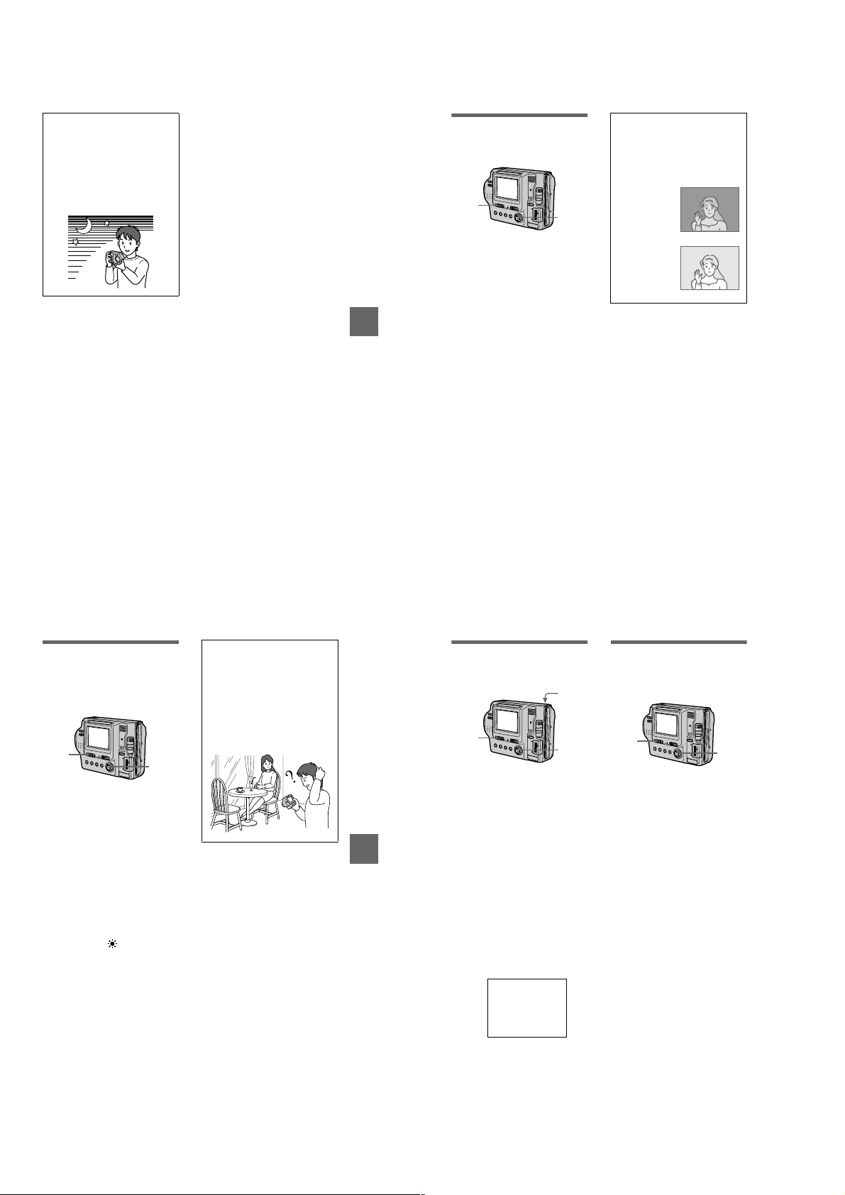
Tips
Under normal recording condition s, the
camera automatically makes various
adjustments, such as tho se for the focus,
iris, exposure, and white balance, as it
shoots. However, you may not be able to
carry out your desired shooting
depending on shooting conditions. The
program AE function provides you with
near-optimum adjustments to suit your
shooting situation.
BB
B Various recording
B
Adjusting the
exposure
(EXPOSURE)
1
2, 3
Set the PLAY/STILL/MOVIE
1
selector to STILL or MOVIE.
Select [CAMERA] and then
2
[EXPOSURE] from the menu.
Select the desired exposure
3
value.
Adjust the exposure value while
checking the brightness of the
background. You can select values
ranging from +2.0 E V to -2.0 EV
in steps of 1/3 EV.
Note
If a subject is under extremely bright ordark
situations, or the flash is use d, the exposure
adjustment may not beeffective.
Tips
Normally, the camera automatically
adjusts the exposure. If the color of t he
image is too dark or bright as ill ustrated
below, we recommend that you adjust the
exposure manually. When thecolor of the
image is too dark, set it toward +, and
when it is too bright, s et it toward –.
Set the exposure
toward +
Set the exposure
toward
–
Adjusting the white
balance (WHITE
BALANCE)
Normally the white balance is
automatically adjusted.
1
Set the PLAY/STILL/MOVIE
1
selector to STILL or MOVIE.
Select [CAMERA] and then
2
[WHITE BALANCE] from the
menu.
Select the desired white
3
balance setting.
IN DOOR (n)
• Places where t he lighting
condition changes quickly
• Under bright lighting such as
photography studios
• Undersodiumormercurylamps
OUT DOOR ( )
Recording a sun rise/sunset, nig ht
scene, neon signs, or fireworks
HOLD (HOLD)
Retains the adjusted white balance
value
AUTO (No indicator)
Adjusts the white balance
automatically
To reactivate auto adjustment
Select [AUTO] in step 3.
Note
Select [AUTO] when shooting with
fluorescent lighting.
2, 3
Tips
The image is susceptibl e to lighting
conditions. The image looks white u nder
sunlight in the summer, and look s red
under mercur y lamps. Human eyes can
resolve these problems. However, the
camera cannot resolve the problem by
making adjustments. Norma lly, the
camera adjusts it automatically, but, if the
image appears in strange colors, we
recommend that you change the white
balance mode.
55
57
BB
B Various recording
B
56
Recording the date
and time on the still
image (DATE/TIME)
4
1
2, 3
Set the PLAY/STILL/MOVIE
1
selector to STILL.
Select [EFFECT] and then
2
[DATE/TIME] from the menu.
Select the date and time.
3
DAY & T IME
Imposes the date, hour, and
minute.
DATE
Imposes the year, month, and day.
OFF
Does not impose the date and time.
Record the image.
4
The date and time do not appear on
the LCD screen during sho oting.
These appear during playback
only.
2001 7 4
Notes
• When [DATE] is selected in step 3,the
date is imposed in the order s et by the
CLOCK SET item (page 14).
• The date and time are not imposed onto
Clip Motion images.
58
Enjoying picture
effects (PICTURE
EFFECT)
1
Set the PLAY/STILL/MOVIE
1
selector to STILL or MOVIE.
Select [EFFECT] and then
2
[P. EFFECT] from the menu.
Select the desired mode.
3
SOLARIZE
The light contrast is clearer and the
picture looks like an illustration.
B&W
The picture is monochrome (black
and white).
SEPIA
The picture is sepia-toned like an
old photograph.
NEG.ART
The color and brightness of the
picture are reversed as in a
negative.
OFF
Does not use the picture effect
function.
T o cancel picture effect
Select [OFF] in step 3.
2, 3
1-14
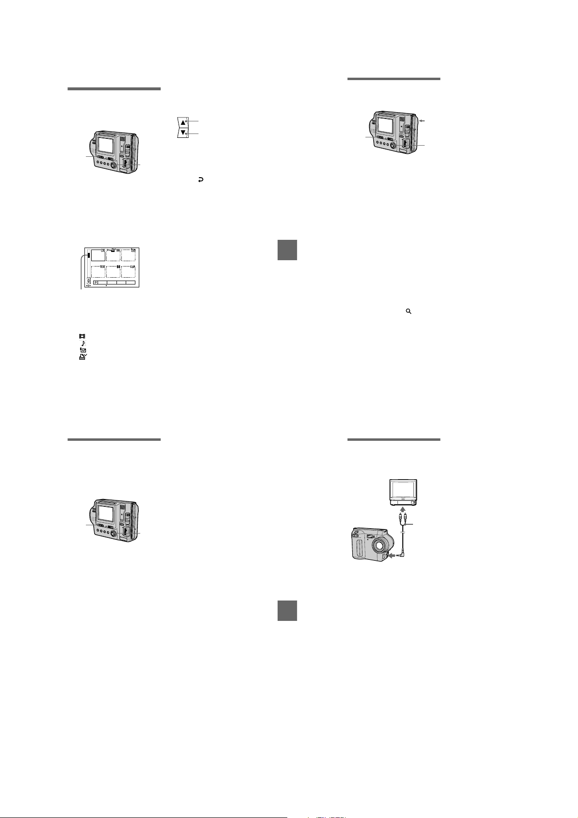
Various playback
.
B
Playing back six
images at once
(INDEX)
1
Set the PLAY/STILL/MOVIE
1
selector to PLAY.
Select [INDEX] on the LCD
2
screen.
Six images are display ed at once
(index screen).
Only the first frame of Clip Motion
filesisdisplayed.
2001 7 4 12:30PMMVC-001F
DELETE
FILE SETUPTOOL
SELECT SINGLE DISPLAY
This shows the position of the
currently displayed im ages relative
to all the recorded images.
The following marks are displayed
on each image according to the
image type and settings.
:Movingimagefile
:VOICEmodefile
:E-mailfile
:Printmark
-
:Protectmark
TEXT: TEXT file
TIFF: TIFF file
CLIP: Clip Motion file
(No mark): Normal recording (no
settings)
To display the next
(previous) index screen
Selectv/Vat the lower-left on the
LCD screen.
Displays the previous inde x
screen.
Displays the next index scre en
To return to normal playback
2
(single image)
• Select the desired image w ith the
control button.
• Select (Return) .
Note
When viewing a n image recorded in C lip
Motion or TEXT mode on the INDEX
screen, the imag em ay appear different from
the actual image.
BB
B Various playback
B
Enlarging a part of the
still image (Zoom and
trimming)
1
Set the PLAY/STILL/MOVIE
1
selector to PLAY.
Displaytheimagetobe
2
enlarged.
Zoom in/out the image with
3
the zoom lever.
The zoom scaling indic ator
appears on the LCD screen.
Press the control button
4
repeatedly to select the
desired portion of the image.
: The image moves downward
v
: The image moves upward
V
: The image moves rightward
b
: The image moves leftward
B
3
4
Notes
• Yo u cannot trim moving images, still
images recorded in Clip Motion, TEXT
mode, or uncompressed images.
• Zoomscalingisupto5× regardless of the
original image size.
• The quality of enlarged images may be
deteriorated.
• The original data is lefteven if you enlarge
the image.
• The enlarged image is recorded as the
newest file.
To return to the normal size
Zoom out with the zoom lever until the
zoom scaling indicator ( ×1.1)
59
disappears from the screen, or simply
press the center
To record an enlarged image
(trimming)
1
Enlarge the image.
2
Press the shutter button. The image
is recorded at 640×480 size and the
image on the LCD screen returns to the
normal size after r ecording.
60
.
z
Playing back the still
images in order
(SLIDE SHOW)
This function is useful for checking the
recorded images or for presentations,
etc.
1
2, 3
Set the PLAY/STILL/MOVIE
1
selector to PLAY.
Select [FILE] and then [SLIDE
2
SHOW] from the menu.
Set the following items.
INTERVAL
You can select from 1 min (one
minute),30sec(30seconds),
10 sec (10 second s), 5 sec
(5 seconds), or 3 s ec (3 seconds).
REPEAT
ON: Plays back images in a
continuous loop (W hen using the
floppy disk, the slide show stops
approximately 20 minutes*) until
[RETURN] is selected.
OFF: After all images have been
played back, the sl ide show ends.
∗ The slide show does not end until all
the images are played back, even if it
takes more than 20 minutes.
Select [START].
3
The slide show begins.
T o sk ip to th e ne x t/pre viou s
image during the slide show
Select\b/
LCD screen.
Note
The interval setting time may vary
depending on the image size.
at the lower-left on the
B\
Viewing images on a
TV screen
Before connecting y our camera, be
sure to turn off the TV.
Set the TV/VIDEO
switch to
“VIDEO”.
A/V
connecting
cable
to A/V OUT (MONO)
jack
Connect the A/V connecting
1
cable to the A/V OUT (MONO)
jack of your camera and to
the audio/video input jacks of
the TV.
BB
B Various playback
B
If your TV has stereo type input
jacks, connect the audio plug ofthe
A/V connecting cable to the Lch
jack.
Turn on the TV and start
2
playback on your camera.
The playback image appears onthe
TV screen.
Note
You cannot use a TV that has anantenna
(aerial) connector only.
To cancel the slide show
Select [CANCEL] in step 2 or 3.
61
62
1-15
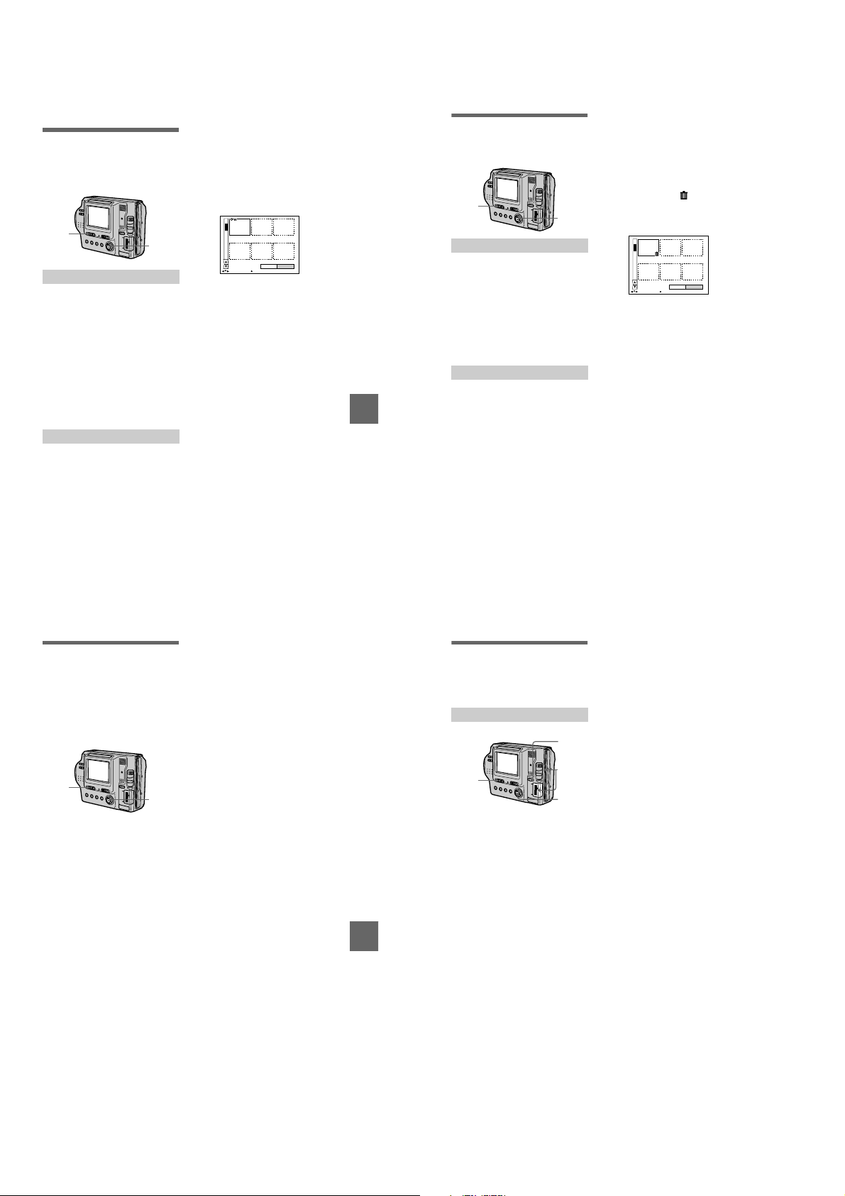
Editing
B
Preventing accidental
erasure (PROTECT)
The-(protect) indicator appears on
protected images.
1
2, 3
In single mode
Set the PLAY/STILL/MOVIE
1
selector to PLAY, then
display the image to be
protected.
Select [FILE], [PROTECT],
2
and then [ON] from the menu.
The displayed image is protected
-
indicator appears.
and the
To release protection
Select [OFF] in step 2.
In INDEX mode
Set the PLAY/STILL/MOVIE
1
selector to PLAY, then
display the INDEX screen.
Select [FILE], [PROTECT],
2
and then [ALL] or [SELECT]
from the menu.
When you select [ALL]
3
Select [ON].
All the images in the floppy disk or
“Memory Stick” are protected.
When you select [SELECT]
Select all the images to be
protected with the co ntrol button,
then select [ENTER]. The selected
images are pro tected.
0001-0006/0040
ENTERPROTECT CANCEL
SELECT OK
To release protection
If you selected [ALL] in step 2, select
[OFF]. If you selected [SELECT] in
step 2, select the images to be
unprotected with the control button,
then select [ENTER].
When you select [ALL]
Deleting images
(DELETE)
Protected images cannot be deleted.
1
2, 3
3
Select [ENTER].
All the unprotected images are
deleted.
When you select [SELECT]
Select all the images to be deleted
with the control button, then select
[ENTER]. The (delete)
indicator appears o n the selected
images and these images are
deleted.
In single mode
Set the PLAY/STILL/MOVIE
1
selector to PLAY, then
display the image to be
deleted.
Select [DELETE] and then
2
[OK] from the menu.
The image is deleted.
In INDEX mode
Set the PLAY/STILL/MOVIE
1
selector to PLAY, then
BB
B Editing
B
display the INDEX screen.
Select [DELETE] and then
2
[ALL]or[SELECT]fromthe
menu.
T o cancel deleting
Select [CANCEL] in step 2 or 3.
Note
If there are files on the “Memory Stick”
with names having the same la st 4 digits as
thefilenameoftheimagetobedeleted,
these files arealso deleted at the same time.
SELECT OK
0001-0006/0040
ENTERDELETE CANCEL
Changing the
recorded still image
size (RESIZE)
Use this function whe n you need a
small-size image to attach it to an Email. The original image is retained
even after resizing. The resized image
is recorded as the newest file.
1
2, 3
Set the PLAY/STILL/MOVIE
1
selector to PLAY, then
display the image of which
youwanttochangethesize.
Select [TOOL] and then
2
[RESIZE] from the menu.
Select the desired size .
3
• When the MS/FD selector is set
to FD
1472×1104, 1280×960,
1024×768, 640×480.
• When the MS/FD selector is set
to MS
1472 (FINE), 1280 (FINE),
1024 (FINE), 640 (FIN E).
The resized image is recorded,
then the display returns to the
image display before resizing.
Notes
• You c annot change the size of images
recorded in TEXT mode, moving images,
uncompressed images, or Clip Motion
images.
• When you change from a small size to a
large size, the pictur e quality deteriorates.
63
64
Select the media that the
Copying images
(COPY)
Copies images to another floppy disk
or “Memory Stick.”
In single mode
1
2
5
3, 4
Select the media using the
1
MS/FD selector.
Set the PLAY/STILL/MOVIE
2
selector to PLAY, then
display the image to be
copied.
Select [TOOL], and then
3
[COPY] from the menu.
BB
B Editing
B
4
image will be copied onto.
• When the MS/FD selector is set
to FD.
FD: Copies to the floppy
t
FD
disk
MS: Copies to the
t
FD
“Memory Stick”
• When the MS/FD selector is set
to MS.
MS
MS: Copies to the
t
“Memory Stick”
MS
FD: Copies to the floppy
t
disk
When you select [FD
t
FD], the camera
[MS
automatically starts copyi ng if the
floppy disk and “Memory Stick”
are inserted.
Insert or change the floppy
5
disk or “Memory Stick”
following the messages on
the LCD screen.
“RECORDING” appears. When
copying is completed,
“COMPLETE” appears.
To end copying, select [EXIT].
T o continue copying the
image to other floppy disks
or “ Memory Stick ”s
After “COMPLETE” appears instep 5,
select [CONTINUE] and repeat step 5
above.
t
MS] or
To cancel changing the size
Select [CANCEL] in step 3.
65
66
1-16
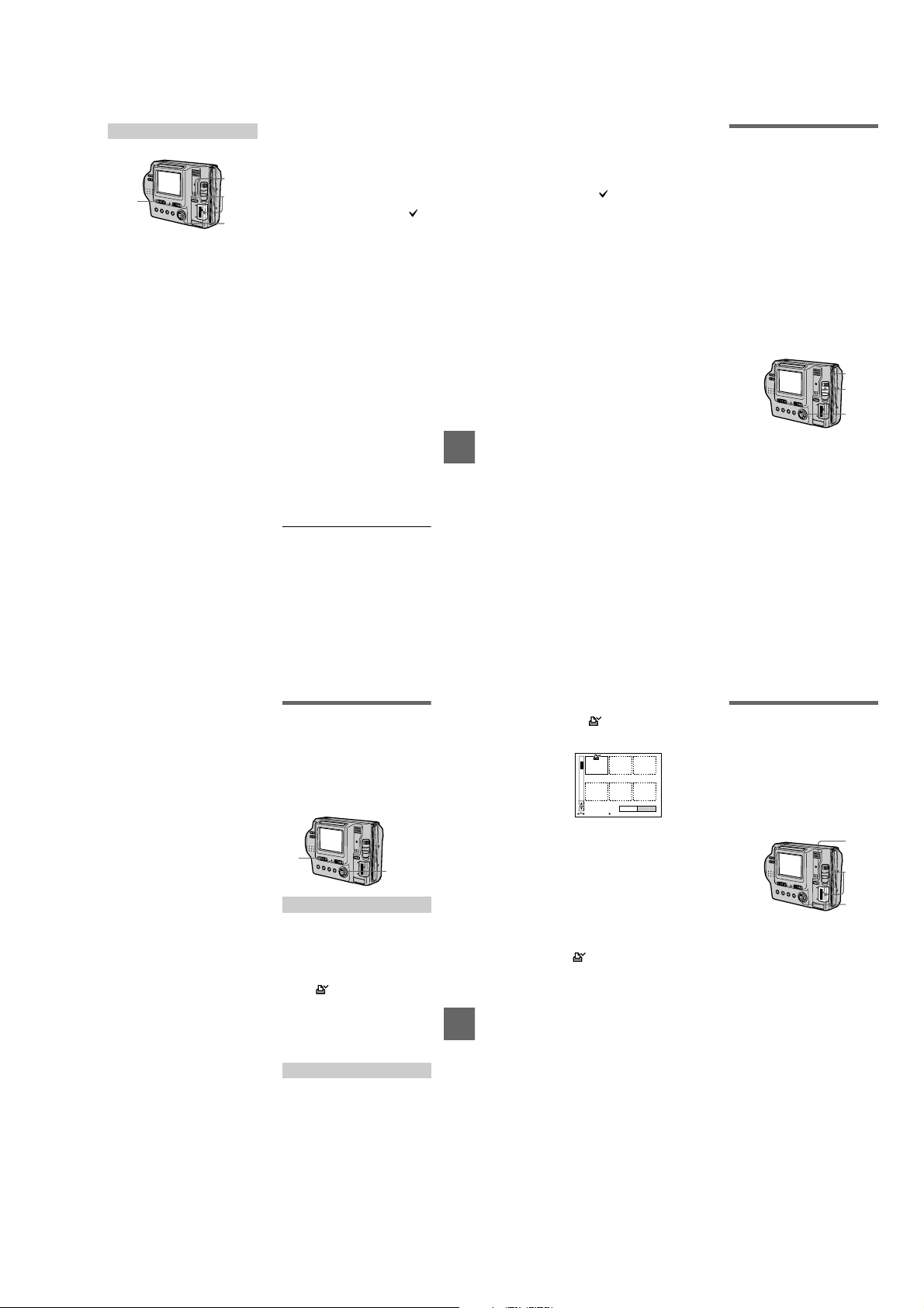
In INDEX mode
2
Select the media using the
1
MS/FD selector.
Set the PLAY/STILL/MOVIE
2
selector to PLAY, then
display the INDEX screen.
Select [TOOL], and then
3
[COPY] from the menu.
Select the media that the
4
image will be copied onto.
• When the MS/FD selector is set
to FD.
FD: Copies to the floppy
t
FD
disk
t MS: Copies to the
FD
“Memory Stick”
• When the MS/FD selector is set
to MS.
MS
MS: Copies to the
t
“Memory Stick”
MS
FD: Copies to the floppy
t
disk
1
6
3, 4, 5
When you select [ALL]*
5
Select [OK].
∗ [ALL] can be selected only when
selecting [FD
MS].
When you select [SELECT]**
Select all the images to be copied
with the control button. The
mark appears on th e selected
images and then select [ENTER].
∗∗When selecting [MS t FD], the
Insert or change the floppy
6
disk or “Memory Stick”
following the messages on
the LCD screen.
“RECORDING” appears. When
copying is completed,
“COMPLETE” appears.
To end copying, select [EXIT].
To continue copying the
image to other floppy disks
or “ Memory Stick ” s
After “COMPLETE” appears in step 6,
select [CONTINUE] and repe at step 6.
When selecting [MSt FD], if the
amount of total images that will be
copied is too large to co py to one
floppy disk, the images will be copied
using multiple floppy disks.
t FD] or [FD t
necessary number of floppy disks
appears after selecting [ENTER].
Select [OK] again.
To cancel copying partway
Select [CANCEL].
Notes
• You c annot copy uncompressed images.
• You c annot copy the image that is bigger
than 1.4 MB.
• You c annot copy the images that the total
amount of the images is bigger than
1.4 MB. If “NOT ENOUGH MEMORY”
appears or flashes on the INDEX
screen, cancel some images to copy and try
again.
• If you eject and insert the floppy disk or
“Memory Stick” without selecting [ EXIT]
after “COMPLETE” appears, the image
will be copied.
• The number of floppy disks that is needed
for copying is as a guide, which is
displayed when selecting [MS
t FD].
Copying all the
information on your
floppy disk (DISK
COPY)
You can copy to another disk not only
the images you have recorded with
your camera but also various files you
have created in other software with
your computer.
Notes
• Once you carry out DISK COPY, all
information saved on the recipient floppy
diskiserasedtobereplacedbynewly
written data including the p rotected image
data. Check the contents of the recipient
disk before copying the disk.
• Be sure to usethe floppy disk that has been
formatted by this camera to carryo ut
DISK COPY (page 70).
1, 4
3
2
Set the MS/FD selector to FD,
1
BB
B Editing
B
then insert the floppy disk to
be copied.
Select [FILE], [DISK TOOL],
2
[DISK COPY], and then [OK]
from the menu.
“DISK ACCESS” appears.
When “CHANGE FLOPPY
3
DISK” is displayed, eject the
floppy disk.
“INSERT FLOPPY DISK”
appears.
Insert another floppy disk.
4
“RECORDING” appears. When
copying is completed,
“COMPLETE” appears.
To end copying, select [EXIT].
To continue copying to other
floppy disks
After “COMPLETE” appears instep 4,
select [CONTINUE] andrepeat steps 3
and 4 above.
To cancel copying partway
Select [CANCEL].
Note
If you eject and insert the floppy disk
without selecting [EXIT] after
“COMPLETE” appears, D ISK COPY will
be carried out onto the floppy dis k.
67
Selecting st ill im a ges
to print (PRINT MA RK)
You can mark a print mark on still
images recorded wit h your camera.
This mark is convenient when you
have images printed at a shop that
conforms with the DPOF (Digital Print
Order Format) standard.
1
2, 3, 4
In single mode
Set the PLAY/STILL/MOVIE
1
selector to PLAY and display
theimageyouwanttoprint.
Select [FILE], [PRINT MARK],
2
and then [ON] from the menu.
The (print) mark is marked on
the displayed image.
To unm ark the print mark
Select [OFF] in step 2.
In INDEX mode
Set the PLAY/STILL/MOVIE
1
selector to PLAY, then
display the INDEX screen.
Select [FILE], [PRINT MARK],
2
and then [SELECT] from the
menu.
Selecttheimagestobe
3
marked with the control
button.
68
Select [ENTER].
4
The marks on the selected
images change from green to
white.
0001-0006/0100
ENTERPRINT MARK CANCEL
SELECT OK
To unm ark selected print
marks
Select the images to be unmarked in
step 3 with the control button, then
select [ENTER].
To unmark all the print
marks
Select [FILE], [PRINT MARK],
[ALL],andthen[OFF]fromthemenu.
The marks on all images are
removed .
To print out using the FVP-1
Mavic a Printe r
Set PRESET SELECT SW to PC on
the printer.
BB
B Editing
B
Notes
• You c annot mark moving images, Clip
Motion images or images r ecorded in
TEXT mode.
• If you mark an image recorded in TIFF
mode with a print mark, on ly the
uncompressed image is printed, a nd the
JPEG image recorded at the sa me time is
not printed.
Format
When you format a floppy disk or
“Memory Stick,” all data stored on the
floppy disk or “Memory Stick” will be
deleted. Check the contents of the
floppy disk or “Memory Stick” before
formatting.
Note
Even if images are protected, these images
will be deleted.
1
2
3
Selectthefloppydiskor
1
“Memory Stick” using the
MS/FD selector.
Insert only the floppy disk or
2
“Memory Stick” you want t o
format.
Be sure to in sert only th e media
youwanttoformat.
Select [FILE] from the menu.
3
• When formatting a floppy disk
Select [DISK TOOL],
[FORMAT], and then [OK] from
the menu.
• When formatting a “Memory
Stick”
Select [FORMAT], and then
[OK] from the menu.
T o cancel formatting
Select [CANCEL] in step 3.
69
70
1-17

Notes
• Format the floppy disk or “Memory
Stick” only using this camera. You
cannot format the floppy disk or
“Memory Stick” using a computer
via the USB c able.
• When you format, be sure to use a fully
charged battery p ack or the AC power
adaptor as the p ower source.
As an external drive
B
Using the camera as
an external drive of a
computer
Once you connect the camera to a
computer using the US B cable, you
can use the camera as a floppy disk/
“Memory Stick” drive of a computer.
Install the USB driver to the computer
beforehand (page 29).
For Windows 98, Windows
98SE, Windows Me, and
Windows 2000 Professional
Users
Connect the camera to the
1
computer using the supplied
USB cable.
Select the drive type using
2
the MS/FD selector on this
camera.
When used as the floppy disk
drive, set the MS/FD select or to
FD.
When used as the “Memory Stick”
drive, set the MS/FD select or to
MS.
Connect the AC power
3
adaptor and turn on the
camera.
Open “My Computer” on
4
Windows and check the icon
“Removable Disk,” then use
the camera as an external
drive.
Note
When using Windows Me orWindows 2000
Professional, see also page 3 2.
71
BB
B As an external drive
B
Additional information
Precautions
On cleaning
Cleaning the LCD screen
Wipe the screen su rface with a
cleaning cloth (not sup plied) or an
LCD cleaning kit (not supplied) to
remove fingerprints, dust, etc.
Cleaning the camera surface
Clean the camera surface with a soft
cloth slightly moistened with water,
then wipe the surface dry. Do not use
any type of solvent such as thinner,
alcohol or benzene as this may damage
the finish or the casing.
After using your camera at the
seashore or other dusty locations
Clean your camera c arefully.
Otherwise, the salty air may corrode
the metal fittings or dus t may enter the
inside of your camera, causing a
malfunction.
On floppy disks
To protect data recorded on floppy
disks, note the fol lowing:
• Avoid storing floppy disks near
magnets or magnetic fields such as
those of sp eakers and televisions.
Otherwise, permanent erasure of disk
data may result.
• Avoid storing floppy disks in are as
subject to direct su nlight or sources
of high temperature, such as a
heating device. Floppy disk warping
or damage may result, rendering the
disk useless.
• Avoid contact with the disk’ssurface
by opening the disk shutter plate. If
the disk’s surface become s
blemished, data may be rendered
unreadable.
72
• Avoid getting liquids on the floppy
disk.
• Be sure to use a floppy disk case to
ensure protection o f important data.
• Even when you u se a 3.5 inch 2HD
floppy disk, image data may not be
recorded and/or displa yed depending
on the using environment. In this
case, use a disk o f other brand.
On operating temperature
Your camera is designed for use
between the temperatures of 0°Cto
40°C(32°Fto104°F). Recording in
extremely cold or hot places that
exceed this range is not r ecommended.
On moisture condensation
If the camera is brought directly from a
cold to a warm location, or is placed in
a very damp room, moisture may
condense inside or out side the camera.
Should this occur, the camera will not
operate properly.
Moisture condensation occurs
easily when:
• The camera is brought from a cold
location such as a s ki slope into a
warmly heated room.
• The camera is t aken from an air-
conditioned room or car interior to
the hot outdoors, etc.
How to prevent moisture
condensation
When bringing the camera f rom a cold
place to a warm place, seal the camera
in a plastic bag and allow it to a dapt to
conditions at the new location over a
period of time (abo ut an hour).
If moisture condensation occurs
Immediately eject the floppy disk, then
turn off the camera and wait about an
hour for the moisture to evaporate.
Note that if you atte mpt to re cord with
moisture remaining inside the lens, you
will be unable to record clear images.
On AC power adaptor
• Unplug the unit from the wall outlet
(mains) when you are not using the
unit for a long time. To disconnect
the power cord (m ains lead), pull it
out by the plug. Never pull the power
cord (mains lead ) itself.
• Do not operate the unit with a
damaged cord (mains lead) or if the
unit has been dropped or damaged.
• Do not bend t he power cord (mains
lead) forcibly, or place a heavy object
on it. This will dama ge the cord
(mains lead) and may cause fire or
electrical sh ock.
• Prevent metallic objects from coming
into contact with the metal parts of
the connecting section . If this
happens, a short may occur and the
unit may be damaged.
• Always keep metal contacts clean.
• Do not disassemble the unit.
• Do not apply mechanical shock or
drop the unit.
• While t he unit is i n use, parti cularly
during charging, keep it away from
AM receivers and video equipm ent.
AM receivers and video equipm ent
disturb AM reception and video
operation.
• The unit b ecomes warm durin g use.
This is not a malfunction.
• Do not place the unit in locations that
are:
— Extrem ely hot or cold
— Dusty or dirty
— Very humid
— Vibrating
On battery pack
• Use only the spe cified charger with
the charging function.
• To prevent accident from a short
circuit, do not allow metal objects to
come into contact with the battery
terminals.
• Keep the battery pack away from
fire.
• Never expose the battery pa ck to
temperatures above 60°C (140°F),
such as in a car parked in the sun or
under direct sunlight.
• Keep the battery pack dry.
• Do not expose the battery pack to any
mechanical shock.
• Do not disassemble nor modify the
battery pack.
• Attachthebatterypacktothecamera
securely.
• Charging while some capacity
remains does not affect the origina l
battery capacity.
On the built-in rechargeable
lithium battery
Your camera is supplied with a built-in
rechargeable lithium battery installed
so as to retain the date and time, etc.,
regardless of the setting of the
POWER switch. The built-in
rechargeable lithium battery is always
charged as long as you are using your
camera. The battery, however, will get
discharged gradually if you do not use
your camera. It will be completely
discharged in about six months if you
do not use your camera at all. Even if
the built-in rechargeable lithium
battery is not charged, it will not affect
the camera operation. To retain the
date and time, etc., charge the battery if
the battery is discharged.
73
Additional information
Charging the built-in rechargeable
lithium battery:
• Connect your camera to house
current (mains) using the AC power
adaptor supplied with your camera,
and leave your camera with the
power turned off for more than 24
hours.
• Or install the fully charged battery
pack in your camera, and leave your
camera with the power turned off for
more than 24 hours.
If any problem occurs, unplug your
camera and contact your nearest Sony
dealer.
On “Memory Sticks”
“Memory Stick” is a new compact,
portable and versatile IC recording
medium with a data capacity that
exceeds a floppy disk. “Memory Stick”
is specially designed for exchanging
and sharing digital data among
“Memory Stick” compatible products.
Because it is removable, “Memory
Stick” canalsobeusedforexternal
data storage.
There are two types of “Memory
Sticks”: general “Memory Sticks” and
“MagicGate Memory Sticks” that are
equipped with the MagicGate*
copyright protection technology.
Youcanusebothtypesof“Memory
Stick” with your camera. However,
because your camera does not support
the MagicGate standards, data
recorded with your camera is not
subject to MagicGate copyright
protection.
∗ MagicGate is copyright protection
technology that uses encryption
technology.
74
Notes
• Do not remove the “Memory Stick” while
reading or writing data.
• Data may be damaged if:
—you remove the “Memory Stick” or turn
off your camera while reading or writing
data.
—you use the “Memory Stick” in a
location subject to the effects of static
electricity or noise.
• Do not attach any other material than the
supplied label on the labeling position.
• When you carry or store the “Memory
Stick,” put it in its supplied case.
• Do not touch the terminals of a “Memory
Stick” with your hand or a metal object.
• Do not strike, bend or drop the “Memory
Stick.”
• Do not disassemble or modify the
“Memory Stick.”
• Do not allow the “Memory Stick” to get
wet.
“Memory Stick”,,“MagicGate
Memory Stick” and are
trademarks of Sony Corporation.
“MagicGate” and are
trademarks of Sony Corporation.
Using your camera
abroad
Power sources
Youcan use your camera in any
country or area with the supplied
battery charger within 100 V to 240
VAC,50/60Hz.Use a commercially
availableAC plug adaptor [a],if
necessary, depending on the design of
the wall outlet (mains) [b].
AC-L10A/L10B/L 10C
1-18
Watching the playback picture on
TV
If you want to view the playback
picture on a TV,you need a TV having
a video input jack and a video
connecting cable.
The color system of the TV must be
the same as that of your digital still
camera. Check the following list:
NTSC system
Bahama Islands, Bolivia, Canada,
Central America, Chile, Columbia,
Ecuador, Jamaica, Japan, Korea,
Mexico, Peru, Surinam, Taiwan,the
Philippines, the U.S.A., Venezuela,etc.
PALsystem
Australia, Austria, Belgium, China,
Denmark, Finland, Germany,Great
Britain, Holland, Italy, Kuwait,
Malaysia, New Zealand, Norway,
Portugal,Singapore, Spain, Sweden,
Switzerland,Thailand, etc.
PAL-Msystem
Brazil
PAL-Nsystem
Argentina, Paraguay, Uruguay
SECAM system
Bulgaria, Czech Republic, France,
Guiana, Hungary, Iran, Iraq, Monaco,
Poland, Russia, Slovak Republic,
Ukraine, etc.
About “ InfoLITHIUM ”
battery pack
What is the “InfoLITHIUM” battery
pack?
The “InfoLITHIUM” batterypackisa
lithium-ion battery pack that has
functions for communicating
information related to operating
conditions between your camera and
the AC power adaptor.
The “InfoLITHIUM” battery pack
calculates the power consumption
according to the operating conditions
of your camera, and displays the
remaining battery time in minutes.
Charging the battery pack
• Be sure to charge the battery pack
before you start using your camera.
• We recommend charging the battery
pack in an ambient temperature of
between 10°Cto30°C(50°Fto86°F)
until the POWER ON/OFF (CHG)
lamp goes out, indicating that the
battery pack is fully charged. If you
charge the battery pack outside of
this temperature range, you may not
be able to efficiently charge the
battery pack.
• After charging is completed, either
disconnect the AC power adaptor
from the DC IN jack on your camera
or remove the battery pack.
Additional information
Effective use of the battery pack
• Battery perfor mance decreases in
low-temperature surroundings. So,
the time th at the battery pack can be
used is shorter in cold places. We
recommend the following to use the
battery pack longer:
— Putthebatterypackinapocket
closetoyourbodytowarmitup,
and insert it in your camera
immediately before you start
taking shots.
— Usethelargecapacitybattery
pack (NP-F550, o ptional).
• Frequently using the LCD panel or
frequently operatin g the zoom wears
out the battery pack faster. We
recommend using the large capacity
battery pack (NP-F550, optional).
• BecertaintoturnthePOWERswitch
to off when not taking shots or
playingbackonyourcamera.
• We recommend have spare batteries
handy for two or thre e times the
expected shooting time, and make a
trial shots before taking the actual
shots.
• Do not expose the battery pack to
water. The battery pack is not waterresistant.
Remaining battery time indicator
• If the power goes off although the
battery remaining indicator indicates
that the battery pack has enough
power to operate, charge the battery
pack fully again so that the indication
on the battery remaining indicator is
correct. Note, however, that the
correct battery i ndication som etimes
will not be restored if it is used in
high temperatures for a long time or
left in a fully charged state, or the
battery pack is freq uently used.
Regard the remaining battery time
indication as the approximate
shooting time.
E
mark indicating there is little
• The
remaining battery time sometimes
flashes depending on the operating
conditions or am bient temperatu re
and environment even if the
remaining battery time is 5 to 10
minutes.
How to store the battery pack
• Even if the battery pack is not used
for a long time, store it in a dry, cool
place after fully charging it once pe r
year and then using t he battery pack
up on your camera. T his is to
maintain th e battery p ack’s functions.
• Tousethebatterypackuponyour
camera, leave the POWER switch to
on in PLAY mode until the power
goes off without a floppy disk or a
“Memory Stick” inserted.
Battery life
• The battery life is limited. Battery
capacity decreases little by little as
you use it more and more, and as
time passes. When the battery
operating time is shortened
considerably, a probable cause is that
the battery pack has r eached the end
of its life. Please buy a new battery
pack.
• The battery life varies according to
how it is stored and op erating
conditions and environment for each
battery pack.
Troubleshooting
If you experience trouble with your camera, first check the following items. Should
your camera still not operate properly after you have made these checks, consult your
Sony dealer or local authorized Sony service facility. If code displays (C:
appear on the LCD screen, the self-diagnosis display function is working
(page 85).
Symptom Cause and/or Solution
Your camera does not
work.
Your camera cannot
record images.
The picture is out of focus. • Your camera is not in macro recording mode when
The resizing function does
not work.
• You are not using an “InfoLITHI UM” battery pack.
t
Use an “InfoLITHIUM” battery pack (page 9).
• The floppy disk is not inserted properly.
t
Eject the disk, and insert it again (page 16).
• The battery level is too low. (The indicator
appears.)
t
Charge the battery pack fully (page 10).
• The AC power adaptor is not connected securely.
t
Connect it securely to the DC IN jack and a wall
outlet (mains) (page 1 0, 13).
• The malfunction occurs inside the camera.
t
Turn off the power, and turn on after one
minute, then check that the camera works
properly.
• The PLAY/STILL/MOVIE selector is set to PLAY.
t
Set it to STILL or MOVIE (pages 18, 23).
• No floppy disk is inserted into y our camera.
t
Insert a floppy disk (page 16).
• The tab on the disk is set to the unrecordable
position.
t
Set it to the recording position (page 16).
• No “Memory Stick” is inserted into your camera.
t
Insert a “Memory Stick” (page 17).
• The write-protect switch on the “Memory Stick” is
set to LOCK.
t
Set it to the recording position.
you shoot a subject that i s about 3 to 25 cm
(1 3/16 to 9 7/8 inc hes) away from the lens .
t
Set the macro recordi ng mode (page 53).
t
Move the zoom lever to the W side.
• You cannot resize moving images, text images, Clip
Motion images, and uncompressed images.
ss
ss:ss
ss)
ssss
ssss
75
Additional information
76
Symptom Cause and/or Solution
You cannot display a print
mark.
The picture is noisy. • Your camera is placed near a TV or other
The picture is too dark. • You are shooting a subject with a light source
The flash does not work. • The flash is set to .
The date and time are
recorded incorr ectly.
Vertical streaks appear
when you are shooting a
very bright subject.
The zoom does not work. • PROGRAM AE is set to the Panfocus mode.
Digital zoom does not
function.
The image is in
monochrome.
The image cannot be
played back on a
computer.
• You cannot display print marks on moving images,
text images and Clip Motion images.
equipment that uses st rong magnets.
t
Move your camera away from the TV, etc.
behind the subject.
t
Adjust the exposure (page 56).
• The brightness of the LCD screen is too low.
t
Adjust the brightness of the LCD screen
(page 20).
t
Set the flash to (no indication), , or
(page 22).
• ThecameraisinoneofthefollowingPROGRAM
AE modes: Twilight, Twilight plus, or Landscape.
t
Cancel the PROGRAM AE function or set the
flash to (page 22, 54).
• The PLAY/STILL/MOVIE selector is set to
MOVIE.
t
Set it to STILL.
• The date and time are not set correctly.
t
Set the correct d ate and time (page 14).
• This is called the smear phenomenon.
t
This is not a malfunction.
t
Cancel the Panfocus m ode (page 54).
• You cannot use digital zoom when recording
moving pictures.
• Digital zoom is set to [OFF].
t
Set digital zoom to [ON] at the menu.
• You shot the image in TEXT mode.
t
Cancel the TEXT mode (page 51).
• The picture effect is set to B&W.
t
Cancel the B&W mode (page 58).
t
Consult the computer or software manufacturer.
77
78
1-19
Symptom Cause and/or Solution
The image and sound
break off when you play
back an image on a
computer.
Yourc amera cannot delete
an image.
The power turns off
suddenly.
The image does not
appear on the TV screen.
The slide show function
stops automatically.
You cannot use the
PROGRAM AE function.
The macro function does
not work.
• You are playing back the file from the floppy disk
or “Memory Stick.”
t
Copy the file to the hard disk of the computer
andthenplaybackthefilefromtheharddisk
(page 32).
• The image is protected.
t
Cancel the protection (p age 63).
• With the PLAY/STILL/MOVIE selector set to
STILL or MOVIE, if you do not operate the camera
for about three minutes while the power is on, the
camera turns off automatically to prevent wearing
down the battery pack.
t
Turn on the camera.
• The battery pack is discharged.
t
Replace it with a fully charged battery pack.
• The VIDEO OUT setting of your camera is
incorrect.
t
Change the setting (page 45).
• The slide show fu nction stops after about
20 minutes when usi ng a floppy disk.
t
To continue the slide show, select [START]
again (page 61).
• The camera is se t to TEXT mode.
t
Cancel the TEXT mode (p age 51).
• PROGRAM AE is set to the Panfocus mode.
t
Cancel the Panfocus mode (page 54).
Additional information
Symptom Cause and/or Solution
Your computer does not
recognize your c amera.
Reinstall the USB driver when using Windows 98, Windows
98SE, Windows Me and Windows 2000 Professional
Turn on your computer and allow Windows to load.
1
Connect the USB jack on the camera and the computer with the
2
supplied USB cable.
Insert a media and set the MS/FD selec tor to the appropriate
3
position according to the media inser ted.
Connect the AC power adaptor to your camera and then to a w all
4
outlet (mains), and turn on the power of your camera.
• The battery level is low.
t
Use the AC power adaptor (page 13).
• The camera is turned off.
t
Turn on the camera.
• The USB cable is not connected firmly.
t
Disconnect the US B cable, and connect it again
firmly. Make sure that “USB MODE” is
displayed on the LCD screen (page 29).
• The USB connectors on your computer are
connected to other equipment besides the keyboard,
the mouse, and your c amera.
t
Disconnect the US B cables except for the ones
connected to the keyboard, the m ouse, and your
camera.
• The position of the MS/FD selector is not set to the
proper position for the media being used.
t
Set the MS/FD selector to the proper position.
• The USB driver is not installed.
t
Install the USB dr iver (page 29).
• For Windows 98, Windows 98SE, Windows
Me and Windows 2000 Professional users
Since the camera is connected to a computer with
the USB cable before installing the USB driver, the
drive is not recognized properly by the computer.
t
Delete the drive which is not recognized
properly, theninstall the USB driver. For details,
see the procedure be low.
Open “Device Manager” on Windows.
5
For Windows 98, Windows 98SE and Windows Me users:
Open [Control Panel] from [ My Computer], the n double-click [Sy stem].
1
System propert ies is displayed. Click th e [Device Manager] tab loc ated at the
2
top.
Click [ SonyDSC] in [ Other devices], then click the [Delete (E)]
3
button loccated at the lower-right corner.
For Windows 2000 Professional users:
* Log in with the permission of administrater.
Open [Control Panel] from [ My Computer], then double-click [Syste m].
1
System properties is displayed. Click the [Hardware] tab located at the top,
2
then click the [Device Manager (D)] button.
Click [View] in [Device Manager], then click [Devices by type (E)].
3
Right-click [ SonyDSC] in [ Other devices], then click [Delete (E)].
4
After the message appea rs to verify that you delete the device
6
manager, click the [OK] button.
Turn off the camera, disconnect the USB cable, and restart the
7
computer.
Install the USB driver in the supplied CD-ROM to the computer
8
following the procedure on page 29. Perform all steps without
skipping.
Battery packs
Symptom Cause and/or Solution
The battery pack cannot
be charged.
The battery life is short. • You are recording/playing back images under
• The power of the camera is turned on.
t
Turn off the power of the came ra (page 10).
extremely cold tem peratures.
• The battery pa ck is not charged enough .
t
Charge the battery pack fully.
• The battery pack is dead.
t
Replace the battery pack with a new one.
79
80
Symptom Cause and/or Solution
The indication of the
battery remaining time is
not proper, or the power is
immediately turned off
even if the battery
remaining indicator
indicates that the batter y
level is sufficient.
The POWER ON/OFF
(CHG) lamp flashes when
charging a battery pack.
The POWER ON/OFF
(CHG) lamp does notlight
up when charging a
battery pack.
Additional information
• You are using the camera for ma ny hours under
extremely hot or cold te mperatures.
• The battery pack is dead.
t
Replace the battery pa ck with a new one
(page 9).
• The battery level is too low.
t
Install the fully charged battery pack (page 9,
10).
• A deviation has occurred in the remaining battery
time.
t
Charge the battery pack fully (pag e 10).
• A malfunctio n has occurred in the battery pack.
t
Contact your Sony dealer or local authorized
Sony service facility.
• The AC power adaptor is not connected.
t
Connect the power cord firmly to a wall outlet
(page 10).
• The battery pack is not installed properly.
t
Install it properl y (page 9).
• Charging of the battery pack is complete.
81
82
1-20
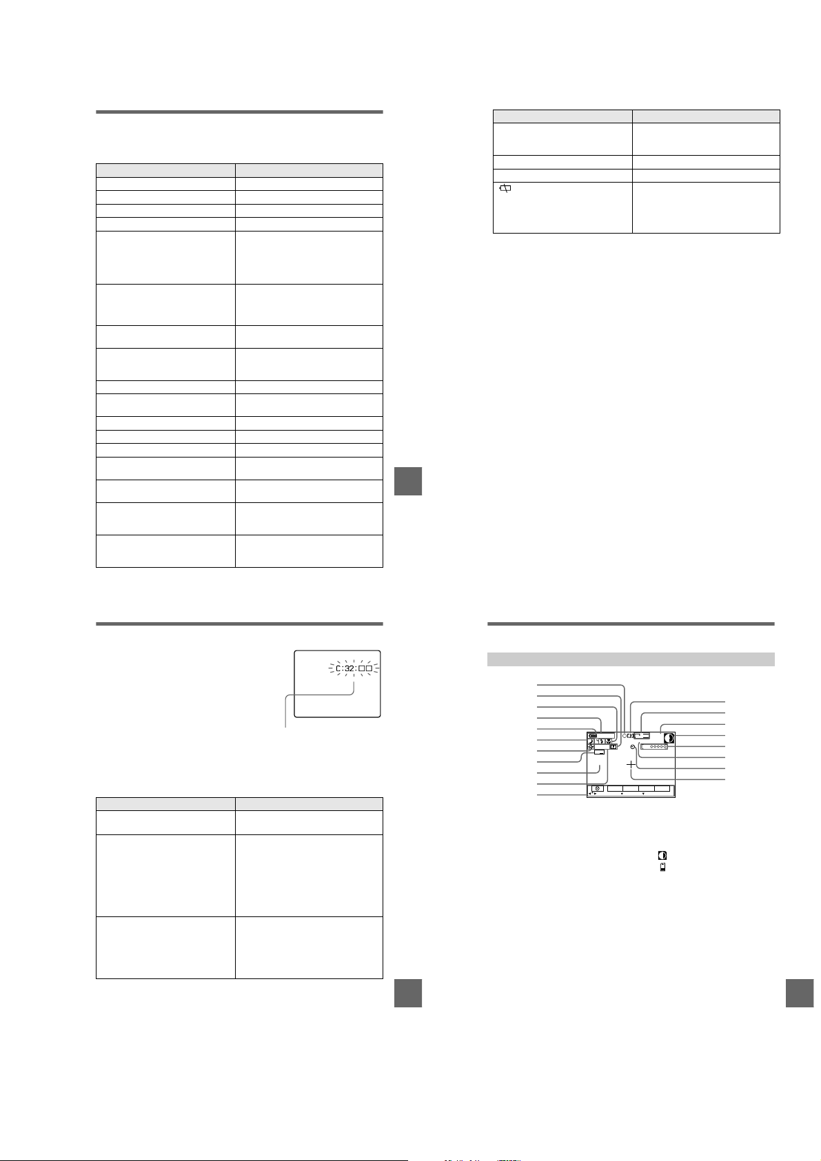
Warning and notice messages
Various messages appear on the LCD screen. Check the corresponding descriptions
in the following list.
Message Meaning
DRIVEERROR Thereistroublewiththediskdrive.
SYSTEM ERROR Turn the power off and on again.
NO DISK No disk is inserted.
NO MEMORY STICK No “Memory Stick” is inserted.
FORMAT ERROR • The floppy disk loaded is not MS-DOS
MEMORY STICK ERROR The inserted “Memory Stick” cannot be
DISKPROTECT Thetabonthediskissettothe
MEMORY STICK LOCKED The write-protect switch on the
formatted (512 bytes
• Failed to format the “Memory Stick.”
• The Floppy Disk Adaptor for M emory
Stick is inserted.
used with your camer a, or the “Memory
Stick” is damaged or not inserted
correctly.
unrecordable p osition.
“Memory Stick” is set to the LOCK
position.
DISK FULL The disk is full.
NO MEMORY SPACE The capacity of the “Memory Stick” is
not sufficient to record image s.
NO FILE No image is recorded on the disk.
FILE ERROR Trouble has occurred during pl ayback.
FILE PROTECT The image is protected.
DISK ERROR A 2DD floppy disk is inserted, or there is
DIRECTORY ERROR A directory with the same name already
NOT ENOUGH MEMORY The remaining capacity of the floppy
IMAGE SIZE OVER You tried to play back images with an
trouble with the disk.
exists.
disk or “Memory Stick” is not enough to
copy the image.
image size larger than the maximum
playback size of this c amera.
×
18 sectors).
83
Additional information
Message Me aning
INVALID OPERATION You are playing back a file that was
for “InfoLITHIUM” battery only
-
created on equipment other than your
camera.
The battery is not the “InfoLITHIUM” type.
The image is protected.
The battery level is too low. When the
remaining time is about 5 to 10 minutes,
E
may flash depending on the battery
pack used, operating conditions, or the
environment.
84
Self-diagnosis display
Your camera has a self-diagnosis display. This
function displays the c amera condition on the
LCD screen with a com bination of a letter and
four digits of numbers. If this appears, check the
following code chart. The code informs you of the
camera’s current condition. The last two digits
(indicated by
state of the camera.
Code Cause and/or Corrective Action
C:32:
C:13:
E:61:
E:91:
If you are unable to rectify the problem even if you try corrective actions a
few times when C:
authorized Sony service facility.
) will differ depending on the
ss
ss
ss
ss
ss
ss:ss
Self-diagnosis display
• C:ss:
ss
You can repair the camera
yourself.
• E:
ss:ss
Contact your Sony dealer or local
authorized Sony servic e facility.
• There is trouble with the disk drive.
t
Turn the power off and on again.
• An unform atted floppy disk or
“Memory Stick” is inserted.
t
Format the floppy disk or “Memory
Stick.” (page 70)
• A floppy dis k or “Memory Stick” not
compatible with this camera is inserted.
t
Change the floppy disk or “Memory
Stick.” (pages 16, 17)
• A camera malfunction that y ou cannot
repair has occurred.
t
Contact your Sony deal er or local
authorized Sony service facility and
inform them of the 5-digit
indication. (example: E:61:10)
is indicated, contact your Sony dealer or local
Additional information
LCD screen indicators
The indicators during recording
1
2
3
4
5
6
7
8
9
0
qa
AE lock indicator/Focus lock
A
indicator
Sharpness indicator
B
Focus mode indicator/Macro
C
indicator
Battery remaining indicator
D
Flash level indicator/Flash
E
mode indicator
PROGRAM AE indicator/Zoom
F
indicator
White balance indicator
G
DATE indicator
H
Picture effect indicator
I
EV level indicator
J
Menu bar and guide menu
K
They appear by pressing
control button and disappear by
.
V
pressing
Recording mo de/Clip Mo tion
L
indicator
Image size indicator
M
+1.0EV
DATE
SOLARIZE
on the
v
120min
SELECT
3:2
1280
REC 0:03
15s
EFFECT FILE SETU P
CAMERA
OK
MENU BAR OFF
Number of recorded images
N
Remaining disk capacity/
O
Remaining memory capacity
indicator
Recording time indicator
P
Self-diagnosis function
Q
indicator/Recording time
indicator
Self-timer indicator
R
Spot light-metering indicator
S
10
: Floppy disk
: “Memory Stick”
qs
qd
qf
qg
qh
qj
qk
ql
Additional information
85
87
1-21
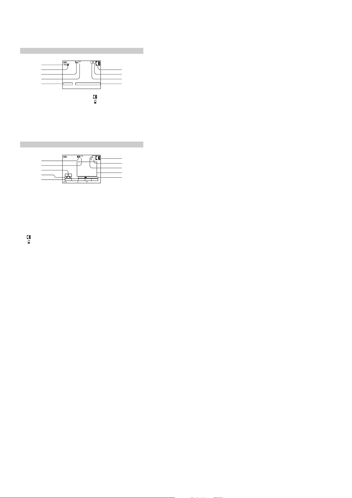
The indicators during still image playback
1
2
3
4
5
Protect indicator/Zoom scaling
A
indicator
Print mark indicator
B
Recording mode/Clip Motion
C
indicator
Image size indicator
D
File name*
E
Remaining disk capacity/Remaining
F
memory capacity indicator
120min
MVC-011F
11/12
1280
12:00AM2001 7 4
Number of stored images on a
G
floppy disk or “Memory Stick”
Image number
H
Recording date of the playback
I
image*
∗ When the menu bar is dis played, this
indicator disappears from th e screen.
The indicators during moving image playback
1
2
3
4
5
Moving image file indicator
A
Image size indicator
B
Playback button/pause button
C
is displayed during s top, and
B
during playback.
Image searching buttons
D
Menu bar and guide menu
E
Remaining disk capacity/Remaining
F
memory capacity indicator
120min
DELETE
INDEX FILE SETUPTOOL
SELECT OK
X
6/8
160
0:10
MENU BAR OFF
Counter
G
Image number/number of
H
stored images on a floppy disk
or “Memory Stick”
Playback im age
I
Playback ba r
J
: Floppy disk
: “Memory Stick”
88
: Floppy disk
: “Memory Stick”
6
7
8
9
6
7
8
9
0
1-221-22 E
 Loading...