

SONY MVC-FD85, FD90 Service Manual
MVC-FD85/FD90
SERVICE MANUAL
Level 1
Ver 1.0 2000. 03
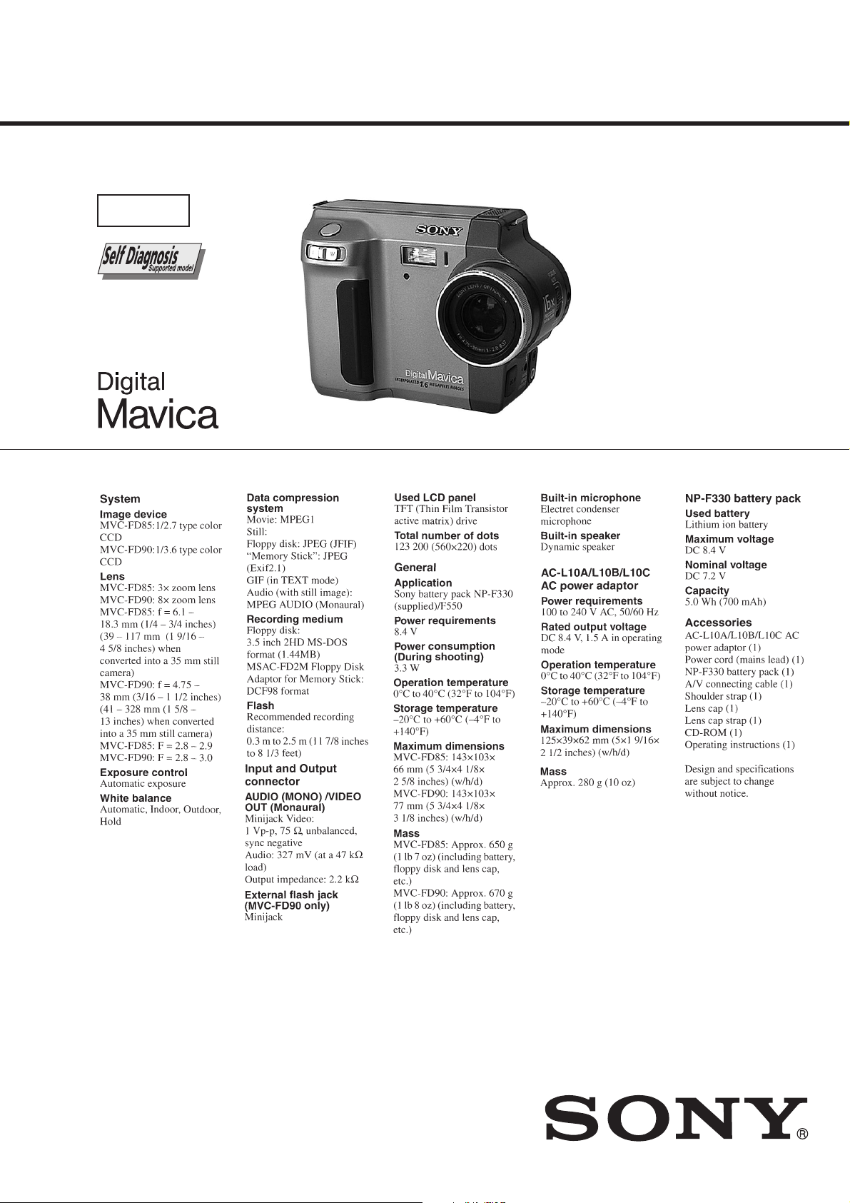
Photo: MVC-FD90
SPECIFICA TIONS
AEP Model
UK Model
DIGITAL STILL CAMERA

TABLE OF CONTENTS
SERVICE NOTE ····································································· 3
1. MAIN PARTS
1. ORNAMENTAL PARTS ···················································· 5
2. DISASSEMBLY ································································· 6
2-1. CABINET (REAR) BLOCK ASSEMBLY ························ 6
2-2. FC-72 BOARD, FLOPPY DISK DRIVE ·························· 7
2-3. LENS BLOCK ASSEMBLY··············································8
2-4. FLASH UNIT, FU-140/146 BOARD································· 8
2-5. DC-IN CONNECTOR, MICROPHONE UNIT················· 9
2-6. HINGE ASSEMBL Y,
BATTERY TERMIN AL BOARD······································ 9
2-7. LCD, PK-50/52 BOARD·················································· 10
2-8. EJECT BUTTON SECTION ··········································· 11
2. REPAIR PARTS LIST
2-1. EXPLODED VIEWS ······················································· 12
2-1-1.CABINET (FRONT) BLOCK SECTION-1 ···················· 12
2-1-2.CABINET (FRONT) BLOCK SECTION-2 ···················· 13
2-1-3.CABINET (REAR) BLOCK SECTION ·························· 14
2-1-4.LENS BLOCK SECTION················································ 15
Table for differences of function
Model
CCD imager size
Lens Optical
Manual foucs
LANC jack
CD board
FC board
PD board
FU board
MVC-FD85
1/2.7 inch
3 ×
CD-248
FC-72
PD-52
FU-146
MVC-FD90
1/3.6 inch
8 ×
a
a
CD-246
FC-72
PD-50
FU-140
3. GENERAL
Getting started
Identifying the parts ································································ 16
Preparing the power supply ···················································· 17
Setting the date and time························································· 18
Inserting a floppy disk ···························································· 18
Basic operations
Recording still images ···························································· 18
Recording moving images ······················································ 19
Playing back still images ························································ 20
Playing back moving images ·················································· 20
Viewing images using a personal computer ··························· 20
Image file storage destinations and image file names ············ 21
Advanced operations
Before performing advanced operations································· 21
Additional information
Precautions·············································································· 28
Using your camera abroad ······················································ 28
Troubleshooting ······································································ 28
Warning and notice messages ················································· 29
Self-diagnosis display ····························································· 29
LCD screen indicators ···························································· 30
Remark
a: with CN401 of FC-72 board.
a: with J782 of PK-50 board.
SAFETY-RELATED COMPONENT WARNING!!
COMPONENTS IDENTIFIED BY MARK 0 OR DOTTED LINE WITH
MARK 0 ON THE SCHEMATIC DIAGRAMS AND IN THE PARTS
LIST ARE CRITICAL TO SAFE OPERATION. REPLACE THESE
COMPONENTS WITH SONY PARTS WHOSE PART NUMBERS
APPEAR AS SHOWN IN THIS MANUAL OR IN SUPPLEMENTS
PUBLISHED BY SONY.
SAFETY CHECK-OUT
After correcting the original service problem, perform the following
safety checks before releasing the set to the customer.
1. Check the area of your repair for unsoldered or poorly-soldered
connections. Check the entire board surface for solder splashes
and bridges.
2. Check the interboard wiring to ensure that no wires are
"pinched" or contact high-wattage resistors.
3. Look for unauthorized replacement parts, particularly
transistors, that were installed during a previous repair . Point
them out to the customer and recommend their replacement.
4. Look for parts which, through functioning, show obvious signs
of deterioration. Point them out to the customer and
recommend their replacement.
5. Check the B+ voltage to see it is at the values specified.
6. Flexible Circuit Board Repairing
• Keep the temperature of the soldering iron around 270˚C
during repairing.
• Do not touch the soldering iron on the same conductor of the
circuit board (within 3 times).
• Be careful not to apply force on the conductor when soldering
or unsoldering.
— 2 —

• NOT FOR REPAIR
Capacitor
Short jig
SERVICE NOTE
Make sure that the flat cable and flexible board are not cracked of
bent at the terminal.
Do not insert the cable insufficiently nor crookedly.
Cut and remove the part of gilt
which comes off at the point.
(Take care that there are
some pieces of gilt left inside)
When remove a connector, don't pull at wire of connector.
Be in danger of the snapping of a wire.
When installing a connector, don't press down at wire of connector.
Be in danger of the snapping of a wire.
[Discharging of the FLASH unit’s charging capacitor]
The charging capacitor of the FLASH unit is charged up to the
maximum 300 V potential.
There is a danger of electric shock by this high voltage when the
capacitor is handled by hand. The electric shock is caused by the
charged voltage which is kept without discharging when the main
power of the MVC-FD85/FD90 is simply turned off. Therefore,
the remaining voltage must be discharged as described below.
Preparing the Short Jig
To preparing the short jig. a small clip is attached to each end of a
resistor of 1 kΩ /1 W (1-215-869-11)
Wrap insulating tape fully around the leads of the resistor to prevent
electrical shock.
1 kΩ/1 W
Wrap insulating tape.
Discharging the Capacitor
Short circuits between the positive and the negative terminals of
charged capacitor with the short jig about 10 seconds.
— 3 —
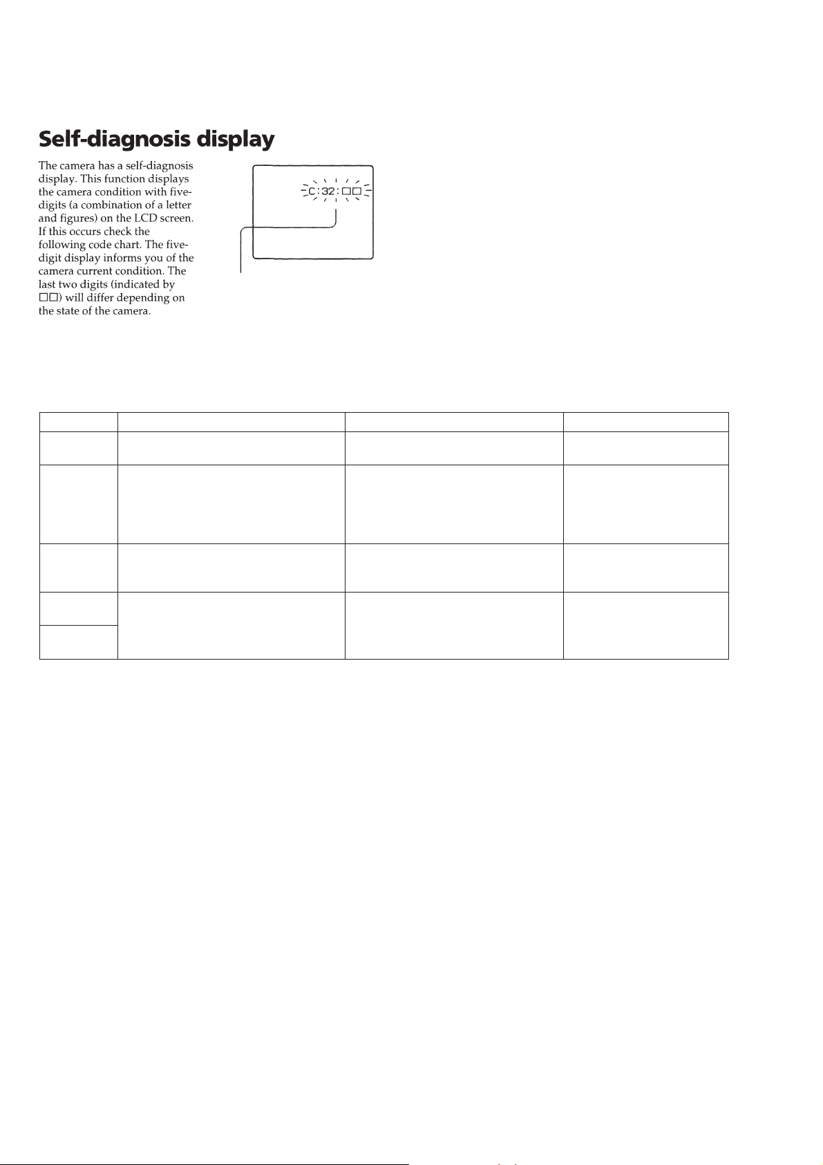
[Description on Self-diagnosis Display]
Self-diagnosis display
• C: ss: ss
The contents which can be handled
by customer, are displayed.
• E: ss: ss
The contents which can be handled
by engineer, are displayed.
Note : The “Self-diagnosis” data is backed up by the coin lithium
battery.The data will be lost and initialized when the coin lithium
battery is removed.
Display Code
C:32:01
C:13:01
E:91:01
E:61:00
E:61:10
Countermeasure
Change the disk and turn off the main
power then back on.
Replace the floppy disk.
Format the floppy disk with the MVCFD85/FD90.
Checking of flash unit or replacement of
flash unit
Checking of lens drive circuit
Cause
Defective floppy disk.
• The type of floppy disk that cannot be
used by this machine, is inserted.
(Such as 2DD)
• Data is damaged.
• Unformatted disk is inserted.
Abnormality when flash is being
charged.
When failed in the focus initialization.
Caution Display During Error
DRIVE ERROR
DISK ERROR
Flash LED
Flash display
Flashing at 3.2 Hz
—
— 4 —
1. MAIN PARTS
)
Note:
• Follow the disassembly procedure in the numerical order given.
• Items marked “*” are not stocked since they are seldom required for routine service. Some delay should
be anticipated when ordering these items.
• The parts numbers of such as a cabinet are also appeared in this section.
Refer to the parts number mentioned below the name of parts to order.
1. ORNAMENTAL PARTS
CPC Lid
3-058-792-01
Note : The components identified by mark 0 or dotted
line with mark 0 are critical for safety.
Replace only with part number specified.
MVC-FD85/FD90
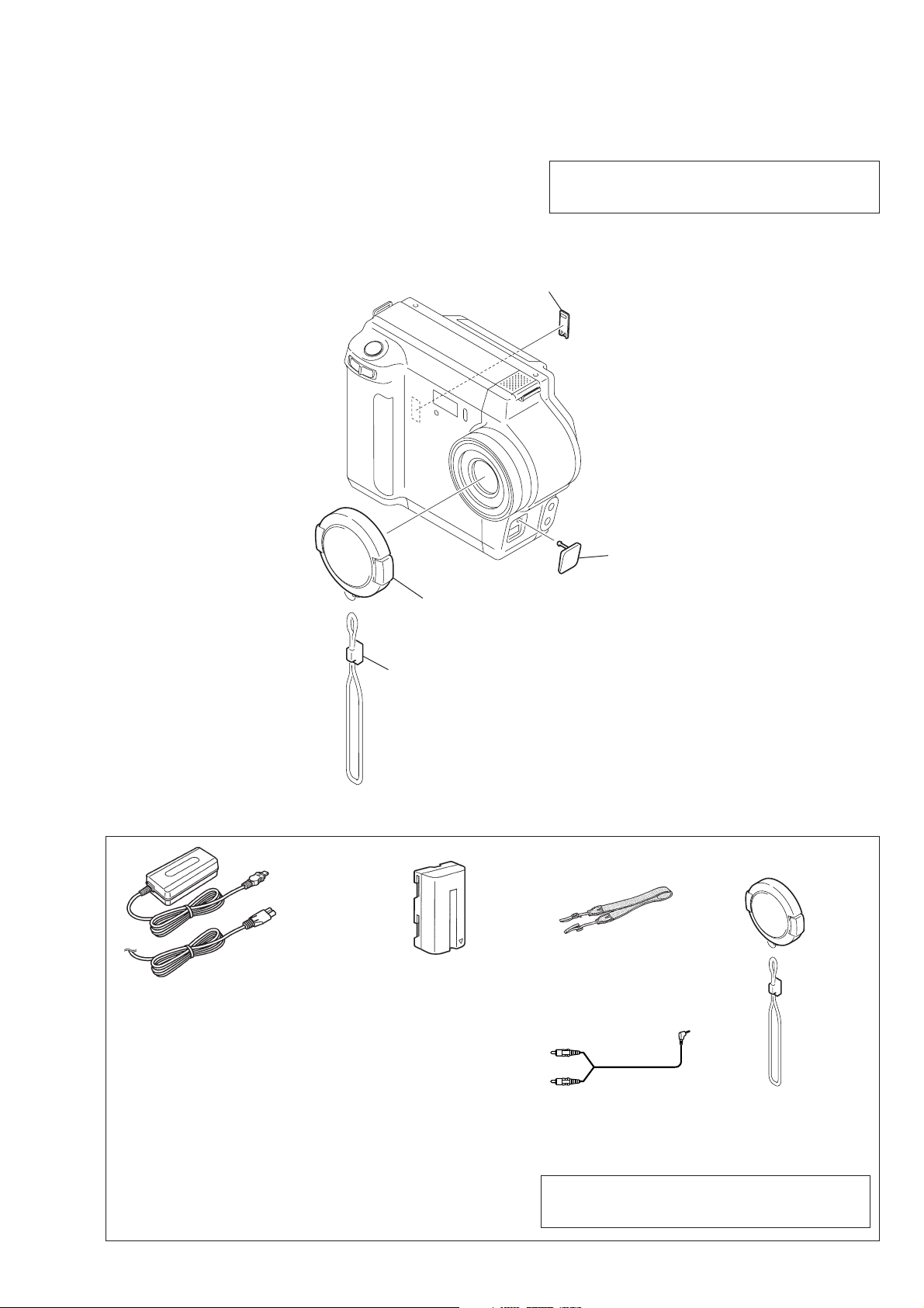
Checking supplied accessories
AC-VF10 power adaptor (1)
0
1-475-599-11
Power cord set (1) (AEP model)
0
1-769-608-11
Power cord (with filter) (1) (UK model)
0
1-783-374-11
Lens cap assembly
X-3950-660-1
Cap string
3-724-594-01
NP-F330 battery pack (1)
(MVC-FD90: AEP, UK model)
A-7094-141-A
DC cover
3-058-767-01
Shoulder belt (S) (1)
3-987-015-01
(Fig. A
(Fig. B)
Other accessories
3-060-831-11 MANUAL, INSTRUCTION (ENGLISH)(AEP,UK MODEL)
3-060-831-21 MANUAL, INSTRUCTION (FRENCH/GERMAN)(AEP MODEL)
3-060-831-31 MANUAL, INSTRUCTION (SPANISH/PORTUGUESE)(AEP MODEL)
3-060-831-41 MANUAL, INSTRUCTION (ITALIAN/DUTCH)(AEP MODEL)
3-060-831-61 MANUAL, INSTRUCTION (SWEDISH/RUSSIAN)(AEP MODEL)
— 5 —
Cord connector (A/V) (1)
1-783-738-11
Note : The components identified by mark 0 or dotted
line with mark 0 are critical for safety.
Replace only with part number specified.
(Fig. A) Lens cap assy (1)
X-3950-660-1
(Fig. B) Cap string (1)
3-724-594-01

2. DISASSEMBLY
The following flow chart shows the disassembly procedure.
2-1 . Cabinet (Rear) block assembly
2-7. LCD, PK-50/52 board, Speaker
2-8. Eject button section
2-2. FC-72 board, Floppy disk drive
MVC-FD85/FD90
2-3. Lens block assembly
2-4. Flash unit, FU-146 board
2-5. DC-IN connector, Microphone UNIT,
Control switch block (MF 330)(MVC-FD90)
2-6. Hinge assembly, Battery terminal board,
Control switch block
NOTE: F ollo w the disassembly procedure in the numerical order given.
2-1. CABINET (REAR) BLOCK ASSEMBLY
7
Cabinet (front) block assembly
5
Two screws (M2 × 4),
lock ace, p2
3
Two screws (M2 × 4), lock ace, p2
FC-72
Board
a
4
Screw (M2 × 4),
lock ace, p2
a
2
Screw (M2 × 4),
lock ace, p2
6
Cabinet (rear) block assembly
1
Two screws (M2 × 4),
lock ace, p2
— 6 —
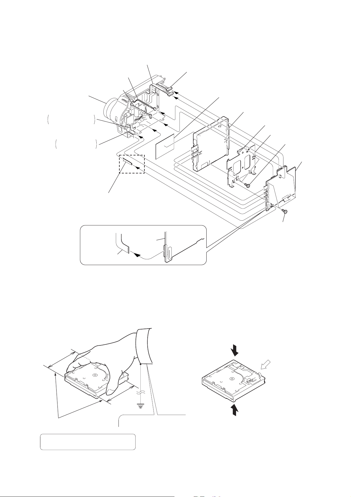
2-2. FC-72 BOARD, FLOPPY DISK DRIVE
9
FU-51 harness (12p)
1
Microphone unit (2p)
q;
qa
Cabinet (front)
block assembly
2
Flexible board (18P)
MVC-FD85 FP-231
MVC-FD90 FP-167
3
Lens block assembly
MVC-FD85 (26P)
MVC-FD90 (24P)
Flash unit (10p)
4
Control switch block(MF330)(6p)
(MVC-FD90)
8
FU-52 harness (9p)
qf
Blind sheet
qg
Floppy disk drive (4 × )
6
Claw
qd
FC Bracket
FC-72
Board
qs
Three screws
(M2 × 2.5)
7
FC-72 board
MVC-FD90
Lens block
assembly (26P)
Cautions When Handling FDD
1. Correct Way of Holding an FDD
FC-72
board
5
Four screws (M2 × 2.5)
2. Prohibited Items
Do not apply any physical stress to the center of the top plate.
Do not apply any physical
stress to the spindle motor.
Range of holding FDD
If the FDD is not held correctly,
the components of the FDD may be bent.
Wear an earthed wrist strap.
Do not hold an FDD by sandwiching
the upper and lower surfaces.
— 7 —
2-3. LENS BLOCK ASSEMBLY
2
Lens block assembly
(MVC-FD90)
3
Cabinet (front) assembly
1
Tapping screw (M2 × 5)
2
Lens block assembly
(MVC-FD85)
REMOVING THE FOCUS STEPPING
MOTOR, ZOOM STEPPING MOTOR
1
Two screws (M2 × 5)
2
Lens frame
4
screw
5
T wo screws
7
6
Remove
soldering
Zoom stepping motor
9
Remove soldering
q;
Focus stepping motor
8
Two screws
3
Lens sheet
1
Two screws
(M2
5
Remove soldering
6
Focus
motor unit
4
Two screws
REMOVING THE FOCUS MOTOR
UNIT, ZOOM MOTOR UNIT
3
Lens sheet (L)
×
5)
2
Lens frame
8
Remove soldering
9
Zoom
motor unit
7
Two screws
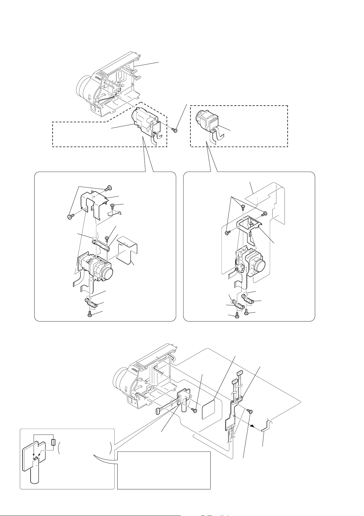
2-4. FLASH UNIT, FU-140/146 BOARD
Short jig (see page 3)
1k
Ω
. 1W
parts.No.1-215-869-11
When handling the flash unit, be sure to
discharge the chargingcapacitor before
handling it.
For discharge short jig to the positive (+)
and negetive (–) terminals of the charging
capacitor for about ten seconds.
3
Flash unit
— 8 —
2
T wo tapping
screws (M2
1
ST inslating sheet
6
FU-140 board (MVC-FD90)
×
5)
FU-146 board (MVC-FD85)
4
Control switch
block (6p)
5
T wo tapping
screws (M2
×
5)
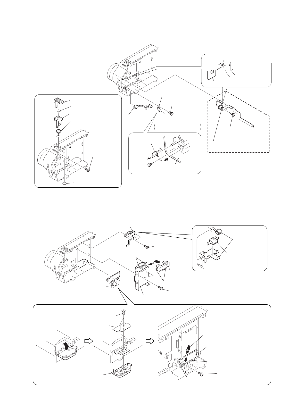
2-5. DC-IN CONNECTOR, MICROPHONE UNIT
)
2
T wo tapping
screws (M2
×
4)
4
Battery lid
8
Claw
6
Two claws
A
B
4
Two claws
3
Battery holder
6
Battery
terminal board (Remove it in the direction of the arrow
C
.)
5
Two claws
3
Hinge retainer
7
Remove the hinge assembly
in the direction of the arrow
A
.
9
Remove the hinge assembly
in the direction of the arrow
B
.
1
5
T apping
screw (M2
×
5)
2
T wo tapping
screws (M2
×
5)
7
T wo tapping
screws (M2
×
5)
8
1
Hinge assembly
2
Control switch
block
1
SW holder
REMOVING THE HINGE ASSEMBLY
REMOVING THE CONTROL
SWITCH BLOCK (zoom and shutter)
C
REMOVING THE
MICROPHONE UNIT
2
Microphone cover
4
Microphone cushion
3
Microphone holder
6
Microphone unit
1
T wo tapping
screws (M2
×
5)
3
DC-IN
connector
DC retainer
2
DC retainer
1
T wo tapping
screws (M2
PRECAUTION DURING
INSTALLATION
Cabinet (front)
assembly
(PRECAUTION DURING INSTALLATION
Align the switch position as shown.
Control switch block
(MF 330)
1
T wo tapping
screws (M2
×
5)
×
5)
Focus slider
2
Control switch block (MF 330)
(MVC-FD90)
5
Microphone sheet
2-6. HINGE ASSEMBLY, BATTERY TERMINAL BOARD
— 9 —
 Loading...