

Sony MVC-FD75 Service Manual
MVC-FD75
SERVICE MANUAL
Level 1
Ver 1.0 2001. 01
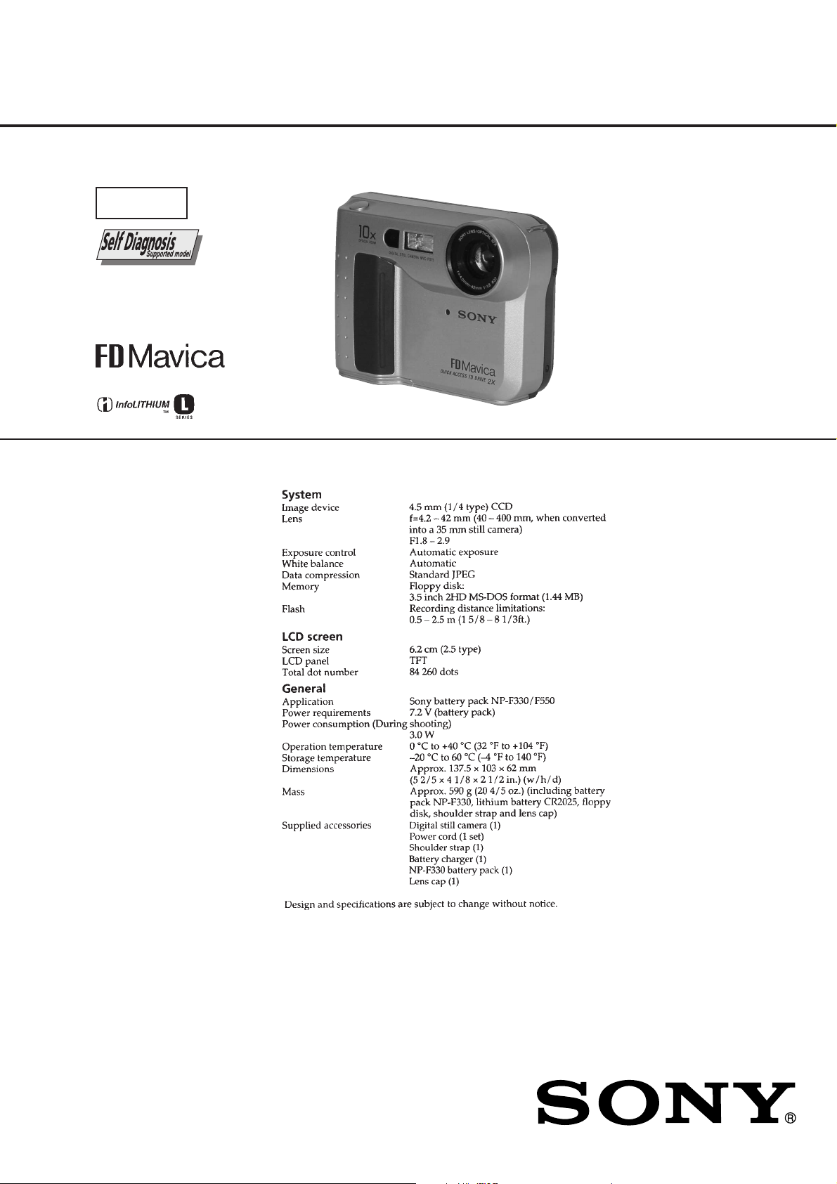
SPECIFICATIONS
AEP Model
UK Model
DIGITAL STILL CAMERA

• Floppy disk that can be used by the MVC-FD75
• Size : 3.5-inch
• T ype : 2 HD
• Capacity : 1.44 MB
• Format : MS-DOS format
(512 bytes × 18 sector)
(FD can be formatted by the MVC-FD75)
SAFETY-RELATED COMPONENT WARNING!!
COMPONENTS IDENTIFIED BY MARK 0 OR DOTTED
LINE WITH MARK 0 ON THE SCHEMA TIC DIAGRAMS
AND IN THE PARTS LIST ARE CRITICAL TO SAFE
OPERATION. REPLACE THESE COMPONENTS WITH
SONY PARTS WHOSE PART NUMBERS APPEAR AS
SHOWN IN THIS MANUAL OR IN SUPPLEMENTS PUBLISHED BY SONY.
SAFETY CHECK-OUT
After correcting the original service problem, perform the following
safety checks before releasing the set to the customer.
1. Check the area of your repair for unsoldered or poorly-soldered connections. Check the entire board surface for solder
splashes and bridges.
2. Check the interboard wiring to ensure that no wires are
“pinched” or contact high-wattage resistors.
3. Look for unauthorized replacement parts, particularly transistors, that were installed during a previous repair. Point them
out to the customer and recommend their replacement.
4. Look for parts which, though functioning, show obvious signs
of deterioration. Point them out to the customer and recommend their replacement.
5. Check the B+ voltage to see it is at the values specified.
6. Flexible Circuit Board Repairing
• Keep the temperature of the soldering iron around 270 ˚C
during repairing.
• Do not touch the soldering iron on the same conductor of
the circuit board (within 3 times).
• Be careful not to apply force on the conductor when sol-
dering or unsoldering.
– 2 –

TABLE OF CONTENTS
Section Title Page
SERVICE NOTE................................................................... 4
Self-diagnosis Display................................................... 5
1. MAIN PARTS
1. Ornamental Parts .......................................................... 6
2. DISASSEMBLY
2-1. Cabinet (Front) Block Assembly .................................. 7
2-2. FC-86 Board .................................................................. 7
2-3. Lens Block Assembly .................................................... 8
2-4. Motor Units .................................................................... 8
2-5. FDD Block Assembly..................................................... 8
2-6. PK-59 Board, LCD Module ........................................... 8
3. REPAIR PARTS LIST
3-1. Exploded Views ............................................................. 9
3-1-1. Cabinet (Front) Section........................................... 9
3-1-2. Cabinet (Rear) Section ........................................... 10
3-1-3. Lens Block Section ................................................... 11
4. GENERAL
Be Sure to Read Before Using Your Camera ......................... 12
Before Using Your Camera ..................................................... 13
Parts Identification................................................................... 13
Preparation .............................................................................. 14
Recording and Playing Back Images ...................................... 15
Changing the Mode Settings................................................... 16
Using Various Functions for Recording .................................. 19
Changing the Lithium Battery in the Camera......................... 19
Precautions.............................................................................. 19
Troubleshooting ....................................................................... 20
Self-diagnosis Display ............................................................. 21
– 3 –
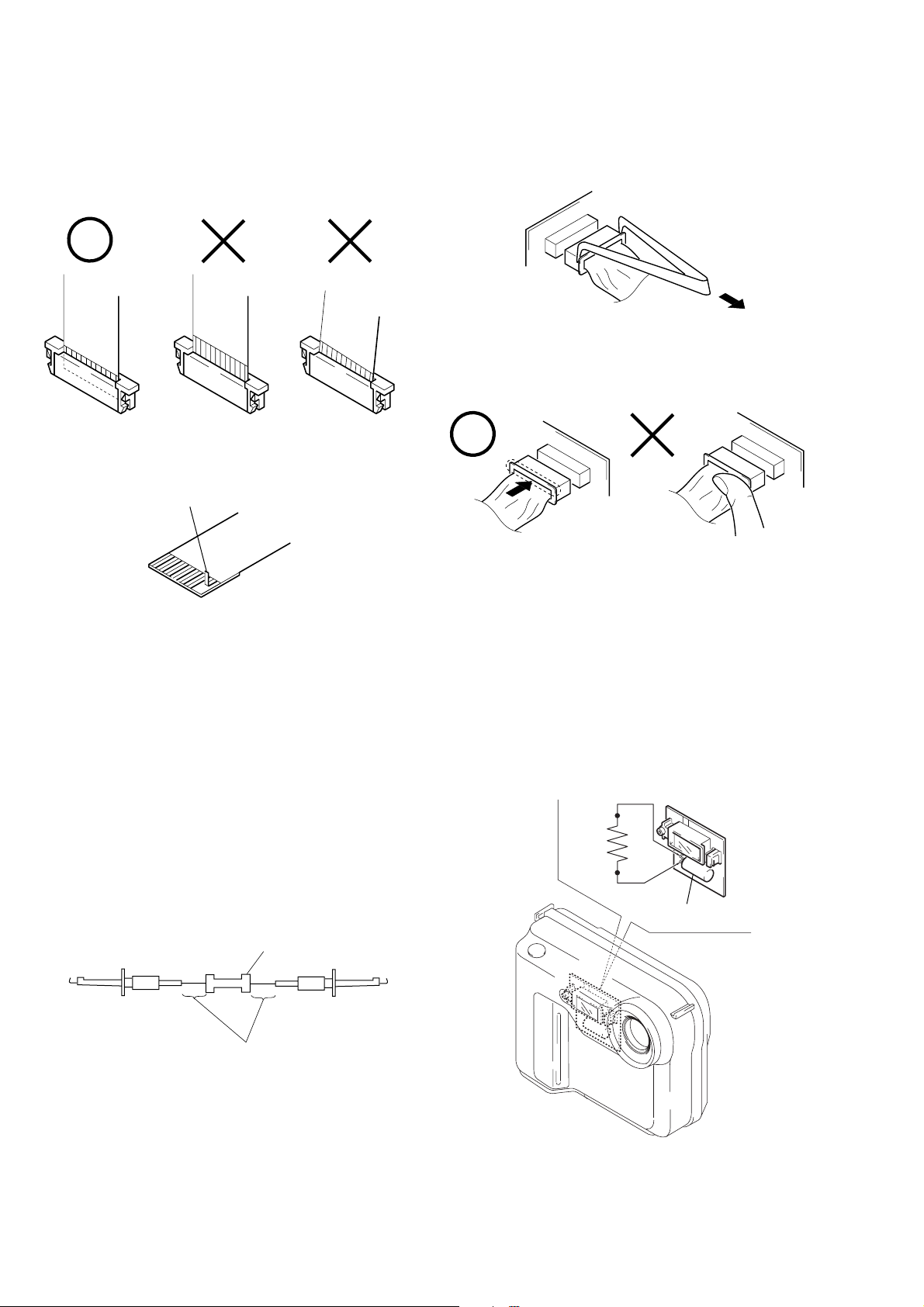
SERVICE NOTE
• NOTE FOR REPAIR
Make sure that the flat cable and flexible board are not cracked of
bent at the terminal.
Do not insert the cable insufficiently nor crookedly.
Cut and remove the part of gilt
which comes off at the point.
(Be careful or some pieces of
gilt may be left inside)
When remove a connector, don’t pull at wire of connector.
It is possible that a wire is snapped.
When installing a connector, don’t press down at wire of connector.
It is possible that a wire is snapped.
[Discharging of the FLASH unit’s charging capacitor]
The charging capacitor of the FLASH unit is charged up to the
maximum 300 V potential.
There is a danger of electric shock by this high voltage when the
battery is handled by hand. The electric shock is caused by the
charged voltage which is kept without discharging w hen the main
power of the MVC-FD75 is simply turned off. Ther efore, the remaining voltage must be discharged as described below.
Preparing the Short Jig
T o preparing the short jig. a small clip is attached to eac h end of a
resistor of 1 kΩ /1 W (1-215-869-11).
Wrap insulating tape fully around the leads of the resistor to prevent electrical shock.
1 kΩ/1 W
Wrap insulating tape.
Discharging the Capacitor
Short-circuit between the positive and the negative terminals of
charged capacitor with the short jig about 10 seconds.
R: 1 kΩ/1 W
(Part code:
1-215-869-11)
Capacitor
– 4 –
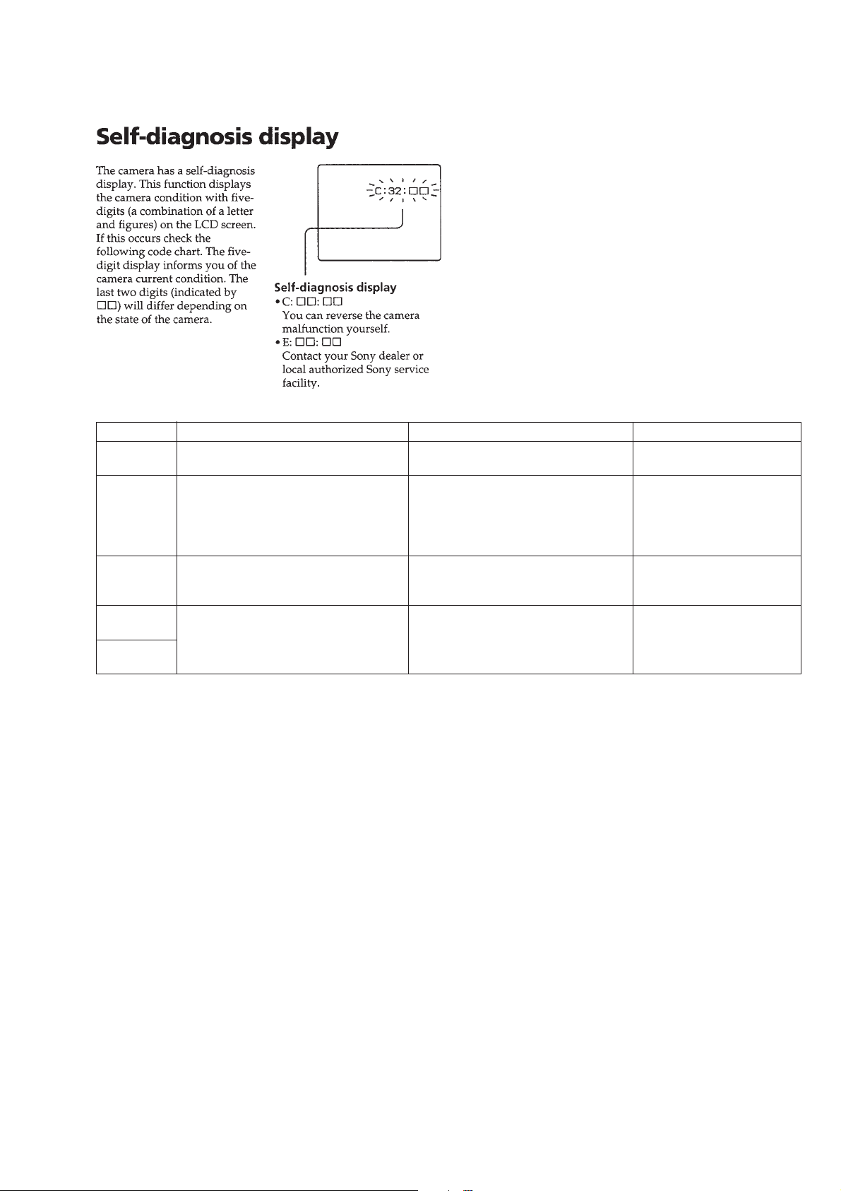
[Description on Self-diagnosis Display]
Note : The “Self-diagnosis” data is backed up by the coin lithiumbattery .
The data will be lost and initialized when the coin lithium battery
is removed.
Display Code
C:32:01
Change the disk and turn off the main
power then back on.
Countermeasure
Cause
Defective floppy disk.
• The type of floppy disk that cannot be
C:13:01
Replace the floppy disk.
Format the floppy disk with the MVCFD75.
used by this machine, is inserted.
(Such as 2DD)
• Data is damaged.
• Unformatted disk is inserted.
E:91:01
Checking of flash unit or replacement of
flash unit
Abnormality when flash is being
charged.
E:61:00
E61:10
Checking of lens drive circuit
When failed in the focus initialization.
[Power supplying Method]
Use the AC power adaptor (AC-VQ850/VQ850D) when supplying the power to this set.
Caution Display During Error
DRIVE ERROR
DISK ERROR
Flash LED
Flash display
Flashing at 3.2 Hz
—
– 5 –
MVC-FD75
1. MAIN PARTS
Note:
• Items marked “*” are not stocked since they are seldom required for routine service.
Some delay should be anticipated when ordering these items.
• The parts numbers of such as a cabinet are also appeared in this section.
Refer to the parts number mentioned below the name of parts to order.
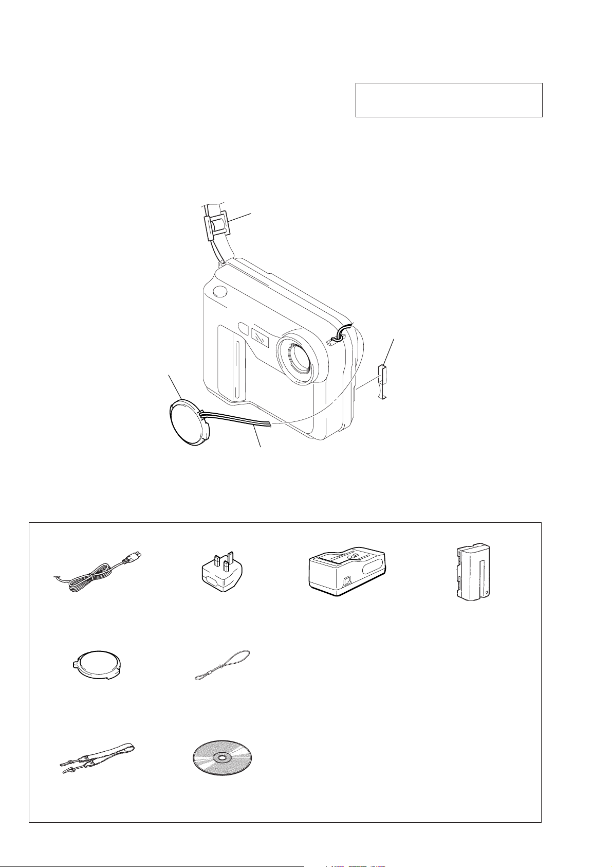
1. ORNAMENTAL PARTS
Shoulder strap
3-987-015-01
The components identified by mark 0 or dotted
line with mark 0 are critical for safety.
Replace only with part number specified.
CPC cover
3-050-489-01
Lens cap
X-3949-764-2
Cap string
3-067-797-01
Checking supplied accessories.
Check that the following accessories are supplied with your digital still camera.
Power cord (1)
0 1-769-608-11
Conversion plug 3P adaptor (1)
0 1-770-019-11 (UK)
BC-V615 battery charger (1)
0 A-7029-111-A
Other accessories
3-066-544-11 MANUAL, INSTRUCTION (ENGLISH)
3-066-544-21 MANUAL, INSTRUCTION (FRENCH,GERMAN)(AEP)
3-066-544-31 MANUAL, INSTRUCTION (SPANISH,PORTUGUESE)(AEP)
3-066-544-41 MANUAL, INSTRUCTION (ITALIAN,DUTCH)(AEP)
Lens cap (1)
X-3949-764-2
Cap string (1)
3-067-797-01
3-066-544-61 MANUAL, INSTRUCTION (SWEDISH)(AEP)
3-864-060-11 MANUAL, INSTRUCTION (for BC-V615)
3-864-060-21 MANUAL, INSTRUCTION (for BC-V615)
NP-F330 battery pack (1)
0 A-7094-141-B
(ENGLISH, FRENCH, GERMAN, SPANISH)
(ITALIAN, DUTCH, PORTUGUESE, RUSSIAN)
Shoulder strap (1)
3-987-015-01
CD-ROM (1)
3-066-676-01
– 6 –
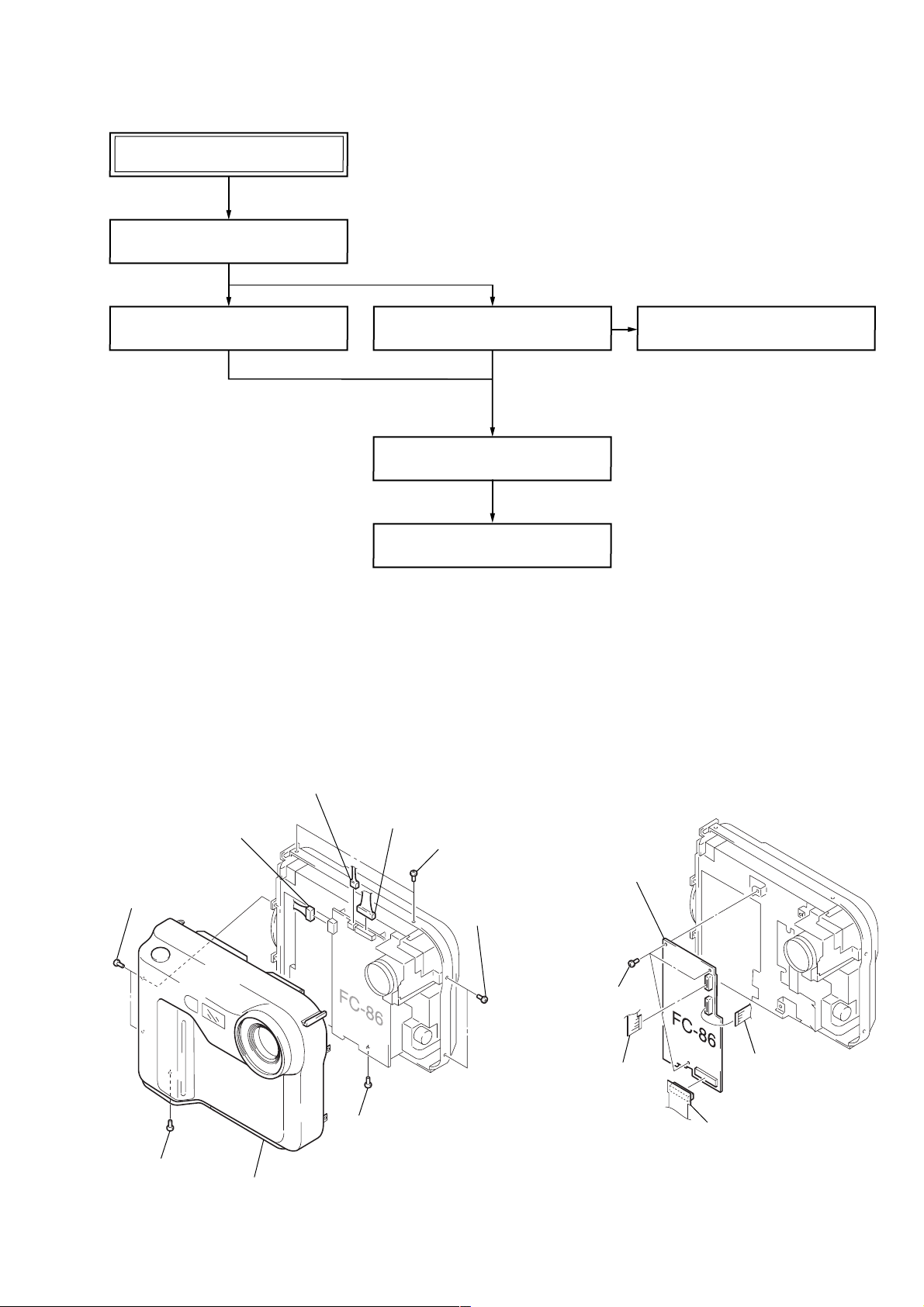
2. DISASSEMBLY
• This set can be disassembled in the order shown below.
MVC-FD75
2-1. CABINET (FRONT) BLOCK ASSEMBLY
(Page 7)
MVC-FD75
2-2. FC-86 BOARD
(Page 7)
2-3. LENS BLOCK ASSEMBLY
(Page 8)
2-5. FDD BLOCK ASSEMBLY
(Page 8)
2-6. PK-59 BOARD, LCD MODULE
(Page 8)
Note: Follow the disassembly procedure in the numerical order given.
2-1. CABINET (FRONT) BLOCK ASSEMBLY
8 Connector
(CN907)
7 Connector
(CN901)
1 T wo screws
(M2)
9 Connector
(CN910)
2 T wo screws
(M2)
3 T wo screws
(M2)
2-4. MOTOR UNITS
(Page 8)
2-2. FC-86 BOARD
5 FC-86 board
5 screw
(M2)
6 Cabinet (front) block assembly
4 screw
(M2)
– 7 –
4 Three screws
(M2)
3 FP-34 frexible board
(CN101)
1 Frexible board
(CN401)
2 FP-35 frexible board
(CN601)
 Loading...