

Sony MVC-FD100, MVC-FD100H, MVC-FD200, MVC-FD200H Service Manual
MVC-FD100/FD100H/FD200/FD200H
SERVICE MANUAL
Level 2
Ver 1.4 2003. 09
Photo: MVC-FD200
This service manual contains information for Japanese model as well.
When the machine needs to be repaired,
please refer to page 7 to discriminate the
type of CCD.
On the FC-89 board
This service manual procides the information that is premised the
circuit board replacement service and not intended repair inside the
FC-89 board.
Therefore, schematic diagram, printed wiring board and electrical
parts list of the FC-89 board are not shown.
The following pages are not shown.
US Model
MVC-FD100/FD100H/FD200/FD200H
Canadian Model
MVC-FD100/FD200
AEP Model
UK Model
MVC-FD200
E Model
Australian Model
Japanese Model
MVC-FD100/FD200
Brazilian Model
MVC-FD100
FC-89 board
Schematic diagram...................................Pages 4-11 to 4-30
Printed wiring board .................................Pages 4-43 to 4-46
Electrical parts list ....................................Pages 6-9 to 6-15
The above-described information is shown in service manual
Level 3.
System
Image device
6.64 mm (1/2.7 type)
Color CCD
Effective pixels number
of camera
MVC-FD100:
Approx. 1 228 000 pixels
MVC-FD200:
Approx. 1 976 000 pixels
Lens
3× zoom lens
f=6.4 –19.2 mm (9/32 –
25/32 inches)
(41 – 123 mm
(1 5/8 –47/8 inches) when
convertedinto a 35 mm still
camera)
F=3.8–3.9
Exposure control
Automaticexposure
White balance
Automatic, Indoor, Outdoor,
Hold
Data system
Movie: MPEG
Still: JPEG, GIF (in TEXT
mode, Clip Motion), TIFF
MPEG
Recording medium
Floppy disk:
3.5-inch 2HD MS-DOS
format (1.44 MB)
“Memory Stick”
Flash
Recommended recording
distance (ISO set to AUTO):
0.5 m to 2.0 m (1 2/3 feet to
62/3 feet)
Input and Output
connector
VIDEO OUT
Minijack
Video: 1 Vp-p, 75 Ω,
unbalanced, sync negative
USB jack
mini-B
LCD screen
LCDpanel
6.2cm(2.5 type)
TFT (Thin Film Transistor
active matrix) drive
Total number of dots
123 200 (560×220) dots
General
Application
Sony battery pack NP-F330
(supplied)/F550 (Optional)
Power requirements
7.2 V
Power consumption
(During shooting and
LCD backlight is on)
MVC-FD100: 3.5 W
MVC-FD200: 3.6 W
SPECIFICATIONS
Operating temperature
0°Cto40°C(32°Fto104°F)
Storage temperature
–20°Cto+60°C (–4°Fto
+140°F)
Dimensions (Approx.)
142 × 104 × 77 mm (5 1/2 ×
4 × 3 inches) (w/h/d)
Mass (Approx.)
645 g (1 lb 7 oz)
(including NP-F330 battery
pack, floppy disk and lens
cap, etc.)
AC-L10A/L10B
AC power adaptor
Power requirements
100 to 240 V AC, 50/60 Hz
Rated output voltage
DC 8.4 V, 1.5 A in operating
mode
Operating temperature
0°Cto40°C(32°Fto104°F)
Storage temperature
−20°Cto+60°C(−4°Fto
+140°F)
Dimensions (Approx.)
125×39×62 mm (5×19/16×
21/2 inches) (w/h/d)
Mass (Approx.)
280 g (10 oz)
NP-F330 battery
pack
Battery type
Lithium ion
Maximum output
voltage
DC 8.4 V
Mean output voltage
DC 7.2 V
Capacity
5.0 Wh (700mAh)
Operating temperature
0°Cto40°C(32°Fto104°F)
Dimensions (Approx.)
38.4×20.6×70.8 mm
(1 9/16×13/16×27/8 inches)
(w/h/d)
Mass (Approx.)
70 g (2 oz)
Accessories
AC-L10A/L10B
AC power adaptor (1)
Power cord (mains lead) (1)
USB cable (1)
NP-F330 battery pack (1)
VIDEO connecting cable (1)
Shoulder strap (1)
Lens cap (1)
Lens cap strap (1)
CD-ROM (SPVD-008 USB
Driver)(1)
Operating instructions (1)
Design and specifications
aresubject to change
without notice.
DIGITAL STILL CAMERA

MVC-FD100/FD100H/FD200/FD200H
SAFETY-RELATED COMPONENT WARNING!!
COMPONENTS IDENTIFIED BY MARK 0 OR DOTTED
LINE WITH MARK 0 ON THE SCHEMATIC DIAGRAMS
AND IN THE PARTS LIST ARE CRITICAL TO SAFE
OPERATION. REPLACE THESE COMPONENTS WITH
SONY PARTS WHOSE PART NUMBERS APPEAR AS
SHOWN IN THIS MANUAL OR IN SUPPLEMENTS PUBLISHED BY SONY.
SAFETY CHECK-OUT
After correcting the original service problem, perform the following
safety checks before releasing the set to the customer.
1. Check the area of your repair for unsoldered or poorly-soldered connections. Check the entire board surface for solder
splashes and bridges.
2. Check the interboard wiring to ensure that no wires are
“pinched” or contact high-wattage resistors.
3. Look for unauthorized replacement parts, particularly transistors, that were installed during a previous repair. Point them
out to the customer and recommend their replacement.
4. Look for parts which, though functioning, show obvious signs
of deterioration. Point them out to the customer and recommend their replacement.
5. Check the B+ voltage to see it is at the values specified.
6. Flexible Circuit Board Repairing
• Keep the temperature of the soldering iron around 270 ˚C
during repairing.
• Do not touch the soldering iron on the same conductor of
the circuit board (within 3 times).
• Be careful not to apply force on the conductor when sol-
dering or unsoldering.
ATTENTION AU COMPOSANT AYANT RAPPORT
À LA SÉCURITÉ!
LES COMPOSANTS IDENTIFIÉS P AR UNE MARQUE 0
SUR LES DIAGRAMMES SCHÉMATIQUES ET LA LISTE
DES PIÈCES SONT CRITIQUES POUR LA SÉCURITÉ
DE FONCTIONNEMENT. NE REMPLACER CES COMPOSANTS QUE PAR DES PIÈCES SONY DONT LES
NUMÉROS SONT DONNÉS DANS CE MANUEL OU
DANS LES SUPPLÉMENTS PUBLIÉS PAR SONY.
UNLEADED SOLDER
Boards requiring use of unleaded solder are printed with the leadfree mark (LF) indicating the solder contains no lead.
(Caution: Some printed circuit boards may not come printed with
the lead free mark due to their particular size)
: LEAD FREE MARK
Unleaded solder has the following characteristics.
• Unleaded solder melts at a temperature about 40 ˚C higher than
ordinary solder.
Ordinary soldering irons can be used but the iron tip has to be
applied to the solder joint for a slightly longer time.
Soldering irons using a temperature regulator should be set to
about 350 ˚C .
Caution: The printed pattern (copper foil) may peel away if the
heated tip is applied for too long, so be careful!
• Strong viscosity
Unleaded solder is more viscous (sticky , less prone to flow) than
ordinary solder so use caution not to let solder bridges occur
such as on IC pins, etc.
• Usable with ordinary solder
It is best to use only unleaded solder but unleaded solder may
also be added to ordinary solder.
– 2 –

MVC-FD100/FD100H/FD200/FD200H
• Floppy disk that can be used by the MVC-FD100/FD200
• Size : 3.5-inch
• T ype : 2 HD
• Capacity : 1.44 MB
• Format : MS-DOS format
(512 bytes × 18 sector)
(FD can be formatted by the MVC-FD100/FD200)
Table for differences of function
Model MVC-FD100 MVC-FD200
Destination
Effective pixels number
of camera
CD board (Note 1)
Note 1: Type of CCD imager is different according to the CD board in MVC-FD100.
Refer to page 7 to discriminate the type of CCD.
Note 2: MVC-FD100H/FD200H are the same as MVC-FD100/FD200 (US model) except packing materials.
Therefore, information about MVC-FD100/FD200 (US model) in the text is applied.
US, Canadian, US, Canadian,
E, Australian, J AEP, UK, E, J
Approx. 1228 k pixels Approx. 1976 k pixels Approx. 1228 k pixels Approx. 1976 k pixels
CD-379 CD-390
(TYPE PA) (TYPE SO) (TYPE PA) (TYPE SO)
CD-390
MVC-FD100H MVC-FD200H
(Note 2) (Note 2)
US US
CD-379 CD-390
CD-390
– 3 –

MVC-FD100/FD100H/FD200/FD200H
TABLE OF CONTENTS
Section Title Page Section Title Page
SERVICE NOTE................................................................... 6
Self-diagnosis Display .......................................................... 8
1. GENERAL
Introduction.............................................................................. 1-1
Identifying the Parts................................................................. 1-2
Preparing the Power Supply ................................................... 1-2
Setting the Date and Time ....................................................... 1-3
Inserting a Floppy Disk............................................................ 1-4
Inserting a “Memory Stick” ...................................................... 1-4
Recording Still Images ............................................................ 1-4
Recording Moving Images ...................................................... 1-6
Playing Back Still Images........................................................ 1-6
Playing Back Moving Images .................................................. 1-6
Viewing Images Using a Computer......................................... 1-7
Image File Storage Destinations and Image File Names....... 1-9
Viewing Images Using “ImageMixer” ...................................... 1-10
Before Performing Advanced Operations ............................... 1-12
Various Recording ................................................................... 1-14
Various Playback..................................................................... 1-17
Editing ..................................................................................... 1-18
As an External Drive................................................................ 1-20
Additional Information ............................................................. 1-21
Troubleshooting ....................................................................... 1-22
Warning and Notice Messages ............................................... 1-23
Self-diagnosis Display ............................................................. 1-24
LCD Screen Indicators ............................................................ 1-24
2. DISASSEMBLY
2-1. Cabinet (Rear) Block Assembly .................................... 2-1
2-2. USB Connector Block ................................................... 2-2
2-3. FC-89 Board .................................................................. 2-2
2-4. FDD ............................................................................... 2-3
2-5. FDD Block Assembly..................................................... 2-3
2-6. Lens Block Assembly .................................................... 2-4
2-7. PK-61 Board .................................................................. 2-5
2-8. LCD Module................................................................... 2-5
2-9. The Way of Disassembling the FDD............................. 2-7
2-10. Circuit Boards Location ................................................. 2-15
3. BLOCK DIAGRAMS
3-1. Overall Block Diagram .................................................. 3-1
3-9. Power Block Diagram 1 ................................................. 3-17
3-10. Power Block Diagram 2................................................. 3-19
4. PRINTED WIRING BOARDS AND
SCHEMATIC DIAGRAMS
4-1. Frame Schematic Diagrams ......................................... 4-3
Frame Schematic Diagram (1/2)................................... 4-3
Frame Schematic Diagram (2/2)................................... 4-5
4-2. Schematic Diagrams ..................................................... 4-7
CD-379 Schematic Diagram ......................................... 4-7
CD-390 Schematic Diagram ......................................... 4-9
PK-61 (MODE SWITCH, VIDEO OUT)
Schematic Diagram ....................................................... 4-31
PK-61 (LCD DRIVE, TIMING GENERATOR)
Schematic Diagram ....................................................... 4-33
PK-61 (BACK LIGHT DRIVE) Schematic Diagram ...... 4-35
FU-159 Schematic Diagram.......................................... 4-37
4-3. Printed Wiring Boards ................................................... 4-39
CD-379 Printed Wiring Board ....................................... 4-39
CD-390 Printed Wiring Board ....................................... 4-41
PK-61 Printed Wiring Board.......................................... 4-47
FU-159 Printed Wiring Board........................................ 4-51
4-4. Waveforms ..................................................................... 4-53
4-5. Par ts Location ............................................................... 4-58
5. ADJUSTMENTS
1-1. Adjusting Items when Replacing
Main Parts and Boards.................................................. 5-2
5-1. Camera Section Adjustments........................................ 5-3
1-1. Preparations Before Adjustment ................................... 5-3
1-1-1. List of Service Tools ................................................. 5-3
1-1-2. Preparations............................................................. 5-4
1-1-3. Discharging of the Flashlight Power Supply............ 5-4
1-1-4. Precautions .............................................................. 5-6
1. Setting the Switch .................................................... 5-6
2. Order of Adjustments ............................................... 5-6
3. Subjects.................................................................... 5-6
4. Preparing the Flash Adjustment Box ....................... 5-7
1-2. Initialization of B, D, E, F, 7, 9 Page Data .................... 5-8
1-2-1. Initialization of D Page Data .................................... 5-8
1. Initializing D Page Data............................................ 5-8
2. Modification of D Page Data .................................... 5-8
3. D Page Table ............................................................ 5-9
1-2-2. Initialization of B, E, F, 7,9 Page Data..................... 5-10
1. Initializing B, E, F, 7 ,9 Page Data ........................... 5-10
2. Modification of B, E, F, 7,9 Page Data..................... 5-10
3. B Page Table ............................................................ 5-10
4. E Page Table ............................................................ 5-10
5. F Page Table ............................................................ 5-11
6. 7 Page Table ............................................................ 5-13
7. 9 Page Table ............................................................ 5-14
1-3. Video System Adjustments ........................................... 5-15
1. Video Sync Level Adjustment ....................................... 5-15
2. Video Burst Level Adjustment....................................... 5-15
1-4. Camera System Adjustments........................................ 5-16
Data Setting During Camera System Adjustments .............. 5-16
Picture Frame Setting ........................................................... 5-17
Check on the Oscilloscope ................................................... 5-17
1. HALL Adjustment........................................................... 5-18
2. Flange Back Adjustment
(Using the Minipattern Box) .......................................... 5-19
3. Flange Back Adjustment
(Using the Flange Back Adjustment Chart and
Subject More than 500 m Away)................................... 5-20
4. Flange Back Check ....................................................... 5-21
5. F No. Compensation ..................................................... 5-22
6. Mechanical Shutter Adjustment .................................... 5-22
7. Light Value Adjustment.................................................. 5-23
8. Mixed Color Cancel Adjustment.................................... 5-24
9. Auto White Balance Standard Data Input..................... 5-24
10. Auto White Balance Adjustment ................................... 5-25
11. Auto White Balance 5800K Check................................ 5-26
12. Auto White Balance 3200K Check................................ 5-27
13. Color Reproduction Adjustment .................................... 5-28
14. Color Reproduction Check ............................................ 5-29
15. CCD White Defect Compensation ................................ 5-30
16. CCD Black Defect Compensation ................................. 5-31
17. Strobe White Balance Adjustment ................................ 5-32
18. CCD Linearity Check..................................................... 5-33
1-5. LCD System Adjustments ............................................. 5-34
1. LCD Initial Data Input .................................................... 5-35
2. VCO Adjustment (PK-61 Board) ................................... 5-36
3. Black Limit Adjustment (PK-61 Board) ......................... 5-37
4. Bright Adjustment (PK-61 Board).................................. 5-37
5. Contrast Adjustment (PK-61 Board) ............................. 5-38
6. VG Center Adjustment (PK-61 Board).......................... 5-38
7. P-SIG Level Adjustment (PK-61 Board) ....................... 5-39
8. V-COM Adjustment (PK-61 Board) ............................... 5-40
9. White Balance Adjustment (PK-61 Board) ................... 5-41
1-6. System Control System Adjustments ........................... 5-42
1. Battery Down Adjustment.............................................. 5-42
2. ZOOM Center Adjustment............................................. 5-43
3. Alignment Check (FDD Unit)......................................... 5-43
5-2. Ser vice Mode ................................................................ 5-44
2-1. Adjusting Remote Commander ..................................... 5-44
– 4 –

Section Title Page
1. Used the Adjusting Remote Commander ..................... 5-44
2. Precautions upon Using the Adjusting
Remote Commander ..................................................... 5-44
2-2. Data Process ................................................................. 5-45
2-3. Service Mode ................................................................ 5-46
1. Setting the Test Mode ................................................... 5-46
2. Bit Value Discrimination ................................................ 5-46
3. Switch Check (1) ........................................................... 5-46
4. Switch Check (2) ........................................................... 5-46
5. Switch Check (3) ........................................................... 5-47
6. LED Check .................................................................... 5-47
7. Self Diagnosis Code...................................................... 5-47
6. REPAIR PARTS LIST
6-1. Exploded Views ............................................................. 6-1
6-1-1. Cabinet (Front) Section............................................ 6-1
6-1-2. Cabinet (Front) Assembly ........................................ 6-2
6-1-3. FDD Block Section ................................................... 6-3
6-1-4. Cabinet (Rear) Section ............................................ 6-4
6-1-5. Cabinet (Rear) Assembly......................................... 6-5
6-1-6. Lens Block Section ................................................... 6-6
6-2. Electrical Parts List........................................................ 6-7
MVC-FD100/FD100H/FD200/FD200H
* The color reproduction frame is shown on page 151.
– 5 –
MVC-FD100/FD100H/FD200/FD200H
SERVICE NOTE
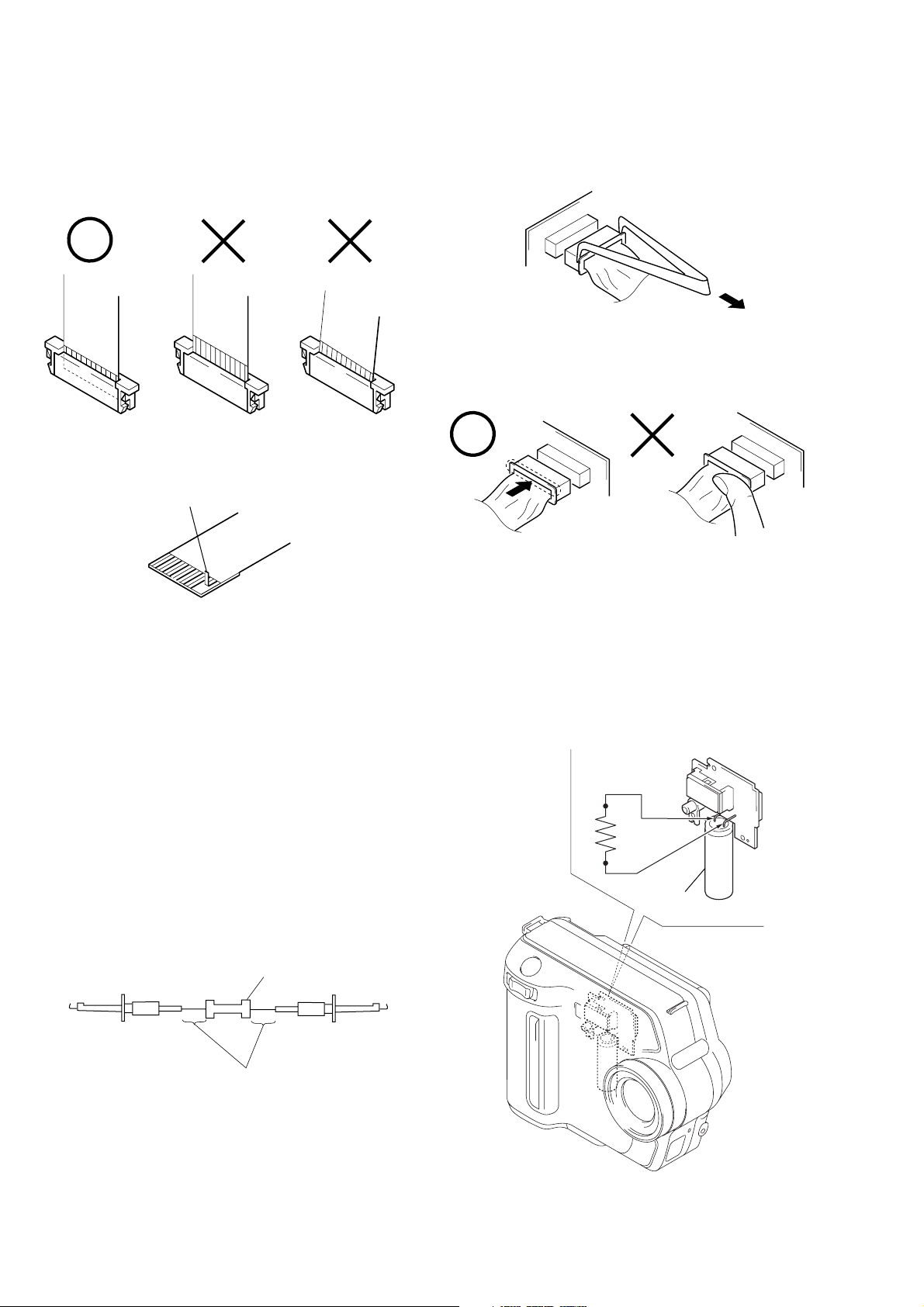
• NOTE FOR REPAIR
Make sure that the flat cable and flexible board are not cracked of
bent at the terminal.
Do not insert the cable insufficiently nor crookedly.
Cut and remove the part of gilt
which comes off at the point.
(Be careful or some pieces of
gilt may be left inside)
When remove a connector, don’t pull at wire of connector.
It is possible that a wire is snapped.
When installing a connector, don’t press down at wire of connector.
It is possible that a wire is snapped.
[Discharging of the FLASH unit’s charging capacitor]
The charging capacitor of the FLASH unit is charged up to the
maximum 300 V potential.
There is a danger of electric shock by this high voltage when the
battery is handled by hand. The electric shock is caused by the
charged voltage which is kept without discharging w hen the main
power of the MVC-FD100/FD200 is simply turned off. Therefore, the remaining voltage must be discharged as described below.
Preparing the Short Jig
T o preparing the short jig. a small clip is attached to eac h end of a
resistor of 1 kΩ /1 W (1-215-869-11).
Wrap insulating tape fully around the leads of the resistor to prevent electrical shock.
1 kΩ/1 W
Wrap insulating tape.
Discharging the Capacitor
Short-circuit between the positive and the negative terminals of
charged capacitor with the short jig about 10 seconds.
R: 1 kΩ/1 W
(Part code:
1-215-869-11)
Capacitor
– 6 –
[CCD type discrimination] (MVC-FD100 only)
Note: About CD board, FC-89 board and CCD imager, discrimi-
nate CCD type on the machine, and replace the same type.
MVC-FD100/FD100H/FD200/FD200H
• Discrimination method by adjusting remote commander.
Checking method:
1) Select page: 6, address: 03
2) By checking the data value of display data, the type of CCD
can be discriminated.
Data CCD Type
15 TYPE PA
17 TYPE SO
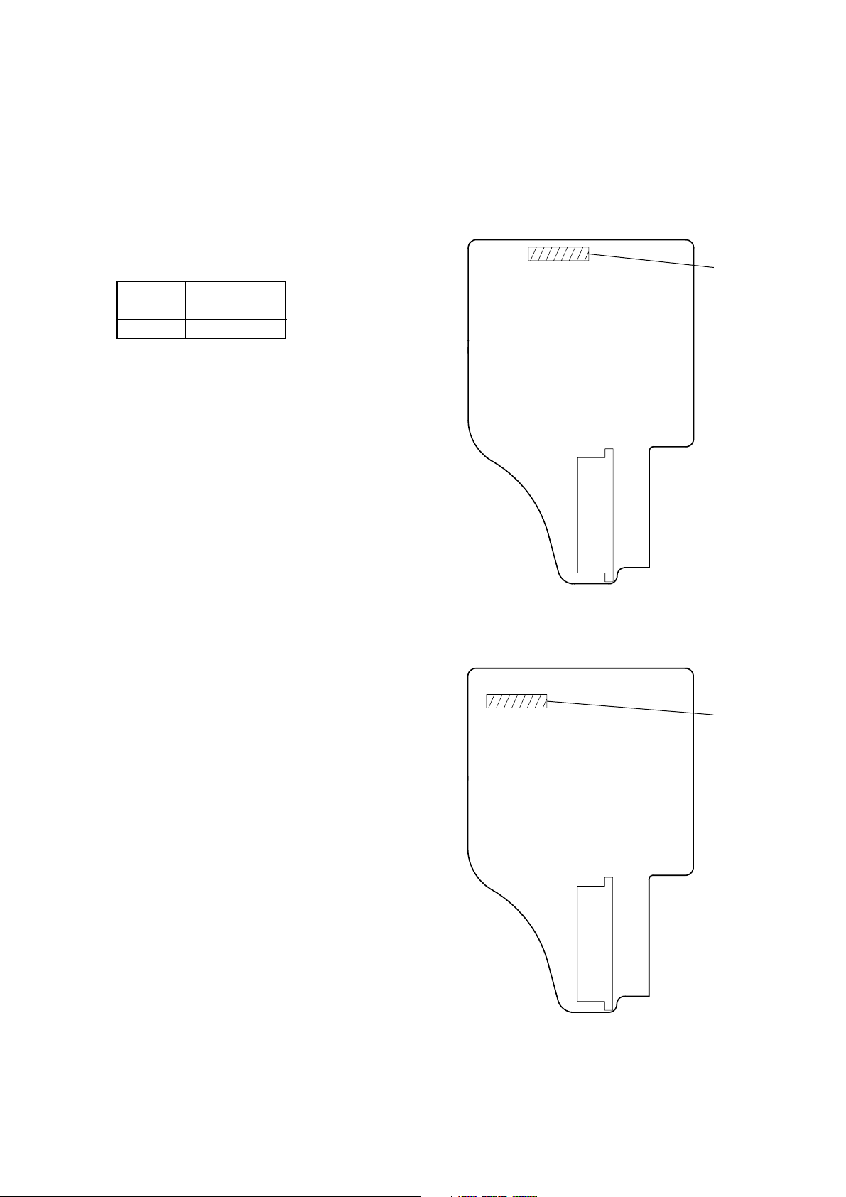
• Discrimination method by CD board (Board name check).
– CD-379 Board (Side A) –
CD-379: TYPE P A
– CD-390 Board (Side A) –
CD-390: TYPE SO
– 7 –

MVC-FD100/FD100H/FD200/FD200H
[Description on Self-diagnosis Display]
Note : The “Self-diagnosis” data is backed up by the coin lithiumbattery.
The data will be lost and initialized when the coin lithium battery
is removed.
Display Code
C:32:01
C:13:01
E:91:01
E:61:00
E61:10
Note : The error code is cleared if the battery is removed, except defective flash, unit.
*1: When the flash charging failed, Page: D, Address: 67, Data: 04 are written.
After repair, be sure to write Page: D, Address: 67, Data: 00.
[Power supplying Method]
Use the AC power adaptor (AC-L10A) when supplying the power to this set.
Change the disk and turn off the main
power then back on.
Replace the floppy disk or “Memory
Stick”.
Format the floppy disk or “Memory
Stick” with the MVC-FD100/FD200.
Checking of flash unit or replacement of
flash unit
Checking of lens drive circuit
Countermeasure
Cause
Defective floppy disk.
• The type of floppy disk that cannot be
used by this machine, is inserted.
(Such as 2DD)
• Data is damaged.
• Unformatted disk or “Memory Stick”
is inserted.
Abnormality when flash is being
charged.
When failed in the focus initialization.
Caution Display During Error
DRIVE ERROR
DISK ERROR
MEMORY STICK ERROR
Flash LED
*1
Flash display
Flashing at 3.2 Hz
—
– 8 –
SECTION 1
GENERAL
MVC-FD100/FD100H/FD200/FD200H
This section is extracted from MVCFD100/FD200 instruction manual.
.
WARNING
Toprevent fire or shock hazard, do
not expose the unit to rain or
moisture.
For the Customers in the
U.S.A.
This symbol is intended to
alert theusertothe presence
of uninsulated “dangerous
voltage” within the
product’s enclosure that
maybeofsufficient
magnitude to constitute a
risk of electric shock to
persons.
This symbol is intended to
alert theusertothe presence
of important operating and
maintenance (servicing)
instructions in the literature
accompanying the
appliance.
If youhaveany questions about this product,
you may call:
Sony Customer Information Center
1-800-222-SONY (7669)
The number below is for the FCC related
matters only.
2
Regulatory Information
Declaration of Conformity
Trade Name: SONY
Model No.: MVC-FD100
Responsible Party:Sony ElectronicsInc.
Address: 680 Kinderkamack
Telephone No.: 201-930-6972
This devicecomplies with Part15of the FCC
Rules. Operation issubjecttothe following
two conditions:(1)Thisdevice may not
cause harmfulinterference,and(2) this
devicemustaccept any interference received,
including interferencethatmaycause
undesired operation.
Declaration of Conformity
Trade Name: SONY
Model No.: MVC-FD200
Responsible Party:Sony ElectronicsInc.
Address: 680 Kinderkamack
Telephone No.: 201-930-6972
This devicecomplies with Part15of the FCC
Rules. Operation issubjecttothe following
two conditions:(1)Thisdevice may not
cause harmfulinterference,and(2) this
devicemustaccept any interference received,
including interferencethatmaycause
undesired operation.
CAUTION
You are cautioned that any changes or
modifications not expressly approved
in this manual could void your
authority to operate this equipment.
Note:
This equipment has been testedandfoundto
comply with the limits for a Class B digital
device, pursuant to Part 15 of the FCC
Rules. These limits are designedtoprovide
reasonable protection against harmful
interferenceina residential installation.This
equipment generates, uses, and can radiate
radio frequency energy and, if not installed
and used in accordance withthe
instructions, may cause harmfulinterference
to radio communications. However, there is
Road, Oradell, NJ,
07649 USA
Road, Oradell, NJ,
07649 USA
no guarantee that interference will not occur
in a particular installation.Ifthisequipment
does cause harmful interference to radio or
television reception,whichcanbe
determinedbyturning the equipmentoff and
on, the user is encouraged totrytocorrect
the interference by one or moreofthe
following measures:
— Reorient or relocate the receiving antenna.
—Increasetheseparation between the
equipment and receiver.
—Connecttheequipmentintoan outlet on
a circuit differentfromthattowhichthe
receiver is connected.
—Consultthe dealer or an experienced
radio/TV technician for help.
The supplied interfacecablemustbeused
with the equipment in order to comply with
the limits for a digital device pursuantto
Subpart B of Part 15 of FCC Rules.
For the Customers in the
U.S.A. and Canada
RECYCLING LITHIUM-ION
BATTERIES
Lithium-Ion batteries are
recyclable.
Youcanhelp preserve our
environmentbyreturning your
used rechargeable batteries to
the collectionandrecyclinglocation nearest
you.
For more information regarding recycling of
rechargeable batteries, call toll free
1-800-822-8837, or
visit http://www.rbrc.org/.
Caution:Do not handle damaged or leaking
Lithium-Ion batteries.
CAUTION
TOPREVENTELECTRIC SHOCK, DO NOT
USE THIS POLARIZED ACPLUGWITH
AN EXTENSION CORD, RECEPTACLE OR
OTHER OUTLETUNLESSTHEBLADES
CAN BE FULL YINSERTED TO PREVENT
BLADE EXPOSURE.
NOTICE FOR THE
CUSTOMERS IN THE UNITED
KINGDOM
A moulded plugcomplyingwithBS 1363 is
fitted to this equipment for your safety and
convenience.
Should the fuse in the plug suppliedneedto
be replaced, a 5 AMP fuse approved by
ASTAorBSItoBS1362,(i.e.markedwith
or mark) must be used.
If the plug supplied with thisequipmenthas
a detachable fuse cover,besuretoattachthe
fuse cover afteryouchangethefuse.Never
use the plug without the fusecov er. Ifyou
should lose the fuse cover,please contact
your nearest Sony servicestation.
For the Customers in
Germany
Directive:EMCDirective 89/336/EEC.92/
31/EEC
This equipment complies with the EMC
regulations when usedunderthefollowing
circumstances:
• Residential area
• Business district
• Light-industry district
(This equipment complies withtheEMC
standard regulations EN55022 Class B.)
Attention for the Customers in
Europe
This product has been tested and found
compliant with the limits sets out on the
EMC Directive for using connection cables
shorter than 3 meters (9.8 feet).
The electromagnetic fieldsatthespecific
frequencies may influence the picture ofthis
camera.
3
Be sure to read the following
before using your camera
Operating instructions
Before operating the unit, pleasereadthis
manual thoroughly, and retain it for future
reference.
As you read through this manual,buttons
and settings on the camera are shownin
capital letters.
e.g. Press DISPLAY.
Trial recording
Before yourecordone-time events,youmay
want to make a trial recording to make sure
that the camera is working correctly.
No compensation for contents of
the recording
The recorded images cannot be
compensated if recording or playback
cannot beperformed duetoa trouble of your
camera or recording medium.
Notes on imagedata compatibility
of the “Memory Stick”
• This cameraconformswiththeDesign rule
for Camera File system universal standard
established by the JEITA (Japan
Electronics and Information Technology
Industries Association). You cannot play
back on your camera still imagesrecorded
on other equipment (DCR-TRV890E/
TRV900/TRV900E, DSC-D700, DSCD770) that does not conform withthis
universal standard. (These models are not
sold in some areas.)
• Playback of images recorded with your
camera on other equipment and playback
of images recorded or edited with other
equipment on your camera are not
guaranteed.
Precaution on copyright
Television programs, films,videotapes, and
other materials may be copyrighted.
Unauthorized recording of suchmaterials
may be contrary to the provision ofthe
copyright laws.
Do not shake or strike the camera
In addition to malfunctions and inability to
record images, this may renderthefloppy
disksorthe“Memory Stick”s unusable or
image data breakdown, damage or lossmay
occur.
LCD screen, finder(only models
with a finder) and lens
• The LCD screen and thefinderare
manufactured using extremely highprecision technology so over 99.99% of
the pixels are operational for effective use.
However,there may be some tiny black
points and/or bright points (white,red,
blue or green in color) that constantly
appear on the LCD screen and the finder.
These points are normal in the
manufacturing process and do not affect
the recording in any way.
• Be careful when placing the camera near a
window or outdoors.ExposingtheLCD
screen, the finder or the lens to direct
sunlight for long periods may cause
malfunctions.
Do not getthe camera wet
When taking pictures outdoors in the rain or
under similar conditions,becarefulnotto
get the camera wet. If moisture
condensation occurs, refer to page83and
follow the instructionsonhowtoremove it
before using the camera.
Back up recommendation
Toavoid the potential risk of data loss,
always copy (back up) data to a disk.
When the camerais used for long
periods
Note that the camera body may become hot.
Introduction
Check images after recording
Recording still images:
page 18
Playing back still images:
page 24
Deleting images(DELETE):
page 75
Capture images with your computer
You can copy images onto your computer and view and modify images or attach
images to e-mail on your computer using the supplied USB cable and application
software.
Viewingimages using a computer: page 27
Recording still images for e-mail (E-MAIL): page 61
Records a moving picture
The digital still camera can record a moving picture for maximum 60 seconds. Your
camera does not record sound.
Recording moving images: page 23
Select from various recording modes
Creating Clip Motion Files: page 59
Recording text documents (TEXT): page 62
Recording still images as uncompressed files (TIFF): page 63
4
5
1-1
MVC-FD100/FD100H/FD200/FD200H
Getting started
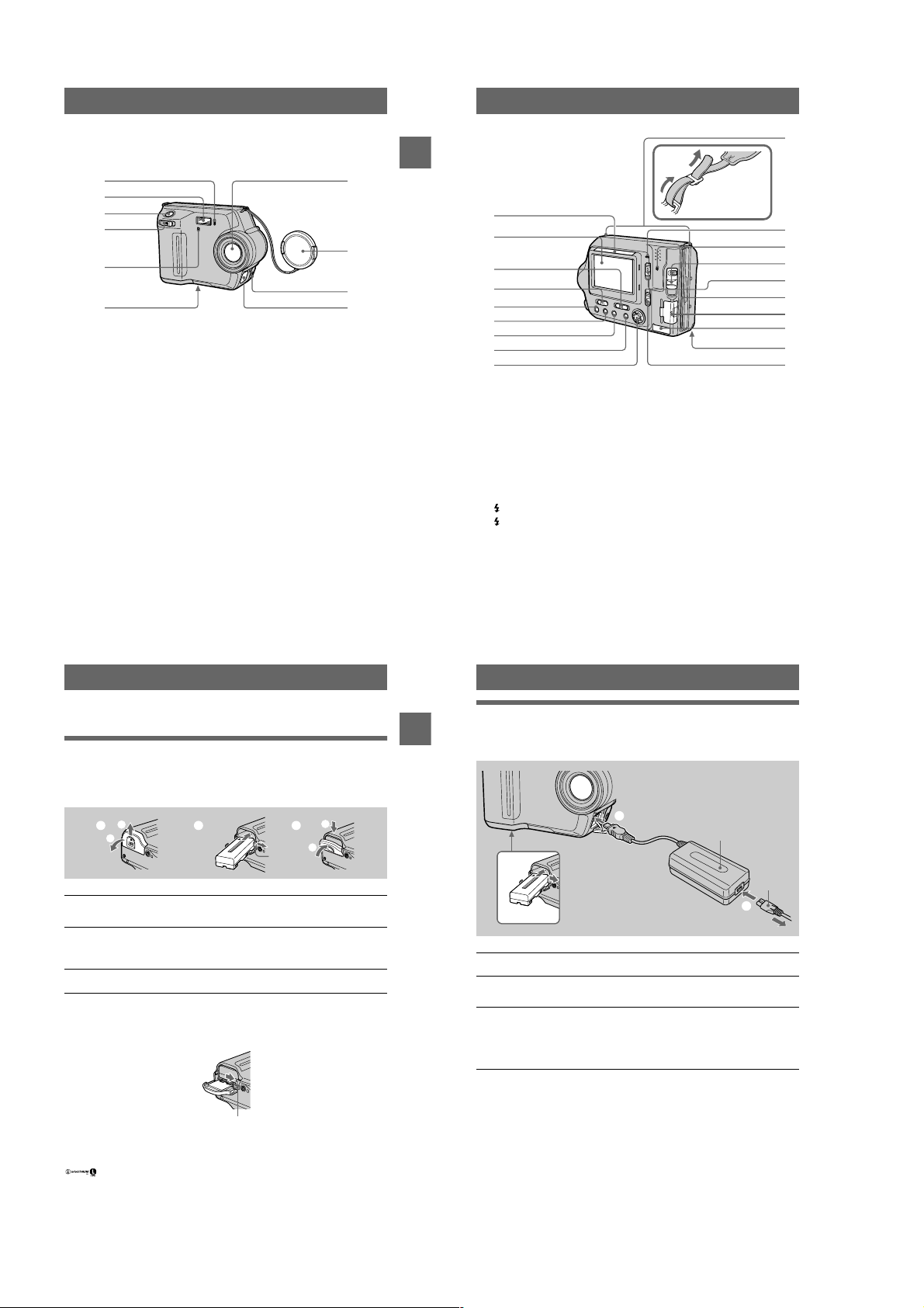
Identifying the parts
See the pages in parentheses for details of operation.
1
2
3
4
5
6
Self-timer lamp (21)
A
Flash (22)
B
Shutter button (18, 23)
C
Zoom lever (20)
D
Photocell window for flash
E
Do not block while recording.
Tripod receptacle (bottom
F
surface)
Use a tripod with a screw length of
less than 5.5 mm (7/32 inch). You
cannot firmly secure the camera to
tripods having longer screws, and
may damage the camera.
Lens
G
Lens cap (supplied)
H
VIDEO OUT jack (73)
I
DC IN cover/DC IN jack (10, 13)
J
7
8
9
0
w;
Getting started
Attaching the
shoulder strap
qa
qs
qd
qf
qg
qh
qj
qk
ql
Photocell window for LCD
K
screen
The LCD screen becomes brighter
when exposed to sunlight.
LCD screen
L
PLAY/STILL/MOVIEselector
M
(48)
LCD BACKLIGHT switch (20)
N
(Flash) button/
O
(Flash) lamp (22)
FOCUS button (64)
P
PROGRAM AE button (65)
Q
DISPLAY button (21)
R
Control button (48)
S
Hooks for strap
T
POWER ON/OFF (CHG)
U
(Charge) lamp (10)
Access lamp (18, 19)
V
DISK EJECT lever (16)
W
POWER switch (14)
X
Floppy disk slot (16)
Y
“Memory Stick” cover/
Z
“Memory Stick” slot (17)
USB cover/USB jack (29)
wj
Battery cover (9)
wk
MS /FD (“Memory Stick”/floppy
wl
disk) selector
wa
ws
wd
wf
wg
wh
wj
wk
wl
Preparing the power supply
Installing the battery pack
Your camera operates only with the NP-F330 (supplied)/F550 (optional)
“InfoLITHIUM” battery pack* (L series). See page 86 for more information about
“InfoLITHIUM” battery pack.
1
1 2 3
2
Battery
eject lever
Open the battery cover.
1
Slide the battery cover in the direction of the arrow.
Install the battery pack.
2
Press and hold the battery eject lever and then insert the battery pack with the
mark facing toward the battery compartment.
Close the battery cover.
3
To remove the battery pack
Open the battery cover.Slide the battery eject lever rightward, and remove the
battery pack.
Be careful not to drop the battery pack when removing it.
Battery eject lever
*
What is “InfoLITHIUM”?
“InfoLITHIUM” is a lithium ion battery pack whichcanexchange information such as battery
consumption with compatible video equipment. “InfoLITHIUM” L series battery packs have the
mark. “InfoLITHIUM” is a trademarkofSonyCorporation.
2
1
7
8
Charging the battery pack
When the camera is turned on, you cannot charge the battery pack. Be sure to turn off
Getting started
v
the power of the camera.
To DC IN jack
2
1
Battery pack
Insert the battery pack into your camera.
1
Open the DC IN cover and connect the AC power adaptor to the DC
2
IN jack of your camera with thevmark facing up.
Connect the power cord (mains lead) to the AC power adaptor and
3
then to a wall outlet (wall socket).
The POWER ON/OFF (CHG) lamp (orange) on the right of the LCD screen
lights up when charging begins. When the POWER ON/OFF (CHG) lamp goes
off, full charge is completed.
AC-L10A/L10B
AC power adaptor
To a wall outlet (wall socket)
3
Power cord
(mains lead)
After char ging the battery pack
Disconnect the AC power adaptor from the DC IN jack on your camera.
Battery remaining indicator
The LCD screen on the camera shows the remaining time for which you can still
record or play back images.
This indication may not be entirely accurate depending on the conditions of use and
the operating environment.
Werecommend charging the battery pack in an ambient temperature of between
10°Cto30°C(50°Fto86°F).
9
10
1-2
MVC-FD100/FD100H/FD200/FD200H
NP-F330 (supplied)/F550 (optional) battery pack
When you record images in an extremely cold location or using the LCD screen, the
operating time becomes short. When using the camera in an extremely cold location,
place the battery pack in your pocket or other place to keep it warm, then insert the
battery pack into the camera just before recording. When using a pocket heater, take
care not to let the heater directly contact the battery.
Auto power-off f unction
If you do not operate thecameraforaboutthreeminutesduringrecording,thecamera
turns off automatically to prevent wearing down the battery pack. To use the camera
again, slide the POWER switch down to turn on the camera again.
Note on t he POWER ON/OFF (CHG) lamp during charging
The POWER ON/OFF (CHG) lamp may flash:
• When a malfunction occurs in the battery pack.
The POWER ON/OFF (CHG) lamp does not light up:
• When the battery pack is not installed properly.
Charging time
Battery pack Full charge (min.)
NP-F330 (supplied) Approx. 150
NP-F550 Approx. 210
Approximate time to charge a completelydischarged battery pack at a temperature of
°C
(77°F).
25
Battery life and number of images that can be recorded/playedback
STILL mode recording/playback when using floppy disks
NP-F330 (supplied) NP-F550
Continuous
recording*
Continuous
playback**
Battery life
(min.)
Approx. 70 Approx. 750 Approx. 150 Approx. 1600
Approx. 80 Approx. 2200 Approx. 170 Approx. 4800
Number of
images
Battery life
(min.)
Number of
images
STILL mode recording/playback when using “Memory Stick”s
NP-F330 (supplied) NP-F550
Battery life
Getting started
Continuous
recording*
Continuous
playback**
Approximate battery life and number of images that can be recorded/played back at a
temperature of25°C(77°F) with a fully charged battery pack, 640×480 image size
and in NORMAL recording mode.
∗ Recording at about 5-second intervals when usingafloppydisk,oratabout 3-second intervals
when using a “Memory Stick”
∗∗Playing back single images continuously at about2-secondintervals
(min.)
Approx. 80 Approx. 1600 Approx. 170 Approx. 3400
Approx. 100 Approx. 3000 Approx. 230 Approx. 6900
Number of
images
Battery life
(min.)
Number of
images
MOVIE mode recording when using floppy disks
NP-F330 (supplied) NP-F550
Battery life (min.) Battery life (min.)
Continuous recording Approx. 85 Approx. 180
MOVIE mode recording when using “Memory Stick”s
NP-F330 (supplied) NP-F550
Battery life (min.) Battery life (min.)
Continuous recording Approx. 90 Approx. 190
Approximate time that can be recorded at a temperature of 25°C (77°F) and 160×112
image size with a fully charged battery pack.
Notes
• The battery life and numberof imageswillbedecreasedwhenu sing at low temperature, using
the flash, turning the power on/off frequently, or using the zoom.
• The capacity of the floppy diskorthe“MemoryStick”islimited.Theabove figures are as a
guide when you continuously record/play back by replacing the floppy disk or the “Memory
Stick.”
• If sufficient battery remaining time is indicatedbutthepowerruns out soon, fully charge the
battery so that the correct battery remaining time appears.
• Do not short the DC plug of the ACpower adaptor with a metallic object, as this may cause a
malfunction.
• Do not use the DC plug of the ACpoweradapter in a dirty state. Wipe offanydirtwithadry
cotton wool bud. Using the DC plug in a dirty state may prevent correct charging.
Using the AC power adaptor
1
To DC IN jack
Open the DC IN cover and connect the AC power adaptor to the DC
1
IN jack of your camera with the
Connect the power cord (mains lead) to the AC power adaptor and
2
then to a wall outlet (wall socket).
Using your camera abroad
For details, see page 85.
When using the AC power adaptor
Be sure to use it near a wall outlet (wall socket). If a malfunction occurs, disconnect
the plug from the wall outlet (wall socket).
v
AC-L10A/L10B
AC power adaptor
2
To a wall outlet (wall socket)
mark facing up.
Power cord
(mains lead)
11
12
Setting the date and time
When you first use your camera, set the date and time. If these are not set, the
Getting started
CLOCK SET screen appears whenever you turn on your camera.
POWER ON/OFF
(CHG) lamp
1
2 – 8
Control button
Press and hold thegreenbuttonand slide the POWER switch in the
1
directionofthearrowtoturnonpower.
The POWER ON/OFF (CHG) (green) lamp lights up.
Pressvon the control button.
2
The menu bar appears on the LCD screen.
EFFECT F ILE SETUP
SELECT OK
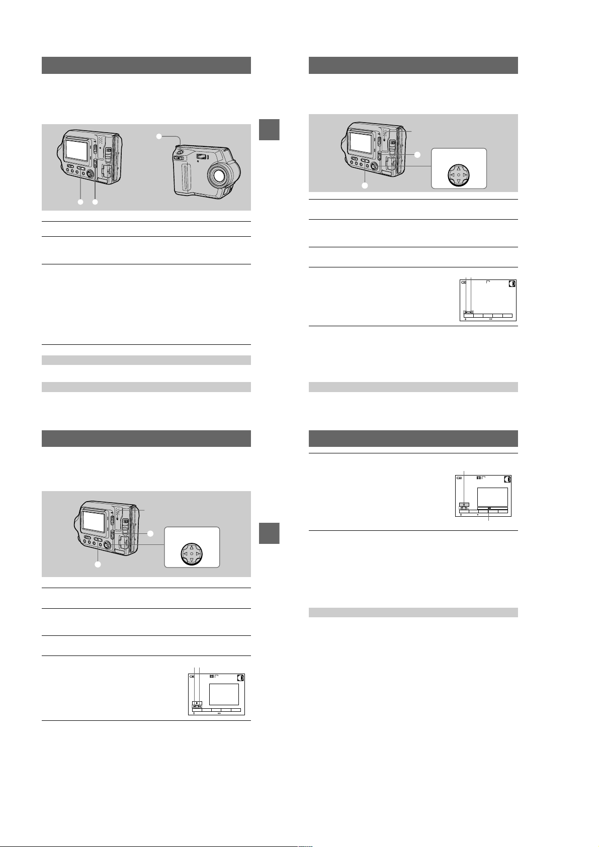
Select [SETUP]withBon the controlbutton,
3
then press the center
Select [CLOCK SET] withv/Von the control button, then press the
4
center
.
z
.
z
VIDEO OUT
CLOCK SET
BEEP
LCD BRIGHT
EFFECT F ILE SETUP
SELECT CLOSE
/LANGUAGE
CAMERA
MENU BAR OFF
CAMERA
13
1-3
14
VIDEO OUT
/LANGUAGE
CLOCK SET
BEEP
LCD BRIGHT
EFFECT F ILE SETUP
SELECT OK
200211
12:00:00A
CAMERA
CLOCK SET
M
2002 :/ / 1 1 12 00 AM
SELECT
Y/M/D
M/D/Y
D/M/Y
ENTER
CANCEL
OK
MVC-FD100/FD100H/FD200/FD200H
Select the desired date display format with
5
on the control button, then press the
v/V
center
.
z
Select from [Y/M/D] (year/month/day), [M/D/Y]
(month/day/year), or [D/M/Y] (day/month/year).
Select the year, month, day,hour or minute
6
item you want to set with
button.
The item to be set is indicated with
Set the numeric value withv/Von the
7
control button, then press the center
enter it.
After entering the number,
item. If you selected [D/M/Y] in step
time on a 24-hour cycle.
Select [ENTER] withBon the control button,
8
then press the centerzat the desired
moment to begin clock movement.
The date and time are entered.
on the control
b/B
v/V
moves to the next
v/V
.
5
,setthe
CLOCK SET
2002 : 1 1 12 00 AM//
OK
SELECT/ADJUST
CLOCK SET
2002 :/ / 1 1 12 00 AM
OK
SELECT/ADJUST
to
z
CLOCK SET
2002/ :/ 1 7 12 00AM
OK
SELECT/ADJUST
CLOCK SET
2002/ :/ 4 7 10 30PM
OK
SELECT
To cancel the date and time setting
Select [CANCEL] withv/V/b/Bon the control button, then press the centerz.
Y/M/D
M/D/Y
D/M/Y
ENTER
CANCEL
Y/M/D
M/D/Y
D/M/Y
ENTER
CANCEL
Y/M/D
M/D/Y
D/M/Y
ENTER
CANCEL
Y/M/D
M/D/Y
D/M/Y
ENTER
CANCEL
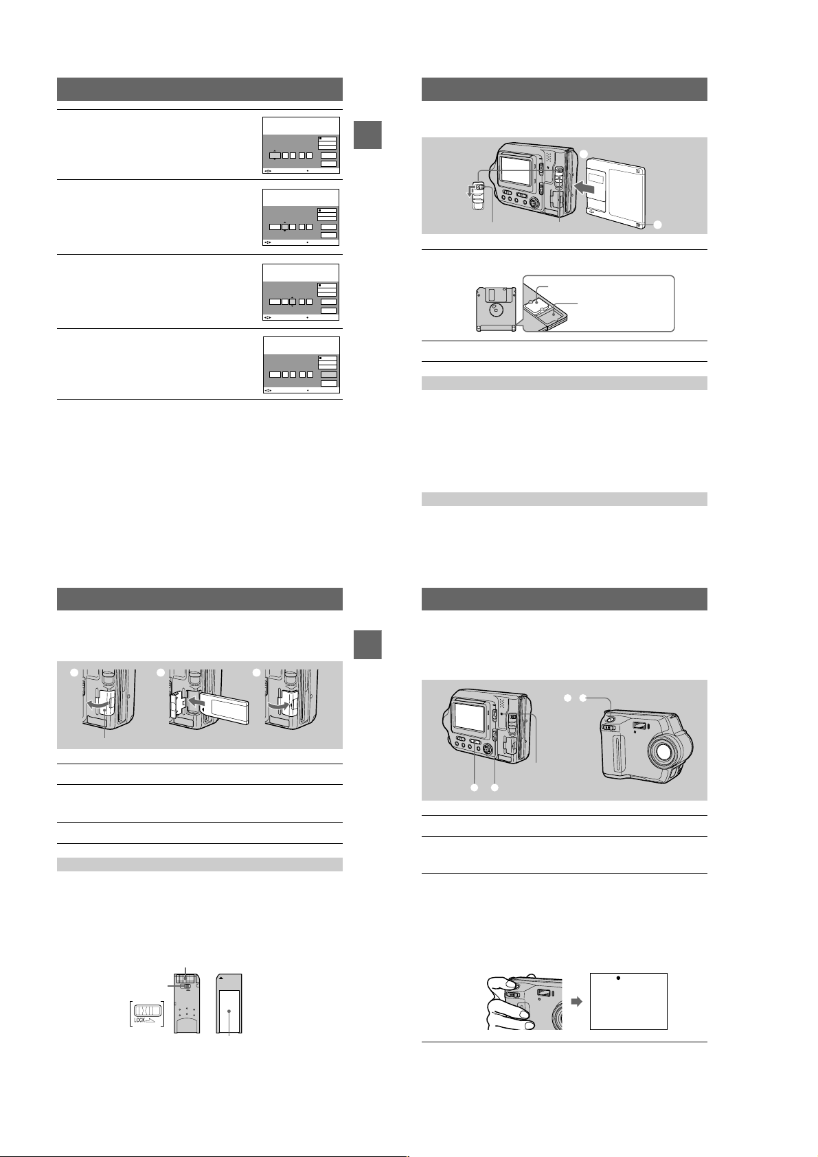
Inserting a floppy disk
Getting started
EJECT lock
Check that the write protect tab is set to the recordablepositionfor
1
recording.
Insert thefloppy disk until it clicks.
2
DISK EJECT lever
Usable floppy disks
• Size: 3.5-inch
• Type:2HD (1.44 MB)
• Format: MS-DOS format (512 bytes × 18 sectors)
Notes
• Do not insert the media otherthanthefloppydisks described above.
• You cannot use the optional MSAC-FD2M/FD2MA Floppy Disk Adaptor for Memory Stick.
• If the access lamp is lit, data is being read or written. Never remove the floppy disk, turn off
the power, or change the setting of the MS/FD selector while the access lamp is lit. Otherwise,
the image data could be damaged or lost.
Removingthefloppydisk
While sliding the EJECT lock to the left, slide down the DISK EJECT lever.
2
1
Recordable/erasable
Unrecordable/unerasable
Inserting a “Memory Stick”
See page 85 for details about “Memory Stick”.
1 2 3
“Memory Stick” cover
Open the “Memory Stick” cover.
1
Insert the “Memory Stick.”
2
Insert the “Memory Stick” with the
slot as illustrated until it clicks.
Close the “Memory Stick” cover.
3
Removing the “Memory Stick”
Open the “Memory Stick” cover, then push the “MemoryStick” once lightly.
Notes
• Insert the “Memory Stick” firmly until it clicks, otherwise a messagesuchas“MEMORY
STICK ERROR” will be displayed.
• If the access lamp is lit, data is being read or written. Never remove the “Memory Stick,” turn
off the power,orchangethesettingoftheMS/FD selector while the access lamp is lit.
Otherwise, the image data couldbe damagedorlost.
• You cannot record or edit imagesona“MemoryStick” if the write-protectswitchissettothe
LOCK position.
mark facing toward the “MemoryStick”
B
Connector
15
16
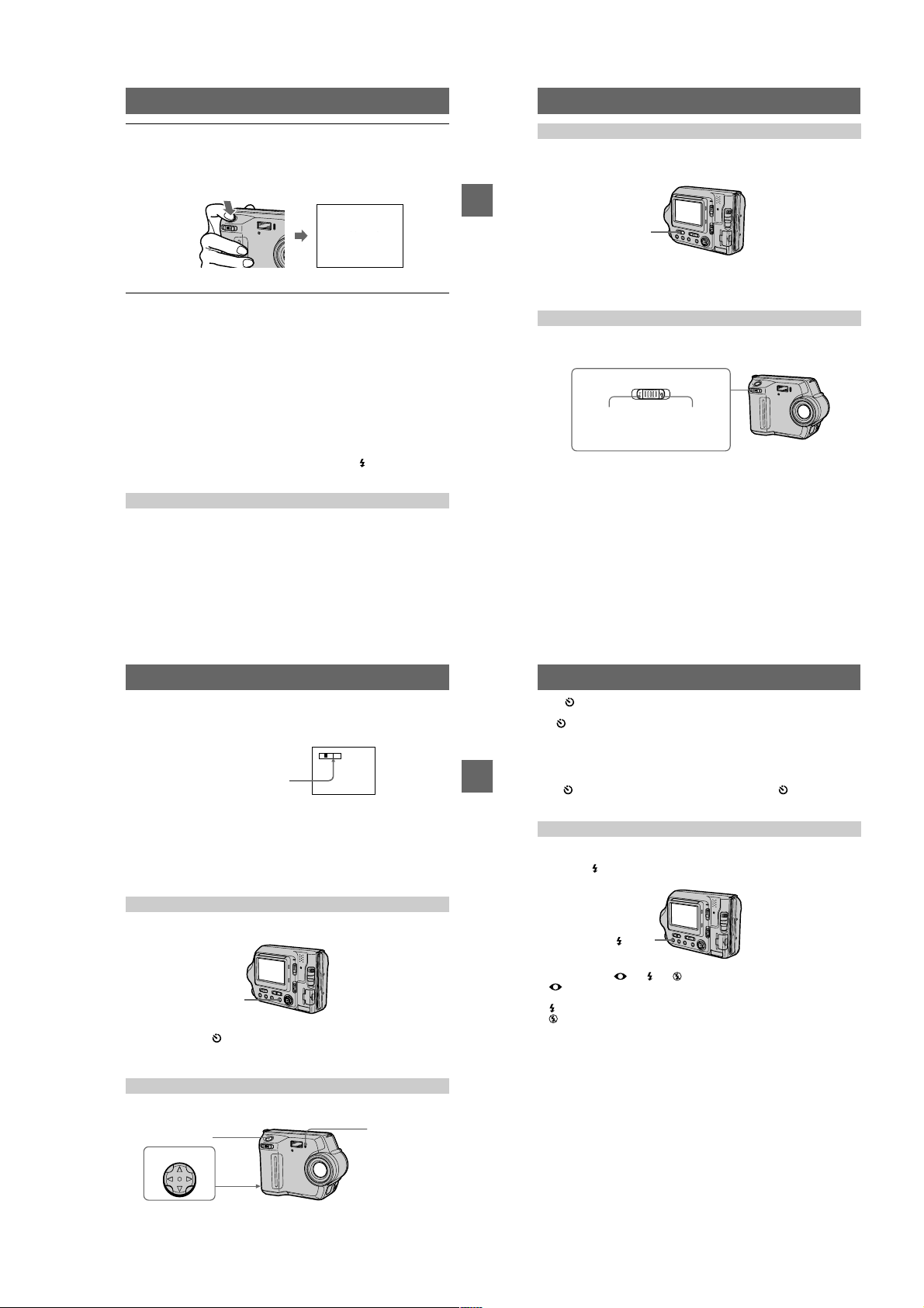
Basic operations
B Recording
Recording still images
Still images are recorded in JPEG format.
Getting started
Slide the POWER switch down to turn on the power and insert a floppy disk or a
“Memory Stick” in your camera.
3, 4
Access lamp
1 2
Set the PLAY/STILL/MOVIEselector to STILL.
1
Select the recording media using the MS/FD selector.
2
MS: Whenrecordingonthe“Memory Stick.”
FD: When recording on the floppy disk.
Press and hold the shutter button halfway down.
3
The image has not been recorded yet at this time. The camera automatically
adjusts the exposure and focus in accordance with the subject and recording
conditions. When the camera finishes the automatic adjustments, the AE/AF
lock indicator
and the camera is ready for recording.
If you release the shutter button, the recording will be canceled.
z stops flashing, then lights up and is followed by beeps,
AE/AF lock indicator (green)
flashes t lights up
Write-protect
switch
LOCK
Label space
The position and shape of thewrite-protect switch may differ depending on the types of
“Memory Stick” used.
17
18
1-4
MVC-FD100/FD100H/FD200/FD200H
Press the shutter button fully down.
4
The shutter clicks. “RECORDING” appears on the
will be recorded on the floppy disk or the “Memory Stick.” When
“RECORDING” disappears from the LCD screen, you can start the next
recording.
For the number of images you can record on a floppy disk or a
“Memory Stick”
Seepage58.
Notes
• When recording bright subjects, the color of the LCD screen may change after the
AE/AF is locked. However, this will not affect the recorded im age.
• While the image is being recorded on a floppy disk or a “Memory Stick,” the access
lamp lights. When this lamp is lit, do not shake or strike the camera. Also, do not
turn the power off, not change the position of the MS/FD selector, or not remove
the battery pack/floppydisk/“MemoryStick.”Otherwise,animagedatabreakdown
may occur and the floppy disk or the “Memory Stick” may become unusable.
• When you press the shutter button fully down at once, the camera starts recording
after the automatic adjustment is complete. However, the recording cannot be
carried out if the flash is required for the recording and the lamp (page 8) is
flashing.
Checking the last recorded image (Quick Review)
You can check the last recorded image by clearing the menu bar from the screen
(page 49) and p ressing
To return to the normal recording mode
Press the shutter button lightly, or select [RETURN] withb/Bon the control button
and then press the center
To delete the image
1 Select [DELETE] in the Quick Review screen using
and press the center
2 Select [OK] using
on the control button.
b
.
z
.
z
on the control button and press the centerz.
v/V
LCD screen, and the image
RECORDING
RECORDING
on the control button
b/B
BB
B Recording
B
Adjusting the brightness of the LCD screen
Adjust the brightness with the [LCD BRIGHT] item in the menu settings (page 56).
This adjustment does not affect the brightness of the images recorded on the floppy disk
or the “Memory Stick.”
LCD BACKLIGHT switch
To turn off the LCD backlight
Set the LCD BACKLIGHTswitch to OFF to save the battery.
Using the zoom feature
Zoom lever
T side: for
telephoto
(subject
appears closer)
W side: for wideangle (subject
appears farther
away)
If you cannot get a sharp focus on a close subject
Slide the zoom lever to the W side and move closer to the subject until the focus is
sharp (page 64).
Minimum focal distance to the subject
W side: About 25 cm (9 7/8 inches)
T side: About 80 cm (31 1/2 inches)
Torecord even closer subjects, see page 64.
Digital zoom function
This camera has a digital zoom function.
Digital zoom enlarges the image by digital processing, and it starts to function when
the zoom exceeds 3×.
T
W
The T-side of the bar shows the
digital zooming zone.
Using digital zoom
• The maximum zoom magnification is 6×.
• Digital zooming deteriorates the picture quality. When digital zoom is not
necessary, set [DIGITALZOOM] to [OFF] in the menu settings (page 54).
Note
Digital zoom does not work for moving images.
The indicators on the LCD screen during recording
Press DISPLAYto turn on/off the indicators on the LCD screen. See page 97 for a
detailed description of the indicators.
DISPLAY
Notes
• You cannot turn off the (self-timer) indicator and some of the indicators used inadvanced
operations.
• The indicators on the LCD screen are not recorded.
Using the self-timer
When you use the self-timer function, the subject is recorded approximately 10
seconds after you press the shutter button.
Shutter button
Control button
Self-timer lamp
19
BB
B Recording
B
20
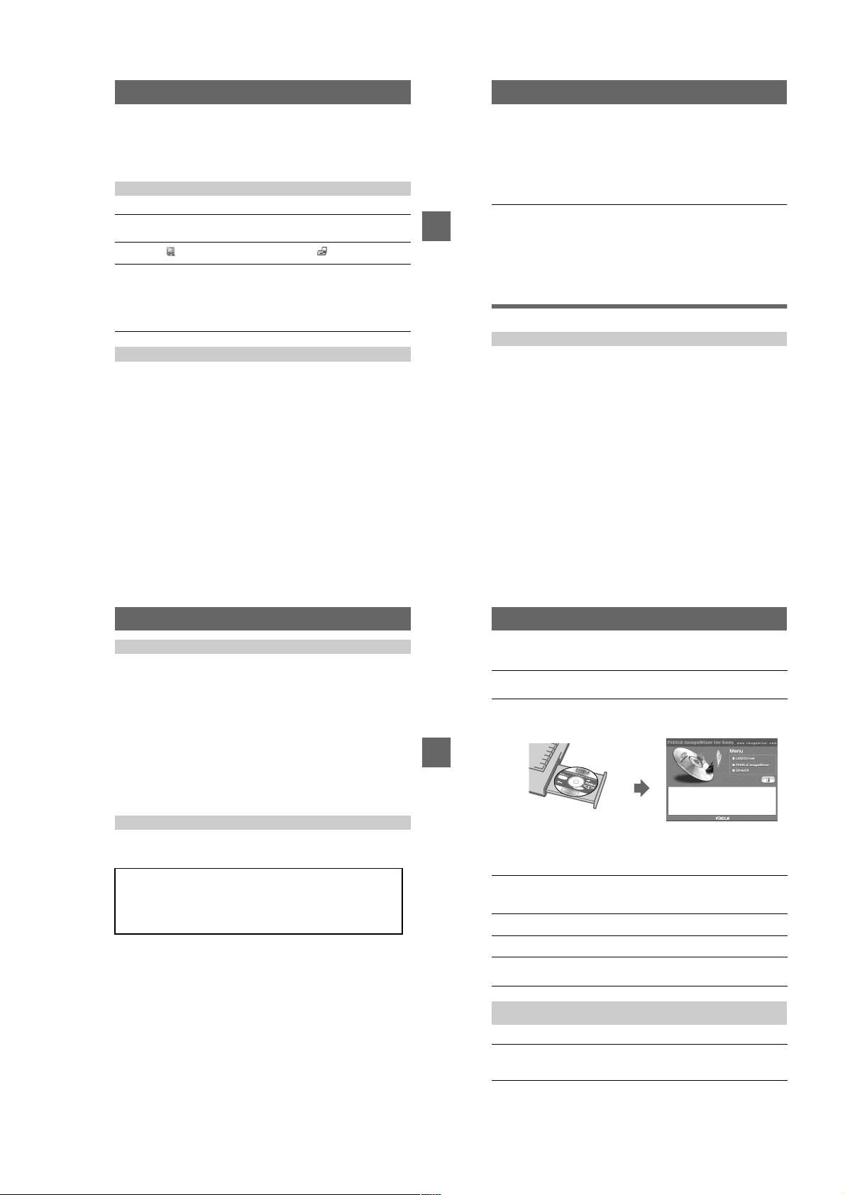
Select onthe LCD screen usingb/B/v/Von the control button and press the
.
center
z
The (self-timer) indicator appears on the LCD screen, and the subject is recorded
approximately 10 seconds after you press the shutter button. The self-timer lamp
flashes until the subject is recorded.
To cancel the self-timer
Tocancel the self-timer, pressvon the control button to display the menu bar and
select andpress the center
screen.
Recording images with the flash
The initial setting is AUTO (no indication). In this mode, the flash is automatically
activated when the surroundings are dark. To change the flash mode to other than
AUTO, press (Flash) several times until the desired flash mode indicator appears
on the LCD screen.
Each time you press the button, the indicator changes as follows.
(No indication)
eye phenomenon.
Youcanchange the amount of the flash light with [FLASH LEVEL] in the menu
settings (page 54).
Notes
• The recommended shooting distance of the built-in flash is 0.5 to 2.0 m (1 2/3 to 6 2/3 feet)
when [ISO] in the menu is [AUTO].
• Attachingaconversion lens(optional)mayblock the light from the flash andtheshadow of the
lens may be recorded.
• Auto red-eye reduction may not produce the desired red-eye reduction effects dependingon
individual differences,thedistance to the subject, if the subject does not see the pre-strobe, or
other conditions.
• The flash effectisnotobtainedeasilywhenyou use forced flash in a bright location.
tttt
Auto red-eye reduction : The flash strobes before recording to reduce the red-
Forced flash : The flash strobes regardless of the surrounding brightness.
No flash : The flash does not strobe.
on the control button to clear on the LCD
z
(Flash)
(No indication)
21
22
1-5
MVC-FD100/FD100H/FD200/FD200H
"b/B"
(playback)/
B Playback
Recording moving images
Moving images are recorded in MPEG format. Your camera does not record sound.
Slide the POWER switch d own to turn on the power and insert a floppy disk or a
“Memory Stick” in your camera.
3
1 2
Set the PLAY/STILL/MOVIEselector to MOVIE.
1
Select the recording media using the MS/FD selector.
2
MS: When recording on the “Memory Stick.”
FD: Whenrecordingonthefloppydisk.
Press the shutter button fully down.
3
“REC” appears on the LCD screen, and the moving image is recorded on the
floppydiskorthe“Memory Stick.”
If you press the shutter button momentarily
The image is recorded for 5 seconds. The recording time can be set to 10 or 15
seconds with [REC TIME SET] in the menu settings (page 53).
If you hold the shutter button down
The image is recorded while the shutter button is held down for up to 60
seconds. However,when [IMAGE SIZE] in the menu settings is set to
[320×240], the maximum recording time is 15 seconds (page 57).
Adjusting the brightness of the LCD screen, zoomingor using the self-timer
See pages 20 to 22.
LCD screen indicators during recording
Press DISPLAYto turn on/off the indicators on the LCD screen.
These indicators are not recorded. See page 97 for a detailed description of the indicators.
23
BB
B Recording
B
Playing back still images
Slide the POWER switch down to turn on the power and insert a floppy disk or a
“Memory Stick” in your camera.
Access lamp
3, 4
2
Control button
1
Set the PLAY/STILL/MOVIEselector to PLAY.
1
The last recorded image (still or moving) appears on the LCD screen.
Select the playback media using the MS/FD selector.
2
MS: When playing back images in the “Memory Stick.”
FD: When playing back images in the floppy disk.
Pressvon the control button to display the menu bar on the LCD
3
screen.
Select the desired still image with the
4
control button.
Press
"b/B"
: To display the preceding image.
"b
: To display the next image.
B"
on the control button to select
v/V/b/B
on the LCD screen, then pressb/B.
When the menu bar is not displayed
Youcandirectly select and play back the image withb/Bon the control button.
Notes
•
Youmight not be able to correctly play back images recorded with this camera on otherequipment.
• You may not be able to playbackimages whose image sizes are larger than the maximum
image size that can be used with this camera for recording.
LCD screen indicators during still image playback
Press DISPLAY to turn on/off the indicators on the LCD screen.
See page 98 for a detailed description of the indicators.
24
60min
640
DELETE
INDEX FILE SETUPTOOL
SELECT FILE BACK/NEXT
6/8
Playing back moving images
Slide the POWER switch down to turn on thepowerand insert a floppy disk or a
“Memory Stick” in your camera.
Access lamp
3 – 5
2
Control button
1
Set the PLAY/STILL/MOVIEselector to PLAY.
1
The last recorded image (still or moving) appears on the LCD screen.
Select the playback media using the MS/FD selector.
2
MS: When playing back images in the “Memory Stick.”
FD: When playing back images in the floppy disk.
Pressvon the control button to display the menu bar on the LCD
3
screen.
Select the desired moving image with the
4
control button.
Moving images are displayed one size smaller
than still images.
Press
"b/B"
: To display the preceding image.
"b
:Todisplaythenextimage.
B"
on the control button to select
v/V/b/B
on the LCD screen, then pressb/B.
"b/B"
60min
DELETE
INDEX FILE SETUPTOOL
SELECT
160
FILE BACK/NEXT
6/8
Select theB(playback) button on the
5
LCD screen with
button, then press the center
The moving image is played back.
During playback, B
(pause).
BB
B Playback
B
To pause playback
SelectX(pause) on the LCD screen withv/V/b/Bon the control button, then press
the center
.
z
on the control
v/V/b/B
.
z
(playback) changes to
X
B
X (pause) button
60min
160
DELETE
INDEX FILE SETUPTOOL
SELECT OK
Playback bar
6/8
0:05
When the menu bar is not displayed
Youcandirectly select the image withb/Bon the control button, and play back the
image by pressing the center
playback is paused.
. When you press the centerzduring playback,
z
LCD screen indicators during moving image playback
Press DISPLAY to turn on/off the indicators on the LCD screen.
See page 98 for a detailed description of the indicators.
25
26
1-6
MVC-FD100/FD100H/FD200/FD200H
Viewing images using a
computer
You can view or edit image data recorded with your camera using software installed
in your computer. You can also attach the image data to e-mail.
Viewingimagesusingafloppydiskdrive
Example: For Windows Me users
Turnon your computer and insert a floppy disk in the floppy disk
1
drive of your computer.
Open “ My Computer” and double-click “ 3 1/2 Floppy(A:).”
2
Double-clickafiletobeviewed.
3
See “Image file storage destinations andimage file names” (page 38) for
details.
It is recommended that you copy a moving image file to the hard disk of your
computer before viewing it. If you view the file directly from a floppy disk, the
image may break off.
ViewingimagesonacomputerusingtheUSBcable
This section describes the method for viewing imageson a computer using the
supplied USB cable.
The USB cable is used to connect the camera to a computer so that operations can
be performed on image files recorded in a floppy disk or a “Memory Stick” from the
computer.
In order to use the USB cable, a USB driver must be installed in the computer
beforehand.
Be sure to also refer to the operation manuals for your computer and the application
software.
ViewingimagesonWindows:page28
Viewing images on Macintosh: page 34
Notes on using your computer: page 37
Notes
• Data recorded with your camera is stored in the following formats.Makesurethatapplications
that support these file formats are installed on your computer.
—Still images (other than TEXT mode,uncompressed mode, and Clip Motion): JPEG format
—Moving images: MPEG format
—Uncompressed mode still images: TIFF format
—TEXT mode/Clip Motion: GIF format
• Depending on your application software, the file size may increase when you open a still image
file.
27
• When you copy an imageto thecamerafromyourcomputer, which was modified with
retouching software and wasconverted to another file format, the “FILE ERROR” message
may appear and you may be unabletoopen the image.
• Depending on your application software, only the first frame of the Clip Motionfilemaybe
played back.
Communications with your computer (for Windows only)
Communications between your camera and your computer may not recover after
recovering from Suspend or Sleep.
• Microsoft, Windows and Windows Media are either registered trademarks or trademarks of
Microsoft Corporation in the United Statesand/orothercountries.
• Macintosh, Mac OS and QuickTime are either registeredtrademarks or trademarks of Apple
BB
B Playback
B
Computer, Inc.
• All other product names mentioned herein may be the trademarks or registered trademarks of
their respective companies. Furthermore, “™” and “®” are not mentioned in each case in this
manual.
• In this manual, the Windows2000Professional is referred to as “Windows 2000”,and
WindowsMillennium Editionisreferred to as“Windows Me”,andWindows XP HomeEdition
and WindowsXPProfessional are referred to as “Windows XP.”
Viewing images on Windows
Recommended computer environment
OS: Microsoft Windows98, Windows98SE, Windows2000Professional,
Windows Millennium Edition, Windows XP Home Edition, WindowsXP
Professional
The above OS must be installed at the factory.
Operation is not assured in an environment upgraded to the operating systems
described above.
CPU: MMX Pentium 200 MHz or faster
The USB connector must be provided as standard.
Windows Media Player (recommended) must be installed to play back moving
pictures.
Notes
• IfyouconnecttwoormoredevicesthatuseUSBtoasinglecomputeroruseahub,operationis
not guaranteed.
• Some USB devicesmaynotoperateifthey are connected to the computer at the sametimeas
your camera.
• Operations are not guaranteed for alltherecommended computer environments mentioned
above.
28
General procedure for viewing images
Installing the USB driver to the computer (page 29)
Step 1
Perform this step only when you view images on your computer for the
first time.
Connecting your camera to your computer using the USB cable
Step 2
(page 30)
ViewingimagesonWindows(page32)
Step 3
For Windows XP users
You do not have to install a USB driver.Windows XP recognizes the camera as a
drive as soon as it is connected it to the computer using the USB cable. Begin the
procedure from Step 2.
The operation below is explained using Windows Me. The window screen and
operation method may be different depending on the type of OS.
Step 1 Installing the USB driver to the computer
Before connecting your camera to your computer, install the USB driver to the
computer. The USB driver is included with the application software in the CD-ROM
which is supplied with your camera.
For Windows 98, Windows 98SE, Windows 2000, and Windows Me
users
Do not connect your camera to your computer yet. Be sure to
complete installation of the USB driver before connecting your
camera to the computer. If you connect the USB cable first, you will
be unable to install the USB driver properly.
See “If the Removable Disk does not appear” (page 33) for corrective measures if the
USB cable was connected before installing the driver and the driver software could
not be installed correctly.
Before operation
If you are using Windows 2000, log in as an administrator and then install the USB
driver.
Turnon your computer and allow Windows to load.
1
Close all applications you are running on your computer.
Insert the supplied CD-ROM in the CD-ROM drive of your
2
computer.
The title screen appears after a moment.
BB
B Playback
B
If the title screen does not appear
Double-click “My Computer” on the Desktop.
1
Double-click the CD-ROM (“ImageMixer (E:)*”).
2
∗ The drive symbol ((E:), etc.) may differ depending on your computer.
Click “USB Driver” on the screen.
3
The “Welcome to the InstallShield Wizard for Sony USB Driver” window
appears.
Follow the on-screen messages to install the USB driver.
4
Eject the CD-ROM from the computer.
5
Select “Yes, I want to restart my computer now” and click “Finish.”
6
Your computer restarts and you can connect your camera to your computer.
Step 2 Connecting your camera to your computer using the USB
cable
Youcanconnect your camera to your computer after Windows is loaded.
Insertafloppydiskora“Memory Stick” in your computer and set
1
the MS/FD selector in accordance with the media you have
inserted.
29
30
1-7
MVC-FD100/FD100H/FD200/FD200H
Connect the AC power adaptor to your camera and turn on your
2
camera.
Use the supplied dedicated USB cable to connect the USB jack
3
(mini-B) on your camera to the USB connector on your computer.
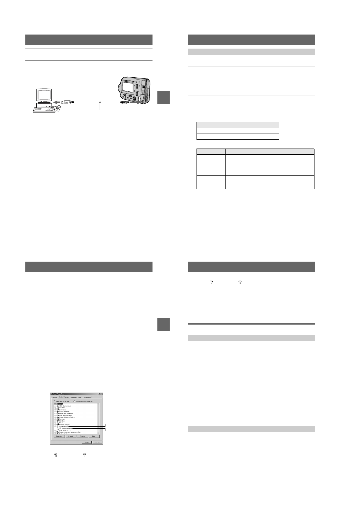
Computer
To the USB
connector
“USB MODE” appears on the LCD screen of your camera.
When you connect the camera for the first time, the operation automatically
starts to allow your computer to recognize the camera. Be sure to wait until the
operation finishes.
See “If the Copy Wizard appears” (page 33) if you are using WindowsXP.
Cautions
• If you connect your camera to a computer with two or more USB jacks,donotconnect
any other USB device excepting a keyboard and/or mouse.
• If you have a desktop computer, use the USB jack ontherearpanel of the computer.
When you disconnect the USB cable from your computer,
when you remove a floppy disk or a “Memory Stick” from the
camera being connected to the computer using the USB
cable, and when you switch the MS/FD selector
For Windows 2000, Windows Me, and Windows XP users
Double-click the “Remove hardware” icon displayed at the lower
1
right of the desktop screen.
Click “Sony DSC” and click “Stop.”
2
Confirm the drive to be removed and click “OK.”
3
Click “OK.”
4
Perform operations such as disconnecting the USB cable.
5
For Windows 98 and Windows 98SE users
Perform only step 5 above.
USB cable (supplied)
To the USB jack
Push the connector in
as far as it will go.
31
Step 3 Viewing images on Windows
Youcanview the images recorded in your camera while the camera is connected to
your computer.
Open “My Computer” on Windows and double-click the newly
1
recognized drive “Removable Disk” (E:)*.
The folder in a floppy disk or a “Memory Stick” is displayed.
If “Removable Disk” is not displayed, see “If the Removable Disk does not
appear” (page 33).
∗ The drive symbol ((E:), etc.) may differ depending on your computer.
Select an image file to be viewed from the folder and double-click
2
BB
B Playback
B
the file.
See “Image file storage destinations and image file names” (page 38) for
further information.
Viewing an image of a floppy disk
Desired file type
E-mail image “E-mail” foldertImage file
Other files Image file
Viewing an image of a “Memory Stick”
Desired file type
Still image “Dcim” foldert“100msdcf” foldertImage file
Moving image* “Mssony” folder
Clip Motion
image
E-mail image
TIFF image
(uncompressed)
∗ Copying a file to the hard diskofyourcomputer before viewing it is recommended. If
you view thefiledirectly from a floppy diskora“MemoryStick,”theimagemaybreak
off.
Double-click in this order
Double-click in this order
t
“Dcim” folder
“Mssony” folder
t
t
“
Moml0001
“
100msdcf
“
Imcif100
” foldertImage file*
” foldertImage file
” foldertImage file
To copy the image data to your computer
Open a folder that contains the image data to be copied, and drag and drop the image
data to the “My Documents” (example) folder.
Caution
If you copy an image with the same filename to the same folder in your computer, a
confirmation message for overwriting the original image data will appear. If you
want to delete the original image and copy an image you want to drag and drop, click
“Yes .” If you want to keep the original image, click “No” and change the filename of
the image you want to drag and drop.
32
If the Copy Wizard appears (for Windows XP users)
Use the following procedure to copy an image data from your camera to your
computer.
Click “Copy pictures to a folder on my computer using Microsoft
1
Scanner and Camera Wizard,” andthenclick“OK.”
Follow the instructions displayed on the screen to copy an image.
2
Select “My Documents” (example) as the copy destination.
Tocopy another image, click “Finish”, disconnect the USB cable, and connect it
again. Then, repeat the procedure in the Copy Wizard screen.
If the Removable Disk does not appear
Delete a driver registered unintentionally while your camera is connected to your
computer. See “Step 2 Connecting your camera to your computer using the USB
cable (page 30)” for the connecting method. Perform all steps below to install the
USB driver properly.
Open “Device Manager” on your computer.
1
For Windows 2000 users:
Select “My Computer”
andthenclick“Device Manager.”
For Windows 98, Windows 98SE, Windows Me users:
Select “My Computer”
Manager.”
Check whether a USB driver is already installed.
2
1 Click “Other Devices.”
Check for “ Sony DSC” or “ Sony Handycam” with a question mark.
2
“Control Panel”t“System” open “Hardware” tab,
t
“Control Panel”t“System” and click “Device
t
1
2
3
If there is a device indicated with a question mark, delete it.
Click “ Sony DSC” or “ Sony Handycam”.
1
Click “Remove.” The “Confirm Device Removal” screen appears.
2
Click the “OK” button.
3
4
Turn off your camera and disconnect the dedicated USB cable from
the camera and computer.
5
Install the USB driver provided on the supplied CD-ROM.
See “Step 1 Installing the USB driver to the computer (page 29).”
BB
B Playback
B
Viewing images on Macintosh
Recommended Computer environment
OS: Mac OS 8.5.1/8.6/9.0/9.1/9.2, Mac OS X(v10.0/v10.1)
The above OS must be installed at the factory.
However,note that the upgrade to Mac OS 9.0/9.1 should be used for the
following models.
— iMac with the Mac OS 8.6 factory pre-installed and a slot loading type
CD-ROM drive
— iBook or Power Mac G4 with the Mac OS 8.6 factory pre-installed
Mac OS X(v10.0/v10.1) users can use a USB connection only when a
“Memory Stick” is used.
The USB connector must be provided as standard.
QuickTime 3.0 or newer must be installed to play back moving pictures.
Notes
• IfyouconnecttwoormoredevicesthatuseUSBtoasinglecomputeroruseahub,operationis
not guaranteed.
• Some USB devicesmaynotoperateifthey are connected to the computer at the sametime as
your camera.
• Operations are not guaranteed for alltherecommended computer environments mentioned
above.
General procedure for viewing images
Installing the USBdriver to the computer (page 35)
Step 1
Perform this step only when you view the images on your computer for
the first time.
Connecting your camerato your computer using the USB cable
Step 2
(page 36)
ViewingimagesonMacintosh(page36)
Step 3
33
34
1-8
MVC-FD100/FD100H/FD200/FD200H
For Mac OS 9.1/9.2 Mac OS X(v10.0/v10.1) users
You do not have to install a USB driver. Macintosh recognizes the camera as a drive
as soon as it is connected it to the Macintosh using the USB cable. Begin the
procedure from Step 2.
Step 1 Installing the USB driver to the computer
Before connecting your camera to your computer, install the USB driver to the
computer. The USB driver is included with the application software in the CD-ROM
which is supplied with your camera.
Turn on your computer and allow the Mac OS to load.
1
Insert the supplied CD-ROM in the CD-ROM drive of your
2
computer.
The CD-ROM window (Pixela ImageMixer) appears.
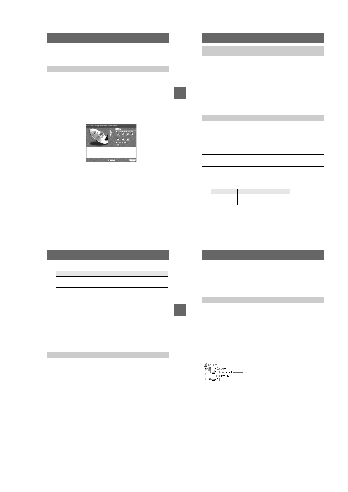
Double-click the “SetupMenu” icon in the CD-ROM window.
3
The “PIXELA ImageMixer for Sony” appears.
Click “USB Driver” button (folder button).
4
The folder containing the six Sony USB driver related files opens.
Select the following two files and drag and drop them to the
5
system folder. When the message is displayed, click “OK.”
• Sony USB Driver
• Sony USB Shim
Restart your computer.
6
Step 2 Connecting your camera to your computer using the USB
cable
See page 30 for the procedure to connect your camera to your computer using the
USB cable.
When you disconnect the USB cable from your computer,
when you remove a floppy disk or a “Memory Stick” from the
camera being connected to the computer using the USB
cable, and when you switch the MS/FD selector
Draganddropthefloppydiskorthe“Memory Stick” icon into the recycle bin and
then perform operations such as disconnecting the USB cable.
BB
B Playback
B
For Mac OS X(v10.0) users
Turn off your computer first and then perform operations such as disconnecting t he
USB cable.
Step 3 Viewing images on Macintosh
Youcanview the images recorded in your camera while the camera is connected to
your computer.
For Mac OS X(v10.0/v10.1) users
Youcanuse only a “Memory Stick” with a computer running Mac OS X(v10.0/
v10.1). Even if you insert a floppy disk,MacOSX(v10.0/v10.1)cannotrecognizeit.
Touse data saved on a floppy disk, copy it to a “Memory Stick” first (page 77).
Double-click the newly recognized icon on the desktop.
1
The folders in a floppy disk or a “Memory Stick” are displayed.
Select and double-click the desired image file from the folder.
2
See “Image file storage destinations and image file names” (page 38) for
further information.
Viewing an image of a floppy disk
Desired file type
E-mail image “E-mail” foldertImage file
Other files Image file
Double-click in this order
Viewing an image of a “Memory Stick”
Desired file type
Still image “Dcim” foldert“100msdcf” foldertImage file
Moving image* “Mssony” folder
Clip Motion
image
E-mail image
TIFF image
(uncompressed)
∗ Copying a file to the hard diskofyourcomputer before viewing it is recommended. If
you view thefiledirectly from a floppy diskora“MemoryStick,” the image may break
off.
“Dcim” folder
“Mssony” folder
Double-click in this order
“
Moml0001
“
100msdcf
“
Imcif100
” foldertImage file
” foldertImage file*
” foldertImage file
t
t
t
To copy image data to your computer
Open the folder that contains an image data you want to copy,and drag and drop the
image data to the hard disk icon.
The image file is copied to the hard disk.
Notes on using your computer
Floppy disk and “Memory Stick”
• Be sure to format a floppy disk and a “Memory Stick”usingyourcamera(page81).
Youcannotformat a floppy disk or a “Memory Stick” from a computer connected
using the USB cable.
• Use the DOS/V format 2HD type floppy disk. A computer cannot correctly
recognize a floppy disk other than this type.
• Do not compress the data on the “Memory Stick.” Compressed files cannot be
played back on your camera.
35
36
Image file storage destinations
and image file names
Image files recorded with your camera are grouped in folders by recording mode.
Images in a floppy disk and ones in a “Memory Stick” have different file names. The
meanings of the file names are as follows.
When using floppy disks
stands for any number within the range from 001 to 999.
sss
stands for one of the following characters below.
BB
B Playback
B
f
S: Still image file recorded at 640×480 size
F:Stillimagefileofmorethan640×480 size
V:Moving image file recorded at 160×112 size
W:Moving image file recorded at 320×240 size
T: Still image file recorded in TEXT mode
C: Clip Motion file recorded in NORMAL mode
M:Clip Motion file recorded in MOBILE mode
For Windows Me users (The drive recognizing the floppy disk
is [A:].)
Storage destination containing still image,
moving image, TEXT mode image and Clip
Motion image data
Folder containing E-MAIL mode image data
37
38
1-9
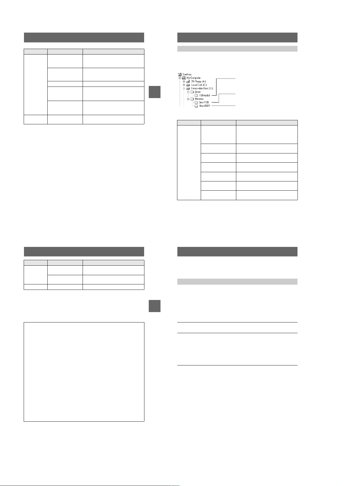
MVC-FD100/FD100H/FD200/FD200H
Location File Meaning
3 1/2 Floppy
[A:]
E-MAIL
folder
• The numerical portions of the following files are the same.
— An image file recorded in E-MAIL mode and its corresponding small-size
image file
— An image file recorded in TEXT mode and its corresponding index image file
— An image file recorded with Clip Motion and its corresponding index image file
• INDEX display files recorded in the TEXT mode or Clip Motion mode are played
back only on t his camera.
MVC-
MVC-
MVCMVC-
MVC-
MVC-
.JPG • Still image file recorded normally
sssf
sssf
sssf
sssf
sssf
sss
• Still image file recorded in E-MAIL
mode (page 61)
.411 • INDEX display file
Thisfilecanonlybeplayedbackon
your camera.
.MPG • Moving image file
.GIF • Still image file recorded in
— TEXT mode (page 62)
— Clip Motion (page 59)
.THM • Index image file recorded in
— TEXT mode (page 62)
E.JPG • Small-size image file recorded in
— Clip Motion (page 59)
E-MAIL mode (page 61)
When using “Memory Stick”s
stands for any number within the range from 0001 to 9999.
ssss
For Windows Me users (The drive recognizing the camera is
[D:])
Folder containing still image recorded in
normal mode, TEXT mode image and Clip
Motion image data
Folder containing E-MAIL mode and TIFF
BB
B Playback
B
mode image data
Folder containing moving image data
Folder File Meaning
100msdcf DSC0
CLP0
CLP0
MBL0
MBL0
TXT0
TXT0
.JPG • Still image file recorded normally
ssss
ssss
ssss
ssss
ssss
ssss
ssss
• Still image file recorded in
— E-MAIL mode (page 61)
— TIFF mode (page 63)
.GIF • Clip Motion file recorded in NORMAL
mode (page 59)
.THM • Index image file of Clip Motion file
recorded in NORMAL mode
.GIF • Clip Motion file recorded in MOBILE
mode (page 59)
.THM • Index image file of Clip Motion file
recorded in MOBILE mode
.GIF • Still image file recorded in TEXT mode
(page 62)
.THM • Index image file of still image file
recorded in TEXT mode
Folder File Meaning
Imcif100 DSC0
DSC0
Moml0001 MOV0
The numerical portions of the following files are the same.
— A small-size image file recorded in E-MAIL mode and its corresponding image
file
— An uncompressed image file recorded in TIFF mode and its corresponding
image file
— An image file recorded in TEXT mode and its corresponding index image file
— An image file recorded with Clip Motion and its corresponding index image file
Tips
The digital still camera saves recorded images as digital data. The format of the
saved data is called as the file format. The formats that can be used with this
camera are as follows:
JPEG format
Most digital still cameras, operating systems of computers, and browser
software adopt this format. This format is able to compress files without
appreciable deterioration. However, if the image is compressed and saved on
repeated occasions, the image will deteriorate. This camera records still images
using the JPEG format for normal recording.
GIF format
Using this format, the image will not deteriorate eveniftheimageiscompressed
and saved on repeated occasions. This format limits the number of colors used
to 256 colors. This camera records still images using the GIF format in Clip
Motion (page 59) or TEXT mode (page 62).
TIFF format
Stores shooting images without compression, so the image does not deteriorate.
Most of operating systems and applications correspond to this format. This
camera records still images using the TIFF format for the TIFF mode (page 63).
MPEG format
This format is very typical for moving images. This camera records moving
images in the MPEG format during the recording.
.JPG • Small-size image file recorded in
ssss
ssss
ssss
E-MAIL mode (page 61)
.TIF • Uncompressed image file recorded in
TIFF mode (page 63)
.MPG • Moving image file recorded normally
39
40
Viewing images using
“ImageMixer”
Installing “PIXELA ImageMixer Ver.1.0 for Sony”
Youcaneasily view a still image and/or moving image recorded by your camera
using the “PIXELA ImageMixer Ver.1.0 for Sony” provided on the CD-ROM
supplied with your camera.
The system requirements of your computer are indicated in the operation manual
supplied with the CD-ROM.
BB
B Playback
B
Before operation
If you are using Windows 2000 and WindowsXP, log in as an administrator and then
install the USB driver.
Turnon your computer.
1
Close all applications you are running on your computer.
Insert the supplied CD-ROM in the CD-ROM drive of your
2
computer.
The title screen appears after a moment.
If the title screen does not appear
Double-click “My Computer” on the Desktop.
1
Double-click the CD-ROM (“ImageMixer (E:)*).
2
∗ The drive symbol ((E:), etc.) may differ depending on your computer.
Select “PIXELA ImageMixer Ver.1.0 for Sony” in the title screen.
3
For Windows users
1
Click “PIXELA ImageMixer” and install the software in
accordance with the instructions displayed on the screen.
After confirming the information in the “Readme.txt” screen displayed at
the end of installing process, close this screen and click “Finish.”
IfyouareusingWindowsXP,skipsteps2to4below. Goto
.
4
step
2
Click “DirectX” in the title screen.
The “Microsoft DirectX8.0 Setup” screen appears.
3
Click “Yes.”
The “DirectX(R) Setup” screen appears.
4
Click “Install.”
The installation starts. When the installation finishes, click “OK” and
restart your computer.
41
42
1-10
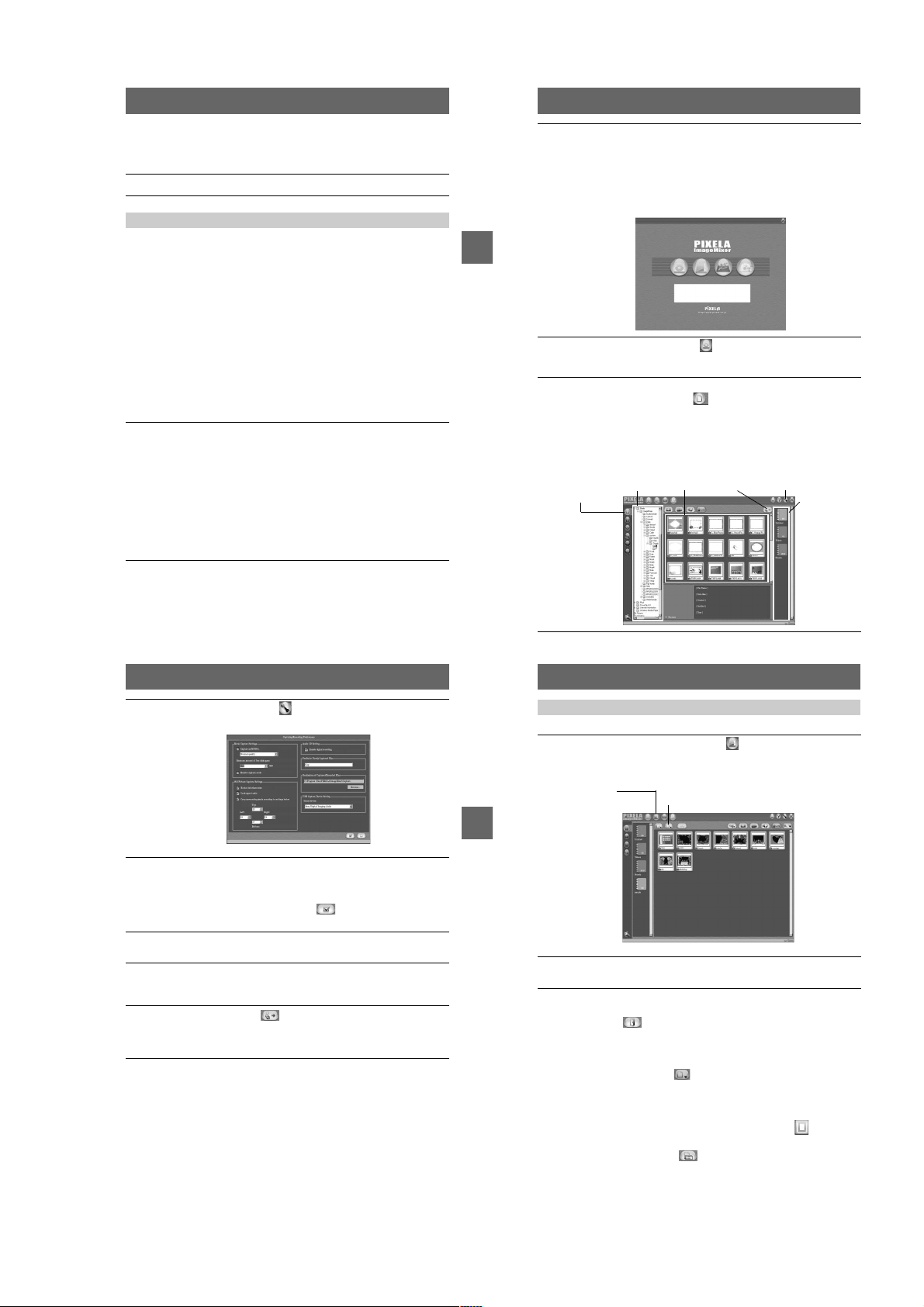
MVC-FD100/FD100H/FD200/FD200H
For Macintosh users
Click the button of the language (such as English) of the version to be installed
in the title screen and then install the software in accordance with the
instructions displayed in the screen.
Remove the CD-ROM from the computer.
4
Tocopy image data to your computer using “ImageMixer”
Use the following procedure o f “PIXELA ImageMixer” to copy a still image or
moving image data recorded in your camera.
The procedure below is explained using screens displayed by Windows. Youcan
copy the image using a similar procedure for Macintosh also.
For Mac OS X(v10.0/v10.1) users
Y oucan use only a “Memory Stick” with a computer running Mac OS X(v10.0/
v10.1). Even if you insert a floppy disk, MacOSX(v10.0/v10.1)cannotrecognizeit.
Touse data saved on a floppy disk, copy it to a “Memory Stick” first (page 77).
Cautions
• Sometimes an displayed image may be interrupted when you view it on your computer using
the USB cable.
• The screen display of your camera isnotcopied to your computer.
If you encounter a trouble
Close “ImageMixer” and restart it to retry.
Prepare your camera and computer.
1
Turnon your computer.
1
Insert a floppy disk or a “MemoryStick” in your computer and
2
set the MS/FD selector in accordance with the media you have
inserted.
Connect the AC power adaptor to your camera and turn on your
3
camera.
Connect your camera to your computer using the USB cable.
4
“USB MODE” appears on the LCD screen of your camera.
Start “ImageMixer” on your computer.
2
For Windows users
Open the nested windows in the following order: “Start”t“Program”
“Pixela”t“ImageMixer”t“PIXELA ImageMixer Ver.1.0for Sony”.
For Macintosh users
Click “PIXELA ImageMixer Ver.1.0for Sony” in the installed folder.
“ImageMixer” starts and the main screen is displayed.
BB
B Playback
B
Click the Capture Environment displayed on the left edge of the
3
screen.
The screen for copying an image is displayed.
Select a folder that contains an image to be copied.
4
Click the Import File Mode button displayed on the left of the screen and
select a folder that contains an image to be viewed from the folder list window.
A list of the images stored in the selected folder is displayed in the file
thumbnail list window.
If the image is stored in a floppy disk or a “Memory Stick” set in your camera,
select “Removable Disk (E:)*”.
∗ The drive symbol ((E:), etc.) may differ depending on your computer.
Import
File Mode
button
Folder list
window
Thumbnail list
window
Capture
button
Preferences
button
Album list
window
t
Click the Preferences button at the top right of the screen.
5
The “Capturing/Recording Preferences” screen appears.
Select a folder in which the copied image is stored.
6
Click “Browse” for “Destination of Captured/Recorded Fi les”and click “My
Documents” (example) in the “Browse for Folder” screen that is displayed.
Then, click “OK.”
After you finish the setting, click the button at the bottom right of the
screen.
Click an album in the album list window.
7
Select an album in which you want to save a file.
Click to select an image to be copied to your computer.
8
Youcanselect two or more images by clicking the images while holding down
the Control key for Windows (Option key for Macintosh).
Click the Capture button at the upper right of the screen.
9
The image is copied to your computer.
Youcanalso copy the image by dragging and dropping it from the file
thumbnail list window to the album.
43
44
Viewing images using “ImageMixer”
Youcanuse “ImageMixer” to view the image copied to your computer.
Click the Album Environment button in the main screen or
1
image copy screen.
Select an album that contains an image you want to view.
The screen for viewing images appears.
Album
Environment
button
BB
B Playback
B
Double-click the image to be viewed.
2
The selected image is displayed.
To return to the image list display screen
Click the close button displayedon the upper right of the screen.
To print the image
1
Click an image to be printed in the imagelist display screen.
2
Click the File Menu button and click “Print” on the displayed
menu.
The “Print Layout Settings” screen appears.
3
Set the layout.
Set the layout you prefer. Normally, click the Print Image Only button under
the screen.
4
Click the print setup button at the lower right of the screen.
The “Print Setup” screen appears. Set the paper size and printing direction and
click “OK.”
File Menu
button
45
46
1-11
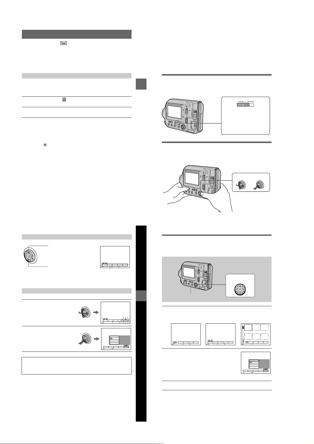
MVC-FD100/FD100H/FD200/FD200H
Click the print button at the lower right of the screen.
5
The “Print” screen appears. Click “OK.”
The image is printed.
If the image is not printed
Confirm whether the printer setting is correct.
See the operating instructions supplied with your printer for further information.
Viewingtheon-linehelpof“PIXELA ImageMixer Ver.1.0 for Sony”
You can find detailed information about procedures and functions of “PIXELA
ImageMixer Ver.1.0 for Sony.”
For Windows users
Click the Help button at the upper right of the screen.
1
The “ImageMixer Help” screen appears.
Youcan access the information you want from the table of
2
contents or click a link displayed in blue characters (site address).
For Macintosh users
Use your web browser to open the manual.html file in the folder in which
ImageMixer Ver.1.0 for Sony is installed.
To close the on-line help
Click the button for closing the window of “PIXELA ImageMixer Ver.1.0 for
Sony”
If you have any questions about “PIXELA ImageMixer Ver.1.0
for Sony”
ImageMixer Ver.1.0 for Sony is a trademark of PIXELA corporation.
Refer to the information web site at: “http://www.imagemixer.com”.
Advanced operations
Before performing advanced
operations
This section describes the basic control methods that are frequently used for
“Advancedoperations.”
How to use the PLAY/STILL/MOVIE selector
The PLAY/STILL/MOVIE selector selects whether you can use your camera to
BB
B Playback
B
record or play back and edit images. Set the selector as follows before starting to
operate your camera.
PLAY STILL MOVIE
PLAY: To play back or edit
images
STILL: To record still images
and Clip Motion images
MOVIE: To record moving
images
How to use the control button
The control button is used to select the buttons, images and menus displayed on the
LCD screen of your camera and modify the settings. The operation methods that are
frequently used for “Advanced operations” are described below.
Select
Set (enter)
Turningon/off the operation buttons (menu bar) on the LCD screen
Press v to display the menu bar
on the LCD screen.
DELETE
INDEX FILE SETUPTOOL
Press V to clear the menu bar
from the LCD screen.
Note
You cannot clear the menu bar on the INDEX screen (page 70).
SELECT OK
Menu bar
MENU BAR OFF
Selecting items or images on the LCD screen
Pressv/V/b/Bon the control
1
buttontoselecttheitemyou
want to set orthe image you
want to display.
The color oftheselecteditemorthe
frame of the selected image
changes from blue to yellow.
Press the centerzon the
2
control button to enter the
item.
Repeat steps
each function.
1
and2to execute
DELETE
INDEX FILE SETUPTOOL
SELECT OK
VIDEO OUT
/LANGUAGE
CLOCK SET
BEEP
LCD BRIGHT
DELETE
INDEX FILE SETUPTOOL
SELECT CLOSE
MENU BAR OFF
The “Advanced operations”sectionof this manual refersto
selecting and entering items by the above procedure as
“Select [item name].”
47
Before performing advanced operations
48
How to change the menu settings
Some of the a dvanced operations for your camera are executed by selecting menu
items displayed on the LCD screen with the control button.
1 – 3
Control button
PLAY/STILL/MOVIE selector
Pressvon the control button to display the menu bar.
1
The menu bar appears as follows according to the position of the PLAY/STILL/
MOVIE selector.
STILL/MOVIE
EFFECT F ILE SETUP
CAMERA
SELECT OK
Select the desired item withv/V/b/Bon the
2
control button, then press the center
The color of the selected item changes from blue to
yellow,andwhenyou press the center z
that can be set for its item are displayed.
Note
The displayed items are changedaccording to the position
of the MS/FD selector.
Select the desired setting withv/V/b/Bon the control button, then
3
press the center
MENU BAR OFF
z
PLAY (single mode)
INDEX FILE SETUPTOOL
SELECT OK
.
DELETE
, the settings
MENU BAR OFF
.
z
PLAY (INDEX mode)
2002 7 4 10:30PMMVC–001F
DELETE
FILE SETUPTOOL
SELECT SINGLE DISPLAY
VIDEO OUT
/LANGUAGE
CLOCK SET
BEEP
LCD BRIGHT
DELETE
INDEX FILE SETUPTOOL
SELECT OK
NTSC
49
1-12
To cancel the setup
PressVon the control button repeatedly until the LCD screen returns to the menu bar
displayinstep
1. To clear the menu bar, press
V
again.
50
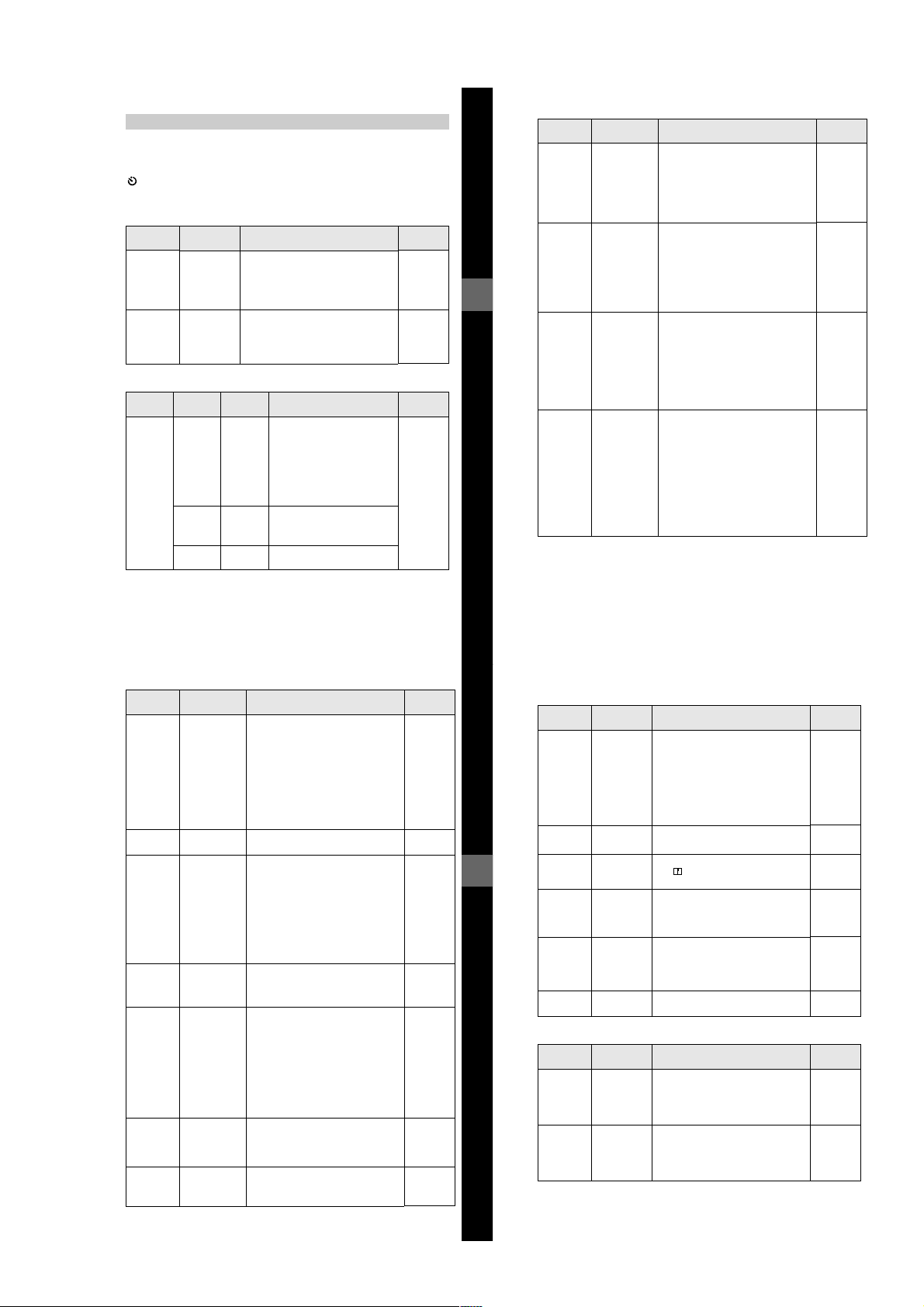
MVC-FD100/FD100H/FD200/FD200H
Menu settings
Menu items that can be modified differ depending on the positions of the PLAY/
STILL/MOVIE selector or the MS/FD selector. The LCD screen shows only the
items you can operate at the moment. Initial settings are indicated with
(self-timer)
Records with the self-timer (page 21).
.
x
EFFECT
Item Setting Description
P. EFFECT SOLARIZE
DATE/
TIME
B&W
SEPIA
NEG.ART
OFF
x
DAY &
TIME
DATE
OFF
x
Sets the image special effects (page 69). STILL
Sets whether to insert the date and time
into the image (page 69).
PLAY/STILL/
MOVIE selector
MOVIE
STILL
FILE
Item-1 Item-2 Setting Description
DISK
TOOL
(When the
MS/FD
selector is
set to FD.)
FORMAT OK Formats a floppy disk (page 81).
CANCEL Cancels formatting of a floppy
DISK
COPY
CANCEL Goes back to the [DISK TOOL]
OK Copies all data stored in a floppy
CANCEL Cancels the disk copy.
Once you format a floppy disk,
all of the data, including
protected images are deleted. Be
sure to check for images before
you format a floppy disk.
disk.
disk to another disk (page 79).
item.
PLAY/STILL/
MOVIE
PLAY
STILL
MOVIE
selector
Before performing advanced operations
Item Setting Description
FORMAT
(When the
MS/FD
selector is
set to MS.)
FILE
NUMBER
CLIP
MOTION
IMAGE
SIZE
(When the
MS/FD
selector is
set to FD.)
OK Formats a “MemoryStick.”Once you
CANCEL Cancels formatting of a “Memory
SERIES Assigns numbers to files in sequence
NORMAL Resets the file number that starts from
x
160×120
(NORMAL)
80×72
(MOBILE)
CANCEL Cancels Clip Motion.
MVC-FD100
1280×960
x
1280(3:2)
1024×768
640×480
MVC-FD200
1600×1200
x
1600 (3:2)
1600 (ECM)
1024×768
640×480
format the “Memory Stick,” all of the
data, including protected images are
deleted. Be sure to check for images
before you format a “Memory Stick.”
Stick.”
even if the floppy disk or the “Memory
Stick” is changed. Note that file
numbers are not in sequence between a
floppy disk and a “Memory Stick.”
001 or 0001 each time the floppy disk or
the “Memory Stick” is changed.
Sets the image size and number of
frames for creating GIF format
animation (page 59).
Up to 10 framescanbe recorded.
Up to 2 frames can be recorded.
Selects the image size when recording
still images.
PLAY/STILL/
MOVIE
selector
PLAY
STILL
MOVIE
STILL
MOVIE
STILL
STILL
Item Setting Description
IMAGE
SIZE
(When the
MS/FD
selector is
set to MS.)
IMAGE
SIZE
REC MODE TIFF Records a TIFF (uncompressed) file in
REC TIME
SET
SLIDE
SHOW
(Only in
PLAY
(single)
mode)
PRINT
MARK
PROTECT ON Protects images against accidental
MVC-FD100
1280 (FINE)
x
1280(3:2) F
1024 (FINE)
640 (FINE)
MVC-FD200
1600 (FINE)
x
1600 (3:2)F
1024 (FINE)
640 (FINE)
320×240
160×112
x
TEXT Records a GIF file in black-and-white.
E-MAIL Records a small-size (320×240) JPEG
NORMAL Records an image using the normal
x
15 sec Selects the recording time for moving
10 sec
5sec
x
INTERVAL Sets the slide show interval.
REPEAT A slide show can be repeated. (When
START Starts the slide show.
CANCEL Cancels the slide show settings or
ON Marks the still images to be printed
OFF Unmarks the print mark of the still
x
OFF Releases protection of images.
x
Selects the image size when recording
still images.
Selects the MPEG image size when
recording moving images.
addition to the JPEG file when the MS/
FD selector is set to MS.
file in addition to the selected image
size.
recording mode.
images.
3 sec/5 sec/10 sec/30 sec/1 min
x
using the floppydisk, a slide show is up
to approx. 20 m inutes.)
ON/OFF
x
execution.
(page 80).
images.
erasure (page 74).
PLAY/STILL/
MOVIE
STILL
MOVIE
STILL
MOVIE
PLAY
PLAY
PLAY
51
selector
53
Before performing advanced operations
52
CAMERA
Item Setting Description
ISO 400
DIGITAL
ZOOM
SHARPNESS
WHITE
BALANCE
FLASH
LEVEL
EXPOSURE +2.0EV to
200
100
AUTO
x
ON Uses a digital zoom. STILL
x
OFF Does not use a digital zoom.
+2 to –2 Adjusts the sharpness of the image.
IN DOOR
OUT DOOR
HOLD
AUTO
x
HIGH Makes the flash level higher than
NORMAL Normal setting.
x
LOW Makes the flash level lower than normal.
–2.0EV
Selects the ISO film speed. When
recording under dark conditions or
recording a fast-moving subject, use a
high-number setting. To record highquality images, use a low-number
setting. (Youcan select this item only
when the PROGRAM AE function is
canceled or spot light-metering mode is
set.)
The indicator appears (except when
the setting is 0).
Sets the white balance (page 68). STILL
normal.
Adjusts the exposure before recording. STILL
TOOL
Item Setting Description
COPY
(When the
MS/FD
selector is
set to FD.)
COPY
(When the
MS/FD
selector is
set to MS.)
FD
FD Copies the image to a floppy disk. PLAY
t
FD
MS Copies the image to a “Memory Stick.”
t
CANCEL Cancels copying of the image (page 78).
MS
MS Copies the image to a “Memory Stick.” PLAY
t
MS
FD Copies the image to a floppy disk.
t
CANCEL Cancels copying of the image (page 78).
54
PLAY/STILL/
MOVIE
STILL
STILL
MOVIE
STILL
MOVIE
PLAY/STILL/
MOVIE
selector
selector
1-13
MVC-FD100/FD100H/FD200/FD200H
Item Setting Description
RESIZE
(When the
MS/FD
selector is
set to FD.)
RESIZE
(When the
MS/FD
selector is
set to MS.)
MVC-FD100
1280×960
1024×768
640×480
CANCEL
MVC-FD200
1600×1200
1024×768
640×480
CANCEL
MVC-FD100
1280 (FINE)
1024 (FINE)
640 (FINE)
CANCEL
MVC-FD200
1600 (FINE)
1024 (FINE)
640 (FINE)
CANCEL
Changes the recorded image size in
PLAY(single) mode (page 76).
Changes the recorded image size in
PLAY(single) mode (page 76).
SETUP
Item Setting Description
DEMO
VIDEO
OUT
LANGUAGE
CLOCK
SET
STBY/ON
x
OFF
NTSC Sets the video output signal to NTSC
PAL Sets the video output signal to PAL
/
ENGLISH Displays the menu items in English. PLAY
x
— Setsthedateandtime(page14). PLAY
Displayed only when you use the AC
power adaptor in STILL or MOVIE
mode. When [ON] is selected, a
demonstration will start if you do not
operate your camera for about 10
minutes. Tostopthedemonstration,turn
off your camera.
mode (e.g., the U.S.A., Japan).
mode (e.g., Europe).
/JPN Displays the menu items in Japanese.
PLAY/STILL/
MOVIE
PLAY
PLAY
PLAY/STILL/
MOVIE
STILL
MOVIE
PLAY
STILL
MOVIE
STILL
MOVIE
STILL
MOVIE
selector
selector
Before performing advanced operations
Item Setting Description
BEEP SHUTTER Turns on the shutter sound only. (The
ON Turns on the beep/shutter sound (when
x
LCD
BRIGHT
OFF Turns off the beep/shutter sound.
shutter sound is heard when you press
the shutter button.)
you press the control button/shutter
button).
Adjusts the LCD screen brightness
using −/+ on the LCD screen.
INDEX (Only in PLAY (single) mode)
Displays six images at a time (PLAY (INDEX) mode).
DELETE (Only in PLAY ( single) mode)
Setting Description
OK Deletes the displayed image. PLAY
CANCEL Cancels deleting of the image.
PLAY/STILL/MOVIE
(Return) (Only in PLAY (INDEX) mode)
Returns to PLAY (single) mode.
PLAY/STILL/
MOVIE
PLAY
STILL
MOVIE
PLAY
STILL
MOVIE
selector
selector
B
Various recording
Setting the image size
(IMAGE SIZE)
1
Set the PLAY/STILL/MOVIE
1
selector to STILL or MOVIE.
Select [FILE] and then
2
[IMAGE SIZE] from the menu.
Select the desired image size.
3
Still image sizes:
• MVC-FD100
When the MS/FD selector is
set to FD
1280×960: 1.2 mega pixels
1280 (3:2)*
1024×768: 0.8 mega pixels
640×480: 0.35 mega pixels
When the MS/FD selector is
set to MS
1280 (FINE): 1.2 mega pixels
1280 (3:2)*F
1024 (FINE): 0.8 mega pixels
640 (FINE): 0.35 mega pixels
• MVC-FD200
When the MS/FD selector is
set to FD
1600×1200: 2.0 mega pixels
1600 (3:2)*
1600 (ECM)
1024×768: 0.8 mega pixels
640×480: 0.35 mega pixels
2, 3
When the MS/FD selector is
set to MS
1600 (FINE): 2.0 mega pixels
1600 (3:2)*
1024 (FINE): 0.8 mega pixels
640 (FINE): 0.35 mega pixels
(FINE): The images recorded on
a “Memory Stick” have a higher
picture quality. The size of a file
that can be recorded on a
“Memory Stick” is also larger
than that of a floppy disk.
(ECM): The picture quality is
lower, but more images can be
recorded. If picture quality is
more important than the number
of images to be recorded, select
[1600×1200].
*Your camera will record an
image using a 3:2 ratio so that it
matches the horizontal and
vertical ratio 3:2 of print paper.
Therefore, there will be no
margin when the image is printed
in the print paper. Please note
that the top and bottom of the
recording range displayed on the
LCD screen (horizontal and
vertical ratio 4:3) is cut off when
the image is recorded in your
camera.
Moving image sizes:
320×240, 160×112
55
57
BB
B Various recording
B
56
The number of images or the time that you can record on a floppy disk or a
“Memory Stick” (8 MB)
MVC-FD100
Image size Usage
1280×960 Printing in post card size Approx. 6 Approx. 12
1280 (3:2) Printing in 3:2 ratio Approx. 6 Approx. 12
1024×768 Home page, etc. Approx. 10 Approx. 20
640×480 Attaching to e-mail Approx.30 Approx. 48
2)
320×240*
160×112*2)Attaching to e-mail Approx. 60 sec.
MVC-FD200
Viewingon computer Approx. 15 sec.
Image size Usage
1600×1200 Printing in size A4 Approx. 4 Approx. 8
1600 (3:2) Printing in 3:2 ratio Approx. 4 Approx. 8
1600
(ECM)
1024×768 Home page, etc. Approx. 10 Approx. 20
640×480 Attaching to e-mail Approx.30 Approx. 48
320×240*
160×112*2)Attaching to e-mail Approx. 60 sec.
*1)When REC MODE is set to NORMAL.
*2)Image size of a moving image.
*3)The maximum recording time in continuous recording.
Recording time and number of images to be recorded
The recording time and the number of images to be recorded may differ from the
above values depending on the recording conditions.
Notes
• If you try to record 55 images or more on a floppydisk,even if the remaining disk capacity is
sufficient,“DISK FULL” appears on the LCD screen and you cannotrecordanymore images.
• If you try to record 3001 imagesor moreona“MemoryStick,”even if the remaining memory
capacity of the “Memory Stick” is sufficient, “NO MEMORY SPACE” appears on the LCD
screen and you cannot record anymoreimages.
• When the TEXT mode is selected, the numberofimagesthat can be recorded will be the same
as that of [1600×1200] even if you select [1600 (ECM)] for imagesize.
Recording a large
number of images
2)
Viewingon computer Approx. 15 sec.
Number of images to be recorded or time
Floppy disk
“Memory Stick”
Approx. 80 sec.
(Approx. 15 sec.)*
Approx. 320 sec.
(Approx. 60 sec.)*
Number of images to be recorded or time
Floppy disk
Approx. 8 –
“Memory Stick”
Approx. 80 sec.
Approx. 320 sec.
(15 sec.)*
(60 sec.)*
*
*
3)
3)
58
1)
3)
3)
1)
1-14
MVC-FD100/FD100H/FD200/FD200H
Tips
The size of the image is indicated by the
pixel unit. The higher the number of
pixels, the more informationisincluded.
So, an image that is saved using a large
number of pixels is suitable foralargeformat print and onethatissaved using a
smaller number of pixelsis suitablefor
attachingtoanE-mail.Normally,an
image is recorded in the ratiooffour to
three to fitthemonitorratio. This camera
can also record the image intheratioof
three to two to accommodate the most
common printing paper size. Thisisthe
same ratio as the one used inphotodeveloping shops.
1280×960
1280 (3:2)
Creating Clip Motion
Files
Clip Motion is an animation function
that plays back still images in
succession. Clip Motion images are
played back on this camera at
approximately 0.5 s intervals. The
images are stored inGIFformat,which
is convenient for creating home pages
or attaching images to an e-mail.
4, 5
1
Set the PLAY/STILL/MOVIE
1
selector to STILL.
Select [FILE] and then [CLIP
2
MOTION] from the menu.
Select the desired mode.
3
160×120 (NORMAL)
Clip Motion of up to 10 frames can
be recorded.
This is suitable for use on home
pages, etc.
80×72 (MOBILE)
ClipMotionofupto2framescan
be recorded.
This is suitable for use with
portable data terminals.
CANCEL
This cancels the creation of Clip
Motion.
2, 3
BB
B Various recording
B
Record the imagefor the first
4
frame.
Record the image for the next
5
frame.
Image recording can be repeated
up to the maximum number of
recordable frames.
The frame images are
automatically recorded on the
floppy disk or the “Memory Stick”
when you select [FINISH] or after
recording the maximum number of
frames.
6
160
2/10
To stop Clip Motion creation
Select [RETURN] after step 3.
Note that if you record evenoneframe,
you cannot stop Clip Motion creation.
The number of Clip Motion frames
that you can record on a floppy
disk or a “Memory Stick” (8 MB)
Image size Number of images
Floppy disk
160×120
(NORMAL)
80×72
(MOBILE)
∗ When recording 10 frames per Clip
Motion file
∗∗Whenrecording 2 frames per Clip
Motion file
“Memory Stick”
Approx.7*Approx.
Approx.
54**
40*
Approx.
400**
Notes
• Reading and writingdatatakesmoretime
than normal image recording.
• Due to the limitations of the GIF format,
the number of colors for ClipMotion
images is reduced to 256 colors or less.
Therefore, the picture quality may
deteriorate for some images.
• The file size is reduced in MOBILE mode,
so the picture quality deteriorates.
• GIF files not created on this camera may
not be displayed correctly.
Recording still
images for e-mail
(E-MAIL)
The E-MAIL mode records a smallsize (320×240) image at the same time
as a still image. Small-size images are
convenient for e-mail transmission,
etc. Images in E-MAIL mode are
recorded in the JPEG format.
3
1
Set the PLAY/STILL/MOVIE
1
selector to STILL.
Select [FILE], [REC MODE],
2
andthen[E-MAIL]fromthe
menu.
Record the image.
3
The number ofimages that you
can record on a floppy disk or a
“Memory Stick” (8 MB) in E-MAIL
mode
MVC-FD100
Image size Number of images
1280×960 Approx. 5 Approx.
1280 (3:2) Approx. 5 Approx.
1024×768 Approx. 8 Approx.
Floppy disk
640×480 Approx.22Approx.
2
“Memory Stick”
12
12
20
43
MVC-FD200
Image size Number of images
1600×1200 Approx. 3 Approx. 8
Floppy disk
1600 (3:2) Approx. 3 Approx. 8
1600
(ECM)
1024×768 Approx. 8 Approx.
640×480 Approx.22Approx.
To return to normal
recording mode
Select [NORMAL] in step 2.
“Memory Stick”
Approx. 7 –
20
43
59
BB
B Various recording
B
60
Recording text
documents (TEXT)
Textis recorded in GIF format to
provide a clear image.
3
1
Set the PLAY/STILL/MOVIE
1
selector to STILL.
Select [FILE], [REC MODE],
2
andthen[TEXT]fromthe
menu.
Record the image.
3
The number of images that you
can record on a floppy disk or a
“Memory Stick” (8 MB) in TEXT
mode
MVC-FD100
Image size Number of images
1280×960 Minimum7Minimum
1280 (3:2) Minimum8Minimum
1024×768 Minimum11Minimum
Floppy disk
640×480 Minimum28Minimum
2
“Memory Stick”
36
40
54
121
MVC-FD200
Image size Number of images
1600×1200 Minimum4Minimum
1600 (3:2) Minimum5Minimum
1600
(ECM)
1024×768 Minimum11Minimum
640×480 Minimum28Minimum
∗ The maximum number of recordable
images depends on the document
condition, such as the amount of text
portions.
To return to normal
recording mode
Select [NORMAL] in step 2.
Notes
• Ifthesubject is not evenlyilluminated, you
may be unable to record a clear image.
• Writing and reading data take moretime
than normal recording.
• When TEXT mode is selected, you cannot
*
use the PROGRAMAEfunction.
Floppy disk
“Memory Stick”
Minimum4–
*
24
26
54
121
61
62
1-15
MVC-FD100/FD100H/FD200/FD200H
Recording still
images as
uncompressed files
(TIFF)
This mode simultaneously records still
images in both TIFF format
(uncompressed) and JPEG format
(compressed) when using a “Memory
Stick.”
Since this mode records images
without compressing data, the quality
of picture will hardly deteriorate. Use
this mode when you want to print
images with photograph picture
quality.
4
1
Set the PLAY/STILL/MOVIE
1
selector to STILL.
Set the MS/FD selector to MS.
2
Select [FILE], [REC MODE],
3
and then [TIFF] from the
menu.
Record the image.
4
The number ofimages that you
can record on a “Memory Stick”
(8 MB) in TIFF mode
MVC-FD100
Image size Number of images
1280×960 1
1280 (3:2) 2
2
3
MVC-FD200
Image size Number of images
1600×1200 1
1600 (3:2) 1
To return to normal
recording mode
Select [NORMAL] in step 3.
Notes
• JPEGimagesarerecorded using the image
size selected in the [IMAGESIZE]menu
(page 57). Images are automatically
recorded using the image size[1280×960]
unless [1280 (3:2)] is selected forMVCFD100.
Images are automatically recordedusing
the image size [1600×1200] unless[1600
(3:2)] is selected for MVC-FD200.
• Writingdatatakesmoretimethanin
normal recording.
63
BB
B Various recording
B
Recording images in
macro
Use this modewhenyourecordasmall
subject such as flower or insect from
close up.
1
2
Set the PLAY/STILL/MOVIE
1
selector to STILL or MOVIE.
Press FOCUS repeatedly
2
until the (macro)indicator
appears on the LCD screen.
With the zoom lever set to the W
side, you can shoot a subject that is
about 3 cm ( 1 3/16 inch) away
from the lens surface in macro
mode.
To return to normal
recording mode
Press FOCUS repeatedly until both the
indicators disappear.
9
and
Notes
• You cannot record images in macrowith
the following PROGRAM AE modes:
—Landscape mode
—Panfocus mode
• You cannot record images in macro if the
indicator appears.
64
Setting the distance
to the subject
The focus is automatically adjusted.
This function is useful when you
record a subject by presetting the
recording distance in accordance with
the distance to the subject or the auto
focus does not work well.
1
2
Set the PLAY/STILL/MOVIE
1
selector to STILL or MOVIE.
Press FOCUS repeatedly
2
until a sharp focus is
achieved.
(manual focus) indicator
The
9
appears on the LCD screen. You
can select from six focus settings:
(macro), 0.5 m, 1.0 m, 3.0 m,
7.0 m, and ∞ (infinity).
To reactivate auto focusing
Press FOCUS repeatedly until both the
9
indicators disappear.
and
Notes
• Focal pointinformationmaynot
completely show the correct distance. Use
the information as a guide.
• Focal pointinformationdoes not show the
correct distance when attachingthe
conversion lens (optional).
• If you shoot a subject within 0.8 m
(31 1/2 inches) while the zoom leverisset
to T side, you cannot get a clear focus. In
such cases, the focal point information
flashes. Move the zoomlevertothe W side
until the indicator stops flashing.
• You cannot use this function if you have
selected the Panfocusmodeinthe
PROGRAM AE function.
Using the PROGRAM
AE function
1
2
Set the PLAY/STILL/MOVIE
1
selector to STILL.
Press PROGRAM AE
2
repeatedly to select the
desired PROGRAM AE mode.
Twilight mode
Suppresses the blurring of colors
of a bright subject in a dark place
so that you can record the subject
without losingthedarkatmosphere
of the surroundings.
Twilight plus mode
Increases the effectiveness of the
twilight mode function.
Landscape mode
Focusesonlyona distant subject to
record landscapes, etc.
Panfocus mode
Changes the focus quickly and
simply from a close subject to a
distant subject.
Spot light-metering mode
Select this mode w hen there is
backlight or when there is strong
contrast between the subject and
the background, etc. Position the
point you wanttorecordatthespot
light-metering cross hair.
LCD screen
Spot light-metering
cross hair
To cancel PROGRAM AE
Press PROGRAM AE repeatedly until
the indicator on the LCD screen goes
out.
Notes
• Y oucanfocus only on distant subjects in
Landscape mode.
• In Panfocusmode, the zoompositionisset
to the W side and focus is fixed.
• When you record in Twilight plus mode,
we recommend that you use a tripod to
preventshaking.
• Set the forced flash when you use the
flash in the following modes:
Twilight mode
–
Twilight plus mode
–
Landscape mode
–
• You cannot use the PROGRAM AE
function when themovingor still image of
TEXT mode is recorded.
• The ISO film speed is settoAUTO when a
PROGRAM AE function other than the
spot light-metering mode is set.
BB
B Various recording
B
Tips
Under normal recording conditions,the
camera automatically makes various
adjustments, such as those for thefocus,
iris, exposure, and white balance,asit
shoots. However, you may not be able to
carry out your desired shooting
depending on shooting conditions.The
PROGRAM AE function provides you
with near-optimum adjustments to suit
your shooting situation.
65
66
1-16
MVC-FD100/FD100H/FD200/FD200H
.
Adjusting the
exposure
(EXPOSURE)
1
Set the PLAY/STILL/MOVIE
1
selector to STILL or MOVIE.
Select [CAMERA] and then
2
[EXPOSURE] from the menu.
Select the desired exposure
3
value.
Adjust the exposure value while
checking the brightness of the
background. Youcan select values
ranging from +2.0 E V to −2.0 EV
in steps of 1/3 EV.
Note
If a subject isunderextremelybrightordark
situations, or the flash isused,the exposure
adjustment may not be effective.
2, 3
Tips
Normally, the camera automatically
adjusts the exposure. If the color of the
image is too dark or brightasshown
below,we recommend that you adjustthe
exposure manually. When recording a
backlighted subject or a subjectinthe
snow,settheexposure toward +, and
when recording a subject withextremely
brightilluminationsuch as a spotlight,set
it toward –.
Set the exposure toward +
Set the exposure toward –
BB
B Various recording
B
Adjusting the white
balance (WHITE
BALANCE)
When the white balance mode is set to
AUTO,yourcameraautomaticallysets
white balance in accordance with the
recording conditions and adjusts the
balance of all colors in an image. If
you want to fix the recording
conditions or record an image in
specific lighting conditions, you can
set the desired white balance mode.
1
Set the PLAY/STILL/MOVIE
1
selector to STILL or MOVIE.
Select [CAMERA] and then
2
[WHITE BALANCE] from the
menu.
Select the desired white
3
balance setting.
IN DOOR (n)
• Places where the lighting
condition changes quickly
• Under bright lighting such as
photography studios
• Under sodium or mercury lamps
OUT DOOR ( )
Recording a sunrise/sunset, night
scene, neon signs, or fireworks
HOLD (HOLD)
Retains the adjusted white balance
value
AUTO(No indicator)
Adjusts the white balance
automatically
2, 3
To reactivate auto adjustment
Select [AUTO] in step 3.
Tips
The image is affected by the lighting
conditions. The image looks blueunder
sunlight in the summer, and looks red
under mercury lamps. Human eyes can
resolve these problems.However,the
camera cannot resolve the problem
without making adjustments. Normally,
the camera adjusts automatically, but if
the image appears in strange colors, we
recommend that you change the white
balance mode.
Recording the date
and time on the still
image (DATE/TIME)
4
1
Set the PLAY/STILL/MOVIE
1
selector to STILL.
Select [EFFECT] and then
2
[DATE/TIME] from the menu.
Select the date and time.
3
DAY & TIME
Superimposes the date, hour, and
minute.
DATE
Superimposes the year,month,and
day.
OFF
Does not superimposes the date
and time.
Record the image.
4
The date and time do not appear on
the LCD screen during shooting.
These appear during playback
only.
Notes
• When [DATE] is selected in step 3,the
date is imposed in the order set by the
CLOCK SET item (page 14).
• The date and time are not imposed onto
Clip Motion images.
2, 3
2002 7 4
Enjoying picture
effects (PICTURE
EFFECT)
1
Set the PLAY/STILL/MOVIE
1
selector to STILL or MOVIE.
Select [EFFECT] and then
2
[P. EFFECT] from the menu.
Select the desired mode.
3
SOLARIZE
The light contrast is clearer andthe
picture looks like an illustration.
B&W
The picture is monochrome (black
and white).
SEPIA
The picture is sepia-toned like an
old photograph.
NEG.ART
The color and brightness of the
picture are reversed as in a
negative.
OFF
Does not use the picture effect
function.
To cancel picture effect
Select [OFF] in step 3.
2, 3
67
69
BB
B Various recording
B
68
B
Various playback
Playing back six
images at once
(INDEX)
1
Set the PLAY/STILL/MOVIE
1
selector to PLAY.
Select [INDEX] on the LCD
2
screen.
Six images are displayed at once
(index screen).
Only the first frameofClipMotion
filesisdisplayed.
2002 7 4 12:30PMMVC-001F
DELETE
FILE SETUPTOOL
SELECT SINGLE DISPLAY
This shows the position of the
currently displayed images relative
to all the recorded images.
The following marks are displayed
on each image according to the
image type and settings.
: Moving image file
:E-mailfile
:Printmark
: Protect mark
-
TEXT: TEXT file
TIFF: TIFF file
CLIP: Clip Motion file
(No mark): Normal recording (no
settings)
70
To display the next
(previous) index screen
Selectv/Vat the lower-left on the
LCD screen.
Displays the previous index
screen.
Displays the next index screen
To return to normal playback
2
(single image)
• Select the desired image with the
control button.
• Select (Return).
Note
When viewing an image recorded in Clip
MotionorTEXTmodeontheINDEX
screen, theimagemay appear different from
the actual image.
1-17
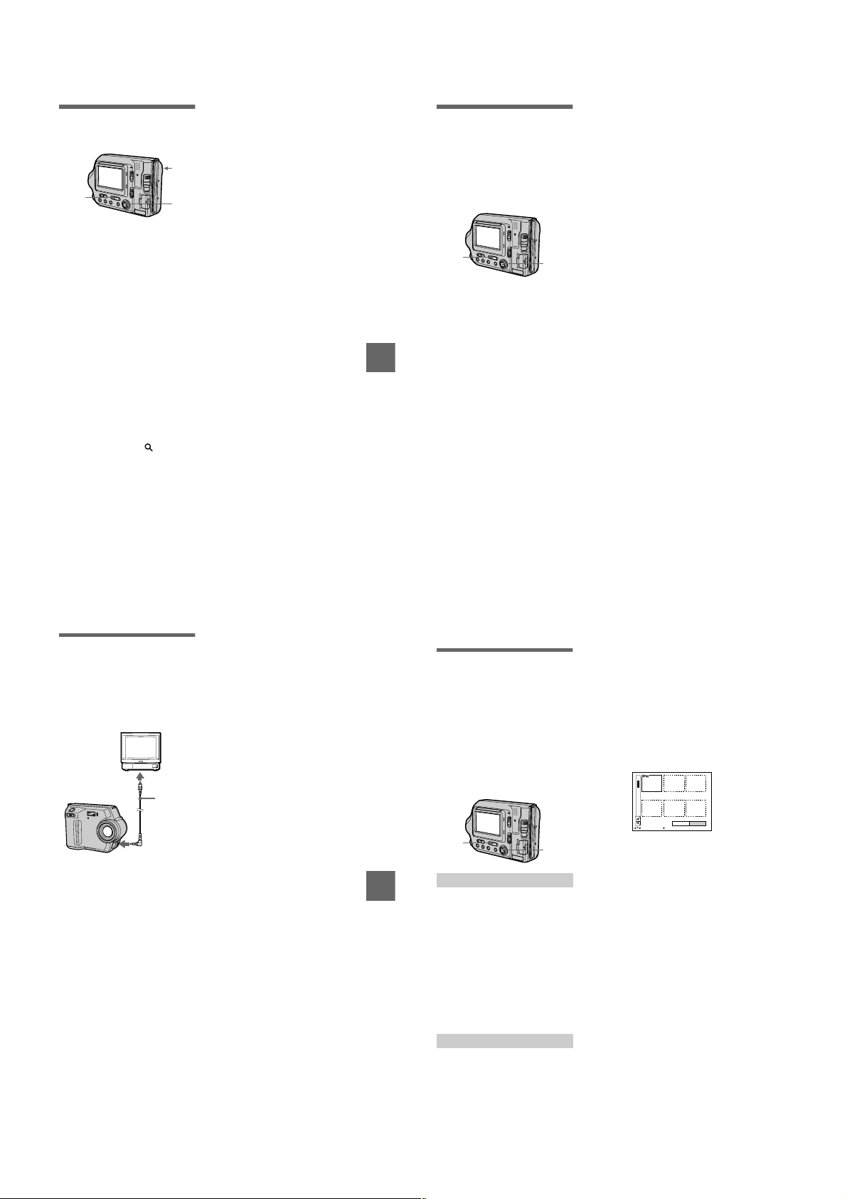
MVC-FD100/FD100H/FD200/FD200H
Enlarging a part of the
still image (Zoom and
trimming)
3
1
Set the PLAY/STILL/MOVIE
1
selector to PLAY.
Displaytheimagetobe
2
enlarged.
Zoom in/out the image with
3
the zoom lever.
The zoom scaling indicator
appears on the LCD screen.
Press the control button
4
repeatedly to select the
desired portion of theimage.
: The image moves downward
v
: The image moves upward
V
: The image moves rightward
b
: The image moves leftward
B
To return to the normal size
Zoom out with the zoom lever until the
zoom scaling indicator ( ×1.1)
disappears from the screen, or simply
press the center
To record an enlarged image
(trimming)
1
Enlarge the image.
Press the shutter button. The image
2
is recorded at 640×480 size and the
image on the LCD screen returns to
the normal size after recording.
.
z
4
Notes
• You cannot trim moving images, still
images recorded in Clip Motion, TEXT
mode, or uncompressed images.
• Zoomscalingisupto5× regardless of the
original image size.
• The quality of enlarged images may be
deteriorated.
• The original data is left evenifyouenlarge
the image.
• The enlargedimageisrecordedasthe
newest file.
Playing back the still
images in order
(SLIDE SHOW)
This function plays back the recorded
still images one after another.
This function is useful forcheckingthe
recorded images or for presentations,
etc.
1
Set the PLAY/STILL/MOVIE
1
selector to PLAY.
Select [FILE] and then [SLIDE
2
SHOW] from the menu.
Set the following items.
INTERVAL
B Various playback
Youcanselect from 1 min (one
minute), 30 sec (30 seconds),
10 sec (10 seconds), 5 sec
(5 seconds), or 3 sec (3 seconds).
REPEAT
ON: Plays back images
continuously in a loop until
[RETURN] is selected (the slide
show stops automatically after
approximately 20 minutes* when
the image is played back from a
floppy disk).
OFF: After all images have been
played back, the slide show ends.
∗ The slide show does not end until all
the images are played back, even if it
takes more than 20 minutes.
Select [START].
3
The slide show begins.
2, 3
To cancel the slide show
Select [CANCEL] in step 2 or 3.
To skip to the next/previous
image during the slide show
Select\b/
LCD screen.
Note
The interval settingtimemayvary
depending on the image size.
at the lower-left on the
B\
Viewing images on a
TV screen
You can play back the recorded images
by connecting your camera to the TV.
Before connecting your camera, be
sure to turn off the TV,connect the
VIDEO connecting cable, and turn on
the TV.
Set the TV/VIDEO
switch to
“VIDEO”.
To VIDEO
INPUT jack
VIDEO
connecting
cable
(supplied)
To VIDEO OUT jack
Connect the VIDEO
1
connecting cable to the
VIDEO OUT jack of your
camera and to the VIDEO
INPUT jack of the TV.
Turnon the TV and start
2
playback on your camera.
The playback imageappearsonthe
TV screen.
Note
• You cannot use a TV that has an antenna
(aerial) connector only.
• When viewing a still image on the TV ,the
black band may appear aroundtheimage.
71
72
B
Editing
Preventing accidental
erasure (PROTECT)
This function is used to prevent any
valuable images that you have
recorded from being erased
accidentally.
(protect) indicator appears on
-
The
protected images.
Note:
If you format a floppy disk ora“Memory
Stick”, allimagesare erased evenwhenthey
are protected.
1
In single mode
B Various playback
Set the PLAY/STILL/MOVIE
1
selector to PLAY, then
display the image to be
protected.
Select [FILE], [PROTECT],
2
andthen[ON]fromthemenu.
The displayed image is protected
indicator appears.
-
and the
To release protection
Select [OFF] in step 2.
In INDEX mode
Set the PLAY/STILL/MOVIE
1
selector to PLAY, then
display the INDEX screen.
2, 3
Select [FILE], [PROTECT],
2
andthen[ALL]or[SELECT]
from the menu.
When you select [ALL]
3
Select [ON].
All the images in thefloppydiskor
the “Memory Stick” are protected.
When you select [SELECT]
Select all the images to be
protected with the control button,
then select [ENTER]. The selected
images are protected.
0001-0006/0040
ENTERPROTECT CANCEL
SELECT OK
To release protection
If you selected [A LL] in step 2, select
[OFF]. If you selected [SELECT] in
step 2, select the images to be
unprotected with the control button,
then select [ENTER].
73
74
1-18
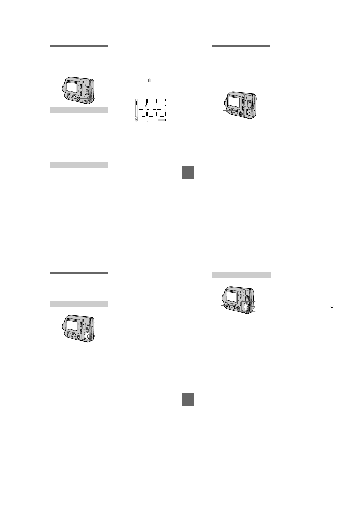
MVC-FD100/FD100H/FD200/FD200H
Deleting images
(DELETE)
You can delete the images that are no
longer required.
Protected images cannot be deleted.
1
In single mode
Set the PLAY/STILL/MOVIE
1
selector to PLAY, then
display the image to be
deleted.
Select [DELETE] and then
2
[OK] from the menu.
The image is deleted.
In INDEX mode
Set the PLAY/STILL/MOVIE
1
selector to PLAY, then
display the INDEX screen.
Select [DELETE] and then
2
[ALL] or [SELECT] from the
menu.
2, 3
When you select [ALL]
3
Select [ENTER].
All the unprotected images are
deleted.
When you select [SELECT]
Select all the images to be deleted
with the control button, then select
[ENTER]. The (delete)
indicator appears on the selected
images and these images are
deleted.
0001-0006/0040
ENTERDELETE CANCEL
SELECT OK
To cancel deleting
Select [CANCEL] in step 2 or 3.
Note
If there are files on the “Memory Stick”
with names having the same last 4 digits as
the file name of the image to be deleted,
these files are also deleted at the same time.
75
BB
B Editing
B
Changing the
recorded still image
size (RESIZE)
Use this function when you need a
small-size image to attach it to an
E-mail. The original image is retained
even after resizing. The resized image
is recorded as the newest file.
1
Set the PLAY/STILL/MOVIE
1
selector to PLAY, then
display the image of which
youwanttochangethesize.
Select [TOOL] and then
2
[RESIZE] from the menu.
Select the desired size.
3
• MVC-FD100:
When the MS/FD selector is
set to FD
1280×960, 1024×768, 640×480
When the MS/FD selector is
set to MS
1280 (FINE), 1024 (FINE),
640 (FINE)
• MVC-FD200:
When the MS/FD selector is
set to FD
1600×1200, 1024×768, 640×480
When the MS/FD selector is
set to MS
1600 (FINE), 1024 (FINE),
640 (FINE)
The resized image is recorded,
then the display returns to the
image display before resizing.
2, 3
76
To cancel changing the size
Select [CANCEL] in step 3.
Notes
• You cannot change the size ofimages
recorded in TEXT mode, moving images,
uncompressed images, or Clip Motion
images.
• When you change from a small sizetoa
large size, the picture quality deteriorates.
• If you resize the recorded still image, the
space remaining on a floppy diskora
“Memory Stick” will decrease.
• You may not be able to resizearecorded
still image if there is insufficientspace
remaining on a floppy disk or a “Memory
Stick.”
• You cannot resize the recordedstillimage
to an image size of 3:2.
• If youresizea 3:2 size recorded stillimage
to another size, a black bandwillbe
displayed above and below the resized
image.
• You cannot resize the recordedstillimage
in the index screen.
Copying images
(COPY)
Copies images to another floppy disk
or “Memory Stick.”
In single mode
2
1
5
3, 4
Select the media using the
1
MS/FD selector.
Set the PLAY/STILL/MOVIE
2
selector to PLAY, then
display the image to be
copied.
Select [TOOL], and then
3
[COPY] from the menu.
Select the media that the
4
image will be copied onto.
• When the MS/FD selector is
set to FD.
FD
FD
t
Copies to the floppy disk
FD
MS
t
Copies to the “Memory Stick”
• When the MS/FD selector is
set to MS.
MS
MS
t
Copies to the “Memory Stick”
MS
FD
t
Copies to the floppy disk
When you select [FD
FD], the camera
[MS
t
automatically starts copying if the
floppy disk and “Memory Stick”
are inserted.
Insert orchange the floppy
5
disk or the “Memory Stick”
following the messages on
the LCD screen.
“RECORDING” appears. When
copying is completed,
“COMPLETE” appears.
Toend copying, select [EXIT].
To continue copying the
image to other floppy disks
or “Memory Stick”s
After“COMPLETE”appearsinstep5,
select [CONTINUE] and repeat step 5
above.
t
MS] or
BB
B Editing
B
In INDEX mode
2
Select the media using the
1
MS/FD selector.
Set the PLAY/STILL/MOVIE
2
selector to PLAY, then
display the INDEX screen.
Select [TOOL], and then
3
[COPY] from the menu.
Select the media that the
4
image will be copied onto.
• When the MS/FD selector is
set to FD.
FD
FD
t
Copies to the floppy disk
MS
FD t
Copies to the “Memory Stick”
• When the MS/FD selector is
set to MS.
MS
MS
t
Copies to the “Memory Stick”
MS
FD
t
Copies to the floppy disk
1
6
3, 4, 5
When you select [ALL]*
5
Select [OK].
∗ [ALL] can be selected only when
selecting [FDt FD] or [FD
MS].
When you select [SELECT]**
Select all the images to be copied
with the control button. The
mark appears on the selected
images and then select [ENTER].
∗∗Whenselecting[MSt FD], the
necessary number of floppy disks
appears after selecting [ENTER].
Select [OK] again.
Insert or change the floppy
6
disk or the “Memory Stick”
following the messages on
the LCD screen.
“RECORDING” appears. When
copying is completed,
“COMPLETE” appears.
Toend copying, select [EXIT].
To continue copying the
image to other floppy disks
or “Memory Stick”s
After “COMPLETE”appearsinstep 6,
select [CONTINUE] and repeat step 6.
When selecting [MS
amount of total images that will be
copied is too large to copy to one
floppy disk, the images will be copied
using multiple floppy disks.
t
t
FD], if the
To cancel copying partway
Select [CANCEL].
77
78
1-19
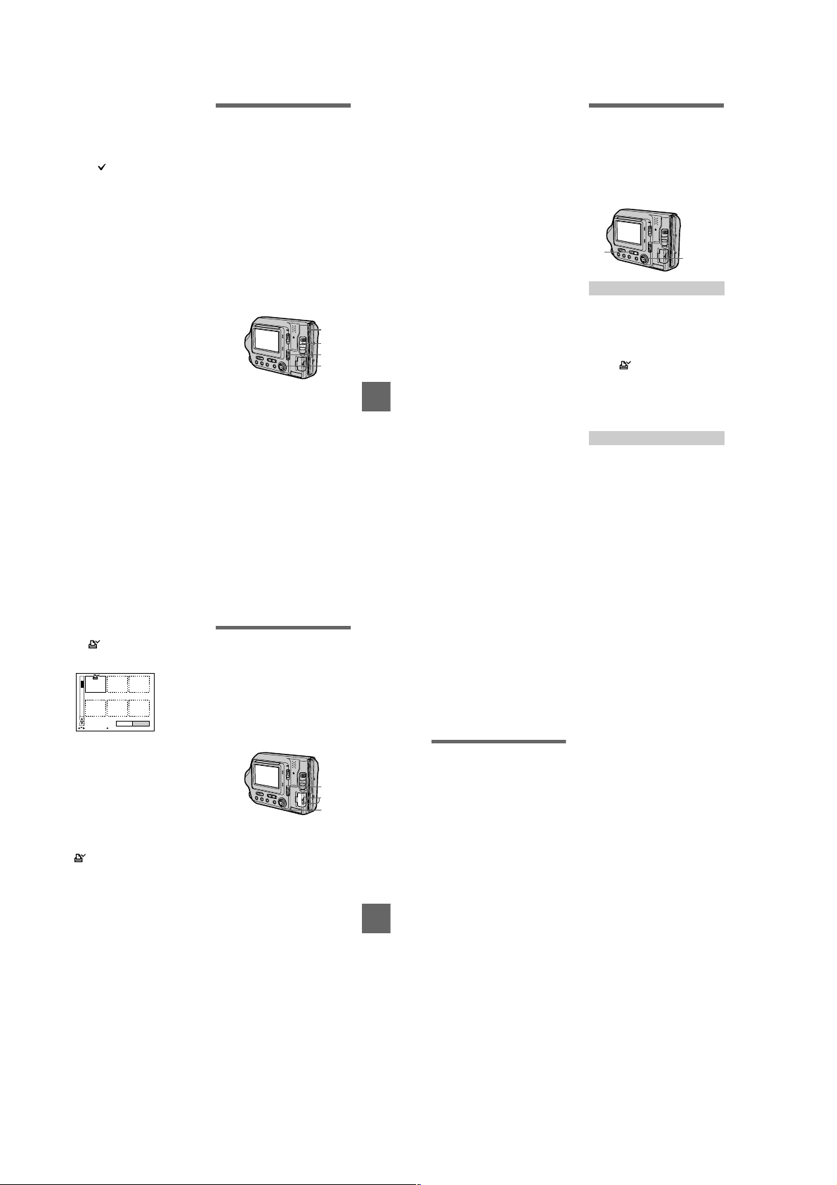
MVC-FD100/FD100H/FD200/FD200H
Notes
• You cannot copy uncompressed images.
• You cannot copy the image that is bigger
than 1.4 MB.
• You cannot copy the images that the total
amount of the images is bigger than
1.4 MB. If “NOT ENOUGH MEMORY”
appears or flashes on the INDEX
screen,cancelsome images to copyandtry
again.
• If you eject and insert the floppydiskor
the “Memory Stick” without selecting
[EXIT] after “COMPLETE” appears, the
image will be copied.
• The number of floppy disks that is needed
for copying is as a guide, whichis
displayed when selecting [MS
FD].
t
Copying all the
information on your
floppy disk (DISK
COPY)
Youcancopy to another disk not only
the images you have recorded with
your camera but also various files you
have created in other software with
your computer.
Notes
• Once you carry out DISK COPY, all
information saved on the recipient floppy
disk is erased to be replacedbynewly
written data including the protected image
data. Check the contents of the recipient
disk before copying the disk.
• Be sure tousethefloppydisk that has been
formattedbythiscameratocarryout
DISK COPY (page 81).
1, 4
3
1
2
Set the MS/FD selector to FD,
1
theninsertthefloppydiskto
be copied.
Select [FILE], [DISK TOOL],
2
[DISK COPY], and then [OK]
from the menu.
“DISK ACCESS” appears.
When “CHANGE FLOPPY
3
DISK” is displayed, eject the
floppy disk.
“INSERT FLOPPY DISK”
appears.
BB
B Editing
B
Insert another floppy disk.
4
“RECORDING” appears. When
copying is completed,
“COMPLETE” appears.
Toend copying, select [EXIT].
To cont inue copying to other
floppy disks
After “COMPLETE” appears instep4,
select [CONTINUE] andrepeatsteps3
and 4 above.
To cancel copying partway
Select [CANCEL].
Note
If you eject and insert the floppy disk
without selecting [EXIT] after
“COMPLETE” appears, DISK COPY will
be carried out onto the floppy disk.
Selecting still images
to print (PRINT MARK)
Youcanmarkaprintmarkonstill
images recorded with your camera.
This mark is convenient when you
have images printed at a shop that
conforms with the DPOF (Digital Print
Order Format) standard.
1
In single mode
Set the PLAY/STILL/MOVIE
1
selector to PLAY and display
the image you want to print.
Select [FILE], [PRINT MARK],
2
andthen[ON]fromthemenu.
The (print) mark is marked on
the displayed image.
To unmark the print mark
Select [OFF] in step 2.
In INDEX mode
Set the PLAY/STILL/MOVIE
1
selector to PLAY, then
display the INDEX screen.
Select [FILE], [PRINT MARK],
2
andthen[SELECT]fromthe
menu.
Select the images to be
3
markedwiththecontrol
button.
2, 3, 4
Select [ENTER].
4
The marks on the selected
images change from green to
white.
0001-0006/0100
ENTERPRINT MARK CANCEL
SELECT OK
To unmark selected print
marks
Select the images to be unmarked in
step 3 with the control button, then
select [ENTER].
To unmark all the print
marks
Select [FILE], [PRINT MARK],
[ALL], and then [OFF] from the menu.
The marks on all images are
removed.
To print out using the FVP-1
Mavica Printer
Set PRESET SELECT SW to PC on
the printer.
Notes
• You cannot mark moving images, Clip
Motion images or imagesrecordedin
TEXT mode.
• If you mark an image recorded in TIFF
mode with a print mark, only the
uncompressed image is printed, and the
JPEG image recorded at the same time is
not printed.
Format
When you format a floppy disk or a
“Memory Stick,” all data stored on the
floppy diskorthe“MemoryStick”will
be deleted. Check the contents of the
floppy disk or the “Memory Stick”
before formatting.
Note
Even if images are protected,theseimages
will be deleted.
1
2
3
Selectthefloppydiskorthe
1
“Memory Stick” using the
MS/FD selector.
Insert only the floppy disk or
2
the “Memory Stick” you want
to format.
Be sure to insert only the media
you want to format.
Select [FILE] from the menu.
3
• When formatting afloppydisk
Select [DISK TOOL],
[FORMAT], and then [OK] from
the menu.
• When formatting a “Memory
Stick”
Select [FORMAT],and then
[OK] from the menu.
To cancel formatting
Select [CANCEL] in step 3.
79
BB
B Editing
B
80
Notes
• Formatthefloppydiskorthe
“Memory Stick” only using this
camera. You cannot format the
floppy disk or the “Memory Stick”
using a computer via the USB cable.
• When you format, be sure to use a fully
charged battery pack or the AC power
adaptor as the power source.
B
As an external drive
Using the camera as
an external drive of a
computer
Once you connect the camera to a
computer using the USB cable, you
can use the camera as a floppy disk/
“Memory Stick” drive of a computer.
Install the USB driver to the computer
beforehand (page 29).
For Windows 98, Windows
98SE, Windows 2000,
Windows Me and Windows
XP Users
Select the drive type using
1
the MS/FD selector on this
camera.
When used as the floppy disk
drive, set the MS/FD selector to
FD.
When used as the “Memory Stick”
drive, set the MS/FD selector to
MS.
Connect the AC power
2
adaptor and turn on the
camera.
Connect the camera to the
3
computer using the supplied
USB cable.
Open “My Computer” on
4
Windowsandchecktheicon
“Removable Disk,” then use
thecameraasanexternal
drive.
Note
• When using Windows2000,Windo wsMe,
or WindowsXP,seealsopage 31.
• The drive symbol ((D:), etc.) may differ
depending on your computer.
• If you are using Mac OS X(v10.0/v10.1),
you can use only a “Memory Stick” with a
computer running Mac OS X(v10.0/
v10.1). Even if you insert a floppy disk,
Mac OS X(v10.0/v10.1) cannot recognize
it. Tousedatasavedonafloppydisk,
copy it to a “Memory Stick” first
(page 77).
81
82
1-20

MVC-FD100/FD100H/FD200/FD200H
Additional information
Precautions
On cleaning
Cleaning the LCD screen
Wipe the screen surface with a
cleaning cloth (optional) or an LCD
cleaning kit (optional) to remove
fingerprints, dust, etc.
Cleaning the camerasurface
Clean the camera surface with a soft
cloth slightly moistened with water,
then wipe the surface dry. Do not use
any type of solvent such as thinner,
alcohol or benzene as this may damage
the finish or the casing.
After using your camera at the
seashore or otherdusty locations
Clean your camera carefully.
Otherwise, the salty air may corrode
the metal fittings or dust may enter the
inside of your camera, causing a
malfunction.
On floppy disks
Toprotect data recorded on floppy
disks, note the following:
• Avoid storing floppy disks near
magnets or magnetic fields such as
those of speakers and televisions.
Otherwise, permanent erasure of disk
data may result.
• Avoid storing floppy disks in areas
subject to direct sunlight or sources
of high temperature, such as a
heating device. Floppy disk warping
or damage may result, rendering the
disk useless.
• Avoid contact with the disk’ssurface
by opening the disk shutter plate. If
the disk’s surface becomes
blemished, data may be rendered
unreadable.
• Avoidgetting liquids on the floppy
disk.
• Be sure to use a floppy disk case to
ensure protection of important data.
• Even when you use a 3.5-inch 2HD
floppy disk, image data may not be
recorded and/or displayed depending
on the using environment. In this
case, use a disk of other brand.
On operating temperature
Yourcamerais designed for use
between the temperatures of 0°Cto
40°C(32°Fto104°F). Recording in
extremely cold or hot places that
exceed this range is not recommended.
On moisture condensation
If the camera is brought directly from a
cold to a warm location, or is placed in
a very damp room, moisture may
condense inside or outside the camera.
Should this occur, the camera will not
operate properly.
Moisture condensation occurs
easily when:
• The camera is brought from a cold
location such as a ski slope into a
warmly heated room.
• The camera is taken from an air-
conditioned room or car interior to
the hot outdoors, etc.
How to prevent moisture
condensation
When bringing the camera from a cold
place to a warm place, seal the camera
in a plastic bag and allow it to adapt to
conditions at the new location over a
period of time (about an hour).
83
If moisture condensation occurs
Immediately eject the floppy disk, then
turn off the camera and wait about an
hour for the m oisture to evaporate.
Note that if you attempt to record with
moisture remaininginsidethelens, you
will be unable torecord clear images.
On AC power adaptor
• Unplug the unit from the wall outlet
(wall socket) when you are not using
the unit for a long time. To
disconnect the power cord (mains
lead), pull it out by the plug. Never
pull the power cord (mains lead)
itself.
• Do not operate the unit with a
damaged cord (mains lead) or if the
unit has been dropped or damaged.
• Do not bend the power cord (mains
lead) forcibly,orplaceaheavy object
Additional information
on it. This will damage the cord
(mains lead) and may cause fire or
electrical shock.
• Preventmetallicobjectsfromcom ing
into contact with the metal parts of
the connecting section. If this
happens, a short may occur and the
unit may be damaged.
• Always keep metal contacts clean.
• Do not disassemble the unit.
• Do not apply mechanical shock or
drop the unit.
• While the unit is in use, particularly
during charging, keep it away from
AM receivers and video equipment.
AM receivers and video equipment
disturb AM reception and video
operation.
• The unit becomes warm during use.
This is not a malfunction.
• Do not place the unit in locations that
are:
— Extremely hot or cold
— Dusty or dirty
— Very humid
— Vibrating
On battery pack
• Use only the specified charger with
the charging function.
• To prevent accident from a short
circuit, do not allow metal objects to
come into contact with the battery
terminals.
• Keep the battery pack away from
fire.
• Never expose the battery pack to
temperatures above 60°C (140°F),
such as in a car parked in the sun or
under direct sunlight.
• Keep the battery pack dry.
• Do not expose the battery pack to any
mechanical shock.
• Do not disassemble nor modify the
battery pack.
• Attach the battery pack to the camera
securely.
• Charging while some capacity
remains does not affect the original
battery capacity.
On the built-in rechargeable
lithium battery
Your camera is supplied with a built-in
rechargeable lithium battery installed
to retain the date/time and various
settings, regardless of the setting of the
POWER switch. The built-in
rechargeable lithium battery is always
charged as long as you are using your
camera. The battery, however, will get
discharged gradually if you do not use
your camera. It will be completely
discharged in about one month if you
do not use your camera at all. Even if
the built-in rechargeable lithium
battery is not charged, it will not affect
the camera operation. To retain the
date andtime,etc.,chargethe battery if
the battery is discharged.
84
Charging the built-in rechargeable
lithium battery:
• Connect your camera to house
current (mains) using the AC power
adaptor supplied with your camera,
and leave your camera with the
power turned off for more than 24
hours.
• Or install the fully charged battery
pack in your camera, and leave your
camera with the power turned off for
more than 24 hours.
If any problem occurs, unplug your
camera and contact your nearest Sony
dealer.
On “Memory Stick”s
“Memory Stick” is a new compact,
portable and versatile IC recording
medium with a data capacity that
exceedsafloppydisk.“Memory Stick”
is specially designed for exchanging
and sharing digital data among
“Memory Stick” compatible products.
Because it is removable, “Memory
Stick” can also be used for external
data storage.
There are two types of “Memory
Stick”s: general “Memory Stick”sand
“MagicGate Memory Stick”sthatare
equipped with the MagicGate*
copyright protection technology.
Y oucan use both typesof “Memory
Stick” with your camera. However,
because your camera does not support
the MagicGate standards, data
recorded with your camera is not
subject to MagicGate copyright
protection.
∗ MagicGate is copyright protection
technology that uses encryption
technology.
Notes
• It is recommended that you make abackup
copy of your important data.
• Do not removethe“MemoryStick”while
reading or writing data.
• Data may be damaged if:
—you remove the “Memory Stick” or turn
offyourcamera whilereadingor writing
data.
—you use the “Memory Stick” in a
location subject to the effectsofstatic
electricity or noise.
• Do not attach any other material than the
supplied label on the labeling position.
• When you carry or store the “Memory
Stick,” putitinitssuppliedcase.
• Do not touch the terminals of a “Memory
Stick” with your hand or a metal object.
• Do not strike, bend or drop the “Memory
Stick.”
• Do not disassembleor modifythe
“Memory Stick.”
• Do not allow the “Memory Stick” to get
wet.
• Do not use or keep “Memory Stick”sin
locations that are:
—Extremely hot such as in a car parked in
the sun or under the scorchingsun.
—Under direct sunlight.
—Veryhumidor subject to corrosive
gases.
“Memory Stick”,,“MagicGate
Memory Stick” and are
trademarks of Sony Corporation.
“MagicGate” and
are trademarks of Sony Corporation.
Using your camera
abroad
Power sources
Youcanuse your camera in any
country or area with the supplied
battery charger within 100 V to 240
VAC,50/60Hz.Use a commercially
available AC plug adaptor [a],if
necessary,depending on the design of
thewalloutlet(wallsocket)[b].
About “InfoLITHIUM”
battery pack
AC-L10A/L10B
Watching the playback picture on
TV
If you want to view the playback
picture on a TV,you need a TV having
a video input jack and a video
connecting cable.
The color system of the TV must be
the same as that of your digital still
camera. Check the following list:
NTSC system
Bahama Islands, Bolivia, Canada,
Central America, Chile, Colombia,
Ecuador, Guyana, Jamaica, Japan,
Additional information
Korea, Mexico, Peru, Surinam,
Taiwan,the Philippines, the U.S.A.,
Venezuela, etc.
PALsystem
Australia, Austria, Belgium, China,
Czech Republic, Denmark, Finland,
Germany,Holland, Hong Kong,
Hungary,Italy, Kuwait, Malaysia, New
Zealand, Norway, Poland, Portugal,
Singapore, Slovak Republic, Spain,
Sweden,Switzerland,Thailand,United
Kingdom, etc.
PAL-Msystem
Brazil
PAL-Nsystem
Argentina, Paraguay, Uruguay
SECAM system
Bulgaria, France, Guiana, Iran, Iraq,
Monaco, Russia, Ukraine, etc.
What is the “InfoLITHIUM” battery
pack?
The “InfoLITHIUM” battery pack is a
lithium-ion battery pack that has
functions for communicating
information related to operating
conditions between your camera and
the AC adaptor/charger (optional).
The “InfoLITHIUM” battery pack
calculates power consumption
according to the operating conditions
of your camera and displays the
remaining battery time in minutes. If
you use the AC adaptor/charger
(optional), it will calculate and display
the operation time and charging
completion time also.
Charging the batterypack
• Be sure to charge the battery pack
before you start using your camera.
• We recommend charging the battery
pack in an ambient temperature of
between 10°Cto30°C(50°Fto86°F)
until the POWER ON/OFF (CHG)
lamp goes out, indicating that the
battery pack is fully charged. If you
charge the battery pack outside of
this temperature range, you may not
be able to efficiently charge the
battery pack.
• After charging is completed, either
disconnect the AC power adaptor
from the DC IN jack on your camera
or remove the battery pack.
85
86
1-21
MVC-FD100/FD100H/FD200/FD200H
Effective use of the battery pack
• Batteryperformance decreases in
low-temperature surroundings. So,
the time that the battery pack can be
used is shorter in cold places. We
recommend the following to use the
battery pack longer:
— Put the battery pack in a pocket
close to your body to warm it up,
and insert it in your camera
immediately before you start
taking shots.
— Use the large capacity battery
pack (NP-F550, optional).
• Frequently using the LCD panel or
frequently operating the zoom wears
out the battery pack faster. We
recommend using the large capacity
battery pack (NP-F550, optional).
• Be certain to turn the POWER switch
to off when not taking shots or
playing back on your camera.
• Procure spare batteries that can last
two or three times longer than the
expected recording time. Also, make
a trial recording before you record
the actual images.
• Do not expose the battery pack to
water. The battery pack is not waterresistant.
Remaining battery time indicator
• If the power goes off although the
battery remaining indicator indicates
that the battery pack has enough
power to operate, charge the battery
pack fully againsothattheindication
on the battery remaining indicator is
correct. Note, however, that the
correct battery indication sometimes
will not be restored if it is used in
high temperatures for a long time or
left in a fullychargedstate, or the
battery pack is frequently used.
Regard the remaining battery time
indication as the approximate
shooting time.
E
mark indicating there islittle
• The
remaining battery time sometimes
flashes depending on the operating
conditions or ambient temperature
and environment even if the
remaining battery time is 5 to 10
minutes.
How to store the battery pack
• If the battery pack is not used for a
long time, do the following
procedure once per year to maintain
proper function.
1. Fully charge the battery.
2. Discharge on your camera.
3. Remove the battery from your
camera and store it in a dry, cool
place.
• Touse the battery pack up on your
camera, leave the POWER switch to
on in PLAY mode until the power
goes off without a floppy disk or a
“Memory Stick” inserted.
Battery life
• The battery life is limited. Battery
capacity decreases little by little as
youuseitmoreandmore,andas
time passes. When the battery
operating time is shortened
considerably,aprobablecause is that
the battery pack has reached the end
of its life. Please buy a new battery
pack.
• The battery life varies according to
how it is stored and operating
conditions and environment for each
battery pack.
Troubleshooting
If you experience trouble with your camera, first check the following items. Should
your camera still not operate properly after you have made these checks, consult your
Sony dealer or local authorized Sony service facility.Ifcode displays (C:
appear on the LCD screen, the self-diagnosis display function is working
(page 95).
Symptom Cause and/or Solution
Your camera does not
work.
Additional information
Your camera cannot
record images.
The picture is out of focus. • Yourcamera is not in macro recording mode when
The resizingfunctiondoes
not work.
• You are not using an “InfoLITHIUM” battery pack.
Use an “InfoLITHIUM” battery pack (page 9).
t
• The floppy disk is not inserted properly.
Eject the disk, and insert it again (page 16).
t
• The battery level is too low.(The indicator
appears.)
Charge the battery pack fully (page 10).
t
• The AC power adaptor is not connected securely.
Connect it securely to the DC IN jack and a wall
t
outlet (wall socket) (pages 10, 13).
• The malfunction occurs inside the camera.
Turn off the power, and turn on after one
t
minute, then check that the camera works
properly.
• The PLAY/STILL/MOVIEselector is set to PLAY.
Set it to STILL or MOVIE (pages 18, 23).
t
• No floppy disk is inserted into your camera.
Insert a floppy disk (page 16).
t
• The tab on the disk is set to the unrecordable
position.
Set it to the recording position (page 16).
t
• No “Memory Stick” is inserted into your camera.
Insert a “Memory Stick” (page 17).
t
• The write-protect switch on the “Memory Stick” is
set to LOCK.
Set it to the recording position.
t
you shoot a subject that is about 3 to 25 cm
(1 3/16 to 9 7/8 inches) away from the lens.
Set the macro recording mode (page 64).
t
Move the zoom lever to the W side.
t
• You cannot resizemovingimages,textimages,Clip
Motion images, and uncompressed images.
ss:ss
)
Symptom Cause and/or Solution
You cannot display a print
mark.
The picture is noisy. • Your camera is placed near a TV or o ther
The picture is too dark. • You are shooting a subject with a light source
The flash does not work. • The flash is set to .
Thedateandtimeare
recorded incorrectly.
Vertical streaks appear
when you are shooting a
very bright subject.
The zoom does not work. • PROGRAM AE is set to the Panfocus mode.
Digital zoom does not
work.
The image is in
monochrome.
The image cannot be
playedbackona
computer.
• You cannot display print marks on moving images,
text images and Clip Motion images.
equipment that uses strong magnets.
Move your camera away from the TV,etc.
t
behind the subject.
Adjust the exposure (page 67).
t
• The brightness of the LCD screen is too low.
Adjust the brightness of the LCD screen
t
(page 20).
Set the flash to (no indication), , or
t
(page 22).
• The camera is in one of the following PROGRAM
AE modes: Twilight, Twilight plus, or Landscape.
Cancel the PROGRAM AE function or set the
t
flash to (pages 22, 65).
• The PLAY/STILL/MOVIE selector is set to
MOVIE.
SetittoSTILL.
t
• The date and time are not set correctly.
Set the correct date and time (page 14).
t
• This is called the smear phenomenon.
This is not a malfunction.
t
Cancel the Panfocus mode (page 65).
t
• You cannot use digital zoom when recording
moving pictures.
• Digital zoom is set to [OFF].
Set digital zoom to [ON] at the menu.
t
• You shot the image in TEXT mode.
Cancel the TEXT mode(page 62).
t
• The picture effect is set to B&W.
Cancel the B&W mode (page 69).
t
Consult the computer or software manufacturer.
t
87
88
Symptom Cause and/or Solution
The moving image breaks
off when you play back an
image on a computer.
Your camera cannotdelete
an image.
The power turns off
suddenly.
The image does not
appear on the TV screen.
Additional information
The slide show function
stops automatically.
Youcannotuse the
PROGRAM AE function.
The macro function does
not work.
• You are playing back the file from the floppy disk
or the “Memory Stick.”
Copy the file to the hard disk of the computer
t
and then play back the file from the hard disk
(page 32).
• The image is protected.
Cancel the protection (page 74).
t
• With the PLAY/STILL/MOVIEselector set to
STILL or MOVIE,if you do not operate the camera
for about three minutes while the power is on, the
camera turns off automatically to prevent wearing
down the battery pack.
Turn on the camera.
t
• The battery pack is discharged.
Replace it with a fully charged battery pack.
t
• The VIDEO OUT setting of your camera is
incorrect.
Change the setting (page 55).
t
• The slide show function stops after about
20 minutes when using a floppy disk.
Tocontinue the slide show, select [START]
t
again (page 72).
• Your camera is set to TEXT mode or the PLAY/
STILL/MOVIE selector is set to MOVIE.
Set the PLAY/STILL/MOVIEselectortoSTILL
t
and change the setting (pages 53, 54).
• PROGRAM AE is set to the Panfocus mode.
Cancel the Panfocus mode (page 65).
t
89
90
1-22
 Loading...